JP2010067020A - Vehicle driving support device - Google Patents
Vehicle driving support device Download PDFInfo
- Publication number
- JP2010067020A JP2010067020A JP2008232922A JP2008232922A JP2010067020A JP 2010067020 A JP2010067020 A JP 2010067020A JP 2008232922 A JP2008232922 A JP 2008232922A JP 2008232922 A JP2008232922 A JP 2008232922A JP 2010067020 A JP2010067020 A JP 2010067020A
- Authority
- JP
- Japan
- Prior art keywords
- head
- driver
- speakers
- vehicle
- sound
- Prior art date
- Legal status (The legal status is an assumption and is not a legal conclusion. Google has not performed a legal analysis and makes no representation as to the accuracy of the status listed.)
- Granted
Links
Images


Abstract
Description
本発明は、車両運転支援装置に関し、より詳しくは、スピーカから出力される音響音による運転支援に関する。 The present invention relates to a vehicle driving support device, and more particularly to driving support using acoustic sounds output from a speaker.
自動車交通事故の未然防止のために、自動車に搭載する走行支援装置の開発が進められている。また、道路の危険区域間での前方障害物やカーブ線形などの情報を道路側から走行車両に供給する検討が行われている。特許文献1は複数のスピーカから発する音によって警報すべき障害物の方位をドライバに知らせる車両用警報装置つまり聴覚による車両運転支援装置を開示している。
In order to prevent automobile traffic accidents, development of driving support devices mounted on automobiles is in progress. In addition, studies are being made to supply information such as obstacles ahead and curve alignment between dangerous areas on the road from the road side to the traveling vehicle.
特許文献1の車両運転支援装置は、障害物検知手段によって他の自動車や二輪車、路上の電柱やガードレール、道路に沿った建造物(壁、家)を検出し、この障害物検知手段によって得た情報から、警報すべき障害物の方向を特定すると共に、予め用意してある音響音データをROMから読み出し、左右のスピーカから出力される音響音の音像が、警報すべき障害物の方位に対応した方位となるように当該左右のスピーカから音響音が出力される。
The vehicle driving support apparatus of
特許文献1でも説明しているように、人間は、左右の耳に到達する音響音信号の時間差と強度差によって音源の方位を認知しており、この時間差及び強度差を電気的に制御することで音像を変化させることができる。特許文献1は、警報音の音像を複数の位置に定位させる夫々の警報音データを記憶しておき、警報音データの中から障害物の方位に対応した警報音データを選択して音響音を複数のスピーカから出力する発明を開示している。
As described in
特許文献1の発明は、具体的には、障害物検知手段から超音波を発射して障害物からの反射波を受け取り、この超音波を発射してから反射波を受け取るまでの到達時間を計測することで障害物までの距離を算出する。また、歩行者検知手段を備え、自車の周囲に存在する歩行者や動物、自転車などを検知し、その位置や進行方向を算出する。また、車対車の通信装置を備え、自車と他の自動車との間の通信によって、他の自動車の走行状態や予測し得る情報などを取得する。
Specifically, the invention of
障害物などと衝突又は接触する可能性があるか否かを判断し、例えば二輪車が後方から近づいて来て接触する可能性があるときにはその危険度を判断し、そして所定以上の危険度があるときには「衝突予想有」として左右のスピーカから音を出力してドライバに二輪車の方位を認知させる。左右のスピーカから出力される音響音は、そのドライバの右耳と左耳に伝わる音の時間差と強度差が制御されており、この結果、二輪車の方位から警報音が聞こえる音像がドライバに対して生成される。 Determine whether there is a possibility of collision or contact with an obstacle, for example, if the motorcycle is approaching from behind and may come into contact with it, determine its risk, and there is a risk greater than a predetermined Sometimes, “There is a collision expectation”, sound is output from the left and right speakers to let the driver recognize the direction of the motorcycle. The acoustic sound output from the left and right speakers controls the time difference and intensity difference between the sound transmitted to the driver's right and left ears. Generated.
この音像の定位の具体的な手法として、特許文献1は、自車の正面から左右に10度間隔毎に仮想音源の方向を規定し、各角度に対応した頭部伝達関数を予め用意して各頭部伝達関数に基づく音響音信号を、上述したように警報音データとして記憶しておき、警報音データの中から、障害物の方位に対応した警報音データを選択して左右のスピーカから出力することを提案している。
As a specific method of localization of this sound image,
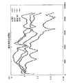
図13は頭部伝達関数を説明するための図である。人間の可聴周波数領域においてフーリエ変換して時間領域において表現した伝達関数であり、スピーカ1を人間の頭部2の正面に置いたときの頭部伝達関数を実線3で示し、スピーカ1を頭部2の右側(右耳側)に置いたときの頭部伝達関数を破線4で示し、スピーカ1を頭部2の後(後頭部側)に置いたときの頭部伝達関数を二点鎖線5で示してある。周知のように、人間は、学習効果によって頭部伝達関数を身に付けており、日常生活において、この頭部伝達関数に基づいて音源の方位を定位している。
FIG. 13 is a diagram for explaining the head-related transfer function. This is a transfer function expressed in the time domain by Fourier transform in the human audible frequency domain. The head-related transfer function when the
前述した特許文献1の発明は、ドライバが正面を向いているときの頭部伝達関数に基づいて、予め自車の正面から左右に10度間隔毎に仮想音源の方位を規定して各角度に対応した頭部伝達関数を用意して、検出した障害物の方位に対応した頭部伝達関数に基づく警報音データを選択して、これをスピーカから出力するものである。
The above-mentioned invention of
ところで、頭部伝達関数は音源と人間の頭部の向きとの相対的な関係に依存することが知られている。図14は、これを説明するための図であり、図14の(I)は、左右に離間したスピーカ1L、1Rから同一の音色を出力したときに、人間の頭部が正面を向いているとき(左右のスピーカ1L、1Rとの相対角度が45度)の頭部伝達関数によって正面に音像6が存在すると認知したと仮定すると、人間の頭部2が右に回転して図14の(II)に示すように右側のスピーカ1Rと対面すると音像の方位を認知することができなくなる。
By the way, it is known that the head-related transfer function depends on the relative relationship between the sound source and the orientation of the human head. FIG. 14 is a diagram for explaining this, and FIG. 14 (I) shows that when the same tone color is output from the
上記のように頭部伝達関数が音源と人間の頭部の向きとの相対的な関係に依存することから、特許文献1ではドライバが正面視しているときには効果的であるが、ドライバが左右に頭部の向きを変えたときにはスピーカから出力される立体音響音による音像6の定位が不能となり、ドライバはスピーカからの音を聞いたとしても障害物(危険物)の方位を定位して認知できないという問題がある。
Since the head-related transfer function depends on the relative relationship between the sound source and the orientation of the human head as described above, in
そこで、本発明の目的は、ドライバが頭部を正面視から左右に回転させたとしても、障害物(危険物)の方位に対応した音像を定位してドライバが認知することのできる車両用運転支援装置を提供することにある。 Accordingly, an object of the present invention is to drive a vehicle that allows a driver to recognize and recognize a sound image corresponding to the direction of an obstacle (dangerous object) even if the driver rotates his / her head from the front to the left or right. It is to provide a support device.
上記の技術的課題は、本発明の第1の観点によれば、
複数のスピーカを備え、該スピーカから出力される音響音を介したドライバの聴覚による車両用運転支援装置であって、
車両の周囲に存在する対象物を検出する対象物検出手段と、
該対象物検出手段により検出された対象物が自車に衝突又は接触する危険性の度合いを算出する危険度算出手段と、
該危険度算出手段により自車に衝突又は接触する所定以上の危険度が有ると判断されたときに、当該危険度を備えた対象物の方位を算出する方位算出手段と、
正面視したドライバの頭部に対して前記対象物の方位に音像が生成されるように前記複数のスピーカから出力される音響音を制御する音響制御手段とを有する出力用運転支援装置において、
ドライバの頭部の監視する頭部監視手段と、
ドライバの頭部の回転角度に応じて、前記音響制御手段による音響音を補正する音響音補正手段とを有し、
前記ドライバの頭部が正面視から左右に回転していても、該ドライバに対して前記複数のスピーカから出力される音響音によって前記対象物の方位に音像が生成可能であることを特徴とする車両用運転支援装置を提供することにより達成される。
The above technical problem is, according to the first aspect of the present invention,
A driving support device for a vehicle that includes a plurality of speakers and that is audible to the driver via acoustic sounds output from the speakers,
Object detection means for detecting objects existing around the vehicle;
A degree-of-risk calculation means for calculating a degree of risk that the object detected by the object detection means collides with or comes into contact with the own vehicle;
When it is determined by the risk level calculation means that there is a predetermined level of risk of collision or contact with the host vehicle, the direction calculation means for calculating the direction of the object having the risk level,
In the driving support apparatus for output, comprising acoustic control means for controlling the acoustic sound output from the plurality of speakers so that a sound image is generated in the direction of the object with respect to the head of the driver viewed from the front.
Head monitoring means for monitoring the head of the driver;
Acoustic sound correcting means for correcting the acoustic sound by the acoustic control means according to the rotation angle of the head of the driver,
The sound image can be generated in the direction of the object by the acoustic sound output from the plurality of speakers to the driver even if the head of the driver is rotated left and right from the front view. This is achieved by providing a vehicle driving support device.
すなわち、ドライバの頭部が正面視した状態で対象物の方位に音像が生成されるように複数のスピーカから出力される音響音を制御する音響音制御手段に対して、ドライバの頭部が正面視から左右に回転しているときに、その頭部の回転角度に応じた補正を加えることにより、ドライバの頭部が正面視から左右に回転していても、該ドライバが複数のスピーカから出力される音響音を耳にしたときに対象物の方位に音像が生成される。したがって、ドライバが頭部を正面視から左右に回転させたとしても、ドライバは複数のスピーカから出力される音響音を耳にしたときに障害物(危険物)の方位に対応した音像を定位して認知することができる。 That is, the driver's head is in front of the acoustic sound control means for controlling the acoustic sound output from the plurality of speakers so that a sound image is generated in the direction of the object in a state where the driver's head is viewed from the front. When the driver's head is rotated left and right from the front, by applying correction according to the rotation angle of the head, even if the driver's head is rotated left and right from the front, the driver outputs from multiple speakers. When an acoustic sound is heard, a sound image is generated in the direction of the object. Therefore, even if the driver rotates his / her head from the front to the left or right, when the driver hears the acoustic sound output from multiple speakers, he / she locates the sound image corresponding to the direction of the obstacle (dangerous object). Can be recognized.
同様の意図に基づいて、上記の技術的課題は、本発明の第2の観点によれば、
車両の周囲に存在する対象物を検出する対象物検出手段と、
該対象物検出手段により検出された対象物が自車に衝突又は接触する危険性の度合いを算出する危険度算出手段と、
該危険度算出手段により自車に衝突又は接触する所定以上の危険度が有ると判断されたときに、当該危険度を備えた対象物の方位を算出する方位算出手段と、
ドライバの頭部の監視する頭部監視手段と、
該頭部監視手段によりドライバの頭部が正面視から左右に回転しているときに、該ドライバの頭部の回転角度を検出する頭部角度検出手段と、
ドライバの頭部を中心に回転移動する複数の可動スピーカと、
前記頭部角度検出手段が検出した前記ドライバの頭部の左右の回転角度に対応して前記複数の可動スピーカを回転させることにより、前記ドライバの頭部が正面視から左右に回転していても、該ドライバに対して前記複数のスピーカから出力される音響音によって前記対象物の方位に音像が生成可能であることを特徴とする車両用運転支援装置を提供することにより達成される。
Based on the same intention, the above technical problem is according to the second aspect of the present invention.
Object detection means for detecting objects existing around the vehicle;
A degree-of-risk calculation means for calculating a degree of risk that the object detected by the object detection means collides with or comes into contact with the own vehicle;
When it is determined by the risk level calculation means that there is a predetermined level of risk of collision or contact with the host vehicle, the direction calculation means for calculating the direction of the object having the risk level,
Head monitoring means for monitoring the head of the driver;
A head angle detecting means for detecting a rotation angle of the head of the driver when the head of the driver is rotated left and right from the front view by the head monitoring means;
A plurality of movable speakers that rotate around the head of the driver;
Even if the driver's head is rotated from the front to the left and right by rotating the plurality of movable speakers corresponding to the rotation angles of the driver's head detected by the head angle detection means. The present invention is achieved by providing a driving support apparatus for a vehicle, wherein a sound image can be generated in the direction of the object by acoustic sounds output from the plurality of speakers to the driver.
本発明の好ましい実施の形態では、
ドライバの頭部の回転角度に対応した補正データを記憶した記憶手段を更に有し、前記音響音補正手段が、前記記憶手段から前記検出したドライバの頭部の回転角度に対応した補正データを抽出することによって前記音響制御手段による音響音を補正する。これにより、正面視からの頭部の回転角度に応じた補正を演算によることなく、予め用意して記憶手段に記憶させてあるデータを抽出して、このデータを使って補正を行うことから演算処理の負担を軽減することができる。
In a preferred embodiment of the present invention,
Storage means for storing correction data corresponding to the rotation angle of the driver's head, wherein the acoustic sound correction means extracts correction data corresponding to the detected rotation angle of the head of the driver from the storage means. By doing so, the acoustic sound by the acoustic control means is corrected. This makes it possible to extract the data prepared in advance and stored in the storage means and perform correction using this data, without performing correction according to the rotation angle of the head from the front view. The processing burden can be reduced.
複数の定置スピーカ又は複数の可動スピーカのいずれを採用したとしても、一つの態様として、複数の定置スピーカから出力される音響音による音像が、最初に車両の前方の方位となり、次いで該音像が、段階的に、対象物の方位に近づき、最終的に、音像が対象物の方位になるように制御してもよい。これによれば、ドライバの頭部が向いている方位と対象物の方位とが異なっている場合に、ドライバは、スピーカから聞こえる立体音響音の音像が段階的に対象物の方位に近づいて行くことから、この音像の移動方向にドライバの注意を誘導することができる。 Regardless of which one of a plurality of stationary speakers or a plurality of movable speakers is adopted, as one aspect, the sound image generated by the acoustic sound output from the plurality of stationary speakers is the front direction of the vehicle first, and then the sound image is Control may be performed so that the direction of the object is gradually approached and the sound image finally becomes the direction of the object. According to this, when the heading of the driver is different from the heading direction of the object, the driver gradually approaches the heading of the target object in the stereophonic sound that can be heard from the speaker. Therefore, the driver's attention can be guided in the moving direction of the sound image.
以下に、添付の図面に基づいて本発明の好ましい実施例を説明する。
第1実施例(図1〜図6):
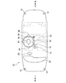
図1を参照して、自動車10は、車体の例えば四隅など適宜の箇所に、車両の周囲に存在する対象物を検知する対象物検知センサ12を備え、対象物検知センサ12によって、車両の周囲に位置する物体(例えばガードレース、家、壁、歩行者、自転車など)を検出する。対象物検知センサ12として超音波、赤外線、レーダーを利用したセンサなどを採用することができる。
Hereinafter, preferred embodiments of the present invention will be described with reference to the accompanying drawings.
First Example (FIGS. 1 to 6) :
Referring to FIG. 1, an
自動車10は、フロントウインドウの上端且つ車幅方向中央部分に、自動車10の前方を監視するための前方監視カメラ14と、ドライバの頭部16に向けて配設されたドライバ監視カメラ18とを有し、ドライバ監視カメラ18によってドライバの頭部16が監視される。図1において参照符号20はインスツルメントパネルを示し、22はハンドルを示す。
The
自動車10は、オーディオシステムの一部を構成する左右前部及び左右後方に定置した合計4個の定置スピーカ24、26、28、30が搭載されており、この4個の定置スピーカ24〜30は、実施例の車両運転支援装置32の一部を構成し、この4個の定置スピーカ24〜30を使って、対象物Oが衝突又は接触の可能性がある時に警報のメッセージ又は音響音が出力され、ドライバは定置スピーカ24〜30から出力される立体音響音によって対象物Oの方位を認知することができる。
The
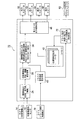
図2は、第1実施例の車両運転支援装置32の概要を示すブロック図である。車両運転支援装置32は、対象物検知センサ12、前方監視カメラ14を含む障害物検出手段34を有し、対象物検知センサ12、前方監視カメラ14からの信号によって他の車両、歩行者、二輪車、ガードレールなどの対象物Oを検出することができる。そして、検知した対象物Oが車両と接触又は衝突する危険性が大きいときには、この対象物Oつまり障害物の車両に対する方位及び距離が障害物方位及び距離算出手段36によって求められる。次いで、障害物Oの定位のための仮想音算出処理手段38によって、上記障害物方位及び距離算出手段によって求めた障害物Oの方位に対応した定位ができる仮想音の算出が実行される。この仮想音の算出は、基本頭部伝達関数つまりドライバの頭部16が基準となる方位であるスピーカに正対したときの頭部伝達関数(図3)に基づいて行われる。なお、図3では、0°(音源と正対)、90°(音源を右90°に配置)、180°(音源を背面に配置)、270°(音源を左90°に配置)の基本頭部伝達関数を示してあるが、これは単なる例示であり、例えば30°毎というように任意の角度毎に設定した頭部伝達関数を基本頭部伝達関数として採用してもよい。
FIG. 2 is a block diagram showing an outline of the vehicle driving
ドライバの頭部16がどの方向に向いているかは、ドライバ監視カメラ18からの信号に基づいて頭部回転角度算出処理手段40によって算出される。すなわち頭部回転角度算出処理手段40は、ドライバ監視カメラ18からの信号によってドライバの頭部16が、正面視から何度回転した方向に向いているかを算出する。
Which direction the
車両運転支援装置32の一部を構成するメモリ手段42には、上述した基本頭部伝達関数の他に、ドライバの頭部16が正面視の状態から右及び左に角度θで回転した状態のときの補正伝達関数が、例えば右30度、右60度、右90°・・・、左30度、左60度、左90°・・・というように所定の回転角度θ毎にデータベース化されている。
In addition to the basic head related transfer function described above, the memory means 42 constituting a part of the vehicle driving
上記補正伝達関数について説明すると、この補正伝達関数は、車両に対するドライバの頭部16の回転つまりドライバの頭部16が基準となる正面視の状態から右又は左に向きを変えているときに上記基本頭部伝達関数を補正して対象物Oの方位を定位できるようにするための関数である。図4(b)は、図4(a)に示すように、正面方向に対象物Oが存在し、左右のスピーカがドライバ頭部16を挟んで一直線上に配置されている場合における左側スピーカから出力される音についての補正伝達関数を示している。すなわち、正面に位置した音源(図中の対象物Oの方向)に仮想配置するための補正伝達関数を示す。図4(b)に図示の補正伝達関数は、ドライバ監視カメラ18によってドライバ頭部16が基準となる正面方向に対して左に90°回転していると検出されたときにメモリ手段42から左側スピーカ用として抽出される。図中の右側スピーカから出力される音についても同様に、ドライバ頭部16の後方からの音を右90°の位置に仮想定位させるための補正伝達関数を用いるため、メモリ手段42から送出される。
The correction transfer function will be described. The correction transfer function is the rotation of the driver's
図2に戻って、前述した仮想音算出処理手段38によって算出されるところの、基本頭部伝達関数に基づいてドライバの頭部16が正面視している状態を前提とした対象物Oの方位に対応した障害物を定位するために算出した仮想音は、ドライバの頭部16の回転角度θに基づいてメモリ手段42から抽出した補正伝達関数によって補正処理される。この補正処理は仮想音補正処理手段44によって実行され、この処理後の音響音信号が出力制御処理手段46から各定置スピーカ24〜30に出力される。なお、上述した説明は、スピーカから出力される音響音の基本データが予め設定されており、対象物の種類によって選択されることを前提とした説明であることは言うまでもない。
Returning to FIG. 2, the orientation of the object O based on the assumption that the driver's
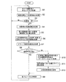
上記の処理及び制御は運転支援プログラムによって実行される。この運転支援プログラムの概要を図5のフローチャートに基づいて説明する。先ずステップS1で対象物検知センサ12や前方監視カメラ14から信号を取り込んで、撮影画像などから対象物Oの抽出処理が行われ(S2)、対象物Oが現れたときにはステップS3からS4に進んで、このステップS4で当該対象物Oが自車に衝突又は接触する危険度の算出処理が実行される。この危険度は、例えば対象物Oの種類、対象物Oと自車との距離、対象物Oの移動速度や移動方向によって自車に衝突するまでの時間を算出し、この衝突までの時間によって危険度が算出される。
The above processing and control are executed by a driving support program. The outline of this driving support program will be described based on the flowchart of FIG. First, in step S1, signals are taken from the
次にステップS5において、所定の危険度よりも高い危険度の対象物Oつまり障害物に対して、当該障害物Oの自車に対する方位の算出が行われ、この算出した方位に予め用意した立体音響音が定位できるように基本頭部伝達関数に基づく仮想音の算出が行われる(S6)。 Next, in step S5, the direction of the obstacle O relative to the subject vehicle is calculated for the object O having a higher degree of risk than the predetermined risk, that is, the obstacle, and a solid prepared in advance in the calculated direction. A virtual sound based on the basic head related transfer function is calculated so that the acoustic sound can be localized (S6).
次のステップS7においてドライバの頭部16の向き、つまりドライバの頭部16が正面視から何度回転しているかを算出し、ドライバが正面視しているとき又はほぼ正面視しているとみなせる(頭部回転角度が略ゼロ度)ときには、ステップS8からステップS9に進んで、上述した基本頭部伝達関数に基づく仮想音のデータに基づいて各スピーカ24〜30に音響音信号が出力される。正面視しているドライバは、4個のスピーカ24〜30(図1)から出力される音響音を耳にしたときに、ドライバが経験的に備えている音の方位に対する感覚に基づいて直感的にその音像を障害物Oの方向に定位して認知することができる。
In the next step S7, the direction of the
上記ステップS8においてドライバの頭部16が正面視の状態から右又は左に回転した状態にあると判断されたときにはステップS10に移行して、検出した頭部16の回転角度θに基づいて、この回転角度θに対応する補正伝達関数をメモリ手段42から抽出する。そして、次のステップS11で、補正伝達関数により各周波数に対する補正ゲインを算出し、次いで、ステップS12において、この補正ゲインによって基本頭部伝達関数に基づく各スピーカ24〜30の各周波数に対するゲインを補正する仮想音補正処理した後に、前記のステップS9に進んで、この補正した仮想音のデータに基づいて各スピーカ24〜30に音響音信号が出力される。これにより、ドライバは、正面視から右又は左に向けて頭部16を回転させた状態であっても、4個のスピーカ24〜30(図1)から出力される音響音を耳にしたときに、例え頭部16が正面視から回転した状態であったとしても、ドライバが経験的に備えている音の方位に対する感覚に基づいて直感的にその音像を障害物Oの方向に定位して認知することができる。
When it is determined in step S8 that the driver's
図6は、第1実施例の作用を概念的に説明するための図である。図6の(I)はドライバが正面視しており且つ衝突又は接触の危険性が大きい対象物Oつまり障害物である自転車が自車の前方の方位に位置している時を例示している。この場合の制御として、例えば車体前部に左右に位置している2個のスピーカ24、26に限定して例えば「チリンチリン」という自転車用に用意した音響音を出力させ且つ左右前方のスピーカ24、26から出力される音響音を制御することで、この立体音響音を聞いたドライバに対して、その音像48を障害物Oである自転車の方位に生成させることができる。
FIG. 6 is a diagram for conceptually explaining the operation of the first embodiment. (I) of FIG. 6 illustrates the case where the driver is looking in front and the object O, that is, the obstacle bicycle, is located in the front direction of the own vehicle with a high risk of collision or contact. . As control in this case, for example, limited to the two
図6の(II)はドライバの頭部が右斜め前方の方向を向いており且つ衝突又は接触の危険性が大である対象物Oつまり障害物である自転車が自車の前方の方位に位置している時を例示している。この場合の制御として、例えば車体前部の左右に位置している二個のスピーカ24、26に限定して例えば「チリンチリン」という自転車用に用意された音響音を、ドライバ頭部16の回転角度θに対応する補正伝達関数により補正した後に出力する。すなわち、図6(II)の場合は、出力するスピーカ及び各スピーカの出力タイミングが共に、図6(I)と同様になるが、出力される音質は、補正されたものが出力される(出力されるスペクトルが図6(I)と(II)とで異なる)ことになる。これによりこの立体音響音を聞いたドライバに対して、その音像48を障害物Oである自転車の方位に生成させることができる。
(II) in FIG. 6 shows that the head of the driver is directed diagonally forward right and the object O, that is, the obstacle, which has a high risk of collision or contact, is positioned in the front direction of the host vehicle. This is an example of when. As a control in this case, for example, the acoustic sound prepared for a bicycle called “tilintilin” is limited to the two
第2実施例(図7〜図11):
前述した第1実施例は、定置した複数のスピーカ24〜30に関連した実施例であるが、以下に説明する第2実施例は、機械的な構成において、ドライバの頭部16の周りで移動する複数の可動スピーカ50、52、54、56を採用している点で第1実施例とは異なる。可動スピーカ50〜56は、広指向性又は無指向性のスピーカで構成することができ、好適には、分割振動方式の平面スピーカで構成されるのがよい。
Second Example (FIGS. 7 to 11) :
The first embodiment described above is an embodiment related to a plurality of
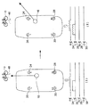
図7及び図8を参照して、車体のルーフにはドライバの頭部16の真上に、頭部16を中心とした円形ガイドレール58に4個のスピーカ50〜56が90度間隔で配設され、円形ガイドレール58は図示を省略したモータなどのアクチュエータ60(図7)によって駆動される。
7 and 8, four
4個のスピーカ50〜56は、ドライバが正面視しているときは、第1、第2のスピーカ50、52がドライバの頭部16の真横の左右に位置し、第3、第4のスピーカ54、56がドライバの頭部16の前後に位置する。そして、ドライバの頭部16が左右に回転したときには、これに追従して四個のスピーカ50〜56が円形ガイドレール58に沿って移動して第1、第2のスピーカ50、52が、正面視から回転した頭部16の真横の左右に位置し、第3、第4のスピーカ54、56がドライバの頭部16の前後に位置した状態が維持される。
When the driver is viewing the front, the four
円形ガイド58の頭部16の前方に位置する部位には、第3スピーカ54の他に平面ディスプレー62が配設され、この平面ディスプレー62は、ドライバの頭部16の左右の回転動作に追従して4個のスピーカ50〜56と一緒に移動してドライバの頭部16の正面に位置し続ける。
In addition to the
図9は、第2実施例の車両運転支援装置70の概要を示すブロック図である。なお、第2実施例の車両運転支援装置70の説明において第1実施例と同一の構成の要素には同一の参照符号を付すことによりその説明を省略し、以下に第2実施例の特徴部分について説明する。
FIG. 9 is a block diagram showing an outline of the vehicle driving
この第2実施例の車両運転支援装置70においては、頭部回転角度算出処理手段40によって検出されたドライバの頭部16の回転角度θに基づいて、スピーカ回転角度算出処理手段72によってスピーカ50〜56の回転角度が算出され、この回転角度となるようにアクチュエータ60に制御信号が出力される。これにより、ドライバの頭部16が例えば右30°の方向に向いているときには、この頭部16の回転角度と一致するようにスピーカ50〜56の位置が変位され、斜め右に向いている頭部16の左右、前方及び後方にスピーカ50〜56が位置決めされる。
In the vehicle driving
メモリ手段42には、図11に示すように、頭部16の回転角度θと対象物Oの方位θoとの差(θo―θ)に対応した基本頭部伝達関数のデータが各角度差毎にデータベース化されている。この基本頭部伝達関数のデータは各車種毎に実験により得ることが出来る。第2実施例においては、スピーカは、ドライバの頭部回転に追従し、常にドライバの頭部とスピーカは基準の位置関係が維持されるため、第1実施例に示したような補償量算出のための補正伝達関数を必要としない。すなわち、頭部の回転にスピーカを追従させることで、音響音補正が実現される。そして、頭部16の回転角度θと対象物Oの方位θoとの差(θo―θ)に対応する基本頭部伝達関数がメモリ手段42から抽出され、障害物定位のための仮想音算出処理手段38に供給される。仮想音算出処理手段38において、頭部16の回転角度θと対象物Oの方位θoとの差(θo―θ)と基本頭部伝達関数より各スピーカ50〜56の障害物を定位するための仮想音が算出されて、各スピーカ出力制御処理手段46に供給され、音響音信号が、各スピーカ50〜56に供給される。
As shown in FIG. 11, the memory means 42 stores basic head-related transfer function data corresponding to the difference (θo−θ) between the rotation angle θ of the
上記の処理及び制御の一例を図10のフローチャートに基づいて説明する。なお、第1実施例で説明した図5のフローチャートに示すステップと同一のステップには同じ参照符号を付すことによりその説明を省略し、この第2実施例での制御の特徴部分を中心に説明する。 An example of the above processing and control will be described based on the flowchart of FIG. The same steps as those shown in the flowchart of FIG. 5 described in the first embodiment are denoted by the same reference numerals, and the description thereof will be omitted. The description will focus on the features of the control in the second embodiment. To do.
図10を参照してステップS7でドライバの頭部16の向き、つまりドライバの頭部16が正面視から何度回転しているかを算出し、ドライバの頭部16の回転角度θに追従して4個の可動スピーカ50〜56が頭部16を中心に回転され、回転後の4個の可動スピーカ50〜56は、正面視している頭部16に対する相対的な位置関係と同じになるように、回転角度θの頭部16の左右及び前後に位置決めされる(S18)。
Referring to FIG. 10, in step S7, the direction of the driver's
また、ドライバの頭部16の回転角度θと対象物の方位θ0との差(θ0−θ)に立体音響を定位させるように基本頭部伝達関数に基づいて仮想音算出処理(S19)が行われ、そして、算出された仮想音となるように各スピーカに対する出力制御が行われる(S9)。
Further, a virtual sound calculation process (S19) based on the basic head-related transfer function so as to localize the stereophonic sound to the difference (θ 0 −θ) between the rotation angle θ of the driver's
図11は、第2実施例の作用を概念的に説明するための図である。図11の(I)はドライバが正面視しており且つ対象物O(自転車)が斜め右方向に出現した状態を示す。この状態では、スピーカ50〜56は、正面視している頭部16に合致させて車幅方向の左右及び車体前後方向の前後に位置決めされている。図11の(II)は、その後、ドライバが斜め右方向に、角度θ、頭部16を回転させ、また、対象物Oである自転車が接触する危険性が大きいと判断された状態を示す。スピーカ50〜56は、頭部16の回転角度θに合致した回転移動されて、頭部16の左右及び前後に位置決めされる。また、障害物Oが自転車であることから、例えば「チリンチリン」という音響音が、限定した前方のスピーカ54と右方のスピーカ50とから出力され、また前方及び右方のスピーカ50、54から出力される音響音を制御することで、この立体音響音を聞いたドライバに対して、ドライバが経験的に備えている音の方位に対する感覚に基づいて直感的にその音像48を障害物Oの方向に定位して認知することができる。
FIG. 11 is a diagram for conceptually explaining the operation of the second embodiment. (I) of FIG. 11 shows a state where the driver is looking in front and the object O (bicycle) appears diagonally to the right. In this state, the
上述した音響音の制御とは別に、ドライバの頭部16の正面に位置決めされる平面ディスプレー62には「自転車接近中」などの警告が表示される。
In addition to the above-described acoustic sound control, a warning such as “Bicycle approaching” is displayed on the
第2実施例の変形例(図12):
上記第2実施例では、音像48を障害物Oの方位と一致した方位に定位できるようにスピーカ50〜56の回転位置を設定したが、図12に示すように、最初に自車の正面の方位に音像48が生成されるように音響音を制御し、この音像48が段階的に障害物Oの方位に接近して最終的に障害物Oの方位に音像48が定位されるように制御してもよい。また、これにドライバの頭部16の回転が伴った時には、最初に頭部16の正面の方位に音像18を生成し、次いで頭部16の回転方向の動き追従して、音像48が段階的に障害物Oの方位に接近して最終的に障害物Oの方位に音像48が定位されるように制御してもよい。
Modification of the second embodiment (FIG. 12) :
In the second embodiment, the rotational positions of the
図12を参照した第2実施例の変形例は、定置した複数のスピーカ24〜30を備えた第1実施例に対しても同様に適用可能であり、前述した第1実施例において、複数の定置したスピーカ24〜30から出力される立体音響音は、最初に音像を車両に正面の方位に生成し、段階的に、音像の方位が障害物Oの方位に近づくように複数の定置したスピーカ24〜30から出力される音響音を制御し、最終的に、音像の方位が障害物Oの方位と一致するようにスピーカ24〜30から出力される音響音を制御するようにしてもよい。第1、第2実施例の変形例のいずれであっても、この制御は、ドライバの頭部16が向いている方位と対象物の方位とが異なっている場合に実行されることになるが、この制御によって、スピーカ24〜30又は50〜56から出力される音響音の音像が段階的に障害物Oの方位に近づいて行くことから、この障害物Oの方位へ向けて変位する音像によってドライバの注意を障害物Oへと誘導することができる。
The modification of the second embodiment with reference to FIG. 12 can be similarly applied to the first embodiment including a plurality of
O 対象物
10 自動車
12 対象物検知センサ(対象物検出手段)
14 前方監視カメラ(対象物検出手段)
16 ドライバの頭部
18 ドライバ監視カメラ(頭部検出手段)
24〜30 定置スピーカ
32 第1実施例の車両運転支援装置
34 障害物検出手段
36 障害物方位及び距離算出手段
38 仮想音算出処理手段(音響制御手段)
40 頭部回転角度算出処理手段
42 メモリ手段
44 仮想音補正処理手段(音響音補正手段)
46 出力制御処理手段
48 音像
50〜56 可動スピーカ
70 第2実施例の車両運転支援装置
O object 10
14 Front surveillance camera (object detection means)
16 Driver's
24 to 30
40 Head rotation angle calculation processing means 42 Memory means 44 Virtual sound correction processing means (acoustic sound correction means)
46 Output control processing means 48
Claims (5)
車両の周囲に存在する対象物を検出する対象物検出手段と、
該対象物検出手段により検出された対象物が自車に衝突又は接触する危険性の度合いを算出する危険度算出手段と、
該危険度算出手段により自車に衝突又は接触する所定以上の危険度が有ると判断されたときに、当該危険度を備えた対象物の方位を算出する方位算出手段と、
正面視したドライバの頭部に関して前記対象物の方位に音像が生成されるように前記複数のスピーカから出力される音響音を制御する音響制御手段とを有する出力用運転支援装置において、
ドライバの頭部を監視する頭部監視手段と、
該頭部監視手段によりドライバの頭部が正面視から左右に回転しているときに、該ドライバの頭部の回転角度を検出する頭部角度検出手段と、
該頭部角度検出手段により検出した前記ドライバの頭部の回転角度に応じて、前記音響制御手段による音響音を補正する音響音補正手段とを有し、
前記ドライバの頭部が正面視から左右に回転していても、該ドライバに対して前記複数のスピーカから出力される音響音によって前記対象物の方位に音像が生成可能であることを特徴とする車両用運転支援装置。 A driving support device for a vehicle that includes a plurality of speakers and that is audible to the driver via acoustic sounds output from the speakers,
Object detection means for detecting objects existing around the vehicle;
A degree-of-risk calculation means for calculating a degree of risk that the object detected by the object detection means collides with or comes into contact with the own vehicle;
When it is determined by the risk level calculation means that there is a predetermined level of risk of collision or contact with the host vehicle, the direction calculation means for calculating the direction of the object having the risk level,
In the driving support apparatus for output having an acoustic control means for controlling acoustic sounds output from the plurality of speakers so that a sound image is generated in the direction of the object with respect to the head of the driver viewed from the front,
Head monitoring means for monitoring the head of the driver;
A head angle detecting means for detecting a rotation angle of the head of the driver when the head of the driver is rotated left and right from the front view by the head monitoring means;
Acoustic sound correcting means for correcting the acoustic sound by the acoustic control means according to the rotation angle of the head of the driver detected by the head angle detecting means,
The sound image can be generated in the direction of the object by the acoustic sound output from the plurality of speakers to the driver even if the head of the driver is rotated left and right from the front view. Vehicle driving support device.
前記音響音補正手段が、前記記憶手段から前記検出したドライバの頭部の回転角度に対応した補正データを抽出することによって前記音響制御手段による音響音を補正する、請求項1に記載の車両用運転支援装置。 Storage means for storing correction data corresponding to the rotation angle of the head of the driver;
The vehicle acoustic vehicle according to claim 1, wherein the acoustic sound correcting unit corrects the acoustic sound generated by the acoustic control unit by extracting correction data corresponding to the detected rotation angle of the head of the driver from the storage unit. Driving assistance device.
該対象物検出手段により検出された対象物が自車に衝突又は接触する危険性の度合いを算出する危険度算出手段と、
該危険度算出手段により自車に衝突又は接触する所定以上の危険度が有ると判断されたときに、当該危険度を備えた対象物の方位を算出する方位算出手段と、
ドライバの頭部の監視する頭部監視手段と、
該頭部監視手段によりドライバの頭部が正面視から左右に回転しているときに、該ドライバの頭部の回転角度を検出する頭部角度検出手段と、
ドライバの頭部を中心に回転移動する複数の可動スピーカと、
前記頭部角度検出手段が検出した前記ドライバの頭部の左右の回転角度に対応して前記複数の可動スピーカを回転させることにより、前記ドライバの頭部が正面視から左右に回転していても、該ドライバに対して前記複数のスピーカから出力される音響音によって前記対象物の方位に音像が生成可能であることを特徴とする車両用運転支援装置。 Object detection means for detecting objects existing around the vehicle;
A degree-of-risk calculation means for calculating a degree of risk that the object detected by the object detection means collides with or comes into contact with the own vehicle;
When it is determined by the risk level calculation means that there is a predetermined level of risk of collision or contact with the host vehicle, the direction calculation means for calculating the direction of the object having the risk level,
Head monitoring means for monitoring the head of the driver;
A head angle detecting means for detecting a rotation angle of the head of the driver when the head of the driver is rotated left and right from the front view by the head monitoring means;
A plurality of movable speakers that rotate around the head of the driver;
Even if the driver's head is rotated from the front to the left and right by rotating the plurality of movable speakers corresponding to the rotation angles of the driver's head detected by the head angle detection means. The vehicle driving support device is characterized in that a sound image can be generated in the direction of the object by acoustic sounds output from the plurality of speakers to the driver.
Priority Applications (1)
| Application Number | Priority Date | Filing Date | Title |
|---|---|---|---|
| JP2008232922A JP5263507B2 (en) | 2008-09-11 | 2008-09-11 | Vehicle driving support device |
Applications Claiming Priority (1)
| Application Number | Priority Date | Filing Date | Title |
|---|---|---|---|
| JP2008232922A JP5263507B2 (en) | 2008-09-11 | 2008-09-11 | Vehicle driving support device |
Publications (2)
| Publication Number | Publication Date |
|---|---|
| JP2010067020A true JP2010067020A (en) | 2010-03-25 |
| JP5263507B2 JP5263507B2 (en) | 2013-08-14 |
Family
ID=42192555
Family Applications (1)
| Application Number | Title | Priority Date | Filing Date |
|---|---|---|---|
| JP2008232922A Expired - Fee Related JP5263507B2 (en) | 2008-09-11 | 2008-09-11 | Vehicle driving support device |
Country Status (1)
| Country | Link |
|---|---|
| JP (1) | JP5263507B2 (en) |
Cited By (7)
| Publication number | Priority date | Publication date | Assignee | Title |
|---|---|---|---|---|
| JP2014135694A (en) * | 2013-01-11 | 2014-07-24 | Denso Corp | On-vehicle acoustic device |
| JP2016199124A (en) * | 2015-04-09 | 2016-12-01 | 之彦 須崎 | Sound field control device and application method |
| GB2542609A (en) * | 2015-09-25 | 2017-03-29 | Nokia Technologies Oy | Differential headtracking apparatus |
| JP2017224165A (en) * | 2016-06-15 | 2017-12-21 | 矢崎総業株式会社 | Vehicular direction presentation device |
| JP2020160876A (en) * | 2019-03-27 | 2020-10-01 | 株式会社Subaru | Approach warning device of vehicle |
| WO2022196429A1 (en) * | 2021-03-15 | 2022-09-22 | ソニーグループ株式会社 | Information processing device, information processing method, and program |
| WO2023241883A1 (en) * | 2022-06-15 | 2023-12-21 | Mercedes-Benz Group AG | Method for determining the head related transfer function |
Citations (4)
| Publication number | Priority date | Publication date | Assignee | Title |
|---|---|---|---|---|
| JP2001001851A (en) * | 1999-06-16 | 2001-01-09 | Honda Motor Co Ltd | Alarm device for vehicle |
| JP2004226189A (en) * | 2003-01-22 | 2004-08-12 | Mitsubishi Electric Corp | Car navigation system |
| JP2005343431A (en) * | 2004-06-07 | 2005-12-15 | Denso Corp | Vehicular information processing system |
| JP2008129734A (en) * | 2006-11-17 | 2008-06-05 | Calsonic Kansei Corp | Solid sound image warning device |
-
2008
- 2008-09-11 JP JP2008232922A patent/JP5263507B2/en not_active Expired - Fee Related
Patent Citations (4)
| Publication number | Priority date | Publication date | Assignee | Title |
|---|---|---|---|---|
| JP2001001851A (en) * | 1999-06-16 | 2001-01-09 | Honda Motor Co Ltd | Alarm device for vehicle |
| JP2004226189A (en) * | 2003-01-22 | 2004-08-12 | Mitsubishi Electric Corp | Car navigation system |
| JP2005343431A (en) * | 2004-06-07 | 2005-12-15 | Denso Corp | Vehicular information processing system |
| JP2008129734A (en) * | 2006-11-17 | 2008-06-05 | Calsonic Kansei Corp | Solid sound image warning device |
Cited By (9)
| Publication number | Priority date | Publication date | Assignee | Title |
|---|---|---|---|---|
| JP2014135694A (en) * | 2013-01-11 | 2014-07-24 | Denso Corp | On-vehicle acoustic device |
| US9191765B2 (en) | 2013-01-11 | 2015-11-17 | Denso Corporation | In-vehicle audio device |
| JP2016199124A (en) * | 2015-04-09 | 2016-12-01 | 之彦 須崎 | Sound field control device and application method |
| GB2542609A (en) * | 2015-09-25 | 2017-03-29 | Nokia Technologies Oy | Differential headtracking apparatus |
| JP2017224165A (en) * | 2016-06-15 | 2017-12-21 | 矢崎総業株式会社 | Vehicular direction presentation device |
| JP2020160876A (en) * | 2019-03-27 | 2020-10-01 | 株式会社Subaru | Approach warning device of vehicle |
| JP7333185B2 (en) | 2019-03-27 | 2023-08-24 | 株式会社Subaru | vehicle approach warning device |
| WO2022196429A1 (en) * | 2021-03-15 | 2022-09-22 | ソニーグループ株式会社 | Information processing device, information processing method, and program |
| WO2023241883A1 (en) * | 2022-06-15 | 2023-12-21 | Mercedes-Benz Group AG | Method for determining the head related transfer function |
Also Published As
| Publication number | Publication date |
|---|---|
| JP5263507B2 (en) | 2013-08-14 |
Similar Documents
| Publication | Publication Date | Title |
|---|---|---|
| JP5263507B2 (en) | Vehicle driving support device | |
| US11091092B2 (en) | Method for robotic vehicle communication with an external environment via acoustic beam forming | |
| JP6115576B2 (en) | Vehicle travel control device | |
| EP3285241B1 (en) | System and method for processing traffic sound data to provide driver assistance | |
| US9880554B2 (en) | Misrecognition determination device | |
| US7327235B2 (en) | Alarm sound outputting device for vehicle and program thereof | |
| US8212659B2 (en) | Driving assist device for vehicle | |
| US20190299981A1 (en) | Vehicle control apparatus, a system including the same, and a method thereof | |
| JPH1116097A (en) | Operation supporting device for vehicle | |
| US11492001B2 (en) | Notification device | |
| US20170096104A1 (en) | Potential hazard indicating system and method | |
| JP6384419B2 (en) | Animal type determination device | |
| JP2001109999A (en) | Driving support device for vehicle | |
| US11774964B2 (en) | Vehicle remote instruction system | |
| CN110462701B (en) | Vehicle guidance device, method, and storage medium storing vehicle guidance program | |
| JP2007328603A (en) | Vehicle warning device | |
| JP2009154641A (en) | Drive supporting device | |
| JP2010076524A (en) | Drive support device for vehicle | |
| CN110447244B (en) | Method for providing a spatially perceptible acoustic signal to a two-wheeled vehicle rider | |
| JP2010058743A (en) | Driving assist device for vehicle | |
| JP2008250453A (en) | Drive support device and method | |
| JP2008257636A (en) | Driving support device | |
| JP2009211628A (en) | Obstacle warning device, obstacle warning method, and computer program | |
| JP2021018636A (en) | Vehicle remote instruction system | |
| JP7220027B2 (en) | Driving support device |
Legal Events
| Date | Code | Title | Description |
|---|---|---|---|
| A621 | Written request for application examination |
Free format text: JAPANESE INTERMEDIATE CODE: A621 Effective date: 20110802 |
|
| A521 | Written amendment |
Free format text: JAPANESE INTERMEDIATE CODE: A523 Effective date: 20120329 |
|
| A131 | Notification of reasons for refusal |
Free format text: JAPANESE INTERMEDIATE CODE: A131 Effective date: 20121114 |
|
| A977 | Report on retrieval |
Free format text: JAPANESE INTERMEDIATE CODE: A971007 Effective date: 20121114 |
|
| A521 | Written amendment |
Free format text: JAPANESE INTERMEDIATE CODE: A523 Effective date: 20130107 |
|
| TRDD | Decision of grant or rejection written | ||
| A01 | Written decision to grant a patent or to grant a registration (utility model) |
Free format text: JAPANESE INTERMEDIATE CODE: A01 Effective date: 20130403 |
|
| A61 | First payment of annual fees (during grant procedure) |
Free format text: JAPANESE INTERMEDIATE CODE: A61 Effective date: 20130416 |
|
| R150 | Certificate of patent or registration of utility model |
Free format text: JAPANESE INTERMEDIATE CODE: R150 Ref document number: 5263507 Country of ref document: JP Free format text: JAPANESE INTERMEDIATE CODE: R150 |
|
| LAPS | Cancellation because of no payment of annual fees |