JP2010066583A - Fixing device and image forming apparatus - Google Patents
Fixing device and image forming apparatus Download PDFInfo
- Publication number
- JP2010066583A JP2010066583A JP2008233550A JP2008233550A JP2010066583A JP 2010066583 A JP2010066583 A JP 2010066583A JP 2008233550 A JP2008233550 A JP 2008233550A JP 2008233550 A JP2008233550 A JP 2008233550A JP 2010066583 A JP2010066583 A JP 2010066583A
- Authority
- JP
- Japan
- Prior art keywords
- fixing
- heating
- fixing belt
- paper
- paper width
- Prior art date
- Legal status (The legal status is an assumption and is not a legal conclusion. Google has not performed a legal analysis and makes no representation as to the accuracy of the status listed.)
- Granted
Links
Images


Classifications
-
- G—PHYSICS
- G03—PHOTOGRAPHY; CINEMATOGRAPHY; ANALOGOUS TECHNIQUES USING WAVES OTHER THAN OPTICAL WAVES; ELECTROGRAPHY; HOLOGRAPHY
- G03G—ELECTROGRAPHY; ELECTROPHOTOGRAPHY; MAGNETOGRAPHY
- G03G15/00—Apparatus for electrographic processes using a charge pattern
- G03G15/20—Apparatus for electrographic processes using a charge pattern for fixing, e.g. by using heat
- G03G15/2003—Apparatus for electrographic processes using a charge pattern for fixing, e.g. by using heat using heat
- G03G15/2014—Apparatus for electrographic processes using a charge pattern for fixing, e.g. by using heat using heat using contact heat
- G03G15/2039—Apparatus for electrographic processes using a charge pattern for fixing, e.g. by using heat using heat using contact heat with means for controlling the fixing temperature
- G03G15/2042—Apparatus for electrographic processes using a charge pattern for fixing, e.g. by using heat using heat using contact heat with means for controlling the fixing temperature specially for the axial heat partition
-
- G—PHYSICS
- G03—PHOTOGRAPHY; CINEMATOGRAPHY; ANALOGOUS TECHNIQUES USING WAVES OTHER THAN OPTICAL WAVES; ELECTROGRAPHY; HOLOGRAPHY
- G03G—ELECTROGRAPHY; ELECTROPHOTOGRAPHY; MAGNETOGRAPHY
- G03G2215/00—Apparatus for electrophotographic processes
- G03G2215/00362—Apparatus for electrophotographic processes relating to the copy medium handling
- G03G2215/00535—Stable handling of copy medium
- G03G2215/00717—Detection of physical properties
- G03G2215/00734—Detection of physical properties of sheet size
Landscapes
- Physics & Mathematics (AREA)
- General Physics & Mathematics (AREA)
- Fixing For Electrophotography (AREA)
Abstract
Description
本発明は、記録媒体(例えば、転写紙)に転写されたトナー画像を定着する定着装置および画像形成装置に関するものである。 The present invention relates to a fixing device and an image forming apparatus for fixing a toner image transferred to a recording medium (for example, transfer paper).
電子写真方式の画像形成装置においては、一般に加熱加圧方式の定着装置が用いられている。前記定着装置は、例えば、内部に熱源を有する定着ベルトと加圧ローラとを備え、定着ベルトと加圧ローラとの圧接部(ニップ部)を通過する転写紙上の未定着トナー象を加熱加圧して定着するようになっている。 In an electrophotographic image forming apparatus, a heating and pressing type fixing device is generally used. The fixing device includes, for example, a fixing belt having a heat source therein and a pressure roller, and heats and presses an unfixed toner image on a transfer sheet passing through a pressure contact portion (nip portion) between the fixing belt and the pressure roller. And become established.
前記定着装置においては、例えば、定着ベルト幅よりも小さなサイズの転写紙に連続して定着処理を行うと、熱源から発せられた熱エネルギーは転写紙が通過する定着ベルトの中央部で消費されるのに対し、定着ベルトの端部では消費されずに温度の過昇を招いてしまう。定着ベルトの端部の温度過昇によって、定着ベルトおよび加圧ローラの表層の劣化が早まる。また、熱源から発せられた熱エネルギーを転写紙の通過領域(通紙領域)ばかりでなく、非通紙領域にも供給することから、エネルギーを効率よく使用しているとは言い難い。 In the fixing device, for example, when a fixing process is continuously performed on transfer paper having a size smaller than the fixing belt width, the heat energy generated from the heat source is consumed at the center of the fixing belt through which the transfer paper passes. On the other hand, the temperature is not consumed at the end of the fixing belt and the temperature rises. Deterioration of the surface layer of the fixing belt and the pressure roller is accelerated due to an excessive temperature rise at the end of the fixing belt. Further, since the heat energy generated from the heat source is supplied not only to the transfer paper passing area (paper passing area) but also to the non-paper passing area, it cannot be said that the energy is efficiently used.
これに対し、従来の定着装置には、加熱ローラと加圧ローラとを備え、加熱ローラ内部に、熱源(例えば、ハロゲンランプ)と、ハロゲンランプを囲む円筒状の回転遮光部材と、回転遮光部材の外側に配置された固定スリーブと、固定スリーブの外側に配置された回転スリーブと、を備え、固定スリーブには加熱ローラの幅方向(軸方向)に延びる矩形スリットを形成し、回転遮光部材には一辺が加熱ローラの軸方向に延びる三角スリットを形成しているものがある(例えば、特許文献1参照)。この場合、転写紙の紙幅に応じて回転遮光部材を回転させ、矩形スリットと三角スリットとを適宜重ねて開口部の大きさを調節することにより、開口部を通してハロゲンランプの光を回転スリーブ内周の加熱領域(通紙領域に相当する)に照射することが可能となる。
しかしながら、従来の定着装置においては、熱源と回転スリーブとの間に固定スリーブおよび回転遮光部材が介在するために、熱源から発する熱エネルギーの大部分が固定スリーブおよび回転遮光部材の昇温のために消費され、回転スリーブに対して必要十分な熱エネルギーを効率よく供給することが難しいという問題があった。また、開口部の紙幅方向の大きさを変更するために、三角スリットの転写紙搬送方向サイズに対して矩形スリットの転写紙搬送方向サイズを小さくしているので、転写紙搬送方向(紙幅方向と垂直な方向)において開口部の大きさが制限されるという問題があった。さらに、前述のように転写紙搬送方向の大きさが制限された開口部(矩形スリットと三角スリットとが重なる部分)から回転スリーブに対して必要十分な熱エネルギーを与えるためには大容量の熱源を要するために、定着装置が大型化してエネルギー消費が増大するという問題があった。 However, in the conventional fixing device, since the fixed sleeve and the rotating light shielding member are interposed between the heat source and the rotating sleeve, most of the heat energy generated from the heat source is for increasing the temperature of the fixing sleeve and the rotating light shielding member. There is a problem that it is consumed and it is difficult to efficiently supply necessary and sufficient heat energy to the rotating sleeve. Further, in order to change the size of the opening in the paper width direction, the size of the transfer paper transport direction of the rectangular slit is made smaller than the size of the transfer paper transport direction of the triangular slit. There is a problem that the size of the opening is limited in the vertical direction). Furthermore, as described above, a large-capacity heat source is required to give necessary and sufficient heat energy to the rotating sleeve from the opening (the portion where the rectangular slit and the triangular slit overlap) whose size in the transfer paper conveyance direction is limited. Therefore, there is a problem that the fixing device is enlarged and energy consumption is increased.
本発明は、従来の問題を解決するためになされたもので、各種の記録媒体の紙幅に対応しながら、エネルギー消費を抑制することのできる定着装置および画像形成装置を提供することを目的とする。 SUMMARY An advantage of some aspects of the invention is that it provides a fixing device and an image forming apparatus capable of suppressing energy consumption while accommodating paper widths of various recording media. .
(1)本発明の定着装置は、定着部材と、前記定着部材と対向してニップ部を形成する加圧部材と、前記定着部材の表面とは非接触状態で前記定着部材を加熱する加熱手段と、を備え、前記ニップ部を通過する記録媒体に未定着トナー画像を定着する定着装置において、通紙される記録媒体の紙幅情報を検知する紙幅情報検知手段と、前記加熱手段により加熱される定着部材の加熱領域を、前記紙幅情報検知手段が検知した情報に基づいて可変する加熱領域可変手段と、を備え、前記加熱領域可変手段が、前記定着部材と前記加熱手段との間を紙幅方向に移動して加熱領域を可変する構成を有している。 (1) The fixing device of the present invention includes a fixing member, a pressure member that forms a nip portion facing the fixing member, and a heating unit that heats the fixing member in a non-contact state with the surface of the fixing member. And a paper width information detecting means for detecting paper width information of the recording medium to be passed through, and a heating means for fixing the unfixed toner image on the recording medium passing through the nip portion. A heating region variable unit that varies a heating region of the fixing member based on information detected by the paper width information detection unit, and the heating region variable unit includes a space between the fixing member and the heating unit in a paper width direction. And the heating area is variable.
この構成によれば、加熱領域可変手段が定着部材と加熱手段との間を記録媒体の紙幅方向に移動して加熱領域を可変するので、記録媒体の紙幅に応じて加熱領域を変更することができる。また、加熱領域可変手段は記録媒体の紙幅方向に移動するので、例えば、前述したように円筒状の回転遮光部材を軸周りに回転させ、回転遮光部材に形成された三角スリットと回転遮光部材の外側を囲む固定スリーブに形成された矩形スリットとを適宜重ねて開口部の大きさを調節する場合に比べ、転写紙搬送方向において開口部の大きさが制限されることはない。したがって、加熱領域可変手段は定着処理に必要十分なように加熱領域を変更することができる。また、適切な加熱領域とすることよって定着部材および押圧部材を効率的に加熱すると共に、加熱手段の大型化を抑制することができる。 According to this configuration, since the heating area varying means moves in the paper width direction of the recording medium between the fixing member and the heating means to change the heating area, the heating area can be changed according to the paper width of the recording medium. it can. Further, since the heating region varying means moves in the paper width direction of the recording medium, for example, as described above, the cylindrical rotating light shielding member is rotated around the axis, and the triangular slit formed on the rotating light shielding member and the rotating light shielding member Compared with the case where the size of the opening is adjusted by appropriately overlapping the rectangular slit formed in the fixed sleeve surrounding the outside, the size of the opening is not limited in the transfer paper conveyance direction. Therefore, the heating region changing means can change the heating region so as to be necessary and sufficient for the fixing process. In addition, the fixing member and the pressing member can be efficiently heated and an increase in the size of the heating unit can be suppressed by setting an appropriate heating region.
(2)また、本発明の定着装置において、前記加熱領域可変手段は、前記定着部材の加熱領域が記録媒体の紙幅に比べて紙幅方向に拡がるよう、前記加熱領域を可変する構成を有している。 (2) Further, in the fixing device of the present invention, the heating area varying means has a configuration in which the heating area is varied so that the heating area of the fixing member expands in the paper width direction as compared with the paper width of the recording medium. Yes.
(3)また、本発明の定着装置において、前記定着部材の内部に、前記加熱手段と、一面が前記加熱手段と対向すると共に他の一面が前記定着部材と対向する前記加熱領域可変手段と、一面が前記加熱手段と対向すると共に他の一面が前記定着部材の裏面に当接して前記定着部材を前記加圧部材に押圧する押圧部材と、を設ける構成を有している。 (3) Further, in the fixing device of the present invention, inside the fixing member, the heating unit, the heating region varying unit having one surface facing the heating unit and the other surface facing the fixing member, And a pressing member that presses the fixing member against the pressing member while one surface faces the heating unit and the other surface contacts the back surface of the fixing member.
(4)また、本発明の定着装置において、前記加熱領域可変手段は、板状の部材によって形成された複数の板状部材と、前記各板状部材を相対的に紙幅方向へ移動可能な移動手段と、を有し、前記移動手段によって前記各板状部材が紙幅方向で離間するよう移動されることにより、前記定着部材と前記加熱手段との間に形成された開口部の大きさが調整され、前記加熱領域を可変する構成を有している。 (4) Further, in the fixing device of the present invention, the heating region varying means includes a plurality of plate-like members formed by plate-like members and a movement that can move the plate-like members relatively in the paper width direction. And the size of the opening formed between the fixing member and the heating means is adjusted by moving the plate-like members apart in the paper width direction by the moving means. The heating area is variable.
(5)また、本発明の定着装置において、前記加熱領域可変手段は、複数の開口部が紙幅方向に形成されると共に重ねて配置された複数の板状部材を有し、前記板状部材同士が相対的に紙幅方向へ移動することによって前記複数の板状部材の前記各開口部が重複して形成された重複開口領域の大きさが調整され、前記加熱領域を可変する構成を有している。 (5) Further, in the fixing device of the present invention, the heating region varying means includes a plurality of plate-like members which are arranged in a stacked manner while a plurality of openings are formed in the paper width direction, and the plate-like members are Has a configuration in which the size of the overlapping opening region formed by overlapping each opening of the plurality of plate-like members is adjusted by moving in the paper width direction relatively, and the heating region is variable. Yes.
(6)さらに、本発明の画像形成装置は、前記記録媒体にトナー画像を形成する画像形成手段と、前記画像形成手段により形成された未定着トナー画像を前記記録媒体に定着する定着手段と、を備え、前記定着手段として(1)から(5)のいずれかに記載の定着装置を用いる構成を有している。 (6) Further, the image forming apparatus of the present invention includes an image forming unit that forms a toner image on the recording medium, a fixing unit that fixes an unfixed toner image formed by the image forming unit to the recording medium, And the fixing device according to any one of (1) to (5) is used as the fixing unit.
本発明は、定着部材と加熱手段との間を記録媒体の紙幅方向に移動して前記定着部材の加熱領域を可変する加熱領域可変手段を設けることにより、各種の記録媒体の紙幅に対応しながら、エネルギー消費を抑制するという効果を有する定着装置を提供することができる。 The present invention provides a heating area variable means for changing the heating area of the fixing member by moving in the paper width direction of the recording medium between the fixing member and the heating means, while corresponding to the paper width of various recording media. A fixing device having an effect of suppressing energy consumption can be provided.
以下、本発明の定着装置を備えた画像形成装置の実施の一形態としての定着ユニットを備えた複写機について、図面を用いて説明する。 Hereinafter, a copying machine including a fixing unit as an embodiment of an image forming apparatus including a fixing device according to the present invention will be described with reference to the drawings.
[第1の実施の形態]
図1〜図5に本発明の第1の実施の形態としての複写機を示す。図1は、本発明の第1の実施の形態としての複写機の全体構成を示す断面図である。図2は、本発明の第1の実施の形態としての定着ユニットの要部を示す断面図である。図3は、本発明の第1の実施の形態としての遮蔽板の構成を示す平面図および断面図である。図4は、本発明の第1の実施の形態としての遮蔽板の開閉動作を説明する図である。図5は、本発明の第1の実施の形態としての複写機の制御系を示すブロック図である。
[First Embodiment]
1 to 5 show a copying machine as a first embodiment of the present invention. FIG. 1 is a cross-sectional view showing the entire configuration of a copying machine as a first embodiment of the present invention. FIG. 2 is a cross-sectional view showing a main part of the fixing unit according to the first embodiment of the present invention. FIG. 3 is a plan view and a cross-sectional view showing the configuration of the shielding plate as the first embodiment of the present invention. FIG. 4 is a diagram illustrating the opening / closing operation of the shielding plate according to the first embodiment of the present invention. FIG. 5 is a block diagram showing a control system of the copying machine as the first embodiment of the present invention.
図1において、カラー印刷可能な複写機202の本体上面には透光性部材からなるコンタクトガラス43が設けられており、このコンタクトガラス43に隣接する本体の上面にはコンタクトガラス43よりも小面積の透光性部材からなるスリットガラス42が設けられている。
In FIG. 1, a
また、複写機202の上部には自動原稿搬送装置(以下、ADFともいう)201が設けられており、ADF201は図示しないヒンジ機構を介し、コンタクトガラス43に対して開閉自在となっている。
Further, an automatic document feeder (hereinafter also referred to as ADF) 201 is provided on the upper portion of the
ADF201は、原稿テーブル12に載置された原稿dを取り出し、1枚ずつ分離して読取位置へ搬送すると共に、読取後の原稿dを原稿排紙トレイ28、29に排紙する。給紙ベルト39および分離ローラ40は、原稿テーブル12から取り出された原稿dを1枚ずつ分離して給送(搬送)するようになっている。反転ローラ41等の搬送ローラは、原稿dをスリットガラス42上の読取位置へ搬送するようになっている。
The ADF 201 takes out the documents d placed on the document table 12, separates them one by one and conveys them to the reading position, and discharges the documents d after reading onto the
なお、原稿長さセンサ30、31(反射型センサまたは、原稿1枚でも検知可能なアクチュエータ・タイプのセンサが用いられる)は、原稿dの搬送方向の概略長さを判定するように配置されている。ADFコントローラ101(図5参照)は、原稿長さセンサ30、31からの信号に基づいて、少なくとも同一原稿サイズの縦か横かを判断するようになっている。
一方、複写機202の上面のコンタクトガラス43の下方には、画像読取部としてのスキャナユニット301が設けられており、スキャナユニット301はCCDイメージセンサを用いた縮小光学系を有している。スキャナユニット301によって読取られた画像情報は書込みユニット3(図5参照)によって各色(Y、M、C、K)用の感光体ドラム1Y、1M、1C、1Kに照射されるようになっている。
On the other hand, a
スキャナユニット301は、コンタクトガラス43またはスリットガラス42上の原稿(または原稿束)dを照明する光源と、原稿dから反射された光をそれぞれ反射する第1ミラー、第2ミラー、第3ミラーと、第3ミラーから反射された光をCCDイメージセンサに結像するレンズと、レンズによって結像された光を電気信号に変換するCCDイメージセンサと、を備えている。
The
光源および第1ミラーは図示していない第1走行体に取付けられているとともに、第2ミラーおよび第3ミラーは図示していない第2走行体に取付けられている。第1走行体および第2走行体は、コンタクトガラス43およびスリットガラス42の下方において、その両側部下方に配設されたガイドレール(不図示)に沿って図1中、左右に移動するようになっている。
The light source and the first mirror are attached to a first traveling body (not shown), and the second mirror and the third mirror are attached to a second traveling body (not shown). The first traveling body and the second traveling body move to the left and right in FIG. 1 along guide rails (not shown) disposed below both side portions below the
そして、第1走行体および第2走行体は、コンタクトガラス43に載置された原稿を読取るときには、コンタクトガラス43の下方で図1中、左右方向に移動され、スリットガラス42を通過する原稿を読取るときには、スリットガラス42の下方で停止される。画像読取部(スキャナユニット)301は、原稿に表示された画像(文字(テキスト)、図形、写真等を含む)を読取ることができる。
When the first traveling body and the second traveling body read a document placed on the
レーザ装置3Y、3M、3C、3Kは、スキャナユニット301によって読取った画像情報に応じて光変調した4色のレーザ光を、帯電させた感光体ドラム1Y、1M、1C、1Kの表面に照射(露光)するようになっている。
The
感光体ドラム1Y、1M、1C、1Kの周囲には、感光体ドラムと共に画像形成手段を構成する現像装置4Y、4M、4C、4K、転写ベルト6、クリーニング装置8Y、8M、8C、8K、帯電装置2Y、2M、2C、2K、図示しない除電装置等が設けられている。帯電装置2Y、2M、2C、2Kはプラス電荷のコロナ放電をグリッドにより制御して感光体ドラム1Y、1M、1C、1Kの表面を一定電位に帯電させるようになっている。
Around the
レーザ装置3Y、3M、3C、3Kは一定電位に帯電された感光体ドラム1Y、1M、1C、1K上に画像情報を含んだレーザ光を照射して感光体ドラム上のマイナス電荷を除去して静電潜像を形成する。
The
現像装置4Y、4M、4C、4Kは感光体ドラム上のマイナス電荷を除去された部分にマイナスに帯電されたトナーを付着させて可視像(未定着トナー画像)を形成する。転写ベルト6にはプラスのバイアスが印加されており、この転写ベルト6はマイナスに帯電された可視像を記録媒体としての転写紙(用紙)に転写して搬送するようになっている。
The developing
クリーニング装置8Y、8M、8C、8Kはクリーニングブレードを備えており、感光体ドラム1Y、1M、1C、1Kに残ったトナーを掻き落とすようになっている。除電装置はLEDを点灯させることにより感光体ドラム1Y、1M、1C、1Kの残留電荷を除去して次の転写紙に新たな画像を形成するための準備を行う。
The
また、複写機202の本体内にはそれぞれ異なるサイズの転写紙pが収納された給紙カセット20が設けられている。給紙カセット20に収納された転写紙pは給紙ベルト21によって給紙され、給紙ベルト21に摺接し、分離方向に回転するリバースローラによって分離される。分離された転写紙は、給紙ローラ22を介してレジストローラ23に搬送され、レジストローラ23によってタイミングを取られて転写ローラ7Aと転写ベルト6のニップ部に搬送される。ここで、前述のように転写ベルト6から転写紙に未定着トナー画像が転写される。
Further, in the main body of the copying
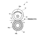
未定着トナー画像が転写された転写紙は定着ユニット9に搬送され、定着ユニット9によりトナーが溶解されると共に未定着トナー画像が転写紙に定着される。定着ユニット9は、熱源93(図2参照)を内蔵した定着ベルト91と加圧ローラ94とを備え、双方のニップ部Nに転写紙を通紙しながら定着処理(加熱加圧)を行うようになっている。
The transfer paper on which the unfixed toner image has been transferred is conveyed to the fixing
図2において、定着ユニット9は、外部ローラにより連れ回って周方向へ移動する定着ベルト91と、定着ベルト91に圧接して駆動回転する加圧ローラ94と、を有する。定着ベルト91は、可撓性を有する無端ベルトであって、定着ベルト91内部に固設された熱伝導体92上を摺動するようになっている。加圧ローラ94は、長手方向において定着ベルト91よりも短く、弾性層94bが定着ベルト91に圧接している。定着ベルト91と加圧ローラ94との接触部は平坦なニップ部Nを形成している。
In FIG. 2, the fixing
定着ベルト91は、ニッケルやステンレス(SUS)等の金属ベルト、耐熱ゴム材料、あるいはポリイミド等の耐熱樹脂材料を用いて形成されている。定着ベルト91の表面には、例えば、PFA樹脂層、PTFE樹脂層等の離型層が形成され、被定着材としての転写紙上の未定着トナーが付着しないようになっている。
The fixing
定着ベルト91内には、ヒータからなる熱源93と、熱源93による定着ベルト91の加熱領域(図4参照)に対応する開口部を形成する遮蔽板95aと、熱源93の輻射熱を定着ベルト91に伝導すると共に定着ベルト91を加圧ローラ94に押し付ける熱伝導体92と、を有する。定着ベルト91の裏面(内周面)は、熱源93の輻射熱を効率よく吸収するために例えば、黒色に着色されている。
In the fixing
遮蔽板95aは、2枚の遮蔽板95a1、95a2からなり、双方が紙幅方向に移動可能となっている。2枚の遮蔽板95a1、95a2は、アルミ系材料によって定着ベルト91の周方向に曲成されている。また、2枚の遮蔽板95a1、95a2の一面(図中、下面)が熱源93に対向し、他の一面(図中、上面)が定着ベルト91の内周(図中、上部)に対向している。前記一面には、例えば、アルミ系材料によって熱反射率が95%以上の光沢面が形成されている。また、前記他の一面には、例えば、耐熱樹脂層、耐熱ゴム層またはセラミック層が形成され、さらに耐熱樹脂層、耐熱ゴム層またはセラミック層の内部には真空断熱層が形成されている。真空断熱層の内圧は、例えば、大気圧の1/500以下としている。
The shielding
ここでは、2枚の遮蔽板95a1、95a2を離接させることにより、熱源93の輻射熱を定着ベルト91の加熱領域に供給するための開口部を形成すると共に、開口の大きさおよび位置を段階的に調整するようになっている。また、2枚の遮蔽板95a1、95a2の他の一面(曲成された下凹面)は、熱伝導体92に向けて熱源93の輻射熱を反射する。
Here, by opening and closing the two
熱伝導体92は、アルミ系材料(熱伝導率236W/m・k)等、定着ベルト91に比べて熱伝導率の高い材料で、断面半円形に曲成されて固定されている。また、熱伝導体92は、一面(図中、上面)が熱源93および定着ベルト91の内周の一部に対向し、他の一面(図中、下面)が定着ベルト91の内周(図中、下部)に接している。熱伝導体92の表面(図中、上面)は、熱源93の輻射熱を効率よく吸収するために例えば、黒色に着色されている。なお、熱伝導体92の断面は半円環形であるが、これに限らず、ニップ部Nに相当する部位が平面あるいは凹形状であってもよい。この場合、転写紙の分離性が向上する。
The
なお、定着ベルト91の外部のニップ部N近傍には図示していない温度センサを設けている。温度センサによって検知されたニップ部Nの温度情報はコントローラ300(図5参照)に送られる。
A temperature sensor (not shown) is provided in the vicinity of the nip portion N outside the fixing
加圧ローラ94は、金属ローラ94aの外周に弾性層94bを設けた構成を有している。弾性層94bは、例えば、シリコーンゴム層からなる。弾性層94bの表面には離型性を得るためにフッ素系樹脂層(例えば、PFA樹脂層、PTFE樹脂層)が形成されている。加圧ローラ94は、駆動モータ等の駆動源からギヤ、プーリ等の駆動伝達手段を介して駆動力が伝達され、図中、反時計方向に回転するようになっている。また、加圧ローラ94は、スプリング等によって定着ベルト91に押し付けられ、弾性層94bが押し潰されて、ニップ部Nに所定のニップ幅が形成されている。
The
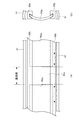
図3に示すように、定着ベルト91内には、紙幅方向に延在する2本のレール95bが設けられている。2枚の遮蔽板95a1、95a2は2本のレール95bに案内されて紙幅方向(図中、左右方向)に移動するようになっている。2枚の遮蔽板95a1、95a2を紙幅方向に移動させるための駆動手段として、例えば、電磁コイル、プランジャ等を有するソレノイド機構が2つ設けられている。2つのソレノイド機構の作動(例えば、ソレノイドのオンまたはオフ)によって2枚の遮蔽板95a1、95a2が離隔することにより、双方の間に開口部95cが形成される。2本のレール95bの対向間隔は一定であるため、開口部95cの用紙搬送方向の大きさは一定である。一方、2枚の遮蔽板95a1、95a2の移動量に応じて開口部95cの紙幅方向の大きさが変化する。なお、開口を閉塞する際、遮蔽板95a1、95a2が衝突して損傷するのを回避するため、2本のレール95bのレール溝内に図示していないストッパ(例えば、凸部材)を設けている。
As shown in FIG. 3, two
ここでは、開口部95cの紙幅方向の大きさが、転写紙が前記ニップ部Nを通るときの通紙幅より大きくなるようにしている。したがって、開口部95cを通して熱源93の輻射熱を定着ベルト91の内周に供給するとき、輻射熱によって加熱される加熱領域(図4参照)の紙幅方向の大きさも通紙幅より大きくなる。なお、加熱領域は、開口部95cを通して熱源93の輻射熱が直接供給される、定着ベルト91の内周の領域(範囲)である。また、通紙領域は、転写紙pが通過するニップ部Nの紙幅内の領域である。
Here, the size of the
図4(a)に示すように、小サイズ(例えば、最小サイズ)の転写紙p1を搬送する場合、前記ソレノイド機構の作動によって2枚の遮蔽板95a1、95a2が紙幅方向(反対方向)に移動して離隔し、小サイズ用の大きさの開口部95cが形成されるようになっている。熱源93の輻射熱は開口部95cを通して定着ベルト91の内周の加熱領域に供給される。開口部95cの紙幅方向の大きさは転写紙p1の紙幅より大きいので、定着ベルト91の内周の加熱領域の紙幅方向の大きさも転写紙p1の紙幅(通紙幅に相当する)より大きい。したがって、加熱領域の紙幅方向端部にも必要十分な熱が供給され、転写紙を均一に加熱することが期待される。
As shown in FIG. 4 (a), the small size (e.g., minimum size) when conveying the transfer sheet p 1 of the
図4(b)に示すように、大サイズ(例えば、最大サイズ)の転写紙p2を搬送する場合、前記ソレノイド機構の作動によって2枚の遮蔽板95a1、95a2が紙幅方向(反対方向)に移動して離隔し、大サイズ用の大きさの開口部95cが形成されるようになっている。熱源93の輻射熱は開口部95cを通して定着ベルト91の内周の加熱領域に供給される。開口部95cの紙幅方向の大きさは転写紙p2の紙幅より大きいので、定着ベルト91の内周の加熱領域の紙幅方向の大きさも転写紙p2の紙幅(通紙幅に相当する)より大きい。したがって、加熱領域の紙幅方向端部にも必要十分な熱が供給され、転写紙を均一に加熱することが期待される。
As shown in FIG. 4 (b), large size (e.g., the maximum size) When a transfer sheet is conveyed p 2, the two
なお、図4(a)、(b)において、定着ベルト91が熱伝導体92との接触部位(ニップ部に相当する)に向けて回動するのに伴い、前記加熱領域は紙幅方向と垂直な方向に拡大することになる。また、2枚の遮蔽板95a1、95a2の開口していない部分(非開口部)では、熱源93の輻射熱が遮蔽板95a1、95a2に供給される。供給された輻射熱の一部は遮蔽板の下面によって反射され、熱伝導体92に供給される。また、熱伝導体92に対して熱源93の輻射熱が直接、供給される。熱伝導体92に供給された熱は、熱伝導体92と定着ベルト91との接触部位(前記ニップ部を含む)から定着ベルト91に伝導される。
4A and 4B, as the fixing
さらに、大サイズの転写紙p2を搬送する場合の他の実施の形態を図4(c)に示す。 Further, it is shown in FIG. 4 (c) of another embodiment of the case of conveying the transfer sheet p 2 of large size.
図4(c)に示すように、大サイズの転写紙p2を搬送する場合、前記ソレノイド機構を作動させず、2枚の遮蔽板95a1、95a2が当接する(開口部95cが閉塞される)ように制御してもよい。この場合、開口部95cが形成されないために、熱源93の輻射熱は定着ベルト91の内周の加熱領域(図4(b)参照)に供給されない。熱源93の輻射熱は全て遮蔽板95a1、95a2および熱伝導体92に供給される。遮蔽板95a1、95a2に輻射された熱の一部は遮蔽板の下面によって反射され、熱伝導体92に供給される。熱伝導体92に供給された熱は、熱伝導体92と定着ベルト91との接触部位(前記ニップ部を含む)から定着ベルト91に伝導される。少なくとも、前記ニップ部Nにおいて熱伝導体92の紙幅方向の大きさは転写紙p2の紙幅より大きい。よって、定着ベルト91を介して転写紙p2の紙幅方向端部にも必要十分な熱が供給され、転写紙全体が均一に加熱されることが期待される。また、2枚の遮蔽板95a1、95a2の移動を伴わないので、移動に係る制御が不要となる。
As shown in FIG. 4 (c), when a transfer sheet is conveyed p 2 of large size, without operating the solenoid mechanism, the two
図5に示すように、複写機202の制御部は、ADF201のADFコントローラ101と、複写機本体のコントローラ300と、画像形成用のエンジン305と、エンジン305を制御するエンジン制御ボード304と、各種モードの設定や動作開始指示などを行うための操作パネル25と、を有する。コントローラ300とADFコントローラ101とは、インタフェース107を介して必要データや制御信号を送受信するようになっている。コントローラ300とエンジン305およびエンジン制御ボード304とは、エンジン制御ボード304の入出力インタフェース(I/O)60を介して信号の授受を行っている。コントローラ300とスキャナユニット301とは、インタフェースを介して画像データや制御信号を送受信するようになっている。
As shown in FIG. 5, the control unit of the
また、エンジン305は、レーザダイオード(LD)やポリゴンモータなどを含む書込みユニット3と、定着系、現像系、駆動系のエンジンシーケンスを司るシーケンス機器群17と、搬送路上の搬送状態やシーケンス状態をチェックするセンサ群54と、を有する。前記駆動系には、転写ベルト6のベルトローラを回転駆動するためのベルト搬送モータ、遮蔽板95aを紙幅方向に移動するためのソレノイド機構等が含まれる。センサ群54には前記温度センサが含まれる。前記温度センサは、定着ベルト91と加圧ローラ94のニップ部N近傍の温度検知に係るものである。
The
また、エンジン制御ボード304には、ROM309のプログラム、操作パネル25からのモード指示、コントローラ300からのコマンド(あるいは、これに付属する必要情報)などによってエンジン全体を制御するCPU307と、このCPU307のワークメモリあるいは入力データのインプットバッファとして用いられるRAM308と、エンジン305の制御プログラムが格納されているROM309と、エンジン305のエラー履歴や操作パネル25からのモード指示の内容などを記憶するための不揮発性メモリ(EEPROM)310と、エンジン制御のモードを設定するための切替スイッチ(DIP/SW)311と、を有する。
The
一方、コントローラ300とホストコンピュータ(ホスト)16とは、入出力インタフェース15を介して接続されており、画像形成部302とホスト16との間で必要データや制御信号を送受信する通信システムが構築されている。
On the other hand, the
また、ADFコントローラ101は、原稿長さセンサ30、31等のセンサ群53と、各種ローラ等の機構部の駆動を行う駆動部(駆動モータ、モータドライバ等)120と、に接続されている。ADFコントローラ101は、センサ群53からの信号および複写機本体側のコントローラ300からの制御信号に基づいて、コントローラ300を介してスキャナユニット301に対して読取タイミングを示すタイミング信号を送出する。前記タイミング信号により、露光のための光源を点灯/消灯させるようになっている。
The
なお、コントローラ300は、ADFコントローラ101またはホスト16を介してプリント対象の転写紙の紙幅を検出するようになっている。あるいは、操作パネル25の操作に基づいて紙幅情報を入力するようになっている。
The
以上のように構成された複写機202について、その画像形成部302の制御処理を説明する。
A control process of the
まず、コントローラ300は、スタート操作がなされたか否か判断する。例えば、操作パネル25から出力される信号に基づいて操作パネル25のスタートキーが押下されたか否か判断する。
First, the
ここで、スタートキーが押下されたものと判断した場合、コントローラ300は、スキャンモードであるか否か判断する。例えば、シートスルー読取モードあるいは固定読取モードを示す情報がコントローラ300のメモリに記憶されているか否か判断する。スキャンモードであると判断した場合、コントローラ300は、ADFコントローラ101へ読取信号を送信する。読取信号は、原稿の自動読取搬送を指示する制御信号である。
If it is determined that the start key is pressed, the
一方、スキャンモードではないと判断した場合、コントローラ300は、プリントモードであるか否か判断する。例えば、白黒プリントモードあるいはカラープリントモードを示す情報がコントローラ300のメモリに記憶されているか否か判断する。
On the other hand, if it is determined that the scan mode is not selected, the
ここで、プリントモードであると判断した場合、コントローラ300は、CPU307に対して給紙信号を出力する。給紙信号は、給紙カセット20に収容された転写紙pを画像形成位置(転写位置)へ搬送することを指示する制御信号である。給紙信号には、プリント対象の転写紙のサイズ情報(紙幅情報)が含まれている。プリント対象の転写紙の紙幅は、例えば、複写対象の原稿読み取り時に原稿長さセンサ30、31からの信号に基づいてADFコントローラ101が検出し、ADFコントローラ101からコントローラ300に送信される。あるいは、操作パネル25の操作に基づいて操作パネル25からコントローラ300に送信される。あるいは、ホスト16からコントローラ300に送信される。
If it is determined that the print mode is selected, the
CPU307は、前記給紙信号に基づいてシーケンス機器群17を介して図示していない給紙モータを駆動させる。給紙モータの駆動によって、給紙ベルト21、給紙ローラ22、レジストローラ23等が回転駆動することにより、所定の給紙カセット20からプリント対象の転写紙pが取り出され、画像形成位置へと搬送される。
The
一方、コントローラ300は、給紙モータの駆動パルスをカウントし、カウント値およびセンサ群54の検知信号に基づいて転写紙pの搬送状態(搬送位置、搬送速度等)を判断する。転写紙pが画像形成位置の手前の所定位置(例えば、レジスト位置)に達すると、コントローラ300はCPU307を介して転写紙pの搬送を一旦停止させると共に、CPU307にプリント対象の画像データを入力して画像形成処理の実行を指令する。プリント対象の画像データは、例えば、画像読取部301の画像メモリに蓄積され、入出力インタフェース60を介してCPU307に入力される。あるいは、ホスト16から送信され、入出力インタフェース60を介してCPU307に入力される。
On the other hand, the
CPU307は、書込みユニット3により画像データに基づいて光変調したレーザビームを感光体ドラム1Y、1M、1C、1Kの周面に照射させ、露光処理を行わせる。露光処理によって前記周面に静電潜像が形成される。次いで、CPU307は、現像装置4Y、4M、4C、4Kにより前記周面にトナーを転移させ、前記静電潜像に基づいてトナー画像を形成させる。
The
また、CPU307は、前記トナー画像を転写紙pの所定領域に転写するタイミングで、転写紙pが転写位置まで搬送されるよう、図示していない給紙モータの駆動を制御する。給紙モータは、給紙ベルト21、給紙ローラ22、レジストローラ23を回転駆動するためのものである。さらに、CPU307は、前記タイミングで図示していないベルト搬送モータを駆動させる。ベルト搬送モータは、転写ベルト6および転写ローラ7Aを回転駆動するためのものである。
Further, the
前述の給紙モータおよびベルト搬送モータの駆動によって、前記トナー画像は転写ベルト6に転写され、転写ベルト6と転写ローラ7Aのニップ部で転写ベルト6から転写紙pにカラーの未定着トナー画像が転写されることになる。カラーの未定着トナー画像が転写された転写紙pは、定着ユニット9へ搬送される。
The toner image is transferred to the transfer belt 6 by driving the paper feed motor and the belt conveyance motor, and a color unfixed toner image is transferred from the transfer belt 6 to the transfer paper p at the nip portion between the transfer belt 6 and the
次いで、コントローラ300はCPU307に定着処理の実行を指令する。CPU307は、シーケンス機器群17を介して定着ユニット9に定着処理を実行させる。定着処理では、転写紙のサイズ(紙幅)に基づいて熱源93のヒータの点灯および遮蔽板95aの移動に係る制御が行われる。
Next, the
例えば、小サイズ(例えば、最小サイズ)の転写紙p1に定着処理を施す場合、2枚の遮蔽板95a1、95a2を離隔させ、小サイズ用の開口部95cの紙幅方向の大きさが転写紙p1の紙幅より大きくなるようにする(図4(a)参照)。この場合、熱源93の輻射熱の一部は開口部95cを通して直接、定着ベルト91の加熱領域に供給される。また、熱源93の輻射熱の一部は遮蔽板95a1、95a2の下面(非開口部)に反射されて熱伝導体92に供給される。さらに、熱源93の輻射熱の一部は直接、熱伝導体92に供給される。
For example, when the fixing process is performed on the transfer paper p 1 having a small size (for example, the minimum size), the two
一方、大サイズ(例えば、最大サイズ)の転写紙p2に定着処理を施す場合、2枚の遮蔽板95a1、95a2を離隔させ、大サイズ用の開口部95cの紙幅方向の大きさが転写紙p2の紙幅より大きくなるようにする(図4(b)参照)。この場合、熱源93の輻射熱の一部は開口部95cを通して直接、定着ベルト91の加熱領域に供給される。また、熱源93の輻射熱の一部は遮蔽板95a1、95a2の下面(非開口部)に反射されて熱伝導体92に供給される。さらに、熱源93の輻射熱の一部は直接、熱伝導体92に供給される。
On the other hand, large size (e.g., the maximum size) when subjected to fixing processing in the transfer sheet p 2, the two
定着処理の後、CPU307は図示していない排紙モータを駆動させる。排紙モータの駆動によって排紙ローラ24が回転し、定着処理後の転写紙pは機外へ排紙される。
After the fixing process, the
本実施の形態によれば、定着ベルト91の内周と接する熱伝導体92の熱伝導率を定着ベルト91の熱伝導率より高くすることにより、熱源93の輻射熱は熱伝導体92を介して定着ベルト91と加圧ローラ94のニップ部Nへ伝導されると共に、定着ベルト91の加熱領域から非加熱領域への伝導を抑制される。よって、特に小サイズ(例えば、最小サイズ)の転写紙が前記ニップ部を通過するとき、定着ベルト91の通紙領域(加熱領域に相当する)と非通紙領域(非加熱領域に相当する)との温度差を減少させることができる。
According to the present embodiment, by making the thermal conductivity of the
また、転写紙の紙幅に応じて複数のヒータを設けることなく、定着ベルト91と加圧ローラ94のニップ部Nおよび加熱領域に対して効率よく輻射熱を伝導することができる。よって、加熱手段の大型化を抑制すると共に、定着ユニット9の大型化を抑制することができる。
Further, radiant heat can be efficiently conducted to the nip portion N and the heating region of the fixing
また、本実施の形態によれば、定着ベルト91の非通紙領域への熱輻射を遮蔽板95aの紙幅方向の移動によって制限することにより、定着ベルト91の非通紙領域の温度過昇を抑制することができる。よって、温度過昇により定着ベルト91および加圧ローラ94の表層が劣化するのを防いで長寿命化を図ることができる。
Further, according to the present embodiment, the heat radiation to the non-sheet passing area of the fixing
なお、本実施の形態に限らず、熱伝導体92の長手方向に沿って熱伝導体92の内部にヒートパイプを挿入するようにしてもよい。ヒートパイプは、熱伝導性の高い材料からなるパイプ中に揮発性の液体(作動液)が封入されたものである。ヒートパイプの挿入によって、定着ベルト91の通紙領域と非通紙領域とで作動液の蒸発、凝縮による熱移動が生じ、熱伝導体92の熱伝導率が向上する。特に、小サイズの転写紙に対する定着時、熱伝導体92の長手方向の温度分布を均一化するので、定着ベルト91の非通紙領域の温度過昇を抑制することができる。
In addition, you may make it insert a heat pipe not only in this Embodiment but in the inside of the
また、本実施の形態によれば、遮蔽板95aを例えば、アルミ系材料によって形成し、一面(図2中、下面)には熱反射率が95%以上の光沢面を形成し、他の一面(図2中、上面)には例えば、耐熱樹脂層、セラミック層または耐熱ゴム層を形成している。この場合、熱源93の輻射熱を熱伝導体92に効率的に反射させると共に、熱源93から定着ベルト91への熱移動を効果的に遮断することができる。よって、転写紙の紙幅に応じて加熱処理を行うと共に熱エネルギーを効率的に利用することができる。さらに、エネルギー消費の抑制により、ヒータ等の加熱手段の大型化を抑制して定着ユニット9の小型化を図ることができる。
Further, according to the present embodiment, the shielding
なお、前記他の一面の耐熱樹脂層、耐熱ゴム層またはセラミック層の内部には真空断熱層(例えば、大気圧の1/500以下とする)を形成しているので、遮蔽板95aの断熱効果をより高めることができる。
In addition, since a vacuum heat insulating layer (for example, 1/500 or less of atmospheric pressure) is formed inside the heat-resistant resin layer, heat-resistant rubber layer, or ceramic layer on the other surface, the heat insulating effect of the
[第2の実施の形態]
図6に本発明の第2の実施の形態としての定着ユニットの要部構成を示す。なお、図6(a)は径方向の断面を示し、図6(b)は軸方向の断面を示している。これは、第1の実施の形態とは、ヒータからなる熱源93に代えて励磁コイルを有する電磁加熱装置98を設けた点が相違している。以下、第1の実施の形態と同一構成には同一名称を付与して説明を一部省略する。
[Second Embodiment]
FIG. 6 shows a main configuration of a fixing unit as the second embodiment of the present invention. 6A shows a cross section in the radial direction, and FIG. 6B shows a cross section in the axial direction. This is different from the first embodiment in that an
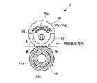
図6(a)において、定着ユニット9は、定着ベルト91の外周に対向する電磁加熱装置98を有し、定着ベルト91と電磁加熱装置98の間に磁束遮蔽板97を配置している。この場合、電磁加熱装置98の電磁誘導作用により、芯金および弾性層の外周に設けられた定着ベルト91の表面に形成された表面発熱層が加熱されることになる。
In FIG. 6A, the fixing
図6(b)に示すように、磁束遮蔽板97は、2枚の磁束遮蔽板97a、97bからなり、図示していない2本のレール(図3の95bに相当する)に案内されて定着ベルト91の軸方向(紙幅方向に相当する)に移動するようになっている。2枚の磁束遮蔽板97a、97bの駆動手段として、例えば、電磁コイル、プランジャ等を有するソレノイド機構が2つ設けられている。2つのソレノイド機構の作動によって2枚の磁束遮蔽板97a、97bが離隔することにより、双方の間に開口部(図3の95cに相当する)が形成される。前記2本のレールの対向間隔は一定であるため、前記開口部の用紙搬送方向の大きさは一定である。一方、2枚の磁束遮蔽板97a、97bの移動量に応じて前記開口部の紙幅方向の大きさが変化する。
As shown in FIG. 6B, the magnetic
ここでは、前記開口部の紙幅方向の大きさが、転写紙が前記ニップ部Nを通るときの通紙幅より大きくなるようにしている。したがって、前記開口部を通して定着ベルト91の表面発熱層を加熱するとき、電磁加熱装置98の電磁誘導作用により加熱される加熱領域の紙幅方向の大きさも通紙幅より大きくなる。
Here, the size of the opening in the paper width direction is set to be larger than the paper passing width when the transfer paper passes through the nip portion N. Accordingly, when the surface heating layer of the fixing
本実施の形態によれば、ヒータからなる熱源93に代えて電磁加熱装置98を定着ベルト91の外部に設けることにより、転写紙pが接する定着ベルト91の表面を効率よく加熱することができる。
According to the present embodiment, by providing the
また、本実施の形態によれば、定着ベルト91の外部に電磁加熱装置98および磁束遮蔽板97を設けることにより、定着ベルト91の構成を簡素にすることができると共に、メンテナンスや部品交換の作業が容易になる。
Further, according to the present embodiment, by providing the
なお、本実施の形態に限らず、複数の支持部材に張架された定着ベルト91を用いる構成であってもよい。また、定着ベルト91の内部に電磁加熱装置98を配置し、定着ベルト91の内周面に発熱層を形成し、内周面の発熱層と電磁加熱装置98の励磁コイルとの間に磁束遮蔽板97を配置してもよい。
Note that the present invention is not limited to this embodiment, and a configuration using a fixing
[第3の実施の形態]
図7〜図9に本発明の第3の実施の形態としての定着ユニットの要部構成を示す。これは、第1の実施の形態とは遮蔽板95の形状が相違している。なお、図7は本発明の第3の実施の形態としての定着ユニットの径方向の断面図である。図8は本発明の第3の実施の形態としての定着ユニットの平断面図および側断面図である。図9は本発明の第3の実施の形態としての遮蔽板の巻取繰出機構の説明図である。以下、第1の実施の形態と同一構成には同一名称を付与して説明を一部省略する。
[Third Embodiment]
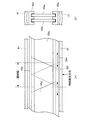
7 to 9 show the main configuration of a fixing unit according to the third embodiment of the present invention. This is different from the first embodiment in the shape of the shielding plate 95. FIG. 7 is a radial sectional view of a fixing unit according to a third embodiment of the present invention. FIG. 8 is a plan sectional view and a side sectional view of a fixing unit according to a third embodiment of the present invention. FIG. 9 is an explanatory diagram of a shield take-up / feeding mechanism as a third embodiment of the present invention. Hereinafter, the same components as those in the first embodiment are given the same names, and a part of the description is omitted.
図7において、定着ベルト91は、金属ベルトあるいは樹脂材料を用いて形成されている。定着ベルト91の表層には離型層が形成され、転写紙上の未定着トナーが付着しないようになっている。加圧ローラ94は、金属ローラ94aの外周に弾性層94bを設けた構成を有し、スプリング等によって定着ベルト91に押し付けられ、弾性層94bが押し潰されて、定着ベルト91との接触部が平坦なニップ部Nを形成している。
In FIG. 7, the fixing
定着ベルト91内には、平板状に形成された2枚の遮蔽板95d1、95d2を有し、双方が紙幅方向に平行移動可能となっている。また、2枚の遮蔽板95d1、95d2とも、一面(図中、下面)が熱源93に対向し、他の一面(図中、上面)が定着ベルト91の内周(図中、上部)に対向している。2枚の遮蔽板95d1、95d2が反対方向に移動して離隔することにより、双方の間に定着ベルト91の加熱領域に対応する開口部95f(図8(a)参照)が形成される。
The fixing
図8(a)に示すように、2本のレール95eは紙幅方向に平行であり、2枚の遮蔽板95d1、95d2の端辺は用紙搬送方向(図中、上下方向)に対して斜行している。したがって、遮蔽板95d1、95d2が離隔して形成される開口部95fは略台形となる。一方、開口部95fを閉塞する場合、2枚の遮蔽板95d1、95d2の一部が重なり合うことになる。双方が重なり合うのは、図中、点線で囲まれた三角形の領域である。また、2本のレール95eの対向間隔は一定であるため、開口部95fの用紙搬送方向の大きさ(前記台形の高さに相当する)は一定である。対して、2枚の遮蔽板95d1、95d2の移動量に応じて開口部95fの紙幅方向の大きさ(前記台形の上下辺の長さに相当する)が変化する。
As shown in FIG. 8A, the two
図8(b)に示すように、2本のレール95eには図中、上下1組のレール溝が都合2組並行して形成されている。この場合、遮蔽板95d1、95d2がそれぞれ異なる組のレール溝に沿って紙幅方向に移動することにより、斜行している前記端辺を重ね合わせて開口を閉塞することができる。
As shown in FIG. 8B, the two
図9に示すように、遮蔽板95d1、95d2はそれぞれ長尺フィルム状に形成され、2本のレール95eに沿いながら巻取繰出機構96によって巻取り繰出し自在となっている。詳細に図示していないが、巻取繰出機構96は、長尺フィルム状に形成された遮蔽板95dを装着するための巻取繰出ローラと、巻取繰出ローラを駆動(正転、逆転)する駆動手段としての巻取繰出モータと、巻取繰出モータの駆動力を巻取繰出ローラの回転軸に伝達する駆動伝達手段としてのプーリ、ギヤ等と、を有する。巻取繰出モータは、前述のソレノイド機構と同様にコントローラ300およびCPU307によって駆動制御される。
As shown in FIG. 9, the shielding plates 95d 1 and 95d 2 are each formed in a long film shape, and can be wound and fed by a winding and
ここで開口部95fを拡げる場合は、例えば、巻取繰出モータを正転させて遮蔽板95d1、95d2を形成する2巻の長尺フィルムを巻取り、開口部95fを縮める場合には、巻取繰出モータを逆転させて遮蔽板95d1、95d2を形成する2巻の長尺フィルムを繰出すようにしている。なお、開口部95fを閉じる場合には、前記三角形の領域が形成されるまで長尺フィルムを繰出すことになる。
Here, when the
本実施の形態では、前述のように開口部95fの形状を略台形とし、台形の平行な上下辺のうち長辺の長さが、通紙幅より長く(大きく)なるようにしている。したがって、開口部95fを通して熱源93の輻射熱を定着ベルト91の内周に供給するとき、輻射熱によって加熱される加熱領域の紙幅方向の大きさも通紙幅より大きくなる。前記加熱領域は、定着ベルト91の回動に伴って紙幅方向と垂直な方向に拡大することになる。よって、特に小サイズの転写紙に対する定着時、通紙領域に万遍なく必要十分な熱を供給することができる。
In the present embodiment, the shape of the
また、本実施の形態では、遮蔽板95d1、95d2の移動のための駆動手段としておよび巻取繰出機構96および巻取繰出モータを用いているので、遮蔽板95d1、95d2の間の開口部95fの大きさを無段階に調整することができる。
Further, in the present embodiment, the drive means for moving the shielding plates 95d 1 and 95d 2 and the winding /
[第4の実施の形態]
図10、図11に本発明の第4の実施の形態としての定着ユニットの要部構成を示す。これは、第1の実施の形態とは遮蔽板95gに矩形の開口部を有する点が相違している。なお、図10は本発明の第4の実施の形態としての定着ユニットの径方向の断面図である。図11は本発明の第4の実施の形態としての遮蔽板の平断面図および側断面図である。以下、第1の実施の形態と同一構成には同一名称を付与して説明を一部省略する。
[Fourth Embodiment]
FIG. 10 and FIG. 11 show the main configuration of a fixing unit as a fourth embodiment of the present invention. This is different from the first embodiment in that the shielding plate 95g has a rectangular opening. FIG. 10 is a sectional view in the radial direction of a fixing unit as a fourth embodiment of the present invention. FIG. 11 is a plan sectional view and a side sectional view of a shielding plate as a fourth embodiment of the present invention. Hereinafter, the same components as those in the first embodiment are given the same names, and a part of the description is omitted.
図10において、定着ベルト91は、金属ベルトあるいは樹脂材料を用いて形成されている。定着ベルト91の表層には離型層が形成され、転写紙上の未定着トナーが付着しないようになっている。加圧ローラ94は、金属ローラ94aの外周に弾性層94bを設けた構成を有している。また、加圧ローラ94は、スプリング等によって定着ベルト91に押し付けられ、弾性層94bが押し潰されて、定着ベルト91との接触部が平坦なニップ部Nを形成している。
In FIG. 10, the fixing
定着ベルト91内には、定着ベルト91の周方向に曲成された3枚の遮蔽板95g1、95g2、95g3を有する。遮蔽板95g1は固設され、一面(図中、上面)が定着ベルト91の内周に対向し、他の一面(図中、下面)が2枚の遮蔽板95g2、95g3に対向している。2枚の遮蔽板95g2、95g3は図示していない2本のレール(図3の95bに相当する)によって紙幅方向に移動可能となっており、双方とも一面(図中、上面)が遮蔽板95g1に対向し、他の一面(図中、下面)が熱源93および熱伝導体92に対向している。
The fixing
3枚の遮蔽板95g1、95g2、95g3には、紙幅方向に複数の同一矩形(ここでは、長方形)の開口部95h1、95h2、95h3が同一間隔をもって形成されている(図11参照)。遮蔽板95g1の開口部95h1と遮蔽板95g2、95g3の開口部95h2、95h3のいずれかが重なることにより(開口の一部が重なる場合を含む)、熱源93の輻射熱を定着ベルト91の加熱領域に供給するための開口部の面積および位置が段階的に変化するようになっている。
In the three shielding plates 95g 1 , 95g 2 , and 95g 3 , a plurality of openings 95h 1 , 95h 2 , and 95h 3 having the same rectangle (here, rectangular) are formed at the same interval in the paper width direction (see FIG. 11). The radiant heat of the
図11(a)に示すように、遮蔽板95g1の中央を除く4つの開口部95h1と遮蔽板95g2、95g3のそれぞれ2つの開口部95h2、95h3が重なる場合、遮蔽板95g1の中央の開口部95h1、遮蔽板95g1の中央を除く4つの開口部95h1、および遮蔽板95g2、95g3のそれぞれ2つの開口部95h2、95h3を通して、定着ベルト91の加熱領域に熱源93の輻射熱が供給される。前記加熱領域は大サイズ(例えば最大サイズ)の転写紙に対応する。この場合、定着ベルト91の紙幅方向の温度は略均一となる。
As shown in FIG. 11 (a), each of the two openings 95h 2 of the shielding plate 95g 2, 95g 3 and four openings 95h 1 except a central shielding plate 95g 1, if the 95h 3 overlap, the shielding plate 95g central opening 95h 1 of 1, through the shielding plate 95 g 4 one aperture 95h 1 except the center 1, and the shielding plate 95 g 2, each of the two openings 95h 2 of 95 g 3, 95h 3, the heating of the fixing
図11(b)に示すように、遮蔽板95g1の中央の開口部95h1の紙幅方向の大きさは、通紙幅より大きい。遮蔽板95g1の中央を除く4つの開口部95h1と遮蔽板95g2、95g3のそれぞれ2つの開口部95h2、95h3がいずれも重ならない場合、遮蔽板95g1の中央の開口部95h1を通して、定着ベルト91の加熱領域に熱源93の輻射熱が供給される。前記加熱領域は小サイズ(例えば最小サイズ)の転写紙に対応する。この場合、熱源93の輻射熱は定着ベルト91の非加熱領域に供給されない。
As shown in FIG. 11 (b), the sheet width direction of the size of the central opening 95h 1 of the shielding plate 95 g 1 is greater than the sheet passing width. When the shielding plate 95 g 4 one aperture 95h 1 except the center 1 and the shielding plate 95 g 2, each of the two openings of 95 g 3 95h 2, 95h 3 does not overlap any, central opening 95h of the shielding plate 95 g 1 1 , the radiant heat of the
なお、図11(a)、(b)のいずれも、熱源93の輻射熱の一部は、3枚の遮蔽板95g1、95g2、95g3の下面(非開口部)に形成された光沢面によって反射され、熱伝導体92に供給されることになる。
11A and 11B, a part of the radiant heat of the
本実施の形態によれば、遮蔽板95g2、95g3の紙幅方向への移動によって開口部95h1、95h2、95h3のいずれかが重なることにより、熱源93の輻射熱を定着ベルト91の加熱領域に供給するための開口部の面積および位置を段階的に変更することができる。よって、転写紙の紙幅に応じて定着ベルト91および加熱ローラ94に熱エネルギーを効率的に供給することができる。また、不要なエネルギー消費を抑制することができる。
According to the present embodiment, any one of the openings 95h 1 , 95h 2 , and 95h 3 is overlapped by the movement of the shielding plates 95g 2 and 95g 3 in the paper width direction, whereby the radiant heat of the
また、本実施の形態によれば、遮蔽板95g1の中央の開口部95h1の紙幅方向の大きさを通紙幅より大きくすることにより、小サイズの転写紙に対する定着時、通紙領域に万遍なく必要十分な熱を供給することができる。 Further, according to this embodiment, by greater than sheet width the width direction of the size of the central opening 95h 1 of the shielding plate 95 g 1, when fixing with respect to the transfer paper of a small size, the sheet passing area ten thousand Uniformly necessary and sufficient heat can be supplied.
[第5の実施の形態]
図12に本発明の第5の実施の形態としての遮蔽板の構成を示す。これは、第1の実施の形態とは遮蔽板95に平行四辺形の開口部を有する点が相違している。以下、第1の実施の形態と同一構成には同一名称を付与して説明を一部省略する。
[Fifth Embodiment]
FIG. 12 shows a configuration of a shielding plate as a fifth embodiment of the present invention. This is different from the first embodiment in that the shielding plate 95 has a parallelogram opening. Hereinafter, the same components as those in the first embodiment are given the same names, and a part of the description is omitted.
本実施の形態において、定着ベルト91内には、定着ベルト91の周方向に曲成された3枚の遮蔽板95i1、95i2、95i3を有する。遮蔽板95i1は固設され、一面(図中、上面)が定着ベルト91の内周に対向し、他の一面(図中、下面)が2枚の遮蔽板95i2、95i3に対向している。2枚の遮蔽板95i2、95i3は図示していない2本のレール(図3の95bに相当する)によって紙幅方向に移動可能となっている。遮蔽板95i2、95i3とも一面(図中、上面)が遮蔽板95i1に対向し、他の一面(図中、下面)が熱源93および熱伝導体92に対向している。
In the present embodiment, the fixing
3枚の遮蔽板95i1、95i2、95i3には、紙幅方向に複数の同一平行四辺形の開口部95j1、95j2、95j3が同一間隔をもって形成されている(図12参照)。ここで、遮蔽板95i1の開口部95j1と遮蔽板95i2、95i3の開口部95j2、95j3のいずれかが重なることにより(開口の一部が重なる場合を含む)、熱源93の輻射熱を定着ベルト91の加熱領域に供給するための開口部が形成される。
The three shielding plates 95 i 1, the 95 i 2, 95 i 3, an
図12(a)に示すように、遮蔽板95i1の中央の2つを除く4つの開口部95j1と遮蔽板95i2、95i3のそれぞれ2つの開口部95j2、95j3が重なる場合、遮蔽板95i1の中央の2つの開口部95j1、遮蔽板95i1の中央の2つを除く4つの開口部95j1、および遮蔽板95i2、95i3のそれぞれ2つの開口部95j2、95j3を通して、定着ベルト91の加熱領域に熱源93の輻射熱が供給される。前記加熱領域は、大サイズ(例えば最大サイズ)の転写紙に対応する。
Figure 12 (a), the case where each of the two openings 95j 2, 95j 3 of the shielding plate 95 i 2, 95 i 3 and four openings 95j 1 except two of the center of the shielding plate 95 i 1 overlap, the shielding plate 95 i two openings 95j 1 of the central 1, the shielding plate 95 i 4 one aperture 95j 1 but two central 1, and the shielding plate 95 i 2, each of the two openings of 95 i 3 95j 2, 95j 3 , the radiant heat of the
図12(b)に示すように、遮蔽板95i1の中央の2つを除く4つの開口部95j1と遮蔽板95i2、95i3のそれぞれ2つの開口部95j2、95j3がいずれも重ならない場合、遮蔽板95i1の中央の2つの開口部95j1を通して、定着ベルト91の加熱領域に熱源93の輻射熱が供給される。前記加熱領域は、小サイズ(例えば最小サイズ)の転写紙に対応する。
As shown in FIG. 12 (b), heavy either each two openings 95j 2, 95j 3 of the shielding plate 95 i 2, 95 i 3 and four openings 95j 1 except two of the center of the shielding plate 95 i 1 If not, through two openings 95j 1 of the center of the shielding plate 95 i 1, the radiant heat of the
ここで、平行四辺形をなす開口部95j1、95j2、95j3の隣り合う間隔は、前記平行四辺形の平行な上下辺の長さと同一である。また、前記加熱領域は、定着ベルト91の回動に伴って紙幅方向と垂直な方向に拡大する。よって、開口部95jが前記間隔をもって形成されているにも関らず、定着ベルト91の加熱領域に万遍なく、熱源93の輻射熱が供給される。また、紙幅方向における開口端部が通紙幅を超過するよう、遮蔽板95i2、95i3を移動させることにより、開口部95jの紙幅方向の大きさが転写紙の紙幅より大きくなるようにしている。
Here, the adjacent intervals of the openings 95j 1 , 95j 2 , 95j 3 forming the parallelogram are the same as the lengths of the parallel upper and lower sides of the parallelogram. The heating area expands in a direction perpendicular to the paper width direction as the fixing
なお、いずれの場合も、熱源93の輻射熱の一部は、3枚の遮蔽板95i1、95i2、95i3の下面(非開口部)に形成された光沢面によって反射され、熱伝導体92に供給されることになる。
In any case, a part of the radiant heat of the
本実施の形態によれば、平行四辺形をなす開口部95j1、95j2、95j3の間隔を前記平行四辺形の平行な上下辺の長さと同一にしたことにより、定着時に開口部のピッチ状に温度むら(加熱むら)が生じるのを回避して、転写紙を均一に加熱することができる。 According to the present embodiment, the interval between the openings 95j 1 , 95j 2 , 95j 3 forming the parallelogram is the same as the length of the parallel upper and lower sides of the parallelogram, so that the pitch of the openings during fixing is fixed. It is possible to uniformly heat the transfer paper while avoiding temperature unevenness (heating unevenness).
また、本実施の形態によれば、紙幅方向における開口端部が通紙幅を超過するよう、遮蔽板95i2、95i3を移動させることにより、加熱領域の紙幅方向の大きさは通紙幅より大きくなる。よって、特に小サイズの転写紙に対する定着時、通紙領域に万遍なく必要十分な熱を供給することができる。 Further, according to the present embodiment, the size of the heating region in the paper width direction is larger than the paper passing width by moving the shielding plates 95i 2 and 95i 3 so that the opening end in the paper width direction exceeds the paper passing width. Become. Therefore, particularly when fixing to a small size transfer paper, necessary and sufficient heat can be uniformly supplied to the paper passing area.
なお、前述した各実施の形態では、定着部材、加圧部材として定着ベルト91、加圧ローラ94を用いた場合について説明したが、本発明はこのほかに、定着ローラ、加圧ベルトを用いても同様の効果が得られるものである。この場合、定着ローラとしては、例えば、アルミ系または鉄系の材料からなる芯金に、耐熱樹脂材料(例えば、フッ素樹脂)または耐熱ゴムを被覆したもの、あるいは耐熱ゴムを被覆し、さらに外側に耐熱樹脂(例えば、フッ素樹脂)を被覆したもの、を用いる。加圧ベルトとしては、例えば、耐熱ゴム材料、耐熱樹脂材料からなるもの、あるいは耐熱ゴム層と耐熱樹脂層とを積層したもの、を用いる。
In each of the above-described embodiments, the case where the fixing
また、前述した各実施の形態では、転写紙として大小2種類のサイズ(紙幅)を用いた場合について説明したが、本発明はこのほかに、中サイズの転写紙を加えても同様の効果が得られるものである。例えば、第4、第5の実施の形態においては、紙幅方向に移動可能な遮蔽板の組の種類を追加すると共に、定着対象以外の遮蔽板の組を退避させる退避部材(例えば、引込用レール)および駆動手段(例えば、ソレノイド)を増設してもよい。 In each of the above-described embodiments, the case where two types of sizes (paper widths) are used as transfer paper has been described. However, the present invention has the same effect even when medium-size transfer paper is added. It is obtained. For example, in the fourth and fifth embodiments, a type of a set of shielding plates that can move in the paper width direction is added, and a retracting member that retracts a set of shielding plates other than the fixing target (for example, a pull-in rail) ) And driving means (for example, a solenoid) may be added.
また、前述した第1、第2、第4、第5実施の形態では、遮蔽板または磁束遮蔽板の駆動手段としてソレノイド機構を用いた場合について説明したが、本発明はこのほかに、ラック・アンド・ピニオン機構および駆動モータを用いてもよい。例えば、遮蔽板または磁束遮蔽板にラックを設け、ラックと噛み合わせるピニオンを駆動モータの駆動で回転させる。この構成により、前述した2本のレールに沿って遮蔽板または磁束遮蔽板を紙幅方向に移動させることができる。よって、遮蔽板または磁束遮蔽板を紙幅方向に無段階に移動させることができる。 In the first, second, fourth, and fifth embodiments described above, the case where the solenoid mechanism is used as the driving means for the shielding plate or the magnetic flux shielding plate has been described. An and pinion mechanism and a drive motor may be used. For example, a rack is provided on the shielding plate or the magnetic flux shielding plate, and a pinion that meshes with the rack is rotated by driving of a drive motor. With this configuration, the shielding plate or the magnetic flux shielding plate can be moved in the paper width direction along the two rails described above. Therefore, the shielding plate or the magnetic flux shielding plate can be moved steplessly in the paper width direction.
最後に、各請求項の発明に相当する実施の形態の作用効果を述べる。 Finally, the operation and effect of the embodiment corresponding to the invention of each claim will be described.
(1)前述した第1から第5の実施の形態の定着ユニット9によれば、例えば、遮蔽板95aが定着ベルト91と熱源93との間を転写紙pの紙幅方向に移動して、開口部95cの大きさを変更することにより定着ベルト91の内周の加熱領域を変更するので、転写紙pの紙幅に応じて加熱領域を変更することができる。また、遮蔽板95aは転写紙pの紙幅方向に移動するので、転写紙搬送方向において開口部95cの大きさが制限されることはない。したがって、遮蔽板95aの移動によって定着処理に必要十分な熱を供給するように加熱領域を変更することができる。適切な加熱領域とすることよって定着ベルト91および熱伝導体92を効率的に加熱すると共に、定着ユニット9の径方向の大型化を抑制することができる。
(1) According to the fixing
なお、前述の各実施の形態において、例えば、コントローラ300は紙幅情報検知手段に相当する。例えば、定着ユニット9は定着装置に相当する。例えば、遮蔽板95a、レール95b、95e、巻取繰出機構96、磁束遮蔽板97は、加熱領域可変手段に相当する。例えば、定着ベルト91は定着部材に相当する。例えば、ヒータからなる熱源93、電磁加熱装置98は加熱手段に相当する。例えば、転写紙pは記録媒体に相当する。例えば、熱伝導体92は押圧部材に相当する。
In each of the above-described embodiments, for example, the
(2)前述した第1から第5の実施の形態の定着ユニット9によれば、例えば、定着ベルト91において開口部95cを通して転写紙pの紙幅よりも幅広の領域が加熱されるので、転写紙pの紙幅方向における通紙領域端部で転写紙pおよび定着ベルト91の非通紙領域により熱が奪われ、定着のための熱量が不足するのを防止することができる。
(2) According to the fixing
(3)前述した第1、第3〜第5の実施の形態の定着ユニット9によれば、例えば、熱源93が発する熱エネルギー(輻射熱)は、遮蔽板95aの開口部95cを通して定着ベルト91の加熱領域に供給される。また、前記輻射熱は、熱源93と対向する熱伝導体92に直接供給される。さらに、前記輻射熱は、遮蔽板95aに反射して熱伝導体92に間接供給される。熱源93の輻射熱を熱伝導体92に対して直接および間接に供給することにより、熱伝導体92に当接している定着ベルト91を効率よく加熱することができる。
(3) According to the fixing
(4)前述した第1、第3の実施の形態の定着ユニット9によれば、例えば、2枚の遮蔽板95a1、95a2が転写紙pの紙幅方向へ相対的に移動することにより、双方が離間して開口部95cが形成され、あるいは双方が接して開口が閉塞される。前述のように開口部95cの大きさを変更することによって、転写紙pの紙幅に応じて加熱領域を調整することができる。
(4) According to the fixing
なお、前述の各実施の形態において、例えば、遮蔽板95a1、95a2、95d1、95d2は複数の板状部材に相当する。例えば、前記ソレノイド機構、巻取繰出機構96は移動手段に相当する。例えば、開口部95c、95fは開口部に相当する。
In each of the above-described embodiments, for example, the
(5)前述した第4、第5の実施の形態の定着ユニット9によれば、例えば、遮蔽板95g1と遮蔽板95g2、95g3とが転写紙pの紙幅方向へ相対的に移動することにより、開口部95h1と開口部95h2、95h3とが重複して開口し(重複開口領域が形成され)、あるいは開口が閉塞される。前述のように重複開口領域を変位することによって、転写紙pの紙幅に応じて加熱領域を調整することができる。また、開口部を有する遮蔽板95g1と開口部を有する遮蔽板95g2、95g3とを重ねて重複開口領域を変位するようにしているので、例えば、紙幅方向に連なる2つの板状部材の端部間隔を可変する場合に比べ、加熱領域可変手段としての遮蔽板95g1、遮蔽板95g2、95g3および前記レールの長尺化を抑制することができる。よって、定着ユニット9の大型化を抑制することができる。
(5) Fourth described above, according to the fixing
なお、前述の各実施の形態において、例えば、遮蔽板95g1、95g2、95g3、95i1、95i2、95i3は複数の板状部材に相当する。例えば、開口部95h1、95h2、95h3、95j1、95j2、95j3は開口部に相当する。例えば、図11(a)の遮蔽板95g1の左端の開口部95h1と遮蔽板95g2の左端の開口部95h2とは重複開口領域に相当する。
In each of the above-described embodiments, for example, the shielding plates 95g 1 , 95g 2 , 95g 3 , 95i 1 , 95i 2 , and 95i 3 correspond to a plurality of plate-like members. For example, the openings 95h 1, 95h 2, 95h 3 ,
(6)前述した第1〜第5の実施の形態の複写機202によれば、例えば、転写紙pにトナー画像を形成するためのエンジン305と、未定着トナー画像を転写紙pに定着するための(1)から(5)のいずれかに記載の定着ユニット9と、設けることにより、前述した定着ユニット9の作用で転写紙pの紙幅に対応しながら定着処理に要するエネルギー消費を抑制することができる。また、定着ユニット9ばかりでなく、複写機202の大型化をも抑制することができる。
(6) According to the copying
なお、前述の各実施の形態において、例えば、エンジン制御ボード304、エンジン305は画像形成手段に相当する。例えば、複写機202は画像形成装置に相当する。
In each of the above-described embodiments, for example, the
1Y 感光体ドラム
1M 感光体ドラム
1C 感光体ドラム
1K 感光体ドラム
2Y 帯電装置
2M 帯電装置
2C 帯電装置
2K 帯電装置
3 書込みユニット
3Y レーザ装置
3M レーザ装置
3C レーザ装置
3K レーザ装置
4Y 現像装置
4M 現像装置
4C 現像装置
4K 現像装置
6 転写ベルト
7A 転写ローラ
7Y 転写ローラ
7M 転写ローラ
7C 転写ローラ
7K 転写ローラ
8A クリーニング装置
8Y クリーニング装置
8M クリーニング装置
8C クリーニング装置
8K クリーニング装置
9 定着ユニット
12 原稿テーブル
15、107 インタフェース
16 ホスト(ホストコンピュータ)
17 シーケンス機器群
20 給紙カセット
21 給紙ベルト
22 給紙ローラ
23 レジストローラ
24 排紙ローラ
25 操作パネル
28、29 原稿排紙トレイ
30、31 原稿長さセンサ
39 給紙ベルト
40 分離ローラ
41 反転ローラ
42 スリットガラス
43 コンタクトガラス
53、54 センサ群
60 入出力インタフェース(I/O)
91 定着ベルト
92 熱伝導体(押圧部材)
93 熱源
94 加圧ローラ
95a(95a1、95a2)、95d(95d1、95d2)、95g(95g1、95g2、95g3)、95i(95i1、95i2、95i3) 遮蔽板
95b、95e レール
95c、95f、95h(95h1、95h2、95h3)、95j(95j1、95j2、95j3) 開口部
96 巻取繰出機構
97(97a、97b) 磁束遮蔽板
98 電磁加熱装置(HI装置)
101 ADFコントローラ
120 駆動部
201 ADF
202 複写機
300 コントローラ
301 画像読取部(スキャナユニット)
302 画像形成部
303 給紙部
304 エンジン制御ボード
305 エンジン
307 CPU
308 RAM
309 ROM
310 EEPROM
311 切替スイッチ(DIP/SW)
1Y
17
91
93 the
101
202
302
308 RAM
309 ROM
310 EEPROM
311 changeover switch (DIP / SW)
Claims (6)
通紙される記録媒体の紙幅情報を検知する紙幅情報検知手段と、前記加熱手段により加熱される定着部材の加熱領域を、前記紙幅情報検知手段が検知した情報に基づいて可変する加熱領域可変手段と、を備え、
前記加熱領域可変手段が、前記定着部材と前記加熱手段との間を紙幅方向に移動して加熱領域を可変することを特徴とする定着装置。 A fixing member; a pressure member that forms a nip portion facing the fixing member; and a heating unit that heats the fixing member in a non-contact state with the surface of the fixing member, and passes through the nip portion. In a fixing device for fixing an unfixed toner image on a recording medium to be
Paper width information detecting means for detecting the paper width information of the recording medium to be passed, and heating area variable means for changing the heating area of the fixing member heated by the heating means based on the information detected by the paper width information detecting means And comprising
The fixing device according to claim 1, wherein the heating area changing means changes the heating area by moving in a paper width direction between the fixing member and the heating means.
前記定着手段として請求項1から請求項5のいずれか一項に記載の定着装置を用いることを特徴とする画像形成装置。 Image forming means for forming a toner image on the recording medium; and fixing means for fixing an unfixed toner image formed by the image forming means to the recording medium,
An image forming apparatus using the fixing device according to claim 1 as the fixing unit.
Priority Applications (3)
| Application Number | Priority Date | Filing Date | Title |
|---|---|---|---|
| JP2008233550A JP5239662B2 (en) | 2008-09-11 | 2008-09-11 | Fixing apparatus and image forming apparatus |
| CN2009101687068A CN101673078B (en) | 2008-09-11 | 2009-09-03 | Fixing unit and image forming apparatus using same |
| US12/585,231 US8351807B2 (en) | 2008-09-11 | 2009-09-09 | Fixing unit including heating area adjustor and image forming apparatus using same |
Applications Claiming Priority (1)
| Application Number | Priority Date | Filing Date | Title |
|---|---|---|---|
| JP2008233550A JP5239662B2 (en) | 2008-09-11 | 2008-09-11 | Fixing apparatus and image forming apparatus |
Publications (2)
| Publication Number | Publication Date |
|---|---|
| JP2010066583A true JP2010066583A (en) | 2010-03-25 |
| JP5239662B2 JP5239662B2 (en) | 2013-07-17 |
Family
ID=42007331
Family Applications (1)
| Application Number | Title | Priority Date | Filing Date |
|---|---|---|---|
| JP2008233550A Active JP5239662B2 (en) | 2008-09-11 | 2008-09-11 | Fixing apparatus and image forming apparatus |
Country Status (3)
| Country | Link |
|---|---|
| US (1) | US8351807B2 (en) |
| JP (1) | JP5239662B2 (en) |
| CN (1) | CN101673078B (en) |
Cited By (31)
| Publication number | Priority date | Publication date | Assignee | Title |
|---|---|---|---|---|
| JP2012063463A (en) * | 2010-09-14 | 2012-03-29 | Ricoh Co Ltd | Fixing device and image forming apparatus |
| JP2012128312A (en) * | 2010-12-17 | 2012-07-05 | Canon Inc | Image heating device |
| JP2013105082A (en) * | 2011-11-15 | 2013-05-30 | Canon Inc | Image heating device |
| JP2013164430A (en) * | 2012-01-13 | 2013-08-22 | Ricoh Co Ltd | Fixing device and image forming apparatus |
| JP2013174785A (en) * | 2012-02-27 | 2013-09-05 | Ricoh Co Ltd | Fixing device and image forming apparatus |
| JP2013195555A (en) * | 2012-03-16 | 2013-09-30 | Ricoh Co Ltd | Fixing device, image forming device, and heat quantity adjustment method |
| JP2013200582A (en) * | 2013-07-10 | 2013-10-03 | Canon Inc | Image heating device |
| JP2014029374A (en) * | 2012-07-31 | 2014-02-13 | Canon Inc | Image heating device |
| KR20140031118A (en) * | 2012-09-04 | 2014-03-12 | 캐논 가부시끼가이샤 | Fixing apparatus and image forming apparatus |
| JP2014074884A (en) * | 2012-09-14 | 2014-04-24 | Ricoh Co Ltd | Fixing device and image forming apparatus |
| JP2014174440A (en) * | 2013-03-12 | 2014-09-22 | Ricoh Co Ltd | Fixing device and image forming apparatus |
| JP2014222316A (en) * | 2013-05-14 | 2014-11-27 | 株式会社リコー | Fixing device and image forming apparatus |
| JP2014224839A (en) * | 2013-05-15 | 2014-12-04 | 株式会社リコー | Fixing device and image forming apparatus including the same |
| JP2014232269A (en) * | 2013-05-30 | 2014-12-11 | 株式会社リコー | Fixing apparatus and image forming apparatus |
| US9026024B2 (en) | 2012-02-09 | 2015-05-05 | Ricoh Company, Ltd. | Fixing device capable of minimizing damage of endless rotary body and image forming apparatus incorporating same |
| US9031439B2 (en) | 2012-01-31 | 2015-05-12 | Ricoh Company, Limited | Fixing device and image forming device |
| US9046833B2 (en) | 2012-09-14 | 2015-06-02 | Ricoh Company, Ltd. | Fixing device and image forming apparatus incorporating same |
| US9046838B2 (en) | 2012-09-14 | 2015-06-02 | Ricoh Company, Ltd. | Fixing device and image forming apparatus |
| JP2015118238A (en) * | 2013-12-18 | 2015-06-25 | コニカミノルタ株式会社 | Fixing apparatus and image forming apparatus |
| JP2015132859A (en) * | 2012-09-14 | 2015-07-23 | 株式会社リコー | Fixing device and image forming apparatus |
| JP2015146057A (en) * | 2012-01-13 | 2015-08-13 | 株式会社リコー | Fixing device and image forming apparatus |
| US9164443B2 (en) | 2013-05-29 | 2015-10-20 | Ricoh Company, Ltd. | Fixing device and image forming apparatus |
| US9229379B2 (en) | 2012-09-11 | 2016-01-05 | Ricoh Company, Limited | Fixing device and image forming apparatus |
| US9285728B2 (en) | 2013-03-15 | 2016-03-15 | Ricoh Company, Ltd. | Image forming apparatus including a heat shield interposed between a heater and a fixing rotary body and image forming method |
| JP2016048332A (en) * | 2014-08-28 | 2016-04-07 | 京セラドキュメントソリューションズ株式会社 | Fixation device and image forming apparatus |
| US9348272B2 (en) | 2013-03-15 | 2016-05-24 | Ricoh Company, Ltd. | Fixing device including a reinforced heat shield and image forming apparatus |
| US9389550B2 (en) | 2013-03-15 | 2016-07-12 | Ricoh Company, Ltd. | Fixing device, image forming apparatus, and fixing method |
| JP2016170449A (en) * | 2016-06-30 | 2016-09-23 | 株式会社リコー | Fixing device and image forming apparatus |
| US9535380B2 (en) | 2013-05-29 | 2017-01-03 | Ricoh Company, Ltd. | Fixing device and image forming apparatus |
| US9709929B2 (en) | 2015-12-16 | 2017-07-18 | S-Printing Solution Co., Ltd. | Fixing device and image forming apparatus including the same |
| JP2017142541A (en) * | 2012-09-14 | 2017-08-17 | 株式会社リコー | Fixing device and image forming apparatus |
Families Citing this family (20)
| Publication number | Priority date | Publication date | Assignee | Title |
|---|---|---|---|---|
| JP5175648B2 (en) | 2008-07-30 | 2013-04-03 | 京セラドキュメントソリューションズ株式会社 | Image forming apparatus |
| JP2011175223A (en) * | 2010-01-29 | 2011-09-08 | Ricoh Co Ltd | Fixing device and image forming apparatus |
| US9152106B2 (en) | 2012-08-31 | 2015-10-06 | Ricoh Company, Ltd. | Fixing device and image forming apparatus including same |
| JP2014067009A (en) * | 2012-09-06 | 2014-04-17 | Canon Inc | Image forming apparatus, and control method of image forming apparatus |
| JP6236815B2 (en) * | 2013-03-15 | 2017-11-29 | 株式会社リコー | Fixing apparatus and image forming apparatus |
| JP6176437B2 (en) | 2013-03-15 | 2017-08-09 | 株式会社リコー | Fixing apparatus and image forming apparatus |
| JP2014199417A (en) | 2013-03-15 | 2014-10-23 | 株式会社リコー | Fixing device and image forming apparatus |
| JP6221546B2 (en) * | 2013-05-14 | 2017-11-01 | 株式会社リコー | Fixing apparatus and image forming apparatus |
| JP6160227B2 (en) * | 2013-05-16 | 2017-07-12 | 株式会社リコー | Fixing device and image forming apparatus having the same |
| JP2014235308A (en) * | 2013-05-31 | 2014-12-15 | 株式会社リコー | Fixing device and image forming apparatus |
| JP6093723B2 (en) * | 2014-02-28 | 2017-03-08 | 京セラドキュメントソリューションズ株式会社 | Fixing apparatus and image forming apparatus |
| JP6321507B2 (en) * | 2014-09-24 | 2018-05-09 | 東芝テック株式会社 | Fixing apparatus and image forming apparatus |
| JP6237577B2 (en) * | 2014-11-10 | 2017-11-29 | 京セラドキュメントソリューションズ株式会社 | Fixing apparatus and image forming apparatus |
| JP2016110014A (en) * | 2014-12-10 | 2016-06-20 | キヤノン株式会社 | Fixation device and image formation device |
| US9874839B2 (en) | 2015-06-23 | 2018-01-23 | Ricoh Company, Ltd. | Fixing device and image forming apparatus |
| JP6583716B2 (en) | 2015-07-07 | 2019-10-02 | 株式会社リコー | Fixing apparatus and image forming apparatus |
| CN110275411A (en) * | 2018-03-15 | 2019-09-24 | 柯尼卡美能达办公系统研发(无锡)有限公司 | Fixing device and image forming apparatus |
| US20190286024A1 (en) * | 2018-03-16 | 2019-09-19 | Kabushiki Kaisha Toshiba | Image forming apparatus and fixing method |
| KR20200107383A (en) * | 2019-03-07 | 2020-09-16 | 휴렛-팩커드 디벨롭먼트 컴퍼니, 엘.피. | Developing cartridge having a heat transfer blocking member |
| KR20200112118A (en) * | 2019-03-21 | 2020-10-05 | 휴렛-팩커드 디벨롭먼트 컴퍼니, 엘.피. | Scanner capable of flatbed type scanning with image reading unit disposed in upper unit |
Citations (6)
| Publication number | Priority date | Publication date | Assignee | Title |
|---|---|---|---|---|
| JPS6478274A (en) * | 1987-09-21 | 1989-03-23 | Minolta Camera Kk | Image recorder |
| JPH0281552U (en) * | 1988-12-12 | 1990-06-22 | ||
| JPH07230227A (en) * | 1994-02-17 | 1995-08-29 | Ricoh Co Ltd | Image forming device |
| JP2001215829A (en) * | 2000-02-07 | 2001-08-10 | Konica Corp | Fixing device |
| JP2002040850A (en) * | 2000-07-31 | 2002-02-06 | Konica Corp | Fixing device |
| JP2005338724A (en) * | 2004-05-31 | 2005-12-08 | Fuji Xerox Co Ltd | Fixing device and image forming apparatus |
Family Cites Families (28)
| Publication number | Priority date | Publication date | Assignee | Title |
|---|---|---|---|---|
| JPH07287460A (en) | 1994-04-18 | 1995-10-31 | Ricoh Co Ltd | Fixing device |
| JP3410845B2 (en) * | 1995-01-24 | 2003-05-26 | 株式会社リコー | Fixing device |
| JP3392570B2 (en) * | 1995-03-14 | 2003-03-31 | 株式会社リコー | Fixing device |
| DE19650283C2 (en) * | 1995-12-05 | 2001-09-20 | Ricoh Kk | Heating roller fixing device |
| US5970298A (en) * | 1997-04-28 | 1999-10-19 | Ricoh Company, Ltd. | Fixing method and device with a controllable web system and image forming apparatus incorporating the method device and system |
| US6305636B1 (en) * | 1998-10-23 | 2001-10-23 | Ricoh Company, Ltd. | Web driving device |
| JP2001209266A (en) | 2000-01-28 | 2001-08-03 | Ricoh Co Ltd | Fixing device |
| JP2002132080A (en) | 2000-10-30 | 2002-05-09 | Fuji Xerox Co Ltd | Fixing device |
| JP2003098719A (en) * | 2001-09-21 | 2003-04-04 | Ricoh Co Ltd | Developer, fixing device and image forming apparatus |
| JP4176461B2 (en) | 2002-12-26 | 2008-11-05 | 株式会社リコー | Belt fixing device |
| JP3929942B2 (en) | 2003-06-26 | 2007-06-13 | 株式会社リコー | Fixing apparatus and image forming apparatus |
| WO2005038533A1 (en) * | 2003-10-17 | 2005-04-28 | Matsushita Electric Industrial Co., Ltd. | Fixing device |
| JP2005189268A (en) | 2003-12-24 | 2005-07-14 | Ricoh Co Ltd | Fixing device and image forming apparatus with the device |
| JP2004145368A (en) | 2004-01-27 | 2004-05-20 | Fuji Xerox Co Ltd | Fixing device |
| JP4353419B2 (en) * | 2004-02-12 | 2009-10-28 | 株式会社リコー | Fixing apparatus and image forming apparatus |
| CN100444048C (en) * | 2004-10-22 | 2008-12-17 | 佳能株式会社 | Image heating apparatus |
| JP4654704B2 (en) | 2005-02-10 | 2011-03-23 | 富士ゼロックス株式会社 | Fixing apparatus and image forming apparatus |
| JP2006243497A (en) | 2005-03-04 | 2006-09-14 | Fuji Xerox Co Ltd | Fixing device |
| JP2006251479A (en) | 2005-03-11 | 2006-09-21 | Fuji Xerox Co Ltd | Fixing device and image forming device |
| JP2006267420A (en) | 2005-03-23 | 2006-10-05 | Fuji Xerox Co Ltd | Fixing device |
| JP4821265B2 (en) | 2005-10-25 | 2011-11-24 | 富士ゼロックス株式会社 | Fixing apparatus and image forming apparatus |
| JP2007163794A (en) | 2005-12-13 | 2007-06-28 | Fuji Xerox Co Ltd | Fixing device and image forming apparatus |
| JP5114843B2 (en) | 2005-12-22 | 2013-01-09 | 富士ゼロックス株式会社 | Endless belt used for fixing device, fixing device using endless belt, and image forming apparatus |
| JP5092239B2 (en) | 2005-12-26 | 2012-12-05 | 富士ゼロックス株式会社 | Fixing apparatus and image forming apparatus |
| JP4936430B2 (en) * | 2006-05-29 | 2012-05-23 | 株式会社リコー | Fixing apparatus and image forming apparatus |
| JP4818826B2 (en) | 2006-06-19 | 2011-11-16 | 株式会社リコー | Fixing apparatus and image forming apparatus |
| JP2007058249A (en) | 2006-12-04 | 2007-03-08 | Ricoh Co Ltd | Fixing device |
| JP5091725B2 (en) * | 2008-03-07 | 2012-12-05 | 京セラドキュメントソリューションズ株式会社 | Image forming apparatus |
-
2008
- 2008-09-11 JP JP2008233550A patent/JP5239662B2/en active Active
-
2009
- 2009-09-03 CN CN2009101687068A patent/CN101673078B/en not_active Expired - Fee Related
- 2009-09-09 US US12/585,231 patent/US8351807B2/en active Active
Patent Citations (6)
| Publication number | Priority date | Publication date | Assignee | Title |
|---|---|---|---|---|
| JPS6478274A (en) * | 1987-09-21 | 1989-03-23 | Minolta Camera Kk | Image recorder |
| JPH0281552U (en) * | 1988-12-12 | 1990-06-22 | ||
| JPH07230227A (en) * | 1994-02-17 | 1995-08-29 | Ricoh Co Ltd | Image forming device |
| JP2001215829A (en) * | 2000-02-07 | 2001-08-10 | Konica Corp | Fixing device |
| JP2002040850A (en) * | 2000-07-31 | 2002-02-06 | Konica Corp | Fixing device |
| JP2005338724A (en) * | 2004-05-31 | 2005-12-08 | Fuji Xerox Co Ltd | Fixing device and image forming apparatus |
Cited By (45)
| Publication number | Priority date | Publication date | Assignee | Title |
|---|---|---|---|---|
| JP2012063463A (en) * | 2010-09-14 | 2012-03-29 | Ricoh Co Ltd | Fixing device and image forming apparatus |
| JP2012128312A (en) * | 2010-12-17 | 2012-07-05 | Canon Inc | Image heating device |
| JP2013105082A (en) * | 2011-11-15 | 2013-05-30 | Canon Inc | Image heating device |
| US9042799B2 (en) | 2012-01-13 | 2015-05-26 | Ricoh Company, Ltd. | Fixing device and image forming apparatus |
| JP2013164430A (en) * | 2012-01-13 | 2013-08-22 | Ricoh Co Ltd | Fixing device and image forming apparatus |
| US11353812B2 (en) | 2012-01-13 | 2022-06-07 | Ricoh Company, Ltd. | Fixing device and image forming apparatus |
| US11003119B2 (en) | 2012-01-13 | 2021-05-11 | Ricoh Company, Ltd. | Fixing device and image forming apparatus |
| US10551777B2 (en) | 2012-01-13 | 2020-02-04 | Ricoh Company, Ltd. | Fixing device and image forming apparatus |
| US10209654B2 (en) | 2012-01-13 | 2019-02-19 | Ricoh Company, Ltd. | Fixing device and image forming apparatus |
| US9715198B2 (en) | 2012-01-13 | 2017-07-25 | Ricoh Company, Ltd. | Fixing device and image forming apparatus |
| US9285724B2 (en) | 2012-01-13 | 2016-03-15 | Ricoh Company, Ltd. | Fixing device and image forming apparatus |
| JP2015146057A (en) * | 2012-01-13 | 2015-08-13 | 株式会社リコー | Fixing device and image forming apparatus |
| US9405242B2 (en) | 2012-01-31 | 2016-08-02 | Ricoh Company, Ltd. | Fixing device and image forming device |
| US9031439B2 (en) | 2012-01-31 | 2015-05-12 | Ricoh Company, Limited | Fixing device and image forming device |
| US9026024B2 (en) | 2012-02-09 | 2015-05-05 | Ricoh Company, Ltd. | Fixing device capable of minimizing damage of endless rotary body and image forming apparatus incorporating same |
| US9405250B2 (en) | 2012-02-09 | 2016-08-02 | Ricoh Company, Ltd. | Fixing device capable of minimizing damage of endless rotary body and image forming apparatus incorporating same |
| JP2013174785A (en) * | 2012-02-27 | 2013-09-05 | Ricoh Co Ltd | Fixing device and image forming apparatus |
| JP2013195555A (en) * | 2012-03-16 | 2013-09-30 | Ricoh Co Ltd | Fixing device, image forming device, and heat quantity adjustment method |
| JP2014029374A (en) * | 2012-07-31 | 2014-02-13 | Canon Inc | Image heating device |
| US9423740B2 (en) | 2012-07-31 | 2016-08-23 | Canon Kabushiki Kaisha | Image forming apparatus with fixing portion having exciting coil configured to cause rotatable member to generate heat by electromagnetic induction heating |
| KR20140031118A (en) * | 2012-09-04 | 2014-03-12 | 캐논 가부시끼가이샤 | Fixing apparatus and image forming apparatus |
| JP2014048599A (en) * | 2012-09-04 | 2014-03-17 | Canon Inc | Fixing device and image forming apparatus |
| KR101642553B1 (en) * | 2012-09-04 | 2016-07-25 | 캐논 가부시끼가이샤 | Fixing apparatus and image forming apparatus |
| US9229379B2 (en) | 2012-09-11 | 2016-01-05 | Ricoh Company, Limited | Fixing device and image forming apparatus |
| US9046838B2 (en) | 2012-09-14 | 2015-06-02 | Ricoh Company, Ltd. | Fixing device and image forming apparatus |
| US9239553B2 (en) | 2012-09-14 | 2016-01-19 | Ricoh Company, Ltd. | Fixing device and image forming apparatus |
| JP2014074884A (en) * | 2012-09-14 | 2014-04-24 | Ricoh Co Ltd | Fixing device and image forming apparatus |
| JP2017142541A (en) * | 2012-09-14 | 2017-08-17 | 株式会社リコー | Fixing device and image forming apparatus |
| JP2015132859A (en) * | 2012-09-14 | 2015-07-23 | 株式会社リコー | Fixing device and image forming apparatus |
| US9046833B2 (en) | 2012-09-14 | 2015-06-02 | Ricoh Company, Ltd. | Fixing device and image forming apparatus incorporating same |
| JP2014174440A (en) * | 2013-03-12 | 2014-09-22 | Ricoh Co Ltd | Fixing device and image forming apparatus |
| US9285728B2 (en) | 2013-03-15 | 2016-03-15 | Ricoh Company, Ltd. | Image forming apparatus including a heat shield interposed between a heater and a fixing rotary body and image forming method |
| US9348272B2 (en) | 2013-03-15 | 2016-05-24 | Ricoh Company, Ltd. | Fixing device including a reinforced heat shield and image forming apparatus |
| US9389550B2 (en) | 2013-03-15 | 2016-07-12 | Ricoh Company, Ltd. | Fixing device, image forming apparatus, and fixing method |
| JP2014222316A (en) * | 2013-05-14 | 2014-11-27 | 株式会社リコー | Fixing device and image forming apparatus |
| US9146508B2 (en) | 2013-05-15 | 2015-09-29 | Ricoh Company, Ltd. | Fixing device, image forming apparatus, and fixing method |
| JP2014224839A (en) * | 2013-05-15 | 2014-12-04 | 株式会社リコー | Fixing device and image forming apparatus including the same |
| US9535380B2 (en) | 2013-05-29 | 2017-01-03 | Ricoh Company, Ltd. | Fixing device and image forming apparatus |
| US9164443B2 (en) | 2013-05-29 | 2015-10-20 | Ricoh Company, Ltd. | Fixing device and image forming apparatus |
| JP2014232269A (en) * | 2013-05-30 | 2014-12-11 | 株式会社リコー | Fixing apparatus and image forming apparatus |
| JP2013200582A (en) * | 2013-07-10 | 2013-10-03 | Canon Inc | Image heating device |
| JP2015118238A (en) * | 2013-12-18 | 2015-06-25 | コニカミノルタ株式会社 | Fixing apparatus and image forming apparatus |
| JP2016048332A (en) * | 2014-08-28 | 2016-04-07 | 京セラドキュメントソリューションズ株式会社 | Fixation device and image forming apparatus |
| US9709929B2 (en) | 2015-12-16 | 2017-07-18 | S-Printing Solution Co., Ltd. | Fixing device and image forming apparatus including the same |
| JP2016170449A (en) * | 2016-06-30 | 2016-09-23 | 株式会社リコー | Fixing device and image forming apparatus |
Also Published As
| Publication number | Publication date |
|---|---|
| US20100067929A1 (en) | 2010-03-18 |
| JP5239662B2 (en) | 2013-07-17 |
| US8351807B2 (en) | 2013-01-08 |
| CN101673078A (en) | 2010-03-17 |
| CN101673078B (en) | 2012-07-04 |
Similar Documents
| Publication | Publication Date | Title |
|---|---|---|
| JP5239662B2 (en) | Fixing apparatus and image forming apparatus | |
| JP5360686B2 (en) | Fixing apparatus and image forming apparatus | |
| JP5609145B2 (en) | Fixing apparatus and image forming apparatus | |
| JP2018205531A (en) | Fixing device, image forming apparatus, and method for controlling fixing device | |
| JP7229461B2 (en) | Fixing device and image forming device | |
| JP6394873B2 (en) | Fixing apparatus and image forming apparatus | |
| JP2016085274A (en) | Fixing device and image forming apparatus | |
| JP2016014867A (en) | Fixing device and image forming apparatus | |
| JP2016014774A (en) | Fixing device and image forming apparatus | |
| JP6051712B2 (en) | Fixing apparatus and image forming apparatus | |
| JP2010211080A (en) | Fixing device, and image forming apparatus | |
| JP2015108799A (en) | Fixing device, and image forming apparatus | |
| US7877027B2 (en) | Image forming apparatus and paper discharge speed control method for image forming apparatus | |
| JP2012027168A (en) | Fixing device and image forming apparatus | |
| JP2007199148A (en) | Image forming apparatus | |
| JP5765031B2 (en) | Fixing apparatus and image forming apparatus | |
| JP6682840B2 (en) | Fixing device and image forming device | |
| JP2013238800A (en) | Fixing device, and image forming apparatus | |
| JP2011090108A (en) | Fixing device and image forming apparatus | |
| JP6142595B2 (en) | Fixing apparatus and image forming apparatus | |
| JP6213657B2 (en) | Fixing apparatus and image forming apparatus | |
| JPH06345292A (en) | Heating device and image forming device | |
| JP2017102156A (en) | Fixing device and image forming apparatus | |
| JP2024061185A (en) | Fixing device, and image forming apparatus | |
| JP2015219456A (en) | Fixation system and image forming apparatus |
Legal Events
| Date | Code | Title | Description |
|---|---|---|---|
| A621 | Written request for application examination |
Free format text: JAPANESE INTERMEDIATE CODE: A621 Effective date: 20110805 |
|
| A977 | Report on retrieval |
Free format text: JAPANESE INTERMEDIATE CODE: A971007 Effective date: 20121206 |
|
| A131 | Notification of reasons for refusal |
Free format text: JAPANESE INTERMEDIATE CODE: A131 Effective date: 20121211 |
|
| A521 | Request for written amendment filed |
Free format text: JAPANESE INTERMEDIATE CODE: A523 Effective date: 20130201 |
|
| TRDD | Decision of grant or rejection written | ||
| A01 | Written decision to grant a patent or to grant a registration (utility model) |
Free format text: JAPANESE INTERMEDIATE CODE: A01 Effective date: 20130305 |
|
| A61 | First payment of annual fees (during grant procedure) |
Free format text: JAPANESE INTERMEDIATE CODE: A61 Effective date: 20130318 |
|
| FPAY | Renewal fee payment (event date is renewal date of database) |
Free format text: PAYMENT UNTIL: 20160412 Year of fee payment: 3 |
|
| R151 | Written notification of patent or utility model registration |
Ref document number: 5239662 Country of ref document: JP Free format text: JAPANESE INTERMEDIATE CODE: R151 |
|
| FPAY | Renewal fee payment (event date is renewal date of database) |
Free format text: PAYMENT UNTIL: 20160412 Year of fee payment: 3 |
|
| R250 | Receipt of annual fees |
Free format text: JAPANESE INTERMEDIATE CODE: R250 |