JP2010066065A - Sensor and magnet member - Google Patents
Sensor and magnet member Download PDFInfo
- Publication number
- JP2010066065A JP2010066065A JP2008231093A JP2008231093A JP2010066065A JP 2010066065 A JP2010066065 A JP 2010066065A JP 2008231093 A JP2008231093 A JP 2008231093A JP 2008231093 A JP2008231093 A JP 2008231093A JP 2010066065 A JP2010066065 A JP 2010066065A
- Authority
- JP
- Japan
- Prior art keywords
- magnet
- coil
- sensor
- magnet member
- magnetic
- Prior art date
- Legal status (The legal status is an assumption and is not a legal conclusion. Google has not performed a legal analysis and makes no representation as to the accuracy of the status listed.)
- Granted
Links
Images


Landscapes
- Transmission And Conversion Of Sensor Element Output (AREA)
- Electrophonic Musical Instruments (AREA)
Abstract
Description
本発明は、センサ及びそれに用いられる磁石部材に関する。 The present invention relates to a sensor and a magnet member used therefor.
例えば、演奏者の鍵操作に対して所望のタッチ感を与える力覚制御装置を備えた鍵盤楽器において、フィードバック制御のために、位置センサや速度センサが用いられている(例えば特許文献1参照)。例えば特許文献1に開示された鍵盤楽器では、位置センサと速度センサとが別々に用意されている。 For example, a position sensor and a speed sensor are used for feedback control in a keyboard instrument including a force sense control device that gives a desired touch feeling to a player's key operation (see, for example, Patent Document 1). . For example, in the keyboard instrument disclosed in Patent Document 1, a position sensor and a speed sensor are prepared separately.
位置センサとして、例えば、グレースケールと光電センサを組み合わせたものがあり、光電センサの出力電圧変化から、グレースケール(に接続された部材)の位置が検出される。また、速度センサとして、例えば、永久磁石とコイルを組み合わせたものがあり、コイルに発生した誘導起電力から、永久磁石(に接続された部材)の速度が検出される。なお、位置センサのみを用いて、検出された位置の時間微分から速度を算出することもできるが、このような方法は、逐次的平均速度の検出となり、精度良い速度情報を求めることが難しい。 As a position sensor, for example, there is a combination of a gray scale and a photoelectric sensor, and the position of the gray scale (a member connected to) is detected from a change in the output voltage of the photoelectric sensor. Further, as a speed sensor, for example, there is a combination of a permanent magnet and a coil, and the speed of the permanent magnet (a member connected thereto) is detected from the induced electromotive force generated in the coil. Although it is possible to calculate the speed from the time derivative of the detected position using only the position sensor, such a method detects the sequential average speed, and it is difficult to obtain accurate speed information.
本発明の一目的は、位置を検出でき、例えばさらに速度を検出できるセンサ、及び、そのようなセンサに利用することができる磁石部材を提供することである。 An object of the present invention is to provide a sensor that can detect a position, for example, a speed, and a magnet member that can be used for such a sensor.
本発明の第1の観点によれば、所定方向に延在する形状を有し、両端に反対極性の磁極が配置された第1の磁石、及び、側面上の前記両端から離れた領域に極性が繰り返し反転するパターンで延在方向に磁極が並んだ第2の磁石を含む磁石部材と、内部に前記磁石部材が入り込んだコイルと、前記コイルの内部に、前記第2の磁石と対向して配置された磁気センサと、前記コイルに対し相対的に前記磁石部材が前記延在方向に関して移動可能となるように、該コイル及び該磁石部材の少なくとも一方を保持する保持機構とを有するセンサが提供される。 According to the first aspect of the present invention, a first magnet having a shape extending in a predetermined direction and having magnetic poles of opposite polarities arranged at both ends, and a polarity in a region away from the both ends on the side surface A magnet member including a second magnet in which magnetic poles are arranged in the extending direction in a pattern that is repeatedly reversed, a coil in which the magnet member is inserted, and the second magnet facing the second magnet in the coil Provided is a sensor having an arranged magnetic sensor and a holding mechanism that holds at least one of the coil and the magnet member so that the magnet member can move in the extending direction relative to the coil. Is done.
本発明の第2の観点によれば、所定方向に延在する形状を有し、両端に反対極性の磁極が配置された第1の磁石、及び、側面上の前記両端から離れた領域に極性が繰り返し反転するパターンで延在方向に磁極が並んだ第2の磁石を含む磁石部材が提供される。 According to the second aspect of the present invention, a first magnet having a shape extending in a predetermined direction and having magnetic poles of opposite polarities arranged at both ends, and a polarity in a region apart from the both ends on the side surface There is provided a magnet member including a second magnet in which magnetic poles are arranged in the extending direction in a pattern in which is repeatedly reversed.
第1の観点のセンサにおいて、例えば、第1の磁石の速度に応じてコイルに発生する誘導起電力が変化することにより磁石部材の速度を検出することができる。また、第2の磁石の位置に応じて磁気センサの出力が変化することにより、磁石部材の位置を検出することができる。 In the sensor according to the first aspect, for example, the speed of the magnet member can be detected by changing the induced electromotive force generated in the coil in accordance with the speed of the first magnet. Further, the position of the magnet member can be detected by changing the output of the magnetic sensor in accordance with the position of the second magnet.
第2の観点の磁石部材は、第1の観点のセンサに利用可能であり、例えば、1つの磁石部材により位置と速度の双方を検出する構成を可能とする。 The magnet member of the 2nd viewpoint can be utilized for the sensor of the 1st viewpoint, for example, enables composition which detects both a position and speed with one magnet member.
まず、本発明の実施例による位置速度検出装置について説明する。 First, a position / velocity detection apparatus according to an embodiment of the present invention will be described.
図1A及び図1Bは、それぞれ、実施例の位置速度検出装置の長さ方向概略断面図及び横方向概略断面図である。例えば耐熱性樹脂で形成されたボビン(筒体)1の外側に電線が巻回されて(例えば巻数1000程度)、速度検出用コイル2が形成されている。
FIG. 1A and FIG. 1B are a longitudinal sectional view and a lateral sectional view, respectively, of a position / velocity detecting device of an embodiment. For example, an electric wire is wound around a bobbin (tubular body) 1 made of a heat-resistant resin (for example, about 1000 turns) to form a
ボビン1の長さ方向に長い棒状の磁石部材3が、ボビン1の内側を長さ方向に関して移動できるように配置されている。磁石部材3は、速度検出用磁石3aと、位置検出用磁石3bとを含んで形成される。
A rod-
速度検出用磁石3aは、長さ方向に例えばフル着磁されて両端にN極とS極が配置された棒磁石であり、例えば、フェライトで形成され、直径4mm、長さ30mmのほぼ円柱形状である。円柱の中心線に平行な面が露出するように円柱が一部切り落とされ、さらにこの面に、円柱の長さ方向に延在する溝3cが形成されている。
The
溝3cに、プラスチックマグネット(プラマグ)材料が充填されており、充填されたプラマグ材料が、速度検出用磁石3aの長さ方向に交互にN極とS極が配置されるパターンで着磁されて、位置検出用磁石3bが形成されている。位置検出用磁石3bの幅(溝3cの幅)は、例えば1.5mmである。位置検出用磁石3bの着磁部分3dは、例えば、磁石部材3の中央の長さ20mm程度の部分であり、速度検出用磁石3aの磁極が配置された両端部分から離れて配置されている。位置検出用磁石3bの隣接するN極とS極との距離(着磁ピッチ)は、例えば600μmである。
The
位置検出用磁石3bと対向するボビン1の内面上に、位置検出用磁気センサ4が配置されている。位置検出用磁気センサ4として、例えば、フルブリッジ型の磁気抵抗効果型センサが用いられる。位置検出用磁気センサ4の寸法は、例えば、1mm〜2mm程度である。位置検出用磁気センサ4は、磁気シールド部材5を介してボビン1に取り付けられている。
A position detection magnetic sensor 4 is disposed on the inner surface of the bobbin 1 facing the
図1Cは、ボビン1と、それに取り付けられる磁気シールド部材5及び位置検出用磁気センサ4を示す概略斜視図である。磁気シールド部材5は、内側の面に位置検出用磁気センサ4が例えば接着剤で保持され、外側の面が天面5Sを構成するシールド部分5aと、シールド部分5aからそれぞれボビン1の長さ方向に前後に伸びたシールド部分5b及び5cを含んで形成される。磁気シールド部材5の長さ方向の寸法は、例えば5mm〜6mm程度である。シールド部分5b及び5cは、シールド部分5aから離れるにつれボビン1の内側に入り込むように傾斜しており、シールド部分5aの天面5Sよりも内側に配置される。シールド部分5aの天面5Sから両脇に突出する位置決め部A1、A2が設けられている。
FIG. 1C is a schematic perspective view showing the bobbin 1, the
磁気シールド部材5として、飽和磁束密度の大きな高透磁率材料、例えば電磁軟鉄、45%パーマロイ等が用いられる。また、磁気シールド部材5は、ピン角を持たないように形成するのが好ましい。
As the
ボビン1に、磁気シールド部材5をはめ込むための貫通孔hと、位置決め部A1、A2がはめ込まれる凹みB1、B2が設けられている。磁気センサ4が取り付けられた磁気シールド部材5を、位置決め部A1、A2がそれぞれ凹みB1、B2に当接するように、貫通孔hに押し込み、ボビン1に磁気シールド部材5を例えば接着剤で固定する。天面5Sが、ボビン1の外面よりわずかにくぼむように、磁気シールド部材5が配置される。
The bobbin 1 is provided with a through hole h for fitting the
磁気シールド部材5を取り付けた後、図1A、図1Bに示したように、ボビン1の外面に電線を巻回して、速度検出用コイル2を形成する。天面5Sをボビン1の外面よりくぼませたことにより、磁気シールド部材5と速度検出用コイル2との接触が避けられる。速度検出用コイル2は、樹脂で固めて固定される。
After attaching the
次に、速度検出動作について説明する。速度検出用コイル2が巻かれたボビン1の内部を、磁石部材3が長さ方向に移動することにより、速度検出用磁石3aの磁極から発生し速度検出用コイル2を貫く磁束が時間的に変化し、速度検出用コイル2に誘導起電力が発生する。誘導起電力は、速度検出用磁石3aの速度、すなわち磁石部材3の速度に比例するので、速度検出用コイル2に生じた誘導起電力を測定して磁石部材3の速度を検出する速度検出装置を構成することができる。なお、磁石部材3の移動の向きが反転すると、誘導起電力の極性が反転する。
Next, the speed detection operation will be described. As the
図2Aは、速度検出用コイル2に生じる誘導起電力の時間変化を概略的に示したグラフである。横軸が時間tを示し、縦軸が誘導起電力Vを示す。この例は、速度検出用コイル2内で磁石部材3を等速度で動かす場合の起電力変化を示す。ただし、移動開始直後と移動終了直前は、誘導起電力Vが時間tに対して直線的に増加、減少する等加速度運動をしており、その間で、誘導起電力Vが一定となる等速度運動をしている。
FIG. 2A is a graph schematically showing a time change of the induced electromotive force generated in the
なお、位置検出用磁石3bの着磁ピッチを例えば600μm程度と狭くすることにより、位置検出用磁石3bの磁極で発生した磁束はほとんどが位置検出用磁石3bの表面近傍に留まり、速度検出用コイル2と鎖交することが抑制されるので、位置検出用磁石3bの磁束に起因する速度検出への影響が低減される。
Note that, by narrowing the magnetization pitch of the
次に、位置検出動作について説明する。磁石部材3が長さ方向に移動することにより、位置検出用磁気センサ4の直下で、位置検出用磁石3bの着磁パターンが移動し、位置検出用磁気センサ4の出力信号が変化する。
Next, the position detection operation will be described. When the
図2Bは、磁石部材3の1ストロークの移動に伴う位置検出用磁気センサ4の出力信号変化を概略的に示したグラフである。横軸が磁石部材3の位置を示し、縦軸が磁気センサ4の出力を示す。位置検出用磁石3bの着磁ピッチごとに、位置検出用磁気センサ4の直下に配置される磁極の極性が反転するので、位置検出用磁気センサ4の出力信号の極性も反転し、出力信号が周期的に変化する。例えば、出力信号の周期変化の回数をカウントすることにより、磁石部材3の基準位置からの移動量を検出する位置検出装置を構成することができる。さらに、周期内の位相を検出することにより、より高精度の位置検出を行うことができる。
FIG. 2B is a graph schematically showing changes in the output signal of the position detecting magnetic sensor 4 as the
ただし、磁石部材3の両端に近づくほど、外部磁束として加わる速度検出用磁石3aの磁束が大きくなり、位置検出用磁気センサ4の見かけ上の検出感度が低下する。つまり、
出力信号の振幅は、磁石部材3の両端から最も離れた中央部分で最大となり、中央部分から離れるほど低下する。位置検出を行うために、出力信号を、磁石部材3の長さ方向の位置に関して、振幅が均一化された波形としたい。
However, the closer to both ends of the
The amplitude of the output signal is maximized at the central portion farthest from both ends of the
本実施例では、位置検出における速度検出用磁石3aの影響を低減させるために、位置検出用磁石3bの着磁部分を、速度検出用磁石3aの両端から離して配置している。さらに、位置検出用磁気センサ4の外側を(位置検出用磁石3bと対向する面は覆わないように)磁気シールド部材5で覆っている。これにより、速度検出用磁石3aの磁極で発生した磁束が、磁気シールド部材5を通って外側に迂回し、磁気センサ4と位置検出用磁石3bの間には入り込み難くなるので、速度検出用磁石3aの磁束に起因する位置検出への影響が低減される。
In this embodiment, in order to reduce the influence of the
しかし、これらの対策を施しても、磁石部材3の両端に近づくほど、速度検出用磁石3aの磁束の影響は大きくなるので、位置検出用磁気センサ4の信号出力の低下を完全に防止することは難しい。
However, even if these measures are taken, the influence of the magnetic flux of the
従って、図2Cに示すように、必要に応じ端に近くノイズの大きい領域を除いた上で、十分な大きさの信号出力が得られた領域については、位置に応じてゲイン調整をほどこし、振幅の揃った波形を位置検出信号として生成する。例えば、磁石部材3の中央部分では係数を最小の1とし、中央部分から離れるほど大きな係数を掛ける補正により、振幅の位置による変動が低減された位置検出信号を生成することができる。補正の係数は、例えば実験により求めることができる。位置ごとの係数を格納したテーブルをメモリに格納しておき、位置検出信号の生成処理時に利用することができる。このような処理のために、例えばコンピュータを用いた信号処理手段10が用意される。また例えば、比較器の参照電圧を位置に応じて変えることにより、振幅を均一に近づけることができる。
Therefore, as shown in FIG. 2C, after removing a region where the noise is close to the edge as necessary, a region where a sufficiently large signal output is obtained, the gain adjustment is performed according to the position, and the amplitude is obtained. A waveform having a uniform number is generated as a position detection signal. For example, the position detection signal in which the variation due to the position of the amplitude is reduced can be generated by the correction in which the coefficient is set to the minimum 1 at the center portion of the
以上説明したように、本実施例の位置速度検出装置は、1つの検出装置で位置と速度の双方を同時検出することができる。例えば、この検出装置をシンセサイザー等の楽器の操作子に用い、例えば、位置情報を制御情報として、楽音のビブラート深さを楽音発生時(押鍵後)のリアルタイム制御で変更可とし、さらに速度情報をビブラート速さの制御情報として使用する使い方が考えられる。次の押鍵では、前回の最終のビブラート深さ、速さデータが引き継がれて発生し、操作子を再操作することにより、変更を行うようにできる。なお、例えば、自動演奏ピアノのソレノイド、モーター(リニア)、その他、直線往復運動する機構に利用することができる。 As described above, the position / velocity detection apparatus of the present embodiment can simultaneously detect both the position and the speed with a single detection apparatus. For example, this detection device can be used as an operator of a musical instrument such as a synthesizer. For example, position information can be used as control information, and the vibrato depth of a musical sound can be changed by real-time control when a musical sound is generated (after a key is pressed). Can be used as control information for vibrato speed. At the next key press, the last last vibrato depth and speed data is taken over, and the change can be made by operating the operator again. For example, it can be used for a solenoid for an automatic performance piano, a motor (linear), and other mechanisms that reciprocate linearly.
なお、位置検出用磁石3bの着磁パターン及び位置検出用磁気センサ4として、公知の磁気スケールに使われている種々の構成のものを用いることができる。なお、位置検出用磁石3bの着磁部分の磁化方向は、垂直方向(厚さ方向)とすることも水平方向(面内方向)とすることもできる。
In addition, the thing of the various structure used for the well-known magnetic scale can be used as the magnetization pattern of the
なお、磁石部材3として、以下のような構成例も考えられる。例えば、両端に速度検出用の磁極を配置し、側面に位置検出用の磁極パターンを配置した1本のフェライト部材で磁石部材3を形成することもできる。
In addition, as the
また例えば、ステンレス等で形成された棒状の支持部材に、長さ方向に延在する溝を形成し、この溝中にプラマグ材料を充填し、充填したプラマグ部材を長さ方向に磁化して両端に速度検出用の磁極を配置し、さらにプラマグ部材の側面に位置検出用の磁極パターンを配置することにより、磁石部材3を形成することもできる。
Further, for example, a rod-like support member made of stainless steel or the like is formed with a groove extending in the length direction, filled with a plamag material in the groove, and the filled plamag member is magnetized in the length direction to be It is also possible to form the
なお、速度検出用コイル2及び位置検出用磁気センサ4に対し、磁石部材3が移動する場合、つまり磁石部材3側の位置と速度を検出する場合について説明したが、磁石部材3に対し、速度検出用コイル2及び位置検出用磁気センサ4が移動するようにして、速度検出用コイル2及び位置検出用磁気センサ4側の位置と速度を検出する使い方もできる。速度検出用コイル2及び位置検出用磁気センサ4と、磁石部材3とが、相対的に移動すれば、位置速度検出装置として機能する。
In addition, although the case where the
図3Aは、速度検出用コイル2及び位置検出用磁気センサ4が固定され、磁石部材3が移動する場合を示すダイアグラムであり、図3Bは、磁石部材3が固定され、速度検出用コイル2及び位置検出用磁気センサ4が移動する場合を示すダイアグラムであり、図3Cは、磁石部材3と、速度検出用コイル2及び位置検出用磁気センサ4とが、それぞれ移動可能な場合を示すダイアグラムである。
FIG. 3A is a diagram showing a case where the
なお、速度検出用磁石及び位置検出用磁石を含んで構成される磁石部材は、真っ直ぐな棒状に限らない。例えばU状や、リングに切り込みの入ったほぼリング状等とすることも、感度は低くなるであろうが、可能と考えられる。ただし、磁石部材は、その延在方向に磁化されて両端に速度検出用の磁極が配置され、さらに、磁石部材の側面上には、極性が繰り返し反転するパターンで延在方向に並んだ位置検出用の多数の磁極が配置される。(相対的に)内部を磁石部材が移動する速度検出用コイルは、磁石部材の長さ方向に沿った筒状の領域を画定する。 The magnet member including the speed detection magnet and the position detection magnet is not limited to a straight bar shape. For example, it may be possible to use a U shape or a substantially ring shape with a ring cut, although the sensitivity will be low. However, the magnet member is magnetized in the extending direction, speed detection magnetic poles are arranged at both ends, and the position detection is arranged on the side surface of the magnet member in a pattern in which the polarity is repeatedly reversed. A number of magnetic poles are arranged. The speed detecting coil in which the magnet member moves (relatively) defines a cylindrical region along the length of the magnet member.
なお、速度検出用コイル2と速度検出用磁石3aとの組み合わせを、電磁アクチュエータとして利用することもでき、このような場合は、位置検出装置と電磁アクチュエータとを備えた装置となる。なお、電磁アクチュエータとする場合は、必要に応じて可動領域を制限するストッパ機構を設けることができる。
In addition, the combination of the
次に、実施例の位置速度検出装置を応用した演奏操作子用アクチュエータユニットを有する鍵盤楽器について説明する。 Next, a keyboard instrument having a performance operator actuator unit to which the position / velocity detecting device of the embodiment is applied will be described.
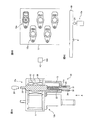
図4A及び図4Bは、アクチュエータユニットの構成例を示し、図4Aはアクチュエータユニットの長さ方向概略断面図、図4Bは図4Aの矢印A方向から見た概略平面図である。 4A and 4B show a configuration example of the actuator unit, FIG. 4A is a schematic sectional view in the length direction of the actuator unit, and FIG. 4B is a schematic plan view seen from the direction of arrow A in FIG. 4A.
図4Bは、ヨーク11において、複数のアクチュエータユニット12a,12b…が保持されたアクチュエータアセンブリを示す。各アクチュエータユニット12a、12b…は、例えばピアノ等の鍵盤楽器の各鍵に夫々対応して具備され、演奏者の鍵操作に対して任意のタッチ感(反力)を与えることに利用される。
FIG. 4B shows an actuator assembly in which a plurality of
図4Aにおいて、1つのアクチュエータユニット12aが、その縦軸方向についての断面図によって、その構造を詳細に示されている。各アクチュエータユニット12a、12b…は、同様に構成されるもので、以下の説明においては、アクチュエータ12aの構成要素についてのみ符号をとり、他を代表するものとする。
In FIG. 4A, the structure of one
アクチュエータユニット12aは、大別して、電磁ソレノイドからなるアクチュエータ部20と、アクチュエータ部20の可動子の動作位置及び動作速度を検出するための位置速度センサ部30とから構成される。位置速度センサ部30として、上記実施例の位置速度検出装置を応用することができる。
The
アクチュエータ部20は、その周囲をヨーク11に覆われており、各アクチュエータユニット12a,12b…の各アクチュエータ部が、当該ヨーク11内に配設されることで、複数のアクチュエータユニット12a、12b…はヨーク11に共通に保持されることとなる。アクチュエータユニット12a(12b…)は、ヨーク11の底面においてネジ止め固定されたケーシング部材13を有する。
The
アクチュエータ部20は、ヨーク11内に配置された電磁ソレノイドコイル21と、コイル21軸心内に、双方向的直線移動可能に挿入された棒状のプランジャ(可動子)22を有する。コイル21は、軸心が上下方向を指向する向きで配設され、その上下端がヨーク11の上面及び底面に設けられた貫通孔に連なることで、当該貫通孔におけるプランジャ22の貫通を許す。プランジャ22の上端からは、シャフト23がプランジャ22と同軸に延び、このシャフト23の先端に、対応する鍵に接触すべきシャフトヘッド24が具わる。
The
また、プランジャ22は、ケーシング部材13内に配設されたバネ25によって、常時上向きに付勢されており、通常のアクチュエータ非駆動時(電磁コイル21の通電オフ状態)においても、バネ25の付勢力によって図4Aに示すような上死点位置に保持されるようになっている。バネ25は、プランジャ22が自重によって下がらないように支えるためのもので、その付勢力は、プランジャ22の重みを支えるのに必要な強さだけ有し、それ以上は余分な負荷が加わらない強さであることが好ましい。
The
図示の例では、アクチュエータユニット12aは、タッチ付加用のアクチュエータとして構成されているため、プランジャ22を下から支えるバネ25が具備されている。このアクチュエータユニット12aにおけるタッチ付加制御時の動作説明は後述する。なお、当該アクチュエータの用途によっては(例えば、鍵の駆動用のアクチュエータとして装置する場合等)、このバネ25はなくてもよい。
In the illustrated example, the
プランジャ22の下端部には、位置速度センサ部30の一構成要素たる棒状の磁石部材31が、プランジャ22と同軸に延設される。ケーシング部材13底面には、磁石部材31の貫通を許す孔部31aが設けられており、磁石部材31はそこを貫通している。すなわち、位置速度センサ部30の一構成要素たる磁石部材31は、プランジャ22に対して同軸的に連結されることでユニット化され、且つ、プランジャ22の直線移動と一体的に運動する。
At the lower end of the
ボビン32は、長さ方向がプランジャ22の直線移動方向に沿う向きで、下部ケーシング部材13の下面に設置されており、その上端開口部が孔部31aに連なり、磁石部材31の侵入を許している。磁石部材31は、プランジャ22が直線変位すると、その変位と一体的に、ボビン32に対して相対的に侵入/後退動作する。
The
ボビン32の内面上に位置検出用磁気センサ33が配置されているとともに、ボビン32の外面上に速度検出用コイル34が巻回されている。磁石部材31は、上述のように、位置検出用磁石と速度検出用磁石とを含んで構成され、位置検出用磁気センサ33が、位置検出用磁石の磁気パターンに対向する。位置検出用磁気センサ33及び速度検出用コイル34の出力信号から、それぞれ、磁石部材31の位置及び速度が検出される。磁石部材31は、プランジャ22及びシャフトヘッド24と一体的に移動するので、プランジャ22及びシャフトヘッド24の位置及び速度が得られる。
A position detection
図4Bに示すように、アクチュエータユニット12a、12b…は、互いに隣接するもの同士の相対的位置を2列分散的(千鳥状)に違えて配列されている。アクチュエータユニット12a、12b…の各構成要素が、小型且つシンプルな構成で実現できるので、上記配置例が可能となる。千鳥状配列により、互いに隣接する各アクチュエータユニット12a、12b…の相互間隔を十分に広くとることができるので、各ユニット12a、12b…のソレノイドコイルが共通ヨーク11に覆われていても、磁気干渉による動作不整は防止される。
As shown in FIG. 4B, the
図4Cは、本応用例の鍵盤楽器における鍵とアクチュエータユニットとの配置関係を概略的に示すダイアグラムである。複数の鍵の1つを代表させて示す。他の鍵についても同様である。鍵40は、回動軸41を中心に回動するシーソー型の構造を有する。シャフトヘッド24が対応する鍵40の下面側の、回動軸41の手前(演奏者側)の位置に当接するように、アクチュエータユニット12aが配置されている。この例の鍵盤楽器には、アコースティックピアノにあるようなアクション機構が備えられておらず、適当な押離鍵反力は専らアクチュエータユニットによって得られる。
FIG. 4C is a diagram schematically showing an arrangement relationship between keys and actuator units in the keyboard musical instrument of this application example. One of a plurality of keys is shown as a representative. The same applies to other keys. The key 40 has a seesaw-type structure that rotates around a
アクチュエータユニット12aにより、対応する鍵にタッチ付加を行う動作について説明する。アクチュエータユニット12aは、通常時(非駆動時)から図4Aに示すように、プランジャ22がコイル21内に進入した状態にある。このとき、シャフトヘッド24の先端は対応する鍵(レスト位置にある)に当接しており、演奏者が当該鍵を押鍵操作すると、これに連動して、プランジャ22は下方へ変位しうる。
The operation of touching the corresponding key with the
アクチュエータ部20に対して、ドライバ100から駆動信号(電流)が供給され、コイル21が通電されると、コイル21にはプランジャ22を吸引する力が生じるので、当該プランジャ22にはコイル21内に引き留まろうとする力が作用する。これにより、当該鍵の押鍵に対して反力を与え、操作者に対して鍵操作のタッチ感を与える。アクチュエータ部20に供給される駆動信号を可変することで、プランジャ22を吸引する力を適切に制御し、押鍵操作に対して任意のタッチを付加できる。例えば、アコースティックピアノのようなハンマやアクション部材のない機構の鍵盤であっても、これらがあるかのようなタッチで演奏を行うことができる。
When a drive signal (current) is supplied from the
アクチュエータによるタッチ付加制御を的確且つ高精度で実現するには、プランジャ22の動きをセンシングして得るところのフィードバック信号(検出信号)の質が極めて重要な要素となる。実施例の位置速度検出装置を応用したアクチュエータユニット12aでは、プランジャ22の位置情報及び速度情報を同時に実測でき、この2つの実測値をフィードバック信号として利用することができる。これにより、精度の高いフィードバック制御を実現することができ、タッチ付加制御の性能を向上させることができる。
In order to realize the touch addition control by the actuator accurately and with high accuracy, the quality of the feedback signal (detection signal) obtained by sensing the movement of the
なお、タッチ付加のためにアクチュエータを駆動する力Fは、下記運動方程式によって与えられる(特開2005−195619号公報の「発明を実施するための最良の形態」の欄参照)。
F=MX”+ΡX’+KX・・・(式1)
(式1)において、Xは位置情報、X’は速度情報、X”は加速度情報、Mは質量、Ρは粘性係数、Kはバネ係数である。本応用例のアクチュエータユニットでは、位置速度センサ部30において位置情報X及び速度情報X’が実測される。加速度情報X”は、実測された速度情報X’を用いて算出することができる。
Note that the force F for driving the actuator for touch addition is given by the following equation of motion (see the column “Best Mode for Carrying Out the Invention” in Japanese Patent Laid-Open No. 2005-195619).
F = MX ″ + ΡX ′ + KX (Formula 1)
In (Expression 1), X is position information, X ′ is speed information, X ″ is acceleration information, M is mass, Ρ is a viscosity coefficient, and K is a spring coefficient. In the actuator unit of this application example, the position speed sensor The position information X and the speed information X ′ are actually measured in the
例えば、特開2005−195619号公報の「実施例1」が開示するような演奏操作子用アクチュエータユニットでは、位置検出のための位置検出装置と、速度検出のための速度検出装置とが別々に必要となるが、本応用例のアクチュエータユニットでは、1つの検出装置で位置及び速度を同時検出することができる。 For example, in a performance operator actuator unit as disclosed in “Example 1” of Japanese Patent Application Laid-Open No. 2005-195619, a position detection device for position detection and a speed detection device for speed detection are separately provided. Although necessary, in the actuator unit of this application example, the position and the speed can be detected simultaneously by one detection device.
なお、演奏者の鍵操作に対して所望のタッチ感を与える応用例について説明したが、実施例の位置速度検出装置は、自動演奏ピアノに応用することもできる。自動演奏ピアノでは、各鍵の奥側下方に配置したアクチュエータユニットのプランジャで鍵を突き上げることにより、無人の押鍵操作が行われる。自動演奏ピアノにおいて、鍵を駆動する力を精度よくフィードバック制御するために、プランジャの位置情報と速度情報とが利用される。自動演奏ピアノの鍵駆動用アクチュエータユニットにも、実施例の位置速度検出装置を組み込むことができる。 In addition, although the application example which gives a desired touch feeling with respect to a player's key operation was demonstrated, the position speed detection apparatus of an Example can also be applied to an automatic performance piano. In an automatic performance piano, an unattended key pressing operation is performed by pushing up a key with a plunger of an actuator unit arranged on the lower side of each key. In an automatic performance piano, the position information and speed information of the plunger are used to accurately feedback control the force for driving the key. The position / velocity detecting device of the embodiment can also be incorporated in the key driving actuator unit of the automatic performance piano.
また例えば、電子ピアノ等の鍵盤楽器のペダルに対し、例えばアコースティックピアノのダンパーペダルの操作感に似た感触を付与するために、実施例の位置速度検出装置を組み込んだアクチュエータユニットを配置することもできる。 In addition, for example, an actuator unit incorporating the position / velocity detection device of the embodiment may be arranged for a pedal of a keyboard instrument such as an electronic piano in order to give a feeling similar to that of a damper pedal of an acoustic piano, for example. it can.
なお、鍵やペダル以外にも、楽器に用いられるピッチベンドホイール等の操作子や、さらに楽器に限らずゲーム機等に用いられる他の操作子に対し、操作感付与や自動操作を行うアクチュエータに、実施例の位置速度検出装置を組み込むことができる。 In addition to keys and pedals, actuators such as pitch bend wheels used for musical instruments, and actuators that give operational feeling and automatic operation to other operators used for game machines etc. The position / velocity detecting device of the embodiment can be incorporated.
実施例の位置速度検出装置は、さらに、位置情報及び速度情報の双方を制御情報として利用する制御機構に広く応用することができる。例えば、車両のサスペンション制御に応用して安定走行に寄与することや、プリンタの動作制御に応用して高速かつ静かなプリント動作を行うことや、調理や調剤等に用いられる攪拌機器の良好な制御に寄与することができよう。 The position / velocity detection apparatus of the embodiment can be widely applied to a control mechanism that uses both position information and speed information as control information. For example, it can be applied to vehicle suspension control to contribute to stable running, it can be applied to printer operation control to perform high-speed and quiet printing operations, and good control of agitation equipment used for cooking, dispensing, etc. Can contribute.
以上実施例に沿って本発明を説明したが、本発明はこれらに制限されるものではない。例えば、種々の変更、改良、組み合わせ等が可能なことは当業者に自明であろう。 Although the present invention has been described with reference to the embodiments, the present invention is not limited thereto. It will be apparent to those skilled in the art that various modifications, improvements, combinations, and the like can be made.
1 ボビン
2 速度検出用コイル
3 磁石部材
3a 速度検出用磁石
3b 位置検出用磁石
4 位置検出用磁気センサ
5 磁気シールド部材
DESCRIPTION OF SYMBOLS 1
Claims (5)
内部に前記磁石部材が入り込んだコイルと、
前記コイルの内部に、前記第2の磁石と対向して配置された磁気センサと、
前記コイルに対し相対的に前記磁石部材が前記延在方向に関して移動可能となるように、該コイル及び該磁石部材の少なくとも一方を保持する保持機構と
を有するセンサ。 A first magnet having a shape extending in a predetermined direction and having magnetic poles of opposite polarities disposed at both ends, and a magnetic pole extending in a pattern in which the polarity is repeatedly reversed in a region on the side surface away from the both ends A magnet member including a second magnet arranged in a line;
A coil containing the magnet member inside;
A magnetic sensor disposed inside the coil and facing the second magnet;
A sensor having a holding mechanism for holding at least one of the coil and the magnet member such that the magnet member can move in the extending direction relative to the coil.
Priority Applications (1)
| Application Number | Priority Date | Filing Date | Title |
|---|---|---|---|
| JP2008231093A JP5266986B2 (en) | 2008-09-09 | 2008-09-09 | Sensor |
Applications Claiming Priority (1)
| Application Number | Priority Date | Filing Date | Title |
|---|---|---|---|
| JP2008231093A JP5266986B2 (en) | 2008-09-09 | 2008-09-09 | Sensor |
Publications (2)
| Publication Number | Publication Date |
|---|---|
| JP2010066065A true JP2010066065A (en) | 2010-03-25 |
| JP5266986B2 JP5266986B2 (en) | 2013-08-21 |
Family
ID=42191777
Family Applications (1)
| Application Number | Title | Priority Date | Filing Date |
|---|---|---|---|
| JP2008231093A Expired - Fee Related JP5266986B2 (en) | 2008-09-09 | 2008-09-09 | Sensor |
Country Status (1)
| Country | Link |
|---|---|
| JP (1) | JP5266986B2 (en) |
Cited By (4)
| Publication number | Priority date | Publication date | Assignee | Title |
|---|---|---|---|---|
| JP2013195327A (en) * | 2012-03-22 | 2013-09-30 | Okuma Corp | Position detector |
| JP2015039966A (en) * | 2013-08-22 | 2015-03-02 | ボッシュ株式会社 | Reservoir tank and brake device using the same |
| CN104464704A (en) * | 2014-12-17 | 2015-03-25 | 赖志强 | Intelligent piano |
| JP2017515110A (en) * | 2014-04-29 | 2017-06-08 | デーナ、オータモウティヴ、システィムズ、グループ、エルエルシー | Non-contact sensor for electromagnetic actuator assembly |
Citations (4)
| Publication number | Priority date | Publication date | Assignee | Title |
|---|---|---|---|---|
| JPH05505883A (en) * | 1990-12-05 | 1993-08-26 | ムーヴィング マグネット テクノロジィーズ エス.エイ. | Magnetic position and velocity sensor with Hall element |
| JP2000161986A (en) * | 1998-12-01 | 2000-06-16 | Robert Bosch Gmbh | Method and apparatus for measuring displacements |
| JP2009008638A (en) * | 2007-06-01 | 2009-01-15 | Murata Mach Ltd | Linear absolute displacement sensor |
| JP2009121967A (en) * | 2007-11-15 | 2009-06-04 | Iai:Kk | Absolute type linear encoder and actuator |
-
2008
- 2008-09-09 JP JP2008231093A patent/JP5266986B2/en not_active Expired - Fee Related
Patent Citations (4)
| Publication number | Priority date | Publication date | Assignee | Title |
|---|---|---|---|---|
| JPH05505883A (en) * | 1990-12-05 | 1993-08-26 | ムーヴィング マグネット テクノロジィーズ エス.エイ. | Magnetic position and velocity sensor with Hall element |
| JP2000161986A (en) * | 1998-12-01 | 2000-06-16 | Robert Bosch Gmbh | Method and apparatus for measuring displacements |
| JP2009008638A (en) * | 2007-06-01 | 2009-01-15 | Murata Mach Ltd | Linear absolute displacement sensor |
| JP2009121967A (en) * | 2007-11-15 | 2009-06-04 | Iai:Kk | Absolute type linear encoder and actuator |
Cited By (4)
| Publication number | Priority date | Publication date | Assignee | Title |
|---|---|---|---|---|
| JP2013195327A (en) * | 2012-03-22 | 2013-09-30 | Okuma Corp | Position detector |
| JP2015039966A (en) * | 2013-08-22 | 2015-03-02 | ボッシュ株式会社 | Reservoir tank and brake device using the same |
| JP2017515110A (en) * | 2014-04-29 | 2017-06-08 | デーナ、オータモウティヴ、システィムズ、グループ、エルエルシー | Non-contact sensor for electromagnetic actuator assembly |
| CN104464704A (en) * | 2014-12-17 | 2015-03-25 | 赖志强 | Intelligent piano |
Also Published As
| Publication number | Publication date |
|---|---|
| JP5266986B2 (en) | 2013-08-21 |
Similar Documents
| Publication | Publication Date | Title |
|---|---|---|
| JP2009098582A (en) | Drive unit | |
| US8773114B2 (en) | Apparatus for detecting displacement of electromagnetic actuator | |
| JP5266986B2 (en) | Sensor | |
| JP5098712B2 (en) | Locking device | |
| JP2006153879A (en) | Linear position sensor | |
| US8319089B2 (en) | Oscillatory, magnetically activated position sensor | |
| WO2021100448A1 (en) | Detection system, musical performance operating device, and keyboard instrument | |
| US8859877B2 (en) | Damper drive device for musical instrument, and musical instrument | |
| JP3352366B2 (en) | Pulse signal generator | |
| US20080229904A1 (en) | Key Actuating Apparatus | |
| JPH11150450A (en) | Pulse signal generating device | |
| JP2007085888A (en) | Controlled variable input apparatus | |
| JP4790802B2 (en) | Actuator | |
| CN109937390B (en) | Drive control device for actuator | |
| Van Rooyen et al. | Voice coil actuators for percussion robotics. | |
| JP5217554B2 (en) | Keyboard device | |
| JP4736210B2 (en) | Sensor | |
| JP4254891B2 (en) | Performance information acquisition device | |
| JP2010113025A (en) | Electronic keyboard instrument | |
| JP2010134728A (en) | Input device providing sensation of operation | |
| JP2008304954A (en) | Keyboard instrument provided with actuator unit for performance operation element and assembly of actuator unit | |
| JP5573114B2 (en) | Performance controller drive unit | |
| JP2010025784A (en) | Speed measuring apparatus | |
| JP4665956B2 (en) | Performance information acquisition device | |
| JP3591576B2 (en) | Operator mechanism for electronic musical instruments and musical sound control |
Legal Events
| Date | Code | Title | Description |
|---|---|---|---|
| A621 | Written request for application examination |
Free format text: JAPANESE INTERMEDIATE CODE: A621 Effective date: 20110823 |
|
| A131 | Notification of reasons for refusal |
Free format text: JAPANESE INTERMEDIATE CODE: A131 Effective date: 20121113 |
|
| A521 | Written amendment |
Free format text: JAPANESE INTERMEDIATE CODE: A523 Effective date: 20121214 |
|
| TRDD | Decision of grant or rejection written | ||
| A01 | Written decision to grant a patent or to grant a registration (utility model) |
Free format text: JAPANESE INTERMEDIATE CODE: A01 Effective date: 20130409 |
|
| A61 | First payment of annual fees (during grant procedure) |
Free format text: JAPANESE INTERMEDIATE CODE: A61 Effective date: 20130422 |
|
| R150 | Certificate of patent or registration of utility model |
Free format text: JAPANESE INTERMEDIATE CODE: R150 |
|
| LAPS | Cancellation because of no payment of annual fees |