JP2010064824A - Paper feeder - Google Patents
Paper feeder Download PDFInfo
- Publication number
- JP2010064824A JP2010064824A JP2008231278A JP2008231278A JP2010064824A JP 2010064824 A JP2010064824 A JP 2010064824A JP 2008231278 A JP2008231278 A JP 2008231278A JP 2008231278 A JP2008231278 A JP 2008231278A JP 2010064824 A JP2010064824 A JP 2010064824A
- Authority
- JP
- Japan
- Prior art keywords
- roller
- paper
- feed roller
- sensor
- sheet
- Prior art date
- Legal status (The legal status is an assumption and is not a legal conclusion. Google has not performed a legal analysis and makes no representation as to the accuracy of the status listed.)
- Granted
Links
Images


Abstract
Description
本発明は、例えばホッパテーブルに積載された帳票等の紙葉類を、光学的帳票読取装置などの紙葉類処理装置の内部へ一枚ずつ取り込む給紙装置に関する。 The present invention relates to a paper feeding device that takes in paper sheets such as a form loaded on a hopper table one by one into a paper sheet processing apparatus such as an optical form reading apparatus.
ホッパテーブルに積載した帳票等を装置内部の搬送路に取り込み、搬送路に設けられた光学読み取り部により帳票に記された文字や図形等をイメージとして読み取る紙葉類移動型の光学的帳票読取装置、つまりシートフェッド型光学的帳票読取装置が知られている。 A paper-sheet-moving optical form reading device that takes in a form, etc., loaded on a hopper table into a conveyance path inside the apparatus, and reads characters, figures, etc. written on the form as an image by an optical reading unit provided in the conveyance path. That is, a sheet-fed optical form reading apparatus is known.
従来のシートフェッド型光学的帳票読取装置は、ホッパテーブルから帳票類を取り込む際、重送を防止するため、給紙機構にフィードローラに対向したセパレートローラを常に逆転させ、フィードローラ側のワンウェイクラッチ〜カラー間のガタ分だけフィードローラも逆転させることで、ホッパテーブル側へ2枚目の帳票を戻すようにしていた(例えば特許文献1参照)。
このように従来は、重送を防止するためセパレートローラを逆転させ、フィードローラ側のワンウェイクラッチ〜カラー間のガタ分だけ逆転していたために、フィードローラ側の従動が十分ではなく、重送した2枚目の帳票が正しく戻らないことがあった。 Thus, conventionally, the separate roller was reversed to prevent double feed, and the feed roller side was reverse by the amount of backlash between the one-way clutch and the collar. The second form may not return correctly.
本発明はこのような課題を解決するためになされたもので、ホッパテーブルに積載された紙葉類を装置内に一枚ずつ取り込む際に、1枚目の紙葉類とともに分離部に連れ込まれた2枚目以降の紙葉類の重送を防止しつつ分離された2枚目以降の紙葉類をホッパテーブルに確実に戻し、所望のタイミングで2枚目以降の紙葉類を取り込むことができる給紙装置を提供することを目的とする。 The present invention has been made to solve such a problem, and when taking the paper sheets loaded on the hopper table one by one into the apparatus, the paper sheets are taken together with the first paper sheet to the separation unit. The second and subsequent sheets are reliably returned to the hopper table while the second and subsequent sheets are prevented from being double fed, and the second and subsequent sheets are taken in at a desired timing. It is an object of the present invention to provide a paper feeding device that can perform printing.
上記した目的を達成するために、本発明の給紙装置は、紙葉類が積載されたホッパテーブルと、前記紙葉類を前記ホッパテーブルから装置内へ繰り出すピックアップローラと、内輪と外輪とを有し、前記内輪が逆転したときに前記外輪が空転するワンウェイクラッチを内蔵したフィードローラと、このフィードローラの下方に対向配置されたセパレートローラとを有し、前記ピックアップローラにより繰り出された紙葉類を前記フィードローラと前記セパレートローラとで挟持し、前記フィードローラが正転するのに対して前記セパレートローラを停止または逆転させることで、複数の紙葉類が繰り出されてきた場合に前記紙葉類を一枚ずつ分離して繰り出す分離部と、前記フィードローラの前記内輪を正転、停止、逆転させるように駆動する駆動部と、前記分離部の搬送方向下流に設けられ、前記紙葉類の紙厚を検出する紙厚検知部と、前記紙厚検知部と前記分離部との間に設けられ、この位置を通過する前記紙葉類を検知する第1センサと、前記紙厚検知部の搬送方向下流に設けられ、この位置を通過する前記紙葉類を検知する第2センサと、これら第1センサ及び第2センサによる前記紙葉類の検知または非検知の状態を監視し、少なくとも前記第1センサが前記紙葉類を検知したときに、前記紙葉類の取り込み期間中でないときに、前記フィードローラの前記内輪を逆転させるように前記駆動部を制御するコントローラとを具備する。 In order to achieve the above-described object, a paper feeding device of the present invention includes a hopper table on which paper sheets are stacked, a pickup roller that feeds the paper sheets from the hopper table into the device, an inner ring, and an outer ring. A paper roller having a built-in one-way clutch in which the outer ring is idled when the inner ring rotates in reverse, and a separate roller disposed opposite to the feed roller, the sheet being fed by the pickup roller. When a plurality of sheets are fed out by holding the sheet between the feed roller and the separation roller and stopping or reversing the separation roller while the feed roller rotates normally A separation unit that separates and feeds leaves one by one, and the inner ring of the feed roller is driven to rotate forward, stop, and reverse. A drive unit, a paper thickness detection unit provided downstream of the separation unit in the transport direction, for detecting the paper thickness of the paper sheet, and provided between the paper thickness detection unit and the separation unit; A first sensor for detecting the paper sheet passing therethrough, a second sensor provided downstream of the paper thickness detection unit in the transport direction and detecting the paper sheet passing through the position, the first sensor and the first sensor The state of detection or non-detection of the paper sheet by two sensors is monitored, and at least when the first sensor detects the paper sheet and when the paper sheet is not being taken in, the feed roller And a controller for controlling the drive unit so as to reverse the inner ring.
本発明の給紙装置は、紙葉類が積載されたホッパテーブルと、前記紙葉類を前記ホッパテーブルから装置内へ繰り出すピックアップローラと、駆動軸とその外側にコロを介して回動自在に設けられたローラ部とを有し、前記駆動軸が逆転したときに前記ローラ部が空転するワンウェイクラッチを内蔵したフィードローラと、前記フィードローラの下方に対向配置されたセパレートローラとを有し、前記ピックアップローラにより繰り出された紙葉類を前記フィードローラと前記セパレートローラとで挟持し、前記フィードローラが正転するのに対して前記セパレートローラを停止または逆転させることで、複数の紙葉類が繰り出されてきた場合に最上部の紙葉類とこの紙葉類に連れ込まれた2枚目以降の紙葉類とを分離して前記最上部の紙葉類を繰り出す分離部と、前記フィードローラの前記駆動軸を正転、停止、逆転させるように駆動する駆動部と、ドライブローラとピンチローラを上下に対向させ、かつ互いが当接するように前記分離部の搬送方向下流に設ける一方、前記紙葉類が前記ドライブローラと前記ピンチローラとの間を通過するときに紙厚で上下に変位する前記ピンチローラの変位量を検出する変位センサを有する紙厚検知部と、前記紙厚検知部と前記分離部との間に設けられ、この位置を通過する前記紙葉類を検知する第1センサと、前記紙厚検知部の搬送方向下流に設けられ、この位置を通過する前記紙葉類を検知する第2センサと、これら第1センサ及び第2センサによる前記紙葉類の検知または非検知の状態を監視し、少なくとも前記第1センサが前記紙葉類を検知したときに、前記紙葉類の取り込み期間中でないときに、前記フィードローラの内輪を逆転させるように前記駆動部を制御するコントローラとを具備する。 A sheet feeding device according to the present invention includes a hopper table on which sheets are stacked, a pick-up roller for feeding the sheets from the hopper table into the apparatus, a drive shaft, and a roller on the outside thereof via a roller. A feed roller having a built-in one-way clutch that idles when the drive shaft rotates in reverse, and a separate roller disposed oppositely below the feed roller. A plurality of paper sheets can be obtained by holding the paper sheet fed by the pickup roller between the feed roller and the separation roller, and stopping or reversing the separation roller while the feed roller rotates normally. When the uppermost paper sheet is fed out, the uppermost paper sheet is separated from the second and subsequent paper sheets brought into the paper sheet. A separating unit that feeds the drive shaft of the feed roller so as to rotate forward, stop, and reverse, and the separating unit so that the drive roller and the pinch roller face each other vertically and abut each other. A paper thickness having a displacement sensor for detecting a displacement amount of the pinch roller that is displaced up and down by a paper thickness when the paper sheet passes between the drive roller and the pinch roller. A detection unit, a first sensor that is provided between the paper thickness detection unit and the separation unit and detects the paper sheets passing through the position; and a downstream of the paper thickness detection unit in the transport direction; A second sensor that detects the paper sheet that passes through this position, and a detection state or non-detection state of the paper sheet by the first sensor and the second sensor, and at least the first sensor detects the paper sheet. Upon detection of, when not busy period of the paper sheet, comprising a controller for controlling the driving unit so as to reverse the inner ring of the feed roller.
このように本発明によれば、ホッパテーブルに積載された紙葉類を装置内に一枚ずつ取り込む際に、1枚目の紙葉類とともに分離部に連れ込まれた2枚目以降の紙葉類の重送を防止しつつ分離された2枚目以降の紙葉類をホッパテーブルに確実に戻し、所望のタイミングで2枚目以降の紙葉類を取り込むことができる。 As described above, according to the present invention, when the sheets loaded on the hopper table are taken into the apparatus one by one, the second and subsequent sheets taken into the separation unit together with the first sheet. The second and subsequent paper sheets can be reliably returned to the hopper table while the second and subsequent paper sheets are taken in at a desired timing while preventing the double feeding of the paper.
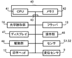
以下、本発明を実施するための最良の形態を図面に基づき説明する。図1は本発明の一つの実施の形態の光学的帳票読取装置の概観図、図2はこの光学的帳票読取装置の構成を概略的に示す側面図、図3はこの光学的帳票読取装置の制御系を機能的に示すブロック図である。 The best mode for carrying out the present invention will be described below with reference to the drawings. FIG. 1 is a schematic view of an optical form reading apparatus according to an embodiment of the present invention, FIG. 2 is a side view schematically showing the configuration of the optical form reading apparatus, and FIG. It is a block diagram which shows a control system functionally.
図1に示すように、この光学的帳票読取装置は、帳票取込口と帳票排出口が筐体1の前面部に設けられたものであり、帳票取込口から帳票P等の紙葉類を装置内部に取り込み循環型の搬送路を搬送しつつ帳票上に記された文字や図形等をイメージデータ(画像)として読み取り、情報を正常に読み取った帳票に対して印字処理などを施した上で帳票排出口から排出する紙葉類移動型の光学的帳票読取装置、つまりシートフェッド型光学的帳票読取装置である。
As shown in FIG. 1, this optical form reading apparatus has a form taking-in port and a form discharge opening provided on the front surface of the
筐体1の前面部には、ディスプレイ47と操作部48が設けられている。ディスプレイ47には、操作手順等の各種メニューと処理状況及びエラー内容等が表示される。操作部48には、帳票の処理開始や停止を指示したり、またエラーを解除したりするための釦類が設けられている。
A display 47 and an
この光学的帳票読取装置は、図2乃至図4に示すように、筐体1の側面から突出して設けられたホッパテーブル2(以下「ホッパ2」と称す)と、筐体1の帳票取込口付近に設けられた給紙部11と、この給紙部11の搬送方向下流に設けられた光学読取部14と、さらに搬送方向下流に設けられた印字ヘッド12、プラテンローラ18などを有する印字部と、帳票振分部としてのフラッパ13と、リジェクトスタッカ15、アクセプトスタッカ17と、装置内の各部に電力を供給する電源部19と、装置内の各部を制御するコントローラ40とを備えている。
As shown in FIGS. 2 to 4, the optical form reading apparatus includes a hopper table 2 (hereinafter referred to as “
また、図3に示すように、コントローラ40は、主にCPU41、メモリ42およびインターフェース43を有している。
インターフェース43には、この装置内の各部からの内部バスが接続されている。各部とは、光学読取部14、表示部としてのディスプレイ47、操作部48、モータ、ベルト、ギヤを含む駆動部44、変位センサ9、センサS1,S2、印字ヘッド12等である。
As shown in FIG. 3, the
An internal bus from each part in the apparatus is connected to the
ホッパ2は、筐体1の帳票取込口に昇降自在に設けられている。ホッパ2には、装置内部に取り込まれる帳票Pが多数積み重ねた状態で搭載される。
なお、帳票については、重送を考慮しない説明では単に帳票Pと表し、分離部6等のように重送を考慮する場合は、上から順に帳票P1,帳票P2等と表すものとする。
The
Note that the form is simply represented as a form P in the description not considering double feed, and when the double feed is considered like the separating unit 6 or the like, it is represented as a form P1, form P2, etc. in order from the top.
給紙部11は、帳票取込部としてのピックアップローラ3と、フィードローラ4およびセパレートローラ5を有する分離部6(図4参照)と、上部搬送用ローラとしてのピンチローラ8と下部搬送用ローラとしてのドライブローラ7と、ピンチローラ8の上に配置された変位センサ9とで構成される紙厚検出部10(図4参照)と、この紙厚検出部10の両側に配置された帳票通過検知用のセンサS1,S2とを備えている。
The
ピックアップローラ3は、上昇したホッパ2に積載された多数の帳票Pの最上面に当接し、駆動部44によって、図に向かって時計回りに回動されることで最上部の帳票Pをローラ表面の摩擦力で装置内部へ繰り出す(引き込む)。
The pickup roller 3 abuts on the uppermost surface of a large number of forms P stacked on the raised
分離部6は、フィードローラ4とこれに対向配置されたセパレートローラ5とで構成されている。フィードローラ4の駆動軸4aは、ピックアップローラ3のシャフト(図示せず)とギヤまたはタイミングベルト等で接続されており、軸自体は同方向に回動するが、フィードローラ4にワンウェイクラッチが内蔵されているため、ローラ自体の動きは異なる。
The separation unit 6 includes a feed roller 4 and a separate roller 5 disposed to face the feed roller 4. The
フィードローラ4は、ピックアップローラ3により装置内に引き入れられた帳票Pを光学読取部14が配置されている下流の方向へ送り込む駆動ローラである。フィードローラ4は、駆動軸4aとその外輪にローラ部4bとを有している(図6参照)。フィードローラ4はワンウェイクラッチ機構を内蔵し、駆動軸4aが逆転するときにローラ部4bが空転する(図6〜図9の説明で詳述)。
The feed roller 4 is a drive roller that feeds the form P drawn into the apparatus by the pickup roller 3 in a downstream direction where the
フィードローラ4とセパレートローラ5とは上下に対向配置されている。ピックアップローラ3により繰り出された帳票Pをフィードローラ4とセパレートローラ5とで挟持し、フィードローラ4が正転(図4の矢印A)方向に回転するのに対してセパレートローラ5を停止または逆転させることで、例えば複数の帳票P1,P2が重送されてきたときに最上部の第1帳票P1とこの第1帳票P1と繰り出された2枚目以降の第2帳票P2とを分離して第1帳票P1を前方(搬送方向)へ繰り出す。 The feed roller 4 and the separate roller 5 are arranged to face each other in the vertical direction. The form P fed out by the pickup roller 3 is sandwiched between the feed roller 4 and the separation roller 5, and the separation roller 5 is stopped or reversed while the feed roller 4 rotates in the forward direction (arrow A in FIG. 4). For example, when a plurality of forms P1 and P2 are double-fed, the uppermost first form P1 is separated from the first form P1 and the second and subsequent second forms P2 fed out. The first form P1 is fed forward (conveyance direction).
セパレートローラ5は、フィードローラ4に対して遅延して回動、または停止もしくは逆転するなどしてフィードローラ4と協働して、複数の帳票P1,P2…が重送してきたときに帳票Pを一枚ずつに分離した上で装置内部へ取り込む。 The separating roller 5 rotates with a delay relative to the feed roller 4, or cooperates with the feed roller 4 by stopping or reversing, for example, when a plurality of forms P1, P2,. Are taken into the device after separating them one by one.
紙厚検出部10のピンチローラ8及びドライブローラ7は、基準位置Tを挟んで上下に対向して配置されている。ドライブローラ7は駆動部44により回転駆動されてピンチローラ8とで帳票Pを挟んで引き込み搬送する。ドライブローラ7は、駆動部44により駆動されて、帳票Pをピンチローラ8と共に両面から挟持しつつ搬送する搬送機構の一部である。搬送機構は、この他、ベルト、ガイドレールなども備えており、帳票取込口のホッパ2からピックアップローラ3により筐体1の内部に取り込まれた帳票Pをほぼ半周させる。ピンチローラ8は、帳票Pがこの位置を通過する際に、ドライブローラ7とで挟んだ帳票Pの厚みに応じて帳票搬送方向と直交する方向(図の上下方向)に高さが変位、つまり移動するように設けられている。
The pinch roller 8 and the drive roller 7 of the paper thickness detection unit 10 are arranged to face each other up and down across the reference position T. The drive roller 7 is rotationally driven by the
光学読取部14以降に設けられている他のピンチローラ8及びドライブローラ7は、帳票Pの搬送経路を形成するように上下に対向し、図2のように装置内のそれぞれの部位(位置)に配置されている。
The other pinch rollers 8 and the drive rollers 7 provided after the
変位センサ9は、ピンチローラ8の変位量を検出するためにピンチローラ8の上面を検知する位置に設けられている。変位センサ9は、ピンチローラ8の高さ(上下方向の位置)の変位量を検知し、変位量を示す位置検知信号をコントローラ40へ送出する。CPU41は、変位センサ9からの位置検知信号を受けてその位置検知信号に含まれる変位量と予めメモリ42に設定された一枚の帳票の基準紙厚とを比較して帳票Aの重送検知(判定)を行う。基準紙厚は、例えば0.09mm±0.02mmなどといった範囲を持っている。
The displacement sensor 9 is provided at a position for detecting the upper surface of the pinch roller 8 in order to detect the amount of displacement of the pinch roller 8. The displacement sensor 9 detects a displacement amount at the height (vertical position) of the pinch roller 8 and sends a position detection signal indicating the displacement amount to the
センサS1,S2は、紙厚検出部10の両側に配置されている。センサS1,S2は、帳票位置検出用のセンサである。センサS1は、分離部6と紙厚検出部10との間に配置されている。センサS2は、紙厚検出部10と光学読取部14との間に配置されている。
センサS1,S2は、例えば遮光センサであり、搬送経路を跨ぐように発光器と受光器が配置されたものである。搬送経路上を帳票Pが搬送され、それぞれのセンサの設置位置に差し掛かると「暗」となり、帳票Pがその位置を通過すると「明」となり、それぞれの状況を示す検知信号がコントローラ40へ送られる。
The sensors S1 and S2 are arranged on both sides of the paper thickness detection unit 10. The sensors S1 and S2 are forms position detection sensors. The sensor S1 is disposed between the separation unit 6 and the paper thickness detection unit 10. The sensor S2 is disposed between the paper thickness detection unit 10 and the
Sensors S1 and S2 are, for example, light shielding sensors, and a light emitter and a light receiver are disposed so as to straddle the conveyance path. The form P is transported on the transport path and becomes “dark” when it reaches the installation position of each sensor, and becomes “bright” when the form P passes through that position, and a detection signal indicating each situation is sent to the
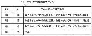
メモリ42には、図5に示すフィードローラ駆動軸制御テーブル51が記憶されており、センサS1,S2からの帳票の検知状況(検知信号の状況「明」、「暗」)がCPU41により常に管理されており、CPU41は、フィードローラ駆動軸制御テーブル51を参照して各センサにおける帳票Pの検知状況と、帳票Pの取り込みタイミングとの関係で駆動部44を制御し、フィードローラ4の駆動軸4aを、正転方向(矢印Aの方向)、停止、または逆転方向(矢印Bの方向)などに回転させる。
The
このフィードローラ駆動軸制御テーブル51では、例えばセンサS1,S2が共に「明」検知状態になった場合、取込タイミングならば、フィードローラ4の駆動軸4aを正転させ、取込タイミングでなければ、フィードローラ4の駆動軸4aを停止させる。
In the feed roller drive shaft control table 51, for example, when both the sensors S1 and S2 are in the “bright” detection state, the
またセンサS1が「暗」検知の状態、センサS2が「明」検知の状態になった場合、取込タイミングならば、フィードローラ4の駆動軸4aを正転させ、取込タイミングでなければ、フィードローラ4の駆動軸4aを逆転させる。
Also, when the sensor S1 is in the “dark” detection state and the sensor S2 is in the “bright” detection state, if it is the take-in timing, the
さらにセンサS1,センサS2が共に「暗」検知の状態になった場合、取込タイミングならば、フィードローラ4の駆動軸4aを停止させ、取込タイミングでなければ、フィードローラ4の駆動軸4aを逆転させる。
Further, when both of the sensors S1 and S2 are in the “dark” detection state, the
またセンサS1が「明」検知の状態、センサS2が「暗」検知の状態になった場合、取込タイミングにかかわらず、フィードローラ4の駆動軸4aを停止させる。
When the sensor S1 is in the “light” detection state and the sensor S2 is in the “dark” detection state, the
すなわち、CPU41は、フィードローラ駆動軸制御テーブル51を参照して駆動部44を制御してフィードローラ4の駆動軸4aを正転、停止、逆転させるように駆動する。
That is, the CPU 41 refers to the feed roller drive shaft control table 51 and controls the
CPU41は、センサS1及びセンサS2による帳票Pの検知または非検知の状態を監視し、少なくともセンサS1が帳票Pを検知したときに、帳票Pの取り込み期間中でないときに、フィードローラ4の駆動軸4aを逆転させるように駆動部44を制御する。
The CPU 41 monitors the state of detection or non-detection of the form P by the sensors S1 and S2, and at least when the sensor S1 detects the form P, and when the form P is not being taken in, the drive shaft of the feed roller 4 The
CPU41は、変位量が、一枚の帳票の基準紙厚の範囲を超えた場合は、重送と判定する。重送とは複数枚の帳票が重なって搬送されることを言う。
CPU41は、帳票の重送を検知した場合、ピックアップローラ3、フィードローラ4、セパレートローラ5、ドライブローラ7などを回転駆動する駆動部44を制御して帳票Pの給紙(搬入及び搬送)を制御する。
When the amount of displacement exceeds the range of the reference sheet thickness of one form, the CPU 41 determines that double feeding. Double feeding means that a plurality of forms are transported in an overlapping manner.
When the CPU 41 detects double feeding of a form, the CPU 41 controls the
光学読取部14は、給紙部11の下流の搬送路に設けられている。光学読取部14は、搬送経路上を搬送される帳票Pから画像を読み取る画像読取ユニットであり、例えば密着型のCCDラインセンサ(密着センサ)などである。
The
印字ヘッド12は、搬送経路の下流の帳票排出口に近い位置に設けられている。印字ヘッド12は、プラテンローラ18に対向して設けられている。印字ヘッド12と対向配置されたプラテンローラ18とを合わせて印字部と称す。印字ヘッド12は、光学読取部14により情報が正常に読み取られた帳票に対して、例えば整理番号や処理済みを示すマーク等を印字する。具体的には、印字ヘッド12は、正常に読み取り済みの帳票に対して、例えば連続番号等を印字する。
The
フラッパ13は、印字ヘッド12より搬送方向下流(帳票排出口手前)に設けられ、CPU41により制御される。フラッパ13は、コントローラ40により制御されて、帳票Pをリジェクトスタッカ15またはアクセプトスタッカ17の方向に振り分ける。
リジェクトスタッカ15は、読み取り処理が正常に行わなかった帳票Pが集積される帳票集積部である。アクセプトスタッカ17は、読み取り処理が正常に行われた帳票Pが集積される帳票集積部である。
The
The
CPU41は、紙厚検出部10の前後に配置されたセンサS1及びセンサS2が先行する第1帳票である帳票P1を非検知「明」または検知「暗」した状態と、帳票P1の画像読み取り状況とを基に、帳票P1と共に分離部6に取り込まれた第2帳票である2枚目以降の帳票P2の取り込みタイミングか否かを判定する。この判定の結果、帳票P2の取り込みタイミングではない場合、CPU41は、フィードローラ4の駆動軸4aを逆転させるように駆動部44を制御する。
The CPU 41 detects that the form P1 which is the first form preceded by the sensors S1 and S2 arranged before and after the paper thickness detection unit 10 is not detected “bright” or detected “dark”, and the image reading state of the form P1. Based on the above, it is determined whether or not it is the timing of taking in the second and subsequent forms P2, which is the second form taken into the separation unit 6 together with the form P1. As a result of the determination, if it is not the timing for taking in the form P2, the CPU 41 controls the
なお、取り込みタイミングは、フィードローラ4を正転(ピックアップローラ3で帳票の取り込みを開始)させてから、センサS2が「暗」検知してフィードローラ4を停止させるまでの期間であり、この期間、CPU41は、フィードローラ駆動軸制御テーブル51を参照し、取り込みタイミングであるものとして、センサS1,S2の検知状態に応じてフィードローラ4の駆動軸4aを、正転(矢印A)方向に回動または停止させるよう駆動部44を制御する。
取り込みタイミング以外の期間、つまり非取込期間、CPU41は、センサS1,S2の検知状態に応じてフィードローラ4の駆動軸4aを、逆転(矢印B)方向に回動または停止させるよう駆動部44を制御する。
The take-in timing is a period from when the feed roller 4 is rotated forward (take-up of the form by the pickup roller 3) to when the sensor S2 detects “dark” and the feed roller 4 is stopped. The CPU 41 refers to the feed roller drive axis control table 51 and rotates the
During a period other than the capture timing, that is, the non-capture period, the CPU 41 drives or rotates the
図6乃至図9を参照してフィードローラ4のワンウェイクラッチ機構について説明する。
図6に示すように、フィードローラ4は、駆動軸4aとその外側で回転自在な外輪としてのローラ部4bと、駆動軸4aとローラ部4b間に介挿された球形のコロ4cと、コロ4cを駆動軸4aとローラ部4bとの間にほぼ均等に配置するための隔離部材4dとを有している。
ローラ部4bには、コロ4cを収容するための凹部が設けられており、凹部の一方の壁面は垂直に形成され、駆動軸4aとローラ部4bの間はコロ4cの直径に相当する高さを有する。他方の壁面は斜めに形成され、駆動軸4aとローラ部4bとの間はコロ4cの直径よりも低い。
The one-way clutch mechanism of the feed roller 4 will be described with reference to FIGS.
As shown in FIG. 6, the feed roller 4 includes a
The
外輪のローラ部4bと内輪の駆動軸4aが同じ速度で回転する場合、図7に示すように、コロ4cの移動はほぼない。
一方、内輪の駆動軸4aの回転速度に対して外輪のローラ部4bの回転速度が速い場合、ローラ部4bの回転方向とは逆側に移動し、図8ではコロ4cを右側の斜めの壁面に押しつける形になり、ロックする。
また、内輪の駆動軸4aの回転速度に対して外輪のローラ部4bの回転速度が遅い場合、ローラ部4bの回転方向に移動し、図9ではコロ4cを左側の垂直な壁面に当接する。駆動軸4aとローラ部4bがコロ4cを狭持しないため、コロ4cは回転する。
When the outer
On the other hand, when the rotational speed of the
Further, when the rotation speed of the
以下、図10のフローチャートを参照してこの光学的帳票読取装置の動作を説明する。
この光学的帳票読取装置では、操作部48より処理開始の指示コマンドの入力があった場合、コントローラ40は、ホッパ2を上昇させるためのモータを制御して駆動し、ピックアップローラ3を正転方向へ回転させ、ホッパテーブル2を上昇させる(図10のステップS101)。
The operation of this optical form reading apparatus will be described below with reference to the flowchart of FIG.
In this optical form reading apparatus, when an instruction command for starting processing is input from the
そして、ホッパ2上に積載された帳票類Pのうちの最上部の帳票Pが、ピックアップするのに最適な高さになった基準位置Tでピックアップローラ3に当接し、この位置で、コントローラ40は、ホッパ2の上昇を停止させる(ステップS102)。
ここで、回転しているピックアップローラ3により最上部の帳票Pが繰り出される。
The uppermost form P of the forms P loaded on the
Here, the uppermost form P is fed out by the rotating pickup roller 3.
ホッパ2を停止後、コントローラ40は、フィードローラ4の駆動軸4aを正転(矢印A方向に回動)し、セパレートローラ5を矢印C方向に回動するよう駆動部44を制御する。これにより、フィードローラ4は、正転(矢印A方向に回転)し、セパレートローラ5は矢印C方向に回転する。これにより、ピックアップローラ3により繰り出された帳票Pが装置内に取り込まれる(ステップS103)。
帳票Pの取り込み動作は、停止を指示するコマンドが入力されるか、または帳票Pがホッパ2からなくなるまで繰り返される。
After stopping the
The operation of taking in the form P is repeated until a command for instructing the stop is input or the form P is removed from the
ここで、繰り出されてきた帳票Pが重送(帳票P1,P2の2枚が重なった状態)であったとする。複数枚の帳票P1,P2がフィードローラ4とセパレートローラ5との間に挟まれる。 Here, it is assumed that the form P that has been fed out is a double feed (a state in which the two forms P1 and P2 are overlapped). A plurality of forms P1 and P2 are sandwiched between the feed roller 4 and the separation roller 5.
このときには、帳票Pは、まだセンサS1,S2の位置に達していないため、センサS1,S2の検知状態は、共に「明」、「明」であり、かつ帳票取込動作を開始したばかりの取込タイミングである。コントローラ40は、フィードローラ駆動軸制御テーブル51に従ってフィードローラ4の駆動軸4aを正転させる。フィードローラ4とセパレートローラ5とで最上面の帳票P1とその下の帳票P2が別々の方向に擦られるため、互いが分離され、最上面の帳票P1一枚が搬送方向(下流)へ送り出される。
At this time, since the form P has not yet reached the position of the sensors S1 and S2, the detection states of the sensors S1 and S2 are both “bright” and “bright”, and the form taking-in operation has just started. This is the capture timing. The
帳票P1に続き、次の帳票P2…というように帳票が順に繰り出されてゆくに従ってピックアップローラ3の高さが下がってくると、ホッパ2に設けられた昇降機構は、ピックアップに最適な高さになるまでホッパ2を上方に持ち上げるので、帳票Pの繰り出し高さ(基準位置T)が常に維持され、帳票Pの繰り出し動作を連続的に行う。
When the height of the pickup roller 3 is lowered as the form is successively fed out, such as the next form P2, following the form P1, the lifting mechanism provided in the
分離部6から送り出された1枚の帳票P1は、センサS1の位置を通過する。帳票P1がセンサS1の位置を通過中、センサS1は帳票P1により遮光されるので、センサS1から「暗」信号がコントローラ40へ出力される(ステップS104)。 One form P1 sent out from the separation unit 6 passes the position of the sensor S1. While the form P1 passes the position of the sensor S1, the sensor S1 is shielded from light by the form P1, so that a “dark” signal is output from the sensor S1 to the controller 40 (step S104).
紙厚検出部10では、ドライブローラ7とピンチローラ8との間を帳票Pが通過するときに帳票Pの紙厚でピンチローラ8が上方に持ち上げられてピンチローラ8の高さが変位する。この高さの変位量を変位センサが検出し、変位量を示す位置検知信号をコントローラ40へ送る。
In the paper thickness detection unit 10, when the form P passes between the drive roller 7 and the pinch roller 8, the pinch roller 8 is lifted upward by the paper thickness of the form P, and the height of the pinch roller 8 is displaced. The displacement sensor detects the amount of displacement at this height, and sends a position detection signal indicating the amount of displacement to the
コントローラ40のCPU41において、変位センサ9からの位置検知信号(変位量の検知信号)による高さの変動値と予め設定された帳票一枚の基準紙厚とを比較して帳票P1の厚みが正常か否かを判定する(ステップS105)。
この判定の結果、帳票Pの厚みが正常ではない場合(ステップS105のNo)、CPU41は、ブザーやディスプレイ47などからアラーム(警報音または警告表示)を発生する(ステップS106)。
The CPU 41 of the
As a result of the determination, if the thickness of the form P is not normal (No in step S105), the CPU 41 generates an alarm (alarm sound or warning display) from the buzzer, the display 47, or the like (step S106).
上記判定の結果、帳票P1の厚みが正常であった場合(ステップS105のYes)、CPU41は、フィードローラ駆動軸制御テーブル51の各センサS1,S2の検知状況をチェックし、センサS1が「暗」検知のまま、帳票P1の先端がセンサS2の位置に達してセンサS2が「暗」検知すると、フィードローラ4の駆動軸4aの回動を停止させる(ステップS107)。
When the thickness of the form P1 is normal as a result of the above determination (Yes in step S105), the CPU 41 checks the detection status of each sensor S1, S2 of the feed roller drive shaft control table 51, and the sensor S1 is “dark”. When the leading edge of the form P1 reaches the position of the sensor S2 and the sensor S2 detects “dark”, the rotation of the
さらに、センサS2が「暗」検知状態のまま、光学読取部14の位置を帳票Pが通過するときに、光学読取部14により帳票表面の画像が読み取られる(ステップS108)。
そして、センサS1が「暗」検知から「明」検知の状態に切り替わると(ステップS109)、帳票Pの後端がセンサS1の位置を抜けたこと、つまり1枚目の帳票P1が分離部6を完全に抜けでたことになる(ステップS110)。
Further, when the form P passes through the position of the
Then, when the sensor S1 switches from “dark” detection to “light” detection state (step S109), the rear end of the form P has left the position of the sensor S1, that is, the first form P1 is separated by the separating unit 6. Is completely removed (step S110).
光学読取部14で帳票P1の画像を読み取っているときは、画像が伸縮しないようにドライブローラ7をパルスモータで定速に駆動する。この間、分離した残りの帳票P2が分離部6から紙厚検出部10の側へ入って来ないように、つまり分離部6において帳票P2を送り出さないようにコントローラ40がフィードローラ駆動軸制御テーブル51を参照してフィードローラ4の駆動軸4aの回動を制御する。
When the
センサS1が「明」検知後、センサS2が「明」検知の状態に切り替わると(ステップS111)、帳票P1の後端がセンサS2の位置を抜けたことになる。 After the sensor S1 detects “bright”, when the sensor S2 switches to the “bright” detection state (step S111), the rear end of the form P1 has left the position of the sensor S2.
光学読取部14により読み取られた画像の電気信号がコントローラ40へ出力される。
コントローラ40のCPU41は、入力された電気信号から帳票の表面の画像を生成し、その画像についての後処理を行う。後処理としては、文字認識処理などである。
このようにして光学読取部14およびコントローラ40にて、表面の読み取り処理が行われた帳票Pは、搬送経路上を印字ヘッド12の側へ搬送される。
An electrical signal of the image read by the
The CPU 41 of the
The form P on which the surface reading process has been performed by the
CPU41は、文字認識処理が正常に終了した場合、印字ヘッド12の位置に達した帳票Pに対して印字ヘッド12により印字処理を行う。
この場合、CPU41は、印字ヘッド12を制御して、例えば、搬送されてきた帳票が読み取り処理済みのものであることを示す整理番号を印字部で印字する。
そして、CPU41は、フラッパ13を駆動して搬送方向をアクセプトスタッカ17の側へ切り替えて、印字済みの帳票Pを振り分け、アクセプトスタッカ17へ集積する。
一方、上記ステップS108での画像読み取り後、文字認識処理が正常に終了しなかった場合、CPU41は、印字することなく、フラッパ13を駆動して搬送方向をリジェクトスタッカ15の側へ切り替えて、その帳票Pをリジェクトスタッカ15へ集積する。
When the character recognition process ends normally, the CPU 41 performs a print process on the form P that has reached the position of the
In this case, the CPU 41 controls the
Then, the CPU 41 drives the
On the other hand, if the character recognition process does not end normally after reading the image in step S108, the CPU 41 drives the
このような動作を繰り返し、ホッパ2に帳票Pがなくなるか(ステップS112のYes)、または停止を指示するコマンド(停止命令)が入力されると(ステップS113のNo)、CPU41は、帳票Pの読み取り動作を停止する(ステップS114)。 When such operations are repeated and the form P is no longer in the hopper 2 (Yes in step S112), or when a command (stop instruction) instructing stoppage is input (No in step S113), the CPU 41 The reading operation is stopped (step S114).
この実施形態の光学的帳票読取装置によれば、紙厚検出部10の前後に帳票Pの通過を検知するセンサS1,S2を設け、これらのセンサS1,S2による帳票検知の状況(「明」、「暗」)をフィードローラ駆動軸制御テーブル51で管理し帳票Pの取込タイミングではないときに、分離部6においてセパレートローラ5の逆転と同時に、フィードローラ4の駆動軸4aを逆転させる。すると、フィードローラ4にはワンウェイクラッチ機構が設けられているので、内輪である駆動軸4aの逆転で外輪のローラ部4bが空転し、この空転トルクによりセパレートローラ5の逆転方向の摩擦力の働きで2枚目以降の帳票P2は分離部6からホッパ2へスムーズに戻される。
すなわち、1枚目の帳票P1ととともに2枚目の帳票P2が分離部6に取り込まれても、フィードローラ4の駆動軸4aを制御することにより2枚目の帳票P2を分離部6から積極的にホッパ2へ戻し、そして1枚目の帳票P1が正常に処理された後は所望のタイミングで2枚目の帳票P2をホッパ2から取り出せるようになる。
According to the optical form reading apparatus of this embodiment, sensors S1 and S2 for detecting the passage of the form P are provided before and after the paper thickness detection unit 10, and the state of form detection by these sensors S1 and S2 (“bright”). , “Dark”) is managed by the feed roller drive shaft control table 51, and when the form P is not taken in, the
That is, even if the second form P2 is taken into the separation unit 6 together with the first form P1, the second form P2 is actively sent from the separation unit 6 by controlling the
以上、光学的帳票読取装置を例にして、本発明を具体的に説明したが、本発明はこれらの実施形態にのみ限定されるものではなく、紙葉類を重送なく搬送する給紙装置を有するものであれば適用可能である。また、その要旨を逸脱しない範囲で種々変更可能である。 The present invention has been specifically described above by taking the optical form reading device as an example. However, the present invention is not limited to these embodiments, and a sheet feeding device that conveys paper sheets without double feeding. If it has, it is applicable. Various modifications can be made without departing from the scope of the invention.
なお、上記実施形態では、コントローラ40に、搬送制御機能と文字認識機能を持たせたが、光学的帳票読取装置に通信ケーブルなどで接続したコンピュータなどのホストコンピュータに文字認識機能を受け持たせてもよい。
In the above embodiment, the
P…帳票、2…ホッパテーブル(ホッパ)、3…ピックアップローラ、4…フィードローラ、4a…駆動軸、4b…ローラ部、4c…コロ、4d…隔離部材、5…セパレートローラ、6…分離部、7…ドライブローラ、8…ピンチローラ、9…変位センサ、10…紙厚検出部、11…給紙部、13…フラッパ、15…リジェクトスタッカ、17…アクセプトスタッカ、18…プラテンローラ、40…コントローラ。 P ... Form, 2 ... Hopper table (hopper), 3 ... Pickup roller, 4 ... Feed roller, 4a ... Drive shaft, 4b ... Roller part, 4c ... Roller, 4d ... Separating member, 5 ... Separating roller, 6 ... Separating part , 7 ... Drive roller, 8 ... Pinch roller, 9 ... Displacement sensor, 10 ... Paper thickness detector, 11 ... Paper feed unit, 13 ... Flapper, 15 ... Reject stacker, 17 ... Accept stacker, 18 ... Platen roller, 40 ... controller.
Claims (6)
前記紙葉類を前記ホッパテーブルから装置内へ繰り出すピックアップローラと、
内輪と外輪とを有し、前記内輪が逆転したときに前記外輪が空転するワンウェイクラッチを内蔵したフィードローラと、このフィードローラの下方に対向配置されたセパレートローラとを有し、前記ピックアップローラにより繰り出された紙葉類を前記フィードローラと前記セパレートローラとで挟持し、前記フィードローラが正転するのに対して前記セパレートローラを停止または逆転させることで、複数の紙葉類が繰り出されてきた場合に前記紙葉類を一枚ずつ分離して繰り出す分離部と、
前記フィードローラの前記内輪を正転、停止、逆転させるように駆動する駆動部と、
前記分離部の搬送方向下流に設けられ、前記紙葉類の紙厚を検出する紙厚検知部と、
前記紙厚検知部と前記分離部との間に設けられ、この位置を通過する前記紙葉類を検知する第1センサと、
前記紙厚検知部の搬送方向下流に設けられ、この位置を通過する前記紙葉類を検知する第2センサと、
これら第1センサ及び第2センサによる前記紙葉類の検知または非検知の状態を監視し、少なくとも前記第1センサが前記紙葉類を検知したときに、前記紙葉類の取り込み期間中でないときに、前記フィードローラの前記内輪を逆転させるように前記駆動部を制御するコントローラと
を具備することを特徴とする給紙装置。 A hopper table loaded with paper sheets,
A pickup roller that feeds the paper sheets from the hopper table into the apparatus;
A feed roller having an inner ring and an outer ring, and having a built-in one-way clutch in which the outer ring idles when the inner ring rotates reversely, and a separate roller disposed opposite to the feed roller, A plurality of paper sheets are fed out by holding the fed paper sheets between the feed roller and the separation roller and stopping or reversing the separation roller while the feed roller rotates forward. A separation unit that separates and feeds the paper sheets one by one when
A drive unit that drives the inner ring of the feed roller to rotate forward, stop, and reverse;
A paper thickness detection unit that is provided downstream in the transport direction of the separation unit and detects the paper thickness of the paper sheet;
A first sensor that is provided between the paper thickness detection unit and the separation unit and detects the paper sheets passing through this position;
A second sensor that is provided downstream in the transport direction of the paper thickness detector and detects the paper sheets passing through this position;
When the state of detection or non-detection of the paper sheets by the first sensor and the second sensor is monitored, and at least when the first sensor detects the paper sheets, the paper sheets are not being taken in And a controller for controlling the drive unit so as to reverse the inner ring of the feed roller.
前記紙葉類を前記ホッパテーブルから装置内へ繰り出すピックアップローラと、
駆動軸とその外側にコロを介して回動自在なローラ部とを有し、前記駆動軸が逆転したときに前記ローラ部が空転するワンウェイクラッチを内蔵したフィードローラと、前記フィードローラの下方に対向配置されたセパレートローラとを有し、前記ピックアップローラにより繰り出された紙葉類を前記フィードローラと前記セパレートローラとで挟持し、前記フィードローラが正転するのに対して前記セパレートローラを停止または逆転させることで、複数の紙葉類が繰り出されてきた場合に最上部の紙葉類とこの紙葉類に連れ込まれた2枚目以降の紙葉類とを分離して前記最上部の紙葉類を繰り出す分離部と、
前記フィードローラの前記駆動軸を正転、停止、逆転させるように駆動する駆動部と、
ドライブローラとピンチローラを上下に対向させ、かつ互いが当接するように前記分離部の搬送方向下流に設ける一方、前記紙葉類が前記ドライブローラと前記ピンチローラとの間を通過するときに紙厚で上下に変位する前記ピンチローラの変位量を検出する変位センサを有する紙厚検知部と、
前記紙厚検知部と前記分離部との間に設けられ、この位置を通過する前記紙葉類を検知する第1センサと、
前記紙厚検知部の搬送方向下流に設けられ、この位置を通過する前記紙葉類を検知する第2センサと、
これら第1センサ及び第2センサによる前記紙葉類の検知または非検知の状態を監視し、少なくとも前記第1センサが前記紙葉類を検知し、前記紙葉類の取り込み期間中でないときに、前記フィードローラの内輪を逆転させるように前記駆動部を制御するコントローラと
を具備することを特徴とする給紙装置。 A hopper table loaded with paper sheets,
A pickup roller that feeds the paper sheets from the hopper table into the apparatus;
A feed roller having a drive shaft and a roller portion rotatable outside via a roller, and having a built-in one-way clutch in which the roller portion idles when the drive shaft reverses; and below the feed roller A separation roller disposed opposite to the sheet, and the sheet fed by the pickup roller is sandwiched between the feed roller and the separation roller, and the separation roller is stopped against the forward rotation of the feed roller. Alternatively, by reversing, when a plurality of paper sheets are fed out, the uppermost paper sheet is separated from the second and subsequent paper sheets brought into the paper sheet, and the uppermost paper sheet is separated. A separation unit for feeding out paper sheets;
A drive unit for driving the drive shaft of the feed roller to rotate forward, stop, and reverse;
While the drive roller and the pinch roller are vertically opposed to each other and provided downstream in the conveying direction of the separation unit, the paper sheet passes through between the drive roller and the pinch roller. A paper thickness detector having a displacement sensor for detecting the amount of displacement of the pinch roller that is displaced up and down by thickness;
A first sensor that is provided between the paper thickness detection unit and the separation unit and detects the paper sheets passing through this position;
A second sensor that is provided downstream in the transport direction of the paper thickness detector and detects the paper sheets passing through this position;
The state of detection or non-detection of the paper sheets by the first sensor and the second sensor is monitored, and at least when the first sensor detects the paper sheets and the paper sheets are not being taken in, And a controller for controlling the drive unit so as to reverse the inner ring of the feed roller.
前記第1センサと前記第2センサが共に前記紙葉類を非検知の場合、前記紙葉類の取込期間中であれば、前記フィードローラの内輪を正転させ、前記紙葉類の取込期間中でなければ、前記フィードローラの内輪を停止させることを特徴とする請求項1記載の給紙装置。 The controller is
When both the first sensor and the second sensor are not detecting the paper sheet, if the paper sheet is being taken in, the inner ring of the feed roller is rotated forward to take the paper sheet. 2. The paper feeding device according to claim 1, wherein the inner ring of the feed roller is stopped unless it is in a loading period.
前記第1センサが前記紙葉類を検知かつ前記第2センサが前記紙葉類を非検知の場合、前記紙葉類の取込期間中であれば、前記フィードローラの内輪を正転させ、前記紙葉類の取込期間中でなければ、前記フィードローラの内輪を逆転させることを特徴とする請求項1記載の給紙装置。 The controller is
When the first sensor detects the paper sheet and the second sensor does not detect the paper sheet, if the paper sheet is being taken in, the inner ring of the feed roller is rotated forward, 2. The sheet feeding device according to claim 1, wherein an inner ring of the feed roller is reversely rotated when the sheet is not being taken in.
前記第1センサと前記第2センサが共に前記紙葉類を検知した場合、前記紙葉類の取込期間中であれば、前記フィードローラの内輪を停止させ、前記紙葉類の取込期間中でなければ、前記フィードローラの内輪を逆転させることを特徴とする請求項1記載の給紙装置。 The controller is
When both the first sensor and the second sensor detect the paper sheet, if the paper sheet is being taken in, the inner ring of the feed roller is stopped and the paper sheet is taken in 2. The paper feeding device according to claim 1, wherein the inner ring of the feed roller is reversely rotated if not inside.
前記第1センサが前記紙葉類を非検知かつ前記第2センサが前記紙葉類を検知した場合、前記紙葉類の取込期間にかかわらず、前記フィードローラの内輪を停止させることを特徴とする請求項1記載の給紙装置。 The controller is
When the first sensor does not detect the paper sheet and the second sensor detects the paper sheet, the inner ring of the feed roller is stopped regardless of the taking-in period of the paper sheet. The paper feeding device according to claim 1.
Priority Applications (1)
| Application Number | Priority Date | Filing Date | Title |
|---|---|---|---|
| JP2008231278A JP4852079B2 (en) | 2008-09-09 | 2008-09-09 | Paper feeder |
Applications Claiming Priority (1)
| Application Number | Priority Date | Filing Date | Title |
|---|---|---|---|
| JP2008231278A JP4852079B2 (en) | 2008-09-09 | 2008-09-09 | Paper feeder |
Publications (2)
| Publication Number | Publication Date |
|---|---|
| JP2010064824A true JP2010064824A (en) | 2010-03-25 |
| JP4852079B2 JP4852079B2 (en) | 2012-01-11 |
Family
ID=42190750
Family Applications (1)
| Application Number | Title | Priority Date | Filing Date |
|---|---|---|---|
| JP2008231278A Expired - Fee Related JP4852079B2 (en) | 2008-09-09 | 2008-09-09 | Paper feeder |
Country Status (1)
| Country | Link |
|---|---|
| JP (1) | JP4852079B2 (en) |
Citations (5)
| Publication number | Priority date | Publication date | Assignee | Title |
|---|---|---|---|---|
| JPH0213530A (en) * | 1988-06-30 | 1990-01-17 | Toshiba Corp | Paper feed device |
| JPH0341730A (en) * | 1989-07-10 | 1991-02-22 | Fujitsu Ltd | Drying using pure water vapor |
| JPH05162897A (en) * | 1991-12-13 | 1993-06-29 | Canon Inc | Document feed device |
| JPH05330694A (en) * | 1992-06-02 | 1993-12-14 | Tokyo Electric Co Ltd | Paper feeding device |
| JPH08282870A (en) * | 1995-04-19 | 1996-10-29 | Fuji Xerox Co Ltd | Paper feeding device for image forming device |
-
2008
- 2008-09-09 JP JP2008231278A patent/JP4852079B2/en not_active Expired - Fee Related
Patent Citations (5)
| Publication number | Priority date | Publication date | Assignee | Title |
|---|---|---|---|---|
| JPH0213530A (en) * | 1988-06-30 | 1990-01-17 | Toshiba Corp | Paper feed device |
| JPH0341730A (en) * | 1989-07-10 | 1991-02-22 | Fujitsu Ltd | Drying using pure water vapor |
| JPH05162897A (en) * | 1991-12-13 | 1993-06-29 | Canon Inc | Document feed device |
| JPH05330694A (en) * | 1992-06-02 | 1993-12-14 | Tokyo Electric Co Ltd | Paper feeding device |
| JPH08282870A (en) * | 1995-04-19 | 1996-10-29 | Fuji Xerox Co Ltd | Paper feeding device for image forming device |
Also Published As
| Publication number | Publication date |
|---|---|
| JP4852079B2 (en) | 2012-01-11 |
Similar Documents
| Publication | Publication Date | Title |
|---|---|---|
| JP5321146B2 (en) | Document feeder and image forming apparatus | |
| JP4618315B2 (en) | Sheet conveying apparatus and image recording apparatus | |
| JP2008012815A (en) | Carrying controller, recorder with the controller, and carrying control method | |
| US20120057212A1 (en) | Sheet conveying device, original conveying device, sheet scanning device, and image forming apparatus | |
| EP0518688B1 (en) | Sheet feed device capable of facilitating sheet removal from sheet feed path | |
| JP2008044708A (en) | Paper sheet separation and delivery mechanism | |
| JP2005239323A (en) | Sheet load detecting method, sheet accumulating device, and sheet feeder | |
| JP4852079B2 (en) | Paper feeder | |
| JP2010058884A (en) | Paper feeder and document reader | |
| JP2005035739A (en) | Original reader | |
| JP2010016682A (en) | Document reader, and image forming apparatus | |
| JP2004277055A (en) | Automatic document feeder | |
| JP2010208800A (en) | Paper feeder | |
| JP4292046B2 (en) | Sheet feeding apparatus, image reading apparatus, and image forming apparatus | |
| JP5107526B2 (en) | Sheet feeding apparatus and image reading apparatus | |
| JP2008207929A (en) | Sheet feeder | |
| JP4234056B2 (en) | Automatic document feeder | |
| JP2006206247A (en) | Automatic manuscript transporting device and image forming device | |
| KR100524005B1 (en) | Apparatus and method for transferring paper in image forming apparatus | |
| JP7143143B2 (en) | SHEET FEEDING DEVICE, CONTROL METHOD FOR SHEET FEEDING DEVICE, AND PROGRAM | |
| JP2009263128A (en) | Belt unit, image reading device, and image forming device | |
| JP4344509B2 (en) | Sheet feeder | |
| JPH06312856A (en) | Paper sheet delivery device | |
| JP2003246471A (en) | Paper feeder and image forming device | |
| JP2004043131A (en) | Automatic document feeder |
Legal Events
| Date | Code | Title | Description |
|---|---|---|---|
| A977 | Report on retrieval |
Free format text: JAPANESE INTERMEDIATE CODE: A971007 Effective date: 20100728 |
|
| A131 | Notification of reasons for refusal |
Free format text: JAPANESE INTERMEDIATE CODE: A131 Effective date: 20110531 |
|
| A521 | Written amendment |
Free format text: JAPANESE INTERMEDIATE CODE: A523 Effective date: 20110622 |
|
| RD02 | Notification of acceptance of power of attorney |
Free format text: JAPANESE INTERMEDIATE CODE: A7422 Effective date: 20110622 |
|
| A521 | Written amendment |
Free format text: JAPANESE INTERMEDIATE CODE: A821 Effective date: 20110622 |
|
| TRDD | Decision of grant or rejection written | ||
| A01 | Written decision to grant a patent or to grant a registration (utility model) |
Free format text: JAPANESE INTERMEDIATE CODE: A01 Effective date: 20110927 |
|
| A01 | Written decision to grant a patent or to grant a registration (utility model) |
Free format text: JAPANESE INTERMEDIATE CODE: A01 |
|
| A61 | First payment of annual fees (during grant procedure) |
Free format text: JAPANESE INTERMEDIATE CODE: A61 Effective date: 20111021 |
|
| R150 | Certificate of patent or registration of utility model |
Free format text: JAPANESE INTERMEDIATE CODE: R150 |
|
| FPAY | Renewal fee payment (event date is renewal date of database) |
Free format text: PAYMENT UNTIL: 20141028 Year of fee payment: 3 |
|
| S531 | Written request for registration of change of domicile |
Free format text: JAPANESE INTERMEDIATE CODE: R313531 |
|
| R350 | Written notification of registration of transfer |
Free format text: JAPANESE INTERMEDIATE CODE: R350 |
|
| LAPS | Cancellation because of no payment of annual fees |