JP2010058884A - Paper feeder and document reader - Google Patents
Paper feeder and document reader Download PDFInfo
- Publication number
- JP2010058884A JP2010058884A JP2008224556A JP2008224556A JP2010058884A JP 2010058884 A JP2010058884 A JP 2010058884A JP 2008224556 A JP2008224556 A JP 2008224556A JP 2008224556 A JP2008224556 A JP 2008224556A JP 2010058884 A JP2010058884 A JP 2010058884A
- Authority
- JP
- Japan
- Prior art keywords
- pickup roller
- document
- sheet
- mounting table
- feeding device
- Prior art date
- Legal status (The legal status is an assumption and is not a legal conclusion. Google has not performed a legal analysis and makes no representation as to the accuracy of the status listed.)
- Granted
Links
Images


Classifications
-
- B—PERFORMING OPERATIONS; TRANSPORTING
- B65—CONVEYING; PACKING; STORING; HANDLING THIN OR FILAMENTARY MATERIAL
- B65H—HANDLING THIN OR FILAMENTARY MATERIAL, e.g. SHEETS, WEBS, CABLES
- B65H3/00—Separating articles from piles
- B65H3/02—Separating articles from piles using friction forces between articles and separator
- B65H3/06—Rollers or like rotary separators
- B65H3/0684—Rollers or like rotary separators on moving support, e.g. pivoting, for bringing the roller or like rotary separator into contact with the pile
-
- B—PERFORMING OPERATIONS; TRANSPORTING
- B65—CONVEYING; PACKING; STORING; HANDLING THIN OR FILAMENTARY MATERIAL
- B65H—HANDLING THIN OR FILAMENTARY MATERIAL, e.g. SHEETS, WEBS, CABLES
- B65H7/00—Controlling article feeding, separating, pile-advancing, or associated apparatus, to take account of incorrect feeding, absence of articles, or presence of faulty articles
- B65H7/02—Controlling article feeding, separating, pile-advancing, or associated apparatus, to take account of incorrect feeding, absence of articles, or presence of faulty articles by feelers or detectors
- B65H7/04—Controlling article feeding, separating, pile-advancing, or associated apparatus, to take account of incorrect feeding, absence of articles, or presence of faulty articles by feelers or detectors responsive to absence of articles, e.g. exhaustion of pile
-
- B—PERFORMING OPERATIONS; TRANSPORTING
- B65—CONVEYING; PACKING; STORING; HANDLING THIN OR FILAMENTARY MATERIAL
- B65H—HANDLING THIN OR FILAMENTARY MATERIAL, e.g. SHEETS, WEBS, CABLES
- B65H2511/00—Dimensions; Position; Numbers; Identification; Occurrences
- B65H2511/20—Location in space
-
- B—PERFORMING OPERATIONS; TRANSPORTING
- B65—CONVEYING; PACKING; STORING; HANDLING THIN OR FILAMENTARY MATERIAL
- B65H—HANDLING THIN OR FILAMENTARY MATERIAL, e.g. SHEETS, WEBS, CABLES
- B65H2511/00—Dimensions; Position; Numbers; Identification; Occurrences
- B65H2511/20—Location in space
- B65H2511/22—Distance
- B65H2511/222—Stroke
-
- B—PERFORMING OPERATIONS; TRANSPORTING
- B65—CONVEYING; PACKING; STORING; HANDLING THIN OR FILAMENTARY MATERIAL
- B65H—HANDLING THIN OR FILAMENTARY MATERIAL, e.g. SHEETS, WEBS, CABLES
- B65H2511/00—Dimensions; Position; Numbers; Identification; Occurrences
- B65H2511/50—Occurence
- B65H2511/51—Presence
-
- B—PERFORMING OPERATIONS; TRANSPORTING
- B65—CONVEYING; PACKING; STORING; HANDLING THIN OR FILAMENTARY MATERIAL
- B65H—HANDLING THIN OR FILAMENTARY MATERIAL, e.g. SHEETS, WEBS, CABLES
- B65H2511/00—Dimensions; Position; Numbers; Identification; Occurrences
- B65H2511/50—Occurence
- B65H2511/515—Absence
-
- B—PERFORMING OPERATIONS; TRANSPORTING
- B65—CONVEYING; PACKING; STORING; HANDLING THIN OR FILAMENTARY MATERIAL
- B65H—HANDLING THIN OR FILAMENTARY MATERIAL, e.g. SHEETS, WEBS, CABLES
- B65H2511/00—Dimensions; Position; Numbers; Identification; Occurrences
- B65H2511/50—Occurence
- B65H2511/52—Defective operating conditions
- B65H2511/528—Jam
-
- B—PERFORMING OPERATIONS; TRANSPORTING
- B65—CONVEYING; PACKING; STORING; HANDLING THIN OR FILAMENTARY MATERIAL
- B65H—HANDLING THIN OR FILAMENTARY MATERIAL, e.g. SHEETS, WEBS, CABLES
- B65H2801/00—Application field
- B65H2801/03—Image reproduction devices
- B65H2801/06—Office-type machines, e.g. photocopiers
Abstract
Description
本発明は、画像読取部等の処理部に搬送すべき原稿等のシートを1枚ずつ給紙する給紙装置、及びこの給紙装置が給紙した原稿の画像を読み取る原稿読取装置に関する。 The present invention relates to a paper feeding device that feeds sheets of a document to be conveyed to a processing unit such as an image reading unit one by one, and a document reading device that reads an image of a document fed by the paper feeding device.
画像読取部で原稿の画像を読み取る原稿読取装置には、画像読取部に搬送すべき原稿を1枚ずつ給紙する給紙装置を備えたものがある。給紙装置は、複数枚の原稿を載置できる載置台、載置台の上面に対して昇降するピックアップローラ、給紙方向におけるピックアップローラの下流側に配置された捌きローラを備えている(例えば、特許文献1参照。)。 Some document reading devices that read an image of a document with an image reading unit include a sheet feeding device that feeds documents to be conveyed to the image reading unit one by one. The paper feeding device includes a placement table on which a plurality of documents can be placed, a pickup roller that moves up and down with respect to the upper surface of the placement table, and a separating roller that is disposed on the downstream side of the pickup roller in the paper feeding direction (for example, (See Patent Document 1).
ピックアップローラは、給紙動作の待機中には上限位置まで上昇して載置台へ原稿を載置できるようにしており、給紙動作時には下降して載置台に載置された原稿の最上面に当接して回転する。ピックアップローラによって給紙された原稿は、捌きローラによって捌かれ、最上部に位置する1枚の原稿のみが画像読取部に向けて搬送される。 The pickup roller is raised to the upper limit position during the standby of the paper feeding operation so that the original can be placed on the mounting table, and is lowered during the paper feeding operation to be placed on the uppermost surface of the original placed on the mounting table. Rotates in contact. The document fed by the pickup roller is rolled by the separation roller, and only one document located at the top is conveyed toward the image reading unit.
載置台には、給紙装置に対する電源投入後に原稿が載置されるだけでなく、ジャム解除直後に原稿が再度載置される場合がある。このため、従来の給紙装置では、電源投入直後又はジャム解除直後の初期動作時に、ピックアップローラを上限位置まで上昇させている。
しかし、ジャム発生時には載置台に原稿が載置されている可能性が高く、最上部の原稿の上面に当接しているピックアップローラの上下方向の位置は原稿の載置枚数によって異なる。このため、ジャム解除後にピックアップローラが上限位置に達するまでの距離は原稿の載置枚数に応じて変化し、上昇量を一定にすると外装カバー等の他の部材にピックアップローラが衝突して異音を発生する。これを防ぐためには、ピックアップローラの位置を検出する手段を備える必要があり、コストの上昇や装置の大型化を招く。 However, when a jam occurs, there is a high possibility that a document is placed on the placement table, and the vertical position of the pickup roller that is in contact with the upper surface of the uppermost document varies depending on the number of documents placed. For this reason, the distance until the pickup roller reaches the upper limit position after the jam is released changes according to the number of originals to be loaded. Is generated. In order to prevent this, it is necessary to provide means for detecting the position of the pickup roller, which leads to an increase in cost and an increase in the size of the apparatus.
この発明の目的は、ピックアップローラの位置を検出する手段を備えることなく、ピックアップローラと他の部材との衝突を防止できる給紙装置及びこの給紙装置を備えた原稿読取装置を提供することにある。 SUMMARY OF THE INVENTION An object of the present invention is to provide a paper feeding device that can prevent a collision between the pickup roller and another member without providing a means for detecting the position of the pickup roller, and a document reading device equipped with the paper feeding device. is there.
この発明の給紙装置は、載置台、検出手段、ピックアップローラ、駆動機構及び制御部を備えている。載置台は、シートが載置される。検出手段は、載置台におけるシートの有無を検出する。ピックアップローラは、載置台の上面に当接する下限位置と載置台の上面から所定距離離れた上限位置との間で昇降自在に支持され、回転によって載置台からシートを繰り出す。駆動機構は、ピックアップローラを昇降させる。制御部は、電源投入後及びジャム解除後に実行すべき初期動作時に、駆動機構を介して、検出手段がシートを検出していない場合にはピックアップローラを下限位置に達するまで下降させた後に上限位置まで上昇させる第1の制御を行い、検出手段がシートを検出している場合にはピックアップローラを所定距離よりも短い距離だけ上昇させる第2の制御を行う。 The paper feeding device of the present invention includes a mounting table, a detection unit, a pickup roller, a drive mechanism, and a control unit. A sheet is placed on the mounting table. The detecting means detects the presence or absence of a sheet on the mounting table. The pickup roller is supported so as to be movable up and down between a lower limit position contacting the upper surface of the mounting table and an upper limit position separated from the upper surface of the mounting table, and the sheet is fed from the mounting table by rotation. The drive mechanism raises and lowers the pickup roller. The control unit lowers the pickup roller through the drive mechanism until the lower limit position is reached, and lowers the upper limit position through the drive mechanism during the initial operation to be executed after power-on and jam release. The first control is performed to raise the pickup roller to a distance shorter than the predetermined distance when the detection means detects the sheet.
この構成では、電源投入後及びジャム解除後に実行すべき初期動作時に、載置台におけるシートの有無に応じて、ピックアップローラの昇降動作が変更される。初期動作時に載置台にシートが無い場合には、制御部の第1の制御によってピックアップローラを一旦下限位置まで下降させた後に所定距離だけ上昇させることで上限位置に位置させる。初期動作時に載置台にシートが有る場合には、制御部の第2の制御によってピックアップローラを所定距離よりも短い距離上昇させることでピックアップローラと他の部材との衝突を防止する。 In this configuration, during the initial operation to be executed after power-on and after the jam release, the lifting operation of the pickup roller is changed according to the presence or absence of a sheet on the mounting table. If there is no sheet on the mounting table during the initial operation, the pickup roller is once lowered to the lower limit position by the first control of the control unit and then raised by a predetermined distance to be positioned at the upper limit position. When there is a sheet on the mounting table during the initial operation, the pickup roller is raised by a distance shorter than a predetermined distance by the second control of the control unit to prevent the pickup roller from colliding with another member.
この構成において、駆動機構が、モータの正転時にピックアップローラをシートの繰り出し方向に回転させるとともに載置台の上面に向けて下降させ、モータの逆転時にピックアップローラを載置台の上面から離間する方向に上昇させるものとすることが好ましい。この場合、制御部は、初期動作時に、モータの回転動作を制御するものとする。駆動機構の構成、及び制御部の制御を簡略化できる。 In this configuration, the drive mechanism rotates the pickup roller in the sheet feeding direction during forward rotation of the motor and lowers it toward the upper surface of the mounting table, and moves the pickup roller away from the upper surface of the mounting table during reverse rotation of the motor. It is preferable to raise. In this case, the control unit controls the rotation operation of the motor during the initial operation. The configuration of the drive mechanism and the control of the control unit can be simplified.
また、制御部は、モータの直前の制御状態に基づいてピックアップローラが上限位置にあるか否かの状態を記憶する記憶手段を備えたものであることが好ましい。初期動作時に、検出手段がシートを検出しており、かつ記憶手段にピックアップローラが上限位置にない状態が記憶されている場合に第2の制御を行うことで、ピックアップローラと他の部材との衝突をより確実に防止できる。 Moreover, it is preferable that a control part is provided with the memory | storage means to memorize | store the state whether a pick-up roller exists in an upper limit position based on the control state immediately before a motor. During the initial operation, when the detection unit detects the sheet and the storage unit stores the state where the pickup roller is not in the upper limit position, the second control is performed, so that the pickup roller and the other member Collisions can be prevented more reliably.
さらに、制御部は、載置台にシートが無くなった時から所定時間を経時する経時手段を備え、初期動作時に、経時手段が所定時間を経時した後に第1の制御を行うことが好ましい。複数枚のシートを載置台に対して繰り返し出し入れすることで、複数枚のシートを整合させる動作が行われる場合がある。この場合を考慮して、載置台にシートが無いことが検出された後に所定時間の経過後に第1の制御を行うことで、ピックアップローラとの当接によるシートの損傷やピックアップローラと他の部材との衝突を防止できる。 Furthermore, it is preferable that the control unit includes an aging unit that elapses a predetermined time from when the sheet is exhausted on the mounting table, and performs the first control after the elapse of the predetermined time during the initial operation. An operation of aligning the plurality of sheets may be performed by repeatedly putting in and out the plurality of sheets with respect to the mounting table. In consideration of this case, the first control is performed after a lapse of a predetermined time after it is detected that there is no sheet on the mounting table, so that damage to the sheet due to contact with the pickup roller or the pickup roller and other members Can prevent collisions.
この発明によれば、ピックアップローラの位置を検出する手段を備えることなく、ピックアップローラと他の部材との衝突を防止できる。 According to the present invention, collision between the pickup roller and other members can be prevented without providing a means for detecting the position of the pickup roller.
以下、本発明の最良の実施形態に係る給紙装置及び原稿読取装置を、図面を参照にしつつ詳細に説明する。 Hereinafter, a paper feeding device and a document reading device according to the best embodiment of the present invention will be described in detail with reference to the drawings.
図1は、この発明の第1の実施形態に係る給紙装置を備えた原稿読取装置を含む画像形成装置の外観図である。画像形成装置100は、コピーモード、ファクシミリモード、スキャナモード及びプリンタモードを選択的に行う。コピーモードでは、原稿から読み取った画像を記録用紙に印刷する。ファクシミリモードでは、原稿から読み取った画像を公衆回線を介して送信し、公衆回線を介して受信した画像を記録用紙に印刷する。スキャナモードでは、原稿から読み取った画像を外部の情報端末装置に出力する。プリンタモードでは、情報端末装置からネットワークを介して入力された画像を記録用紙に印刷する。
FIG. 1 is an external view of an image forming apparatus including a document reading apparatus provided with a sheet feeding device according to a first embodiment of the present invention. The
画像形成装置100は、スキャナユニット112、画像形成ユニット113、給紙ユニット114を備えている。
The
スキャナユニット112は、この発明の原稿読取装置であり、内部に画像読取部を備え、上面に給紙装置10を装着している。給紙装置10は、原稿載置台11及び原稿排紙台12を備え、コピーモード時、ファクシミリモード時及びスキャナモード時に、原稿載置台11に載置された原稿を画像読取部を経由して原稿排紙台12に排出する。スキャナユニット112は、画像読取部で原稿の画像を読み取る。
The
画像形成ユニット113は、画像形成部113A、給紙カセット113B、手差しトレイ113C、排紙トレイ113D、ソータ113Eを備えている。給紙ユニット114は、給紙カセット114Aを備えている。画像形成ユニット113は、給紙カセット113B、手差しトレイ113C又は給紙カセット114Aから給紙された記録用紙に画像形成部113Aで画像を形成し、排紙トレイ113D又はソータ113Eに排出する。
The
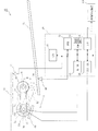
図2は、この発明の実施形態に係る給紙装置の概略図である。給紙装置10は、原稿載置台11、制御部20、ピックアップローラ30、センサ40、捌きローラ50、モータ51、アーム52、駆動ギア53、伝達ギア54、従動ギア55、摩擦板60、カバー70を備えている。
FIG. 2 is a schematic view of a paper feeding device according to an embodiment of the present invention. The
原稿載置台11は、この発明の載置台であり、上面にシートとしての原稿が載置される。原稿載置台11上の原稿は、矢印X方向の繰り出し方向に繰り出される。原稿載置台11から繰り出された原稿は、図示しない原稿搬送路内を搬送される。 The document placing table 11 is a placing table of the present invention, and a document as a sheet is placed on the upper surface. The document on the document table 11 is fed in the feeding direction indicated by the arrow X. The document fed from the document table 11 is conveyed in a document conveyance path (not shown).
ピックアップローラ30は、一端を捌きローラ50の回転軸50Aに軸支されたアーム52の他端に軸支されている。ピックアップローラ30は、アーム52とともに回転軸50A回りに揺動自在にされている。ピックアップローラ30は、図中2点差線で示す原稿載置台11の上面に当接する下限位置と、図中実線で示す原稿載置台11の上面から所定距離H1だけ離れた上限位置との間で昇降し、図中時計方向に回転して原稿載置台11から原稿を繰り出す。
The
捌きローラ50は、周面を摩擦板60に当接させて回転自在に配置されている。捌きローラ50の回転軸50Aには、モータ51の回転軸が同軸に固定されている。捌きローラ50は、図中時計方向に回転し、ピックアップローラ30によって繰り出された原稿のうち、最上部の1枚の原稿のみを摩擦板60との間に通過させる。
The
モータ51は、正逆両方向に駆動される。モータ51の回転軸には駆動ギア53が取り付けられており、モータ51の回転軸の回転は、駆動ギア53及び伝達ギア54を介してピックアップローラ30の回転軸30Aに固定された従動ギア55に伝達される。また、モータ51の回転軸の回転は、クラッチ56を介してアーム52に伝達される。伝達ギア54は、アーム52に軸支されている。
The
モータ51を正転方向に駆動すると、アーム52が図中時計方向に回転してピックアップローラ30が下降するとともに、ピックアップローラ30が図中時計方向に回転する。モータ51を逆転方向に駆動すると、アーム52が図中反時計方向に回転してピックアップローラ30が上昇するとともに、ピックアップローラ30が図中反時計方向に回転する。アーム52は、クラッチ56の選択的な駆動によってピックアップローラ30が距離H1を移動する回転量を最大値として回転する。モータ51が駆動されていない状態では、アーム52の回転位置は、図示しないラッチ機構によって保持される。
When the
モータ51、アーム52、駆動ギア53、伝達ギア54、従動ギア55、クラッチ56がこの発明の駆動機構に相当する。
The
センサ40は、この発明の検出手段であり、矢印X方向における原稿載置台11の下流側端部で、原稿の有無を検出する。
The
カバー70は、矢印X方向におけるピックアップローラ30及び捌きローラ50を含む下流側の上面を開閉自在に被覆する。カバー70の開閉状態は、センサ71によって検出される。
The
制御部20は、ROM22及びRAM23を備えたCPU21に、モータドライバ24、クラッチドライバ25、センサ40,71及びインタフェース26を接続して構成されている。CPU21は、ROM22に予め書き込まれたプログラムに従って、センサ40,71の検出信号等に応じてモータドライバ24及びクラッチドライバ25に駆動データを供給する。
The
このとき、CPU21は、RAM23のメモリエリアMA1〜3に割り当てられたフラグF1、フラグF2及びタイマT1の内容を参照する。フラグF1は、電源投入後及びジャム処理後にイニシャル処理を行ったか否かの状態を記憶する。フラグF2は、この発明の記憶手段であり、ピックアップローラ30を上限位置まで上昇させるためのモータ51の駆動を行ったか否かの状態を記憶する。タイマT1は、原稿載置台11から原稿が取り除かれた時に起動して所定時間を経時する。
At this time, the
モータドライバ24及びクラッチドライバ25は、駆動データに基づいてモータ51及びクラッチ56を駆動する。
The
CPU21は、インタフェース26を介して、画像形成装置100の制御部とデータの入出力を行う。画像形成装置100がスキャナユニット112で原稿の画像の読取処理を行う場合に、画像形成装置100の制御部からCPU21に給紙要求が出力される。スキャナユニット112が制御部を備える場合には、給紙要求を出力するスキャナユニット112の制御部をCPU21に接続する。
The
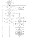
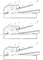
図3は、上記給紙装置の制御部の処理手順を示すフローチャートである。図4及び図5は、給紙装置の動作状態を示す概略の側面断面図である。 FIG. 3 is a flowchart illustrating a processing procedure of the control unit of the sheet feeding device. 4 and 5 are schematic side cross-sectional views showing the operating state of the sheet feeding device.
制御部20のCPU21は、給紙装置10に電源が投入されると、RAM23内のフラグF1、フラグF2及びタイマT1をリセットし(S1)、カバー70が開放されているか否かを判別する(S2)。
When the power is supplied to the
カバー70が閉鎖されている場合には、CPU21は、原稿のジャムを発生しているか否かの判別を行い(S3)、ジャムを発生していない場合には、原稿載置台11に原稿が載置されているか否かの判別を行う(S4)。原稿載置台11に原稿が載置されていない場合には、CPU21は、タイマT1によって所定時間の計時を開始する(S5)。
If the
カバー70の閉鎖状態が維持されたまま、原稿載置台11に原稿が載置されることなくタイマT1が所定時間を計時すると(S6)、CPU21は、フラグF1がリセット状態か否かを判別する(S7)。
When the timer T1 measures a predetermined time without placing a document on the document placing table 11 while the
フラグF1は、ピックアップローラ30を一旦下限位置まで下降させた後に距離H1だけ上昇させる昇降動作が実行されたか否かの状態、即ちピックアップローラ30が上限位置にあるか否かの状態を記憶する。CPU21は、フラグF1がセット状態であればピックアップローラ30が上限位置にあると判断し、フラグF1がリセット状態であればピックアップローラ30が上限位置にないと判断する。
The flag F1 stores the state of whether or not the lifting / lowering operation for raising the distance by H1 after the
フラグF1がリセット状態であり、ピックアップローラ30が上限位置にないと判断した場合、CPU21は、初期動作として昇降動作を実行する(S7)。このとき、CPU21は、モータ51を所定量正転させた後に所定量逆転させる駆動データをモータドライバ24に供給する。
When it is determined that the flag F1 is in the reset state and the
ステップS2〜S8の処理により、CPU21は、給紙装置10に電源が投入された際に原稿載置台11に原稿がない場合、図4(A)〜(C)に示すように、ピックアップローラ30を上限位置に停止させ、原稿載置台11への原稿の載置を待機する。
As a result of the processing in steps S2 to S8, when there is no document on the document table 11 when the power is supplied to the
センサ40が原稿載置台11に原稿が載置された状態を検出すると、CPU21は、フラグF1の状態を判別する(S9)。CPU21は、ピックアップローラ30が上限位置にあってフラグF1がセットされている場合には、給紙要求が入力されたか否かを判別する(S13)。
When the
CPU21は、給紙装置10に電源が投入された際に原稿載置台11に原稿がある場合には、CPU21は、ステップS2〜S4,S9〜S13の処理により、図5(A)及び(B)に示すように、モータ51を逆転駆動し、所定量H2だけピックアップローラ30を上昇させる。これによって、原稿載置台11に対する原稿の出し入れを容易に行うことができる。この状態で、CPU21は、ステップS2〜S4,S9,S13の処理を繰り返し、給紙要求の入力を待機する。
If there is a document on the document table 11 when the power is supplied to the
給紙要求が入力されると、CPU21は、モータ51を正転させて給紙動作を行う(S14)。モータ51の正転により、ピックアップローラ30が回転しつつ下降し、原稿載置台11に載置されている原稿のうち最上部の原稿の上面に当接する。最上部の原稿が矢印X方向に繰り出される。CPU21は、原稿の先端部が少なくとも原稿搬送路15内の矢印X方向における捌きローラ50の下流側に配置されている搬送ローラ13(図4参照。)に達するまで、モータ51の正転方向の駆動を継続する。CPU21は、給紙動作を終了すると、フラグF1およびフラグF2をリセットしてステップS2に戻る(S15)。
When a paper feed request is input, the
CPU21は、原稿載置台11に載置されている原稿の給紙要求が入力されている状態で、ステップS2〜S4,S9,S13〜S15の処理を繰り返し行い、画像形成装置100における処理に必要な枚数の原稿を給紙する。
The
原稿の給紙動作中にジャムが発生すると、CPU21は、モータ51の駆動を停止する。ジャムの発生は、原稿搬送路15内に配置されたセンサ16,17の検出信号に基づいて検出される。ジャム解除作業は、カバー70を開放して行われる。
If a jam occurs during the document feeding operation, the
CPU21は、センサ71がカバー70の開放状態を検出すると、フラグF1及びフラグF2をリセットし(S16)、カバー70の閉鎖及びジャム解除作業の完了を待機する(S2,S3)。
When the
ジャム処理が完了してカバー70が閉鎖されると、CPU21は、原稿載置台11上の原稿の有無に応じて、原稿がない場合には昇降動作を実行し、原稿がある場合には所定量H2だけピックアップローラ30を上昇させる。
When the jam processing is completed and the
この所定量H2は、距離H1に対して十分に小さい値、例えば、原稿載置台11における載置可能な最大枚数の原稿が載置された時の最上部の原稿の上面の位置と上限位置にあるピックアップローラ30の周面の最下点との長さ以下の値とする。これによって、ピックアップローラ30が比較的高い位置に位置している場合でも、ピックアップローラ30をカバー70等の他の部材に衝突させることなく、原稿載置台11へ原稿を載置する作業や原稿を積み増しする作業を容易に行うことができる。このために、ピックアップローラ30の位置を検出する手段を備える必要がなく、装置の小型化及びコストダウンを実現できる。
The predetermined amount H2 is a value sufficiently small with respect to the distance H1, for example, the upper surface position and upper limit position of the uppermost document when the maximum number of documents that can be placed on the document table 11 is placed. The value is equal to or less than the length from the lowest point of the circumferential surface of a
また、原稿載置台11に載置されていた原稿が取り除かれた場合、CPU21は、タイマT1が計時する所定時間が経過するまでピックアップローラ30を昇降させない。このため、作業者が原稿載置台11に一旦載置した複数枚の原稿を出し入れして整合させている間にピックアップローラ30が下限位置まで下降することがなく、原稿載置台11への原稿の載置作業を確実に行うことができる。
Further, when the document placed on the document placing table 11 is removed, the
なお、上記の例では、画像形成装置100のスキャナユニット112に搬送すべき原稿を給紙する給紙装置10を例に挙げて説明したが、記録用紙等の他のシートを給紙する給紙装置にもこの発明を同様に適用することができる。また、給紙装置10をスキャナユニット113に一体的に備えることもできる。
In the above example, the
上述の実施形態の説明は、すべての点で例示であって、制限的なものではないと考えられるべきである。本発明の範囲は、上述の実施形態ではなく、特許請求の範囲によって示される。さらに、本発明の範囲には、特許請求の範囲と均等の意味および範囲内でのすべての変更が含まれることが意図される。 The above description of the embodiment is to be considered in all respects as illustrative and not restrictive. The scope of the present invention is shown not by the above embodiments but by the claims. Furthermore, the scope of the present invention is intended to include all modifications within the meaning and scope equivalent to the scope of the claims.
10−給紙装置
11−原稿載置台(載置台)
20−制御部)
30−ピックアップローラ
40−センサ(検出手段)
51−モータ(駆動機構)
52−アーム(駆動機構)
53−駆動ギア(駆動機構)
54−伝達ギア(駆動機構)
55−従動ギア(駆動機構)
56−クラッチ(駆動機構)
70−カバー
100−画像形成装置
112−スキャナユニット(原稿読取装置)
10-paper feeder 11-document placing table (mounting table)
20-control unit)
30-pickup roller 40-sensor (detection means)
51-motor (drive mechanism)
52-arm (drive mechanism)
53-Drive gear (drive mechanism)
54-Transmission gear (drive mechanism)
55-Driven gear (drive mechanism)
56-clutch (drive mechanism)
70-cover 100-image forming apparatus 112-scanner unit (original reading apparatus)
Claims (5)
前記載置台におけるシートの有無を検出する検出手段と、
前記載置台の上面に当接する下限位置と前記載置台の上面から所定距離離れた上限位置との間で昇降自在に支持され、回転によって前記載置台からシートを繰り出すピックアップローラと、
前記ピックアップローラを昇降させる駆動機構と、
電源投入時及びジャム解除後に実行すべき初期動作時に、前記駆動機構を介して、前記検出手段がシートを検出していない場合には前記ピックアップローラを前記下限位置に達するまで下降させた後に前記上限位置まで上昇させる第1の制御を行い、前記検出手段がシートを検出している場合には前記ピックアップローラを前記所定距離よりも短い距離だけ上昇させる第2の制御を行う制御部と、備えた給紙装置。 A mounting table on which the sheet is mounted;
Detecting means for detecting the presence or absence of a sheet in the mounting table;
A pickup roller that is supported so as to be movable up and down between a lower limit position that contacts the upper surface of the mounting table and an upper limit position that is a predetermined distance away from the upper surface of the mounting table, and that feeds the sheet from the mounting table by rotation,
A drive mechanism for raising and lowering the pickup roller;
If the detection means does not detect a sheet through the drive mechanism at the time of power-on and initial operation to be performed after jam release, the upper limit is set after the pickup roller is lowered until reaching the lower limit position. A control unit that performs first control to raise the position to a position and performs second control to raise the pickup roller by a distance shorter than the predetermined distance when the detection unit detects a sheet; Paper feeder.
前記制御部は、前記初期動作時に、前記モータの回転動作を制御する請求項1に記載の給紙装置。 The drive mechanism includes a motor that rotates in both forward and reverse directions, and rotates the pickup roller in the sheet feeding direction during forward rotation of the motor and lowers the sheet toward the upper surface of the mounting table. Raise the pickup roller away from the top surface of the mounting table,
The sheet feeding device according to claim 1, wherein the control unit controls a rotation operation of the motor during the initial operation.
Priority Applications (3)
| Application Number | Priority Date | Filing Date | Title |
|---|---|---|---|
| JP2008224556A JP4558822B2 (en) | 2008-09-02 | 2008-09-02 | Paper feeding device and document reading device |
| US12/542,788 US8016284B2 (en) | 2008-09-02 | 2009-08-18 | Sheet feeding device and document reading device |
| CN2009101717595A CN101665192B (en) | 2008-09-02 | 2009-09-02 | Sheet feeding device and document reading device |
Applications Claiming Priority (1)
| Application Number | Priority Date | Filing Date | Title |
|---|---|---|---|
| JP2008224556A JP4558822B2 (en) | 2008-09-02 | 2008-09-02 | Paper feeding device and document reading device |
Publications (2)
| Publication Number | Publication Date |
|---|---|
| JP2010058884A true JP2010058884A (en) | 2010-03-18 |
| JP4558822B2 JP4558822B2 (en) | 2010-10-06 |
Family
ID=41724150
Family Applications (1)
| Application Number | Title | Priority Date | Filing Date |
|---|---|---|---|
| JP2008224556A Active JP4558822B2 (en) | 2008-09-02 | 2008-09-02 | Paper feeding device and document reading device |
Country Status (3)
| Country | Link |
|---|---|
| US (1) | US8016284B2 (en) |
| JP (1) | JP4558822B2 (en) |
| CN (1) | CN101665192B (en) |
Cited By (2)
| Publication number | Priority date | Publication date | Assignee | Title |
|---|---|---|---|---|
| JP2014015279A (en) * | 2012-07-06 | 2014-01-30 | Canon Inc | Document conveyance apparatus and method for initializing document conveyance apparatus |
| KR101421076B1 (en) * | 2011-01-31 | 2014-07-18 | 교세라 도큐멘트 솔루션즈 가부시키가이샤 | Sheet feeding apparatus with pick up roller and image forming apparatus |
Families Citing this family (3)
| Publication number | Priority date | Publication date | Assignee | Title |
|---|---|---|---|---|
| JP6482156B2 (en) * | 2014-05-21 | 2019-03-13 | キヤノンファインテックニスカ株式会社 | Paper feeder |
| CN104709738A (en) * | 2015-01-19 | 2015-06-17 | 哈尔滨市君诚信电子有限公司 | Paper separating mechanism of paper feed bin |
| CN107643666A (en) * | 2017-10-24 | 2018-01-30 | 贵州云侠科技有限公司 | Multifunctional colour laser printer |
Citations (6)
| Publication number | Priority date | Publication date | Assignee | Title |
|---|---|---|---|---|
| JPH03124647A (en) * | 1988-10-14 | 1991-05-28 | Nisca Corp | Feeder |
| JPH0543090A (en) * | 1991-08-21 | 1993-02-23 | Nisca Corp | Sheet feeding device |
| JP2002326726A (en) * | 2001-05-07 | 2002-11-12 | Fuji Xerox Co Ltd | Sheet feeder |
| JP2005277533A (en) * | 2004-03-23 | 2005-10-06 | Murata Mach Ltd | Image scanner |
| JP2006103840A (en) * | 2004-10-01 | 2006-04-20 | Canon Finetech Inc | Sheet feeding device and image forming device equipped with it |
| JP2006111373A (en) * | 2004-10-12 | 2006-04-27 | Canon Finetech Inc | Sheet carrying device, and image reading device |
Family Cites Families (10)
| Publication number | Priority date | Publication date | Assignee | Title |
|---|---|---|---|---|
| JPH06144658A (en) * | 1992-11-11 | 1994-05-24 | Ricoh Co Ltd | Automatic document feeder |
| JPH07323935A (en) * | 1994-04-07 | 1995-12-12 | Fujitsu Ltd | Paper feeder for image reader, image reader with paper feeder, and paper feeder |
| JP3490213B2 (en) * | 1996-04-11 | 2004-01-26 | 株式会社リコー | Paper transport device |
| JP3636078B2 (en) | 2001-01-24 | 2005-04-06 | 村田機械株式会社 | Paper feeder |
| JP2002002972A (en) | 2001-05-22 | 2002-01-09 | Canon Inc | Sheet feeding device |
| JP3661783B2 (en) * | 2001-10-15 | 2005-06-22 | ニスカ株式会社 | Document feeder and document feed control method |
| CN100368207C (en) * | 2002-08-20 | 2008-02-13 | 夏普株式会社 | Paper-delivering device and image forming device with the paper-delivering device |
| JP4480355B2 (en) * | 2003-06-27 | 2010-06-16 | シャープ株式会社 | Sheet feeding device, image forming device |
| JP2010064805A (en) * | 2008-09-08 | 2010-03-25 | Kyocera Mita Corp | Paper feeder and image forming device having the same |
| JP2010083600A (en) * | 2008-09-29 | 2010-04-15 | Ricoh Co Ltd | Document carrying device, image reader, control method of document carrying device, control program and recording medium |
-
2008
- 2008-09-02 JP JP2008224556A patent/JP4558822B2/en active Active
-
2009
- 2009-08-18 US US12/542,788 patent/US8016284B2/en not_active Expired - Fee Related
- 2009-09-02 CN CN2009101717595A patent/CN101665192B/en active Active
Patent Citations (6)
| Publication number | Priority date | Publication date | Assignee | Title |
|---|---|---|---|---|
| JPH03124647A (en) * | 1988-10-14 | 1991-05-28 | Nisca Corp | Feeder |
| JPH0543090A (en) * | 1991-08-21 | 1993-02-23 | Nisca Corp | Sheet feeding device |
| JP2002326726A (en) * | 2001-05-07 | 2002-11-12 | Fuji Xerox Co Ltd | Sheet feeder |
| JP2005277533A (en) * | 2004-03-23 | 2005-10-06 | Murata Mach Ltd | Image scanner |
| JP2006103840A (en) * | 2004-10-01 | 2006-04-20 | Canon Finetech Inc | Sheet feeding device and image forming device equipped with it |
| JP2006111373A (en) * | 2004-10-12 | 2006-04-27 | Canon Finetech Inc | Sheet carrying device, and image reading device |
Cited By (2)
| Publication number | Priority date | Publication date | Assignee | Title |
|---|---|---|---|---|
| KR101421076B1 (en) * | 2011-01-31 | 2014-07-18 | 교세라 도큐멘트 솔루션즈 가부시키가이샤 | Sheet feeding apparatus with pick up roller and image forming apparatus |
| JP2014015279A (en) * | 2012-07-06 | 2014-01-30 | Canon Inc | Document conveyance apparatus and method for initializing document conveyance apparatus |
Also Published As
| Publication number | Publication date |
|---|---|
| US20100052249A1 (en) | 2010-03-04 |
| CN101665192B (en) | 2011-11-30 |
| CN101665192A (en) | 2010-03-10 |
| US8016284B2 (en) | 2011-09-13 |
| JP4558822B2 (en) | 2010-10-06 |
Similar Documents
| Publication | Publication Date | Title |
|---|---|---|
| JP5495681B2 (en) | Sheet feeding apparatus, image reading apparatus, and image forming apparatus | |
| JP4558822B2 (en) | Paper feeding device and document reading device | |
| JP3906885B2 (en) | Sheet supply apparatus, image forming apparatus, and sheet supply method | |
| JP6082290B2 (en) | Medium supply device | |
| JP5965341B2 (en) | Medium supply device | |
| JP6676298B2 (en) | Image reading device and image forming device | |
| JP5791352B2 (en) | Paper feeding device and image forming apparatus | |
| JP2006016093A (en) | Original feeder | |
| JP3190390B2 (en) | Drive control method for automatic paper feeder | |
| JP2005225643A (en) | Sheet feeder and image forming device | |
| JP6657989B2 (en) | Automatic document reading device, image forming device | |
| JP2006306564A (en) | Sheet handling device, and image forming device | |
| JP4031665B2 (en) | Paper feeding device and printing device | |
| JP2008254896A (en) | Sheet feeder, document feeder and image forming device | |
| JP2016137979A (en) | Feeding device, control method of the same, and program | |
| JP4498063B2 (en) | Image forming apparatus | |
| JP4852489B2 (en) | Paper feeder and automatic document feeder | |
| JP2009196780A (en) | Recording medium feeder and image forming device | |
| JP2022115275A (en) | Paper feeding device, image reading device, image forming device | |
| JP2017019606A (en) | Feeding device, control method therefor, image reading device, image forming device, and program | |
| JP2006327777A (en) | Paper feeding device | |
| US9459581B2 (en) | Image forming apparatus | |
| JP2003246471A (en) | Paper feeder and image forming device | |
| JP2913432B2 (en) | Document fall prevention device for image forming apparatus | |
| JP2004262606A (en) | Sheet feeder and image forming apparatus using the same |
Legal Events
| Date | Code | Title | Description |
|---|---|---|---|
| A977 | Report on retrieval |
Free format text: JAPANESE INTERMEDIATE CODE: A971007 Effective date: 20100615 |
|
| TRDD | Decision of grant or rejection written | ||
| A01 | Written decision to grant a patent or to grant a registration (utility model) |
Free format text: JAPANESE INTERMEDIATE CODE: A01 Effective date: 20100622 |
|
| A01 | Written decision to grant a patent or to grant a registration (utility model) |
Free format text: JAPANESE INTERMEDIATE CODE: A01 |
|
| A61 | First payment of annual fees (during grant procedure) |
Free format text: JAPANESE INTERMEDIATE CODE: A61 Effective date: 20100721 |
|
| R150 | Certificate of patent or registration of utility model |
Free format text: JAPANESE INTERMEDIATE CODE: R150 Ref document number: 4558822 Country of ref document: JP Free format text: JAPANESE INTERMEDIATE CODE: R150 |
|
| FPAY | Renewal fee payment (event date is renewal date of database) |
Free format text: PAYMENT UNTIL: 20130730 Year of fee payment: 3 |