JP2010063566A - Compact case - Google Patents

Compact case Download PDF

Info

Publication number
JP2010063566A
JP2010063566A JP2008231683A JP2008231683A JP2010063566A JP 2010063566 A JP2010063566 A JP 2010063566A JP 2008231683 A JP2008231683 A JP 2008231683A JP 2008231683 A JP2008231683 A JP 2008231683A JP 2010063566 A JP2010063566 A JP 2010063566A
Authority
JP
Japan
Prior art keywords
cosmetic dish
wall
lid
dish
container body
Prior art date
Legal status (The legal status is an assumption and is not a legal conclusion. Google has not performed a legal analysis and makes no representation as to the accuracy of the status listed.)
Granted
Application number
JP2008231683A
Other languages
Japanese (ja)
Other versions
JP5260199B2 (en
Inventor
Yuzo Yoshida
雄三 吉田
Yasuko Nakajima
靖子 中島
Current Assignee (The listed assignees may be inaccurate. Google has not performed a legal analysis and makes no representation or warranty as to the accuracy of the list.)
Yoshida Industry Co Ltd
Original Assignee
Yoshida Industry Co Ltd
Priority date (The priority date is an assumption and is not a legal conclusion. Google has not performed a legal analysis and makes no representation as to the accuracy of the date listed.)
Filing date
Publication date
Application filed by Yoshida Industry Co Ltd filed Critical Yoshida Industry Co Ltd
Priority to JP2008231683A priority Critical patent/JP5260199B2/en
Priority to US12/554,071 priority patent/US8302614B2/en
Priority to FR0956091A priority patent/FR2935592B1/en
Publication of JP2010063566A publication Critical patent/JP2010063566A/en
Application granted granted Critical
Publication of JP5260199B2 publication Critical patent/JP5260199B2/en
Expired - Fee Related legal-status Critical Current
Anticipated expiration legal-status Critical

Links

Images

Classifications

    • AHUMAN NECESSITIES
    • A45HAND OR TRAVELLING ARTICLES
    • A45DHAIRDRESSING OR SHAVING EQUIPMENT; EQUIPMENT FOR COSMETICS OR COSMETIC TREATMENTS, e.g. FOR MANICURING OR PEDICURING
    • A45D33/00Containers or accessories specially adapted for handling powdery toiletry or cosmetic substances
    • A45D33/006Vanity boxes or cases, compacts, i.e. containing a powder receptacle and a puff or applicator
    • A45D33/008Vanity boxes or cases, compacts, i.e. containing a powder receptacle and a puff or applicator comprising a mirror
    • AHUMAN NECESSITIES
    • A45HAND OR TRAVELLING ARTICLES
    • A45DHAIRDRESSING OR SHAVING EQUIPMENT; EQUIPMENT FOR COSMETICS OR COSMETIC TREATMENTS, e.g. FOR MANICURING OR PEDICURING
    • A45D40/00Casings or accessories specially adapted for storing or handling solid or pasty toiletry or cosmetic substances, e.g. shaving soaps or lipsticks
    • A45D40/22Casings characterised by a hinged cover
    • A45D40/222Means for closing the lid

Landscapes

  • Closures For Containers (AREA)

Abstract

<P>PROBLEM TO BE SOLVED: To provide a compact case with improved assembly and producibility, and stability in opening and closing. <P>SOLUTION: The compact case comprises: a case body 2 where a lid 3 is rotatably connected to a rear wall 21; a pair of slits 27 formed therein at a front side part or a rear side part of a bottom wall 25 along respective side walls 23, 24 of the body 2; a pair of elastically deformable pushing walls 29 formed in the respective side walls facing the respective slits; a cosmetic dish 4 that fits between the respective side walls and is slidable in a longitudinal direction of the body; a hook part engaging the cosmetic dish and the lid so as to hold the lid at a closed position and to release the engagement through sliding movement of the cosmetic dish; projections 26 integrally formed with the pushing walls facing the cosmetic dish; and a slope part 42 integrally provided to the cosmetic dish facing the projection, and squeezing the pushing wall causes the projection to move slidably to make the cosmetic dish 4 slide forward or rearward. <P>COPYRIGHT: (C)2010,JPO&INPIT

Description

本発明は、左右側壁を外方から押圧操作することで、容器本体と蓋体との係合状態を解除可能なコンパクト容器に関する。   The present invention relates to a compact container that can release the engaged state between a container body and a lid by pressing the left and right side walls from the outside.

従来、容器本体の両側壁の外方からの押圧操作で、蓋体を開放するコンパクト容器として、例えば特許文献1が知られている。   Conventionally, for example, Patent Document 1 is known as a compact container in which a lid is opened by a pressing operation from the outside of both side walls of a container body.

特許文献1のコンパクト容器は、容器本体の底壁部に、側壁部の長さ方向に沿って形成されるスリットにより、側壁部が容器本体内方へ押圧操作可能に弾性変形される。他方、容器本体には、その内部に中皿が収納され、中皿で覆われた底壁部には溝部が形成され、溝部には薄板状のスライドピースが設けられる。スライドピースは、弾性変形された側壁部によって押圧操作されることで、溝部内でスライド移動される。そして、スライドピースの前端側に形成され、スライドピースのスライド移動に応じて前後方向に移動する係合部が、蓋体に設けられる突起に係脱自在に係合されて、容器本体と蓋体とを係合する。
特開2007−289290号公報
The compact container of Patent Document 1 is elastically deformed so that the side wall portion can be pressed inwardly into the container body by a slit formed in the bottom wall portion of the container body along the length direction of the side wall portion. On the other hand, the container main body accommodates an inner dish therein, a groove portion is formed in the bottom wall portion covered with the inner dish, and a thin plate-like slide piece is provided in the groove portion. The slide piece is slid and moved in the groove by being pressed by the elastically deformed side wall. And the engaging part which is formed in the front end side of a slide piece, and moves to the front-back direction according to the slide movement of a slide piece is engaged with the protrusion provided in a lid so that it can be freely engaged and disengaged, and a container main body and a lid And engage.
JP 2007-289290 A

ところで、背景技術にあっては、蓋体と容器本体とを係脱自在に係合するために、容器本体と中皿としての化粧料皿との間に、その前端部に係合部を形成したスライドピースが、別部品として組みこまれている。これにより、コンパクト容器の部品点数が多くなり、操作の際に安定感がないという課題があった。また、製造が繁雑になるという課題もあった。   By the way, in the background art, in order to detachably engage the lid and the container main body, an engaging portion is formed at the front end portion between the container main body and the cosmetic dish as the middle dish. The slide piece is assembled as a separate part. Thereby, the number of parts of a compact container increases and there existed a subject that there was no sense of stability in operation. In addition, there is a problem that manufacturing is complicated.

本発明は上記従来の課題に鑑みて創案されたものであって、左右側壁を押圧操作することで、容器本体と蓋体との係合状態を解除可能なコンパクト容器において、開閉時の操作性を安定させ、組み付け性を良好にし、生産性も良好なコンパクト容器を提供することを目的とする。   The present invention was devised in view of the above-described conventional problems, and in a compact container in which the engagement state between the container body and the lid can be released by pressing the left and right side walls, the operability at the time of opening and closing is provided. The purpose of this invention is to provide a compact container that stabilizes the assembly, improves the assemblability, and has good productivity.

本発明にかかるコンパクト容器は、蓋体が後壁に回動自在に連結された容器本体と、該容器本体の左右側壁に沿って、その前方部若しくは後方部の底壁に形成される一対の短尺スリットと、これら一対の短尺スリットに面して、該左右側壁に弾性変形可能に形成される一対の押圧壁と、該容器本体内に、左右側壁の間で前後方向スライド自在に嵌着される化粧料皿と、該化粧料皿と該蓋体の間に、該化粧料皿と該蓋体とを係脱自在に係合して該容器本体の閉蓋状態を保持し、該化粧料皿のスライド移動によって、その係合を解除するフック部と、該押圧壁若しくは該化粧料皿のいずれか一方に、一体形成される突起部と、該突起部に面して、該化粧料皿若しくは該押圧壁に一体形成され、該押圧壁の押圧操作で、該突起部を摺動自在に摺動させて該化粧料皿を前方若しくは後方のいずれか一方にスライド移動させる傾斜部とを有することを特徴とする。   A compact container according to the present invention includes a container body whose lid is rotatably connected to a rear wall, and a pair of bottom walls formed on the front or rear part along the left and right side walls of the container body. A short slit, a pair of pressing walls facing the pair of short slits and elastically deformable on the left and right side walls, and a slidable back and forth between the left and right side walls are fitted in the container body. A cosmetic dish, and between the cosmetic dish and the lid body, the cosmetic dish and the lid body are detachably engaged to keep the container body closed, A hook part that releases the engagement by sliding movement of the dish, a protruding part integrally formed on either the pressing wall or the cosmetic dish, and facing the protruding part, the cosmetic dish Alternatively, it is formed integrally with the pressing wall, and the protruding portion is slidably slid by the pressing operation of the pressing wall. And having an inclined portion for sliding in either the cosmetic dish forward or backward of Te.

前記突起部は複数形成されるとともに、該突起部に対応させて、前記傾斜部も複数形成されることを特徴とする。   A plurality of the protruding portions are formed, and a plurality of the inclined portions are formed corresponding to the protruding portions.

前記化粧料皿と、前記容器本体の前記後壁および前記前壁のいずれかとの間には隙間が形成され、該隙間内には、前方若しくは後方へスライド移動した該化粧料皿により弾性変形され、その弾性復原力によって該化粧料皿を元の位置へ押し戻す弾性変形部材が設けられることを特徴とする。   A gap is formed between the cosmetic dish and one of the rear wall and the front wall of the container body, and the gap is elastically deformed by the cosmetic dish slid forward or backward in the gap. The elastic deformation member is provided to push the cosmetic dish back to the original position by the elastic restoring force.

前記蓋体には、その前端に前記容器本体の前記前壁全体をその前方から覆う垂下前壁部が形成されることを特徴とする。   The lid body is characterized in that a drooping front wall portion that covers the entire front wall of the container body from the front is formed at the front end thereof.

本発明にかかるコンパクト容器にあっては、左右側壁を押圧操作することで、容器本体と蓋体との係合状態を解除可能なコンパクト容器において、組み付け性を良好にし、生産性も良好にするとともに、開閉時の操作性を安定させることができる。   In the compact container according to the present invention, in the compact container in which the engagement state between the container main body and the lid body can be released by pressing the left and right side walls, the assembling property is improved and the productivity is also improved. At the same time, the operability during opening and closing can be stabilized.

また、容器本体の側壁と化粧料皿の間を巾を狭く形成することができ、意匠性を良好にすることができる。   Moreover, the width | variety can be narrowly formed between the side wall of a container main body, and a cosmetics plate, and designability can be made favorable.

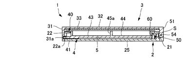
以下に、本発明にかかるコンパクト容器の好適な一実施形態を、添付図面を参照して詳細に説明する。本実施形態にかかるコンパクト容器1は基本的には、図1〜図7に示すように、蓋体3が後壁21に回動自在に連結された容器本体2と、容器本体2の左右側壁23、24に沿って、その前方部若しくは後方部の底壁25に形成される一対の短尺スリット27と、これら一対の短尺スリット27に面して、左右側壁23、24に弾性変形可能に形成される一対の押圧壁29と、容器本体2内に、左右側壁23、24の間で前後方向スライド自在に嵌着される化粧料皿4と、化粧料皿4と蓋体3の間に、化粧料皿4と蓋体3とを係脱自在に係合して容器本体2の閉蓋状態を保持し、化粧料皿4のスライド移動によって、その係合を解除するフック部と、化粧料皿4に面して、押圧壁29若しくは化粧料皿4のいずれか一方に一体形成される突起部26と、突起部26に面して化粧料皿4若しくは押圧壁29に一体形成され、押圧壁29の押圧操作で、突起部26を摺動自在に摺動させて化粧料皿4を前方若しくは後方のいずれか一方にスライド移動させる傾斜部42とを有する。   Hereinafter, a preferred embodiment of a compact container according to the present invention will be described in detail with reference to the accompanying drawings. As shown in FIGS. 1 to 7, the compact container 1 according to this embodiment basically includes a container body 2 in which a lid 3 is rotatably connected to a rear wall 21, and left and right side walls of the container body 2. A pair of short slits 27 formed in the bottom wall 25 at the front part or the rear part thereof along the lines 23 and 24, and facing the pair of short slits 27 so as to be elastically deformable on the left and right side walls 23 and 24. A pair of pressing walls 29, a cosmetic dish 4 that is slidably fitted between the left and right side walls 23, 24 in the container body 2, and between the cosmetic dish 4 and the lid 3, A cosmetic dish 4 and a lid 3 are detachably engaged to hold the container body 2 in a closed state, and the cosmetic dish 4 is slid to disengage the hook, and a cosmetic material. A protrusion that faces the dish 4 and is integrally formed on either the pressing wall 29 or the cosmetic dish 4 26, facing the protrusion 26, and integrally formed on the cosmetic dish 4 or the pressing wall 29. By pressing the pressing wall 29, the protrusion 26 is slidably slid to move the cosmetic dish 4 forward or And an inclined portion 42 that is slid and moved to either one of the rear sides.

化粧料皿4と、容器本体2の後壁21および前壁22のいずれかとの間には隙間Sが形成され、隙間S内には、前方若しくは後方へスライド移動した化粧料皿4により弾性変形され、その弾性復原力によって化粧料皿Sを元の位置へ押し戻す弾性変形部材が設けられる。   A gap S is formed between the cosmetic dish 4 and one of the rear wall 21 and the front wall 22 of the container body 2, and elastic deformation by the cosmetic dish 4 slidably moved forward or backward in the gap S. An elastic deformation member that pushes the cosmetic dish S back to the original position by the elastic restoring force is provided.

蓋体3には、その前端に容器本体2の前壁22全体をその前方から覆う垂下前壁部31が形成される。   A drooping front wall portion 31 that covers the entire front wall 22 of the container body 2 from the front is formed on the front end of the lid 3.

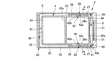
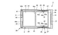
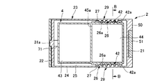
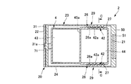
コンパクト容器1は主に、容器本体2と、蓋体3と、容器本体2内部に収納される化粧料皿4とからなる。容器本体2は合成樹脂材で形成される。容器本体2には、底壁25の周縁にその周方向に沿って、前壁22、後壁21、および左右の側壁23、24としての周側壁20が立設される。図示例にあっては、容器本体2は、前壁22および後壁21に対して、左右の側壁23、24の長さが長く、その平面外形輪郭が縦長の長方形状に形成される。容器本体2は縦長の長方形状に限られず、正方形などその他の形状であっても良い。周側壁部20の上端には、これより内方に延設される上縁部20aが形成される。   The compact container 1 mainly includes a container main body 2, a lid body 3, and a cosmetic dish 4 accommodated inside the container main body 2. The container body 2 is formed of a synthetic resin material. In the container body 2, a peripheral wall 20 as a front wall 22, a rear wall 21, and left and right side walls 23, 24 is erected along the circumferential direction of the bottom wall 25. In the illustrated example, the container body 2 is formed such that the left and right side walls 23, 24 are longer than the front wall 22 and the rear wall 21, and the planar outer contour thereof is formed in a vertically long rectangular shape. The container body 2 is not limited to a vertically long rectangular shape, and may be other shapes such as a square. At the upper end of the peripheral side wall portion 20, an upper edge portion 20a extending inward from the upper end portion is formed.

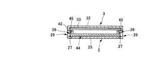
容器本体2には、蓋体3が回動自在に連結される。蓋体3は合成樹脂材で形成され、天板32の周縁にその周方向に沿って環状周壁部30が立設されて、容器本体2に合致する平面外形輪郭で皿状に形成される。蓋体3もまた縦長の長方形状に限られず、正方形などその他の形状であっても良い。天板32の裏面には、板状の鏡33が取り付けられる。蓋体3には、その前端に容器本体2の前壁22全体をその前方から覆う垂下前壁部31が形成される。   A lid 3 is rotatably connected to the container body 2. The lid 3 is formed of a synthetic resin material, and an annular peripheral wall portion 30 is erected along the circumferential direction on the periphery of the top plate 32, and is formed in a dish shape with a planar outer contour that matches the container body 2. The lid 3 is not limited to a vertically long rectangular shape, and may be other shapes such as a square. A plate-like mirror 33 is attached to the back surface of the top plate 32. A drooping front wall portion 31 that covers the entire front wall 22 of the container body 2 from the front is formed on the front end of the lid 3.

容器本体2の後壁21には、左右方向両端からそれぞれ後方へ突出させて、一対のヒンジ片50が形成される。ヒンジ片50の間には凹所53が形成される。また蓋体3の環状周壁部30には、これより凹所53内に垂下させて、ヒンジブロック51が形成される。そしてこれらヒンジブロック51とヒンジ片50との間には、それぞれヒンジピン54が挿入される。これによりヒンジ片50にヒンジブロック51が回動自在に連結されて、容器本体2を開閉すべく蓋体3が回動されるようになっている。   A pair of hinge pieces 50 are formed on the rear wall 21 of the container body 2 so as to protrude rearward from both ends in the left-right direction. A recess 53 is formed between the hinge pieces 50. A hinge block 51 is formed on the annular peripheral wall portion 30 of the lid 3 so as to hang from the recess 53. A hinge pin 54 is inserted between the hinge block 51 and the hinge piece 50. As a result, the hinge block 51 is pivotally connected to the hinge piece 50, and the lid 3 is rotated to open and close the container body 2.

容器本体2には、周側壁20に取り囲まれて化粧料皿収納部5が形成される。化粧料皿収納部5には化粧料皿4が収納される。化粧料皿4は合成樹脂材で皿状に形成される。化粧料皿4の周縁には、枠部45が形成される。枠部45の前後方向略中央には、枠部45の左右端部に亘って、化粧料皿4内部を前後に区画するしきり板45aが一体形成される。これにより、化粧料皿4には、しきり板45aの前後方向に化粧料やパフなどの化粧具を収納するための前皿部43、および後皿部44が形成される。枠部45は、その周縁部の外形が容器本体2の周側壁20の周端縁よりも小さく、かつ、周側壁20の上縁部20aに重ねあわされる程度の大きさに形成される。これにより、化粧料皿4を化粧料皿収納部5に収納した状態で、枠部45の周縁部の下面が、容器本体2の周側壁20の上縁部20aに当接するようになっている。   The container body 2 is surrounded by the peripheral side wall 20 to form a cosmetic dish storage portion 5. A cosmetic dish 4 is stored in the cosmetic dish storage unit 5. The cosmetic dish 4 is formed of a synthetic resin material in a dish shape. A frame 45 is formed on the periphery of the cosmetic dish 4. At substantially the center in the front-rear direction of the frame part 45, a cutting plate 45 a that divides the interior of the cosmetic dish 4 in the front-rear direction is integrally formed across the left and right ends of the frame part 45. Thereby, the front dish part 43 and the back dish part 44 for accommodating cosmetics, such as cosmetics and a puff, are formed in the cosmetic dish 4 in the front-rear direction of the threshold plate 45a. The frame portion 45 is formed in such a size that the outer shape of its peripheral edge portion is smaller than the peripheral end edge of the peripheral side wall 20 of the container body 2 and overlapped with the upper edge portion 20 a of the peripheral side wall 20. Thereby, the lower surface of the peripheral part of the frame part 45 contacts the upper edge part 20a of the peripheral side wall 20 of the container main body 2 in a state where the cosmetic dish 4 is stored in the cosmetic dish storage part 5. .

容器本体2には、その前壁22に、これを前後方向に貫通する孔部22aが形成される。化粧料皿4の前端部40には、前皿部43の前壁の外面から前方へ突出させて、孔部22aに挿抜自在に挿入される平板状のフック41が延設される。フック41は、化粧料皿4が後方へスライド移動した状態でも、孔部22aから脱落しない程度の長さに形成される。他方、蓋体3の垂下前壁部31には、容器本体2の前壁22に面する裏面に、孔部22aから突出したフック41と係脱自在に係合する凹溝状の係合部31aが形成される。化粧料皿収納部5内で化粧料皿4が前方へスライド移動すると、フック41が前壁22の孔部22aを介して係合部31aと係合する。フック41と係合部31aによりフック部が構成される。フック部が化粧料皿4と蓋体3との係合状態を維持することによって容器本体2の閉蓋状態が保持される。   The container body 2 is formed with a hole 22a penetrating through the front wall 22 in the front-rear direction. The front end 40 of the cosmetic dish 4 is extended with a flat hook 41 that protrudes forward from the outer surface of the front wall of the front dish 43 and is inserted into the hole 22a so as to be freely inserted and removed. The hook 41 is formed to a length that does not drop out of the hole 22a even when the cosmetic dish 4 slides backward. On the other hand, the hanging front wall portion 31 of the lid 3 has a concave groove-like engaging portion that is detachably engaged with the hook 41 protruding from the hole 22a on the back surface facing the front wall 22 of the container body 2. 31a is formed. When the cosmetic dish 4 slides forward in the cosmetic dish storage part 5, the hook 41 engages with the engaging part 31a through the hole 22a of the front wall 22. A hook part is comprised by the hook 41 and the engaging part 31a. When the hook portion maintains the engaged state between the cosmetic dish 4 and the lid 3, the closed state of the container body 2 is maintained.

容器本体2内には、左右側壁23、24と化粧料皿4とを前後方向スライド自在に嵌着する嵌着部が形成される。嵌着部は、容器本体2側に形成される第1嵌着部81と、化粧料皿4側に形成される第2嵌着部82とから構成される。図示例にあっては、第1嵌着部81は、容器本体2の後方部側に位置する、左右側壁23、24の上縁部20aで形成されている。他方、第2嵌着部82は、第1嵌着部81に面した後皿部43の左右側壁外面にそれぞれ形成される。第2嵌着部82は、後述する傾斜部42と枠部45とが隙間を挟んで形成されていることにより、これら傾斜部42と枠部45とで構成される。傾斜部42が、前後方向に適宜長さを有して形成されていることで、第2嵌着部82もまた前後方向へ適宜長さに形成される。化粧料皿4を装着するに際しては、容器本体2内に上方より化粧料皿4を挿入すると、傾斜部42が上縁部20aを乗り越えて、第1嵌着部41が第2嵌着部42に前後方向スライド自在に嵌着される。なお、本実施形態にあっては、前述したフック41が孔部22aに挿入されていることで、後方側だけでなく前方側においても、化粧料皿4の前後方向の移動が抑制される構成となっている。   In the container main body 2, fitting portions for fitting the left and right side walls 23 and 24 and the cosmetic dish 4 so as to be slidable in the front-rear direction are formed. The fitting portion includes a first fitting portion 81 formed on the container body 2 side and a second fitting portion 82 formed on the cosmetic dish 4 side. In the example of illustration, the 1st fitting part 81 is formed in the upper edge part 20a of the right-and-left side walls 23 and 24 located in the back part side of the container main body 2. FIG. On the other hand, the second fitting portions 82 are respectively formed on the left and right side wall outer surfaces of the rear dish portion 43 facing the first fitting portion 81. The 2nd fitting part 82 is comprised by these inclination part 42 and the frame part 45, when the inclination part 42 and the frame part 45 which are mentioned later are formed on both sides of the clearance gap. Since the inclined portion 42 is formed with an appropriate length in the front-rear direction, the second fitting portion 82 is also formed with an appropriate length in the front-rear direction. When the cosmetic dish 4 is mounted, when the cosmetic dish 4 is inserted into the container body 2 from above, the inclined part 42 gets over the upper edge part 20a, and the first fitting part 41 becomes the second fitting part 42. And is slidable in the front-rear direction. In the present embodiment, the hook 41 described above is inserted into the hole portion 22a, so that the movement of the cosmetic dish 4 in the front-rear direction is suppressed not only on the rear side but also on the front side. It has become.

容器本体2の底壁25には、左右側壁23、24に沿って一対の短尺スリット27が形成される。短尺スリット27は、容器本体2の後方部の底壁25に形成される。ここで容器本体2の後方部とは、容器本体2の前後方向略中央位置から後端までをいい、前方部もまた、容器本体2の前後方向略中央位置から前端にかけてをいう。図示例にあっては、短尺スリット27は、底壁25に、左右それぞれの側壁23、24よりもわずかに内側に位置させて形成される。短尺スリット27は、容器本体2の前後方向略中央から後壁21前方の適宜位置にかけて、底壁25を上下方向に真っ直ぐ貫通させた孔状に形成されている。これにより、短尺スリット27に対面する左右の側壁23、24には、弾性変形可能な押圧壁29が形成されることとなる。   A pair of short slits 27 are formed in the bottom wall 25 of the container body 2 along the left and right side walls 23 and 24. The short slit 27 is formed in the bottom wall 25 at the rear part of the container body 2. Here, the rear portion of the container main body 2 refers to the position from the substantially central position in the front-rear direction of the container main body 2 to the rear end, and the front portion also refers to the position from the substantially central position in the front-rear direction of the container main body 2 to the front end. In the illustrated example, the short slit 27 is formed in the bottom wall 25 so as to be positioned slightly inside the left and right side walls 23 and 24. The short slit 27 is formed in a hole shape that penetrates the bottom wall 25 straight up and down from the approximate center of the container body 2 in the front-rear direction to an appropriate position in front of the rear wall 21. Thus, elastically deformable pressing walls 29 are formed on the left and right side walls 23, 24 facing the short slit 27.

左右の押圧壁29には、一対の突起部26が一体形成される。他方、化粧料皿4には、突起部26に対面させて、これを摺動自在に摺動させることで、化粧料皿4を前方へスライド移動させる一対の傾斜部42が一体形成される。   A pair of protrusions 26 are integrally formed on the left and right pressing walls 29. On the other hand, the cosmetic dish 4 is integrally formed with a pair of inclined parts 42 that slide the cosmetic dish 4 forward by facing the protrusion 26 and sliding it slidably.

図示例にあっては、傾斜部42は、後皿部44の左右の側壁外面に、それぞれ1つずつ形成されている。傾斜部42は、後皿部44の側壁外面から後方へ向かうにしたがって次第に押圧壁29側に傾斜する傾斜面部42aと、傾斜面部42aの前方に、後皿部44の側壁外面から押圧壁29側へ前後方向適宜長さに突出形成される止め部42bとから構成される。   In the illustrated example, one inclined portion 42 is formed on each of the left and right side wall outer surfaces of the rear plate portion 44. The inclined portion 42 is inclined to the pressing wall 29 side gradually from the outer side wall of the rear plate portion 44 toward the rear, and in front of the inclined surface portion 42a, from the outer surface of the rear plate portion 44 to the pressing wall 29 side. It is comprised from the stop part 42b which protrudes and is formed in the front-back direction suitably length.

また、突起部26は、平断面が半円形状に化粧料皿4側に突出形成されている。突起部26には、前後方向中央から後方に向かって傾斜面26aが形成されている。傾斜面26aは、傾斜面部42aに当接しており、これより押圧壁29が内方へ弾性変形するに従い、傾斜面部42a上を前方に向けて摺動する。これにより、傾斜部42には、これを後方へ移動させる操作力が発生する。この操作力により傾斜部42を介して化粧料皿4は後方へスライド移動する。突起部26の前端が止め部42bに当接することで、化粧料皿4の後方へのスライド移動が終了する。   Moreover, the protrusion part 26 is protrudingly formed by the cosmetic dish 4 side so that a plane cross section may be semicircle shape. An inclined surface 26 a is formed on the protrusion 26 from the center in the front-rear direction toward the rear. The inclined surface 26a is in contact with the inclined surface portion 42a, and slides forward on the inclined surface portion 42a as the pressing wall 29 is elastically deformed inward. As a result, an operating force that moves the inclined portion 42 rearward is generated. With this operating force, the cosmetic dish 4 slides backward via the inclined portion 42. The sliding movement of the cosmetic dish 4 to the rear ends when the front end of the protrusion 26 comes into contact with the stopper 42b.

化粧料皿4と、後壁21および前壁22のいずれかとの間には、適宜な間隔の隙間Sが形成される。隙間S内には、スライド移動した化粧料皿4により弾性変形し、その弾性復原力によって、化粧料皿4を押圧操作前の元の位置へ押し戻す弾性変形部材が設けられる。   A gap S with an appropriate interval is formed between the cosmetic dish 4 and any one of the rear wall 21 and the front wall 22. In the gap S, there is provided an elastically deformable member that is elastically deformed by the cosmetic dish 4 that has been slid and that pushes the cosmetic dish 4 back to the original position before the pressing operation by its elastic restoring force.

図示例にあっては、後皿部44の後壁と、容器本体2の後壁21との間に隙間Sが形成されており、隙間S内に弾性変形部材としての板バネ60が配設されている。板バネは、金属製若しくは合成樹脂製で形成される。隙間S内の底壁25の左右両端には、板バネ60を容器本体2に固定する固定部61が形成される。板バネ60には、弾性変形自在な薄板状の湾曲部60aが形成され、その両端に固定部61に嵌着固定される留部60bが形成される。板バネ60は、留部60bを固定部61に固定して、湾曲部60aが前方に湾曲した状態で隙間S内に配設される。湾曲部60aの前端は、後皿部44に当接されている。押圧壁29の押圧操作により、化粧料皿4が後方へスライド移動すると、後皿部44に当接している湾曲部60aが、隙間S内で弾性変形する。そして、押圧壁29の押圧操作を解除すると、固定部61で容器本体2に固定された留部60bに反力をとって、湾曲部60aは隙間S内で弾性復原し、これによって、化粧料皿4を元の位置まで前方へスライド移動させる。   In the illustrated example, a gap S is formed between the rear wall of the rear plate portion 44 and the rear wall 21 of the container body 2, and a plate spring 60 as an elastic deformation member is disposed in the gap S. Has been. The leaf spring is made of metal or synthetic resin. Fixing portions 61 for fixing the leaf spring 60 to the container main body 2 are formed on the left and right ends of the bottom wall 25 in the gap S. The leaf spring 60 is formed with a thin plate-like curved portion 60a that is elastically deformable, and a retaining portion 60b that is fitted and fixed to the fixing portion 61 is formed at both ends thereof. The leaf spring 60 is disposed in the gap S in a state where the retaining portion 60b is fixed to the fixing portion 61 and the bending portion 60a is bent forward. The front end of the curved portion 60 a is in contact with the rear dish portion 44. When the cosmetic dish 4 slides backward by the pressing operation of the pressing wall 29, the curved portion 60 a that is in contact with the rear dish portion 44 is elastically deformed in the gap S. Then, when the pressing operation of the pressing wall 29 is released, a reaction force is applied to the retaining portion 60b fixed to the container body 2 by the fixing portion 61, and the bending portion 60a is elastically restored in the gap S. Slide the pan 4 forward to the original position.

次に、本実施形態にかかるコンパクト容器1の作用を説明する。コンパクト容器1を製作するにあっては、フック41を孔部22aに挿入させつつ、第1嵌着部81と第2嵌着部82とを嵌着させて、化粧料皿収納部5内に化粧料皿4を前後方向スライド自在に装着する。そして、ヒンジブロック51とヒンジ片50にヒンジピン54を連通して、容器本体2に蓋体3を回動自在に連結する。   Next, the operation of the compact container 1 according to this embodiment will be described. In manufacturing the compact container 1, the first fitting portion 81 and the second fitting portion 82 are fitted into the cosmetic dish storage portion 5 while the hook 41 is inserted into the hole 22 a. The cosmetic dish 4 is slidable in the front-rear direction. And the hinge pin 54 is connected to the hinge block 51 and the hinge piece 50, and the lid 3 is rotatably connected to the container body 2.

蓋体3を開放するにあっては、コンパクト容器1を下から支えるように片手で持ち、左右の押圧壁29を手指などで押圧する。すると、押圧壁29が内方へ弾性変形し、突起部26の傾斜面26aが、傾斜部42の傾斜面部42aを摺動し、その操作力によって、化粧料皿4を後方へスライド移動させる。これに伴い、フック41も後方へスライド移動し、これと係合部31aとの係合が解除される。その後蓋体3を手指などで開放する。   In opening the lid 3, the compact container 1 is held with one hand so as to support it from below, and the left and right pressing walls 29 are pressed with fingers. Then, the pressing wall 29 is elastically deformed inward, and the inclined surface 26a of the protruding portion 26 slides on the inclined surface portion 42a of the inclined portion 42, and the cosmetic dish 4 is slid rearward by the operating force. Along with this, the hook 41 also slides backward, and the engagement between the hook 41 and the engaging portion 31a is released. Thereafter, the lid 3 is opened with fingers.

化粧料皿4が後方へスライド移動したことによって、隙間Sの領域が狭まるとともに、後皿部44に圧接されて板バネ60が弾性変形する。押圧壁29の押圧操作を解除すると板バネ60が弾性復原する。これに伴って、押圧壁29を押圧操作する前の元の位置まで、化粧料皿4が前方へスライド移動する。   As the cosmetic dish 4 is slid rearward, the area of the gap S is narrowed, and the leaf spring 60 is elastically deformed by being pressed against the rear dish portion 44. When the pressing operation of the pressing wall 29 is released, the leaf spring 60 is elastically restored. Along with this, the cosmetic dish 4 slides forward to the original position before the pressing operation of the pressing wall 29.

蓋体3を閉止するにあっては、手指などで蓋体3を上方から押圧する。すると、フック41が、係合部31aに押圧されて化粧料皿4とともに後方へ移動し、係合部31aを乗り越えてこれに係合される。   In closing the lid 3, the lid 3 is pressed from above with fingers or the like. Then, the hook 41 is pressed by the engaging portion 31a and moves rearward together with the cosmetic dish 4, and gets over the engaging portion 31a and is engaged therewith.

上記コンパクト容器1は、背景技術のように、フック機能を有し、前後方向にスライド移動するスライドピースを別部品として設けたコンパクト容器に比べて、化粧料皿4自体に、フック41と傾斜部42を形成したことによって、押圧壁29を押圧操作すれば、その押圧力が押圧壁29から、傾斜部42を介して化粧料皿4にへ直接作用するため、開蓋などの操作性を安定させることができる。また、押圧壁29に傾斜部42に面して摺動自在な突起部26を設けたことで、傾斜部42にその押圧力が確実に伝わるため、操作の安定性をさらによくするができる。   The compact container 1 has a hook function and has a hook 41 and an inclined portion on the cosmetic dish 4 itself as compared with a compact container having a slide piece that slides in the front-rear direction as a separate part. When the pressing wall 29 is pressed by the formation of 42, the pressing force directly acts on the cosmetic dish 4 from the pressing wall 29 via the inclined portion 42, so that the operability such as opening the lid is stable. Can be made. In addition, since the pressing wall 29 is provided with the protruding portion 26 that faces the inclined portion 42 and is slidable, the pressing force is reliably transmitted to the inclined portion 42, so that the operation stability can be further improved.

これに加えて、フック41と傾斜部42とを化粧料皿4に一体形成したことによって、容器本体2、蓋体3および化粧料皿4という、コンパクト容器1の基本構成部品のみで開蓋操作を行うことができるため、上述のスライドピースなどの構成部品が必要なく、部品点数を少なくでき、組み付け性を良くすることができるとともに、製造コストを削減できることで生産性を良くすることもできる。   In addition to this, the hook 41 and the inclined portion 42 are integrally formed on the cosmetic dish 4 so that the opening operation is performed only with the basic components of the compact container 1 such as the container body 2, the lid body 3 and the cosmetic dish 4. Therefore, it is possible to improve the productivity by reducing the number of parts, improving the assemblability, and reducing the manufacturing cost.

押圧壁29に突起部26を形成したことによって、突起部26が確実に傾斜面部42aを摺動するため、傾斜面部42aを緩やかな傾斜にすることができる。これにより、化粧料皿4と側壁23、24との間を巾を狭く形成することも可能となり、様々な形状に形成できるため、意匠性の優れたコンパクト容器を製作することが可能となる。   By forming the protruding portion 26 on the pressing wall 29, the protruding portion 26 surely slides on the inclined surface portion 42a, so that the inclined surface portion 42a can be inclined gently. Accordingly, it is possible to form a narrow space between the cosmetic dish 4 and the side walls 23 and 24 and to form various shapes, and thus it is possible to manufacture a compact container with excellent design.

板バネ60を、化粧料皿4と容器本体2の後壁21の間に設けたことによって、押圧壁29の押圧操作を解除すれば、化粧料皿4を元の位置へ押し戻すことができ、確実な閉蓋操作が可能となる。   By providing the leaf spring 60 between the cosmetic dish 4 and the rear wall 21 of the container body 2, the cosmetic dish 4 can be pushed back to its original position if the pressing operation of the pressing wall 29 is released. A reliable lid closing operation is possible.

本実施形態では、蓋体3に垂下前壁部31を設けるようにしている。これによって閉蓋時には、垂下前壁部31が容器本体2の前壁22全体を覆うこととなり、コンパクト容器1全体の外観を良好にすることができる。これに加えて、フック41を化粧料皿4の前端部40に形成し、容器本体2の前壁22の孔部22aから突出させたことで、化粧時などに、周囲に飛散する化粧料が、孔部22aやフック41の周囲に付着しにくいため、操作不良などの不具合を起こりにくくすることができる。   In the present embodiment, the drooping front wall portion 31 is provided on the lid 3. Thus, when the lid is closed, the drooping front wall portion 31 covers the entire front wall 22 of the container body 2, and the appearance of the entire compact container 1 can be improved. In addition to this, the hook 41 is formed at the front end 40 of the cosmetic dish 4 and protrudes from the hole 22a of the front wall 22 of the container body 2, so that the cosmetic that scatters to the surroundings at the time of makeup or the like can be obtained. In addition, since it is difficult to adhere to the periphery of the hole 22a and the hook 41, it is possible to make it difficult to cause problems such as operation failure.

本実施形態では、化粧料皿4は、2つの皿部43、44を有するものであった。しかし、化粧料皿4の形状はこれに限られず、例えば、皿部は1つであっても良い。   In the present embodiment, the cosmetic dish 4 has two dish parts 43 and 44. However, the shape of the cosmetic dish 4 is not limited to this. For example, the number of the dish parts may be one.

本実施形態では、弾性変形部材として、板バネ60が隙間Sに配設されていた。しかし、弾性変形部材は板バネ60には限られない。例えば、図8に示すように、弓形の合成樹脂製のバネ62を化粧料皿4に一体成形しても良い。このように化粧料皿4に一体形成された弓形のバネ62を用いれば、操作の安定性を確保でき、さらに部品点数を少なくして、組み付け性、生産性を向上させることができる。また、図9に示すようなゴム状バネ63を隙間S内に配設するなどしても良いし、その他の周知のバネを用いてもよい。   In the present embodiment, the leaf spring 60 is disposed in the gap S as an elastically deformable member. However, the elastic deformation member is not limited to the leaf spring 60. For example, as shown in FIG. 8, an arcuate synthetic resin spring 62 may be integrally formed on the cosmetic dish 4. If the bow-shaped spring 62 integrally formed on the cosmetic dish 4 is used as described above, the operational stability can be ensured, the number of parts can be reduced, and the assembly and productivity can be improved. Further, a rubber-like spring 63 as shown in FIG. 9 may be disposed in the gap S, or other known springs may be used.

本実施形態にかかるコンパクト容器1のフック部の変形例を図10を用いて説明する。   A modification of the hook portion of the compact container 1 according to the present embodiment will be described with reference to FIG.

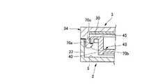
蓋体3には、垂下前壁部31に代えて、前壁部34が形成される。前壁部34は、容器本体2に合致する平面外形輪郭で皿状に形成された環状周壁部30の前端部に、その一部として形成されており、閉蓋状態では、容器本体2の前壁22の外面とほぼ段差なく形成される。蓋体3には、これより化粧料収納部5内に垂下させて爪部70aが形成される。爪部70aには、その下端に、これより後方へ向けて突出させたフック70bが形成される。他方、化粧料皿4の枠部45前端には、フック70bに係合される係合部70cが垂下形成される。これらフック70bと係合部70cにより、フック部が構成される。   Instead of the drooping front wall 31, a front wall 34 is formed on the lid 3. The front wall portion 34 is formed as a part of the front end portion of the annular peripheral wall portion 30 formed in a dish shape with a planar outer contour that matches the container main body 2. The outer surface of the wall 22 is formed almost without a step. A claw part 70 a is formed on the lid body 3 by being suspended in the cosmetic storage part 5. A hook 70b is formed at the lower end of the claw portion 70a so as to protrude rearward. On the other hand, at the front end of the frame portion 45 of the cosmetic dish 4, an engaging portion 70c that engages with the hook 70b is suspended. These hooks 70b and engaging portions 70c constitute a hook portion.

開蓋操作の際には、押圧壁29の押圧操作で化粧料皿4が後方へのスライド移動することに伴って係合部70cが後方へ移動することで、係合部70cとフック70bとの係合が解除される。   When the lid opening operation is performed, the engaging portion 70c moves rearward as the cosmetic dish 4 slides backward by the pressing operation of the pressing wall 29, whereby the engaging portion 70c and the hook 70b are moved. Is disengaged.

次に、本発明にかかるコンパクト容器の第2実施形態を詳細に説明する。本実施形態にあっては、第1実施形態との差異のみを説明する。   Next, a second embodiment of the compact container according to the present invention will be described in detail. In the present embodiment, only differences from the first embodiment will be described.

本実施形態にかかるコンパクト容器1は、押圧壁29の押圧操作によって化粧料皿4が前方へスライド移動する形態である。図11から13に示すように、このコンパクト容器1では、化粧料皿4の側壁は、前後方向ほぼ全長に亘って外方へ延設されている。化粧料皿4の側壁には、傾斜部42が形成される。傾斜部42の傾斜面部42aは、後皿部44の側壁外面から後方へ向かうにしたがって次第に内方に傾斜させて形成される。止め部42bは、傾斜面部42aの後端に隣接した化粧料皿4側壁により形成される。他方、突起部26の傾斜面26aは、前後方向中央から前方に向かって形成される。開蓋操作により、押圧壁29が内方へ弾性変形することで、突起部26の傾斜面26aが傾斜面部42aを摺動し、これに伴って、傾斜部42を介して化粧料皿4を前方へスライド移動させる。   The compact container 1 according to the present embodiment is configured such that the cosmetic dish 4 slides forward by a pressing operation of the pressing wall 29. As shown in FIGS. 11 to 13, in this compact container 1, the side wall of the cosmetic dish 4 extends outward substantially over the entire length in the front-rear direction. An inclined portion 42 is formed on the side wall of the cosmetic dish 4. The inclined surface portion 42 a of the inclined portion 42 is formed so as to be gradually inclined inward as it goes rearward from the outer surface of the side wall of the rear dish portion 44. The stopper 42b is formed by the side wall of the cosmetic dish 4 adjacent to the rear end of the inclined surface 42a. On the other hand, the inclined surface 26a of the protrusion 26 is formed from the front-rear direction center toward the front. As the pressing wall 29 is elastically deformed inward by the opening operation, the inclined surface 26a of the protrusion 26 slides on the inclined surface portion 42a. Accordingly, the cosmetic dish 4 is moved through the inclined portion 42. Slide forward.

本実施形態においては、嵌着部は化粧料皿収納部5の前後方向ほぼ全長に亘って形成される。具体的には、第2嵌着部82は、隙間を挟んで隣り合う、外方へ延設した化粧料皿4の側壁と、枠部45とで構成される。第1嵌着部81は、第2嵌着部82に面する容器本体2の上縁部20aで形成されている。   In the present embodiment, the fitting portion is formed over substantially the entire length of the cosmetic dish storage portion 5 in the front-rear direction. Specifically, the second fitting portion 82 is configured by the side wall of the cosmetic dish 4 that is adjacent to each other across the gap and extends outward, and the frame portion 45. The first fitting portion 81 is formed by the upper edge portion 20 a of the container body 2 facing the second fitting portion 82.

また、隙間Sは化粧料皿4と、容器本体2の前壁22との間に設けられ、隙間Sには板バネ60が設けられる。化粧料皿4が前方へスライド移動して隙間Sの領域が狭まると、板バネ60は、化粧料皿4に押圧されて隙間S内で弾性変形し、押圧部29の押圧操作を解除すると、板バネ60が弾性復原することで化粧料皿4を元の位置まで後方へスライド移動させる。   Further, the gap S is provided between the cosmetic dish 4 and the front wall 22 of the container body 2, and the leaf spring 60 is provided in the gap S. When the cosmetic dish 4 slides forward and the area of the gap S narrows, the leaf spring 60 is pressed by the cosmetic dish 4 and elastically deforms in the gap S, and when the pressing operation of the pressing portion 29 is released, As the leaf spring 60 is elastically restored, the cosmetic dish 4 is slid rearward to the original position.

本実施形態にかかるコンパクト容器1のフック部の形状を図14に示す。蓋体3には、通常の前壁部34が形成される。蓋体3と化粧料皿4の間にはフック部が形成される。フック部は、化粧料皿4の枠部45前端に形成され、後述するフック76を挿抜自在に挿通する孔状の係合部75と、蓋体3の天板32より垂下形成され、その先端が前方に突出することで、係合部75に挿入しかつ係脱自在に係合するフック76とから構成される。   The shape of the hook part of the compact container 1 concerning this embodiment is shown in FIG. A normal front wall 34 is formed on the lid 3. A hook portion is formed between the lid 3 and the cosmetic dish 4. The hook portion is formed at the front end of the frame portion 45 of the cosmetic dish 4, and is formed to hang down from a hole-like engagement portion 75 through which a hook 76, which will be described later, is removably inserted, and the top plate 32 of the lid 3. Projecting forward, the hook 76 is inserted into the engaging portion 75 and detachably engaged.

また、前皿部43の前壁には、これより前方へ突設され、その上面に前方から後方にかけて上昇する傾斜面77aを有する突片77が形成される。   Further, the front wall of the front plate portion 43 is formed with a protruding piece 77 having an inclined surface 77a that protrudes forward from the front wall and rises from the front to the rear.

さらに、枠部45の前端に第1傾斜部45aが形成され、蓋体3の前壁部34の内側に第1傾斜部45aに対応させた第2傾斜部34aが形成される。   Further, a first inclined portion 45 a is formed at the front end of the frame portion 45, and a second inclined portion 34 a corresponding to the first inclined portion 45 a is formed inside the front wall portion 34 of the lid 3.

開蓋時には、係合部75が、化粧料皿4とともに前方にスライド移動し、フック76から逸脱してフック部の係合が解除される。これに伴い、突片77がフック76の後端に当接しながらこれを押し上げつつスライドし、係合部75との係合が解除されたフック76を上方へ押し上げ、同時に、第1傾斜部45aが第2傾斜部34aに当接してこれを押し上げて蓋体3を浮き上がらせる。そして、浮き上がった蓋体3を手指などで開放する。   When the lid is opened, the engaging portion 75 slides forward together with the cosmetic dish 4, deviates from the hook 76, and the engagement of the hook portion is released. Accordingly, the projecting piece 77 slides while pushing up and pushing up the rear end of the hook 76, and pushes up the hook 76 released from the engagement with the engaging portion 75, and at the same time, the first inclined portion 45 a. Comes into contact with the second inclined portion 34a and pushes it up to lift the lid 3 up. Then, the lifted lid 3 is opened with fingers.

さらに、フック76前端と係合部75の前端とに、互いに対面する一対の傾斜面78が形成されており、使用後は、蓋体3を手指で容器本体2方向に押し込むと、これら傾斜面78が互いに摺動することによって、化粧料皿4を前方へスライド移動させ、スムースに係合部76にフック75が係合される。   Furthermore, a pair of inclined surfaces 78 facing each other are formed at the front end of the hook 76 and the front end of the engaging portion 75. After use, when the lid 3 is pushed toward the container body 2 with fingers, these inclined surfaces are formed. By sliding 78, the cosmetic dish 4 is slid forward, and the hook 75 is smoothly engaged with the engaging portion 76.

フック部は、他に図15に示すように、突片77が形成されない形態のものもある。この場合は、フック部の係合が解除された後、第1傾斜部45aと第2傾斜部34aのみで蓋体3を浮き上がらせる。   In addition, as shown in FIG. 15, there is a hook portion in which the protruding piece 77 is not formed. In this case, after the hook portion is disengaged, the lid body 3 is lifted only by the first inclined portion 45a and the second inclined portion 34a.

次に、本実施形態にかかるコンパクト容器1におけるフック部の変形例を説明する。図16に開蓋段階のフック部の形状を示す。本変形例では、フック部は後述する押し上げフック71と、係合部31aとで構成される。また、本変形例は、蓋体3には、垂下前壁部31が形成されるタイプのものである。化粧料皿4には、前皿部43の前壁外面から前方へ突出させて押し上げフック71が形成される。押し上げフック71は、前皿部43の前壁外面から前方へ突出させた突出部71aと、突出部71aの前端に設けられ、上下方向へ可撓変形可能な可撓部71bと、可撓部71bの前端にほぼ断面三角形状に形成される押し上げ部72とから構成される。押し上げ部72には、その下面に化粧料皿4の前方へのスライド移動に従い、順次上昇する上向き傾斜面72aが形成され、また、上面に化粧料皿4の前方へのスライド移動に従い、係合部31aを押し上げる押し上げ面72bが形成される。また、容器本体2には、その前壁22に、押し上げフック71を前後方向に貫通する孔部22aが形成され、孔部22aには、押し上げ部72のスライド方向に順次上昇させて形成され、上向き傾斜面72aを摺接するガイド斜面22bが設けられる。   Next, the modification of the hook part in the compact container 1 concerning this embodiment is demonstrated. FIG. 16 shows the shape of the hook portion at the opening stage. In the present modification, the hook portion includes a push-up hook 71 (to be described later) and an engaging portion 31a. Further, in this modification, the lid 3 is of a type in which a drooping front wall portion 31 is formed. A push-up hook 71 is formed on the cosmetic dish 4 so as to protrude forward from the outer surface of the front wall of the front dish portion 43. The push-up hook 71 is provided at the front end of the protrusion 71a, which protrudes forward from the front wall outer surface of the front plate portion 43, the flexible portion 71b that can be flexibly deformed in the vertical direction, and the flexible portion. It is comprised from the front end of 71b and the pushing-up part 72 formed in a cross-sectional triangle shape substantially. The push-up part 72 is formed with an upward inclined surface 72a that rises in accordance with the forward slide movement of the cosmetic dish 4 on the lower surface thereof, and is engaged on the upper surface in accordance with the forward slide movement of the cosmetic dish 4 A push-up surface 72b that pushes up the portion 31a is formed. Further, the container body 2 is formed with a hole 22a penetrating the push-up hook 71 in the front-rear direction on the front wall 22 thereof, and the hole 22a is formed by being sequentially raised in the sliding direction of the push-up part 72, A guide slope 22b is provided in sliding contact with the upward inclined surface 72a.

容器本体2の前壁22上方には、蓋体3に係止される第1係止部73が突出形成され、蓋体3の垂下前壁部31には、第1係止部73に面して、第1係止部73を係脱自在に係止させる凹状の第2係止部74が形成される。第1係止部73および第2係止部74が互いに係止されて閉蓋状態が保持される。   Above the front wall 22 of the container body 2, a first locking portion 73 that is locked to the lid body 3 is formed so as to protrude. The hanging front wall portion 31 of the lid body 3 faces the first locking portion 73. Thus, a concave second locking portion 74 that locks the first locking portion 73 in a detachable manner is formed. The first locking portion 73 and the second locking portion 74 are locked to each other and the closed state is maintained.

開蓋操作の際は、押圧壁29の押圧操作により化粧料皿4が前方へスライド移動すると、これに伴って押し上げフック71が前方へ押し込まれる。押し上げ部72は、その上向き傾斜面72aがガイド斜面22bに摺接されることにより、可撓部71bが上方へ可撓変形しながら順次上昇し、押し上げ面72が蓋体3の係合部31aに当接してこれを押し上げる。蓋体3が押し上げられたことによって、第1係止部72および第2係止部73の係止状態が解除される。   During the opening operation, when the cosmetic dish 4 is slid forward by the pressing operation of the pressing wall 29, the push-up hook 71 is pushed forward accordingly. When the upwardly inclined surface 72a is slidably contacted with the guide inclined surface 22b, the push-up portion 72 sequentially rises while the flexible portion 71b is flexibly deformed upward, and the push-up surface 72 is engaged with the engaging portion 31a of the lid 3. Push it up against it. When the lid 3 is pushed up, the locked state of the first locking portion 72 and the second locking portion 73 is released.

コンパクト容器1の使用後は、蓋体3を押し込み操作をすると、第1係止部73が第2係止部74に係止されて閉蓋される。   After the compact container 1 is used, when the lid 3 is pushed in, the first locking portion 73 is locked to the second locking portion 74 and closed.

次に、本発明にかかるコンパクト容器の第3実施形態を詳細に説明する。本実施形態にあっては、第1実施形態との差異のみを説明する。   Next, a third embodiment of the compact container according to the present invention will be described in detail. In the present embodiment, only differences from the first embodiment will be described.

本実施形態にあっては、図17〜図20に示すように、突起部26は複数形成されるとともに、突起部29に対応させて、傾斜部42も複数形成される。   In the present embodiment, as shown in FIGS. 17 to 20, a plurality of projections 26 are formed, and a plurality of inclined portions 42 are also formed corresponding to the projections 29.

突起部26は、押圧壁29から化粧料皿4に向かって突出させて、これと一体形成される。図示例にあっては、突起部26は、平断面が半円状に形成されており、その前後方向中央から後方にかけて傾斜面26aが形成されている。突起部26は、押圧壁29にほぼ等間隔に5つ並設されている。   The protrusion 26 protrudes from the pressing wall 29 toward the cosmetic dish 4 and is integrally formed therewith. In the illustrated example, the projecting portion 26 has a semicircular flat cross section, and an inclined surface 26a is formed from the center in the front-rear direction to the rear. Five protrusions 26 are arranged on the pressing wall 29 at approximately equal intervals.

容器本体2の後方部側に位置する化粧料皿4の側壁は、外方に延設される。傾斜部42は、突起部26に対面させて、延設された後皿部44の側壁外面に一体形成される。傾斜部42は、突起部26に対応し、これを嵌合可能な大きさであって、その正面断面形状がV字状に凹設されている。傾斜部42は、突起部26に対応させて後皿部44の側壁に5つ並設されている。   The side wall of the cosmetic dish 4 located on the rear side of the container body 2 extends outward. The inclined portion 42 is integrally formed on the outer surface of the side wall of the rear plate portion 44 that extends so as to face the protruding portion 26. The inclined portion 42 corresponds to the protruding portion 26 and has a size that allows the inclined portion 42 to be fitted therein, and the front cross-sectional shape thereof is recessed in a V shape. Five inclined portions 42 are arranged side by side on the side wall of the rear plate portion 44 so as to correspond to the protruding portions 26.

傾斜部42には、前後方向中央から前方にかけて押圧壁29に向かって傾斜される傾斜面部42aが形成される。傾斜面部42aの前端は、傾斜面26aに当接されている。この状態からの押圧操作により、押圧壁29が内方へ弾性変形すると、傾斜面部42aの前方に当接した突起部26の傾斜面26aが傾斜面部42a上を後方に向かって摺動する。これにより傾斜部42には前方へ移動する操作力が発生する。この操作力により傾斜部42を介して化粧料皿4は前方へスライド移動する。突起部26が傾斜部42全体に嵌合されることで、化粧料皿4の前方へのスライド移動が終了する。   The inclined portion 42 is formed with an inclined surface portion 42 a that is inclined toward the pressing wall 29 from the center in the front-rear direction to the front. The front end of the inclined surface portion 42a is in contact with the inclined surface 26a. When the pressing wall 29 is elastically deformed inward by the pressing operation from this state, the inclined surface 26a of the protruding portion 26 contacting the front of the inclined surface portion 42a slides backward on the inclined surface portion 42a. As a result, an operating force that moves forward is generated in the inclined portion 42. The cosmetic dish 4 slides forward through the inclined portion 42 by this operating force. When the protrusion 26 is fitted to the entire inclined portion 42, the sliding movement of the cosmetic dish 4 to the front ends.

本実施形態では、嵌着部は、容器本体2の後方部に形成される。具体的には、隙間を挟んで隣り合う、外方へ延設された化粧料皿4の側壁と、枠部45とにより、第2嵌着部82が形成され、これに面する容器本体2の後方部側の上縁部20aによって第1嵌着部81が形成される。   In the present embodiment, the fitting portion is formed in the rear portion of the container body 2. Specifically, the second fitting portion 82 is formed by the side wall of the cosmetic dish 4 extending outward and adjacent to the gap, and the frame portion 45, and the container body 2 facing the second fitting portion 82. The first fitting portion 81 is formed by the upper edge portion 20a of the rear portion side.

本実施形態にあっては、傾斜部42が突起部26に対応させてこれを嵌合可能な程度の大きさに形成されていた。これによって化粧料皿4の側面に複数の傾斜部42を形成することができる。そして、これら複数の突起部26を複数の傾斜部42に摺動させることにより、これらを1つずつ形成したものに比べて、化粧料皿4のスライド移動をさらに安定させることが可能となるとともに、押圧壁29の押圧操作位置によらず、安定した操作性を確保することが可能となる。   In the present embodiment, the inclined portion 42 is formed in a size that can be fitted to the protruding portion 26 so as to be fitted thereto. Accordingly, a plurality of inclined portions 42 can be formed on the side surface of the cosmetic dish 4. Then, by sliding the plurality of protrusions 26 to the plurality of inclined portions 42, the sliding movement of the cosmetic dish 4 can be further stabilized as compared with the case where these are formed one by one. Stable operability can be ensured regardless of the pressing operation position of the pressing wall 29.

本実施形態にあっては、化粧料皿4が前方にスライド移動する形態を説明したが、後方にスライド移動する形態であってもよい。傾斜面26aは、突起部26の前後方向中央から後方に形成され、傾斜面部42aは、傾斜部42の前後方向中央から後方に形成することとなる。そして、傾斜面26の前端が傾斜面部42aの後端に当接された状態に配置される。   In the present embodiment, the form in which the cosmetic dish 4 slides forward has been described, but a form in which the cosmetic dish 4 slides back may be used. The inclined surface 26a is formed rearward from the center in the front-rear direction of the protrusion 26, and the inclined surface portion 42a is formed rearward from the center in the front-rear direction of the inclined portion 42. And the front end of the inclined surface 26 is arrange | positioned in the state contact | abutted to the rear end of the inclined surface part 42a.

本実施形態にあっても、上記第1実施形態および第2実施形態と同様、これらの移動方向に応じた様々なフック部を形成することもできる。   Even in the present embodiment, as in the first embodiment and the second embodiment, various hook portions corresponding to the moving directions can be formed.

次に本実施形態にかかるコンパクト容器1の短尺スリット27の変形例を説明する。図21〜22に示すように、短尺スリット27は、容器本体2の前後方向略中央から後壁21前方の適宜位置にかけて形成されており、かつ、底壁25の下方から上方にかけて徐々に内側に傾斜させて貫通させた孔状に形成されている。これにより、容器本体2底面から短尺スリット27を介して化粧料皿収納部5内が露見せず、意匠性に優れたコンパクト容器1を製作することが可能となる。   Next, a modified example of the short slit 27 of the compact container 1 according to the present embodiment will be described. As shown in FIGS. 21 to 22, the short slit 27 is formed from approximately the center in the front-rear direction of the container body 2 to an appropriate position in front of the rear wall 21, and gradually inward from the bottom to the top of the bottom wall 25. It is formed in a hole shape that is inclined and penetrated. Thereby, the inside of the cosmetic dish storage part 5 is not exposed from the bottom surface of the container body 2 through the short slit 27, and the compact container 1 having excellent design can be manufactured.

上記、第1ないし第3実施形態においては、短尺スリット27は底壁25の後方部側に形成されていたがこれに限られず、前方部側の底壁25に形成してもよい。この場合は、押圧壁29は、容器本体2の前方側の側壁23、24に形成されることなり、これに対応させて、突起部26、傾斜部42を形成することとなる。   In the first to third embodiments described above, the short slit 27 is formed on the rear side of the bottom wall 25, but is not limited thereto, and may be formed on the bottom wall 25 on the front side. In this case, the pressing wall 29 is formed on the side walls 23 and 24 on the front side of the container main body 2, and the protruding portion 26 and the inclined portion 42 are formed correspondingly.

第1ないし第3実施形態にあっては、突起部26は押圧壁29に形成されており、これに面して、傾斜部42は化粧料皿4に形成されていた。しかしながら、突起部26を化粧料皿4に形成し、これに対応する傾斜部42を押圧壁29に形成しても良いことはもちろんである。   In the first to third embodiments, the protruding portion 26 is formed on the pressing wall 29, and the inclined portion 42 is formed on the cosmetic dish 4 facing this. However, it goes without saying that the protrusion 26 may be formed on the cosmetic dish 4 and the inclined portion 42 corresponding thereto may be formed on the pressing wall 29.

第1ないし第3実施形態にあっては、突起部26は、左右の押圧壁29より化粧料皿4側へ平断面が半円形状に突出させて形成されていた。しかしながら、突起部26の形状はこれに限られない。例えば突起部26は、傾斜面部42aに対応させて、押圧壁29若しくは化粧料皿4の側壁外面に傾斜面26aを形成するのみでもよい。   In the first to third embodiments, the protrusion 26 is formed such that the flat cross section protrudes from the left and right pressing walls 29 toward the cosmetic dish 4 in a semicircular shape. However, the shape of the protrusion 26 is not limited to this. For example, the protrusion 26 may only form the inclined surface 26a on the outer surface of the side wall of the pressing wall 29 or the cosmetic dish 4 so as to correspond to the inclined surface portion 42a.

第1ないし第3実施形態にあっては、容器本体2および化粧料皿4の嵌着手段として、第1嵌着部と第2嵌着部とで構成される嵌着部を例示していた。しかしながら、嵌着手段はこれに限られず、化粧料皿4が容器本体2内に嵌着できればよい。例えば、化粧料皿4の側壁外面の適宜位置に突起を設け、この突起に面した容器本体2に、前記突起に係合する突起を設けてもよい。ただし、上記実施形態のように、容器本体2内に化粧料皿4を嵌着する手段を、嵌着部として、上縁部20aで形成された第1嵌着部81と、枠部45と化粧料皿4側壁(傾斜部42を含む)との間の隙間で形成された第2嵌着部82とから構成すれば、新たな部品を形成することなく、生産性がより良好となる。   In 1st thru | or 3rd embodiment, the fitting part comprised by the 1st fitting part and the 2nd fitting part was illustrated as a fitting means of the container main body 2 and the cosmetic dish 4 . However, the fitting means is not limited to this, as long as the cosmetic dish 4 can be fitted into the container body 2. For example, a protrusion may be provided at an appropriate position on the outer surface of the side wall of the cosmetic dish 4, and a protrusion that engages with the protrusion may be provided on the container body 2 facing the protrusion. However, as in the above-described embodiment, the means for fitting the cosmetic dish 4 into the container body 2 is used as a fitting portion, and the first fitting portion 81 formed by the upper edge portion 20a, the frame portion 45, If it comprises the 2nd fitting part 82 formed in the clearance gap between the cosmetic dish 4 side walls (including the inclination part 42), productivity will become more favorable, without forming a new part.

本発明にかかるコンパクト容器の好適な第1実施形態を示す、上方から見た分解斜視図である。It is the disassembled perspective view seen from the upper direction which shows suitable 1st Embodiment of the compact container concerning this invention. 図1に示したコンパクト容器を、下方から見た分解斜視図である。It is the disassembled perspective view which looked at the compact container shown in FIG. 1 from the downward direction. 図1に示したコンパクト容器の平断面図である。It is a plane sectional view of the compact container shown in FIG. 図1に示したコンパクト容器の側断面図である。It is a sectional side view of the compact container shown in FIG. 図3に示したコンパクト容器のA−A断面図である。It is AA sectional drawing of the compact container shown in FIG. 図1のコンパクト容器の押圧壁を押圧操作した状態を示す、平断面図である。It is a plane sectional view which shows the state which pressed the pressing wall of the compact container of FIG. 図6に示した押圧操作状態のコンパクト容器の側断面図である。It is a sectional side view of the compact container of the press operation state shown in FIG. 図1のコンパクト容器の弾性変形部材として弓形状バネを形成した状態を示す、隙間内の要部拡大平断面図である。It is a principal part expanded plane sectional view in the clearance gap which shows the state which formed the bow-shaped spring as an elastic deformation member of the compact container of FIG. 図1のコンパクト容器の弾性変形部材としてゴム状バネを配設した状態を示す、隙間内の要部拡大側断面図である。It is a principal part expanded side sectional view in the clearance gap which shows the state which has arrange | positioned the rubber-like spring as an elastic deformation member of the compact container of FIG. 第1実施形態にかかるコンパクト容器のフック部の変形例を示す要部拡大側断面図である。It is a principal part expanded side sectional view which shows the modification of the hook part of the compact container concerning 1st Embodiment. 本発明にかかるコンパクト容器の第2実施形態示す平断面図である。It is a plane sectional view showing a 2nd embodiment of a compact container concerning the present invention. 図11のコンパクト容器の押圧壁を押圧した状態を示す、平断面図である。It is a plane sectional view which shows the state which pressed the pressing wall of the compact container of FIG. 図12の押圧操作状態のコンパクト容器の裏面図である。It is a reverse view of the compact container of the press operation state of FIG. 第2実施形態にかかるコンパクト容器のフック部を示す要部拡大側断面図である。It is a principal part expanded side sectional view which shows the hook part of the compact container concerning 2nd Embodiment. 第2実施形態にかかるコンパクト容器における、フック部を示す要部拡大側断面図である。It is a principal part expanded side sectional view which shows the hook part in the compact container concerning 2nd Embodiment. 第2実施形態にかかるコンパクト容器における、フック部の変形例を示す開蓋過程の要部拡大側断面図である。It is a principal part expanded side sectional view of the lid opening process which shows the modification of a hook part in the compact container concerning 2nd Embodiment. 本発明にかかるコンパクト容器の第3実施形態を示す、上方から見た分解斜視図である。It is the disassembled perspective view seen from the top which shows 3rd Embodiment of the compact container concerning this invention. 図17に示したコンパクト容器の平断面図である。It is a plane sectional view of the compact container shown in FIG. 図17に示したコンパクト容器の側断面図である。It is a sectional side view of the compact container shown in FIG. 図18に示したコンパクト容器のB−B断面図である。It is BB sectional drawing of the compact container shown in FIG. 第3実施形態にかかるコンパクト容器における、短尺スリットの変形例を示す平断面図である。It is a plane sectional view showing a modification of a short slit in a compact container concerning a 3rd embodiment. 図21に示したコンパクト容器のC−C断面図である。It is CC sectional drawing of the compact container shown in FIG.

符号の説明Explanation of symbols

1 コンパクト容器
2 容器本体
3 蓋体
4 化粧料皿
21 後壁
22 前壁
23 左側壁
24 右側壁
25 底壁
26 突起部
27 短尺スリット
29 押圧壁
31 垂下前壁部
31a 係合部
40 前端部
41 フック
42 傾斜部
S 隙間
DESCRIPTION OF SYMBOLS 1 Compact container 2 Container body 3 Cover body 4 Cosmetic dish 21 Rear wall 22 Front wall 23 Left side wall 24 Right side wall 25 Bottom wall 26 Projection part 27 Short slit 29 Press wall 31 Hanging front wall part 31a Engagement part 40 Front end part 41 Hook 42 Inclined part S Clearance

Claims (4)

蓋体が後壁に回動自在に連結された容器本体と、
該容器本体の左右側壁に沿って、その前方部若しくは後方部の底壁に形成される一対の短尺スリットと、
これら一対の短尺スリットに面して、該左右側壁に弾性変形可能に形成される一対の押圧壁と、
該容器本体内に、左右側壁の間で前後方向スライド自在に嵌着される化粧料皿と、
該化粧料皿と該蓋体の間に、該化粧料皿と該蓋体とを係脱自在に係合して該容器本体の閉蓋状態を保持し、該化粧料皿のスライド移動によって、その係合を解除するフック部と、
該押圧壁若しくは該化粧料皿のいずれか一方に、一体形成される突起部と、
該突起部に面して、該化粧料皿若しくは該押圧壁に一体形成され、該押圧壁の押圧操作で、該突起部を摺動自在に摺動させて該化粧料皿を前方若しくは後方のいずれか一方にスライド移動させる傾斜部とを有することを特徴とするコンパクト容器。
A container body whose lid is rotatably connected to the rear wall;
A pair of short slits formed in the bottom wall of the front part or the rear part along the left and right side walls of the container body,
Facing these pair of short slits, a pair of pressing walls formed on the left and right side walls so as to be elastically deformable,
In the container body, a cosmetic dish that is slidably fitted in the front-rear direction between the left and right side walls;
Between the cosmetic dish and the lid body, the cosmetic dish and the lid body are detachably engaged to maintain the closed state of the container body, and by sliding the cosmetic dish, A hook portion for releasing the engagement;
A protrusion formed integrally with either the pressing wall or the cosmetic dish;
Facing the protrusion, it is integrally formed with the cosmetic dish or the pressing wall, and the pressing operation of the pressing wall allows the protrusion to slide slidably to move the cosmetic dish forward or backward. A compact container comprising an inclined portion that is slid and moved to either one.
前記突起部は複数形成されるとともに、該突起部に対応させて、前記傾斜部も複数形成されることを特徴とする請求項1に記載のコンパクト容器。   2. The compact container according to claim 1, wherein a plurality of the protruding portions are formed, and a plurality of the inclined portions are formed corresponding to the protruding portions. 前記化粧料皿と、前記容器本体の前記後壁および前記前壁のいずれかとの間には隙間が形成され、該隙間内には、前方若しくは後方へスライド移動した該化粧料皿により弾性変形され、その弾性復原力によって該化粧料皿を元の位置へ押し戻す弾性変形部材が設けられることを特徴とする請求項1または2に記載のコンパクト容器。   A gap is formed between the cosmetic dish and one of the rear wall and the front wall of the container body, and the gap is elastically deformed by the cosmetic dish slid forward or backward in the gap. The compact container according to claim 1, further comprising an elastic deformation member that pushes the cosmetic dish back to its original position by the elastic restoring force. 前記蓋体には、その前端に前記容器本体の前記前壁全体をその前方から覆う垂下前壁部が形成されることを特徴とする請求項1〜3いずれかの項に記載のコンパクト容器。   The compact container according to any one of claims 1 to 3, wherein a drooping front wall portion that covers the entire front wall of the container body from the front is formed at the front end of the lid.
JP2008231683A 2008-09-10 2008-09-10 Compact container Expired - Fee Related JP5260199B2 (en)

Priority Applications (3)

Application Number Priority Date Filing Date Title
JP2008231683A JP5260199B2 (en) 2008-09-10 2008-09-10 Compact container
US12/554,071 US8302614B2 (en) 2008-09-10 2009-09-04 Compact case
FR0956091A FR2935592B1 (en) 2008-09-10 2009-09-08 POWDER

Applications Claiming Priority (1)

Application Number Priority Date Filing Date Title
JP2008231683A JP5260199B2 (en) 2008-09-10 2008-09-10 Compact container

Publications (2)

Publication Number Publication Date
JP2010063566A true JP2010063566A (en) 2010-03-25
JP5260199B2 JP5260199B2 (en) 2013-08-14

Family

ID=41728489

Family Applications (1)

Application Number Title Priority Date Filing Date
JP2008231683A Expired - Fee Related JP5260199B2 (en) 2008-09-10 2008-09-10 Compact container

Country Status (3)

Country Link
US (1) US8302614B2 (en)
JP (1) JP5260199B2 (en)
FR (1) FR2935592B1 (en)

Cited By (1)

* Cited by examiner, † Cited by third party
Publication number Priority date Publication date Assignee Title
KR20230123291A (en) * 2022-02-16 2023-08-23 정규철 Packaging container with slide-type opening and closing structure

Families Citing this family (11)

* Cited by examiner, † Cited by third party
Publication number Priority date Publication date Assignee Title
CN102753053B (en) * 2010-02-15 2015-07-08 吉田塑胶工业株式会社 Compact container with built-in hinge unit and method for manufacturing compact container with built-in hinge unit
FR2968903B1 (en) * 2010-12-17 2013-08-16 Oreal DEVICE FOR PACKAGING A COSMETIC PRODUCT
GB2513578A (en) * 2013-04-30 2014-11-05 Toly Man Ltd Compact housing for a cosmetic container
WO2015042417A1 (en) 2013-09-19 2015-03-26 Mortis Simons Monifa L Cosmetics storage assembly
FR3035304A1 (en) * 2015-04-24 2016-10-28 Qualipac Sa BOX BASE HAVING A SHOCK ABSORBER DEVICE AND HOUSING COMPRISING SUCH A BASE
USD821034S1 (en) * 2016-03-16 2018-06-19 HCT Group Holdings Limited Cosmetic compact
USD863685S1 (en) 2017-11-27 2019-10-15 Mary Kay Inc. Cosmetic compact
USD836842S1 (en) 2017-11-27 2018-12-25 Mary Kay Inc. Cosmetic compact
USD843660S1 (en) 2017-11-27 2019-03-19 Mary Kay Inc. Cosmetic compact
USD850006S1 (en) 2017-11-27 2019-05-28 Mary Kay Inc. Cosmetic compact
KR20210024790A (en) 2019-08-26 2021-03-08 (주) 휴마스 Remote water sampling apparatus and water quality monitoring system by using the same

Citations (2)

* Cited by examiner, † Cited by third party
Publication number Priority date Publication date Assignee Title
JPS5973213U (en) * 1982-11-09 1984-05-18 吉田工業株式会社 Side push-type compact container
JP2007289290A (en) * 2006-04-21 2007-11-08 Yoshida Industry Co Ltd Compact container

Family Cites Families (3)

* Cited by examiner, † Cited by third party
Publication number Priority date Publication date Assignee Title
JP4757509B2 (en) * 2005-03-04 2011-08-24 吉田プラ工業株式会社 Cosmetic container
JP4920259B2 (en) * 2006-01-18 2012-04-18 吉田プラ工業株式会社 Compact container
US7870862B2 (en) * 2006-04-21 2011-01-18 Yoshida Industry Co., Ltd. Vanity case

Patent Citations (2)

* Cited by examiner, † Cited by third party
Publication number Priority date Publication date Assignee Title
JPS5973213U (en) * 1982-11-09 1984-05-18 吉田工業株式会社 Side push-type compact container
JP2007289290A (en) * 2006-04-21 2007-11-08 Yoshida Industry Co Ltd Compact container

Cited By (2)

* Cited by examiner, † Cited by third party
Publication number Priority date Publication date Assignee Title
KR20230123291A (en) * 2022-02-16 2023-08-23 정규철 Packaging container with slide-type opening and closing structure
KR102672488B1 (en) 2022-02-16 2024-06-04 정규철 Packaging container with slide-type opening and closing structure

Also Published As

Publication number Publication date
FR2935592A1 (en) 2010-03-12
JP5260199B2 (en) 2013-08-14
FR2935592B1 (en) 2014-04-18
US20100059081A1 (en) 2010-03-11
US8302614B2 (en) 2012-11-06

Similar Documents

Publication Publication Date Title
JP5260199B2 (en) Compact container
JP2006239214A (en) Cosmetic container
US6902333B2 (en) Container capable of moving a contained article in longitudinal direction
JP5241390B2 (en) Compact container
JP4954597B2 (en) Compact container
JP5241389B2 (en) Compact container
JP2006345959A (en) Cosmetic container
JP5260200B2 (en) Compact container
JP4657592B2 (en) Compact container
JP4707429B2 (en) Sliding compact container
JP7221065B2 (en) container with lid
JP4549653B2 (en) Cosmetic container
JP4920294B2 (en) Compact container
JP5707156B2 (en) Compact container
JP7292809B2 (en) compact container
JP4037396B2 (en) Liquid storage pot
JP4970911B2 (en) Cosmetic container
JP5642431B2 (en) Compact container
JPH07227312A (en) Cosmetic container
JP2928450B2 (en) Handle mounting structure for liquid container
JPH07227313A (en) Cosmetic container
JP5785783B2 (en) Compact container
JPH08150015A (en) Face powder container
JP5496611B2 (en) Compact container
JPH08164018A (en) Toilet articles vessel

Legal Events

Date Code Title Description
A621 Written request for application examination

Free format text: JAPANESE INTERMEDIATE CODE: A621

Effective date: 20110831

TRDD Decision of grant or rejection written
A01 Written decision to grant a patent or to grant a registration (utility model)

Free format text: JAPANESE INTERMEDIATE CODE: A01

Effective date: 20130409

A61 First payment of annual fees (during grant procedure)

Free format text: JAPANESE INTERMEDIATE CODE: A61

Effective date: 20130425

FPAY Renewal fee payment (event date is renewal date of database)

Free format text: PAYMENT UNTIL: 20160502

Year of fee payment: 3

R150 Certificate of patent or registration of utility model

Free format text: JAPANESE INTERMEDIATE CODE: R150

LAPS Cancellation because of no payment of annual fees