JP2010061998A - Battery, and battery pack - Google Patents
Battery, and battery pack Download PDFInfo
- Publication number
- JP2010061998A JP2010061998A JP2008226565A JP2008226565A JP2010061998A JP 2010061998 A JP2010061998 A JP 2010061998A JP 2008226565 A JP2008226565 A JP 2008226565A JP 2008226565 A JP2008226565 A JP 2008226565A JP 2010061998 A JP2010061998 A JP 2010061998A
- Authority
- JP
- Japan
- Prior art keywords
- battery
- fixing
- exterior body
- surrounding member
- surrounding
- Prior art date
- Legal status (The legal status is an assumption and is not a legal conclusion. Google has not performed a legal analysis and makes no representation as to the accuracy of the status listed.)
- Pending
Links
Images


Classifications
-
- Y—GENERAL TAGGING OF NEW TECHNOLOGICAL DEVELOPMENTS; GENERAL TAGGING OF CROSS-SECTIONAL TECHNOLOGIES SPANNING OVER SEVERAL SECTIONS OF THE IPC; TECHNICAL SUBJECTS COVERED BY FORMER USPC CROSS-REFERENCE ART COLLECTIONS [XRACs] AND DIGESTS
- Y02—TECHNOLOGIES OR APPLICATIONS FOR MITIGATION OR ADAPTATION AGAINST CLIMATE CHANGE
- Y02E—REDUCTION OF GREENHOUSE GAS [GHG] EMISSIONS, RELATED TO ENERGY GENERATION, TRANSMISSION OR DISTRIBUTION
- Y02E60/00—Enabling technologies; Technologies with a potential or indirect contribution to GHG emissions mitigation
- Y02E60/10—Energy storage using batteries
Abstract
Description
この発明は、リチウムイオン二次電池、リチウム二次電池、ポリマー二次電池などの電池と組電池に関し、特定的には素電池を収容する可撓性フィルムからなる外装体を備えた電池と組電池に関するものである。なお、この明細書と特許請求の範囲では、リチウムイオン二次電池、リチウム二次電池、ポリマー二次電池などのいわゆる電池だけでなく、電気二重層キャパシタなども含む「蓄電デバイス」を総称して「電池」という。 TECHNICAL FIELD The present invention relates to a battery and an assembled battery such as a lithium ion secondary battery, a lithium secondary battery, and a polymer secondary battery, and more specifically, a battery and an assembled battery including an exterior body made of a flexible film that accommodates a unit cell. It relates to batteries. In this specification and claims, not only so-called batteries such as lithium ion secondary batteries, lithium secondary batteries, polymer secondary batteries, but also “electric storage devices” including electric double layer capacitors are collectively referred to. It is called “battery”.
従来から、たとえば、リチウムイオン二次電池等の電池に関しては、多様な用途の拡大に伴って、小型化、軽量化、薄型化、形状の自由度等の要求が高まっている。 2. Description of the Related Art Conventionally, for example, batteries such as lithium ion secondary batteries have been increasingly demanded for downsizing, weight reduction, thickness reduction, shape freedom, and the like with the expansion of various applications.
そこで、このような要求に応えることができるように、素電池を収容する可撓性の外装体を形成するために多層構造のラミネートフィルムが従来から用いられている。ラミネートフィルムは、素電池(電池要素)に面する内面層と、中間層と、外部に面する外面層とから構成される。内面層は、たとえば、ポリエチレン、ポリプロピレン等の耐電解液性とヒートシール性に優れた熱可塑性樹脂からなる。中間層は、たとえば、アルミニウム箔等の可撓性と強度に優れた金属箔からなる。外面層は、たとえば、ポリアミド系樹脂等の電気絶縁性に優れた絶縁樹脂からなる。 Therefore, in order to meet such demands, a laminate film having a multilayer structure has been conventionally used to form a flexible exterior body that accommodates a unit cell. The laminate film is composed of an inner surface layer facing the unit cell (battery element), an intermediate layer, and an outer surface layer facing the outside. The inner surface layer is made of, for example, a thermoplastic resin excellent in electrolytic solution resistance and heat sealability, such as polyethylene and polypropylene. An intermediate | middle layer consists of metal foil excellent in flexibility and intensity | strength, such as aluminum foil, for example. An outer surface layer consists of insulating resin excellent in electrical insulation, such as a polyamide-type resin, for example.
このようなラミネートフィルムからなる外装体の中に素電池を収容した電池(以下、ラミネート型電池という)の構造が、たとえば、特開2007−173223号公報(以下、特許文献1という)に開示されている。 A structure of a battery (hereinafter referred to as a laminate type battery) in which a unit cell is housed in an exterior body made of such a laminate film is disclosed in, for example, Japanese Patent Application Laid-Open No. 2007-173223 (hereinafter referred to as Patent Document 1). ing.
図18は、特許文献1に開示されたラミネート型電池を示す斜視図である。
FIG. 18 is a perspective view showing a laminate type battery disclosed in
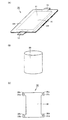
図18(A)に示すように、リチウムイオン二次電池の一つの例として単位電池100では、素電池が合成樹脂フィルム、または、合成樹脂フィルムとアルミニウム箔との積層フィルム、たとえば、ポリプロピレン/アルミニウム/ポリアミド系樹脂からなる可撓性外装材102によって被覆されている。可撓性外装材102の一方の面がエンボス加工等によって成形され、素電池の収納部103を構成し、反対側の他方の面が素電池を覆うために平面状部材104を構成している。正極端子105と負極端子106は、収納部103と平面状部材104の周縁部が熱溶着されて封止された箇所から外部に引き出されている。収納部103と平面状部材104の外側面には、隣接する他の単位電池100の上に積層するために相対的に広い積層面107と108が形成されている。
As shown in FIG. 18A, in the
図18(B)に示すように、他の例の単位電池では、可撓性外装材102の両面がエンボス加工等によって成形され、素電池の収納部103を構成している。正極端子105と負極端子106は、収納部103の外周縁部が熱溶着されて封止された箇所から外部に引き出されている。
As shown in FIG. 18B, in a unit battery of another example, both surfaces of a flexible
図18に示す単位電池100では、正極端子105と負極端子106が可撓性外装材102の封止された同じ側の箇所から引き出されているが、互いに対向する箇所から引き出されていてもよい。
In the
図19は、特許文献1に開示された電池積層体の一つの例を示す斜視図である。
FIG. 19 is a perspective view showing one example of the battery stack disclosed in
図19に示すように、電池積層体1000は、図18(A)に示された単位電池100を8個積層することによって構成されている。具体的には、電池積層体1000は、互いの積層面107と108(図18(A))がほぼ平行になるように4個の単位電池100−1、100−2、100−3、100−4を積み重ねて、温度フューズ装着体2000を配置した後に、さらに4個の単位電池100−5、100−6、100−7、100−8を同様に積み重ねることによって構成されている。8個の単位電池100−1〜100−8の正極端子と負極端子をそれぞれ直列に接続し、端部の負極端子111は充放電の両者に共通の共通端子112とされ、端部の正極端子113は放電回路に接続する放電端子114とともに温度フューズ接続リード線115が接続されている。温度フューズ接続リード線115は、温度フューズ装着体2000の内部に設けた温度フューズへと結合されている。温度フューズから充電回路接続用リード線116が取り出され、充電時に充電電流を供給する充電端子117に接続されている。
As shown in FIG. 19, the
図19には示されていないが、従来の組電池の一例としての電池積層体1000では、積み重ねられた8個の単位電池100−1〜100−8の隣接する積層面107と108の間に接着剤や両面粘着テープ等の化学的な固着手段を配置することによって、8個の単位電池100−1〜100−8の相互の位置が固定されている。
しかしながら、従来のラミネート型電池においては、以下のような問題が生じる恐れがある。 However, the following problems may occur in the conventional laminated battery.
まず、特許文献1に開示されているように単位電池を組み合わせて組電池の一例として電池積層体を構成する場合、複数のラミネート型電池を相互に固定するためには、あるいは、複数のラミネート型電池を所定の筐体内に固定するためには、接着剤や両面粘着テープ等の化学的な固着手段を外装体の表面に配置する必要がある。これは、外装体が可撓性フィルムからなり、その外周面や熱溶着された周縁部の機械的強度が相対的に低いので、その外周面や周縁部が他の構成部材に接触しないように複数のラミネート型電池を配置する必要があるからである。また、外装体の外周面や周縁部の機械的強度が相対的に低いので、ビス、ボルト、リベット等の物理的な固定手段を外装体に直接設けて複数のラミネート型電池を相互に位置決め固定することができない。
First, when a battery stack is configured as an example of an assembled battery by combining unit batteries as disclosed in
次に、従来のラミネート型電池単体を他の構成部材に位置決めて固定する場合にも、外装体の外周面や周縁部の機械的強度が相対的に低いので、ビス、ボルト、リベット等の物理的な固定手段を外装体に直接設けてラミネート型電池を他の構成部材に対して位置決めすることができない。また、外装体の外周面や周縁部の機械的強度が相対的に低いので、外装体に応力が生じた場合に損傷を受けやすく、ラミネート型電池をそのままの形態で取り扱うのが困難であり、従来のラミネート型電池単体の形態は作業性が悪いという問題がある。 Next, when positioning and fixing a conventional laminate type battery alone to other components, the mechanical strength of the outer peripheral surface and the peripheral portion of the outer casing is relatively low, so that physical properties such as screws, bolts, rivets, etc. Therefore, it is impossible to position the laminated battery with respect to other components by directly providing a fixing means on the exterior body. Moreover, since the mechanical strength of the outer peripheral surface and the peripheral portion of the outer package is relatively low, it is easily damaged when stress occurs in the outer package, and it is difficult to handle the laminated battery as it is, A conventional laminate type battery has a problem that workability is poor.
そこで、この発明の目的は、固定または位置決めを容易に行うことができ、作業性を向上させることが可能なラミネート型電池の形態を提供することである。 Accordingly, an object of the present invention is to provide a laminate type battery that can be fixed or positioned easily and can improve workability.
この発明の一つの局面に従った電池は、素電池を収容する可撓性フィルムからなる外装体と、この外装体の外表面の少なくとも一部を包囲し、形状変化により外装体の外表面の少なくとも一部に接触して外装体を保持するようにされた包囲部材とを備える。 A battery according to one aspect of the present invention surrounds at least a part of an outer surface of a flexible film that accommodates a unit cell and the outer surface of the outer package, and changes the shape of the outer surface of the outer package. And an enclosing member configured to contact at least a portion and hold the exterior body.
この発明の一つの局面に従った電池においては、包囲部材が形状変化により外装体の外表面の少なくとも一部に接触して外装体を保持するようにされているので、ビス、ボルト、リベット等の物理的な固定部材を取り付けるための固定箇所形成部材を包囲部材に固着する、あるいは、固定箇所形成部を包囲部材に形成することによって、固定箇所を包囲部材に付与することができる。これにより、接着剤、粘着テープ等の化学的固定手段を用いることなく、単一または複数のラミネート型電池の固定または位置決めを容易に行うことができ、作業性を向上させることができる。 In the battery according to one aspect of the present invention, the surrounding member is configured to come into contact with at least a part of the outer surface of the exterior body by shape change and hold the exterior body, so that a screw, a bolt, a rivet, etc. By fixing the fixing part forming member for attaching the physical fixing member to the surrounding member, or forming the fixing part forming part on the surrounding member, the fixing part can be given to the surrounding member. Thereby, it is possible to easily fix or position a single or a plurality of laminate-type batteries without using a chemical fixing means such as an adhesive or a pressure-sensitive adhesive tape, thereby improving workability.
この発明のもう一つの局面に従った電池は、各々が素電池を収容する可撓性フィルムからなる複数の外装体と、複数の外装体の外表面の少なくとも一部を包囲して、形状変化により複数の外装体の外表面の少なくとも一部に接触して複数の外装体を保持するようにされた包囲部材とを備える。 A battery according to another aspect of the present invention includes a plurality of exterior bodies each made of a flexible film that accommodates unit cells, and surrounds at least a part of the outer surfaces of the plurality of exterior bodies, and changes in shape. A surrounding member configured to contact at least a part of the outer surface of the plurality of exterior bodies and hold the plurality of exterior bodies.
この発明のもう一つの局面に従った電池においては、包囲部材が形状変化により複数の外装体の外表面の少なくとも一部に接触して複数の外装体を保持するようにされているので、包囲部材が複数のラミネート型電池を包囲して保持することができる。これにより、複数のラミネート型電池を単一の形態として取り扱うことができる。また、ビス、ボルト、リベット等の物理的な固定部材を取り付けるための固定箇所形成部材を包囲部材に固着する、あるいは、固定箇所形成部を包囲部材に形成することによって、固定箇所を包囲部材に付与することができるので、接着剤、粘着テープ等の化学的固定手段を用いることなく、複数のラミネート型電池の固定または位置決めを容易に行うことができ、作業性を向上させることができる。 In the battery according to another aspect of the present invention, the surrounding member is configured to contact at least a part of the outer surface of the plurality of exterior bodies by the shape change and hold the plurality of exterior bodies. The member can surround and hold a plurality of laminated batteries. Thereby, a some laminated type battery can be handled as a single form. In addition, a fixing portion forming member for attaching a physical fixing member such as a screw, a bolt, or a rivet is fixed to the surrounding member, or a fixing portion forming portion is formed on the surrounding member, thereby fixing the fixing portion to the surrounding member. Therefore, it is possible to easily fix or position a plurality of laminated batteries without using a chemical fixing means such as an adhesive or a pressure-sensitive adhesive tape, thereby improving workability.
この発明の一つの局面またはもう一つの局面に従った電池において、包囲部材は、熱収縮により外装体の外表面の少なくとも一部に接触して外装体を保持するようにされていることが好ましい。 In the battery according to one aspect or another aspect of the present invention, it is preferable that the surrounding member is configured to be in contact with at least a part of the outer surface of the exterior body by heat shrinkage and hold the exterior body. .
このように構成することによって、熱収縮作用を利用して外装体を包囲して保持することを容易に行うことができる。また、包囲部材と外装体の外表面との密着性を高めることにより、包囲部材の保持性能を向上させることができる。 By configuring in this way, it is possible to easily surround and hold the exterior body using the heat shrinkage action. Moreover, the holding | maintenance performance of an enclosure member can be improved by improving the adhesiveness of an enclosure member and the outer surface of an exterior body.
また、この発明の一つの局面またはもう一つの局面に従った電池において、包囲部材には、包囲部材の外側から外装体の外表面に到達する貫通孔が形成されていることが好ましい。 In the battery according to one aspect or another aspect of the present invention, it is preferable that the surrounding member is formed with a through hole that reaches the outer surface of the exterior body from the outside of the surrounding member.
このように構成することによって、貫通孔を通じて、素電池で発生した熱を外装体の外表面から包囲部材の外側に放出することができるので、電池の放熱性を高めることができる。 With this configuration, heat generated in the unit cell can be released from the outer surface of the exterior body to the outside of the enclosing member through the through hole, so that the heat dissipation of the battery can be improved.
さらに、この発明の一つの局面またはもう一つの局面に従った電池は、素電池の正極および負極のそれぞれに電気的に接続され、外装体から突出して延びる正極接続端子および負極接続端子とをさらに備え、包囲部材には、正極接続端子または負極接続端子の少なくともいずれかに近い部分に切欠きが形成されていることが好ましい。 Furthermore, the battery according to one aspect or another aspect of the present invention further includes a positive electrode connection terminal and a negative electrode connection terminal that are electrically connected to the positive electrode and the negative electrode of the unit cell and extend from the outer package. The surrounding member is preferably provided with a notch in a portion close to at least one of the positive electrode connecting terminal and the negative electrode connecting terminal.
このように構成することによって、素電池で発生した熱を、切欠きによって露出した外装体の外表面から外側に放出することができるので、電池の放熱性を高めることができる。 With this configuration, heat generated in the unit cell can be released to the outside from the outer surface of the exterior body exposed by the notch, so that the heat dissipation of the battery can be improved.
さらにまた、この発明の一つの局面またはもう一つの局面に従った電池は、素電池の正極および負極のそれぞれに電気的に接続され、外装体から突出して延びる正極接続端子および負極接続端子とをさらに備え、包囲部材が正極接続端子および負極接続端子の延びる方向に沿って延在する長さは、外装体の長さよりも短いことが好ましい。 Furthermore, a battery according to one aspect or another aspect of the present invention includes a positive electrode connection terminal and a negative electrode connection terminal that are electrically connected to the positive electrode and the negative electrode of the unit cell and extend from the exterior body. Further, the length of the surrounding member extending along the extending direction of the positive electrode connecting terminal and the negative electrode connecting terminal is preferably shorter than the length of the exterior body.
このように構成することによって、ラミネート型電池の固定手段または位置決め手段を取り付けるための固定箇所形成部材を固着するために必要な包囲部材の材料、あるいは、固定箇所形成部を形成するために必要な包囲部材の材料を少なくすることができる。 By comprising in this way, the material of the surrounding member required in order to fix the fixing location formation member for attaching the fixing means or positioning means of a laminate type battery, or required in order to form a fixing location formation part The material of the surrounding member can be reduced.
この発明の一つの局面またはもう一つの局面に従った電池は、当該電池を他の部材に固定するために用いられる固定箇所が形成された第1の固定箇所形成部材とをさらに備え、第1の固定箇所形成部材は包囲部材の外表面に固着されていることが好ましい。 The battery according to one aspect or another aspect of the present invention further includes a first fixing portion forming member in which a fixing portion used for fixing the battery to another member is formed. It is preferable that the fixed location forming member is fixed to the outer surface of the surrounding member.
このように第1の固定箇所形成部材が包囲部材に固着されているので、第1の固定箇所形成部材に固定部材を取り付けることによってラミネート型電池の固定または位置決めを容易に行うことができる。また、固定箇所形成部材は素電池を収容する外装体から独立しているので、固定箇所形成部材の形状を任意に変更することができ、固定または位置決めするための構造の自由度が高くなる。さらに、固定箇所形成部材は素電池を収容する外装体から独立しているので、固定箇所形成部材に応力が生じた場合でも、素電池に与えられる損傷が少ない。 As described above, since the first fixing location forming member is fixed to the surrounding member, the laminated battery can be easily fixed or positioned by attaching the fixing member to the first fixing location forming member. Moreover, since the fixed location forming member is independent of the exterior body that houses the unit cells, the shape of the fixed location forming member can be arbitrarily changed, and the degree of freedom of the structure for fixing or positioning is increased. Furthermore, since the fixed location forming member is independent from the exterior body that houses the unit cell, even if stress is generated in the fixed location forming member, the unit cell is less damaged.
この発明の一つの局面またはもう一つの局面に従った電池において、当該電池を他の部材に固定するために用いられる固定箇所が包囲部材に形成されていてもよい。 In the battery according to one aspect or another aspect of the present invention, a fixing portion used for fixing the battery to another member may be formed in the surrounding member.
この場合、固定箇所が包囲部材に形成されているので、固定箇所に固定部材を取り付けることによってラミネート型電池の固定または位置決めを容易に行うことができる。また、この場合でも、固定箇所は素電池を収容する外装体から独立しているので、固定箇所の形状を任意に変更することができ、固定または位置決めするための構造の自由度が高くなる。さらに、固定箇所は素電池を収容する外装体から独立しているので、固定箇所に応力が生じた場合でも、素電池に与えられる損傷が少ない。 In this case, since the fixing portion is formed on the surrounding member, the laminated battery can be easily fixed or positioned by attaching the fixing member to the fixing portion. Also in this case, since the fixing location is independent of the exterior body that houses the unit cells, the shape of the fixing location can be arbitrarily changed, and the degree of freedom of the structure for fixing or positioning is increased. Furthermore, since the fixing portion is independent of the outer package that houses the unit cell, even when stress is generated at the fixing portion, the unit cell is less damaged.
この発明の一つの局面またはもう一つの局面に従った電池は、当該電池を他の部材に固定するために用いられる固定箇所が形成された第2の固定箇所形成部材とをさらに備え、包囲部材は、外装体と第2の固定箇所形成部材の両者の外表面の一部を包囲して、形状変化により外装体と第2の固定箇所形成部材の両者の外表面の一部に接触して外装体を保持するようにされていることが好ましい。 The battery according to one aspect or another aspect of the present invention further includes a second fixing portion forming member in which a fixing portion used for fixing the battery to another member is formed, and the surrounding member Encloses part of the outer surface of both the exterior body and the second fixed location forming member, and contacts part of the outer surface of both the exterior body and the second fixed location forming member due to the shape change. It is preferable to hold the outer package.
このように第2の固定箇所形成部材の外表面の一部が包囲部材に包囲されることにより固着されているので、第2の固定箇所形成部材に固定部材を取り付けることによってラミネート型電池の固定または位置決めを容易に行うことができる。また、固定箇所形成部材は素電池を収容する外装体から独立しているので、固定箇所形成部材の形状を任意に変更することができ、固定または位置決めするための構造の自由度が高くなる。さらに、固定箇所形成部材は素電池を収容する外装体から独立しているので、固定箇所形成部材に応力が生じた場合でも、素電池に与えられる損傷が少ない。 Since a part of the outer surface of the second fixing location forming member is fixed by being surrounded by the surrounding member in this way, the fixing of the laminate type battery is performed by attaching the fixing member to the second fixing location forming member. Or positioning can be performed easily. Moreover, since the fixed location forming member is independent of the exterior body that houses the unit cells, the shape of the fixed location forming member can be arbitrarily changed, and the degree of freedom of the structure for fixing or positioning is increased. Furthermore, since the fixed location forming member is independent from the exterior body that houses the unit cell, even if stress is generated in the fixed location forming member, the unit cell is less damaged.
この発明に従った組電池は、上述の少なくともいずれかの特徴を備えた電池を複数備え、固定箇所に固定部材を取り付けることによって複数の電池を連結したものである。 The assembled battery according to the present invention includes a plurality of batteries having at least one of the above-described characteristics, and a plurality of batteries are connected by attaching a fixing member to a fixing portion.
この発明の組電池においては、個々の電池を包囲部材で包囲されて保持された形態で単一の電池として取り扱うことができるので、組電池内で複数の電池を分離して取り扱うことができる。これにより、組電池内で、不良になった電池のみ、または、劣化した電池のみを取り外して交換することを容易に行うことができるので、保守性に優れた組電池を得ることができる。また、組電池の筐体内に緩衝材等の余分な部材を組み入れることがないので、空間利用効率を高めることができ、固定箇所に固定部材を取り付けることによって筐体内にぴったりと複数の電池を収容することができる。さらに、個々の電池間の相互の固定や電極接続部材の相互の電気的な接続を一括して行うことができるので、組電池の製造における作業工数を低減することができる。 In the assembled battery according to the present invention, each battery can be handled as a single battery in a form surrounded and held by the surrounding member, so that a plurality of batteries can be handled separately in the assembled battery. As a result, it is possible to easily remove and replace only the defective battery or only the deteriorated battery in the assembled battery, so that an assembled battery with excellent maintainability can be obtained. In addition, since extra members such as cushioning materials are not incorporated into the assembled battery case, the space utilization efficiency can be improved, and a plurality of batteries can be accommodated in the case exactly by attaching a fixing member to the fixed location. can do. Furthermore, since mutual fixation between the individual batteries and mutual electrical connection of the electrode connecting members can be performed collectively, the number of work steps in manufacturing the assembled battery can be reduced.
以上のようにこの発明によれば、ラミネート型電池の固定または位置決めを容易に行うことができ、作業性を向上させることが可能となる。 As described above, according to the present invention, it is possible to easily fix or position the laminated battery, and it is possible to improve workability.
以下、この発明の電池の実施の形態を図面に基づいて説明する。 Hereinafter, embodiments of the battery of the present invention will be described with reference to the drawings.
(実施形態1)
図1は本発明の電池の実施の形態1に適用可能なラミネート型電池を示す斜視図(A)と、本発明の電池の実施の形態1に用いられる包囲部材を示す斜視図(B)である。
(Embodiment 1)
FIG. 1 is a perspective view (A) showing a laminated battery applicable to
図1(A)に示すように、ラミネート型電池10は、素電池(電池要素)11と、素電池11を被覆して収容する可撓性フィルムからなる外装体14と、素電池11の正極および負極のそれぞれに電気的に接続され、外装体14から突出して延びる正極接続端子12および負極接続端子13とから構成される。素電池11は、正極用集電体、正極用集電体に付与された正極活物質、負極用集電体、負極用集電体に付与された負極活物質、固体電解質から構成される。可撓性フィルムは、素電池11に面する内面層と、中間層と、外部に面する外面層とから構成される。内面層は、たとえば、ポリエチレン、ポリプロピレン等の耐電解液性とヒートシール性に優れた熱可塑性樹脂からなる。中間層は、たとえば、アルミニウム箔等の可撓性と強度に優れた金属箔からなる。外面層は、たとえば、ポリアミド系樹脂等の電気絶縁性に優れた絶縁樹脂からなる。2枚の可撓性フィルムが、素電池11を挟むようにして収容し、内面層同士が熱溶着されることにより、外装体14の周縁部において熱溶着部141が形成されている。正極接続端子12と負極接続端子13は、外装体14の外周縁部が熱溶着されて封止された熱溶着部141の箇所から外部に引き出されている。この実施形態では、正極接続端子12と負極接続端子13は、外装体14の互いに対向する両側部から突出するように配置されている。
As shown in FIG. 1A, a
図1(B)に示すように、包囲部材20は、一例として管状の形態に形成されている。包囲部材20の両側の外表面には平面状の突出側部が形成されている。それぞれの突出側部には、固定箇所形成部材31、32が接着剤や加熱によって固着されている。固定箇所形成部材31、32には、固定箇所33、34が形成され、たとえば、位置決め部材としての棒状部材、固定部材としてのリベット等を挿入するための貫通孔や、固定部材としてのビス、ボルト等を挿入するためのねじ穴が形成されている。このようにして、固定箇所形成部材31、32は包囲部材20と予め一体化されている。固定箇所33、34が形成された固定箇所形成部材31、32は、ラミネート型電池10の位置決めや固定を行うために用いられる機能部材である。
As shown in FIG. 1B, the surrounding
包囲部材20は、図1(A)に示される外装体14の外表面の少なくとも一部を包囲することができるだけの周囲長を有していればよく、形状変化により外装体14の外表面の少なくとも一部に接触することが可能な材料から形成されていればよい。たとえば、包囲部材20は、周方向に熱収縮することにより外装体14の少なくとも一部に接触するような熱収縮性を有する材料から形成されるのが好ましい。たとえば、そのような熱収縮性を有する材料としては、ポリエチレンテレフタレート(PET)、ポリオレフィン、ポリスチレン、ポリフッ化ビニリデン、塩化ビニル等を挙げることができる。これらの材料の中で、ポリエチレンテレフタレートは、引張強度が相対的に高いが、耐薬品性に劣る。ポリオレフィンは耐薬品性に優れている。ポリフッ化ビニリデンは耐熱性に優れている。リチウムイオン二次電池等のラミネート型電池の使用環境を考慮すると、包囲部材20の材料としては、ポリエチレンテレフタレートを用いるのが好ましい。耐薬品性が要求される環境で用いられるラミネート型電池の場合には、包囲部材20の材料としてポリオレフィンを用いるのが好ましい。また、耐熱性が要求される高温の環境で用いられるラミネート型電池の場合には、包囲部材20の材料としてポリフッ化ビニリデンを用いるのが好ましい。なお、本発明の包囲部材20の材料としては、熱収縮性を有する材料に限定されるものではなく、少なくとも形状変化により外装体14の外表面の少なくとも一部に接触することが可能な材料であればよく、ゴム等の弾性によって形状変化する材料でもよい。
The surrounding
固定箇所形成部材31、32の材料としては、合成樹脂、金属、セラミック材料のいずれでもよいが、包囲部材20の材料として熱収縮性を有する材料を用いる場合には、包囲部材20に対する固着の容易性を考慮すると、合成樹脂を用いるのが好ましい。
The material of the fixing
図2は、本発明の電池の実施の形態1を示す斜視図である。なお、図2においては、外装体14の熱溶着部141の図示は省略されている。
FIG. 2 is a perspective
図2に示すように、図1(A)で示されたラミネート型電池10の外装体14の外表面の少なくとも一部を包囲するように、図1(B)に示された包囲部材20を配置する。そして、たとえば、包囲部材20が熱収縮性材料として厚みが30〜200μmのPETからなり、固定箇所形成部材31、32がポリカーボネートからなる場合、一例として120℃程度に加熱された雰囲気中に10秒間程度放置することにより、包囲部材20を収縮させることにより、外装体14の外表面の少なくとも一部に接触させて、外装体14と包囲部材20を一体化させる。この場合、包囲部材20は外装体14の中央部を覆い、両端部を露出するように配置されている。このようにして、包囲部材20が、外装体14の外表面の少なくとも一部を包囲し、形状変化により外装体14の外表面の少なくとも一部に接触して外装体14を保持することにより、本発明の実施の形態1として単一の形態として取り扱うことが可能な単位電池1が構成される。
As shown in FIG. 2, the enclosing
図3と図4は、それぞれ、図2のIII−III線とIV−IV線に沿った方向から見た断面図である。 3 and 4 are cross-sectional views as seen from the direction along the lines III-III and IV-IV in FIG. 2, respectively.
図3に示すように一つの実施形態では、固定箇所形成部材31、32は包囲部材20の両側の平面状の突出側部に接着されてもよく、図4に示すように別の実施形態では、固定箇所形成部材31、32は包囲部材20の外表面の上下側部のそれぞれの上に二枚のシートからなる固定箇所形成部材31、32が接着されてもよい。
As shown in FIG. 3, in one embodiment, the fixing
図5は、本発明の電池の別の実施の形態1を示す斜視図である。なお、図5においては、外装体14の熱溶着部141の図示は省略されている。
FIG. 5 is a perspective view showing another
図5に示されるように、包囲部材20が、2個のラミネート型電池の外装体14の外表面の少なくとも一部を包囲し、形状変化により外装体14の外表面の少なくとも一部に接触して外装体14を保持することにより、本発明の別の実施の形態1として単一の形態として取り扱うことが可能な単位電池1が構成されてもよい。なお、包囲部材20によって包囲されるラミネート型電池の数は2個に限定されるものではなく、3個以上でもよい。
As shown in FIG. 5, the surrounding
図6は、図5に示された単位電池を複数個組み合わせることによって構成される組電池の実施の形態1を示す斜視図である。
6 is a perspective
図6に示すように、個々の単位電池の固定箇所形成部材31、32の各々の固定箇所33、34(図5)には、この例では貫通孔には、位置決め部材または固定部材として棒状部材41が挿入され、隣り合う固定箇所形成部材31、32の間には間隔部材としてスペーサ42が配置されている。このようにして、構成部材に、たとえば、筐体内に位置決めされて固定可能な組電池2が構成される。
As shown in FIG. 6, in each of the fixing
図7は、本発明の電池の実施の形態1に用いられる包囲部材の別の形態を示す斜視図である。
FIG. 7 is a perspective view showing another form of the surrounding member used in
図7に示すように、ラミネート型電池10(図1(A))の外装体14の外表面の少なくとも一部を包囲する包囲部材20自体に固定箇所形成部22、23が形成され、その固定箇所形成部22、23に貫通孔等の固定箇所24、25が形成されてもよい。この場合、包囲部材20は、管状の包囲部21と固定箇所形成部22、23とから構成される。
As shown in FIG. 7, fixing
要約すれば、以上のように構成された単位電池1は、素電池11を収容する可撓性フィルムからなる外装体14と、この外装体14の外表面の少なくとも一部を包囲し、形状変化により外装体14の外表面の少なくとも一部に接触して外装体14を保持するようにされた包囲部材20とを備える。このように包囲部材20が形状変化により外装体14の外表面の少なくとも一部に接触して外装体14を保持するようにされているので、ビス、ボルト、リベット等の物理的な固定部材を取り付けるための固定箇所形成部材31、32を包囲部材20に固着する、あるいは、固定箇所形成部22、23を包囲部材20に形成することによって、固定箇所33、34、24、25を包囲部材20に付与することができる。これにより、接着剤、粘着テープ等の化学的固定手段を用いることなく、単一または複数のラミネート型電池10の固定または位置決めを容易に行うことができ、作業性を向上させることができる。
In summary, the
また、図5に示されるように単位電池1は、第1の素電池を収容する可撓性フィルムからなる第1の外装体14と、第2の素電池を収容する可撓性フィルムからなる第2の外装体14と、第1と第2の外装体14の外表面の少なくとも一部を包囲して、形状変化により第1と第2の外装体14の外表面の少なくとも一部に接触して第1と第2の外装体14を保持するようにされた包囲部材20とを備える。このように包囲部材20が形状変化により第1と第2の外装体14の外表面の少なくとも一部に接触して第1と第2の外装体14を保持するようにされているので、包囲部材20が複数のラミネート型電池10を包囲して保持することができる。これにより、複数のラミネート型電池10を単一の形態として取り扱うことができる。また、ビス、ボルト、リベット等の物理的な固定部材を取り付けるための固定箇所形成部材31、32を包囲部材20に固着する、あるいは、固定箇所形成部22、23を包囲部材20に形成することによって、固定箇所33、34、24、25を包囲部材20に付与することができるので、接着剤、粘着テープ等の化学的固定手段を用いることなく、複数のラミネート型電池10の固定または位置決めを容易に行うことができ、作業性を向上させることができる。
Further, as shown in FIG. 5, the
さらに、包囲部材20は、熱収縮作用により外装体14の外表面の少なくとも一部に接触して外装体14を保持するようにすれば、外装体14を包囲して保持することを容易に行うことができる。また、包囲部材20と外装体14の外表面との密着性を高めることにより、包囲部材20の保持性能を向上させることができる。
Further, the surrounding
図2に示すように単位電池1は、素電池11(図1(A))の正極および負極のそれぞれに電気的に接続され、外装体14から突出して延びる正極接続端子12および負極接続端子13とをさらに備え、包囲部材20が正極接続端子12および負極接続端子13の延びる方向に沿って延在する長さは、外装体14の長さよりも短いことが好ましい。このように構成することによって、ラミネート型電池10の固定手段または位置決め手段を取り付けるための固定箇所形成部材31、32を固着するために必要な包囲部材20(図1(B))の材料、あるいは、固定箇所形成部22、23を形成するために必要な包囲部材20(図7)の材料を少なくすることができる。
As shown in FIG. 2, the
図1(B)に示されるように、当該単位電池1を他の部材に固定するために用いられる固定箇所33、34が形成された固定箇所形成部材31、32が包囲部材20の外表面に固着されているので、固定箇所形成部材31、32に、棒状部材41、リベット、ボルト等の固定部材を取り付けることによってラミネート型電池10の固定または位置決めを容易に行うことができる。また、固定箇所形成部材31、32は素電池11を収容する外装体14から独立しているので、固定箇所形成部材31、32の形状を任意に変更することができ、固定または位置決めするための構造の自由度が高くなる。さらに、固定箇所形成部材31、32は素電池11を収容する外装体14から独立しているので、固定箇所形成部材31、32に応力が生じた場合でも、素電池11に与えられる損傷が少ない。
As shown in FIG. 1 (B), fixing
なお、図7に示されるように、当該単位電池1を他の部材に固定するために用いられる固定箇所24、25が包囲部材20に形成されているので、固定箇所24、25に棒状部材41、リベット、ボルト等の固定部材を取り付けることによってラミネート型電池10の固定または位置決めを容易に行うことができる。また、この場合でも、固定箇所24、25は素電池11を収容する外装体14から独立しているので、固定箇所24、25の形状を任意に変更することができ、固定または位置決めするための構造の自由度が高くなる。さらに、固定箇所24、25は素電池11を収容する外装体14から独立しているので、固定箇所24、25に応力が生じた場合でも、素電池11に与えられる損傷が少ない。
As shown in FIG. 7, the fixing
図6に示される組電池2においては、個々のラミネート型電池10を包囲部材20で包囲されて保持された形態で単一の電池として取り扱うことができるので、組電池2内で複数の電池を分離して取り扱うことができる。これにより、組電池2内で、不良になった電池のみ、または、劣化した電池のみを取り外して交換することを容易に行うことができるので、保守性に優れた組電池2を得ることができる。また、組電池2の筐体内に緩衝材等の余分な部材を組み入れることがないので、空間利用効率を高めることができ、固定箇所33、34、24、25に固定部材として、たとえば、棒状部材41を取り付けることによって筐体内にぴったりと複数の電池を収容することができる。さらに、個々の電池間の相互の固定や電極接続部材の相互の電気的な接続を一括して行うことができるので、組電池2の製造における作業工数を低減することができる。
In the assembled
(実施形態2)
図8は本発明の電池の実施の形態2に適用可能なラミネート型電池を示す斜視図(A)と、本発明の電池の実施の形態2に用いられる包囲部材を示す斜視図(B)、本発明の電池の実施の形態2に用いられる固定箇所形成部材を示す平面図(C)である。
(Embodiment 2)
FIG. 8 is a perspective view (A) showing a laminated battery applicable to
図8(A)に示すように、ラミネート型電池10は、図1(A)に示されたものと同じである。図8(B)に示すように、包囲部材20は、一例として管状の形態に形成された包囲部のみから構成される。なお、包囲部材20の材料は、実施の形態1の包囲部材20と同様である。
As shown in FIG. 8 (A), the
図8(C)に示すように、固定箇所形成部材30は、平板状の本体部35と、本体部35の四隅から突出するように形成された突出部36a、36b、36c、36dとから構成される。固定箇所形成部材30の突出部36a、36b、36c、36dには、固定箇所37a、37b、37c、37dが形成され、たとえば、位置決め部材としての棒状部材、固定部材としてのリベット等を挿入するための貫通孔や、固定部材としてのビス、ボルト等を挿入するためのねじ穴が形成されている。固定箇所37a、37b、37c、37dが形成された固定箇所形成部材30は、ラミネート型電池10の位置決めや固定を行うために用いられる機能部材である。固定箇所形成部材30の材料は、実施の形態1の固定箇所形成部材31、32と同様である。
As shown in FIG. 8C, the fixing
図9は、本発明の電池の実施の形態2を示す斜視図である。なお、図9においては、外装体14の熱溶着部141の図示は省略されている。
FIG. 9 is a perspective
図9に示すように、図8(A)で示されたラミネート型電池10の外装体14と固定箇所形成部材30の両者の外表面の一部を包囲するように、図8(B)に示された包囲部材20を配置する。そして、たとえば、包囲部材20が熱収縮性材料として厚みが30〜200μmのPETからなり、固定箇所形成部材30がポリカーボネートからなる場合、一例として120℃程度に加熱された雰囲気中に10秒間程度放置することにより、包囲部材20を収縮させることにより、外装体14と固定箇所形成部材30の両者の外表面の一部に接触させて、外装体14と包囲部材20と固定箇所形成部材30を一体化させる。この場合、包囲部材20は外装体14の中央部を覆い、両端部を露出するように配置されている。本体部35の両端と突出部36a、36b、36c、36dが包囲部材20の外側に突出するように配置されている。このようにして、包囲部材20が、外装体14と固定箇所形成部材30の両者の外表面の一部を包囲して、形状変化により外装体14と固定箇所形成部材30の両者の外表面の一部に接触して外装体14を保持することにより、本発明の実施の形態2として単一の形態として取り扱うことが可能な単位電池3が構成される。なお、固定箇所37a、37b、37c、37dが形成された突出部36a、36b、36c、36dは、図9に示すように一方向に折り曲げられていてもよい。
As shown in FIG. 9, a part of the outer surface of both the
図10は、図9に示された単位電池を複数個組み合わせることによって構成される組電池の実施の形態2を示す斜視図である。
FIG. 10 is a perspective
図10に示すように、個々の単位電池の固定箇所形成部材30(図8(C))の各々の固定箇所37a、37b、37c、37d(図9)が、この例では貫通孔が、位置決め部材または固定部材として棒状部材43に形成された穴44と整合するように配置され、図示しないリベットやボルトが穴44に挿入されて固定されている。このようにして、構成部材に、たとえば、筐体内に位置決めされて固定可能な組電池4が構成される。
As shown in FIG. 10, each of the fixing
図11と図12は、それぞれ、図9のXI−XI線、XII−XII線に沿った方向から見た断面図である。 11 and 12 are cross-sectional views seen from the directions along the XI-XI line and the XII-XII line of FIG. 9, respectively.
図11に示すように一つの実施の形態では、外装体14の熱溶着部141をそのままの形態で保持するように包囲部材20が配置されてもよく、図12に示すように別の実施の形態では、外装体14の熱溶着部141を折り曲げて保持するように包囲部材20が配置されてもよい。
As shown in FIG. 11, in one embodiment, the surrounding
要約すれば、以上のように構成された単位電池3では、固定箇所形成部材30の外表面の一部が包囲部材20に包囲されることにより固着されているので、固定箇所形成部材30に棒状部材43、リベット、ボルト等の固定部材を取り付けることによってラミネート型電池10の固定または位置決めを容易に行うことができる。また、固定箇所形成部材30は素電池11を収容する外装体14から独立しているので、固定箇所形成部材30の形状を任意に変更することができ、固定または位置決めするための構造の自由度が高くなる。さらに、固定箇所形成部材30は素電池11を収容する外装体14から独立しているので、固定箇所形成部材30に応力が生じた場合でも、素電池11に与えられる損傷が少ない。
In summary, in the
なお、実施の形態2の単位電池3による他の作用効果については、上述した実施の形態1の単位電池1と同様である。
Other operational effects of the
(実施形態3)
図13は本発明の電池の実施の形態3に適用可能なラミネート型電池を示す斜視図(A)と、本発明の電池の実施の形態3に用いられる包囲部材を示す斜視図(B)、本発明の電池の実施の形態3に用いられる固定箇所形成部材を示す平面図(C)である。
(Embodiment 3)
FIG. 13 is a perspective view (A) showing a laminate type battery applicable to
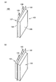
図13(A)に示すように、ラミネート型電池10は、図1(A)に示されたものと同じである。図13(B)に示すように、包囲部材20は、図1(B)に示されたものと同じである。図13(C)に示すように、固定箇所形成部材30は、図8(C)に示されたものと同じである。なお、包囲部材20の材料は、実施の形態1の包囲部材20と同様である。固定箇所形成部材30、31、32の材料は、実施の形態1の固定箇所形成部材31、32と同様である。
As shown in FIG. 13A, the
図14は、本発明の電池の実施の形態3を示す斜視図である。なお、図14においては、外装体14の熱溶着部141の図示は省略されている。
FIG. 14 is a perspective
図14に示すように、図13(A)で示されたラミネート型電池10の外装体14と固定箇所形成部材30の両者の外表面の一部を包囲するように、図13(B)に示された包囲部材20を配置する。そして、たとえば、包囲部材20が熱収縮性材料として厚みが30〜200μmのPETからなり、固定箇所形成部材30がポリカーボネートからなる場合、一例として120℃程度に加熱された雰囲気中に10秒間程度放置することにより、包囲部材20を収縮させることにより、外装体14と固定箇所形成部材30の両者の外表面の一部に接触させて、外装体14と包囲部材20と固定箇所形成部材30を一体化させる。この場合、包囲部材20は外装体14の中央部を覆い、両端部を露出するように配置されている。本体部35の両端と突出部36a、36b、36c、36dが包囲部材20の外側に突出するように配置されている。このようにして、包囲部材20が、外装体14と固定箇所形成部材30の両者の外表面の一部を包囲して、形状変化により外装体14と固定箇所形成部材30の両者の外表面の一部に接触して外装体14を保持することにより、本発明の実施の形態3として単一の形態として取り扱うことが可能な単位電池5が構成される。なお、固定箇所37a、37b、37c、37dが形成された突出部36a、36b、36c、36dは、図14に示すように一方向に折り曲げられていてもよい。
As shown in FIG. 14, as shown in FIG. 13B, a part of the outer surface of both the
以上のように構成された単位電池5では、上述した実施の形態2の単位電池3と同様の作用効果を達成することができるとともに、実施の形態2の単位電池3に比べて位置決め箇所や固定箇所を増やすことができる。
The unit battery 5 configured as described above can achieve the same effects as the
(実施形態4)
図15は、本発明の電池の実施の形態4を示す斜視図である。なお、図15においては、外装体14の熱溶着部141の図示は省略されている。
(Embodiment 4)
FIG. 15 is a perspective view showing Embodiment 4 of the battery of the present invention. In addition, in FIG. 15, illustration of the
図15に示すように、実施の形態4の単位電池6は、正極接続端子12と負極接続端子13が外装体14の同じ側から突出していること以外は、図2に示された実施の形態1の単位電池1と同じ構成である。このように構成された単位電池6では、上述した実施の形態1の単位電池1と同様の作用効果を達成することができるとともに、単位電池6を複数個組み合わせた場合、正極接続端子12と負極接続端子13が配列される単位電池6の側部が、固定箇所形成部材31、32が配列される単位電池6の側部に対して交差する、この例では直交するように配置されるので、組電池において、充放電のために正負極接続端子に接続される配線と、電池の位置決めや固定のための構成部材とを筐体内で配置するのに好適である。
As shown in FIG. 15, the
(実施形態5)
図16は、本発明の電池の実施の形態5を示す斜視図である。なお、図16においては、外装体14の熱溶着部141の図示は省略されている。
(Embodiment 5)
FIG. 16 is a perspective view showing Embodiment 5 of the battery of the present invention. In addition, in FIG. 16, illustration of the
図16に示すように、実施の形態5の単位電池7では、正極接続端子12と負極接続端子13が外装体14の互いに対向する両側部から突出するように配置されているが、包囲部材20には、正極接続端子12と負極接続端子13の各々に近い部分に切欠き26、27が形成されている。その他の構成は、図2に示された実施の形態1の単位電池1と同じ構成である。このように構成された単位電池7では、上述した実施の形態1の単位電池1と同様の作用効果を達成することができるとともに、素電池11で発生した熱を、切欠き26、27によって露出した外装体14の外表面から外側に放出することができるので、電池の放熱性を高めることができる。
As shown in FIG. 16, in the unit battery 7 of the fifth embodiment, the positive
(実施形態6)
図17は、本発明の電池の実施の形態6を示す斜視図である。なお、図17においては、外装体14の熱溶着部141の図示は省略されている。
(Embodiment 6)
FIG. 17 is a perspective
図17に示すように、実施の形態6の単位電池8では、正極接続端子12と負極接続端子13が外装体14の互いに対向する両側部から突出するように配置されているが、包囲部材20には、包囲部材20の外側から外装体14の外表面に到達する複数の貫通孔28が形成されている。その他の構成は、図2に示された実施の形態1の単位電池1と同じ構成である。このように構成された単位電池8では、上述した実施の形態1の単位電池1と同様の作用効果を達成することができるとともに、複数の貫通孔28を通じて、素電池11で発生した熱を外装体14の外表面から包囲部材20の外側に放出することができるので、電池の放熱性を高めることができる。
As shown in FIG. 17, in the
今回開示された実施の形態はすべての点で例示であって制限的なものではないと考慮されるべきである。本発明の範囲は以上の実施の形態ではなく、特許請求の範囲によって示され、特許請求の範囲と均等の意味および範囲内でのすべての修正や変形を含むものであることが意図される。 It should be considered that the embodiments disclosed herein are illustrative and non-restrictive in every respect. The scope of the present invention is shown not by the above embodiments but by the scope of the claims, and is intended to include all modifications and variations within the meaning and scope equivalent to the scope of the claims.
本発明の電池は、バックアップ電源として発電所や自宅用の電力貯蔵用バッテリーに用いられるだけでなく、自動車、二輪車、電車、カートなどの車両の動力源用バッテリーとして用いられるラミネート型電池に適用されるのが好ましく、特に激しい振動を伴うラミネート型電池に適している。 The battery of the present invention is applied not only to a power storage battery for power plants and homes as a backup power source, but also to a laminated battery used as a power source battery for vehicles such as automobiles, motorcycles, trains and carts. And is particularly suitable for laminated batteries with severe vibration.
1,3,5,6,7,8:単位電池、2,4:組電池、10:ラミネート型電池、11:素電池、12:正極接続端子、13:負極接続端子、14:外装体、141:熱溶着部、20:包囲部材、22,23:固定箇所形成部、24,25,33,34:固定箇所、26,27:切欠き、28:貫通孔、30,31,32:固定箇所形成部材、41,43:棒状部材。
1, 3, 5, 6, 7, 8: unit cell, 2, 4: assembled battery, 10: laminate type battery, 11: unit cell, 12: positive electrode connection terminal, 13: negative electrode connection terminal, 14: exterior body, 141: thermal welding part, 20: surrounding member, 22, 23: fixing part forming part, 24, 25, 33, 34: fixing part, 26, 27: notch, 28: through hole, 30, 31, 32: fixing
Claims (10)
前記外装体の外表面の少なくとも一部を包囲し、形状変化により前記外装体の外表面の少なくとも一部に接触して前記外装体を保持するようにされた包囲部材と、
を備えた電池。 An exterior body made of a flexible film containing the unit cells;
An enclosing member that surrounds at least a part of the outer surface of the exterior body and is configured to hold the exterior body in contact with at least a portion of the outer surface of the exterior body by a shape change;
With battery.
前記複数の外装体の外表面の少なくとも一部を包囲して、形状変化により前記複数の外装体の外表面の少なくとも一部に接触して前記複数の外装体を保持するようにされた包囲部材と、
を備えた電池。 A plurality of exterior bodies each made of a flexible film containing a unit cell;
An enclosing member that surrounds at least a part of the outer surfaces of the plurality of exterior bodies and contacts the at least a part of the outer surfaces of the plurality of exterior bodies by a shape change to hold the plurality of exterior bodies. When,
With battery.
前記包囲部材には、前記正極接続端子または前記負極接続端子の少なくともいずれかに近い部分に切欠きが形成されている、請求項1から請求項4までのいずれか1項に記載の電池。 A positive connection terminal and a negative connection terminal that are electrically connected to each of the positive electrode and the negative electrode of the unit cell and extend from the exterior body;
The battery according to any one of claims 1 to 4, wherein the surrounding member has a notch formed in a portion close to at least one of the positive electrode connecting terminal and the negative electrode connecting terminal.
前記包囲部材が前記正極接続端子および前記負極接続端子の延びる方向に沿って延在する長さは、前記外装体の長さよりも短い、請求項1から請求項5までのいずれか1項に記載の電池。 A positive connection terminal and a negative connection terminal that are electrically connected to each of the positive electrode and the negative electrode of the unit cell and extend from the exterior body;
6. The length of the surrounding member extending along the extending direction of the positive electrode connection terminal and the negative electrode connection terminal is shorter than the length of the exterior body, according to claim 1. Battery.
前記第1の固定箇所形成部材は前記包囲部材の外表面に固着されている、請求項1から請求項6までのいずれか1項に記載の電池。 A first fixing portion forming member formed with a fixing portion used for fixing the battery to another member;
The battery according to any one of claims 1 to 6, wherein the first fixing portion forming member is fixed to an outer surface of the surrounding member.
前記包囲部材は、前記外装体と前記第2の固定箇所形成部材の両者の外表面の一部を包囲して、形状変化により前記外装体と前記第2の固定箇所形成部材の両者の外表面の一部に接触して前記外装体を保持するようにされている、請求項1から請求項8までのいずれか1項に記載の電池。 A second fixing portion forming member formed with a fixing portion used for fixing the battery to another member;
The surrounding member surrounds a part of the outer surface of both the exterior body and the second fixed location forming member, and the outer surface of both the exterior body and the second fixed location forming member by shape change The battery according to claim 1, wherein the battery is held in contact with a part of the battery.
Priority Applications (1)
| Application Number | Priority Date | Filing Date | Title |
|---|---|---|---|
| JP2008226565A JP2010061998A (en) | 2008-09-04 | 2008-09-04 | Battery, and battery pack |
Applications Claiming Priority (1)
| Application Number | Priority Date | Filing Date | Title |
|---|---|---|---|
| JP2008226565A JP2010061998A (en) | 2008-09-04 | 2008-09-04 | Battery, and battery pack |
Publications (1)
| Publication Number | Publication Date |
|---|---|
| JP2010061998A true JP2010061998A (en) | 2010-03-18 |
Family
ID=42188577
Family Applications (1)
| Application Number | Title | Priority Date | Filing Date |
|---|---|---|---|
| JP2008226565A Pending JP2010061998A (en) | 2008-09-04 | 2008-09-04 | Battery, and battery pack |
Country Status (1)
| Country | Link |
|---|---|
| JP (1) | JP2010061998A (en) |
Cited By (13)
| Publication number | Priority date | Publication date | Assignee | Title |
|---|---|---|---|---|
| JP2010067422A (en) * | 2008-09-10 | 2010-03-25 | Murata Mfg Co Ltd | Battery and battery pack |
| JP2011249327A (en) * | 2010-05-21 | 2011-12-08 | Dr Ing Hcf Porsche Ag | Pouch cell battery device, and manufacturing method and usage thereof |
| JP2012076571A (en) * | 2010-09-30 | 2012-04-19 | Honda Motor Co Ltd | Battery module mounting structure for electric motorcycle |
| KR101146675B1 (en) * | 2010-08-09 | 2012-05-23 | 삼성에스디아이 주식회사 | Battery Pack |
| WO2014087836A1 (en) * | 2012-12-06 | 2014-06-12 | 株式会社村田製作所 | Battery and battery pack using same |
| WO2014087837A1 (en) * | 2012-12-06 | 2014-06-12 | 株式会社村田製作所 | Battery and battery pack using same |
| WO2017026145A1 (en) * | 2015-08-07 | 2017-02-16 | 株式会社Ihi | Cell module |
| JP2018537834A (en) * | 2016-06-09 | 2018-12-20 | エルジー・ケム・リミテッド | Secondary battery |
| JP6472032B1 (en) * | 2017-10-26 | 2019-02-20 | セイコーインスツル株式会社 | Electrochemical cell |
| DE102019103870B3 (en) * | 2019-02-15 | 2020-02-27 | Dr. Ing. H.C. F. Porsche Aktiengesellschaft | battery |
| JP2021510001A (en) * | 2018-07-03 | 2021-04-08 | エルジー・ケム・リミテッド | Battery module with heat shrinkable tube |
| WO2021258924A1 (en) * | 2020-06-23 | 2021-12-30 | 曙鹏科技(深圳)有限公司 | Button-type pouch battery cell and button battery |
| US11777177B2 (en) | 2018-02-15 | 2023-10-03 | Nippon Telegraph And Telephone Corporation | Assembled battery |
Citations (3)
| Publication number | Priority date | Publication date | Assignee | Title |
|---|---|---|---|---|
| JP2000090897A (en) * | 1998-09-17 | 2000-03-31 | Japan Storage Battery Co Ltd | Battery and battery pack |
| JP2002100326A (en) * | 2000-09-22 | 2002-04-05 | Gs-Melcotec Co Ltd | Flat-type battery |
| JP2004047334A (en) * | 2002-07-12 | 2004-02-12 | Nissan Motor Co Ltd | Battery pack |
-
2008
- 2008-09-04 JP JP2008226565A patent/JP2010061998A/en active Pending
Patent Citations (3)
| Publication number | Priority date | Publication date | Assignee | Title |
|---|---|---|---|---|
| JP2000090897A (en) * | 1998-09-17 | 2000-03-31 | Japan Storage Battery Co Ltd | Battery and battery pack |
| JP2002100326A (en) * | 2000-09-22 | 2002-04-05 | Gs-Melcotec Co Ltd | Flat-type battery |
| JP2004047334A (en) * | 2002-07-12 | 2004-02-12 | Nissan Motor Co Ltd | Battery pack |
Cited By (18)
| Publication number | Priority date | Publication date | Assignee | Title |
|---|---|---|---|---|
| JP2010067422A (en) * | 2008-09-10 | 2010-03-25 | Murata Mfg Co Ltd | Battery and battery pack |
| US9048463B2 (en) | 2010-05-21 | 2015-06-02 | Dr. Ing. H.C. F. Porsche Aktiengesellschaft | Pouch-cell battery arrangement and corresponding production method and use |
| JP2011249327A (en) * | 2010-05-21 | 2011-12-08 | Dr Ing Hcf Porsche Ag | Pouch cell battery device, and manufacturing method and usage thereof |
| KR101146675B1 (en) * | 2010-08-09 | 2012-05-23 | 삼성에스디아이 주식회사 | Battery Pack |
| US9099712B2 (en) | 2010-08-09 | 2015-08-04 | Samsung Sdi Co., Ltd. | Battery pack |
| JP2012076571A (en) * | 2010-09-30 | 2012-04-19 | Honda Motor Co Ltd | Battery module mounting structure for electric motorcycle |
| JPWO2014087837A1 (en) * | 2012-12-06 | 2017-01-05 | 株式会社村田製作所 | Battery and assembled battery using the same |
| WO2014087837A1 (en) * | 2012-12-06 | 2014-06-12 | 株式会社村田製作所 | Battery and battery pack using same |
| WO2014087836A1 (en) * | 2012-12-06 | 2014-06-12 | 株式会社村田製作所 | Battery and battery pack using same |
| WO2017026145A1 (en) * | 2015-08-07 | 2017-02-16 | 株式会社Ihi | Cell module |
| JP2018537834A (en) * | 2016-06-09 | 2018-12-20 | エルジー・ケム・リミテッド | Secondary battery |
| JP6472032B1 (en) * | 2017-10-26 | 2019-02-20 | セイコーインスツル株式会社 | Electrochemical cell |
| JP2019079744A (en) * | 2017-10-26 | 2019-05-23 | セイコーインスツル株式会社 | Electrochemical cell |
| US11777177B2 (en) | 2018-02-15 | 2023-10-03 | Nippon Telegraph And Telephone Corporation | Assembled battery |
| JP2021510001A (en) * | 2018-07-03 | 2021-04-08 | エルジー・ケム・リミテッド | Battery module with heat shrinkable tube |
| JP7047208B2 (en) | 2018-07-03 | 2022-04-05 | エルジー エナジー ソリューション リミテッド | Battery module with heat shrinkable tube |
| DE102019103870B3 (en) * | 2019-02-15 | 2020-02-27 | Dr. Ing. H.C. F. Porsche Aktiengesellschaft | battery |
| WO2021258924A1 (en) * | 2020-06-23 | 2021-12-30 | 曙鹏科技(深圳)有限公司 | Button-type pouch battery cell and button battery |
Similar Documents
| Publication | Publication Date | Title |
|---|---|---|
| JP2010061998A (en) | Battery, and battery pack | |
| JP5374979B2 (en) | Batteries and batteries | |
| JP4858726B2 (en) | Secondary battery holding structure | |
| KR100767911B1 (en) | Battery pack | |
| JP5067171B2 (en) | Electrochemical storage element module | |
| JP5113319B2 (en) | Storage cell package structure | |
| KR101509474B1 (en) | Battery Assembly Having Single Electrode Terminal Connecting Part | |
| JP5260565B2 (en) | Secondary battery | |
| US20120082887A1 (en) | Electrical storage unit | |
| KR102058194B1 (en) | battery module | |
| KR102018693B1 (en) | Rechargeable battery pack | |
| KR20070112489A (en) | Middle or large-sized battery module | |
| US20220037722A1 (en) | Battery Cell and Battery Module Including the Same | |
| KR101841663B1 (en) | Battery Module Having Voltage Sensing Member with Receptacle Structure | |
| US20150050523A1 (en) | Battery pack | |
| JP5098318B2 (en) | Battery module | |
| JP2009266653A (en) | Battery pack | |
| US20130323566A1 (en) | Thin secondary battery | |
| JP4461940B2 (en) | Assembled battery | |
| JP2021118174A (en) | Battery module | |
| WO2016067487A1 (en) | Power supply device | |
| JP2008159328A (en) | Battery module | |
| JP2006196222A (en) | Battery cell assembly, battery pack structure, and its assembling method | |
| JP5229511B2 (en) | Secondary battery holding structure | |
| JP2015026424A (en) | Power storage module |
Legal Events
| Date | Code | Title | Description |
|---|---|---|---|
| A621 | Written request for application examination |
Free format text: JAPANESE INTERMEDIATE CODE: A621 Effective date: 20110819 |
|
| A977 | Report on retrieval |
Free format text: JAPANESE INTERMEDIATE CODE: A971007 Effective date: 20130225 |
|
| A131 | Notification of reasons for refusal |
Free format text: JAPANESE INTERMEDIATE CODE: A131 Effective date: 20130305 |
|
| A02 | Decision of refusal |
Free format text: JAPANESE INTERMEDIATE CODE: A02 Effective date: 20130702 |