WO2017026145A1 - Cell module - Google Patents
Cell module Download PDFInfo
- Publication number
- WO2017026145A1 WO2017026145A1 PCT/JP2016/062609 JP2016062609W WO2017026145A1 WO 2017026145 A1 WO2017026145 A1 WO 2017026145A1 JP 2016062609 W JP2016062609 W JP 2016062609W WO 2017026145 A1 WO2017026145 A1 WO 2017026145A1
- Authority
- WO
- WIPO (PCT)
- Prior art keywords
- battery cell
- engagement
- battery
- battery module
- reinforcing plate
- Prior art date
Links
Images


Classifications
-
- H—ELECTRICITY
- H01—ELECTRIC ELEMENTS
- H01M—PROCESSES OR MEANS, e.g. BATTERIES, FOR THE DIRECT CONVERSION OF CHEMICAL ENERGY INTO ELECTRICAL ENERGY
- H01M10/00—Secondary cells; Manufacture thereof
- H01M10/60—Heating or cooling; Temperature control
- H01M10/61—Types of temperature control
- H01M10/613—Cooling or keeping cold
-
- H—ELECTRICITY
- H01—ELECTRIC ELEMENTS
- H01M—PROCESSES OR MEANS, e.g. BATTERIES, FOR THE DIRECT CONVERSION OF CHEMICAL ENERGY INTO ELECTRICAL ENERGY
- H01M10/00—Secondary cells; Manufacture thereof
- H01M10/60—Heating or cooling; Temperature control
- H01M10/64—Heating or cooling; Temperature control characterised by the shape of the cells
- H01M10/647—Prismatic or flat cells, e.g. pouch cells
-
- H—ELECTRICITY
- H01—ELECTRIC ELEMENTS
- H01M—PROCESSES OR MEANS, e.g. BATTERIES, FOR THE DIRECT CONVERSION OF CHEMICAL ENERGY INTO ELECTRICAL ENERGY
- H01M10/00—Secondary cells; Manufacture thereof
- H01M10/60—Heating or cooling; Temperature control
- H01M10/65—Means for temperature control structurally associated with the cells
- H01M10/653—Means for temperature control structurally associated with the cells characterised by electrically insulating or thermally conductive materials
-
- H—ELECTRICITY
- H01—ELECTRIC ELEMENTS
- H01M—PROCESSES OR MEANS, e.g. BATTERIES, FOR THE DIRECT CONVERSION OF CHEMICAL ENERGY INTO ELECTRICAL ENERGY
- H01M10/00—Secondary cells; Manufacture thereof
- H01M10/60—Heating or cooling; Temperature control
- H01M10/65—Means for temperature control structurally associated with the cells
- H01M10/655—Solid structures for heat exchange or heat conduction
- H01M10/6551—Surfaces specially adapted for heat dissipation or radiation, e.g. fins or coatings
-
- H—ELECTRICITY
- H01—ELECTRIC ELEMENTS
- H01M—PROCESSES OR MEANS, e.g. BATTERIES, FOR THE DIRECT CONVERSION OF CHEMICAL ENERGY INTO ELECTRICAL ENERGY
- H01M10/00—Secondary cells; Manufacture thereof
- H01M10/60—Heating or cooling; Temperature control
- H01M10/65—Means for temperature control structurally associated with the cells
- H01M10/655—Solid structures for heat exchange or heat conduction
- H01M10/6554—Rods or plates
- H01M10/6555—Rods or plates arranged between the cells
-
- H—ELECTRICITY
- H01—ELECTRIC ELEMENTS
- H01M—PROCESSES OR MEANS, e.g. BATTERIES, FOR THE DIRECT CONVERSION OF CHEMICAL ENERGY INTO ELECTRICAL ENERGY
- H01M50/00—Constructional details or processes of manufacture of the non-active parts of electrochemical cells other than fuel cells, e.g. hybrid cells
- H01M50/20—Mountings; Secondary casings or frames; Racks, modules or packs; Suspension devices; Shock absorbers; Transport or carrying devices; Holders
- H01M50/204—Racks, modules or packs for multiple batteries or multiple cells
- H01M50/207—Racks, modules or packs for multiple batteries or multiple cells characterised by their shape
- H01M50/211—Racks, modules or packs for multiple batteries or multiple cells characterised by their shape adapted for pouch cells
-
- H—ELECTRICITY
- H01—ELECTRIC ELEMENTS
- H01M—PROCESSES OR MEANS, e.g. BATTERIES, FOR THE DIRECT CONVERSION OF CHEMICAL ENERGY INTO ELECTRICAL ENERGY
- H01M50/00—Constructional details or processes of manufacture of the non-active parts of electrochemical cells other than fuel cells, e.g. hybrid cells
- H01M50/20—Mountings; Secondary casings or frames; Racks, modules or packs; Suspension devices; Shock absorbers; Transport or carrying devices; Holders
- H01M50/218—Mountings; Secondary casings or frames; Racks, modules or packs; Suspension devices; Shock absorbers; Transport or carrying devices; Holders characterised by the material
- H01M50/22—Mountings; Secondary casings or frames; Racks, modules or packs; Suspension devices; Shock absorbers; Transport or carrying devices; Holders characterised by the material of the casings or racks
- H01M50/222—Inorganic material
- H01M50/224—Metals
-
- H—ELECTRICITY
- H01—ELECTRIC ELEMENTS
- H01M—PROCESSES OR MEANS, e.g. BATTERIES, FOR THE DIRECT CONVERSION OF CHEMICAL ENERGY INTO ELECTRICAL ENERGY
- H01M50/00—Constructional details or processes of manufacture of the non-active parts of electrochemical cells other than fuel cells, e.g. hybrid cells
- H01M50/20—Mountings; Secondary casings or frames; Racks, modules or packs; Suspension devices; Shock absorbers; Transport or carrying devices; Holders
- H01M50/233—Mountings; Secondary casings or frames; Racks, modules or packs; Suspension devices; Shock absorbers; Transport or carrying devices; Holders characterised by physical properties of casings or racks, e.g. dimensions
- H01M50/242—Mountings; Secondary casings or frames; Racks, modules or packs; Suspension devices; Shock absorbers; Transport or carrying devices; Holders characterised by physical properties of casings or racks, e.g. dimensions adapted for protecting batteries against vibrations, collision impact or swelling
-
- H—ELECTRICITY
- H01—ELECTRIC ELEMENTS
- H01M—PROCESSES OR MEANS, e.g. BATTERIES, FOR THE DIRECT CONVERSION OF CHEMICAL ENERGY INTO ELECTRICAL ENERGY
- H01M50/00—Constructional details or processes of manufacture of the non-active parts of electrochemical cells other than fuel cells, e.g. hybrid cells
- H01M50/20—Mountings; Secondary casings or frames; Racks, modules or packs; Suspension devices; Shock absorbers; Transport or carrying devices; Holders
- H01M50/289—Mountings; Secondary casings or frames; Racks, modules or packs; Suspension devices; Shock absorbers; Transport or carrying devices; Holders characterised by spacing elements or positioning means within frames, racks or packs
- H01M50/291—Mountings; Secondary casings or frames; Racks, modules or packs; Suspension devices; Shock absorbers; Transport or carrying devices; Holders characterised by spacing elements or positioning means within frames, racks or packs characterised by their shape
-
- H—ELECTRICITY
- H01—ELECTRIC ELEMENTS
- H01M—PROCESSES OR MEANS, e.g. BATTERIES, FOR THE DIRECT CONVERSION OF CHEMICAL ENERGY INTO ELECTRICAL ENERGY
- H01M50/00—Constructional details or processes of manufacture of the non-active parts of electrochemical cells other than fuel cells, e.g. hybrid cells
- H01M50/20—Mountings; Secondary casings or frames; Racks, modules or packs; Suspension devices; Shock absorbers; Transport or carrying devices; Holders
- H01M50/289—Mountings; Secondary casings or frames; Racks, modules or packs; Suspension devices; Shock absorbers; Transport or carrying devices; Holders characterised by spacing elements or positioning means within frames, racks or packs
- H01M50/293—Mountings; Secondary casings or frames; Racks, modules or packs; Suspension devices; Shock absorbers; Transport or carrying devices; Holders characterised by spacing elements or positioning means within frames, racks or packs characterised by the material
-
- Y—GENERAL TAGGING OF NEW TECHNOLOGICAL DEVELOPMENTS; GENERAL TAGGING OF CROSS-SECTIONAL TECHNOLOGIES SPANNING OVER SEVERAL SECTIONS OF THE IPC; TECHNICAL SUBJECTS COVERED BY FORMER USPC CROSS-REFERENCE ART COLLECTIONS [XRACs] AND DIGESTS
- Y02—TECHNOLOGIES OR APPLICATIONS FOR MITIGATION OR ADAPTATION AGAINST CLIMATE CHANGE
- Y02E—REDUCTION OF GREENHOUSE GAS [GHG] EMISSIONS, RELATED TO ENERGY GENERATION, TRANSMISSION OR DISTRIBUTION
- Y02E60/00—Enabling technologies; Technologies with a potential or indirect contribution to GHG emissions mitigation
- Y02E60/10—Energy storage using batteries
Definitions
- the present disclosure relates to a battery module.
- Priority is claimed on Japanese Patent Application No. 2015-157769, filed Aug. 7, 2015, the content of which is incorporated herein by reference.
- Patent Document 1 includes a pressure holder that holds a flat battery cell in a sandwiching manner, and holds the pressure state of the battery cell by fastening the pressure holder from both sides with a fastening bolt and a fastening nut.
- a battery module is disclosed.
- the present disclosure is made in view of the above-described problems, and aims to miniaturize a battery module by enabling the battery cell to be held in a pressurized state without using a bolt and a nut.
- the present disclosure adopts the following configuration as means for solving the above problems.
- a first aspect according to the present disclosure is a battery module having a plurality of flat battery cells stacked and a housing in which the battery cells are accommodated, the housing including an engagement claw on a side wall portion. And a second part having an engagement hole in which the battery cell is disposed between the first part and the first part and the engagement claw of the first part is engaged.
- the battery module is disposed between the first part and the container-like first part having the engagement claw in the side wall portion of the casing of the battery module, and the engagement claw of the first part And a second part having an engagement hole to be engaged. For this reason, it is possible to fix the first part and the second part by engaging the engagement claws with the engagement holes. As a result, the battery cell can be held between the first part and the second part and held in a pressurized state. Therefore, the battery cell can be held in a pressurized state without using a bolt and a nut, and the battery module can be miniaturized.
- FIG. 1 is an exploded perspective view of a battery module according to an embodiment of the present disclosure.
- FIG. 2 is a cross-sectional view taken along line AA of FIG.
- FIG. 7 is a view showing a welding position of a reinforcing plate in an embodiment of the present disclosure.
- It is a perspective view showing the example of the lower part which served as the lower case concerning the present disclosure.
- It is a perspective view showing the example of the lower part which served as the lower case concerning the present disclosure.
- It is a perspective view which shows the example of an engaging plate.
- It is a perspective view showing an example of upper parts corresponding to a lower part concerning this indication.
- It is a perspective view which shows the example of the upper case applied to this indication.
- It is a perspective view which shows the example of the upper case applied to this indication.
- FIG. 1 is a perspective view of a battery module according to an embodiment of the present disclosure
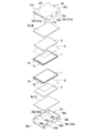
- FIG. 2 is an exploded perspective view of the battery module according to an embodiment of the present disclosure.
- the battery module of the present embodiment is a module of a lithium ion secondary battery, and as shown in FIG. 2, has a battery cell 1, a buffer material 2, a housing 3, and a reinforcing plate 4.
- the battery cell 1 is a cell of a flat plate type laminate type lithium ion secondary battery formed by laminating a thin positive electrode plate and a thin negative electrode plate with a separator interposed therebetween and laminating the whole.
- the battery module of the present embodiment is used as a large-capacity battery by stacking a plurality of such battery cells 1.
- the battery cell 1 has the electrode 1a in the edge part.
- the electrode 1a is an electrode for connecting to the outside. Charging / discharging of the battery cell 1 is performed via this electrode 1a.
- the shock absorbing material 2 equalizes the pressure applied to the battery cell 1, and further absorbs deformation of the battery cell 1 caused by the impact and heat generation and the like that the battery cell 1 receives due to the vibration of the battery module, etc. It is a board formed of a material. Such a buffer material 2 is disposed to sandwich the battery cells 1 one by one from the front and back, and is disposed between the battery cells 1 and between the battery cells 1 and the reinforcing plate 4. That is, in the housing 3, the battery cells 1 and the buffer material 2 are arranged to be alternately stacked. Moreover, it is preferable to make the heat conductivity of the buffer material 2 higher than the battery cell 1 by using the material excellent in heat conductivity for the buffer material 2. Thereby, the heat generated in the battery cell 1 can be efficiently released to the outside through the buffer material 2.
- a heat dissipation sheet S having thermal conductivity higher than that of the battery cell 1 may be disposed between the battery cell 1 and the buffer material 2.
- the heat-radiating sheet S needs to be at least as deformable as the shock absorbing material 2 so as not to affect the function of the shock absorbing material 2 described above.
- the heat dissipating sheet S is excellent in thermal conductivity and can be deformed, and the heat dissipating sheet S is laminated between the battery cell 1 and the buffer material 2 Do.
- the heat generated in the battery cell 1 can be efficiently released to the outside through the heat dissipation sheet S.
- the casing 3 is made of a material having good heat conductivity such as aluminum. Therefore, the heat transmitted from the battery cell 1 to the shock absorbing material 2 and the heat dissipation sheet S can be further reduced by bringing the end portions of the shock absorbing material 2 and the heat dissipation sheet S into contact with the housing 3. It is possible to transmit from the end portion to the housing 3 and to discharge it from the housing 3 to the outside more efficiently. For example, in FIG.
- the end surface 2 a of the shock absorbing material 2 is in contact with the side surface portion 30 a of the lower part 30 constituting the housing 3 from the inside.
- the heat generated in the battery cell 1 can be transmitted to the housing 3 through the end face 2 a of the buffer material 2, and can be released from the housing 3 to the outside more efficiently.
- FIG. 3 is a cross-sectional view taken along line AA of FIG.
- the housing 3 is a rectangular solid container made of metal such as aluminum that is resistant to an impact such as internal pressure or vibration and has good heat conductivity, and accommodates the battery cell 1.
- a housing 3 includes a lower part 30 (first part) and an upper part 31 (second part), and sandwiches the battery cell 1 and the buffer material 2 between the lower part 30 and the upper part 31 in the stacking direction.
- the battery cell 1 is held while being pressurized.
- an opening is formed in a part of the side surface of the housing 3, and the electrode 1 a protrudes to the outside of the housing 3 from the opening.
- the lower part 30 is a container-like (specifically, a rectangular parallelepiped opening upward) having a side surface 30a formed of three surfaces and a bottom surface 30b closing the lower end of the side surface 30a.
- the lower part 30 has engaging claws 30e on the right side wall 30c and the left side wall 30d, which are surfaces facing each other across the bottom surface 30b among the three surfaces of the side surface 30a.
- the engagement claws 30e are projections formed at three equal intervals on each of the right side wall 30c and the left side wall 30d. Further, the engaging claws 30e formed on the right side wall 30c and the engaging claws 30e formed on the left side wall 30d are axisymmetrically opposed to each other across the bottom surface 30b (ie, opposed to each other across the bottom surface 30b) In position). Furthermore, as shown in FIG. 3, the engaging claw 30e has a substantially triangular cross section having an inclined surface 30f spreading outward toward the bottom surface 30b and a horizontal portion 30g parallel to the bottom surface 30b. I am
- the upper part 31 is a part that covers the lower part 30 from the upper side, and has a side surface portion 31a formed of three wall portions and an upper surface portion 31b that covers the upper side of the side surface portion 31a.
- Such an upper part 31 has an engagement hole 31e in each of the right side wall 31c and the left side wall 31d, which are two surfaces facing each other across the upper surface 31b among the three surfaces of the side surface 31a. .
- the engagement hole 31 e is a rectangular opening formed in the right side wall 31 c and the left side wall 31 d.
- the engagement holes 31e are formed in three places at equal intervals corresponding to the positions of the engagement claws 30e in order to engage the engagement claws 30e, and like the engagement claws 30e, the right side wall
- the engagement holes 31e formed in the portion 31c and the engagement holes 31e formed in the left side wall portion 31d are provided in line symmetry with the upper surface portion 31b interposed therebetween.
- a reinforcing portion 31f is formed to be bent so as to overlap the upper surface of the upper surface portion 31b.
- the reinforcing portion 31 f prevents the deformation of the upper part 31 when the lower part 30 and the upper part 31 sandwich and hold the battery cell 1 while holding it.
- the reinforcing plate 4 is a metal plate member interposed between the housing 3 and the battery cell 1 in order to prevent the housing 3 from being deformed due to expansion of the battery cell 1.
- a bottom reinforcing plate 4a and an upper reinforcing plate 4b are provided as the reinforcing plate 4.
- the lower surface of the bottom side reinforcing plate 4 a is fixed to the bottom surface portion 30 b by spot welding, and the upper surface is in contact with the cushioning material 2 over the entire surface.
- the bottom side reinforcing plate 4 a is interposed between the lower part 30 and the battery cell 1 via the cushioning material 2. Further, the bottom side reinforcing plate 4 a covers the entire area of the battery cell 1 as viewed from the stacking direction of the battery cell 1. Further, the contact surface of the bottom side reinforcing plate 4a in contact with the shock absorbing material 2 is a flat surface without any unevenness.
- FIG. 4 is a view showing a welding position of the reinforcing plate 4 in the present embodiment.
- the bottom reinforcing plate 4a is spot-welded to the lower part 30 at a welding point X provided on the straight line B.
- the straight line B indicates that the two opposing engaging claws 30e disposed on the side closest to the opening of the side surface portion 30a when viewed from the stacking direction of the battery cells 1 face each other, which is disposed second from the opening It is three straight lines respectively connecting the two engaging claws 30e to each other and the engaging claws 30e disposed on the side farthest from the opening.
- Three welding points X are provided at equal intervals on each straight line B. That is, the bottom side reinforcing plate 4a welded to the lower part 30 at a plurality of places (9 places in FIG. 4) in this way prevents the bottom part 30b from being deformed, and further the deformation of the whole lower part 30 To prevent.
- the upper surface of the upper reinforcing plate 4 b is fixed to the upper surface portion 31 b, and the lower surface is in contact with the buffer material 2 over the entire surface. Similar to the bottom side reinforcing plate 4 a, the upper side reinforcing plate 4 b is interposed between the upper part 31 and the battery cell 1 via the cushioning material 2. Further, the upper reinforcing plate 4 b covers the entire area of the battery cell 1 as viewed from the stacking direction of the battery cell 1.
- the contact surface of the upper reinforcing plate 4b in contact with the cushioning material 2 is a flat surface without unevenness.
- the upper reinforcing plate 4 b is spot-welded at a welding point Y on the straight line C.
- the straight line C indicates that the two opposing engagement holes 31e disposed on the side closest to the opening of the side surface portion 31a as viewed in the stacking direction of the battery cells 1 face each other, which is disposed second from the opening It is three straight lines respectively connecting the two engaging holes 31e to each other and the engaging holes 31e arranged on the side farthest from the opening.
- the straight line C is viewed from the stacking direction of the battery cell 1, and the two opposing two lines disposed closest to each other from the opening of the side surface 30 a It is three straight lines respectively connecting the engaging claws 30e, two opposingly disposed second engaging claws 30e, and the engaging claws 30e disposed at the far end.
- the welding points Y are provided at three positions at equal intervals on each straight line C. That is, the upper reinforcing plate 4b welded to the upper part 31 at a plurality of places (9 places in FIG. 4) in this way prevents the upper face part 31b from being deformed, and further, the deformation of the entire upper part 31 is To prevent.
- the bottom side reinforcing plate 4a is previously joined to the lower part 30 by spot welding, and the upper side reinforcing plate 4b is joined to the upper part 31 by spot welding.
- the buffer material 2 and the battery cell 1 are alternately stacked and disposed on the bottom side reinforcing plate 4 a joined to the lower part 30.
- the height of the laminate of the buffer material 2 and the battery cell 1 is a height projecting upward from the side surface portion 30 a of the lower part 30.
- the upper part 31 is placed on the upper part 31 from the upper side of the lower part 30 where the laminate of the buffer material 2 and the battery cell 1 is arranged, and the laminate of the buffer material 2 and the battery cell 1 is compressed. Push it down.
- the side surface portion 31 a of the upper part 31 is disposed outside the side surface portion 30 a of the lower part 30.
- the right side wall 31 c and the left side wall 31 d of the upper part 31 are elastically deformed in the direction of spreading outward by being guided along the inclined surface 30 f of the engagement claw 30 e of the lower part 30.
- the engagement claws 30e are inserted into the engagement holes 31e from the inside.
- the right side wall 31 c and the left side wall 31 d of the upper part 31 are restored to the original shape, and the engagement claws 30 e of the lower part 30 are engaged with the upper part 31.
- the lower part 30 and the upper part 31 are fixed by the horizontal portion 30g of the engagement claw 30e being hooked on the lower edge of the engagement hole 31e.
- the laminate of the buffer material 2 and the battery cell 1 is the lower part 30 and the upper part 31 from the stacking direction of the battery cell 1. And held in a pressurized state.
- the battery cell 1 is disposed between the lower part 30 and the lower part 30 having the engagement claws 30e on the right side wall 30c and the left side wall 30d. It has the upper part 31 which has the engagement hole 31e which is arrange
- the lower part 30 and the upper part 31 are fixed by inserting and engaging the engagement claw 30e into the engagement hole 31e. As a result, when the battery cell 1 is expanded and the force for pushing up the upper part 31 is applied, the engagement claw 30e is caught in the engagement hole 31e, so the upper part 31 is not removed. Therefore, it is possible to hold the battery cell 1 in a pressurized state without using a bolt and a nut.
- the reinforcing plate 4 interposed between the lower part 30 and the upper part 31 and the battery cell 1 is provided.
- the reinforcing plate 4 can receive the expansion force of the battery cell 1, and the deformation of the lower part 30 and the upper part 31 can be prevented.
- the reinforcement plate 4 covers the whole area of the battery cell 1 seeing from the lamination direction of the battery cell 1, and the surface (contact surface) is made flat.
- the entire surface of the battery cell 1 can be suppressed via the reinforcing plate 4 and the buffer material 2, and the entire surface of the battery cell 1 can be uniformly pressurized.
- the buffer material 2 is elastically deformable, the buffer material 2 elastically deforms, and in addition to pressing the battery cell 1 evenly, the shock received by the battery cell 1 due to the vibration of the battery module, etc. It is possible to absorb the deformation of the battery cell 1 caused by heat generation and the like.
- the reinforcing plate 4 includes the engaging claw 30e formed on the right side wall 30c and the engaging claw 30e formed on the symmetrical left side wall 30d. Spot welding is performed at a welding point overlapping with the straight line B connected.
- the portions around the engaging claws 30e and the engaging holes 31e are concentrated in stress, but by providing welding points (that is, welding spots) in the vicinity of these portions, the reinforcing plate 4 due to the above stress Peeling between the lower part 30 and the upper part 31 can be prevented.
- the housing 3 and the reinforcing plate 4 are made of metal with good thermal conductivity, the heat generated in the battery cell 1 is efficiently obtained through the housing 3 and the reinforcing plate 4 It can be released to the outside well. Furthermore, since the end face 2 a of the shock absorbing material 2 is in contact with the side surface portion 30 a of the lower part 30 constituting the housing 3 from the inside, the heat generated in the battery cell 1 is through the end face 2 a of the shock absorbing material 2 It can be transmitted to the housing 3 and released from the housing 3 to the outside more efficiently.
- the battery module is configured to include the reinforcing plate 4 in the above embodiment, the present disclosure is not limited thereto.
- the lower part 30 and the upper part 31 in which ribs are formed on the outer surface may be provided.
- the reinforcing plate 4 is not required, so the battery module according to the present embodiment can be maintained while maintaining the strength of the bottom surface portion 30b and the upper surface portion 31b. It is possible to reduce the weight in comparison.
- lower part 30 set it as the 1st part which has the engaging claw 30e and upper part 31 set it as the 2nd part which has the engagement hole 31e
- the upper part according to the present disclosure may be a first part having an engagement claw
- the lower part may be a second part having an engagement hole.
- the battery module is used by being housed in a case divided into two vertically.
- the lower case (hereinafter referred to as the lower case) may also be used as the lower part of the housing 3.
- the lower case doubles as the lower part of the housing 3
- members having the same functions as the members shown in FIGS. 1 to 4 are denoted by the same reference numerals as the members shown in FIGS. 1 to 4, and the description and illustration thereof will be omitted.
- FIG. 5A is a perspective view showing an example of the lower part 32 which doubles as the lower case.
- the lower part 32 shown in FIG. 5A is a container-like part (specifically, a rectangular solid opened upward) having a side surface part 32a consisting of three faces and a bottom surface part 32b closing the lower end of the side surface part 32a. It is made of metal such as aluminum. Then, the battery cell 1 and the buffer material 2 are sandwiched between the lower part 32 and the upper part described later in the stacking direction, and the battery cell 1 is held while being pressurized. Further, reference numeral 32 c is an opening formed in a part of the side surface of the lower part 32 in order to cause the electrode 1 a of the battery cell 1 to protrude out of the housing 3.
- the lower part 32 has engagement holes 32f in the right side wall 32d and the left side wall 32e which are surfaces facing each other across the bottom surface 32b among the three surfaces of the side surface 32a.
- the engagement holes 32f are rectangular openings formed at two equal intervals in each of the right side wall 32d and the left side wall 32e. Further, the engagement holes 32f formed in the right side wall 32d and the engagement holes 32f formed in the left side wall 32e are formed in line symmetry with respect to the bottom face 32b. Further, similarly to the lower part 30 shown in FIGS. 1 to 4, the bottom side reinforcing plate 4a is joined to the bottom surface part 32b of the lower part 32 by spot welding.
- the lower part 32 also functions as a lower case for housing the battery module. Therefore, screw holes 32h for fixing an upper case (hereinafter referred to as an upper case) to be described later are provided at positions corresponding to the four corners of the rectangular parallelepiped formed by the lower part 32 in the upper end surface 32g of the side surface portion 32a. Each is formed.
- FIG. 5B is a perspective view showing an example in the case where the side part 32a does not have the engagement hole 32f or the opening 32c in the lower part 32 which also serves as the lower case.
- 5B has a container shape (specifically, a rectangular parallelepiped opening upward) having side portions 32a formed of four faces surrounding the lower part 32 and a bottom portion 32b closing the lower end of the side portions 32a.
- an engagement plate 33 having an engagement hole 33a is attached to each of the right side wall 32d and the left side wall 32e of the side face 32a.
- the engagement plate 33 is a rectangular metal member as shown in FIG. 5C, and a slit-like engagement hole 33a is opened along one side thereof. Further, between the engagement hole 33a and the one side, a projection 33b formed by slightly projecting the surface of the engagement plate 33 is formed. Further, the side of the engagement plate 33 opposite to the above one side is bent at the right angle toward the same side as the protrusion 33b to form a bent portion 33c, and a plurality of (three places in the drawing) screws are formed in the bent portion 33c. A hole 33d is formed.
- the engagement plates 33 are attached at equal intervals to two side surfaces facing the inner side of the right side wall 32 d and the left side wall 32 e. Specifically, the individual engagement plates 33 are erected along the side surfaces of the right side wall 32d and the left side wall 32e facing inward such that the bent portion 33c is opposed to the bottom portion 32b, and through the screw holes 33d. It fixes to the bottom face part 32b by the screw screwed together by the bottom face part 32b. In addition, the engagement plate 33 attached to the right side wall 32d and the engagement plate 33 attached to the left side wall 32e are located in line symmetry with respect to the bottom face 32b.
- the other configuration of the lower part 32 shown in FIG. 5B is the same as the lower part 32 shown in FIG. 5A.
- the lower part 32 shown in FIG. 5B does not have the engagement hole 32f and the opening 32c in the side surface part 32a, so the airtightness of the lower part 32 is improved as compared with the lower part 32 shown in FIG. 5A. There is also an effect that the structure of the mold at the time of manufacturing the lower part 32 becomes simple.
- the individual engagement plates 33 are fixed to the bottom surface portion 32b by screws screwed to the bottom surface portion 32b through the screw holes 33d, but the engagement plates 33 are side surfaces by welding. You may fix to the part 32a and / or the bottom part 32b.
- the screw hole 33d is not provided in the engagement plate 33, and the engagement plate 33 is embedded in the side surface 32a and / or the bottom surface 32b. May be fixed.
- FIG. 6 is a perspective view showing an example of the upper part 34 constituting the housing 3 together with the lower part 32 described above.
- the upper part 34 is a part fitted to the lower part 32 from the upper side, and is made of metal such as aluminum.
- the upper part 34 has a rectangular upper surface 34a, and a right side wall 34b and a left side wall 34c, which are two surfaces facing each other with the upper surface 34a interposed therebetween, and further, the right side wall 34b and the left side wall 34c.
- the engaging claw 34d is provided (in FIG. 6, only the engaging claw 34d formed on the right side wall 34b is shown).
- the engagement claws 34d are provided on the right side wall 34b and the left side wall 34c at two equal intervals corresponding to the positions of the engagement holes 32f and 33a in order to engage with the engagement holes 32f and 33a. It is a formed protrusion. Further, similarly to the engagement holes 32f and 33a, the engagement claw 34d formed on the right side wall 34b and the engagement claw 34d formed on the left side wall 34c are in line symmetry on both sides of the upper surface 34a. It is formed. Further, the engaging claw 34d has an inclined portion 34e spreading outward toward the upper surface portion 34a, and a horizontal portion 34f formed on the upper end of the inclined portion 34e, which is a plane parallel to the upper surface portion 34a. There is.
- the reinforcing portions 34g and 34h are formed by bending the edge of the upper surface portion 34a upward or downward.
- the upper surface portion 34a is formed with a plurality of ribs 34i projecting upward.
- the reinforcing portions 34g and 34h and the ribs 34i prevent the deformation of the upper part 34 when the lower part 32 and the upper part 34 sandwich and hold the battery cell 1 while pressing.
- the upper reinforcing plate 4b is joined to the upper surface portion 34a of the upper part 34 by spot welding.
- the assembly process of the battery module according to the embodiment of the present disclosure which includes the lower part 32 shown in FIGS. 5A and 5B and the upper part 34 shown in FIG. 6 will be described.
- the buffer material 2 and the battery cell 1 are alternately stacked and disposed on the bottom side reinforcing plate 4 a joined to the lower part 32.
- the height of the laminate of the buffer material 2 and the battery cell 1 is a height projecting upward from the side surface portion 32 a of the lower part 32.
- the upper part 34 is placed on the upper part 34 from the upper side of the lower part 32 where the laminate of the buffer material 2 and the battery cell 1 is arranged, and the laminate of the buffer material 2 and the battery cell 1 is compressed. Push it down.
- the right side surface portion 34 b and the left side surface portion 34 c of the upper part 34 are respectively disposed inside the right side surface portion 32 d and the left side surface portion 32 e of the lower part 32.
- the right side wall 34 b and the left side wall 34 c of the upper part 34 are elastically deformed inward by being guided along the inclined parts 34 e of the engaging claws 34 d of the upper part 34.
- the engagement claws 34d are inserted into the engagement holes 32f and 33a from the inside.
- the laminate of the buffer material 2 and the battery cell 1 can be formed in the lower part 32 and the upper part 34 from the stacking direction of the battery cell 1. And held in a pressurized state. At this time, although not shown, the end face of the shock absorbing material 2 abuts from the inside to the right side wall 34 b and the left side wall 34 c of the upper part 34 of the housing 3.
- FIG. 7A and 7B are perspective views showing an example of the upper case 35 fitted to the lower part (lower case) 32 of the present embodiment.
- FIG. 7A shows an upper case 35 corresponding to the lower part 32 shown in FIG. 5A
- FIG. 7B shows an upper case 35 corresponding to the lower part 32 shown in FIG. 5B.
- the upper case 35 is a rectangular container with a lower end opened and sized to accommodate the battery module, and is made of, for example, a resin integrally molded product.
- the battery module is accommodated in the case by covering the upper case 35 from above with the battery module so that the lower end surface 35a of the upper case 35 abuts on the upper end surface 32g of the side surface portion 32a of the lower part 32 from above. Ru.
- screw holes 35 b are respectively formed at positions corresponding to the four corners of the rectangular parallelepiped formed by the upper case 35.
- the axes of the screw holes 35 b coincide with the axes of the screw holes 32 h of the lower part 32 when the lower end face 35 a of the upper case 35 abuts on the upper end face 32 g of the side surface 32 a of the lower part 32.
- the upper case 35 is fixed to the lower part 32 by screwing screws in the screw holes 35 b and 32 h in this state.
- reference numeral 35c is a lead-out portion formed on a part of the upper surface of the upper case 35 in order to lead out a terminal or the like extending from the electrode 1a of the battery cell 1 to the outside of the case.
- the functions and effects of the battery module housed in the case and assembled in this manner are the same as those of the embodiment shown in FIGS. That is, the lower part 32 and the upper part 34 are fixed by the horizontal portion 34f of the engagement claw 34d being hooked on the upper edge (or the lower edge of the protrusion 33b) of the engagement hole 32f.
- the upper part 31 does not rise upward. Therefore, expansion of the battery cell 1 is suppressed, and deformation of the battery cell 1 is prevented.
- the engagement claw 34d is hooked on the engagement holes 32f and 33a, so the upper part 34 is not removed. Therefore, it is possible to hold the battery cell 1 in a pressurized state without using a bolt and a nut.
- the reinforcing plate 4 interposed between the lower part 32 and the upper part 34 and the battery cell 1 is provided, the reinforcing plate 4 can receive the expanding force of the battery cell 1, and the lower part Deformation of the upper part 32 and the upper part 34 can be prevented.
- reinforcing plate 4 covers the entire area of battery cell 1 when viewed from the stacking direction of battery cells 1, and the surface (contact surface) is flat, so reinforcement plate 4 and buffer material 2 are interposed.
- the entire surface of the battery cell 1 can be suppressed, and the entire surface of the battery cell 1 can be uniformly pressurized.
- the buffer material 2 is elastically deformable, the buffer material 2 elastically deforms, and in addition to pressing the battery cell 1 evenly, the shock received by the battery cell 1 due to the vibration of the battery module, etc. It is possible to absorb the deformation of the battery cell 1 caused by heat generation and the like.
- the reinforcing plate 4 and the lower part 32 and the upper part 34 can be prevented from peeling off.
- the housing 3 is made of metal with good heat conductivity, the heat generated in the battery cell 1 can be efficiently dissipated to the outside through the housing 3. Furthermore, since the end face of the shock absorbing material 2 is in contact with the right side wall 34 b and the left wall 34 c of the upper part 34 constituting the housing 3 from the inside, the heat generated in the battery cell 1 can be It can be transmitted to the housing 3 through the end face, and can be discharged from the housing 3 to the outside more efficiently.
- the lower part 32 of the housing 3 doubles as the lower case (ie, the lower part 32 is integrated with the lower case), there is no need to separately manufacture the lower part 32 and the lower case, which results in cost. Is reduced. Further, since the lower part 32 of the housing 3 doubles as the lower case, it is advantageous also in terms of weight reduction and miniaturization.
- the battery cell can be held in a pressurized state without using a bolt and a nut, and the battery module can be miniaturized.
Abstract
A cell module having a plurality of stacked, flat cells (1), and a casing (3) for accommodating the cells, wherein the casing has: a container-shaped lower part (30) that has engagement protuberances (30e) on side wall parts (30c, 30d); and an upper part (31) having engagement holes (31e) in which the engagement protuberances of the lower part engage, the cells being disposed between the lower part and the upper part.
Description
本開示は、電池モジュールに関する。
本願は、2015年8月7日に日本に出願された特願2015-157769号に基づき優先権を主張し、その内容をここに援用する。 The present disclosure relates to a battery module.
Priority is claimed on Japanese Patent Application No. 2015-157769, filed Aug. 7, 2015, the content of which is incorporated herein by reference.
本願は、2015年8月7日に日本に出願された特願2015-157769号に基づき優先権を主張し、その内容をここに援用する。 The present disclosure relates to a battery module.
Priority is claimed on Japanese Patent Application No. 2015-157769, filed Aug. 7, 2015, the content of which is incorporated herein by reference.
近年、平板状の電池セルを複数枚積層することで形成されるラミネート型の電池モジュールが開発されている。このような電池モジュールは、充放電を行うことで電池セルが膨張と収縮とを繰り返し、これにより電池セルが劣化することが知られている。このため、電池セルの膨張を抑制するため、加圧状態で電池セルを保持する方法が考案されている。
例えば、特許文献1には、平板状電池セルを挟み込む形で保持する加圧ホルダーを備え、加圧ホルダーを両側から締結用ボルトと締結用ナットで締結することで電池セルの加圧状態を保持する電池モジュールが開示されている。 BACKGROUND In recent years, laminate type battery modules formed by stacking a plurality of flat battery cells have been developed. It is known that in such a battery module, battery cells repeatedly expand and contract by performing charge and discharge, and thereby the battery cells deteriorate. For this reason, in order to suppress expansion of a battery cell, the method of hold | maintaining a battery cell in a pressurized state is devised.
For example,Patent Document 1 includes a pressure holder that holds a flat battery cell in a sandwiching manner, and holds the pressure state of the battery cell by fastening the pressure holder from both sides with a fastening bolt and a fastening nut. A battery module is disclosed.
例えば、特許文献1には、平板状電池セルを挟み込む形で保持する加圧ホルダーを備え、加圧ホルダーを両側から締結用ボルトと締結用ナットで締結することで電池セルの加圧状態を保持する電池モジュールが開示されている。 BACKGROUND In recent years, laminate type battery modules formed by stacking a plurality of flat battery cells have been developed. It is known that in such a battery module, battery cells repeatedly expand and contract by performing charge and discharge, and thereby the battery cells deteriorate. For this reason, in order to suppress expansion of a battery cell, the method of hold | maintaining a battery cell in a pressurized state is devised.
For example,
ところで、近年では、電池モジュールを搭載する装置類の複雑化及び小型化に伴って、電池モジュールを小型化することが必要とされている。しかしながら、特許文献1に開示された電池モジュールは、締結用ボルトと締結用ナットによって加圧状態を保持するため、加圧ホルダーの外側から締結用ボルトの端部及び締結用ナットが突出する。このようなボルトやナットには、強度を保持するため、大口径のボルトやナットが用いられており、電池モジュールの薄型化には阻害要因となる。
By the way, in recent years, it is required to miniaturize the battery module with the increase in size and the complexity of the device mounting the battery module. However, in the battery module disclosed in Patent Document 1, in order to maintain a pressurized state by the fastening bolt and the fastening nut, the end of the fastening bolt and the fastening nut protrude from the outside of the pressure holder. For such bolts and nuts, large diameter bolts and nuts are used in order to maintain the strength, which is a hindrance to thinning the battery module.
本開示は、上述する問題点に鑑みてなされ、ボルト及びナットを用いることなく電池セルを加圧状態で保持可能とすることで、電池モジュールを小型化することを目的とする。
The present disclosure is made in view of the above-described problems, and aims to miniaturize a battery module by enabling the battery cell to be held in a pressurized state without using a bolt and a nut.
本開示は、上記課題を解決するための手段として、以下の構成を採用する。
The present disclosure adopts the following configuration as means for solving the above problems.
本開示に係る第1の態様は、積層される複数の平板状の電池セルと、電池セルが収容される筐体とを有する電池モジュールであって、筐体が、側壁部に係合爪を有する容器状の第1パーツと、第1パーツとの間に電池セルが配置されると共に第1パーツの係合爪が係合される係合孔を有する第2パーツとを有する。
A first aspect according to the present disclosure is a battery module having a plurality of flat battery cells stacked and a housing in which the battery cells are accommodated, the housing including an engagement claw on a side wall portion. And a second part having an engagement hole in which the battery cell is disposed between the first part and the first part and the engagement claw of the first part is engaged.
本開示によれば、電池モジュールの筐体が、側壁部に係合爪を有する容器状の第1パーツと、第1パーツとの間に電池セルが配置されると共に第1パーツの係合爪が係合される係合孔を有する第2パーツとを有する。このため、係合孔に係合爪が係合することで、第1パーツと第2パーツとを固定することが可能である。これにより、第1パーツと第2パーツとの間に電池セルを挟み、加圧状態で保持することが可能となる。したがって、ボルト及びナットを用いることなく電池セルを加圧状態で保持することができ、電池モジュールを小型化することができる。
According to the present disclosure, the battery module is disposed between the first part and the container-like first part having the engagement claw in the side wall portion of the casing of the battery module, and the engagement claw of the first part And a second part having an engagement hole to be engaged. For this reason, it is possible to fix the first part and the second part by engaging the engagement claws with the engagement holes. As a result, the battery cell can be held between the first part and the second part and held in a pressurized state. Therefore, the battery cell can be held in a pressurized state without using a bolt and a nut, and the battery module can be miniaturized.
以下、図面を参照して、本開示に係る電池モジュールの実施形態について説明する。なお、以下の図面においては、各部材を認識可能な大きさとするため、各部材の縮尺を適宜変更している。
Hereinafter, an embodiment of a battery module according to the present disclosure will be described with reference to the drawings. In the following drawings, the scale of each member is appropriately changed in order to make each member have a recognizable size.
図1は、本開示の一実施形態に係る電池モジュールの斜視図であり、図2は、本開示の一実施形態に係る電池モジュールの分解斜視図である。本実施形態の電池モジュールは、リチウムイオン二次電池のモジュールであり、図2に示すように、電池セル1と、緩衝材2と、筐体3と、補強プレート4とを有している。
FIG. 1 is a perspective view of a battery module according to an embodiment of the present disclosure, and FIG. 2 is an exploded perspective view of the battery module according to an embodiment of the present disclosure. The battery module of the present embodiment is a module of a lithium ion secondary battery, and as shown in FIG. 2, has a battery cell 1, a buffer material 2, a housing 3, and a reinforcing plate 4.
電池セル1は、薄い正極板と薄い負極板とをセパレータを間に挟んで重ね合わせ、全体をラミネートすることにより形成された、平板状のラミネート型リチウムイオン二次電池のセルである。本実施形態の電池モジュールは、このような複数の電池セル1が積層されることで、大容量のバッテリとして用いられる。また、電池セル1は、端部に電極1aを有している。電極1aは、外部と接続するための電極である。この電極1aを介して電池セル1の充放電が行われる。
The battery cell 1 is a cell of a flat plate type laminate type lithium ion secondary battery formed by laminating a thin positive electrode plate and a thin negative electrode plate with a separator interposed therebetween and laminating the whole. The battery module of the present embodiment is used as a large-capacity battery by stacking a plurality of such battery cells 1. Moreover, the battery cell 1 has the electrode 1a in the edge part. The electrode 1a is an electrode for connecting to the outside. Charging / discharging of the battery cell 1 is performed via this electrode 1a.
緩衝材2は、電池セル1にかかる圧力を均等にし、さらに電池モジュールの振動等により電池セル1が受ける衝撃及び発熱等に伴う電池セル1の変形を吸収するため、ゴム等の弾性変形可能な材料で形成された板である。このような緩衝材2は、電池セル1を表裏から一枚ずつ挟むように配置され、電池セル1同士の間と、電池セル1と補強プレート4との間とに配置されている。つまり、筐体3内において、電池セル1と緩衝材2とは、交互に積層するよう配置されている。また、緩衝材2に熱伝導性に優れた材料を使用することにより、緩衝材2の熱伝導性を、電池セル1よりも高くしておくことが好ましい。これにより、電池セル1で発生した熱を、緩衝材2を介して効率良く外部に放出することが可能となる。
The shock absorbing material 2 equalizes the pressure applied to the battery cell 1, and further absorbs deformation of the battery cell 1 caused by the impact and heat generation and the like that the battery cell 1 receives due to the vibration of the battery module, etc. It is a board formed of a material. Such a buffer material 2 is disposed to sandwich the battery cells 1 one by one from the front and back, and is disposed between the battery cells 1 and between the battery cells 1 and the reinforcing plate 4. That is, in the housing 3, the battery cells 1 and the buffer material 2 are arranged to be alternately stacked. Moreover, it is preferable to make the heat conductivity of the buffer material 2 higher than the battery cell 1 by using the material excellent in heat conductivity for the buffer material 2. Thereby, the heat generated in the battery cell 1 can be efficiently released to the outside through the buffer material 2.
さらに、例えば図2に示すように、電池セル1と緩衝材2との間に、電池セル1よりも高い熱伝導性を有する放熱シートSを配置してもよい。この放熱シートSは、上述した緩衝材2の機能に影響しないよう、少なくとも緩衝材2と同程度に変形可能である必要がある。具体的には、放熱シートSの材質及び厚みを調節することにより、熱伝導性に優れ、かつ変形可能な放熱シートSとし、この放熱シートSを、電池セル1と緩衝材2と間に積層する。これにより、電池セル1で発生した熱を、放熱シートSを介して効率良く外部に放出することが可能となる。
Furthermore, for example, as shown in FIG. 2, a heat dissipation sheet S having thermal conductivity higher than that of the battery cell 1 may be disposed between the battery cell 1 and the buffer material 2. The heat-radiating sheet S needs to be at least as deformable as the shock absorbing material 2 so as not to affect the function of the shock absorbing material 2 described above. Specifically, by adjusting the material and thickness of the heat dissipating sheet S, the heat dissipating sheet S is excellent in thermal conductivity and can be deformed, and the heat dissipating sheet S is laminated between the battery cell 1 and the buffer material 2 Do. Thus, the heat generated in the battery cell 1 can be efficiently released to the outside through the heat dissipation sheet S.
なお、電池セル1で発生した熱を、緩衝材2や放熱シートSを介して外部に放出する場合、緩衝材2や放熱シートSの端部を、筐体3に接触させておくことが望ましい。後述するように、筐体3には、アルミ等熱伝導の良い材料が用いられている。したがって、緩衝材2や放熱シートSの端部を筐体3に接触させておくことにより、電池セル1から緩衝材2や放熱シートSに伝わった熱を、さらに緩衝材2や放熱シートSの端部から筐体3に伝え、筐体3から、より効率良く外部に放出することが可能となる。例えば、後述する図3では、緩衝材2の端面2aが、筐体3を構成する下部パーツ30の側面部30aに内側から当接している。これにより、電池セル1で発生した熱を、緩衝材2の端面2aを介して筐体3に伝え、筐体3から、より効率良く外部に放出することが可能となる。
When the heat generated in the battery cell 1 is released to the outside through the shock absorbing material 2 or the heat dissipation sheet S, it is desirable to bring the end of the shock absorbing material 2 or the heat dissipation sheet S into contact with the housing 3 . As described later, the casing 3 is made of a material having good heat conductivity such as aluminum. Therefore, the heat transmitted from the battery cell 1 to the shock absorbing material 2 and the heat dissipation sheet S can be further reduced by bringing the end portions of the shock absorbing material 2 and the heat dissipation sheet S into contact with the housing 3. It is possible to transmit from the end portion to the housing 3 and to discharge it from the housing 3 to the outside more efficiently. For example, in FIG. 3 described later, the end surface 2 a of the shock absorbing material 2 is in contact with the side surface portion 30 a of the lower part 30 constituting the housing 3 from the inside. As a result, the heat generated in the battery cell 1 can be transmitted to the housing 3 through the end face 2 a of the buffer material 2, and can be released from the housing 3 to the outside more efficiently.
図3は、図1のA-A断面図である。筐体3は、内圧や振動などの衝撃に強く、熱伝導の良いアルミなどの金属製の直方体状の容器であり、電池セル1を収容している。このような筐体3は、下部パーツ30(第1パーツ)と、上部パーツ31(第2パーツ)とを備え、電池セル1及び緩衝材2を積層方向から下部パーツ30と上部パーツ31で挟み込むことで、電池セル1を加圧しながら保持する。また、筐体3の側面の一部には開口部が形成されており、この開口部より電極1aが筐体3の外に突出している。
FIG. 3 is a cross-sectional view taken along line AA of FIG. The housing 3 is a rectangular solid container made of metal such as aluminum that is resistant to an impact such as internal pressure or vibration and has good heat conductivity, and accommodates the battery cell 1. Such a housing 3 includes a lower part 30 (first part) and an upper part 31 (second part), and sandwiches the battery cell 1 and the buffer material 2 between the lower part 30 and the upper part 31 in the stacking direction. Thus, the battery cell 1 is held while being pressurized. In addition, an opening is formed in a part of the side surface of the housing 3, and the electrode 1 a protrudes to the outside of the housing 3 from the opening.
下部パーツ30は、3面から成る側面部30aと、側面部30aの下端を塞ぐ底面部30bとを有する容器状(具体的には上方に開口する直方体状)のパーツである。このような下部パーツ30は、側面部30aの3面のうち底面部30bを挟んで対向する面である右側壁部30cと左側壁部30dに、係合爪30eを有している。
The lower part 30 is a container-like (specifically, a rectangular parallelepiped opening upward) having a side surface 30a formed of three surfaces and a bottom surface 30b closing the lower end of the side surface 30a. The lower part 30 has engaging claws 30e on the right side wall 30c and the left side wall 30d, which are surfaces facing each other across the bottom surface 30b among the three surfaces of the side surface 30a.
係合爪30eは、右側壁部30c及び左側壁部30dの各々に、等間隔に3か所ずつ形成された突起である。また、右側壁部30cに形成された係合爪30eと、左側壁部30dに形成された係合爪30eとは、底面部30bを挟んで線対称に(すなわち底面部30bを挟んで対向する位置に)形成されている。さらに、係合爪30eは、図3に示すように、底面部30b側に向かって外側に広がる傾斜面30fと、底面部30bに平行な面である水平部30gとを有する略三角形の断面形状をしている。
The engagement claws 30e are projections formed at three equal intervals on each of the right side wall 30c and the left side wall 30d. Further, the engaging claws 30e formed on the right side wall 30c and the engaging claws 30e formed on the left side wall 30d are axisymmetrically opposed to each other across the bottom surface 30b (ie, opposed to each other across the bottom surface 30b) In position). Furthermore, as shown in FIG. 3, the engaging claw 30e has a substantially triangular cross section having an inclined surface 30f spreading outward toward the bottom surface 30b and a horizontal portion 30g parallel to the bottom surface 30b. I am
上部パーツ31は、下部パーツ30に上側から覆い被さるパーツであり、3つの壁部から成る側面部31aと、側面部31aの上方を塞ぐ上面部31bとを有する。このような上部パーツ31は、側面部31aの3面のうち上面部31bを挟んで対向する2つの面である右側壁部31cと左側壁部31dの各々に係合孔31eを有している。
The upper part 31 is a part that covers the lower part 30 from the upper side, and has a side surface portion 31a formed of three wall portions and an upper surface portion 31b that covers the upper side of the side surface portion 31a. Such an upper part 31 has an engagement hole 31e in each of the right side wall 31c and the left side wall 31d, which are two surfaces facing each other across the upper surface 31b among the three surfaces of the side surface 31a. .
係合孔31eは、右側壁部31c及び左側壁部31dに形成された長方形の開口である。係合孔31eは、係合爪30eを係合させるために係合爪30eの各々の位置に対応して等間隔に3か所ずつ形成されており、係合爪30eと同様に、右側壁部31cに形成された係合孔31eと、左側壁部31dに形成された係合孔31eとは、上面部31bを挟んで線対称に設けられる。
The engagement hole 31 e is a rectangular opening formed in the right side wall 31 c and the left side wall 31 d. The engagement holes 31e are formed in three places at equal intervals corresponding to the positions of the engagement claws 30e in order to engage the engagement claws 30e, and like the engagement claws 30e, the right side wall The engagement holes 31e formed in the portion 31c and the engagement holes 31e formed in the left side wall portion 31d are provided in line symmetry with the upper surface portion 31b interposed therebetween.
また、上面部31bのうち、側面部31aが形成されていない部分(電極1aを突出させるための開口部に対応する部分)には、上面部31bの縁部を上方に屈曲させた後、さらに上面部31bの上面に重なるよう屈曲させてなる補強部31fが形成されている。この補強部31fは、下部パーツ30と上部パーツ31とで電池セル1を挟んで加圧しながら保持した際における、上部パーツ31の変形を防止する。
In the portion of the upper surface portion 31b where the side surface portion 31a is not formed (a portion corresponding to the opening for projecting the electrode 1a), after the edge of the upper surface portion 31b is bent upward, further A reinforcing portion 31f is formed to be bent so as to overlap the upper surface of the upper surface portion 31b. The reinforcing portion 31 f prevents the deformation of the upper part 31 when the lower part 30 and the upper part 31 sandwich and hold the battery cell 1 while holding it.
補強プレート4は、筐体3が電池セル1の膨張により変形することを防ぐため、筐体3と電池セル1との間に介挿される金属製の板部材である。この補強プレート4として、底側補強プレート4aと、上側補強プレート4bとが設置されている。底側補強プレート4aは、下面が底面部30bにスポット溶接により固定されており、上面が緩衝材2に全面において当接している。底側補強プレート4aは、緩衝材2を介して、下部パーツ30と電池セル1との間に介挿されている。また、底側補強プレート4aは、電池セル1の積層方向から見て、電池セル1の全域を覆っている。また、緩衝材2と当接する底側補強プレート4aの当接面は、凹凸の無い平面とされている。
The reinforcing plate 4 is a metal plate member interposed between the housing 3 and the battery cell 1 in order to prevent the housing 3 from being deformed due to expansion of the battery cell 1. As the reinforcing plate 4, a bottom reinforcing plate 4a and an upper reinforcing plate 4b are provided. The lower surface of the bottom side reinforcing plate 4 a is fixed to the bottom surface portion 30 b by spot welding, and the upper surface is in contact with the cushioning material 2 over the entire surface. The bottom side reinforcing plate 4 a is interposed between the lower part 30 and the battery cell 1 via the cushioning material 2. Further, the bottom side reinforcing plate 4 a covers the entire area of the battery cell 1 as viewed from the stacking direction of the battery cell 1. Further, the contact surface of the bottom side reinforcing plate 4a in contact with the shock absorbing material 2 is a flat surface without any unevenness.
図4は、本実施形態における補強プレート4の溶接位置を示す図である。底側補強プレート4aは、直線B上に設けられた溶接ポイントXにおいて、下部パーツ30にスポット溶接されている。この直線Bは、電池セル1の積層方向から見て、側面部30aの開口部に最も近い側に配置された対向する2つの係合爪30e同士、開口部側から二番目に配置された対向する2つの係合爪30e同士、開口部から最も離れた側に配置された係合爪30e同士をそれぞれ結ぶ3本の直線である。溶接ポイントXは、個々の直線B上に等間隔でそれぞれ3か所設けられている。つまり、このように複数の箇所(図4では9か所)で下部パーツ30に溶接された底側補強プレート4aは、底面部30bが変形することを防止し、さらには下部パーツ30全体の変形を防止する。
FIG. 4 is a view showing a welding position of the reinforcing plate 4 in the present embodiment. The bottom reinforcing plate 4a is spot-welded to the lower part 30 at a welding point X provided on the straight line B. The straight line B indicates that the two opposing engaging claws 30e disposed on the side closest to the opening of the side surface portion 30a when viewed from the stacking direction of the battery cells 1 face each other, which is disposed second from the opening It is three straight lines respectively connecting the two engaging claws 30e to each other and the engaging claws 30e disposed on the side farthest from the opening. Three welding points X are provided at equal intervals on each straight line B. That is, the bottom side reinforcing plate 4a welded to the lower part 30 at a plurality of places (9 places in FIG. 4) in this way prevents the bottom part 30b from being deformed, and further the deformation of the whole lower part 30 To prevent.
上側補強プレート4bは、上面が上面部31bに固定されており、下面が緩衝材2に全面において当接している。底側補強プレート4aと同様に、上側補強プレート4bは、緩衝材2を介して、上部パーツ31と電池セル1との間に介挿されている。また、上側補強プレート4bは、電池セル1の積層方向から見て、電池セル1の全域を覆っている。緩衝材2と当接する上側補強プレート4bの当接面は、凹凸の無い平面とされている。
The upper surface of the upper reinforcing plate 4 b is fixed to the upper surface portion 31 b, and the lower surface is in contact with the buffer material 2 over the entire surface. Similar to the bottom side reinforcing plate 4 a, the upper side reinforcing plate 4 b is interposed between the upper part 31 and the battery cell 1 via the cushioning material 2. Further, the upper reinforcing plate 4 b covers the entire area of the battery cell 1 as viewed from the stacking direction of the battery cell 1. The contact surface of the upper reinforcing plate 4b in contact with the cushioning material 2 is a flat surface without unevenness.
また、上側補強プレート4bは、直線C上の溶接ポイントYにおいて、スポット溶接されている。この直線Cは、電池セル1の積層方向から見て、側面部31aの開口部に最も近い側に配置された対向する2つの係合孔31e同士、開口部側から二番目に配置された対向する2つの係合孔31e同士、開口部から最も離れた側に配置された係合孔31e同士をそれぞれ結ぶ3本の直線である。したがって、この直線Cは、下部パーツ30と上部パーツ31を係合させた状態において、電池セル1の積層方向から見て、側面部30aの開口部から一番手前に配置された対向する2つの係合爪30e同士、二番目に配置された対向する2つの係合爪30e同士、一番奥に配置された係合爪30e同士をそれぞれ結ぶ3本の直線である。溶接ポイントYは、個々の直線C上に等間隔で3か所ずつ設けられている。つまり、このように複数の箇所(図4では9か所)で上部パーツ31に溶接された上側補強プレート4bは、上面部31bが変形することを防止し、さらには上部パーツ31全体の変形を防止する。
The upper reinforcing plate 4 b is spot-welded at a welding point Y on the straight line C. The straight line C indicates that the two opposing engagement holes 31e disposed on the side closest to the opening of the side surface portion 31a as viewed in the stacking direction of the battery cells 1 face each other, which is disposed second from the opening It is three straight lines respectively connecting the two engaging holes 31e to each other and the engaging holes 31e arranged on the side farthest from the opening. Therefore, when the lower part 30 and the upper part 31 are engaged, the straight line C is viewed from the stacking direction of the battery cell 1, and the two opposing two lines disposed closest to each other from the opening of the side surface 30 a It is three straight lines respectively connecting the engaging claws 30e, two opposingly disposed second engaging claws 30e, and the engaging claws 30e disposed at the far end. The welding points Y are provided at three positions at equal intervals on each straight line C. That is, the upper reinforcing plate 4b welded to the upper part 31 at a plurality of places (9 places in FIG. 4) in this way prevents the upper face part 31b from being deformed, and further, the deformation of the entire upper part 31 is To prevent.
次に、本実施形態に係る電池モジュールの組立工程について説明する。なお、ここでの説明においては、予め下部パーツ30に対して底側補強プレート4aがスポット溶接により接合され、上部パーツ31に対して上側補強プレート4bがスポット溶接により接合されている。
Next, the assembly process of the battery module according to the present embodiment will be described. In the description herein, the bottom side reinforcing plate 4a is previously joined to the lower part 30 by spot welding, and the upper side reinforcing plate 4b is joined to the upper part 31 by spot welding.
まず、下部パーツ30に接合された底側補強プレート4a上に緩衝材2と電池セル1とを交互に重ねて配置する。このとき、緩衝材2と電池セル1との積層体の高さは、下部パーツ30の側面部30aから上方に突出する高さとなる。このような緩衝材2と電池セル1との積層体が配置された下部パーツ30の上側から上部パーツ31を載せ、緩衝材2と電池セル1との積層体を圧縮させるように上部パーツ31を下方に押し込む。このとき、上部パーツ31の側面部31aが下部パーツ30の側面部30aの外側に配置される。このため、上部パーツ31の右側壁部31c及び左側壁部31dは、下部パーツ30の係合爪30eの傾斜面30fに沿って案内されることによって外側に広がる方向に弾性変形する。さらに上部パーツ31を下部パーツ30方向に押し込むと、係合孔31eに内側から係合爪30eが挿入される。これによって、上部パーツ31の右側壁部31c及び左側壁部31dが元の形状に復元し、下部パーツ30の係合爪30eが上部パーツ31に係合される。このとき、係合爪30eの水平部30gが係合孔31eの下側の縁に引っ掛ることで、下部パーツ30と上部パーツ31とが固定される。
First, the buffer material 2 and the battery cell 1 are alternately stacked and disposed on the bottom side reinforcing plate 4 a joined to the lower part 30. At this time, the height of the laminate of the buffer material 2 and the battery cell 1 is a height projecting upward from the side surface portion 30 a of the lower part 30. The upper part 31 is placed on the upper part 31 from the upper side of the lower part 30 where the laminate of the buffer material 2 and the battery cell 1 is arranged, and the laminate of the buffer material 2 and the battery cell 1 is compressed. Push it down. At this time, the side surface portion 31 a of the upper part 31 is disposed outside the side surface portion 30 a of the lower part 30. Therefore, the right side wall 31 c and the left side wall 31 d of the upper part 31 are elastically deformed in the direction of spreading outward by being guided along the inclined surface 30 f of the engagement claw 30 e of the lower part 30. When the upper part 31 is further pushed in the direction of the lower part 30, the engagement claws 30e are inserted into the engagement holes 31e from the inside. As a result, the right side wall 31 c and the left side wall 31 d of the upper part 31 are restored to the original shape, and the engagement claws 30 e of the lower part 30 are engaged with the upper part 31. At this time, the lower part 30 and the upper part 31 are fixed by the horizontal portion 30g of the engagement claw 30e being hooked on the lower edge of the engagement hole 31e.
このように下部パーツ30の係合爪30eが上部パーツ31に係合されることによって、緩衝材2と電池セル1との積層体は、電池セル1の積層方向から下部パーツ30と上部パーツ31とによって挟まれると共に加圧状態で保持される。
As described above, when the engaging claws 30 e of the lower part 30 are engaged with the upper part 31, the laminate of the buffer material 2 and the battery cell 1 is the lower part 30 and the upper part 31 from the stacking direction of the battery cell 1. And held in a pressurized state.
このように組み立てられた本実施形態の電池モジュールを電源に繋ぎ、充電すると、電池セル1の温度が上昇すると共に電池セル1が膨張しようとする。このとき、係合爪30eの水平部30gが係合孔31eの下側の縁に引っ掛ることで固定されており、上部パーツ31は上方向に浮き上がることはない。このため、電池セル1の膨張が抑制され、電池セル1の変形が防止される。
When the battery module of this embodiment assembled in this manner is connected to a power source and charged, the temperature of the battery cell 1 rises and the battery cell 1 tries to expand. At this time, the horizontal portion 30g of the engagement claw 30e is fixed by being hooked to the lower edge of the engagement hole 31e, and the upper part 31 is not lifted up. Therefore, expansion of the battery cell 1 is suppressed, and deformation of the battery cell 1 is prevented.
以上のような本実施形態に係る電池モジュールは、筐体3は、右側壁部30c及び左側壁部30dに係合爪30eを有する下部パーツ30と、下部パーツ30との間に電池セル1が配置されると共に下部パーツ30の係合爪30eが係合される係合孔31eを有する上部パーツ31を有している。このような本実施形態に係る電池モジュールでは、係合爪30eを係合孔31eに挿入して係合させることで、下部パーツ30と上部パーツ31とを固定している。これにより、電池セル1が膨張し、上部パーツ31を押し上げる力がはたらいたときに、係合爪30eが係合孔31eに引っ掛かるため、上部パーツ31が外れることはない。したがって、ボルト及びナットを用いることなく電池セル1を加圧状態で保持することが可能である。
In the battery module according to the present embodiment as described above, the battery cell 1 is disposed between the lower part 30 and the lower part 30 having the engagement claws 30e on the right side wall 30c and the left side wall 30d. It has the upper part 31 which has the engagement hole 31e which is arrange | positioned and the engaging claw 30e of the lower part 30 is engaged. In the battery module according to the present embodiment, the lower part 30 and the upper part 31 are fixed by inserting and engaging the engagement claw 30e into the engagement hole 31e. As a result, when the battery cell 1 is expanded and the force for pushing up the upper part 31 is applied, the engagement claw 30e is caught in the engagement hole 31e, so the upper part 31 is not removed. Therefore, it is possible to hold the battery cell 1 in a pressurized state without using a bolt and a nut.
また、本実施形態に係る電池モジュールによれば、下部パーツ30及び上部パーツ31と電池セル1との間に介挿される補強プレート4を備えている。このため、電池セル1の膨張しようとする力を補強プレート4で受けることができ、下部パーツ30及び上部パーツ31の変形を防止することができる。
Further, according to the battery module of the present embodiment, the reinforcing plate 4 interposed between the lower part 30 and the upper part 31 and the battery cell 1 is provided. For this reason, the reinforcing plate 4 can receive the expansion force of the battery cell 1, and the deformation of the lower part 30 and the upper part 31 can be prevented.
また、本実施形態に係る電池モジュールによれば、補強プレート4は、電池セル1の積層方向から見て電池セル1の全域を覆っており、表面(当接面)が平面とされている。これにより、補強プレート4及び緩衝材2を介して電池セル1の全面を抑えることができ、電池セル1の全面を均等に加圧することが可能である。また、緩衝材2が弾性変形可能とされているため、緩衝材2が弾性変形することにより、電池セル1を均等に加圧することに加え、電池モジュールの振動等により電池セル1が受ける衝撃及び発熱等に伴う電池セル1の変形を吸収することができる。
Moreover, according to the battery module which concerns on this embodiment, the reinforcement plate 4 covers the whole area of the battery cell 1 seeing from the lamination direction of the battery cell 1, and the surface (contact surface) is made flat. Thus, the entire surface of the battery cell 1 can be suppressed via the reinforcing plate 4 and the buffer material 2, and the entire surface of the battery cell 1 can be uniformly pressurized. Further, since the buffer material 2 is elastically deformable, the buffer material 2 elastically deforms, and in addition to pressing the battery cell 1 evenly, the shock received by the battery cell 1 due to the vibration of the battery module, etc. It is possible to absorb the deformation of the battery cell 1 caused by heat generation and the like.
また、本実施形態に係る電池モジュールによれば、補強プレート4は、右側壁部30cに形成された係合爪30eと、対称である左側壁部30dに形成された係合爪30eとを各々結んだ直線Bと重なる溶接ポイントにおいて、スポット溶接されている。本実施形態においては、係合爪30e及び係合孔31eの周囲が応力集中する箇所であるが、これらの箇所の近傍に溶接ポイント(すなわち溶接スポット)を設けることによって、上記応力による補強プレート4と下部パーツ30及び上部パーツ31との剥離を防ぐことができる。
Further, according to the battery module according to the present embodiment, the reinforcing plate 4 includes the engaging claw 30e formed on the right side wall 30c and the engaging claw 30e formed on the symmetrical left side wall 30d. Spot welding is performed at a welding point overlapping with the straight line B connected. In the present embodiment, the portions around the engaging claws 30e and the engaging holes 31e are concentrated in stress, but by providing welding points (that is, welding spots) in the vicinity of these portions, the reinforcing plate 4 due to the above stress Peeling between the lower part 30 and the upper part 31 can be prevented.
また、本実施形態に係る電池モジュールによれば、筐体3及び補強プレート4を熱伝導の良い金属製としたため、電池セル1で発生した熱を、筐体3及び補強プレート4を介して効率良く外部に放出することができる。さらに、緩衝材2の端面2aが、筐体3を構成する下部パーツ30の側面部30aに内側から当接しているため、電池セル1で発生した熱を、緩衝材2の端面2aを介して筐体3に伝え、筐体3から、より効率良く外部に放出することができる。
Further, according to the battery module according to the present embodiment, since the housing 3 and the reinforcing plate 4 are made of metal with good thermal conductivity, the heat generated in the battery cell 1 is efficiently obtained through the housing 3 and the reinforcing plate 4 It can be released to the outside well. Furthermore, since the end face 2 a of the shock absorbing material 2 is in contact with the side surface portion 30 a of the lower part 30 constituting the housing 3 from the inside, the heat generated in the battery cell 1 is through the end face 2 a of the shock absorbing material 2 It can be transmitted to the housing 3 and released from the housing 3 to the outside more efficiently.
以上、図面を参照しながら本開示の好適な実施形態について説明したが、本開示は上記実施形態に限定されるものではない。上述した実施形態において示した各構成部材の諸形状や組み合わせ等は一例であって、本開示の趣旨から逸脱しない範囲において設計要求等に基づき種々変更可能である。
The preferred embodiments of the present disclosure have been described above with reference to the drawings, but the present disclosure is not limited to the above-described embodiments. The shapes, combinations, and the like of the constituent members shown in the above-described embodiment are merely examples, and various changes can be made based on design requirements and the like without departing from the spirit of the present disclosure.
例えば、上記実施形態においては、電池モジュールは補強プレート4を有する構成としたが、本開示はこれに限定されない。補強プレート4を設けずに、外側の面(底面部30b及び上面部31b)にリブが形成された下部パーツ30及び上部パーツ31を有する構成としてもよい。外側の面がリブ加工された下部パーツ30及び上部パーツ31によれば、補強プレート4が不要となるため、底面部30b及び上面部31bの強度を保持しつつ、本実施形態に係る電池モジュールと比較して軽量化をはかることが可能である。
For example, although the battery module is configured to include the reinforcing plate 4 in the above embodiment, the present disclosure is not limited thereto. Instead of providing the reinforcing plate 4, the lower part 30 and the upper part 31 in which ribs are formed on the outer surface (bottom surface portion 30 b and upper surface portion 31 b) may be provided. According to the lower part 30 and the upper part 31 in which the outer surface is ribbed, the reinforcing plate 4 is not required, so the battery module according to the present embodiment can be maintained while maintaining the strength of the bottom surface portion 30b and the upper surface portion 31b. It is possible to reduce the weight in comparison.
また、上記実施形態においては、下部パーツ30が係合爪30eを有する第1パーツとし、上部パーツ31が係合孔31eを有する第2パーツとしたが、本開示はこれに限定されない。本開示に係る上部パーツを係合爪を有する第1パーツとし、下部パーツを係合孔を有する第2パーツとしてもよい。
Moreover, in the said embodiment, although lower part 30 set it as the 1st part which has the engaging claw 30e and upper part 31 set it as the 2nd part which has the engagement hole 31e, this indication is not limited to this. The upper part according to the present disclosure may be a first part having an engagement claw, and the lower part may be a second part having an engagement hole.
また、多くの場合、電池モジュールは、上下に2分割されたケース内に収容されて使用される。この場合、上下に2分割されたケースのうち、下側のケース(以下、下部ケースと呼称する)を、筐体3の下部パーツで兼ねてもよい。
以下、下部ケースを筐体3の下部パーツで兼ねた場合における、本開示の実施形態について説明する。なお、以下の記載において、図1~図4に示す部材と同様の機能を備える部材については、図1~図4に示す部材と同一の符号を付して、その説明及び図示を省略する。 Also, in many cases, the battery module is used by being housed in a case divided into two vertically. In this case, of the two upper and lower cases, the lower case (hereinafter referred to as the lower case) may also be used as the lower part of thehousing 3.
Hereinafter, an embodiment of the present disclosure in the case where the lower case doubles as the lower part of thehousing 3 will be described. In the following description, members having the same functions as the members shown in FIGS. 1 to 4 are denoted by the same reference numerals as the members shown in FIGS. 1 to 4, and the description and illustration thereof will be omitted.
以下、下部ケースを筐体3の下部パーツで兼ねた場合における、本開示の実施形態について説明する。なお、以下の記載において、図1~図4に示す部材と同様の機能を備える部材については、図1~図4に示す部材と同一の符号を付して、その説明及び図示を省略する。 Also, in many cases, the battery module is used by being housed in a case divided into two vertically. In this case, of the two upper and lower cases, the lower case (hereinafter referred to as the lower case) may also be used as the lower part of the
Hereinafter, an embodiment of the present disclosure in the case where the lower case doubles as the lower part of the
図5Aは、下部ケースを兼ねた下部パーツ32の例を示す斜視図である。
図5Aに示す下部パーツ32は、3面から成る側面部32aと、側面部32aの下端を塞ぐ底面部32bとを有する容器状(具体的には上方に開口する直方体状)のパーツであり、アルミなどの金属製とされている。そして、下部パーツ32と、後述する上部パーツとの間に電池セル1及び緩衝材2を積層方向から挟み込むことで、電池セル1を加圧しながら保持する。また、符号32cは、電池セル1の電極1aを筐体3の外に突出させるために下部パーツ32の側面の一部に形成された開口部である。 FIG. 5A is a perspective view showing an example of thelower part 32 which doubles as the lower case.
Thelower part 32 shown in FIG. 5A is a container-like part (specifically, a rectangular solid opened upward) having a side surface part 32a consisting of three faces and a bottom surface part 32b closing the lower end of the side surface part 32a. It is made of metal such as aluminum. Then, the battery cell 1 and the buffer material 2 are sandwiched between the lower part 32 and the upper part described later in the stacking direction, and the battery cell 1 is held while being pressurized. Further, reference numeral 32 c is an opening formed in a part of the side surface of the lower part 32 in order to cause the electrode 1 a of the battery cell 1 to protrude out of the housing 3.
図5Aに示す下部パーツ32は、3面から成る側面部32aと、側面部32aの下端を塞ぐ底面部32bとを有する容器状(具体的には上方に開口する直方体状)のパーツであり、アルミなどの金属製とされている。そして、下部パーツ32と、後述する上部パーツとの間に電池セル1及び緩衝材2を積層方向から挟み込むことで、電池セル1を加圧しながら保持する。また、符号32cは、電池セル1の電極1aを筐体3の外に突出させるために下部パーツ32の側面の一部に形成された開口部である。 FIG. 5A is a perspective view showing an example of the
The
下部パーツ32は、側面部32aの3面のうち底面部32bを挟んで対向する面である右側壁部32dと左側壁部32eに、係合孔32fを有している。係合孔32fは、右側壁部32d及び左側壁部32eの各々に、等間隔に2か所ずつ形成された長方形の開口である。また、右側壁部32dに形成された係合孔32fと、左側壁部32eに形成された係合孔32fとは、底面部32bを挟んで線対称に形成されている。
また、図1~図4に示す下部パーツ30と同様、下部パーツ32の底面部32bには、底側補強プレート4aがスポット溶接により接合されている。 Thelower part 32 has engagement holes 32f in the right side wall 32d and the left side wall 32e which are surfaces facing each other across the bottom surface 32b among the three surfaces of the side surface 32a. The engagement holes 32f are rectangular openings formed at two equal intervals in each of the right side wall 32d and the left side wall 32e. Further, the engagement holes 32f formed in the right side wall 32d and the engagement holes 32f formed in the left side wall 32e are formed in line symmetry with respect to the bottom face 32b.
Further, similarly to thelower part 30 shown in FIGS. 1 to 4, the bottom side reinforcing plate 4a is joined to the bottom surface part 32b of the lower part 32 by spot welding.
また、図1~図4に示す下部パーツ30と同様、下部パーツ32の底面部32bには、底側補強プレート4aがスポット溶接により接合されている。 The
Further, similarly to the
さらに、下部パーツ32は、電池モジュールを収容するための下部ケースとしても機能する。そのため、側面部32aの上端面32gのうち、下部パーツ32により構成される直方体の四隅にあたる位置には、後述する上側のケース(以下、上部ケースと呼称する)を固定するためのネジ孔32hがそれぞれ形成されている。
Furthermore, the lower part 32 also functions as a lower case for housing the battery module. Therefore, screw holes 32h for fixing an upper case (hereinafter referred to as an upper case) to be described later are provided at positions corresponding to the four corners of the rectangular parallelepiped formed by the lower part 32 in the upper end surface 32g of the side surface portion 32a. Each is formed.
一方、下部パーツ32の側面部32aに係合孔32fや開口部32cを形成すると、それらの存在によりケースの気密性が低下する。このような不利益を防止する目的で、側面部32aに係合孔32fや開口部32cを有さない下部パーツ32を提供することも可能である。
図5Bは、下部ケースを兼ねた下部パーツ32において、側面部32aに係合孔32fや開口部32cを有さない場合の例を示す斜視図である。
図5Bに示す下部パーツ32は、下部パーツ32の周囲を囲う4面から成る側面部32aと、側面部32aの下端を塞ぐ底面部32bとを有する容器状(具体的には上方に開口する直方体状)のパーツである。また、係合孔32fに換えて、側面部32aのうち、右側壁部32d及び左側壁部32eの各々に、係合孔33aを備える係合板33が取り付けられている。 On the other hand, when theengagement holes 32f and the openings 32c are formed in the side surface 32a of the lower part 32, the air tightness of the case is reduced due to the presence thereof. In order to prevent such a disadvantage, it is also possible to provide the lower part 32 which does not have the engagement hole 32f or the opening 32c in the side surface 32a.
FIG. 5B is a perspective view showing an example in the case where theside part 32a does not have the engagement hole 32f or the opening 32c in the lower part 32 which also serves as the lower case.
Thelower part 32 shown in FIG. 5B has a container shape (specifically, a rectangular parallelepiped opening upward) having side portions 32a formed of four faces surrounding the lower part 32 and a bottom portion 32b closing the lower end of the side portions 32a. Part of the Further, in place of the engagement hole 32f, an engagement plate 33 having an engagement hole 33a is attached to each of the right side wall 32d and the left side wall 32e of the side face 32a.
図5Bは、下部ケースを兼ねた下部パーツ32において、側面部32aに係合孔32fや開口部32cを有さない場合の例を示す斜視図である。
図5Bに示す下部パーツ32は、下部パーツ32の周囲を囲う4面から成る側面部32aと、側面部32aの下端を塞ぐ底面部32bとを有する容器状(具体的には上方に開口する直方体状)のパーツである。また、係合孔32fに換えて、側面部32aのうち、右側壁部32d及び左側壁部32eの各々に、係合孔33aを備える係合板33が取り付けられている。 On the other hand, when the
FIG. 5B is a perspective view showing an example in the case where the
The
係合板33は、図5Cに示すような長方形状をなす金属製の部材で、その一辺に沿ってスリット状の係合孔33aが開口している。また、係合孔33aと上記一辺との間には、係合板33の表面を若干突出させてなる突出部33bが形成されている。さらに、係合板33の上記一辺と対向する辺は、突出部33bと同一側に向け直角に屈曲されて屈曲部33cを形成し、屈曲部33cには、複数(図では3か所)のネジ孔33dが形成されている。
The engagement plate 33 is a rectangular metal member as shown in FIG. 5C, and a slit-like engagement hole 33a is opened along one side thereof. Further, between the engagement hole 33a and the one side, a projection 33b formed by slightly projecting the surface of the engagement plate 33 is formed. Further, the side of the engagement plate 33 opposite to the above one side is bent at the right angle toward the same side as the protrusion 33b to form a bent portion 33c, and a plurality of (three places in the drawing) screws are formed in the bent portion 33c. A hole 33d is formed.
係合板33は、右側壁部32d及び左側壁部32eの内側を向く側面に、等間隔に2か所ずつ取り付けられている。具体的には、個々の係合板33は、右側壁部32d及び左側壁部32eの内側を向く側面に沿って、屈曲部33cが底面部32bと対向するよう立設され、ネジ孔33dを介して底面部32bに螺合されるネジにより、底面部32bに固定される。また、右側壁部32dに取り付けられた係合板33と、左側壁部32eに取り付けられた係合板33とは、底面部32bを挟んで線対称に位置している。
図5Bに示す下部パーツ32の他の構成は、図5Aに示す下部パーツ32と同様である。 Theengagement plates 33 are attached at equal intervals to two side surfaces facing the inner side of the right side wall 32 d and the left side wall 32 e. Specifically, the individual engagement plates 33 are erected along the side surfaces of the right side wall 32d and the left side wall 32e facing inward such that the bent portion 33c is opposed to the bottom portion 32b, and through the screw holes 33d. It fixes to the bottom face part 32b by the screw screwed together by the bottom face part 32b. In addition, the engagement plate 33 attached to the right side wall 32d and the engagement plate 33 attached to the left side wall 32e are located in line symmetry with respect to the bottom face 32b.
The other configuration of thelower part 32 shown in FIG. 5B is the same as the lower part 32 shown in FIG. 5A.
図5Bに示す下部パーツ32の他の構成は、図5Aに示す下部パーツ32と同様である。 The
The other configuration of the
図5Bに示す下部パーツ32は、側面部32aに係合孔32fや開口部32cを有さないため、図5Aに示す下部パーツ32に比べ、下部パーツ32の気密性が向上する。また、下部パーツ32を製造する際の金型の構造が簡単となるという効果もある。なお、図5Bに示す例では、個々の係合板33が、ネジ孔33dを介して底面部32bに螺合されるネジにより底面部32bに固定されているが、係合板33を、溶接により側面部32a及び/または底面部32bに固定してもよい。また、下部パーツ32の側面部32aと底面部32bとを樹脂等で成形する場合には、係合板33にネジ孔33dを設けず、係合板33を側面部32a及び/または底面部32bに埋設し、固定してもよい。
The lower part 32 shown in FIG. 5B does not have the engagement hole 32f and the opening 32c in the side surface part 32a, so the airtightness of the lower part 32 is improved as compared with the lower part 32 shown in FIG. 5A. There is also an effect that the structure of the mold at the time of manufacturing the lower part 32 becomes simple. In the example shown in FIG. 5B, the individual engagement plates 33 are fixed to the bottom surface portion 32b by screws screwed to the bottom surface portion 32b through the screw holes 33d, but the engagement plates 33 are side surfaces by welding. You may fix to the part 32a and / or the bottom part 32b. When the side surface 32a and the bottom surface 32b of the lower part 32 are formed of resin or the like, the screw hole 33d is not provided in the engagement plate 33, and the engagement plate 33 is embedded in the side surface 32a and / or the bottom surface 32b. May be fixed.
図6は、上述した下部パーツ32とともに筐体3を構成する上部パーツ34の例を示す斜視図である。
上部パーツ34は、下部パーツ32に上側から嵌合されるパーツであり、アルミなどの金属製とされている。上部パーツ34は、長方形状の上面部34aと、上面部34aを挟んで対向する2つの面である右側壁部34bと左側壁部34cとを有し、さらに右側壁部34bと左側壁部34cに、係合爪34dを有している(図6では、右側壁部34bに形成された係合爪34dのみが示されている)。 FIG. 6 is a perspective view showing an example of theupper part 34 constituting the housing 3 together with the lower part 32 described above.
Theupper part 34 is a part fitted to the lower part 32 from the upper side, and is made of metal such as aluminum. The upper part 34 has a rectangular upper surface 34a, and a right side wall 34b and a left side wall 34c, which are two surfaces facing each other with the upper surface 34a interposed therebetween, and further, the right side wall 34b and the left side wall 34c. In FIG. 6, the engaging claw 34d is provided (in FIG. 6, only the engaging claw 34d formed on the right side wall 34b is shown).
上部パーツ34は、下部パーツ32に上側から嵌合されるパーツであり、アルミなどの金属製とされている。上部パーツ34は、長方形状の上面部34aと、上面部34aを挟んで対向する2つの面である右側壁部34bと左側壁部34cとを有し、さらに右側壁部34bと左側壁部34cに、係合爪34dを有している(図6では、右側壁部34bに形成された係合爪34dのみが示されている)。 FIG. 6 is a perspective view showing an example of the
The
係合爪34dは、右側壁部34b及び左側壁部34cに、係合孔32f,33aと係合するために係合孔32f,33aの各々の位置に対応して等間隔に2か所ずつ形成された突起である。また、係合孔32f,33aと同様に、右側壁部34bに形成された係合爪34dと、左側壁部34cに形成された係合爪34dとは、上面部34aを挟んで線対称に形成される。さらに、係合爪34dは、上面部34a側に向かって外側に広がる傾斜部34eと、傾斜部34eの上端に形成された、上面部34aに平行な面である水平部34fとを有している。
The engagement claws 34d are provided on the right side wall 34b and the left side wall 34c at two equal intervals corresponding to the positions of the engagement holes 32f and 33a in order to engage with the engagement holes 32f and 33a. It is a formed protrusion. Further, similarly to the engagement holes 32f and 33a, the engagement claw 34d formed on the right side wall 34b and the engagement claw 34d formed on the left side wall 34c are in line symmetry on both sides of the upper surface 34a. It is formed. Further, the engaging claw 34d has an inclined portion 34e spreading outward toward the upper surface portion 34a, and a horizontal portion 34f formed on the upper end of the inclined portion 34e, which is a plane parallel to the upper surface portion 34a. There is.
また、上面部34aのうち、左右の側壁部34b,34cが形成されていない部分(電極1aを突出させるための開口部に対応する部分及び、この部分と上面部34aを挟んで対向する部分)には、上面部34aの縁部を上方または下方に屈曲させてなる補強部34g,34hが形成されている。さらに、上面部34aには、上方に突出する複数のリブ34iが形成されている。これらの補強部34g,34h及びリブ34iは、下部パーツ32と上部パーツ34とで電池セル1を挟んで加圧しながら保持した際における、上部パーツ34の変形を防止する。
また、図1~図4に示す上部パーツ31と同様、上部パーツ34の上面部34aには、上側補強プレート4bがスポット溶接により接合されている。 Further, of theupper surface portion 34a, portions where the left and right side wall portions 34b and 34c are not formed (a portion corresponding to an opening for projecting the electrode 1a and a portion facing this portion across the upper surface portion 34a) The reinforcing portions 34g and 34h are formed by bending the edge of the upper surface portion 34a upward or downward. Further, the upper surface portion 34a is formed with a plurality of ribs 34i projecting upward. The reinforcing portions 34g and 34h and the ribs 34i prevent the deformation of the upper part 34 when the lower part 32 and the upper part 34 sandwich and hold the battery cell 1 while pressing.
Further, similarly to theupper part 31 shown in FIGS. 1 to 4, the upper reinforcing plate 4b is joined to the upper surface portion 34a of the upper part 34 by spot welding.
また、図1~図4に示す上部パーツ31と同様、上部パーツ34の上面部34aには、上側補強プレート4bがスポット溶接により接合されている。 Further, of the
Further, similarly to the
次に、図5A,Bに示す下部パーツ32及び図6に示す上部パーツ34を備える、本開示の実施形態に係る電池モジュールの組立工程について説明する。
まず、下部パーツ32に接合された底側補強プレート4a上に緩衝材2と電池セル1とを交互に重ねて配置する。このとき、緩衝材2と電池セル1との積層体の高さは、下部パーツ32の側面部32aから上方に突出する高さとなる。このような緩衝材2と電池セル1との積層体が配置された下部パーツ32の上側から上部パーツ34を載せ、緩衝材2と電池セル1との積層体を圧縮させるように上部パーツ34を下方に押し込む。このとき、上部パーツ34の右側面部34b及び左側面部34cが下部パーツ32の右側面部32d及び左側面部32eの内側にそれぞれ配置される。このため、上部パーツ34の右側壁部34b及び左側壁部34cは、上部パーツ34の係合爪34dの傾斜部34eに沿って案内されることによって内側に弾性変形する。さらに上部パーツ34を下部パーツ32方向に押し込むと、係合孔32f,33aに内側から係合爪34dが挿入される。これによって、上部パーツ34の右側壁部34b及び左側壁部34cが元の形状に復元し、上部パーツ34の係合爪34dが下部パーツ32に係合される。このとき、係合爪34dの水平部34fが係合孔32fの上側の縁(もしくは突出部33bの下側の縁)に引っ掛ることで、下部パーツ32と上部パーツ34とが固定される。 Next, the assembly process of the battery module according to the embodiment of the present disclosure, which includes thelower part 32 shown in FIGS. 5A and 5B and the upper part 34 shown in FIG. 6 will be described.
First, thebuffer material 2 and the battery cell 1 are alternately stacked and disposed on the bottom side reinforcing plate 4 a joined to the lower part 32. At this time, the height of the laminate of the buffer material 2 and the battery cell 1 is a height projecting upward from the side surface portion 32 a of the lower part 32. The upper part 34 is placed on the upper part 34 from the upper side of the lower part 32 where the laminate of the buffer material 2 and the battery cell 1 is arranged, and the laminate of the buffer material 2 and the battery cell 1 is compressed. Push it down. At this time, the right side surface portion 34 b and the left side surface portion 34 c of the upper part 34 are respectively disposed inside the right side surface portion 32 d and the left side surface portion 32 e of the lower part 32. For this reason, the right side wall 34 b and the left side wall 34 c of the upper part 34 are elastically deformed inward by being guided along the inclined parts 34 e of the engaging claws 34 d of the upper part 34. When the upper part 34 is further pushed in the direction of the lower part 32, the engagement claws 34d are inserted into the engagement holes 32f and 33a from the inside. As a result, the right side wall 34 b and the left side wall 34 c of the upper part 34 are restored to their original shapes, and the engagement claws 34 d of the upper part 34 are engaged with the lower part 32. At this time, the lower part 32 and the upper part 34 are fixed by the horizontal portion 34f of the engagement claw 34d being hooked on the upper edge (or the lower edge of the protrusion 33b) of the engagement hole 32f.
まず、下部パーツ32に接合された底側補強プレート4a上に緩衝材2と電池セル1とを交互に重ねて配置する。このとき、緩衝材2と電池セル1との積層体の高さは、下部パーツ32の側面部32aから上方に突出する高さとなる。このような緩衝材2と電池セル1との積層体が配置された下部パーツ32の上側から上部パーツ34を載せ、緩衝材2と電池セル1との積層体を圧縮させるように上部パーツ34を下方に押し込む。このとき、上部パーツ34の右側面部34b及び左側面部34cが下部パーツ32の右側面部32d及び左側面部32eの内側にそれぞれ配置される。このため、上部パーツ34の右側壁部34b及び左側壁部34cは、上部パーツ34の係合爪34dの傾斜部34eに沿って案内されることによって内側に弾性変形する。さらに上部パーツ34を下部パーツ32方向に押し込むと、係合孔32f,33aに内側から係合爪34dが挿入される。これによって、上部パーツ34の右側壁部34b及び左側壁部34cが元の形状に復元し、上部パーツ34の係合爪34dが下部パーツ32に係合される。このとき、係合爪34dの水平部34fが係合孔32fの上側の縁(もしくは突出部33bの下側の縁)に引っ掛ることで、下部パーツ32と上部パーツ34とが固定される。 Next, the assembly process of the battery module according to the embodiment of the present disclosure, which includes the
First, the
このように上部パーツ34の係合爪34dが下部パーツ32に係合されることによって、緩衝材2と電池セル1との積層体は、電池セル1の積層方向から下部パーツ32と上部パーツ34とによって挟まれると共に加圧状態で保持される。このとき、図示は省略するが、緩衝材2の端面が、筐体3を構成する上部パーツ34の右側壁部34b及び左側壁部34cに内側から当接する。
By thus engaging the engaging claws 34 d of the upper part 34 with the lower part 32, the laminate of the buffer material 2 and the battery cell 1 can be formed in the lower part 32 and the upper part 34 from the stacking direction of the battery cell 1. And held in a pressurized state. At this time, although not shown, the end face of the shock absorbing material 2 abuts from the inside to the right side wall 34 b and the left side wall 34 c of the upper part 34 of the housing 3.
このように組み立てられた本実施形態の電池モジュールに、上方から上部ケースを被せることにより、電池モジュールが、上下に2分割されたケース内に収容される。
図7A及びBは、本実施形態の下部パーツ(下部ケース)32に適合した上部ケース35の例を示す斜視図である。ここで、図7Aが図5Aに示す下部パーツ32に対応した上部ケース35を、図7Bが図5Bに示す下部パーツ32に対応した上部ケース35をそれぞれ示す。上部ケース35は、電池モジュールを収容可能なサイズの、下端が開口した直方体状をなす容器で、例えば樹脂製の一体成型品とされている。そして、上部ケース35の下端面35aが、下部パーツ32の側面部32aの上端面32gに上方から当接するよう、電池モジュールに上方から上部ケース35を被せることにより、電池モジュールがケース内に収容される。 By covering the upper case from above with the battery module of this embodiment assembled in this manner, the battery module is accommodated in the case divided into two in the upper and lower directions.
7A and 7B are perspective views showing an example of theupper case 35 fitted to the lower part (lower case) 32 of the present embodiment. Here, FIG. 7A shows an upper case 35 corresponding to the lower part 32 shown in FIG. 5A, and FIG. 7B shows an upper case 35 corresponding to the lower part 32 shown in FIG. 5B. The upper case 35 is a rectangular container with a lower end opened and sized to accommodate the battery module, and is made of, for example, a resin integrally molded product. Then, the battery module is accommodated in the case by covering the upper case 35 from above with the battery module so that the lower end surface 35a of the upper case 35 abuts on the upper end surface 32g of the side surface portion 32a of the lower part 32 from above. Ru.
図7A及びBは、本実施形態の下部パーツ(下部ケース)32に適合した上部ケース35の例を示す斜視図である。ここで、図7Aが図5Aに示す下部パーツ32に対応した上部ケース35を、図7Bが図5Bに示す下部パーツ32に対応した上部ケース35をそれぞれ示す。上部ケース35は、電池モジュールを収容可能なサイズの、下端が開口した直方体状をなす容器で、例えば樹脂製の一体成型品とされている。そして、上部ケース35の下端面35aが、下部パーツ32の側面部32aの上端面32gに上方から当接するよう、電池モジュールに上方から上部ケース35を被せることにより、電池モジュールがケース内に収容される。 By covering the upper case from above with the battery module of this embodiment assembled in this manner, the battery module is accommodated in the case divided into two in the upper and lower directions.
7A and 7B are perspective views showing an example of the
また、上部ケース35により構成される直方体の四隅にあたる位置には、ネジ孔35bがそれぞれ形成されている。これらのネジ孔35bの軸は、上部ケース35の下端面35aを下部パーツ32の側面部32aの上端面32gに当接させた際に、下部パーツ32のネジ孔32hの軸と一致する。そして、この状態でネジ孔35b,32hにネジを螺合させることにより、上部ケース35が下部パーツ32に固定される。また、符号35cは、電池セル1の電極1aから延びる端子等をケースの外に導出させるために上部ケース35の上面の一部に形成された導出部である。
Further, screw holes 35 b are respectively formed at positions corresponding to the four corners of the rectangular parallelepiped formed by the upper case 35. The axes of the screw holes 35 b coincide with the axes of the screw holes 32 h of the lower part 32 when the lower end face 35 a of the upper case 35 abuts on the upper end face 32 g of the side surface 32 a of the lower part 32. Then, the upper case 35 is fixed to the lower part 32 by screwing screws in the screw holes 35 b and 32 h in this state. Further, reference numeral 35c is a lead-out portion formed on a part of the upper surface of the upper case 35 in order to lead out a terminal or the like extending from the electrode 1a of the battery cell 1 to the outside of the case.
このように組み立てられた、ケース内に収容された電池モジュールにおける作用効果は、図1~図4に示す実施形態と同様である。すなわち、係合爪34dの水平部34fが係合孔32fの上側の縁(もしくは突出部33bの下側の縁)に引っ掛ることで、下部パーツ32と上部パーツ34とが固定されており、上部パーツ31は上方向に浮き上がることはない。このため、電池セル1の膨張が抑制され、電池セル1の変形が防止される。
The functions and effects of the battery module housed in the case and assembled in this manner are the same as those of the embodiment shown in FIGS. That is, the lower part 32 and the upper part 34 are fixed by the horizontal portion 34f of the engagement claw 34d being hooked on the upper edge (or the lower edge of the protrusion 33b) of the engagement hole 32f. The upper part 31 does not rise upward. Therefore, expansion of the battery cell 1 is suppressed, and deformation of the battery cell 1 is prevented.
また、電池セル1が膨張し、上部パーツ34を押し上げる力がはたらいたときに、係合爪34dが係合孔32f,33aに引っ掛かるため、上部パーツ34が外れることはない。したがって、ボルト及びナットを用いることなく電池セル1を加圧状態で保持することが可能である。
In addition, when the battery cell 1 is expanded and a force for pushing up the upper part 34 is applied, the engagement claw 34d is hooked on the engagement holes 32f and 33a, so the upper part 34 is not removed. Therefore, it is possible to hold the battery cell 1 in a pressurized state without using a bolt and a nut.
また、下部パーツ32及び上部パーツ34と電池セル1との間に介挿される補強プレート4を備えているため、電池セル1の膨張しようとする力を補強プレート4で受けることができ、下部パーツ32及び上部パーツ34の変形を防止することができる。
Further, since the reinforcing plate 4 interposed between the lower part 32 and the upper part 34 and the battery cell 1 is provided, the reinforcing plate 4 can receive the expanding force of the battery cell 1, and the lower part Deformation of the upper part 32 and the upper part 34 can be prevented.
また、補強プレート4が、電池セル1の積層方向から見て電池セル1の全域を覆っており、その表面(当接面)が平面とされているため、補強プレート4及び緩衝材2を介して電池セル1の全面を抑えることができ、電池セル1の全面を均等に加圧することが可能である。また、緩衝材2が弾性変形可能とされているため、緩衝材2が弾性変形することにより、電池セル1を均等に加圧することに加え、電池モジュールの振動等により電池セル1が受ける衝撃及び発熱等に伴う電池セル1の変形を吸収することができる。
In addition, reinforcing plate 4 covers the entire area of battery cell 1 when viewed from the stacking direction of battery cells 1, and the surface (contact surface) is flat, so reinforcement plate 4 and buffer material 2 are interposed. Thus, the entire surface of the battery cell 1 can be suppressed, and the entire surface of the battery cell 1 can be uniformly pressurized. Further, since the buffer material 2 is elastically deformable, the buffer material 2 elastically deforms, and in addition to pressing the battery cell 1 evenly, the shock received by the battery cell 1 due to the vibration of the battery module, etc. It is possible to absorb the deformation of the battery cell 1 caused by heat generation and the like.
また、応力集中が生じやすい箇所である、係合爪34d及び係合孔32f,33aの近傍に補強プレート4の溶接ポイントを設けることによって、上記応力による補強プレート4と下部パーツ32及び上部パーツ34との剥離を防ぐことができる。
Further, by providing a welding point of the reinforcing plate 4 in the vicinity of the engaging claw 34d and the engaging holes 32f, 33a, which is a place where stress concentration easily occurs, the reinforcing plate 4 and the lower part 32 and the upper part 34 Can be prevented from peeling off.
また、筐体3を熱伝導の良い金属製としたため、電池セル1で発生した熱を、筐体3を介して効率良く外部に放出することができる。さらに、緩衝材2の端面が、筐体3を構成する上部パーツ34の右側壁部34b及び左側壁部34cに内側から当接しているため、電池セル1で発生した熱を、緩衝材2の端面を介して筐体3に伝え、筐体3から、より効率良く外部に放出することができる。
Further, since the housing 3 is made of metal with good heat conductivity, the heat generated in the battery cell 1 can be efficiently dissipated to the outside through the housing 3. Furthermore, since the end face of the shock absorbing material 2 is in contact with the right side wall 34 b and the left wall 34 c of the upper part 34 constituting the housing 3 from the inside, the heat generated in the battery cell 1 can be It can be transmitted to the housing 3 through the end face, and can be discharged from the housing 3 to the outside more efficiently.
さらに、筐体3の下部パーツ32が下部ケースを兼ねる(すなわち、下部パーツ32が下部ケースと一体化されている)ことにより、下部パーツ32と下部ケースとを別々に製作する必要がなくなり、コストが低減される。また、筐体3の下部パーツ32が下部ケースを兼ねるため、軽量化と小型化の点でも有利となる。
Furthermore, since the lower part 32 of the housing 3 doubles as the lower case (ie, the lower part 32 is integrated with the lower case), there is no need to separately manufacture the lower part 32 and the lower case, which results in cost. Is reduced. Further, since the lower part 32 of the housing 3 doubles as the lower case, it is advantageous also in terms of weight reduction and miniaturization.
ボルト及びナットを用いることなく電池セルを加圧状態で保持することができ、電池モジュールを小型化することができる。
The battery cell can be held in a pressurized state without using a bolt and a nut, and the battery module can be miniaturized.
1 電池セル
1a 電極
2 緩衝材
3 筐体
4 補強プレート
30、32 下部パーツ
30a、32a 側面部
30b、32a 底面部
30c、32d 右側壁部
30d、32e 左側壁部
30e、34d 係合爪
31、34 上部パーツ
31a 側面部
31b、34a 上面部
31c、34b 右側壁部
31d、34c 左側壁部
31e、32f、33a 係合孔
B、C 直線
S 放熱シート
X、Y 溶接ポイント DESCRIPTION OFSYMBOLS 1 battery cell 1a electrode 2 shock absorbing material 3 case 4 reinforcement plate 30, 32 lower parts 30a, 32a side part 30b, 32a bottom part 30c, 32d right side wall part 30d, 32e left side wall part 30e, 34d engagement claw 31, 34 Upper part 31a side surface 31b, 34a upper surface 31c, 34b right side wall 31d, 34c left side wall 31e, 32f, 33a engagement hole B, C straight line S heat dissipation sheet X, Y welding point
1a 電極
2 緩衝材
3 筐体
4 補強プレート
30、32 下部パーツ
30a、32a 側面部
30b、32a 底面部
30c、32d 右側壁部
30d、32e 左側壁部
30e、34d 係合爪
31、34 上部パーツ
31a 側面部
31b、34a 上面部
31c、34b 右側壁部
31d、34c 左側壁部
31e、32f、33a 係合孔
B、C 直線
S 放熱シート
X、Y 溶接ポイント DESCRIPTION OF
Claims (10)
- 積層される複数の平板状の電池セルと、前記電池セルが収容される筐体とを有する電池モジュールであって、
前記筐体は、側壁部に係合爪を有する容器状の第1パーツと、前記第1パーツとの間に前記電池セルが配置されると共に前記第1パーツの前記係合爪が係合される係合孔を有する第2パーツとを有する電池モジュール。 A battery module comprising: a plurality of flat battery cells stacked; and a housing in which the battery cells are housed,
In the case, the battery cell is disposed between the first part and a container-like first part having an engagement claw on a side wall, and the engagement claw of the first part is engaged. And a second part having an engagement hole. - 前記第1パーツ及び前記第2パーツの少なくとも一方と前記電池セルとの間に介挿される補強プレートを有する請求項1に記載の電池モジュール。 The battery module according to claim 1, further comprising a reinforcing plate interposed between at least one of the first part and the second part and the battery cell.
- 前記補強プレートが、前記電池セルの積層方向から見て前記電池セルの全域を覆っており、前記補強プレートの表面が平面とされている請求項2に記載の電池モジュール。 The battery module according to claim 2, wherein the reinforcing plate covers the entire area of the battery cell as viewed in the stacking direction of the battery cells, and the surface of the reinforcing plate is flat.
- 前記第1パーツが、対向する2つの側壁部と、当該側壁部の各々に形成される前記係合爪とを有し、
前記第2パーツが、対向する2つの側壁部と、当該側壁部の各々に形成される前記係合孔とを有し、
前記補強プレートが、前記電池セルの積層方向から見て、対向する2つの前記側壁部に形成された係合爪同士を結ぶ直線に重なる位置にて前記第1パーツあるいは前記第2パーツとスポット溶接されている請求項2に記載の電池モジュール。 The first part has two opposing side walls, and the engagement claws formed on each of the side walls,
The second part has two opposing side walls and the engagement holes formed in each of the side walls,
Spot welding with the first part or the second part at a position where the reinforcing plate overlaps with a straight line connecting engaging claws formed on the two opposing side walls viewed from the stacking direction of the battery cells The battery module according to claim 2. - 前記第1パーツが、対向する2つの側壁部と、当該側壁部の各々に形成される前記係合爪とを有し、
前記第2パーツが、対向する2つの側壁部と、当該側壁部の各々に形成される前記係合孔とを有し、
前記補強プレートが、前記電池セルの積層方向から見て、対向する2つの前記側壁部に形成された係合爪同士を結ぶ直線に重なる位置にて前記第1パーツあるいは前記第2パーツとスポット溶接されている請求項3に記載の電池モジュール。 The first part has two opposing side walls, and the engagement claws formed on each of the side walls,
The second part has two opposing side walls and the engagement holes formed in each of the side walls,
Spot welding with the first part or the second part at a position where the reinforcing plate overlaps with a straight line connecting engaging claws formed on the two opposing side walls viewed from the stacking direction of the battery cells The battery module according to claim 3. - 弾性変形可能な緩衝材が、積層された前記電池セルの間に配置されている請求項1に記載の電池モジュール。 The battery module according to claim 1, wherein an elastically deformable cushioning material is disposed between the stacked battery cells.
- 前記緩衝材の熱伝導性が前記電池セルよりも高い請求項6に記載の電池モジュール。 The battery module according to claim 6, wherein the thermal conductivity of the buffer material is higher than that of the battery cell.
- 前記電池セルと前記緩衝材との間に、前記電池セルよりも高い熱伝導性を有する放熱シートが配置されている請求項6に記載の電池モジュール。 The battery module according to claim 6, wherein a heat dissipation sheet having thermal conductivity higher than that of the battery cell is disposed between the battery cell and the buffer material.
- 前記第1パーツあるいは前記第2パーツのうち下部に位置するパーツが、電池モジュールを収容するケースの一部と一体化されている請求項1~8のいずれかに記載の電池モジュール。 The battery module according to any one of claims 1 to 8, wherein a part located at a lower part of the first part or the second part is integrated with a part of a case accommodating the battery module.
- 前記第2パーツが有する前記係合孔が、前記第2パーツの前記側壁部が有する開口、または、前記側壁部の内側を向く側面に取り付けられた係合板が有する開口である請求項9に記載の電池モジュール。 The engagement hole of the second part is an opening of an opening of the side wall of the second part or an opening of an engagement plate attached to the side of the side wall facing inward. Battery module.
Priority Applications (3)
| Application Number | Priority Date | Filing Date | Title |
|---|---|---|---|
| JP2017534112A JPWO2017026145A1 (en) | 2015-08-07 | 2016-04-21 | Battery module |
| EP16834842.3A EP3333933A4 (en) | 2015-08-07 | 2016-04-21 | Cell module |
| US15/878,980 US20180151855A1 (en) | 2015-08-07 | 2018-01-24 | Cell module |
Applications Claiming Priority (2)
| Application Number | Priority Date | Filing Date | Title |
|---|---|---|---|
| JP2015-157769 | 2015-08-07 | ||
| JP2015157769 | 2015-08-07 |
Related Child Applications (1)
| Application Number | Title | Priority Date | Filing Date |
|---|---|---|---|
| US15/878,980 Continuation US20180151855A1 (en) | 2015-08-07 | 2018-01-24 | Cell module |
Publications (1)
| Publication Number | Publication Date |
|---|---|
| WO2017026145A1 true WO2017026145A1 (en) | 2017-02-16 |
Family
ID=57983077
Family Applications (1)
| Application Number | Title | Priority Date | Filing Date |
|---|---|---|---|
| PCT/JP2016/062609 WO2017026145A1 (en) | 2015-08-07 | 2016-04-21 | Cell module |
Country Status (4)
| Country | Link |
|---|---|
| US (1) | US20180151855A1 (en) |
| EP (1) | EP3333933A4 (en) |
| JP (1) | JPWO2017026145A1 (en) |
| WO (1) | WO2017026145A1 (en) |
Cited By (6)
| Publication number | Priority date | Publication date | Assignee | Title |
|---|---|---|---|---|
| JP2018142424A (en) * | 2017-02-27 | 2018-09-13 | 株式会社豊田自動織機 | Battery module |
| JP2018142425A (en) * | 2017-02-27 | 2018-09-13 | 株式会社豊田自動織機 | Battery module |
| JP2019040784A (en) * | 2017-08-28 | 2019-03-14 | 日立オートモティブシステムズ株式会社 | Battery pack |
| JP2020524888A (en) * | 2018-03-07 | 2020-08-20 | エルジー・ケム・リミテッド | Battery module, battery pack including the same, and automobile including the battery pack |
| JP2022523848A (en) * | 2019-07-19 | 2022-04-26 | エルジー エナジー ソリューション リミテッド | Battery module and battery pack containing it |
| WO2022224461A1 (en) * | 2021-04-23 | 2022-10-27 | 日産自動車株式会社 | Battery module and battery system |
Families Citing this family (2)
| Publication number | Priority date | Publication date | Assignee | Title |
|---|---|---|---|---|
| KR102475180B1 (en) * | 2019-07-19 | 2022-12-07 | 주식회사 엘지에너지솔루션 | Battery module and battery pack including the same |
| US20210391607A1 (en) * | 2020-06-16 | 2021-12-16 | Amita Technologies Inc. | Lithium battery module with temperature equalization and heat dissipation structure |
Citations (5)
| Publication number | Priority date | Publication date | Assignee | Title |
|---|---|---|---|---|
| JP2010061998A (en) * | 2008-09-04 | 2010-03-18 | Murata Mfg Co Ltd | Battery, and battery pack |
| JP2011023268A (en) * | 2009-07-17 | 2011-02-03 | Nissan Motor Co Ltd | Battery module |
| JP3191519U (en) * | 2010-12-08 | 2014-06-26 | Jmエナジー株式会社 | Power storage device |
| JP2015028937A (en) * | 2013-07-30 | 2015-02-12 | 三星エスディアイ株式会社Samsung SDI Co.,Ltd. | Rechargeable battery pack |
| JP2015122335A (en) * | 2015-03-20 | 2015-07-02 | 株式会社リチウムエナジージャパン | Power storage device |
Family Cites Families (10)
| Publication number | Priority date | Publication date | Assignee | Title |
|---|---|---|---|---|
| JP2946205B1 (en) * | 1997-12-25 | 1999-09-06 | セイコーインスツルメンツ株式会社 | Thermoelectric power generation unit and portable electronic device using the unit |
| JP4904863B2 (en) * | 2006-03-15 | 2012-03-28 | 日産自動車株式会社 | Battery module and manufacturing method thereof |
| JP2008165989A (en) * | 2006-12-27 | 2008-07-17 | Calsonic Kansei Corp | Vehicle-use battery cooling system |
| JP5553163B2 (en) * | 2010-09-09 | 2014-07-16 | ソニー株式会社 | Battery unit |
| KR20120044853A (en) * | 2010-10-28 | 2012-05-08 | 현대자동차주식회사 | Battery pack case assembly for electric vehicles using plastic composite |
| JP6104514B2 (en) * | 2012-03-14 | 2017-03-29 | 株式会社東芝 | Secondary battery device |
| US9698403B2 (en) * | 2013-09-06 | 2017-07-04 | Johnson Controls Technology Company | High current interconnect system and method for use in a battery module |
| JP6232299B2 (en) * | 2014-01-27 | 2017-11-15 | ダイキョーニシカワ株式会社 | Battery module |
| JP6386774B2 (en) * | 2014-04-24 | 2018-09-05 | 株式会社東芝 | Battery module |
| JP6606818B2 (en) * | 2014-10-17 | 2019-11-20 | 住友電気工業株式会社 | Power storage device module |
-
2016
- 2016-04-21 EP EP16834842.3A patent/EP3333933A4/en not_active Withdrawn
- 2016-04-21 WO PCT/JP2016/062609 patent/WO2017026145A1/en active Application Filing
- 2016-04-21 JP JP2017534112A patent/JPWO2017026145A1/en active Pending
-
2018
- 2018-01-24 US US15/878,980 patent/US20180151855A1/en not_active Abandoned
Patent Citations (5)
| Publication number | Priority date | Publication date | Assignee | Title |
|---|---|---|---|---|
| JP2010061998A (en) * | 2008-09-04 | 2010-03-18 | Murata Mfg Co Ltd | Battery, and battery pack |
| JP2011023268A (en) * | 2009-07-17 | 2011-02-03 | Nissan Motor Co Ltd | Battery module |
| JP3191519U (en) * | 2010-12-08 | 2014-06-26 | Jmエナジー株式会社 | Power storage device |
| JP2015028937A (en) * | 2013-07-30 | 2015-02-12 | 三星エスディアイ株式会社Samsung SDI Co.,Ltd. | Rechargeable battery pack |
| JP2015122335A (en) * | 2015-03-20 | 2015-07-02 | 株式会社リチウムエナジージャパン | Power storage device |
Non-Patent Citations (1)
| Title |
|---|
| See also references of EP3333933A4 * |
Cited By (10)
| Publication number | Priority date | Publication date | Assignee | Title |
|---|---|---|---|---|
| JP2018142424A (en) * | 2017-02-27 | 2018-09-13 | 株式会社豊田自動織機 | Battery module |
| JP2018142425A (en) * | 2017-02-27 | 2018-09-13 | 株式会社豊田自動織機 | Battery module |
| JP2019040784A (en) * | 2017-08-28 | 2019-03-14 | 日立オートモティブシステムズ株式会社 | Battery pack |
| JP2020524888A (en) * | 2018-03-07 | 2020-08-20 | エルジー・ケム・リミテッド | Battery module, battery pack including the same, and automobile including the battery pack |
| JP7045592B2 (en) | 2018-03-07 | 2022-04-01 | エルジー エナジー ソリューション リミテッド | Battery module, battery pack containing it and automobile including the battery pack |
| US11522246B2 (en) | 2018-03-07 | 2022-12-06 | Lg Energy Solution, Ltd. | Battery module, battery pack including same battery module, and automobile including same battery pack |
| US11923562B2 (en) | 2018-03-07 | 2024-03-05 | Lg Energy Solution, Ltd. | Battery module, battery pack including same battery module, and automobile including same battery pack |
| JP2022523848A (en) * | 2019-07-19 | 2022-04-26 | エルジー エナジー ソリューション リミテッド | Battery module and battery pack containing it |
| JP7282436B2 (en) | 2019-07-19 | 2023-05-29 | エルジー エナジー ソリューション リミテッド | Battery module and battery pack containing same |
| WO2022224461A1 (en) * | 2021-04-23 | 2022-10-27 | 日産自動車株式会社 | Battery module and battery system |
Also Published As
| Publication number | Publication date |
|---|---|
| US20180151855A1 (en) | 2018-05-31 |
| JPWO2017026145A1 (en) | 2018-03-01 |
| EP3333933A4 (en) | 2019-01-02 |
| EP3333933A1 (en) | 2018-06-13 |
Similar Documents
| Publication | Publication Date | Title |
|---|---|---|
| WO2017026145A1 (en) | Cell module | |
| JP6090711B2 (en) | Secondary battery and battery module | |
| EP3151307B1 (en) | Battery module and battery pack comprising same | |
| US10658635B2 (en) | Battery pack and vehicle equipped with same | |
| US10468646B2 (en) | Energy storage apparatus and manufacturing method of energy storage apparatus | |
| US9947958B2 (en) | Power source module | |
| JP5779657B2 (en) | Battery module case | |
| US7816029B2 (en) | Battery module | |
| US9634302B2 (en) | Secondary battery module | |
| WO2019151037A1 (en) | Battery module and battery pack | |
| JP6608653B2 (en) | Battery module | |
| JP5708784B2 (en) | Battery pack | |
| JPWO2019031175A1 (en) | Battery pack and method of manufacturing the same | |
| JP2011040381A (en) | Secondary battery | |
| US20170084885A1 (en) | Energy storage apparatus | |
| WO2015098553A1 (en) | Battery pack | |
| WO2014024409A1 (en) | Battery pack | |
| WO2018142809A1 (en) | Power storage device | |
| WO2018012349A1 (en) | Battery module | |
| JP6948626B2 (en) | Separator, battery module and battery module manufacturing method | |
| JP2017103158A (en) | Battery pack | |
| JP2017041311A (en) | Battery module unit and battery pack | |
| JP2015076122A (en) | Power storage device module and power storage device pack | |
| KR102028916B1 (en) | Battery Pack for Secondary Battery | |
| WO2020026966A1 (en) | Cell module fixing structure |
Legal Events
| Date | Code | Title | Description |
|---|---|---|---|
| 121 | Ep: the epo has been informed by wipo that ep was designated in this application |
Ref document number: 16834842 Country of ref document: EP Kind code of ref document: A1 |
|
| ENP | Entry into the national phase |
Ref document number: 2017534112 Country of ref document: JP Kind code of ref document: A |
|
| NENP | Non-entry into the national phase |
Ref country code: DE |
|
| WWE | Wipo information: entry into national phase |
Ref document number: 2016834842 Country of ref document: EP |