JP2010061854A - Discharge lamp regenerating method - Google Patents
Discharge lamp regenerating method Download PDFInfo
- Publication number
- JP2010061854A JP2010061854A JP2008223633A JP2008223633A JP2010061854A JP 2010061854 A JP2010061854 A JP 2010061854A JP 2008223633 A JP2008223633 A JP 2008223633A JP 2008223633 A JP2008223633 A JP 2008223633A JP 2010061854 A JP2010061854 A JP 2010061854A
- Authority
- JP
- Japan
- Prior art keywords
- glass tube
- discharge lamp
- closing member
- filament
- glass
- Prior art date
- Legal status (The legal status is an assumption and is not a legal conclusion. Google has not performed a legal analysis and makes no representation as to the accuracy of the status listed.)
- Granted
Links
Images
Classifications
-
- Y—GENERAL TAGGING OF NEW TECHNOLOGICAL DEVELOPMENTS; GENERAL TAGGING OF CROSS-SECTIONAL TECHNOLOGIES SPANNING OVER SEVERAL SECTIONS OF THE IPC; TECHNICAL SUBJECTS COVERED BY FORMER USPC CROSS-REFERENCE ART COLLECTIONS [XRACs] AND DIGESTS
- Y02—TECHNOLOGIES OR APPLICATIONS FOR MITIGATION OR ADAPTATION AGAINST CLIMATE CHANGE
- Y02W—CLIMATE CHANGE MITIGATION TECHNOLOGIES RELATED TO WASTEWATER TREATMENT OR WASTE MANAGEMENT
- Y02W30/00—Technologies for solid waste management
- Y02W30/50—Reuse, recycling or recovery technologies
- Y02W30/82—Recycling of waste of electrical or electronic equipment [WEEE]
Abstract
Description
本発明は、発光金属が内壁に蒸着などにより付着した放電灯を再生する方法に関する。 The present invention relates to a method for regenerating a discharge lamp in which a luminescent metal is attached to an inner wall by vapor deposition or the like.
従来、波長が260ナノメートル以下の発光を得るための放電灯としては、例えば特許第4025462号に示されるような放電灯が広く用いられている場合がある。この放電灯のガラス管は、石英ガラスから成り、その内壁面に蛍光物質などが塗布されている。このガラス管の両端にはそれぞれ閉止部材が設けられている。この閉止部材にフィラメントが保持されている。ガラス管内には、波長が260ナノメートル以下の発光を得るための発光金属(例えば水銀など)および始動用の希ガスが封入されている。フィラメントに交流電圧を印加すると、発光金属がフィラメントの熱によって励起されることにより、波長が260ナノメートル以下の発光が得られる。 Conventionally, as a discharge lamp for obtaining light emission having a wavelength of 260 nanometers or less, for example, a discharge lamp as shown in Japanese Patent No. 4025462 may be widely used. The glass tube of the discharge lamp is made of quartz glass, and a fluorescent material or the like is applied to the inner wall surface. Closing members are provided at both ends of the glass tube. A filament is held by the closing member. In the glass tube, a light emitting metal (for example, mercury) for obtaining light emission with a wavelength of 260 nanometers or less and a rare gas for starting are enclosed. When an AC voltage is applied to the filament, the light-emitting metal is excited by the heat of the filament, and light emission with a wavelength of 260 nanometers or less is obtained.
放電灯の発光が続くと、発光金属は、フィラメントや熱電子から受ける熱エネルギーによって、少量ずつ内部の管壁に蒸着等によって付着してゆき、遂には放電灯は発光しないようになる。 When the light emission of the discharge lamp continues, the light emitting metal adheres to the inner tube wall little by little by thermal energy received from the filament and the thermoelectrons, and finally the discharge lamp does not emit light.
このように発光金属が内壁に付着した放電灯を再生させるために、放電灯の両端を切断して放電灯内に発光金属を追加封入することが考えられている。しかしながら、単に発光金属を追加するだけでは、既に内部に付着している発光金属が核となって更なる付着が促進され、粗大化した付着物にフィラメントからの熱電子が到来して放電灯の管壁の絶縁破壊が生じるおそれがある。 In order to regenerate the discharge lamp in which the luminescent metal adheres to the inner wall in this way, it is considered that both ends of the discharge lamp are cut and the luminescent metal is additionally enclosed in the discharge lamp. However, by simply adding a luminescent metal, the luminescent metal already attached to the inside serves as a nucleus to promote further adhesion, and thermal electrons from the filament arrive at the coarse deposit and the discharge lamp There is a risk of dielectric breakdown of the tube wall.
特開昭62−116685には、ガラス管の両端部を切断して開放させ、この開放した一端側からガラス管内に剥離ヘッドを進入させ、ガラス管内壁面に付着した発光性材料を吸引によって除去し、この発光性材料を回収、再生することが記載されている。
上記特開昭62−116685のようにガラス管内壁に付着した発光性材料を吸引によって除去する方法では、付着した発光性材料を十分には除去することができず、発光性材料がガラス管内壁に残留するため、放電灯の再生法としては不十分である。 In the method of removing the luminescent material adhering to the inner wall of the glass tube by suction as in JP-A-62-116685, the adhering luminescent material cannot be sufficiently removed, and the luminescent material is not removed from the inner wall of the glass tube. Therefore, it is insufficient as a method for regenerating a discharge lamp.
本発明は、放電灯のガラス管内壁面の付着物を十分に除去し、放電灯を廃棄することなく再利用することができる方法を提供することを目的とするものである。 An object of the present invention is to provide a method capable of sufficiently removing deposits on the inner wall surface of a glass tube of a discharge lamp and reusing the discharge lamp without discarding it.
本発明(請求項1)の放電灯再生方法は、石英ガラスから成るガラス管と、このガラス管の両端部にそれぞれ設けられた閉止部材と、該閉止部材に保持されたフィラメントと、ガラス管内に封入された発光金属および希ガスとを有し、該発光金属の少なくとも一部が該ガラス管の内壁に付着している放電灯を再生させる放電灯再生方法において、該ガラス管の両端部近傍を切断して前記フィラメントを保持した前記閉止部材をガラス管から分離する切断工程と、前記閉止部材が分離されることにより両端が開放したガラス管に対し純水または揮発性液体でガラス管の内外面を洗浄し、乾燥させる洗浄工程と、ガラス管内部を300℃以上かつ該石英ガラスが溶融する温度よりも低い温度で5秒間以上加熱する加熱工程と、前記ガラス管に発光金属および希ガスを封入し、前記フィラメントを保持した前記閉止部材を両端に取り付ける閉止部材取付工程と、を有するものである。 The discharge lamp regeneration method of the present invention (Claim 1) includes a glass tube made of quartz glass, a closing member provided at each end of the glass tube, a filament held by the closing member, and a glass tube. In a discharge lamp regeneration method for regenerating a discharge lamp having an enclosed light emitting metal and a rare gas, wherein at least a part of the light emitting metal adheres to the inner wall of the glass tube, the vicinity of both ends of the glass tube A cutting step of separating the closing member holding the filament by cutting from the glass tube, and inner and outer surfaces of the glass tube with pure water or volatile liquid with respect to the glass tube opened at both ends by separating the closing member A step of washing and drying the substrate, a heating step of heating the interior of the glass tube at 300 ° C. or higher and a temperature lower than the temperature at which the quartz glass melts for 5 seconds or more, and emitting light to the glass tube Encapsulating genus and a rare gas, and the closure member attaching step of attaching the ends of the closure member which holds the filaments, and has a.
請求項2の放電灯再生方法は、請求項1において、前記切断工程と前記洗浄工程の間で、0.1wt%以上のフッ化水素酸水溶液、0.1wt%以上の硝酸水溶液、フッ化水素酸及び硝酸を合わせて0.1wt%以上含む水溶液のいずれかによってガラス管を洗浄することを特徴とするものである。
The discharge lamp regeneration method according to
本発明の放電灯再生方法によれば、ガラス管の両端を切断した後、ガラス管を300℃以上の温度に加熱するので、ガラス管内壁に付着した発光金属が酸化するか、熱により変質して導電性を失うか、蒸発するかの変化を起こす。このガラス管を洗浄すると発光金属がガラス管外に除去され、放電灯として再利用することができる。再生された放電灯は、長期間にわたって発光することができる。 According to the discharge lamp regeneration method of the present invention, the glass tube is heated to a temperature of 300 ° C. or higher after cutting both ends of the glass tube, so that the luminescent metal attached to the inner wall of the glass tube is oxidized or altered by heat. Cause a change of conductivity or evaporation. When this glass tube is washed, the luminescent metal is removed from the glass tube and can be reused as a discharge lamp. The regenerated discharge lamp can emit light over a long period of time.
なお、切断工程と洗浄工程との間で、0.1wt%以上のフッ化水素酸水溶液、0.1wt%以上の硝酸水溶液、フッ化水素酸及び硝酸を合わせて0.1wt%以上含む水溶液のいずれかによってガラス管を洗浄することにより、付着した発光金属をさらに十分に除去することができ、再生放電灯の発光特性が良好となる。 Note that a 0.1 wt% or more hydrofluoric acid aqueous solution, a 0.1 wt% or more nitric acid aqueous solution, or an aqueous solution containing 0.1 wt% or more of hydrofluoric acid and nitric acid is combined between the cutting step and the cleaning step. By washing the glass tube with either of them, the attached light emitting metal can be further sufficiently removed, and the light emission characteristics of the regenerative discharge lamp are improved.
以下、本発明についてさらに詳細に説明する。 Hereinafter, the present invention will be described in more detail.
[放電灯の構造]
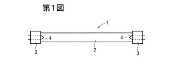
第1図は放電灯の一般的な構成を示す側面図である。
[Discharge lamp structure]
FIG. 1 is a side view showing a general configuration of a discharge lamp.
この放電灯1は、石英ガラス製のガラス管2と、該ガラス管2の両端に設けられた閉止部材3と、該閉止部材3に保持され、ガラス管2内に配置されたフィラメント4と、該ガラス管2内に封入された発光金属及び希ガス(例えばアルゴン、キセノン)を有する。発光金属としては水銀又は水銀化合物、希土類金属元素などが用いられる。
The discharge lamp 1 includes a
閉止部材3は、前記特許4025462のように、カップ状の口金部と、該口金部内に配置されたガラスステムと、該ガラスステムに保持された1対のリードとを備えている。この1対のリード間にフィラメント4が架設されている。
The
この放電灯1を長時間使用すると、発光金属がガラス管内壁面に蒸着などによって付着し、放電灯1が発光しないようになる。 When the discharge lamp 1 is used for a long time, the light emitting metal adheres to the inner wall surface of the glass tube by vapor deposition or the like, and the discharge lamp 1 does not emit light.
このように発光が停止したり、発光量が低下した放電灯を、次のようにして再生する。 The discharge lamp in which the light emission is stopped or the light emission amount is reduced is regenerated as follows.
[放電灯再生方法について]
この再生方法は、(1)ガラス管の切断工程、(2)洗浄工程、(3)切断したガラス管を加熱する加熱工程及び(4)閉止部材取付工程を有する。
[Discharge lamp regeneration method]
This regeneration method includes (1) a glass tube cutting step, (2) a cleaning step, (3) a heating step for heating the cut glass tube, and (4) a closing member attaching step.
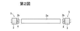
(1)の切断工程では、第2図のように、ガラス管の両端近傍部を切断する。この切断はガラスカッターなどによって行うことができる。フィラメントは両端の閉止部材3から最大30mm程度ガラス管内側に突出しているので、閉止部材3から100mm程度の箇所を切断すればフィラメント4を傷つけることなくガラス管2を切断できる。第2図のように、この切断により、ガラス管2は本体部2aと、2個の端部2bとに分断される。ガラス管端部2bはそれぞれ閉止部材3と一体となっており、この閉止部材3にフィラメント4が保持されている。符号5は、このガラス管端部2bと閉止部材3とフィラメント4とからなる分断物を示している。
In the cutting step (1), the vicinity of both ends of the glass tube is cut as shown in FIG. This cutting can be performed by a glass cutter or the like. Since the filament protrudes from the
その洗浄工程では、純水または揮発性液体でガラス管本体部2aを洗浄し、乾燥させる。純水または揮発性液体によってガラス管を洗浄すれば、ウォーターマークを残すことなく付着物をガラス管内から除去することができる。揮発性液体としてはアルコール類、エーテル等の有機溶剤や二硫化炭素等の無機溶剤などを用いることができる。
In the cleaning step, the glass tube
洗浄液の純度としては、蒸発後の残分が再生放電灯の性能や寿命に影響を与えない程度の純度であればよく、例えば蒸発残留物が10mg/L以下、より好ましくは1mg/L以下であればよい。 The purity of the cleaning liquid may be such that the residue after evaporation does not affect the performance and life of the regenerative discharge lamp. For example, the evaporation residue is 10 mg / L or less, more preferably 1 mg / L or less. I just need it.
(3)の加熱工程では、開放したガラス管本体部2aを300℃以上に加熱する。この加熱温度は、発光金属が酸化・変成・蒸発の何れかの変化を生じさせる温度以上であって、ガラス管2が溶融しない以下の温度であれば特に限定されない。ガラス管が溶融してしまうと当然そのままの形での再生は困難となるから避けなければならない。
In the heating step (3), the opened glass tube
なお、石英ガラスの溶融温度は組成によって必ずしも一定ではない。従って本願発明では加熱温度を300℃以上(より好ましくは500℃以上)かつガラス管2の石英ガラスが溶融する温度未満(好ましくは1500℃以下)とする。この加熱時間は、5秒以上とすれば発光金属の除去効果がみられるが、1分以上、特に10〜60分程度加熱すればより確実である。
Note that the melting temperature of quartz glass is not necessarily constant depending on the composition. Therefore, in this invention, heating temperature shall be 300 degreeC or more (more preferably 500 degreeC or more) and less than the temperature (preferably 1500 degreeC or less) which the quartz glass of the
なお、切断したガラス管端部2bについては、内壁面の付着物をエアブロー又はエアブラストすることにより除去するようにしてもよく、除去処理をしなくてもよい。
In addition, about the cut | disconnected glass
(4)の閉止部材取付工程では、再びガラス管に発光金属および希ガスを封入して分断物5を取り付ける。このとき希ガス雰囲気下で発光金属封入と分断物5の取り付けを行うことにより、ガラス管2内に希ガスを封入できる。この取り付ける両端部としては、(1)の切断工程で切断した分断物5が好適であるが、新品のガラス管端部2bに交換したものであってもよい。この分断物5は、そのガラス管端部2bを溶接によってガラス管本体部2aに取り付けることができる。
In the closing member attaching step (4), the light emitting metal and the rare gas are again sealed in the glass tube, and the
[酸洗浄について]
ガラス管の切断工程(1)とガラス管の洗浄工程(2)との間で、0.1wt%以上(例えば0.1〜5wt%)のフッ化水素酸水溶液、0.1wt%以上(例えば0.1〜5wt%)の硝酸水溶液、フッ化水素酸及び硝酸を合わせて0.1wt%以上(例えば0.1〜5wt%)含む水溶液のいずれかによって洗浄し、次に純水又は揮発性液体を使って内部を洗浄することで、ガラス管内壁面の付着物が十分に除去され、再生後の発光量の回復が進み、場合によっては元の放電光の量以上の光量が得られる。
[Acid cleaning]
Between the glass tube cutting step (1) and the glass tube cleaning step (2), 0.1 wt% or more (for example, 0.1 to 5 wt%) hydrofluoric acid aqueous solution, 0.1 wt% or more (for example, 0.1-5 wt% nitric acid aqueous solution, and a combination of hydrofluoric acid and nitric acid containing 0.1 wt% or more (for example, 0.1-5 wt%) followed by pure water or volatile By cleaning the inside with a liquid, the deposits on the inner wall surface of the glass tube are sufficiently removed, the recovery of the light emission amount after the regeneration proceeds, and in some cases, a light amount greater than the amount of the original discharge light can be obtained.
フッ化水素酸洗浄等の酸洗浄を加熱後に行ってしまうと、フッ化水素酸と石英ガラスに含まれる不純物とが結合したままガラス管内に残留し、ガラス管再生後に絶縁破壊や発光量低下などの影響が出る恐れがあるため、フッ化水素酸洗浄等の酸洗浄は必ず加熱前に行う必要がある。 If acid cleaning such as hydrofluoric acid cleaning is performed after heating, hydrofluoric acid and the impurities contained in the quartz glass remain in the glass tube as they are combined, and dielectric breakdown and reduction in light emission after glass tube regeneration, etc. Therefore, acid cleaning such as hydrofluoric acid cleaning must be performed before heating.
[実施例1]
乾燥後発光が失われた第1図に示す紫外線殺菌用の水銀蒸気放電灯1(ガラス管2の外径10.6mm、内径8mm、長さ1080mm)の両端から100mmの箇所をそれぞれガラスカッターによって切断した。このように両端部を分離した残りの約880mm長のガラス管本体部2aの内外面を純水で2分間洗浄した。この洗浄はガラス管を縦にして上側から純水を流し落とすことにより行った。その後、ガラス管本体部2を乾燥器で乾燥させた。次いでガラス管本体部2aをガスバーナーで300℃に加熱した。この加熱は、ガスバーナーとガラス管本体部2aとを相対的に移動させるようにして行い、ガラス管本体部2aの全領域について10〜300秒にわたって700℃に加熱した。
[Example 1]
The mercury vapor discharge lamp 1 for UV sterilization shown in FIG. 1 where the luminescence is lost after drying (the outer diameter of the
この加熱後、室温まで放冷した。 After this heating, the mixture was allowed to cool to room temperature.
このガラス管2aをアルゴンガス100mg/Lと、キセノンガス25mg/L、および水銀50mg/Lを含む、10トールの減圧空気の下に置き、切断工程で分離した分断物5を、接着剤を用いて仮付けし、放電灯の内部を真空に保ったまま取り出した。次いで、ガラス管本体部2aと、接着剤で仮付けした分断物5のガラス管端部2bとをガスバーナーで1300℃に加熱して溶着させ、再生放電灯とした。
The
これを発光が得られていた当時と同じ器具に再び取り付けた。その結果、紫外線量がおよそ10%低下したものの発光が回復し、600時間以上連続発光した。なお、この放電灯のメーカーによる想定寿命は、最短500時間であった。 This was re-attached to the same instrument that was used to emit light. As a result, although the amount of ultraviolet rays decreased by about 10%, light emission was recovered and continuous light emission continued for 600 hours or more. The expected life of the discharge lamp manufacturer was 500 hours at the shortest.
[実施例2]
実施例1において、切断後加熱前のガラス管本体部2aについて、0.1wt%のフッ化水素酸水溶液で1分間洗浄し、その後純水で2分間内外面を洗浄した。
[Example 2]
In Example 1, the glass tube
その他は実施例1と同様にして再生放電灯を製作した。これを発光が得られていた当時と同じ器具に再び取り付けた。その結果、発光が回復し、600時間以上連続発光した。なお、本実施例では紫外線量の低下もなかった。 Other than that, a regenerative discharge lamp was manufactured in the same manner as in Example 1. This was re-attached to the same instrument that was used to emit light. As a result, light emission was recovered and continuous light emission was continued for 600 hours or more. In this example, there was no decrease in the amount of ultraviolet rays.
[比較例1]
実施例1において、切断工程の後、ガラス管本体部2aの内部を洗浄も加熱もせず、直ちにアルゴンガス100mg/Lと、キセノンガス25mg/L、および水銀50mg/Lを含む、10トールの減圧空気の下に置いて分断物5を溶接したこと以外は同様にして再生放電灯を製作した。これを発光が得られていた当時と同じ器具に再び取り付けた。
[Comparative Example 1]
In Example 1, after the cutting step, the inside of the glass tube
その結果、ガラス内面の一部に偏在して蒸着していた発光金属に放電が集中し、発光の初期値が半分以下に低下した。また、3時間後にガラス管が絶縁破壊を起こして破損した。 As a result, the discharge concentrated on the light emitting metal that was unevenly distributed on a part of the inner surface of the glass, and the initial value of light emission was reduced to less than half. Further, after 3 hours, the glass tube was broken due to dielectric breakdown.
[比較例2]
次に、同じ紫外線灯で同じく発光が失われたものを用意し、上記の加熱工程と洗浄工程との順番のみを変えて、まず加熱を行った後、0.1wt%フッ化水素酸水溶液による洗浄を行い、次に純水で管内を洗ってから、上記と同じ条件下で内部の封入ガスのみを復旧させた。その結果、ガラス管内面に残っていたフッ素と石英ガラス内の不純物である金属イオンとが結合したとみられる物質に放電が集中し、20時間後に放電管が絶縁破壊を起こして破損した。
[Comparative Example 2]
Next, the same ultraviolet lamp with the same emission lost is prepared, and only the heating process and the cleaning process are changed in order, and then heating is performed, and then the 0.1 wt% hydrofluoric acid aqueous solution is used. Washing was performed, and then the inside of the tube was washed with pure water, and then only the enclosed gas was restored under the same conditions as described above. As a result, the discharge was concentrated on the substance that seems to be a combination of fluorine remaining on the inner surface of the glass tube and metal ions as impurities in the quartz glass, and after 20 hours, the discharge tube was broken due to dielectric breakdown.
1 放電灯
2 ガラス管
2a ガラス管本体部
2b ガラス管端部
3 閉止部材
4 フィラメント
5 分断物
DESCRIPTION OF SYMBOLS 1
Claims (2)
該ガラス管の両端部近傍を切断して前記フィラメントを保持した前記閉止部材をガラス管から分離する切断工程と、
前記閉止部材が分離されることにより両端が開放したガラス管に対し純水または揮発性液体でガラス管の内外面を洗浄し、乾燥させる洗浄工程と、
ガラス管内部を300℃以上かつ該石英ガラスが溶融する温度よりも低い温度で5秒間以上加熱する加熱工程と、
前記ガラス管に発光金属および希ガスを封入し、前記フィラメントを保持した前記閉止部材を両端に取り付ける閉止部材取付工程と、
を有する放電灯再生方法。 A glass tube made of quartz glass, a closing member provided at each end of the glass tube, a filament held by the closing member, and a luminescent metal and a noble gas sealed in the glass tube, In a discharge lamp regeneration method for regenerating a discharge lamp in which at least a part of the luminescent metal is attached to the inner wall of the glass tube,
A cutting step of cutting the vicinity of both ends of the glass tube and separating the closing member holding the filament from the glass tube;
A cleaning step of cleaning the inner and outer surfaces of the glass tube with pure water or a volatile liquid with respect to the glass tube whose both ends are opened by separating the closing member, and drying,
A heating step of heating the interior of the glass tube at 300 ° C. or higher and at a temperature lower than the temperature at which the quartz glass melts for 5 seconds or more;
A closing member attaching step for enclosing the light emitting metal and the rare gas in the glass tube and attaching the closing member holding the filament to both ends;
A discharge lamp regeneration method comprising:
Priority Applications (1)
| Application Number | Priority Date | Filing Date | Title |
|---|---|---|---|
| JP2008223633A JP5256944B2 (en) | 2008-09-01 | 2008-09-01 | Discharge lamp regeneration method |
Applications Claiming Priority (1)
| Application Number | Priority Date | Filing Date | Title |
|---|---|---|---|
| JP2008223633A JP5256944B2 (en) | 2008-09-01 | 2008-09-01 | Discharge lamp regeneration method |
Publications (2)
| Publication Number | Publication Date |
|---|---|
| JP2010061854A true JP2010061854A (en) | 2010-03-18 |
| JP5256944B2 JP5256944B2 (en) | 2013-08-07 |
Family
ID=42188453
Family Applications (1)
| Application Number | Title | Priority Date | Filing Date |
|---|---|---|---|
| JP2008223633A Expired - Fee Related JP5256944B2 (en) | 2008-09-01 | 2008-09-01 | Discharge lamp regeneration method |
Country Status (1)
| Country | Link |
|---|---|
| JP (1) | JP5256944B2 (en) |
Cited By (1)
| Publication number | Priority date | Publication date | Assignee | Title |
|---|---|---|---|---|
| JP2011243419A (en) * | 2010-05-18 | 2011-12-01 | Toshiba Corp | Recovery method for recovering bulb from image tube and manufacturing method of image tube |
Citations (5)
| Publication number | Priority date | Publication date | Assignee | Title |
|---|---|---|---|---|
| JPS4932488A (en) * | 1972-07-24 | 1974-03-25 | ||
| JP2001345047A (en) * | 1999-10-15 | 2001-12-14 | Toshiba Lighting & Technology Corp | Manufacturing method of fluorescent lamp, fluorescent lamp and illumination device |
| JP2001345051A (en) * | 2000-03-30 | 2001-12-14 | Toshiba Lighting & Technology Corp | Regeneration method of fluorescent lamp |
| JP2002301462A (en) * | 2001-04-06 | 2002-10-15 | Hisao Takahashi | Intermediate treating method in disposal of mercury lamp |
| JP2008066164A (en) * | 2006-09-08 | 2008-03-21 | Matsushita Electric Ind Co Ltd | Regeneration method of lighting device, liquid crystal display device, and fluorescent lamp, and heating device |
-
2008
- 2008-09-01 JP JP2008223633A patent/JP5256944B2/en not_active Expired - Fee Related
Patent Citations (5)
| Publication number | Priority date | Publication date | Assignee | Title |
|---|---|---|---|---|
| JPS4932488A (en) * | 1972-07-24 | 1974-03-25 | ||
| JP2001345047A (en) * | 1999-10-15 | 2001-12-14 | Toshiba Lighting & Technology Corp | Manufacturing method of fluorescent lamp, fluorescent lamp and illumination device |
| JP2001345051A (en) * | 2000-03-30 | 2001-12-14 | Toshiba Lighting & Technology Corp | Regeneration method of fluorescent lamp |
| JP2002301462A (en) * | 2001-04-06 | 2002-10-15 | Hisao Takahashi | Intermediate treating method in disposal of mercury lamp |
| JP2008066164A (en) * | 2006-09-08 | 2008-03-21 | Matsushita Electric Ind Co Ltd | Regeneration method of lighting device, liquid crystal display device, and fluorescent lamp, and heating device |
Cited By (1)
| Publication number | Priority date | Publication date | Assignee | Title |
|---|---|---|---|---|
| JP2011243419A (en) * | 2010-05-18 | 2011-12-01 | Toshiba Corp | Recovery method for recovering bulb from image tube and manufacturing method of image tube |
Also Published As
| Publication number | Publication date |
|---|---|
| JP5256944B2 (en) | 2013-08-07 |
Similar Documents
| Publication | Publication Date | Title |
|---|---|---|
| JP4569636B2 (en) | Excimer discharge lamp | |
| JP3687582B2 (en) | Discharge lamp | |
| JP2004006357A (en) | Electric lamp, high intensity discharge lamp, and electric lamp operating method | |
| JP5256944B2 (en) | Discharge lamp regeneration method | |
| JP3320376B2 (en) | Discharge lamp and method of manufacturing the same | |
| JP3995053B1 (en) | HID lamp | |
| JP2007188802A (en) | High-pressure discharge lamp | |
| US6316875B1 (en) | Electroded selenium lamp | |
| JP2005510033A (en) | Hollow cathode with integrated getter for discharge lamp and method for its implementation | |
| JP3411810B2 (en) | Ceramic discharge lamp | |
| JPH10312751A (en) | Manufacture of discharge lamp made of ceramic | |
| JP4091473B2 (en) | Lamp manufacturing method | |
| JP3527863B2 (en) | Lamp manufacturing method | |
| JP2008277091A (en) | Discharge lamp manufacturing method | |
| JP4507040B2 (en) | Metal vapor discharge lamp and method for producing metal vapor discharge lamp | |
| JP5578491B2 (en) | Flash lamp | |
| KR20220045890A (en) | Lamp sealing structure, lamp, and method of lamp sealing | |
| JP4792863B2 (en) | High pressure discharge lamp | |
| JPS6124125A (en) | Manufacturing of high pressure discharging lamp | |
| JPH1167151A (en) | Recycled fluorescent lamp | |
| JPS5836810B2 (en) | How to regenerate the arc tube of a high-pressure alkali metal vapor discharge lamp | |
| JPH07169401A (en) | Manufacture of metal halide lamp and its illumination method | |
| JP2010097903A (en) | Electrode for emitting electron and cold-cathode fluorescent lamp | |
| FR2939961A1 (en) | HALOGEN LAMP | |
| JPH10125283A (en) | Low-pressure mercury vapor discharge lamp |
Legal Events
| Date | Code | Title | Description |
|---|---|---|---|
| A621 | Written request for application examination |
Free format text: JAPANESE INTERMEDIATE CODE: A621 Effective date: 20110801 |
|
| A977 | Report on retrieval |
Free format text: JAPANESE INTERMEDIATE CODE: A971007 Effective date: 20121129 |
|
| A131 | Notification of reasons for refusal |
Free format text: JAPANESE INTERMEDIATE CODE: A131 Effective date: 20130108 |
|
| A521 | Request for written amendment filed |
Free format text: JAPANESE INTERMEDIATE CODE: A523 Effective date: 20130307 |
|
| TRDD | Decision of grant or rejection written | ||
| A01 | Written decision to grant a patent or to grant a registration (utility model) |
Free format text: JAPANESE INTERMEDIATE CODE: A01 Effective date: 20130326 |
|
| A61 | First payment of annual fees (during grant procedure) |
Free format text: JAPANESE INTERMEDIATE CODE: A61 Effective date: 20130408 |
|
| FPAY | Renewal fee payment (event date is renewal date of database) |
Free format text: PAYMENT UNTIL: 20160502 Year of fee payment: 3 |
|
| R150 | Certificate of patent or registration of utility model |
Ref document number: 5256944 Country of ref document: JP Free format text: JAPANESE INTERMEDIATE CODE: R150 Free format text: JAPANESE INTERMEDIATE CODE: R150 |
|
| LAPS | Cancellation because of no payment of annual fees |