JP2010061804A - Optical disk and optical disk address reading device and method - Google Patents
Optical disk and optical disk address reading device and method Download PDFInfo
- Publication number
- JP2010061804A JP2010061804A JP2009282778A JP2009282778A JP2010061804A JP 2010061804 A JP2010061804 A JP 2010061804A JP 2009282778 A JP2009282778 A JP 2009282778A JP 2009282778 A JP2009282778 A JP 2009282778A JP 2010061804 A JP2010061804 A JP 2010061804A
- Authority
- JP
- Japan
- Prior art keywords
- groove
- mark
- signal
- negative
- positive
- Prior art date
- Legal status (The legal status is an assumption and is not a legal conclusion. Google has not performed a legal analysis and makes no representation as to the accuracy of the status listed.)
- Granted
Links
Images


Classifications
-
- G—PHYSICS
- G11—INFORMATION STORAGE
- G11B—INFORMATION STORAGE BASED ON RELATIVE MOVEMENT BETWEEN RECORD CARRIER AND TRANSDUCER
- G11B27/00—Editing; Indexing; Addressing; Timing or synchronising; Monitoring; Measuring tape travel
- G11B27/10—Indexing; Addressing; Timing or synchronising; Measuring tape travel
- G11B27/19—Indexing; Addressing; Timing or synchronising; Measuring tape travel by using information detectable on the record carrier
- G11B27/24—Indexing; Addressing; Timing or synchronising; Measuring tape travel by using information detectable on the record carrier by sensing features on the record carrier other than the transducing track ; sensing signals or marks recorded by another method than the main recording
-
- G—PHYSICS
- G11—INFORMATION STORAGE
- G11B—INFORMATION STORAGE BASED ON RELATIVE MOVEMENT BETWEEN RECORD CARRIER AND TRANSDUCER
- G11B20/00—Signal processing not specific to the method of recording or reproducing; Circuits therefor
- G11B20/00086—Circuits for prevention of unauthorised reproduction or copying, e.g. piracy
- G11B20/00572—Circuits for prevention of unauthorised reproduction or copying, e.g. piracy involving measures which change the format of the recording medium
- G11B20/00586—Circuits for prevention of unauthorised reproduction or copying, e.g. piracy involving measures which change the format of the recording medium said format change concerning the physical format of the recording medium
- G11B20/00601—Circuits for prevention of unauthorised reproduction or copying, e.g. piracy involving measures which change the format of the recording medium said format change concerning the physical format of the recording medium wherein properties of tracks are altered, e.g., by changing the wobble pattern or the track pitch, or by adding interruptions or eccentricity
-
- G—PHYSICS
- G11—INFORMATION STORAGE
- G11B—INFORMATION STORAGE BASED ON RELATIVE MOVEMENT BETWEEN RECORD CARRIER AND TRANSDUCER
- G11B20/00—Signal processing not specific to the method of recording or reproducing; Circuits therefor
- G11B20/10—Digital recording or reproducing
- G11B20/10009—Improvement or modification of read or write signals
- G11B20/10222—Improvement or modification of read or write signals clock-related aspects, e.g. phase or frequency adjustment or bit synchronisation
- G11B20/10231—Improvement or modification of read or write signals clock-related aspects, e.g. phase or frequency adjustment or bit synchronisation wherein an asynchronous, free-running clock is used; Interpolation of sampled signals
-
- G—PHYSICS
- G11—INFORMATION STORAGE
- G11B—INFORMATION STORAGE BASED ON RELATIVE MOVEMENT BETWEEN RECORD CARRIER AND TRANSDUCER
- G11B20/00—Signal processing not specific to the method of recording or reproducing; Circuits therefor
- G11B20/10—Digital recording or reproducing
- G11B20/10009—Improvement or modification of read or write signals
- G11B20/10268—Improvement or modification of read or write signals bit detection or demodulation methods
-
- G—PHYSICS
- G11—INFORMATION STORAGE
- G11B—INFORMATION STORAGE BASED ON RELATIVE MOVEMENT BETWEEN RECORD CARRIER AND TRANSDUCER
- G11B20/00—Signal processing not specific to the method of recording or reproducing; Circuits therefor
- G11B20/10—Digital recording or reproducing
- G11B20/12—Formatting, e.g. arrangement of data block or words on the record carriers
- G11B20/1217—Formatting, e.g. arrangement of data block or words on the record carriers on discs
- G11B20/1252—Formatting, e.g. arrangement of data block or words on the record carriers on discs for discontinuous data, e.g. digital information signals, computer programme data
-
- G—PHYSICS
- G11—INFORMATION STORAGE
- G11B—INFORMATION STORAGE BASED ON RELATIVE MOVEMENT BETWEEN RECORD CARRIER AND TRANSDUCER
- G11B20/00—Signal processing not specific to the method of recording or reproducing; Circuits therefor
- G11B20/10—Digital recording or reproducing
- G11B20/14—Digital recording or reproducing using self-clocking codes
- G11B20/1403—Digital recording or reproducing using self-clocking codes characterised by the use of two levels
-
- G—PHYSICS
- G11—INFORMATION STORAGE
- G11B—INFORMATION STORAGE BASED ON RELATIVE MOVEMENT BETWEEN RECORD CARRIER AND TRANSDUCER
- G11B20/00—Signal processing not specific to the method of recording or reproducing; Circuits therefor
- G11B20/10—Digital recording or reproducing
- G11B20/18—Error detection or correction; Testing, e.g. of drop-outs
- G11B20/1833—Error detection or correction; Testing, e.g. of drop-outs by adding special lists or symbols to the coded information
-
- G—PHYSICS
- G11—INFORMATION STORAGE
- G11B—INFORMATION STORAGE BASED ON RELATIVE MOVEMENT BETWEEN RECORD CARRIER AND TRANSDUCER
- G11B27/00—Editing; Indexing; Addressing; Timing or synchronising; Monitoring; Measuring tape travel
- G11B27/10—Indexing; Addressing; Timing or synchronising; Measuring tape travel
- G11B27/102—Programmed access in sequence to addressed parts of tracks of operating record carriers
- G11B27/105—Programmed access in sequence to addressed parts of tracks of operating record carriers of operating discs
-
- G—PHYSICS
- G11—INFORMATION STORAGE
- G11B—INFORMATION STORAGE BASED ON RELATIVE MOVEMENT BETWEEN RECORD CARRIER AND TRANSDUCER
- G11B27/00—Editing; Indexing; Addressing; Timing or synchronising; Monitoring; Measuring tape travel
- G11B27/10—Indexing; Addressing; Timing or synchronising; Measuring tape travel
- G11B27/19—Indexing; Addressing; Timing or synchronising; Measuring tape travel by using information detectable on the record carrier
- G11B27/28—Indexing; Addressing; Timing or synchronising; Measuring tape travel by using information detectable on the record carrier by using information signals recorded by the same method as the main recording
- G11B27/30—Indexing; Addressing; Timing or synchronising; Measuring tape travel by using information detectable on the record carrier by using information signals recorded by the same method as the main recording on the same track as the main recording
- G11B27/3027—Indexing; Addressing; Timing or synchronising; Measuring tape travel by using information detectable on the record carrier by using information signals recorded by the same method as the main recording on the same track as the main recording used signal is digitally coded
-
- G—PHYSICS
- G11—INFORMATION STORAGE
- G11B—INFORMATION STORAGE BASED ON RELATIVE MOVEMENT BETWEEN RECORD CARRIER AND TRANSDUCER
- G11B7/00—Recording or reproducing by optical means, e.g. recording using a thermal beam of optical radiation by modifying optical properties or the physical structure, reproducing using an optical beam at lower power by sensing optical properties; Record carriers therefor
- G11B7/002—Recording, reproducing or erasing systems characterised by the shape or form of the carrier
- G11B7/0037—Recording, reproducing or erasing systems characterised by the shape or form of the carrier with discs
-
- G—PHYSICS
- G11—INFORMATION STORAGE
- G11B—INFORMATION STORAGE BASED ON RELATIVE MOVEMENT BETWEEN RECORD CARRIER AND TRANSDUCER
- G11B7/00—Recording or reproducing by optical means, e.g. recording using a thermal beam of optical radiation by modifying optical properties or the physical structure, reproducing using an optical beam at lower power by sensing optical properties; Record carriers therefor
- G11B7/007—Arrangement of the information on the record carrier, e.g. form of tracks, actual track shape, e.g. wobbled, or cross-section, e.g. v-shaped; Sequential information structures, e.g. sectoring or header formats within a track
- G11B7/00745—Sectoring or header formats within a track
-
- G—PHYSICS
- G11—INFORMATION STORAGE
- G11B—INFORMATION STORAGE BASED ON RELATIVE MOVEMENT BETWEEN RECORD CARRIER AND TRANSDUCER
- G11B7/00—Recording or reproducing by optical means, e.g. recording using a thermal beam of optical radiation by modifying optical properties or the physical structure, reproducing using an optical beam at lower power by sensing optical properties; Record carriers therefor
- G11B7/08—Disposition or mounting of heads or light sources relatively to record carriers
- G11B7/09—Disposition or mounting of heads or light sources relatively to record carriers with provision for moving the light beam or focus plane for the purpose of maintaining alignment of the light beam relative to the record carrier during transducing operation, e.g. to compensate for surface irregularities of the latter or for track following
- G11B7/0943—Methods and circuits for performing mathematical operations on individual detector segment outputs
-
- G—PHYSICS
- G11—INFORMATION STORAGE
- G11B—INFORMATION STORAGE BASED ON RELATIVE MOVEMENT BETWEEN RECORD CARRIER AND TRANSDUCER
- G11B7/00—Recording or reproducing by optical means, e.g. recording using a thermal beam of optical radiation by modifying optical properties or the physical structure, reproducing using an optical beam at lower power by sensing optical properties; Record carriers therefor
- G11B7/12—Heads, e.g. forming of the optical beam spot or modulation of the optical beam
- G11B7/125—Optical beam sources therefor, e.g. laser control circuitry specially adapted for optical storage devices; Modulators, e.g. means for controlling the size or intensity of optical spots or optical traces
- G11B7/127—Lasers; Multiple laser arrays
-
- G—PHYSICS
- G11—INFORMATION STORAGE
- G11B—INFORMATION STORAGE BASED ON RELATIVE MOVEMENT BETWEEN RECORD CARRIER AND TRANSDUCER
- G11B20/00—Signal processing not specific to the method of recording or reproducing; Circuits therefor
- G11B20/10—Digital recording or reproducing
- G11B20/10009—Improvement or modification of read or write signals
-
- G—PHYSICS
- G11—INFORMATION STORAGE
- G11B—INFORMATION STORAGE BASED ON RELATIVE MOVEMENT BETWEEN RECORD CARRIER AND TRANSDUCER
- G11B7/00—Recording or reproducing by optical means, e.g. recording using a thermal beam of optical radiation by modifying optical properties or the physical structure, reproducing using an optical beam at lower power by sensing optical properties; Record carriers therefor
- G11B7/007—Arrangement of the information on the record carrier, e.g. form of tracks, actual track shape, e.g. wobbled, or cross-section, e.g. v-shaped; Sequential information structures, e.g. sectoring or header formats within a track
- G11B2007/00754—Track shape, e.g. address or synchronisation information in wobbled track or sidewall
-
- G—PHYSICS
- G11—INFORMATION STORAGE
- G11B—INFORMATION STORAGE BASED ON RELATIVE MOVEMENT BETWEEN RECORD CARRIER AND TRANSDUCER
- G11B20/00—Signal processing not specific to the method of recording or reproducing; Circuits therefor
- G11B20/10—Digital recording or reproducing
- G11B20/12—Formatting, e.g. arrangement of data block or words on the record carriers
- G11B20/1217—Formatting, e.g. arrangement of data block or words on the record carriers on discs
- G11B2020/1218—Formatting, e.g. arrangement of data block or words on the record carriers on discs wherein the formatting concerns a specific area of the disc
- G11B2020/1232—Formatting, e.g. arrangement of data block or words on the record carriers on discs wherein the formatting concerns a specific area of the disc sector, i.e. the minimal addressable physical data unit
-
- G—PHYSICS
- G11—INFORMATION STORAGE
- G11B—INFORMATION STORAGE BASED ON RELATIVE MOVEMENT BETWEEN RECORD CARRIER AND TRANSDUCER
- G11B20/00—Signal processing not specific to the method of recording or reproducing; Circuits therefor
- G11B20/10—Digital recording or reproducing
- G11B20/12—Formatting, e.g. arrangement of data block or words on the record carriers
- G11B20/1217—Formatting, e.g. arrangement of data block or words on the record carriers on discs
- G11B2020/1218—Formatting, e.g. arrangement of data block or words on the record carriers on discs wherein the formatting concerns a specific area of the disc
- G11B2020/1238—Formatting, e.g. arrangement of data block or words on the record carriers on discs wherein the formatting concerns a specific area of the disc track, i.e. the entire a spirally or concentrically arranged path on which the recording marks are located
- G11B2020/1239—Formatting, e.g. arrangement of data block or words on the record carriers on discs wherein the formatting concerns a specific area of the disc track, i.e. the entire a spirally or concentrically arranged path on which the recording marks are located the track being a pregroove, e.g. the wobbled track of a recordable optical disc
-
- G—PHYSICS
- G11—INFORMATION STORAGE
- G11B—INFORMATION STORAGE BASED ON RELATIVE MOVEMENT BETWEEN RECORD CARRIER AND TRANSDUCER
- G11B20/00—Signal processing not specific to the method of recording or reproducing; Circuits therefor
- G11B20/10—Digital recording or reproducing
- G11B20/12—Formatting, e.g. arrangement of data block or words on the record carriers
- G11B2020/1264—Formatting, e.g. arrangement of data block or words on the record carriers wherein the formatting concerns a specific kind of data
- G11B2020/1265—Control data, system data or management information, i.e. data used to access or process user data
- G11B2020/1267—Address data
- G11B2020/1268—Address in pregroove [ADIP] information
-
- G—PHYSICS
- G11—INFORMATION STORAGE
- G11B—INFORMATION STORAGE BASED ON RELATIVE MOVEMENT BETWEEN RECORD CARRIER AND TRANSDUCER
- G11B20/00—Signal processing not specific to the method of recording or reproducing; Circuits therefor
- G11B20/10—Digital recording or reproducing
- G11B20/12—Formatting, e.g. arrangement of data block or words on the record carriers
- G11B2020/1264—Formatting, e.g. arrangement of data block or words on the record carriers wherein the formatting concerns a specific kind of data
- G11B2020/1265—Control data, system data or management information, i.e. data used to access or process user data
- G11B2020/1267—Address data
- G11B2020/1269—Absolute time in pregroove [ATIP] information
-
- G—PHYSICS
- G11—INFORMATION STORAGE
- G11B—INFORMATION STORAGE BASED ON RELATIVE MOVEMENT BETWEEN RECORD CARRIER AND TRANSDUCER
- G11B20/00—Signal processing not specific to the method of recording or reproducing; Circuits therefor
- G11B20/10—Digital recording or reproducing
- G11B20/12—Formatting, e.g. arrangement of data block or words on the record carriers
- G11B2020/1264—Formatting, e.g. arrangement of data block or words on the record carriers wherein the formatting concerns a specific kind of data
- G11B2020/1265—Control data, system data or management information, i.e. data used to access or process user data
- G11B2020/1287—Synchronisation pattern, e.g. VCO fields
-
- G—PHYSICS
- G11—INFORMATION STORAGE
- G11B—INFORMATION STORAGE BASED ON RELATIVE MOVEMENT BETWEEN RECORD CARRIER AND TRANSDUCER
- G11B20/00—Signal processing not specific to the method of recording or reproducing; Circuits therefor
- G11B20/10—Digital recording or reproducing
- G11B20/12—Formatting, e.g. arrangement of data block or words on the record carriers
- G11B2020/1291—Formatting, e.g. arrangement of data block or words on the record carriers wherein the formatting serves a specific purpose
- G11B2020/1292—Enhancement of the total storage capacity
-
- G—PHYSICS
- G11—INFORMATION STORAGE
- G11B—INFORMATION STORAGE BASED ON RELATIVE MOVEMENT BETWEEN RECORD CARRIER AND TRANSDUCER
- G11B20/00—Signal processing not specific to the method of recording or reproducing; Circuits therefor
- G11B20/10—Digital recording or reproducing
- G11B20/12—Formatting, e.g. arrangement of data block or words on the record carriers
- G11B2020/1291—Formatting, e.g. arrangement of data block or words on the record carriers wherein the formatting serves a specific purpose
- G11B2020/1298—Enhancement of the signal quality
-
- G—PHYSICS
- G11—INFORMATION STORAGE
- G11B—INFORMATION STORAGE BASED ON RELATIVE MOVEMENT BETWEEN RECORD CARRIER AND TRANSDUCER
- G11B2220/00—Record carriers by type
- G11B2220/20—Disc-shaped record carriers
-
- G—PHYSICS
- G11—INFORMATION STORAGE
- G11B—INFORMATION STORAGE BASED ON RELATIVE MOVEMENT BETWEEN RECORD CARRIER AND TRANSDUCER
- G11B2220/00—Record carriers by type
- G11B2220/20—Disc-shaped record carriers
- G11B2220/21—Disc-shaped record carriers characterised in that the disc is of read-only, rewritable, or recordable type
- G11B2220/215—Recordable discs
- G11B2220/216—Rewritable discs
-
- G—PHYSICS
- G11—INFORMATION STORAGE
- G11B—INFORMATION STORAGE BASED ON RELATIVE MOVEMENT BETWEEN RECORD CARRIER AND TRANSDUCER
- G11B2220/00—Record carriers by type
- G11B2220/20—Disc-shaped record carriers
- G11B2220/25—Disc-shaped record carriers characterised in that the disc is based on a specific recording technology
- G11B2220/2525—Magneto-optical [MO] discs
- G11B2220/2529—Mini-discs
-
- G—PHYSICS
- G11—INFORMATION STORAGE
- G11B—INFORMATION STORAGE BASED ON RELATIVE MOVEMENT BETWEEN RECORD CARRIER AND TRANSDUCER
- G11B2220/00—Record carriers by type
- G11B2220/20—Disc-shaped record carriers
- G11B2220/25—Disc-shaped record carriers characterised in that the disc is based on a specific recording technology
- G11B2220/2537—Optical discs
- G11B2220/2545—CDs
-
- G—PHYSICS
- G11—INFORMATION STORAGE
- G11B—INFORMATION STORAGE BASED ON RELATIVE MOVEMENT BETWEEN RECORD CARRIER AND TRANSDUCER
- G11B2220/00—Record carriers by type
- G11B2220/20—Disc-shaped record carriers
- G11B2220/25—Disc-shaped record carriers characterised in that the disc is based on a specific recording technology
- G11B2220/2537—Optical discs
- G11B2220/2562—DVDs [digital versatile discs]; Digital video discs; MMCDs; HDCDs
- G11B2220/2575—DVD-RAMs
-
- G—PHYSICS
- G11—INFORMATION STORAGE
- G11B—INFORMATION STORAGE BASED ON RELATIVE MOVEMENT BETWEEN RECORD CARRIER AND TRANSDUCER
- G11B7/00—Recording or reproducing by optical means, e.g. recording using a thermal beam of optical radiation by modifying optical properties or the physical structure, reproducing using an optical beam at lower power by sensing optical properties; Record carriers therefor
Abstract
Description
本発明は、光学的に書き換え可能な光ディスクならびに光ディスクに予め書き込まれたアドレスの読取装置および方法に関する。 The present invention relates to an optically rewritable optical disc and an apparatus and method for reading an address written in advance on the optical disc.
近年、ユーザによる記録が可能な光ディスクとして、DVD−RAM、CD−RW、MDなどがある。これら記録可能な光ディスクは、らせん状または同心円状の複数のトラックに沿ってグルーブを形成し、グルーブの表面を相変化材料又は光磁気材料で形成することにより作られる。また、光ディスク上の位置を特定するため、トラックには予め書換不可能なマークによりアドレスが記録されている。かかるアドレスの一例が特開平8−315426号明細書に開示されている。
特開平8−315426号明細書によれば、グルーブに不連続部を設け、この不連続部をアドレス信号に対応したパターンに形成するとある。ここで言うアドレス信号に対応したパターンとは、不連続部が現れる毎に反転する2値化信号を言い、ATIP(Absolute Time In Pregroove)信号を生成するためのオン、オフ信号である。従って、不連続部は、単に有りか無しかを表す信号として用いられている。
In recent years, there are DVD-RAM, CD-RW, MD, and the like as optical disks that can be recorded by a user. These recordable optical disks are manufactured by forming grooves along a plurality of spiral or concentric tracks and forming the surface of the grooves with a phase change material or a magneto-optical material. In addition, in order to specify the position on the optical disc, an address is recorded in advance on the track with a non-rewritable mark. An example of such an address is disclosed in JP-A-8-315426.
According to Japanese Patent Laid-Open No. 8-315426, a discontinuous portion is provided in a groove, and the discontinuous portion is formed in a pattern corresponding to an address signal. The pattern corresponding to the address signal here refers to a binary signal that is inverted every time a discontinuous portion appears, and is an on / off signal for generating an ATIP (Absolute Time In Pregroove) signal. Therefore, the discontinuous portion is used as a signal simply indicating whether or not there is a discontinuity.
ところが、より記録密度の高い光ディスクを作るためには、より多くのアドレス情報が必要とされる一方、より効率よくアドレス情報を付与する必要がある。ところが、上記従来例にあっては、不連続部は反転するためのトリガ信号でしかなく、一つの意味の情報(トリガ情報)しか持つことが出来なかった。従って多くのマークが必要である。
また、上記従来例にあっては、ATIP信号を利用しているので、トラックのおよその位置は特定できるが、記録開始点が精度よく検出できない。従って、記録をした後、新たに追加して記録をする場合や、記録済みデータ中の一部を書換する場合、前の必要なデータの上に新たなデータを上書きしてしまうこともある。また、トラックピッチを狭くすると、クロストークが発生しやすくなる。
However, in order to make an optical disc with a higher recording density, more address information is required, but it is necessary to assign address information more efficiently. However, in the above conventional example, the discontinuous portion is only a trigger signal for inversion, and can only have information of one meaning (trigger information). Therefore, many marks are necessary.
In the above conventional example, since the ATIP signal is used, the approximate position of the track can be specified, but the recording start point cannot be detected with high accuracy. Therefore, after recording, when newly recording or rewriting a part of recorded data, new data may be overwritten on the previous necessary data. Further, when the track pitch is narrowed, crosstalk is likely to occur.
本発明は、グルーブに不連続部または変形部を形成し、かかる不連続部または変形部に2つまたはそれ以上の意味を持たせ、より効率よくアドレス情報を付与することが出来る光ディスクを提供する。
また、記録開始点の位置決めの精度を高くすることが可能な光ディスクを提供する。
さらに、トラックピッチを狭くすることが出来る光ディスクを提供する。
また、完全なCLV(Constant Linear Velocity)で記録再生が可能な光ディスクを提供する。
また、本発明は、グルーブの不連続部または変形部に2つまたはそれ以上の意味を持たせてアドレス情報が付与された光ディスクから、かかるアドレス情報を簡単な構成で正確に読み取る装置及び方法を提供する。
The present invention provides an optical disc in which a discontinuous portion or a deformed portion is formed in a groove, two or more meanings are given to the discontinuous portion or the deformed portion, and address information can be given more efficiently. .
Also provided is an optical disc capable of increasing the accuracy of positioning of the recording start point.
Furthermore, an optical disc capable of narrowing the track pitch is provided.
Further, an optical disc capable of recording / reproducing with complete CLV (Constant Linear Velocity) is provided.
The present invention also provides an apparatus and method for accurately reading address information with a simple configuration from an optical disk to which address information is given by giving two or more meanings to a discontinuous portion or a deformed portion of the groove. provide.
請求項1の発明は、らせん状又は同心円状に伸びるトラックを有する書換可能な光ディスクにおいて、
トラックに沿って正弦波状にウォブルさせて形成したグルーブと、
トラックに沿って設けたセクタブロックと、
各セクタブロックを複数に分割して設けたセクタと、
各セクタブロックの先頭のセクタに形成した同期マークと、
各セクタブロックの先頭以外のセクタのそれぞれに形成した正マークまたは負マークとからなる光ディスクであって、
該正マークは、トラック方向に第1幅W1でグルーブが不連続となる第1グルーブ不連続部で形成し、
該負マークは、トラック方向に第2幅W0でグルーブが不連続となる第2グルーブ不連続部で形成し、
該同期マークは、トラック方向に第3幅Wsでグルーブが不連続となる第3グルーブ不連続部で形成したことを特徴とする光ディスクである。
The invention of
A groove formed by wobbled in a sinusoidal shape along the track;
A sector block provided along the track;
Sectors provided by dividing each sector block into a plurality of sectors;
A synchronization mark formed in the first sector of each sector block;
An optical disc composed of a positive mark or a negative mark formed in each sector other than the head of each sector block,
The positive mark is formed by a first groove discontinuous portion having a first width W1 and a discontinuous groove in the track direction,
The negative mark is formed by a second groove discontinuous portion having a second width W0 and a groove discontinuous in the track direction,
The synchronization mark is an optical disc characterized in that it is formed by a third groove discontinuous portion having a third width Ws and a discontinuous groove in the track direction.
請求項2の発明は、上記第1、第2、第3グルーブ不連続部は表面がミラーとなっていることを特徴とする請求項1記載の光ディスクである。 According to a second aspect of the present invention, there is provided the optical disk according to the first aspect, wherein the first, second and third groove discontinuous portions have a mirror surface.
請求項3の発明は、上記第1、第2、第3グルーブ不連続部は、いずれもウォブルするグルーブの振幅最大部に形成したことを特徴とする請求項1記載の光ディスクである。 According to a third aspect of the present invention, in the optical disk according to the first aspect, the first, second and third groove discontinuous portions are formed at the maximum amplitude portion of the wobbled groove.
請求項4の発明は、上記第1、第2、第3グルーブ不連続部は、いずれもウォブルするグルーブの振幅最小部に形成したことを特徴とする請求項1記載の光ディスクである。 According to a fourth aspect of the present invention, there is provided the optical disk according to the first aspect, wherein the first, second and third groove discontinuous portions are all formed in a minimum amplitude portion of the wobbled groove.
請求項5の発明は、上記第1、第2、第3幅W1、W0、Wsは、いずれもグルーブに記録される記録データに含まれる最長マーク長より長く、ウォブル周期の1/2以下であることを特徴とする請求項1記載の光ディスクである。
In the invention of
請求項6の発明は、上記第1、第2、第3幅W1、W0、Wsは、いずれもグルーブに記録される記録データに含まれる最長マーク長より長く、ウォブル周期の1/4以下であることを特徴とする請求項1記載の光ディスクである。
In the invention of
請求項7の発明は、上記第1、第2、第3幅W1、W0、Wsの比率は、いずれかひとつを1とすれば、残り2つを2:4の割合にしたことを特徴とする請求項1記載の光ディスクである。
The invention of claim 7 is characterized in that the ratio of the first, second, and third widths W1, W0, and Ws is set to a ratio of 2: 4 when any one is set to 1. The optical disk according to
請求項8の発明は、上記第1、第2、第3幅W1、W0、Wsの比率は、2:1:4であることを特徴とする請求項1記載の光ディスクである。
The invention according to claim 8 is the optical disk according to
請求項9の発明は、上記第1、第2、第3幅W1、W0、Wsは、それぞれ2バイト、1バイト、4バイトであることを特徴とする請求項1記載の光ディスクである。
The invention according to claim 9 is the optical disc according to
請求項10の発明は、らせん状又は同心円状に伸びるトラックを有する書換可能な光ディスクにおいて、
トラックに沿って正弦波状にウォブルさせて形成したグルーブと、
トラックに沿って設けたセクタブロックと、
各セクタブロックを複数に分割して設けたセクタと、
各セクタブロックの先頭のセクタに形成した同期マークと、
各セクタブロックの先頭以外のセクタのそれぞれに形成した正マークまたは負マークとからなる光ディスクであって、
該正マーク、該負マーク、該同期マークのそれぞれは、グルーブが局部的にトラックの垂直方向であって第1方向にズレるグルーブ上ズレ部、グルーブが局部的にトラックの垂直方向であって第2方向にズレるグルーブ下ズレ部、またはグルーブ下ズレ部とグルーブ上ズレ部の組合せ部のいずれかで形成したことを特徴とする光ディスクである。
The invention of
A groove formed by wobbled in a sinusoidal shape along the track;
A sector block provided along the track;
Sectors provided by dividing each sector block into a plurality of sectors;
A synchronization mark formed in the first sector of each sector block;
An optical disc composed of a positive mark or a negative mark formed in each sector other than the head of each sector block,
Each of the positive mark, the negative mark, and the synchronization mark includes a groove upper shift portion in which the groove is locally perpendicular to the track and the first direction, and the groove is locally in the track vertical direction. An optical disc characterized by being formed by either a groove lower shift portion that is shifted in two directions or a combination portion of a groove lower shift portion and a groove upper shift portion.
請求項11の発明は、該正マークはグルーブ上ズレ部で形成し、該負マークはグルーブ下ズレ部で形成し、該同期マークは、グルーブ下ズレ部とグルーブ上ズレ部の組合せ部で形成したことを特徴とする請求項10記載の光ディスクである。
In the invention of claim 11, the positive mark is formed by a groove upper shift portion, the negative mark is formed by a groove lower shift portion, and the synchronization mark is formed by a combination portion of the groove lower shift portion and the groove upper shift portion. The optical disk according to
請求項12の発明は、上記グルーブ下ズレ部、グルーブ上ズレ部は、それぞれウォブルするグルーブの振幅最大部に設け、トラックの中心方向にズレていることを特徴とする請求項10記載の光ディスクである。 According to a twelfth aspect of the present invention, in the optical disk according to the tenth aspect, the groove lower shift portion and the groove upper shift portion are provided in the maximum amplitude portion of the wobbled groove and are shifted in the center direction of the track. is there.
請求項13の発明は、上記同期マークのグルーブ下ズレ部とグルーブ上ズレ部は、互いにウォブル周期のn+(1/2)倍(nは正の整数)で隣接していることを特徴とする請求項10記載の光ディスクである。
The invention according to claim 13 is characterized in that the groove lower shift portion and the groove upper shift portion of the synchronization mark are adjacent to each other by n + (1/2) times the wobble period (n is a positive integer). An optical disc according to
請求項14の発明は、上記nは0であることを特徴とする請求項13記載の光ディスクである。
The invention of
請求項15の発明は、らせん状又は同心円状に伸びるトラックを有する書換可能な光ディスクにおいて、
トラックに沿って正弦波状にウォブルさせて形成したグルーブと、
トラックに沿って設けたセクタブロックと、
各セクタブロックを複数に分割して設けたセクタと、
各セクタブロックの先頭のセクタに形成した同期マークと、
各セクタブロックの先頭以外のセクタのそれぞれに形成した正マークまたは負マークとからなる光ディスクであって、
該正マーク、該負マーク、該同期マークのそれぞれは、ウォブルするグルーブの谷からウォブル周期の大略1/4の部分までの位相を上下に反転させたグルーブ上り位相反転部、ウォブルするグルーブの山からウォブル周期の大略1/4の部分までの位相を上下に反転させたグルーブ下り位相反転部、グルーブ下り位相反転部とグルーブ上り位相反転部の組合せ部のいずれかで形成したことを特徴とする光ディスクである。
The invention of claim 15 is a rewritable optical disc having tracks extending spirally or concentrically.
A groove formed by wobbled in a sinusoidal shape along the track;
A sector block provided along the track;
Sectors provided by dividing each sector block into a plurality of sectors;
A synchronization mark formed in the first sector of each sector block;
An optical disc composed of a positive mark or a negative mark formed in each sector other than the head of each sector block,
Each of the positive mark, the negative mark, and the synchronization mark is a groove up-phase inverting unit that vertically inverts the phase from the valley of the wobbled groove to approximately a quarter of the wobble period, and a peak of the wobbled groove. To a substantially 1/4 portion of the wobble period, and is formed by any one of a groove down phase inversion unit and a combination of a groove down phase inversion unit and a groove up phase inversion unit. It is an optical disk.
請求項16の発明は、該正マークはグルーブ上り位相反転部で形成し、該負マークはグルーブ下り位相反転部で形成し、該同期マークはグルーブ下り位相反転部とグルーブ上り位相反転部の組合せ部で形成したことを特徴とする請求項15記載の光ディスクである。 According to a sixteenth aspect of the present invention, the positive mark is formed by a groove upstream phase inverter, the negative mark is formed by a groove downstream phase inverter, and the synchronization mark is a combination of a groove downstream phase inverter and a groove upstream phase inverter. The optical disk according to claim 15, wherein the optical disk is formed of a portion.
請求項17の発明は、上記グルーブ下り位相反転部と、グルーブ上り位相反転部のそれぞれの両端は、グルーブが不連続になっていることを特徴とする請求項15記載の光ディスクである。 The invention according to claim 17 is the optical disk according to claim 15, wherein the groove is discontinuous at both ends of the groove down phase inversion unit and the groove up phase inversion unit.
請求項18の発明は、上記グルーブ下り位相反転部と、グルーブ上り位相反転部のそれぞれの両端は、急峻に変位するグルーブであることを特徴とする請求項15記載の光ディスクである。 According to an eighteenth aspect of the present invention, there is provided the optical disk according to the fifteenth aspect, wherein both ends of the groove downstream phase inverting unit and the groove upstream phase inverting unit are abruptly displaced grooves.
請求項19の発明は、らせん状又は同心円状に伸びるトラックを有する書換可能な光ディスクにおいて、
トラックに沿って正弦波状にウォブルさせて形成したグルーブと、
トラックに沿って設け、複数のセクタに分割されたセクタブロックとを有する光ディスクであって、
各セクタブロックの所定の複数のセクタに形成した正マークと、
各セクタブロックの別の所定の複数のセクタに形成した負マークとを有し、
該正マーク、該負マークは、ウォブルする正弦波状のグルーブの一部を変形させ、下から上に急激に変化する第1部分と、上から下に急激に変化する第2部分とを用いて表し、該第1部分と第2部分を用いてセクタブロックのアドレス情報を表すことを特徴とする光ディスクである。
The invention of claim 19 is a rewritable optical disc having tracks extending spirally or concentrically,
A groove formed by wobbled in a sinusoidal shape along the track;
An optical disc having a sector block provided along a track and divided into a plurality of sectors,
A positive mark formed in a predetermined plurality of sectors of each sector block;
Negative marks formed in different predetermined sectors of each sector block,
The positive mark and the negative mark are formed by deforming a part of a wobbled sinusoidal groove and using a first part that changes suddenly from bottom to top and a second part that changes suddenly from top to bottom. An optical disc characterized in that the first part and the second part are used to represent sector block address information.
請求項20の発明は、該正マークは上記第1部で形成し、該負マークは上記第2部で形成したことを特徴とする請求項19記載の光ディスクである。 The twentieth aspect of the invention is an optical disc according to the twentieth aspect, wherein the positive mark is formed by the first part and the negative mark is formed by the second part.
請求項21の発明は、該正マーク、該負マークのそれぞれは、上記第1部を複数サイクル繰り返したもの、上記第2部を複数サイクル繰り返したもののいずれかで形成したことを特徴とする請求項19記載の光ディスクである。
The invention of
請求項22の発明は、該正マークは上記第1部を複数サイクル繰り返したもので形成し、該負マークは上記第2部を複数サイクル繰り返したもので形成したことを特徴とする請求項21記載の光ディスクである。 The invention according to claim 22 is characterized in that the positive mark is formed by repeating the first part for a plurality of cycles, and the negative mark is formed by repeating the second part for a plurality of cycles. The optical disc described.
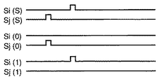
請求項23の発明は、請求項1に記載の光ディスクに含まれる同期マーク、正マーク、負マークを検出し、ひとつのセクタブロックに分散して含まれる正マーク及び負マークから得られる「1」、「0」のデータを集め、該セクタブロックのアドレスを読み取るアドレス読取装置であって、
光ディスクのトラックにレーザ光を照射し、トラック方向に沿って2分割された2つの受光素子で反射光を受光する光ヘッド(2)と、
2つの受光素子からの信号の差を取り、差信号を生成する減算器(4)と、
ウォブルするトラックのウォブル周波数成分を除去し、グルーブ不連続部パルスを生成するフィルタ(6)と、
グルーブ不連続部パルスの幅を検出し、幅に応じて同期マーク、正マーク、負マークを判別し、同期マーク信号、正マーク信号、負マーク信号を生成する判別器(12)と、
ひとつの同期マーク信号から、次の同期マーク信号までに含まれる正マーク信号、負マーク信号に対応して「1」、「0」を生成する復調器(14)とから成ることを特徴とするアドレス読取装置である。
According to a twenty-third aspect of the present invention, the synchronization mark, the positive mark, and the negative mark included in the optical disk according to the first aspect are detected, and “1” obtained from the positive mark and the negative mark dispersedly included in one sector block. , An address reading device that collects data of “0” and reads the address of the sector block,
An optical head (2) that irradiates a track of an optical disc with a laser beam and receives reflected light by two light receiving elements divided into two along the track direction;
A subtractor (4) for taking a difference between signals from the two light receiving elements and generating a difference signal;
A filter (6) for removing a wobble frequency component of a wobbled track and generating a groove discontinuity portion pulse;
A discriminator (12) for detecting a width of the groove discontinuity portion pulse, discriminating a synchronization mark, a positive mark, and a negative mark according to the width, and generating a synchronization mark signal, a positive mark signal, and a negative mark signal;
And a demodulator (14) for generating "1" and "0" corresponding to the positive mark signal and the negative mark signal included from one synchronization mark signal to the next synchronization mark signal. An address reader.
請求項24の発明は、請求項1に記載の光ディスクに含まれる同期マーク、正マーク、負マークを検出し、ひとつのセクタブロックに分散して含まれる正マーク及び負マークから得られる「1」、「0」のデータを集め、該セクタブロックのアドレスを読み取るアドレス読取方法であって、
光ディスクのトラックにレーザ光を照射し、トラック方向に沿って2分割された2つの受光素子で反射光を受光し、
2つの受光素子からの信号の差を取り、差信号を生成し、
ウォブルするトラックのウォブル周波数成分を除去し、グルーブ不連続部パルスを生成し、
グルーブ不連続部パルスの幅を検出し、幅に応じて同期マーク、正マーク、負マークを判別し、同期マーク信号、正マーク信号、負マーク信号を生成し、
ひとつの同期マーク信号から、次の同期マーク信号までに含まれる正マーク信号、負マーク信号に対応して「1」、「0」を生成することを特徴とするアドレス読取方法である。
According to a twenty-fourth aspect of the present invention, the synchronization mark, the positive mark, and the negative mark included in the optical disk according to the first aspect are detected, and “1” obtained from the positive mark and the negative mark dispersedly included in one sector block. , An address reading method for collecting data of “0” and reading the address of the sector block,
Laser light is irradiated onto the track of the optical disc, and the reflected light is received by the two light receiving elements divided into two along the track direction.
The difference between the signals from the two light receiving elements is taken and a difference signal is generated,
Remove wobble frequency component of wobbled track, generate groove discontinuity pulse,
Detects the width of the groove discontinuity pulse, determines the sync mark, positive mark, and negative mark according to the width, generates the sync mark signal, positive mark signal, and negative mark signal,
The address reading method is characterized in that “1” and “0” are generated from one synchronization mark signal corresponding to a positive mark signal and a negative mark signal included in the next synchronization mark signal.
請求項25の発明は、請求項10に記載の光ディスクに含まれる同期マーク、正マーク、負マークを検出し、ひとつのセクタブロックに分散して含まれる正マーク及び負マークから得られる「1」、「0」のデータを集め、該セクタブロックのアドレスを読み取るアドレス読取装置であって、
光ディスクのトラックにレーザ光を照射し、トラック方向に沿って2分割された2つの受光素子で反射光を受光する光ヘッド(2)と、
2つの受光素子からの信号の差を取り、差信号を生成する減算器(4)と、
ウォブルするトラックのウォブル周波数成分を除去し、負方向のグルーブ下ズレ部パルスと正方向のグルーブ上ズレ部パルスを生成するフィルタ(6)と、
正マーク、負マーク、同期マークのそれぞれを、グルーブ上ズレ部パルス、グルーブ下ズレ部パルス、グルーブ下ズレ部パルスとグルーブ上ズレ部パルスの対のいずれかで判別し、正マーク信号、負マーク信号、同期マーク信号を生成する判別器(52,54,12)と、
ひとつの同期マーク信号から、次の同期マーク信号までに含まれる正マーク信号、負マーク信号に対応して「1」、「0」を生成する復調器(14)とから成ることを特徴とするアドレス読取装置である。
The invention of claim 25 detects “1” obtained from the positive mark and the negative mark that are dispersed and included in one sector block by detecting the synchronization mark, the positive mark, and the negative mark included in the optical disk of
An optical head (2) that irradiates a track of an optical disc with a laser beam and receives reflected light by two light receiving elements divided into two along the track direction;
A subtractor (4) for taking a difference between signals from the two light receiving elements and generating a difference signal;
A filter (6) that removes the wobble frequency component of the wobbled track, and generates a negative groove downshift pulse and a positive groove upshift pulse;
Each positive mark, negative mark, and sync mark is identified by one of a groove upper deviation pulse, a groove lower deviation pulse, a groove lower deviation pulse, and a groove upper deviation pulse pair. A discriminator (52, 54, 12) for generating a signal and a synchronization mark signal;
And a demodulator (14) for generating "1" and "0" corresponding to the positive mark signal and the negative mark signal included from one synchronization mark signal to the next synchronization mark signal. An address reader.
請求項26の発明は、請求項10に記載の光ディスクに含まれる同期マーク、正マーク、負マークを検出し、ひとつのセクタブロックに分散して含まれる正マーク及び負マークから得られる「1」、「0」のデータを集め、該セクタブロックのアドレスを読み取るアドレス読取方法であって、
光ディスクのトラックにレーザ光を照射し、トラック方向に沿って2分割された2つの受光素子で反射光を受光し、
2つの受光素子からの信号の差を取り、差信号を生成し、
ウォブルするトラックのウォブル周波数成分を除去し、負方向のグルーブ下ズレ部パルスと正方向のグルーブ上ズレ部パルスを生成し、
正マーク、負マーク、同期マークのそれぞれを、グルーブ上ズレ部パルス、グルーブ下ズレ部パルス、グルーブ下ズレ部パルスとグルーブ上ズレ部パルスの対のいずれかで判別し、正マーク信号、負マーク信号、同期マーク信号を生成し、
ひとつの同期マーク信号から、次の同期マーク信号までに含まれる正マーク信号、負マーク信号に対応して「1」、「0」を生成することを特徴とするアドレス読取方法である。
According to a twenty-sixth aspect of the present invention, a synchronization mark, a positive mark, and a negative mark included in the optical disk according to the tenth aspect is detected, and “1” obtained from the positive mark and the negative mark dispersedly included in one sector block. , An address reading method for collecting data of “0” and reading the address of the sector block,
Laser light is irradiated onto the track of the optical disc, and the reflected light is received by the two light receiving elements divided into two along the track direction.
The difference between the signals from the two light receiving elements is taken and a difference signal is generated,
The wobble frequency component of the wobbled track is removed, and a negative groove downward deviation pulse and a positive groove upward deviation pulse are generated,
Each positive mark, negative mark, and sync mark is identified by one of a groove upper deviation pulse, a groove lower deviation pulse, a groove lower deviation pulse, and a groove upper deviation pulse pair. Signal, sync mark signal,
The address reading method is characterized in that “1” and “0” are generated from one synchronization mark signal corresponding to a positive mark signal and a negative mark signal included in the next synchronization mark signal.
請求項27の発明は、請求項15に記載の光ディスクに含まれる同期マーク、正マーク、負マークを検出し、ひとつのセクタブロックに分散して含まれる正マーク及び負マークから得られる「1」、「0」のデータを集め、該セクタブロックのアドレスを読み取るアドレス読取装置であって、
光ディスクのトラックにレーザ光を照射し、トラック方向に沿って2分割された2つの受光素子で反射光を受光する光ヘッド(2)と、
2つの受光素子からの信号の差を取り、差信号を生成する減算器(4)と、
ウォブルするトラックのウォブル周波数成分を除去し、負方向のグルーブ下り位相反転部パルスと正方向のグルーブ上り位相反転部パルスを生成するフィルタ(6)と、
正マーク、負マーク、同期マークのそれぞれを、グルーブ上り位相反転部パルス、グルーブ下り位相反転部パルス、グルーブ下り位相反転部パルスとグルーブ上り位相反転部パルスの対のいずれかで判別し、正マーク信号、負マーク信号、同期マーク信号を生成する判別器(52,54,12)と、
ひとつの同期マーク信号から、次の同期マーク信号までに含まれる正マーク信号、負マーク信号に対応して「1」、「0」を生成する復調器(14)とから成ることを特徴とするアドレス読取装置である。
According to a twenty-seventh aspect of the present invention, a synchronization mark, a positive mark, and a negative mark included in the optical disk according to the fifteenth aspect are detected, and “1” obtained from the positive mark and the negative mark dispersedly included in one sector block. , An address reading device that collects data of “0” and reads the address of the sector block,
An optical head (2) that irradiates a track of an optical disc with a laser beam and receives reflected light by two light receiving elements divided into two along the track direction;
A subtractor (4) for taking a difference between signals from the two light receiving elements and generating a difference signal;
A filter (6) for removing a wobble frequency component of a wobbled track and generating a negative groove down phase inversion unit pulse and a positive direction groove up phase inversion unit pulse;
Each positive mark, negative mark, and sync mark is identified by a groove up phase inversion part pulse, a groove down phase inversion part pulse, or a pair of groove down phase inversion part pulse and groove up phase inversion part pulse. A discriminator (52, 54, 12) for generating a signal, a negative mark signal, and a synchronization mark signal;
And a demodulator (14) for generating "1" and "0" corresponding to the positive mark signal and the negative mark signal included from one synchronization mark signal to the next synchronization mark signal. An address reader.
請求項28の発明は、請求項15に記載の光ディスクに含まれる同期マーク、正マーク、負マークを検出し、ひとつのセクタブロックに分散して含まれる正マーク及び負マークから得られる「1」、「0」のデータを集め、該セクタブロックのアドレスを読み取るアドレス読取方法であって、
光ディスクのトラックにレーザ光を照射し、トラック方向に沿って2分割された2つの受光素子で反射光を受光し、
2つの受光素子からの信号の差を取り、差信号を生成し、
ウォブルするトラックのウォブル周波数成分を除去し、負方向のグルーブ下り位相反転部パルスと正方向のグルーブ上り位相反転部パルスを生成し、
正マーク、負マーク、同期マークのそれぞれを、グルーブ上り位相反転部パルス、グルーブ下り位相反転部パルス、グルーブ下り位相反転部パルスとグルーブ上り位相反転部パルスの対のいずれかで判別し、正マーク信号、負マーク信号、同期マーク信号を生成し、
ひとつの同期マーク信号から、次の同期マーク信号までに含まれる正マーク信号、負マーク信号に対応して「1」、「0」を生成することを特徴とするアドレス読取方法である。
In the invention of
Laser light is irradiated onto the track of the optical disc, and the reflected light is received by the two light receiving elements divided into two along the track direction.
The difference between the signals from the two light receiving elements is taken and a difference signal is generated,
Remove the wobble frequency component of the wobbled track, generate a negative direction groove down phase inversion part pulse and a positive direction groove up phase inversion part pulse,
Each positive mark, negative mark, and sync mark is identified by a groove up phase inversion part pulse, a groove down phase inversion part pulse, or a pair of groove down phase inversion part pulse and groove up phase inversion part pulse. Generate signal, negative mark signal, sync mark signal,
The address reading method is characterized in that “1” and “0” are generated from one synchronization mark signal corresponding to a positive mark signal and a negative mark signal included in the next synchronization mark signal.
請求項29の発明は、請求項19に記載の光ディスクに含まれる正マーク、負マークを検出し、ひとつのセクタブロックに分散して含まれる正マーク及び負マークから得られる「1」、「0」のデータを集め、該セクタブロックのアドレスを読み取るアドレス読取装置であって、
光ディスクのトラックにレーザ光を照射し、トラック方向に沿って2分割された2つの受光素子で反射光を受光する光ヘッド(2)と、
2つの受光素子からの信号の差を取り、差信号を生成する減算器(4)と、
ウォブルするトラックのウォブル周波数成分を除去し、上記第1部に対応する正方向パルスと上記第2部に対応する負方向パルスを生成するフィルタ(6)と、
正マーク、負マークのそれぞれを、正方向パルス、負方向パルスのいずれかで判別し、正マーク信号、負マーク信号を生成する判別器(52,54,12)と、
ひとつのセクタブロックに含まれる正マーク信号、負マーク信号に対応して「1」、「0」を生成する復調器(14)とから成ることを特徴とするアドレス読取装置である。
According to a twenty-ninth aspect of the present invention, positive marks and negative marks included in the optical disk according to the nineteenth aspect are detected, and “1” and “0” obtained from the positive and negative marks dispersedly included in one sector block. Is an address reading device that collects data and reads the address of the sector block,
An optical head (2) that irradiates a track of an optical disc with a laser beam and receives reflected light by two light receiving elements divided into two along the track direction;
A subtractor (4) for taking a difference between signals from the two light receiving elements and generating a difference signal;
A filter (6) for removing a wobble frequency component of a wobbled track and generating a positive direction pulse corresponding to the first part and a negative direction pulse corresponding to the second part;
A discriminator (52, 54, 12) for discriminating each of a positive mark and a negative mark by either a positive direction pulse or a negative direction pulse and generating a positive mark signal and a negative mark signal;
An address reading apparatus comprising a demodulator (14) that generates "1" and "0" corresponding to a positive mark signal and a negative mark signal included in one sector block.
請求項30の発明は、請求項19に記載の光ディスクに含まれる正マーク、負マークを検出し、ひとつのセクタブロックに分散して含まれる正マーク及び負マークから得られる「1」、「0」のデータを集め、該セクタブロックのアドレスを読み取るアドレス読取方法であって、
光ディスクのトラックにレーザ光を照射し、トラック方向に沿って2分割された2つの受光素子で反射光を受光し、
2つの受光素子からの信号の差を取り、差信号を生成し、
ウォブルするトラックのウォブル周波数成分を除去し、上記第1部に対応する正方向パルスと上記第2部に対応する負方向パルスを生成し、
正マーク、負マークのそれぞれを、正方向パルス、負方向パルスのいずれかで判別し、正マーク信号、負マーク信号を生成し、
ひとつのセクタブロックに含まれる正マーク信号、負マーク信号に対応して「1」、「0」を生成することを特徴とするアドレス読取方法である。
According to a thirty-third aspect of the present invention, positive marks and negative marks included in the optical disk according to the nineteenth aspect are detected, and “1” and “0” obtained from the positive and negative marks dispersedly included in one sector block. Is an address reading method that collects data and reads the address of the sector block,
Laser light is irradiated onto the track of the optical disc, and the reflected light is received by the two light receiving elements divided into two along the track direction.
The difference between the signals from the two light receiving elements is taken and a difference signal is generated,
Remove the wobble frequency component of the wobbled track, generate a positive direction pulse corresponding to the first part and a negative direction pulse corresponding to the second part,
Each positive mark and negative mark is identified by either a positive pulse or a negative pulse, and a positive mark signal and a negative mark signal are generated.
In this address reading method, “1” and “0” are generated corresponding to a positive mark signal and a negative mark signal included in one sector block.
請求項31の発明は、請求項21に記載の光ディスクに含まれる正マーク、負マークを検出し、ひとつのセクタブロックに分散して含まれる正マーク及び負マークから得られる「1」、「0」のデータを集め、該セクタブロックのアドレスを読み取るアドレス読取装置であって、
光ディスクのトラックにレーザ光を照射し、トラック方向に沿って2分割された2つの受光素子で反射光を受光する光ヘッド(2)と、
2つの受光素子からの信号の差を取り、差信号を生成する減算器(4)と、
ウォブルするトラックのウォブル周波数成分を除去し、上記第1部に対応する正方向パルスと上記第2部に対応する負方向パルスを生成するフィルタ(6)と、
ひとつのセクタあたりに含まれる負方向パルスの数をカウントする第1積算器(93)と、
ひとつのセクタあたりに含まれる正方向パルスの数をカウントする第2積算器(94)と、
第1積算器の第1カウント値と第2積算器の第2カウント値を比較し、正マーク、負マークのそれぞれを、第1カウント値が十分に多い場合、第2カウント値が十分に多い場合のいずれかで判別し、正マーク信号、負マーク信号を生成する判別器(95−99)と、
ひとつのセクタブロックに含まれる正マーク信号、負マーク信号に対応して「1」、「0」を生成する復調器(14)とから成ることを特徴とするアドレス読取装置である。
The invention of
An optical head (2) that irradiates a track of an optical disc with a laser beam and receives reflected light by two light receiving elements divided into two along the track direction;
A subtractor (4) for taking a difference between signals from the two light receiving elements and generating a difference signal;
A filter (6) for removing a wobble frequency component of a wobbled track and generating a positive direction pulse corresponding to the first part and a negative direction pulse corresponding to the second part;
A first accumulator (93) that counts the number of negative direction pulses included per sector;
A second accumulator (94) that counts the number of forward pulses included per sector;
The first count value of the first accumulator is compared with the second count value of the second accumulator. If the first count value is sufficiently large for each of the positive mark and the negative mark, the second count value is sufficiently large. A discriminator (95-99) that discriminates in any case and generates a positive mark signal and a negative mark signal;
An address reading apparatus comprising a demodulator (14) that generates "1" and "0" corresponding to a positive mark signal and a negative mark signal included in one sector block.
請求項32の発明は、請求項21に記載の光ディスクに含まれる正マーク、負マークを検出し、ひとつのセクタブロックに分散して含まれる正マーク及び負マークから得られる「1」、「0」のデータを集め、該セクタブロックのアドレスを読み取るアドレス読取方法であって、
光ディスクのトラックにレーザ光を照射し、トラック方向に沿って2分割された2つの受光素子で反射光を受光し、
2つの受光素子からの信号の差を取り、差信号を生成し、
ウォブルするトラックのウォブル周波数成分を除去し、上記第1部に対応する正方向パルスと上記第2部に対応する負方向パルスを生成し、
ひとつのセクタあたりに含まれる負方向パルスの数を第1カウント値としてカウントし、
ひとつのセクタあたりに含まれる正方向パルスの数を第2カウント値としてカウントし、
第1カウント値と第2カウント値を比較し、正マーク、負マークのそれぞれを、第1カウント値が十分に多い場合、第2カウント値が十分に多い場合のいずれかで判別し、正マーク信号、負マーク信号を生成し、
ひとつのセクタブロックに含まれる正マーク信号、負マーク信号に対応して「1」、「0」を生成することを特徴とするアドレス読取方法である。
According to a thirty-second aspect of the present invention, positive marks and negative marks included in the optical disk according to the twenty-first aspect are detected, and “1”, “0” obtained from the positive marks and the negative marks dispersedly included in one sector block. Is an address reading method that collects data and reads the address of the sector block,
Laser light is irradiated onto the track of the optical disc, and the reflected light is received by the two light receiving elements divided into two along the track direction.
The difference between the signals from the two light receiving elements is taken and a difference signal is generated,
Remove the wobble frequency component of the wobbled track, generate a positive direction pulse corresponding to the first part and a negative direction pulse corresponding to the second part,
Count the number of negative pulses included per sector as the first count value,
Count the number of forward pulses included in one sector as the second count value,
The first count value is compared with the second count value, and each of the positive mark and the negative mark is discriminated based on whether the first count value is sufficiently large or the second count value is sufficiently large. Signal, negative mark signal,
In this address reading method, “1” and “0” are generated corresponding to a positive mark signal and a negative mark signal included in one sector block.
請求項33の発明は、セクタブロックの先頭位置を表すブロックマークを有することを特徴とする請求項19記載の光ディスクである。 A thirty-third aspect of the invention is an optical disc according to the nineteenth aspect, characterized in that it has a block mark representing the head position of a sector block.
請求項34の発明は、前記ブロックマークはトラックグルーブに不連続部を設けて形成されたことを特徴とする請求項33記載の光ディスクである。
The invention of
請求項35の発明は、前記ブロックマークはトラックグルーブの幅を局所的に変えて形成されたことを特徴とする請求項33記載の光ディスクである。
The invention of claim 35 is an optical disc according to
請求項36の発明は、前記ブロックマークはウォブルの振幅を局所的に変えて形成されたことを特徴とする請求項33記載の光ディスクである。 A thirty-sixth aspect of the present invention is the optical disk according to the thirty-third aspect, wherein the block mark is formed by locally changing the wobble amplitude.
請求項37の発明は、1サイクルのウォブルは、正マーク、負マークに応じて、そのデューティー比が異なるように形成されたことを特徴とする請求項19記載の光ディスクである。 The invention according to claim 37 is the optical disc according to claim 19, wherein the wobble of one cycle is formed so that the duty ratio thereof differs according to the positive mark and the negative mark.
請求項38の発明は、トラックグルーブの片側のエッジにのみウォブルが設けられたことを特徴とする請求項19記載の光ディスクである。 A thirty-eighth aspect of the invention is the optical disk according to the nineteenth aspect, wherein wobbles are provided only on one edge of the track groove.
請求項39の発明は、前記正マークは、ウォブルする正弦波状のグルーブの一部であって、2つの連続する湾曲部分に挟まれた下から上に変化する部分を、正弦波と比べ、より急激に変化させて設けたことを特徴とする請求項19記載の光ディスクである。 In the invention of claim 39, the positive mark is a part of a wobbled sine wave-shaped groove, and a portion that changes from bottom to top sandwiched between two continuous curved portions is compared with a sine wave. The optical disk according to claim 19, wherein the optical disk is provided with a sudden change.
請求項40の発明は、前記負マークは、ウォブルする正弦波状のグルーブの一部であって、2つの連続する湾曲部分に挟まれた上から下に変化する部分を、正弦波と比べ、より急激に変化させて設けたことを特徴とする請求項19記載の光ディスクである。 In the invention of claim 40, the negative mark is a part of a wobbled sine wave-shaped groove, and a portion changing from the top to the bottom sandwiched between two continuous curved portions is compared with a sine wave. The optical disk according to claim 19, wherein the optical disk is provided with a sudden change.
ウォブルするグルーブに複数の異なった形態でグルーブ変形部を設けているので、各グルーブ変形部に、その変形部の有り無しを識別するだけでなく、更に別の意味を持たせることが可能となる。従って、グルーブ変形部の少ない数で、多くの情報を与えることが可能となる。
また、アドレス読取装置は、簡単な構成で、効率よく正確に分散アドレスを読み取ることが出来る。
Since the groove deforming portion is provided in a plurality of different forms in the wobbled groove, each groove deforming portion can be given not only the presence / absence of the deforming portion but also another meaning. . Therefore, a large amount of information can be given with a small number of groove deformed portions.
Further, the address reading device can read the distributed address efficiently and accurately with a simple configuration.
以下、本発明の実施の形態について図面を参照しながら説明する。
(実施の形態1)
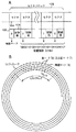
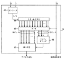
図1Aは本発明の第1の実施の形態における光ディスクの構成図であり、Bはセクタの配列を示した説明図である。図1Aにおいて101は光ディスク基板、102はディスク製造時にあらかじめ形成されたヘッダ部、103は情報の記録が可能な記録部、104はデータの情報単位であるセクタを表す。図1Bにおいて105は所定数、たとえば32個、のセクタを1単位とするセクタブロックを表す。
光ディスク基板101には光学的にアモルファス、クリスタルというように相状態を変化させて記録し、再生時には反射率差によって信号を読み取る相変化膜があらかじめ形成されている。
次に、図2Aを用いてセクタ104とセクタブロック105の関係を詳細に説明する。
Hereinafter, embodiments of the present invention will be described with reference to the drawings.
(Embodiment 1)
FIG. 1A is a configuration diagram of an optical disc according to the first embodiment of the present invention, and B is an explanatory diagram showing an arrangement of sectors. In FIG. 1A, 101 denotes an optical disk substrate, 102 denotes a header portion formed in advance at the time of manufacturing the disc, 103 denotes a recording portion capable of recording information, and 104 denotes a sector which is a data information unit. In FIG. 1B, 105 represents a sector block having a predetermined number, for example, 32 sectors as one unit.
The
Next, the relationship between the
本実施の形態の光ディスクは、トラックが、連続するセクタブロック105によって構成されている。上述したようにそれぞれのセクタブロック105は32個のセクタ104から構成され、各セクタ104の構成は、先頭部分にヘッダ部102が存在し、信号の記録再生が行われる記録部103がさらに続く。また、1セクタの長さは、2448バイトとする。
各セクタブロック105において、先頭に配置されたセクタ104のヘッダ部102には同期マーク「S」が設けられている。この同期マーク「S」を検出することによって、セクタブロック105の先頭を検出可能としている。
In the optical disk of the present embodiment, a track is composed of continuous sector blocks 105. As described above, each
In each
次に、そのセクタブロック105内の2番目に配置されたセクタ104のヘッダ部102には、正マークまたは負マークが設けられている。ここで、正マークを「1」、負マークを「0」という情報を割り当てる。図2Aに示す例においては、2番目に配置されたセクタ104のヘッダ部には負マーク「0」が割り当てられている。このように、2番目以降の各セクタ104(後続セクタという)のヘッダ部にそれぞれ1ビットの情報を加えることができる。
Next, the
このように、セクタブロック105に含まれる32個のセクタのヘッダ部の情報をまとめると、同期マーク「S」および、これに続く正マーク「1」または負マーク「0」からなる31ビットの情報を生成することができる。逆に言えば、セクタブロック105毎に31ビットの情報を1ビット毎に分割し、31個のセクタ104に分散させて配置し、その先頭にさらにセクタブロック105の先頭を検出するために同期マークを配置した構成である。このように0、1を分散して配置したアドレスを分散アドレスという。
As described above, when the information of the header portions of the 32 sectors included in the
ここで、上述した31ビットの情報は、19ビットを主情報、12ビットを副情報とする。この19ビットの主情報をセクタブロック105の位置情報とする。このとき、2の19乗=524288個のセクタブロック105の位置検出が可能である。したがって、光ディスク全体において先頭セクタブロックのアドレスを0とし、以降に続くセクタブロック毎に位置情報が1ずつ増す情報を割り当て、19ビットの主情報をセクタブロック105の絶対位置情報とすると、例えば、セクタ104は2048バイトの情報を有し、セクタブロック105は65536(=2048×32)バイトの情報を有するとすれば、19ビットの位置情報によって最大34ギガバイトのデータにアクセスできる位置情報の割り当てが可能である。
Here, the 31-bit information described above has 19 bits as main information and 12 bits as sub-information. This 19-bit main information is used as position information of the
一方、12ビットの副情報は、19ビットの主情報および12ビットの副情報の任意のビットがディフェクト等で欠落したり、再生時に誤って検出した場合でも訂正が可能なエラー訂正符号を割り当てる。これは、例えば31ビット全情報のエラー訂正符号とする。また、セクタブロック105の位置情報は連続するセクタブロック105で1ずつ増す情報なので、上位の情報は先行のセクタブロック105から予測可能であることから、例えば下位8ビットのエラー訂正符号としても構わない。
分散アドレスについては、特願平11−343060にさらに詳しい説明がある。
On the other hand, the 12-bit sub information is assigned an error correction code that can be corrected even if any bits of the 19-bit main information and the 12-bit sub information are lost due to a defect or are erroneously detected during reproduction. This is, for example, an error correction code for all 31-bit information. Further, since the position information of the
The distributed address is further described in Japanese Patent Application No. 11-343060.
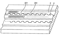
図2B示すように、本発明においては、光ディスク101は、らせん状または同心円状(実施の形態ではらせん状)の複数のトラックを有し、トラック上にセクタが配置されている。図1Aの例では、半径方向の仮想線(点線)に沿って、仮想線上のみでヘッダ部(同期マーク「S]、正マーク「1」、負マーク「0」のいずれかを含む)が並んでいる例が示されているが、図2Bに示すように、どの半径方向においてもヘッダ部が並ばないようにするのが好ましい。
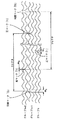
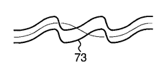
また、図3に示すようにトラックは、グルーブで形成され、隣接するトラックの間、たとえばグルーブnとグルーブn+1の間はランドになっている。ランドは、ミラーで形成されている。グルーブは、波状に蛇行するウォブル形状になっており、一例では、1セクタ当たり153サイクルのウォブル波が存在する。この場合、ウォブルの周期は16バイトとなる。 記録されるデータが8−16変調で記録される場合、1クロック長をTで表せば、最短マークは3T、最長マークは14Tとなる。また、1バイト=16Tで表せる。
As shown in FIG. 2B, in the present invention, the
Further, as shown in FIG. 3, the track is formed by a groove, and a land is formed between adjacent tracks, for example, between the groove n and the
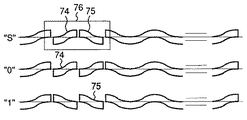
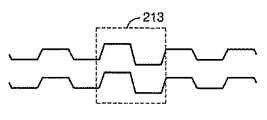
また、本実施の形態においては、図3に示すように、正マーク「1」はトラック方向に伸びる幅W1の第1グルーブ不連続部で形成され、負マーク「0」はトラック方向に伸びる幅W0の第2グルーブ不連続部で形成され、同期マーク「S」はトラック方向に伸びる幅Wsの第3グルーブ不連続部で形成される。これらのグルーブ不連続部は、ランドにおけるミラー部と同様のミラー構成となっている。
同期マーク「S」は、光ディスクの半径方向に並べる必要がない。他のマークも同様である。したがって、セクタ長をディスクのどの位置においても同じ長さとすることが出来るので、完全なCLVを達成することが出来る。
また、グルーブ不連続点の直後から記録を開始することが出来るので、記録開始点を精度高く得ることが出来る。
Further, in the present embodiment, as shown in FIG. 3, the positive mark “1” is formed by the first groove discontinuous portion having the width W1 extending in the track direction, and the negative mark “0” is the width extending in the track direction. The synchronization mark “S” is formed by a third groove discontinuity having a width Ws extending in the track direction. These groove discontinuous portions have the same mirror configuration as the mirror portion in the land.
The synchronization mark “S” does not need to be arranged in the radial direction of the optical disc. The same applies to the other marks. Therefore, since the sector length can be the same at any position on the disk, complete CLV can be achieved.
Further, since recording can be started immediately after the groove discontinuity point, the recording start point can be obtained with high accuracy.
このようなグルーブ不連続部による同期マーク、正マーク、負マークは、次のようにして形成される。
グルーブが形成される前の光ディスクは、全面ミラー仕上げの上にフォトレジストが塗布された構成となっている。この光ディスクを回転させ、トラックに直行して振動するレーザ光を当てると、ウォブルするグルーブが形成される。グルーブ形成中にレーザ光が中断されると、中断された時間長さに応じてグルーブが不連続となり、同期マーク「S」、正マーク「1」または負マーク「0」が形成される。好ましい実施の形態においては、同期マーク「S」、正マーク「1」、負マーク「0」のいずれもウォブルグルーブの山または谷、すなわち振幅最大部において形成され、かかるグルーブ不連続部の検出を容易にしている。このように、グルーブ不連続部でマークを形成するので、1ビームのレーザ光でカッティングが可能となる。
Such synchronization marks, positive marks, and negative marks due to the groove discontinuities are formed as follows.
The optical disk before the groove is formed has a structure in which a photoresist is applied on the entire mirror finish. When this optical disk is rotated and a laser beam that oscillates perpendicular to the track is applied, a wobbled groove is formed. When the laser beam is interrupted during the groove formation, the groove becomes discontinuous according to the interrupted time length, and the synchronization mark “S”, the positive mark “1”, or the negative mark “0” is formed. In the preferred embodiment, all of the synchronization mark “S”, the positive mark “1”, and the negative mark “0” are formed in the peak or valley of the wobble groove, that is, the maximum amplitude portion, and detection of such a groove discontinuity portion is performed. Making it easy. In this way, since the mark is formed at the groove discontinuous portion, cutting can be performed with one beam of laser light.
同期マーク「S」、正マーク「1」、負マーク「0」に対応するグルーブ不連続部のそれぞれの幅Ws、W1、W0は次のようにして決められる。
トラッキングエラー信号にノイズとして漏れ込む記録データ信号を、分散アドレス信号のひとつ、すなわち同期マーク「S」、正マーク「1」、負マーク「0」のいずれかの信号と誤認混同しないため、記録データに含まれる最長マーク長以上(上述の例では14T以上)にマーク幅を選択することが好ましい。
また、同期マーク「S」、正マーク「1」、負マーク「0」は、いずれもウォブルの振幅最大点に配置され、そのためにはマーク幅をウォブル周期の1/2未満にする必要があり、検出制度を上げるためには、ウォブル周期の1/4以下にすることが好ましい。
The widths Ws, W1, and W0 of the groove discontinuities corresponding to the synchronization mark “S”, the positive mark “1”, and the negative mark “0” are determined as follows.
The recording data signal that leaks into the tracking error signal as noise is not mistakenly mixed with one of the distributed address signals, that is, the synchronization mark “S”, the positive mark “1”, or the negative mark “0”. It is preferable to select a mark width equal to or longer than the longest mark length included in (in the above example, 14T or longer).
In addition, the synchronization mark “S”, the positive mark “1”, and the negative mark “0” are all arranged at the maximum wobble amplitude. For this purpose, the mark width needs to be less than ½ of the wobble period. In order to improve the detection system, it is preferable to set it to 1/4 or less of the wobble period.
以上により、同期マーク「S」、正マーク「1」、負マーク「0」のいずれのグルーブ不連続部の幅Wについては、
14T<W<ウォブル周期の1/2 (1)
好ましくは
14T<W<ウォブル周期の1/4 (2)
にすることが好ましい。この(1)、(2)の条件を満たし、同期マーク「S」、正マーク「1」、負マーク「0」を表すグルーブ不連続部の幅を識別しやすい比率、たとえば4:2:1で設定する。いずれのグルーブ不連続部の比率を4にしてもよいが、識別が最も重要な同期マーク「S」に対応する第3グルーブ不連続部の比率を4とし、正マーク「1」に対応するものを2(又は1)とし、負マーク「0」に対応するものを1(又は2)とする。グルーブ不連続部の幅の具体的な一例として、
第3グルーブ不連続部(同期マーク「S」)=4バイト、
第1グルーブ不連続部(正マーク「1」)=2バイト、
第2グルーブ不連続部(負マーク「0」)=1バイト
とする。以上のように、グルーブ不連続部は、単にかかるグルーブ不連続部が有るか無いかをあらわしているのではなく、グルーブ不連続部の長さにより、3種類の異なった意味(正マーク「1」、負マーク「0」、同期マーク「S」)を表す。
From the above, regarding the width W of the groove discontinuity portion of any of the synchronization mark “S”, the positive mark “1”, and the negative mark “0”,
14T <W <1/2 of the wobble cycle (1)
Preferably 14T <W <1/4 of wobble period (2)
It is preferable to make it. A ratio that satisfies the conditions (1) and (2) and easily identifies the width of the groove discontinuity representing the synchronization mark “S”, the positive mark “1”, and the negative mark “0”, for example, 4: 2: 1. Set with. The ratio of any groove discontinuity may be 4, but the ratio of the third groove discontinuity corresponding to the synchronization mark “S” that is most important for identification is 4, and it corresponds to the positive mark “1”. Is 2 (or 1), and the one corresponding to the negative mark “0” is 1 (or 2). As a specific example of the width of the groove discontinuity,
Third groove discontinuity (synchronization mark “S”) = 4 bytes,
First groove discontinuity (positive mark “1”) = 2 bytes,
The second groove discontinuity (negative mark “0”) = 1 byte. As described above, the groove discontinuity does not simply indicate whether or not such a groove discontinuity exists, but has three different meanings (positive mark “1” depending on the length of the groove discontinuity. ”, Negative mark“ 0 ”, synchronization mark“ S ”).
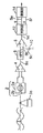
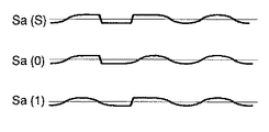
図4は、図3に示す分散アドレスの読取装置を示し、図5は読取装置の主要点における出力信号の波形図を示す。図4において、2はレーザ光を放射する発光素子2cとトラック方向に2分割された受光素子2a、2bからなる光ヘッド、4は受光素子2a、2bからの信号の差を取り、差信号Sa(図5)を出力する減算器、6は高周波成分を通過させグルーブ不連続部信号Sb(図5)を出力するハイパスフィルタ、8はグルーブ不連続部信号Sbを、閾値設定器10からの所定の閾値Sc(図5)と比較し、2値化されたグルーブ不連続部信号Sd(図5)を出力する比較器、12は2値化されたグルーブ不連続部信号Sdを第1グルーブ不連続部(正マーク「1」)、第2グルーブ不連続部(負マーク「0」)、第3グルーブ不連続部(同期マーク「S」)のいずれに該当するかを判別する判別器、14は同期マーク「S」以降の31ビットの正マーク「1」および負マーク「0」を順次集め、分散アドレスを連続アドレスにそろえる復調器である。減算器4から出力される差信号Saは、プッシュ−プル信号であるので、トラッキングエラー信号を利用してもよい。
FIG. 4 shows the distributed address reader shown in FIG. 3, and FIG. 5 shows a waveform diagram of output signals at the main points of the reader. In FIG. 4, 2 is an optical head composed of a
図5に示すように、差信号Saは、トラックのウォブルに従って正弦波を描く。グルーブ不連続部がある場所では、差信号Saはゼロになるので、グルーブ不連続部の幅に応じたパルス幅でゼロレベルが出力される。ウォブルの正弦波である低域波成分をフィルタ8で除去したグルーブ不連続部信号Sbは、グルーブ不連続部によるパルスのみが存在する。このパルスを所定の閾値と比較し、2値化されたグルーブ不連続部信号Sd生成する。
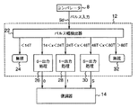
図6は、判別器12の詳細を示す。22は2値化されたグルーブ不連続部信号Sdを受け、信号Sdのパルス幅を検出するパルス幅検出器である。検出された信号Sdのパルス幅が14T以下であれば無視処理部24に送られ、その信号は無視される。
As shown in FIG. 5, the difference signal Sa draws a sine wave according to the wobble of the track. Since the difference signal Sa is zero at a location where there is a groove discontinuity, a zero level is output with a pulse width corresponding to the width of the groove discontinuity. The groove discontinuity signal Sb obtained by removing the low-frequency wave component which is a wobble sine wave by the filter 8 includes only a pulse due to the groove discontinuity. This pulse is compared with a predetermined threshold value, and a binarized groove discontinuity signal Sd is generated.
FIG. 6 shows details of the
検出された信号Sdのパルス幅が14T以上で24T以下であれば0−出力処理部26に送られ、第2グルーブ不連続部信号であることが認識され、「0」を表す信号Se(図5)が出力される。信号Seは次のグルーブ不連続部信号Sdによりリセットされる。
検出された信号Sdのパルス幅が24T以上で48T以下であれば1−出力処理部28に送られ、第1グルーブ不連続部信号であることが認識され、「1」を表す信号Sf(図5)が出力される。信号Sfは次のグルーブ不連続部信号Sdによりリセットされる。
検出された信号Sdのパルス幅が48T以上で80T以下であればS−出力処理部30に送られ、第3グルーブ不連続部信号であることが認識され、セクタブロックの先頭を表す信号「S」が出力される。信号「S」は次のグルーブ不連続部信号Sdによりリセットされる。
If the detected signal Sd has a pulse width of 14T or more and 24T or less, the signal Sd is sent to the 0-
If the detected signal Sd has a pulse width of 24T or more and 48T or less, the signal Sd is sent to the 1-
If the pulse width of the detected signal Sd is 48T or more and 80T or less, it is sent to the S-
検出された信号Sdのパルス幅が80T以上であれば無視処理部32に送られ、その信号は無視される。言うまでもなく、「0」を表す信号Seは負マーク「0」に対応し、「1」を表す信号Sfは正マーク「1」に対応し、信号「S」は同期マーク「S」に対応する。
0−出力処理部26からの「0」を表す信号Se、1−出力処理部28からの「1」を表す信号Sf、S−出力処理部30からの信号「S」は復調器14に送られ、分散アドレスが一つのアドレスとして認識される。
以上のように、判別器12では、グルーブが有るか無いかの判別ではなく、グルーブ不連続部信号の長さにより、3種類の異なった意味の信号(「1」を表す信号Sf、「0」を表す信号Se、「S」を表す信号)が生成される。
If the detected signal Sd has a pulse width of 80T or more, it is sent to the ignore processing
The signal Se representing “0” from the 0-
As described above, the
図7は復調器14の詳細を示す。42は信号Seを1ビット信号「0」に、信号Sfを1ビット信号「1」に変換するエンコーダ、44はエンコーダ42からの1ビット信号「0」または「1」を順次受け、31ビットのシリアルな分散アドレスをパラレルに変換するシフトレジスタ、46は信号「S」に応答してシフトレジスタ44に並べられた31ビットのアドレス信号を保持するラッチ、48は31ビットの下位12ビットをパリティチェック用のコードに利用するためのパリティコーダ、50はパリティチェック用のコードを用いて31ビットの上位19ビットのアドレスのエラー訂正を行う誤り訂正処理部である。このようにして復調器14から、各セクタブロックに対する19ビットのアドレスが出力される。
なお、グルーブは、光ディスクの種類により凹部になっている場合もあれば、凸部になっている場合もある。また、ミラー部等で構成されるヘッダ部102は、後からデータの書き込みも可能である。
FIG. 7 shows details of the
The groove may be a concave portion or a convex portion depending on the type of the optical disk. In addition, data can be written later in the
以上説明したアドレス読取装置は、簡単な構成で、効率よく分散アドレスを読み取ることが可能である。また、同期マーク、正マーク負マークの読取は,差信号を用いて行われるので、グルーブ上に記録された情報信号との分離が容易となる。
また、同期マーク、正マーク、負マークは、ウォブルの最大振幅の幅以内に収まっているので、隣接トラック間のクロストークが増大することは無い。
また、光ディスクの内周側と外周側とにおいてセクタの長さを変えることなくセクタが配列され、またセクタブロックの区切れ目を光ディスクの半径方向にそろえる必要が無いので、完全CLVを達成することが出来る。図1Aに示すゾーンCLVの例のように、ヘッダーを配置したセクタやセクタブロックの区切れ目が、トラック間で一致し、ディスク半径方向に集中配置されている場合、ヘッダー以外の部分とヘッダー部において光ディスクの記録層の光透過率が大きく異なる。光透過率が異なっても、光ディスクの記録面が単層の場合は、問題ないが、光ディスクの記録面が2層またはそれ以上の層で構成される場合は、記録層の透過率の局所変化は、たとえば上層から下層へのクロストークを生じるので好ましくない。その点図2Bに示す例の光ディスクでは、完全CLVが可能であるので、ヘッダー部をディスクの半径方向に集中させる必要が無く、分散配置でき、多層構成の光ディスクにおいても、層間のクロストークを低減できる。
The address reading apparatus described above can read distributed addresses efficiently with a simple configuration. Further, since the synchronization mark and the positive mark / negative mark are read using the difference signal, it is easy to separate from the information signal recorded on the groove.
Further, since the synchronization mark, the positive mark, and the negative mark are within the maximum wobble amplitude, crosstalk between adjacent tracks does not increase.
In addition, since the sectors are arranged without changing the length of the sectors on the inner and outer peripheral sides of the optical disc and it is not necessary to align the sector block breaks in the radial direction of the optical disc, it is possible to achieve complete CLV. I can do it. As in the example of the zone CLV shown in FIG. 1A, when the sector and sector block breaks in which the header is arranged coincide between tracks and are concentrated in the disk radial direction, the portion other than the header and the header portion The light transmittance of the recording layer of the optical disc is greatly different. Even if the light transmittance is different, there is no problem if the recording surface of the optical disc is a single layer, but if the recording surface of the optical disc is composed of two or more layers, the local change in the transmittance of the recording layer Is not preferable because, for example, crosstalk occurs from the upper layer to the lower layer. In that respect, since the optical disk of the example shown in FIG. 2B is capable of complete CLV, it is not necessary to concentrate the header portion in the radial direction of the disk, and can be arranged in a distributed manner. it can.
また、完全CLVにあっては、ゾーンCLVと比べて無駄なスペースを少なくすることが出来るので、ディスクの容量を上げることが出来る。
さらに、グルーブと同期マーク、正マーク、負マークは、1つのビームによりカッティングが可能である。
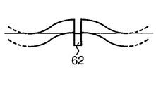
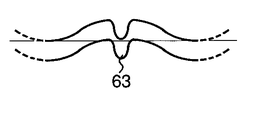
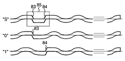
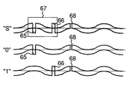
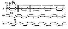
また、以上説明した光ディスクにおいて、グルーブ不連続部は、グルーブを形成するレーザ光を中断して形成するようにしたが、図8、図9に示すようにレーザ光を瞬間的にずらせてグルーブズレ部62または63を形成してもよい。この場合は、ずらす時間幅を調整すればよい。
さらに、本実施の形態では、識別マークはセクタの先頭部分に配置したが、識別マークはセクタの先頭部分で検出する必要はなく、例えばセクタの末尾部分に配置してもかまわない。
Further, in the complete CLV, a useless space can be reduced as compared with the zone CLV, so that the capacity of the disk can be increased.
Further, the groove, the synchronization mark, the positive mark, and the negative mark can be cut by one beam.
In the optical disc described above, the groove discontinuous portion is formed by interrupting the laser beam that forms the groove. However, as shown in FIGS. The
Furthermore, in this embodiment, the identification mark is arranged at the head portion of the sector. However, the identification mark need not be detected at the head portion of the sector, and may be arranged, for example, at the tail portion of the sector.
以上説明したように、第1の実施の形態にかかる光ディスクは、異なった長さのグルーブ不連続部を各セクタの先頭ヘッダ102に形成し、グルーブ不連続部自身に同期マーク「S」、正マーク「1」、負マーク「0」のいずれかの意味を持たせたので、より少ないスペースでセクタブロックのアドレスを与えることが可能となる。
また、本実施の形態の光ディスクは、発光素子2cからのレーザ光が400nm付近の波長を用いた高密度光ディスクに適している。その理由は次の通りである。
As described above, in the optical disc according to the first embodiment, groove discontinuities having different lengths are formed in the
The optical disk of the present embodiment is suitable for a high density optical disk using a laser beam having a wavelength near 400 nm from the
本発明にかかる光ディスクは、記録再生型の光ディスクであり、グルーブ内のディスク表面は結晶状態(非記録状態)にある相変化材料、たとえばゲルマニウム・アンチモン化合物あるいは銀インジウム化合物で構成されている。記録は、所定レベルのレーザ光が照射されると結晶状態(非記録状態)からアモルファス状態(記録状態)に相変化するマークを形成することにより行われる。再生は、より低いレベルのレーザ光を照射し、反射率の異なる結晶状態の部分とアモルファス状態の部分からの反射光の強弱により記録された情報を読み取る。レーザ光が830nmあるいは650nm帯であれば、アモルファス状態(記録状態)の部分からの反射光は、結晶状態(非記録状態)の部分から反射光より弱い。また、ミラー部の反射光は、結晶状態の部分からの反射光より強いので、ミラー部、結晶状態の部分、アモルファス状態の部分からの反射光はそれぞれ、強、中、弱となり、3者の部分の識別は容易である。 The optical disk according to the present invention is a recording / reproducing optical disk, and the disk surface in the groove is made of a phase change material in a crystalline state (non-recording state), for example, a germanium / antimony compound or a silver indium compound. Recording is performed by forming marks that change in phase from a crystalline state (non-recording state) to an amorphous state (recording state) when irradiated with a predetermined level of laser light. Reproduction is performed by irradiating a lower level laser beam and reading information recorded by the intensity of reflected light from the crystalline state portion and the amorphous state portion having different reflectivities. If the laser light is in the 830 nm or 650 nm band, the reflected light from the amorphous state (recording state) portion is weaker than the reflected light from the crystalline state (non-recording state) portion. Also, since the reflected light from the mirror part is stronger than the reflected light from the crystalline part, the reflected light from the mirror part, the crystalline part and the amorphous part becomes strong, medium and weak, respectively. Part identification is easy.
しかし、レーザ光が400nm付近の波長を用いれば、反射率が逆転し、アモルファス状態(記録状態)の部分からの反射光は、結晶状態(非記録状態)の部分からの反射光より強くなる。したがって、ミラー部、結晶状態の部分、アモルファス状態の部分からの反射光はそれぞれ、やや強、中、強となり、ミラー部とアモルファス状態(記録状態)の部分の識別が困難となる。ところが、本実施の形態においては、ミラー部であるグルーブ不連続部の幅を記録マークの幅とは識別可能な幅に設定されているので、記録マークとの識別も容易になる。 However, if the laser light uses a wavelength around 400 nm, the reflectance is reversed, and the reflected light from the amorphous state (recording state) becomes stronger than the reflected light from the crystalline state (non-recording state). Therefore, the reflected light from the mirror portion, the crystal state portion, and the amorphous portion becomes slightly strong, medium, and strong, respectively, and it becomes difficult to distinguish the mirror portion and the amorphous state (recording state) portion. However, in the present embodiment, since the width of the groove discontinuous portion, which is a mirror portion, is set to a width that can be distinguished from the width of the recording mark, it is easy to identify the recording mark.
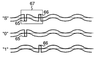
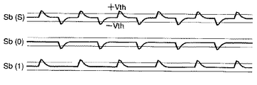
(実施の形態2)
第2の実施の形態においては、図3において示した幅の異なるグルーブ不連続部の変わりに、図10に示すように、グルーブ変形部、すなわちグルーブ下ズレ部65、グルーブ上ズレ部66、およびこの組合せ部67を利用して分散アドレスを付与する。図10に示す例では、グルーブ上ズレ部66単独で正マーク「1」を表し、グルーブ下ズレ部65とそれから所定時間内に現れるグルーブ上ズレ部66の組合せ部67で同期マーク「S」を表し、グルーブ下ズレ部65とそれから所定時間内にグルーブ上ズレ部が現れなければ負マーク「0」を表す。グルーブ下ズレ部、グルーブ上ズレ部を総称して、グルーブズレ部という。部65、部66、組合せ部67のいずれを同期マークにしてもよいし、正マークにしてもよいし、負マークにしてもよいが、検出頻度の少ない同期マークを組合せ部67にするのが好ましい。後に説明する変形例についても同様のことが言える。
(Embodiment 2)
In the second embodiment, instead of the groove discontinuous portions having different widths shown in FIG. 3, as shown in FIG. 10, a groove deformed portion, that is, a groove
グルーブ下ズレ部65はウォブルするグルーブの山のピーク部分からトラックの中心に向かって瞬時的なズレを設けることにより形成する。グルーブ上ズレ部66はウォブルするグルーブの谷のピーク部分からトラックの中心に向かって瞬時的なズレを設けることにより形成する。組合せ部67はウォブルの隣接した山と谷にそれぞれグルーブ下ズレ部65とグルーブ上ズレ部66を形成する。
なお、図10の組合せ部67においては、グルーブ下ズレ部65とグルーブ上ズレ部66は、ウォブル周期の1/2で隣接しているが、ウォブル周期のn+(1/2)倍(nは正の整数)で隣接してもよい。
また、グルーブ下ズレ部は、図8に示すような形態の他、図9に示すような形態で有ってもよい。グルーブ上ズレ部についても同様な形態を取ることが出来る。
The groove
In the
Further, the groove lower shift part may have a form as shown in FIG. 9 in addition to the form as shown in FIG. A similar configuration can be adopted for the groove misalignment.
図11は、図10に示す分散アドレスの読取装置を示し、図12、図13、図14は読取装置の主要点における出力信号の波形図を示す。図11において、図4に示す読取装置と同様な部分は、同様な符号が付されており、その詳細は省略する。2は光ヘッド、4は差信号Sa(図12)を出力する減算器、6はグルーブズレ部信号Sb(図13)を出力するハイパスフィルタ、52はグルーブ上ズレ部信号Sbを、所定の第1閾値+Vth(図13)と比較し、2値化されたグルーブ上ズレ部信号Si(図14)を出力する比較器、54はグルーブ下ズレ部信号Sbを、所定の第2閾値−Vth(図13)と比較し、2値化されたグルーブ下ズレ部信号Sj(図14)を出力する比較器、56は2値化されたグルーブズレ部信号Si、Sjを第1グルーブズレ部(正マーク「1」)、第2グルーブズレ部(負マーク「0」)、第3グルーブズレ部(同期マーク「S」)のいずれに該当するかを判別する判別器、14は分散アドレスを連続アドレスにそろえる復調器である。 FIG. 11 shows the distributed address reader shown in FIG. 10, and FIGS. 12, 13, and 14 show waveform diagrams of output signals at the main points of the reader. 11, the same parts as those of the reading apparatus shown in FIG. 4 are denoted by the same reference numerals, and the details thereof are omitted. 2 is an optical head, 4 is a subtracter that outputs a difference signal Sa (FIG. 12), 6 is a high-pass filter that outputs a groove shift signal Sb (FIG. 13), and 52 is a predetermined first shift signal Sb. Comparator which outputs a binarized groove upper shift part signal Si (FIG. 14) in comparison with 1 threshold value + Vth (FIG. 13), and 54 a groove lower shift part signal Sb, a predetermined second threshold value −Vth ( 13 is a comparator that outputs a binarized groove lower shift signal Sj (FIG. 14), and 56 is a binarized groove shift signal Si, Sj that is a first groove shift (corrected). Mark “1”), a second groove shift portion (negative mark “0”), and a third groove shift portion (synchronization mark “S”), a discriminator for discriminating; It is a demodulator that can be matched.
図12の信号Sa(S)は、グルーブ下ズレ部65とグルーブ上ズレ部66の組合せ部67の差信号を示し、信号Sa(0)は、グルーブ下ズレ部65のみの差信号を示し、信号Sa(1)は、グルーブ上ズレ部66のみの差信号を示す。ウォブルするグルーブの山の部分に下方向のズレ部がある場合は負方向のパルスが生成され、ウォブルするグルーブの谷の部分に上方向のズレ部がある場合は正方向のパルスが生成される。
図13の信号Sb(S)、Sb(0)、Sb(1)は、それぞれ信号Sa(S)、Sa(0)、Sa(1)の低域周波数成分がカットされた波形である。
図14の信号Si(S)、Sj(S)は、それぞれ信号Sb(S)の正方向パルス、負方向パルスを2値化した信号である。信号Sb(S)には正方向パルス、負方向パルスの両方が含まれているので、信号Si(S)、Sj(S)のいずれにもパルスが存在する。信号Sb(0)には負方向パルスしか含まれていないで、信号Si(0)にはパルスが存在せず、信号Sj(0)にパルスが存在する。信号Sb(1)には正方向パルスしか含まれていないで、信号Si(1)にはパルスが存在し、信号Sj(1)にはパルスが存在しない。
判別器56は、次のように動作する。
A signal Sa (S) in FIG. 12 indicates a difference signal of the
Signals Sb (S), Sb (0), and Sb (1) in FIG. 13 are waveforms obtained by cutting the low frequency components of the signals Sa (S), Sa (0), and Sa (1), respectively.
Signals Si (S) and Sj (S) in FIG. 14 are signals obtained by binarizing the positive direction pulse and the negative direction pulse of the signal Sb (S), respectively. Since the signal Sb (S) includes both a positive direction pulse and a negative direction pulse, a pulse exists in both the signals Si (S) and Sj (S). The signal Sb (0) includes only a negative direction pulse, the signal Si (0) has no pulse, and the signal Sj (0) has a pulse. The signal Sb (1) includes only a forward pulse, the signal Si (1) has a pulse, and the signal Sj (1) has no pulse.
The
信号Siまたは信号Sjのいずれか一方のパルスを受けてから所定時間内(ウォブル周期の1/2内)に他方のパルスを受けた場合は同期マーク「S」であることを検出し、同期マーク「S」を表す「S」信号を出力する。この「S」信号は、次のマークが検出されるまで維持される。
信号Siのパルスを受けてから所定時間内(ウォブル周期の1/2内)に信号Sjのパルスが無い場合は、正マーク「1」であることを検出し、正マーク「1」を表す「1」信号を出力する。この「1」信号は、次のマークが検出されるまで維持される。
信号Sjのパルスを受けてから所定時間内(ウォブル周期の1/2内)に信号Siのパルスが無い場合は、負マーク「0」であることを検出し、負マーク「0」を表す「0」信号を出力する。この「0」信号は、次のマークが検出されるまで維持される。
If the other pulse is received within a predetermined time (within 1/2 of the wobble period) after receiving either pulse of the signal Si or signal Sj, the synchronization mark “S” is detected and the synchronization mark is detected. An “S” signal representing “S” is output. This “S” signal is maintained until the next mark is detected.
If there is no pulse of the signal Sj within a predetermined time (within half of the wobble period) after receiving the pulse of the signal Si, the positive mark “1” is detected and “ 1 "signal is output. This “1” signal is maintained until the next mark is detected.
When there is no pulse of the signal Si within a predetermined time (within half of the wobble period) after receiving the pulse of the signal Sj, the negative mark “0” is detected, and “ 0 "signal is output. This “0” signal is maintained until the next mark is detected.
上述の「S」信号、「1」信号、「0」信号は、いずれも図5の下2行に示すような信号であり、図11の判別器56の3本の出力線からそれぞれ出力される。
復調器14は、図7で示した復調器と同様に動作する。
グルーブ下ズレ部65及びグルーブ上ズレ部66は、単にかかるズレ部の有る無しを表すのみならず、上下のズレ方向の情報も含んでいる。従って、信号Si、信号Sjを区別して生成することが可能となる。
また、ウォブル周期の1/2で、グルーブ下ズレ部65、グルーブ上ズレ部66を利用して3種類の意味(「S」、「0」、「1」)を識別可能としている。
また、同期マーク、正マーク、負マークは、ウォブルの最大振幅の幅以内に収まっているので、隣接トラック間のクロストークが増大することは無い。
また、光ディスクの内周側と外周側とにおいてセクタの長さを変えることなくセクタが配列され、またセクタブロックの区切れ目を光ディスクの半径方向にそろえる必要が無いので、完全CLVを達成することが出来る。
また、グルーブと同期マーク、正マーク、負マークは、1つのビームによりカッティングが可能である。
The above-described “S” signal, “1” signal, and “0” signal are all signals as shown in the lower two rows of FIG. 5 and are respectively output from the three output lines of the
The
The groove
Further, at half the wobble cycle, three types of meanings (“S”, “0”, “1”) can be identified using the groove
Further, since the synchronization mark, the positive mark, and the negative mark are within the maximum wobble amplitude, crosstalk between adjacent tracks does not increase.
In addition, since the sectors are arranged without changing the length of the sectors on the inner and outer peripheral sides of the optical disc and it is not necessary to align the sector block breaks in the radial direction of the optical disc, it is possible to achieve complete CLV. I can do it.
Further, the groove, the synchronization mark, the positive mark, and the negative mark can be cut by one beam.
さらに、トラック中心から離れて同期マーク、正マーク、負マークが形成されているので、トラック中心に沿って情報データが記録されても、同期マーク、正マーク、負マークの検出信号に、情報データの信号が混在する程度が少ない。
また、グルーブズレ部をプッシュ−プル信号で検出した場合、差信号は大きな差信号となるので、確実にグルーブズレ部の検出を行うことが可能である。
In addition, since synchronization marks, positive marks, and negative marks are formed away from the track center, even if information data is recorded along the track center, the information data is included in the detection signal of the synchronization mark, positive mark, and negative mark. There is little degree of signal mixing.
Further, when the groove shift part is detected by a push-pull signal, the difference signal becomes a large difference signal, so that the groove shift part can be reliably detected.
(変形例1)
図15から図20までは第2の実施の形態のグルーブ変形部の第1の変形例を示す。
図10においては、グルーブ下ズレ部65、グルーブ上ズレ部66を用いたが、図17の第1の変形例においては、それぞれをグルーブ下り位相反転部74、グルーブ上り位相反転部75に変える。グルーブ下り位相反転部74は、正弦波でウォブルしているグルーブの山から谷までの下り部分、すなわちグルーブの山からウォブル周期の大略1/4の部分、の位相を上下に反転させたものであり、グルーブ上り位相反転部75は、グルーブの谷から山までの上り部分、すなわちグルーブの谷からウォブル周期の大略1/4の部分、の位相を上下に反転させたものである。グルーブ下り位相反転部、グルーブ上り位相反転部を総称してグルーブ位相反転部という。
(Modification 1)
15 to 20 show a first modification of the groove deforming portion of the second embodiment.
In FIG. 10, the groove
図17に示すように、同期マーク「S」は、グルーブ下り位相反転部74とグルーブ上り位相反転部75の両方を連続して含んだもの76で表し、負マーク「0」は、グルーブ下り位相反転部74のみが含まれているもので表し、正マーク「1」は、グルーブ上り位相反転部75のみが含まれているもので表す。マークを表すためのウォブル周期1/4の部分の両端は、図15に示すようにグルーブが不連続になっていてもよいし、図16に示すように急峻に変位するグルーブであってもよい。
これらのマークは図11の読取装置で読み取られる。
As shown in FIG. 17, the synchronization mark “S” is represented by 76 including both the groove down
These marks are read by the reading device shown in FIG.
図18は、図17に示す3つのマークに対応するグルーブ位相反転部の差信号を示す。これらの差信号は、図11の減算器4から得られるものである。差信号Sa(S)より明らかなように、位相が反転してグルーブが上から下に急激に変化している部分では、右下がりに急激に変化する差信号が得られる一方、位相が反転してグルーブが下から上に急激に変化している部分では、右上がりに急激に変化する差信号が得られる。
図19は、差信号をハイパスフィルタ6に通過させた信号を示す。右下がりに急激に変化する差信号は、負方向のパルスとなって現れ、右上がりに急激に変化する差信号は、正方向のパルスとなって現れる。
FIG. 18 shows difference signals of the groove phase inversion units corresponding to the three marks shown in FIG. These difference signals are obtained from the
FIG. 19 shows a signal obtained by passing the difference signal through the high-
図20では、正方向のパルスを比較器52から2値化信号として取り出したものを信号Siで示し、負方向のパルスを比較器54から2値化信号として取り出したものを信号Sjで示している。
この場合、判別器56は、次のように動作する。
信号Siまたは信号Sjのいずれか一方のパルスを受けてから第1所定時間内(ウォブル周期内)に他方のパルスを受けた場合は同期マーク「S」であることを検出し、同期マーク「S」を表す「S」信号を出力する。この「S」信号は、次のマークが検出されるまで維持される。
信号Siのパルスを受けてから第2所定時間内(ウォブル周期の1/2内)に2つ目の信号Siのパルスが続いた場合は、正マーク「1」であることを検出し、正マーク「1」を表す「1」信号を出力する。この場合、さらに、信号Siの最初のパルスを受けてから2つ目のパルスを受けるまでの間、信号Sjのパルスが存在しないことを条件とすることも可能である。この「1」信号は、次のマークが検出されるまで維持される。
In FIG. 20, a signal obtained by extracting a positive pulse from the
In this case, the
When the other pulse is received within the first predetermined time (within the wobble period) after receiving one of the pulses of the signal Si or the signal Sj, the synchronization mark “S” is detected. "S" signal representing "is output. This “S” signal is maintained until the next mark is detected.
If the second pulse of the signal Si continues within the second predetermined time (within half of the wobble period) after receiving the pulse of the signal Si, the positive mark “1” is detected, A “1” signal representing the mark “1” is output. In this case, it is also possible to make it a condition that no pulse of the signal Sj exists between the time when the first pulse of the signal Si is received and the time when the second pulse is received. This “1” signal is maintained until the next mark is detected.
信号Sjのパルスを受けてから第2所定時間内(ウォブル周期の1/2内)に2つ目の信号Sjのパルスが続いた場合は、負マーク「0」であることを検出し、負マーク「0」を表す「0」信号を出力する。この場合、さらに、信号Sjの最初のパルスを受けてから2つ目のパルスを受けるまでの間、信号Siのパルスが存在しないことを条件とすることも可能である。この「0」信号は、次のマークが検出されるまで維持される。
後は上述と同様にして復調器14で処理される。
If the second pulse of the signal Sj continues within the second predetermined time (within half of the wobble period) after receiving the pulse of the signal Sj, the negative mark “0” is detected, A “0” signal representing the mark “0” is output. In this case, it is also possible to make it a condition that no pulse of the signal Si exists between the time when the first pulse of the signal Sj is received and the time when the second pulse is received. This “0” signal is maintained until the next mark is detected.
The subsequent processing is performed by the
グルーブ下り位相反転部74およびグルーブ上り位相反転部75は、単にかかる位相反転部の有る無しを表すのみならず、上り、下りの情報も含んでいる。従って、信号Si、信号Sjを区別して生成することが可能となる。
また、1つのウォブル周期で、グルーブ下り位相反転部74、グルーブ上り位相反転部75を利用して3種類の意味(「S」、「0」、「1」)を識別可能としている。
また、同期マーク、正マーク、負マークは、ウォブルの最大振幅の幅以内に収まっているので、隣接トラック間のクロストークが増大することは無い。
また、光ディスクの内周側と外周側とにおいてセクタの長さを変えることなくセクタが配列され、またセクタブロックの区切れ目を光ディスクの半径方向にそろえる必要が無いので、完全CLVを達成することが出来る。
The groove down
Further, in one wobble cycle, three types of meanings (“S”, “0”, “1”) can be identified using the groove
Further, since the synchronization mark, the positive mark, and the negative mark are within the maximum wobble amplitude, crosstalk between adjacent tracks does not increase.
In addition, since the sectors are arranged without changing the length of the sectors on the inner and outer peripheral sides of the optical disc and it is not necessary to align the sector block breaks in the radial direction of the optical disc, it is possible to achieve complete CLV. I can do it.
また、グルーブと同期マーク、正マーク、負マークは、1つのビームによりカッティングが可能である。
また、ウォブルの最大振幅の位置で位相を反転させているので、同期マーク、正マーク、負マークの位置を精度高く検出することが出来る。
なお、ウォブルの位相を検出して、グルーブ下り位相反転部74、グルーブ上り位相反転部75を検出するようにしてもよい。この場合、位相反転のエッジを検出するよりもSN比が改善される。
Further, the groove, the synchronization mark, the positive mark, and the negative mark can be cut by one beam.
In addition, since the phase is inverted at the position of the maximum amplitude of the wobble, the positions of the synchronization mark, the positive mark, and the negative mark can be detected with high accuracy.
Alternatively, the wobble phase may be detected to detect the groove
(変形例2)
図21から図25までは第2の実施の形態のグルーブ変形部の第2の変形例を示す。
図10においては、グルーブ下ズレ部65、グルーブ上ズレ部66を用いたが、図22の第2の変形例においては、それぞれをグルーブ下り矩形部83、グルーブ上り矩形部84に変える。グルーブ下り矩形部83は、正弦波でウォブルしているグルーブの山から谷までの部分を矩形でつなぐ。すなわちグルーブの山からウォブル周期の大略1/4の部分までを山のレベルでグルーブを形成し、急激に谷のレベルまで変化させ、次のウォブル周期の大略1/4の部分を谷のレベルでグルーブを形成し、ウォブルの谷の部分につなぐ。また、グルーブ上り矩形部84は、正弦波でウォブルしているグルーブの谷から山までの部分を矩形でつなぐ。すなわちグルーブの谷からウォブル周期の大略1/4の部分までを谷のレベルでグルーブを形成し、急激に山のレベルまで変化させ、次のウォブル周期の大略1/4の部分を山のレベルでグルーブを形成し、ウォブルの山の部分につなぐ。グルーブ下り矩形部、グルーブ上り矩形部を総称してグルーブ矩形部という。また、グループ矩形部、グルーブ位相反転部、グルーブズレ部などが含まれる含まれるウォブル波を変形ウォブル波という。
(Modification 2)
FIGS. 21 to 25 show a second modification of the groove deforming portion of the second embodiment.
In FIG. 10, the groove
図22に示すように、同期マーク「S」は、グルーブ下り矩形部83とグルーブ上り矩形部84の両方を連続して含んだもの85で表し、負マーク「0」は、グルーブ下り矩形部83のみが含まれているもので表し、正マーク「1」は、グルーブ上り矩形部85のみが含まれているもので表す。図21にグルーブ下り矩形部83の詳細が示されている。
これらのマークは図11の読取装置で読み取られる。
図23は、図22に示す3つのマークに対応するグルーブ矩形部の差信号を示す。これらの差信号は、図11の減算器4から得られるものである。差信号Sa(S)より明らかなように、グルーブ矩形部が上から下に急激に変化している部分では、右下がりに急激に変化する差信号が得られる一方、グルーブ矩形部が下から上に急激に変化している部分では、右上がりに急激に変化する差信号が得られる。
As shown in FIG. 22, the synchronization mark “S” is represented by 85 including both the groove descending
These marks are read by the reading device shown in FIG.
FIG. 23 shows the difference signal of the groove rectangular portion corresponding to the three marks shown in FIG. These difference signals are obtained from the
図24は、差信号をハイパスフィルタ6に通過させた信号を示す。右下がりに急激に変化する差信号は、負方向のパルスとなって現れ、右上がりに急激に変化する差信号は、正方向のパルスとなって現れる。
図25では、正方向のパルスを比較器52から2値化信号として取り出したものを信号Siで示し、負方向のパルスを比較器54から2値化信号として取り出したものを信号Sjで示している。
この場合、判別器56は、次のように動作する。
信号Siまたは信号Sjのいずれか一方のパルスを受けてから所定時間内(ウォブル周期内)に他方のパルスを受けた場合は同期マーク「S」であることを検出し、同期マーク「S」を表す「S」信号を出力する。この「S」信号は、次のマークが検出されるまで維持される。
FIG. 24 shows a signal obtained by passing the difference signal through the
In FIG. 25, a signal obtained by extracting a positive pulse from the
In this case, the
When the other pulse is received within a predetermined time (within the wobble period) after receiving either pulse of the signal Si or the signal Sj, the synchronization mark “S” is detected. The “S” signal is output. This “S” signal is maintained until the next mark is detected.
信号Siのパルスを受けてから所定時間内(ウォブル周期内)に信号Sjのパルスが無い場合は、正マーク「1」であることを検出し、正マーク「1」を表す「1」信号を出力する。この「1」信号は、次のマークが検出されるまで維持される。
信号Sjのパルスを受けてから所定時間内(ウォブル周期内)に信号Siのパルスが無い場合は、負マーク「0」であることを検出し、負マーク「0」を表す「0」信号を出力する。この「0」信号は、次のマークが検出されるまで維持される。
後は上述と同様にして復調器14で処理される。
グルーブ下り矩形部83およびグルーブ上り矩形部84は、単にかかる矩形部の有る無しを表すのみならず、上り、下りの情報も含んでいる。従って、信号Si、信号Sjを区別して生成することが可能となる。
また、1つのウォブル周期で、グルーブ下り矩形部83、グルーブ上り矩形部84を利用して3種類の意味(「S」、「0」、「1」)を識別可能としている。
When there is no signal Sj pulse within a predetermined time (within the wobble cycle) after receiving the pulse of the signal Si, it is detected that the mark is “1” and the “1” signal representing the mark “1” is sent. Output. This “1” signal is maintained until the next mark is detected.
When there is no signal Si pulse within a predetermined time (within the wobble period) after receiving the pulse of the signal Sj, the negative mark “0” is detected and a “0” signal representing the negative mark “0” is output. Output. This “0” signal is maintained until the next mark is detected.
The subsequent processing is performed by the
The groove down
Further, in one wobble cycle, three types of meanings (“S”, “0”, “1”) can be identified using the groove down
また、同期マーク、正マーク、負マークは、ウォブルの最大振幅の幅以内に収まっているので、隣接トラック間のクロストークが増大することは無い。
また、光ディスクの内周側と外周側とにおいてセクタの長さを変えることなくセクタが配列され、またセクタブロックの区切れ目を光ディスクの半径方向にそろえる必要が無いので、完全CLVを達成することが出来る。
また、グルーブと同期マーク、正マーク、負マークは、1つのビームによりカッティングが可能である。
また、ウォブルの最大振幅に亘って矩形部を設けているので、同期マーク、正マーク、負マークの位置を精度高く検出することが出来る。
さらに、正弦波であるウォブルのゼロクロス点と、矩形部のゼロクロス点は同じ位置にあるので、ウォブルからクロック信号を抽出する際、マークの所においてもクロック信号が乱れない。
Further, since the synchronization mark, the positive mark, and the negative mark are within the maximum wobble amplitude, crosstalk between adjacent tracks does not increase.
In addition, since the sectors are arranged without changing the length of the sectors on the inner and outer peripheral sides of the optical disc and it is not necessary to align the sector block breaks in the radial direction of the optical disc, it is possible to achieve complete CLV. I can do it.
Further, the groove, the synchronization mark, the positive mark, and the negative mark can be cut by one beam.
Further, since the rectangular portion is provided over the maximum wobble amplitude, the positions of the synchronization mark, the positive mark, and the negative mark can be detected with high accuracy.
Further, since the zero cross point of the wobble which is a sine wave and the zero cross point of the rectangular portion are at the same position, the clock signal is not disturbed even at the mark when extracting the clock signal from the wobble.
なお、第2の実施の形態においては、グルーブ変形部の位置が、「S」、「0」、「1」のマークによって異なっているので、記録を開始することが出来る位置が異なる。記録を開始することが出来る位置を統一するため、追加のマークを加えてもよい。たとえば、図10の形態の場合、図26に示すようにグルーブ不連続部68を追加してもよい。すなわちグルーブ不連続部68の検出後に記録を開始するようにすれば、記録の開始位置を統一することが可能となる。
In the second embodiment, since the position of the groove deforming portion differs depending on the marks “S”, “0”, and “1”, the position where recording can be started differs. In order to unify the position where recording can be started, an additional mark may be added. For example, in the case of the configuration shown in FIG. 10, a
(変形例3)
図27から図31までは第2の実施の形態のグルーブ変形部の第3の変形例を示す。
図22においては、ひとつの変形ウォブル波でひとつのマークを表すようにした。具体的には、ひとつのグルーブ下り矩形部83で負マーク「0」を表し、ひとつのグルーブ上り矩形部84で正マーク「1」を表し、ひとつの矩形部ペア85(ひとつのグルーブ下り矩形部83と、ひとつのグルーブ上り矩形部84が含まれる)で同期マーク「S」を表すようにした。
図27に示す第3の変形例においては、変形ウォブル波が繰返し連続して表れるものを用いる。すなわち、図2のセクタブロック105に含まれるひとつのセクタ104のヘッダ部102に、所定の複数サイクル(例えば32サイクル)のウォブル波を存在させる。同期マークの場合は、図27の上段に示す様に、ヘッダ部102に矩形部ペア85が繰返し複数サイクル(例えば32サイクル)存在する。負マーク「0」の場合は、図27の中断に示す様に、ヘッダ部102にグルーブ下り矩形部83が繰返し複数サイクル(例えば32サイクル)存在する。正マーク「1」の場合は、図27の下断に示す様に、ヘッダ部102にグルーブ上り矩形部84が繰返し複数サイクル(例えば32サイクル)存在する。
(Modification 3)
FIGS. 27 to 31 show a third modification of the groove deforming portion of the second embodiment.
In FIG. 22, one mark is represented by one modified wobble wave. Specifically, one groove descending
In the third modification shown in FIG. 27, a wave in which a modified wobble wave appears repeatedly and continuously is used. That is, a predetermined plurality of cycles (for example, 32 cycles) of wobble waves are present in the
さらに別の変形例としては、ヘッダ部102に限らず、記録部103を含めた全セクタ104に亘って変形ウォブル波の繰返しを用いる。一例では、ひとつのセクタに153サイクルのウォブル波が存在するので、153サイクルの全てのウォブル波について、変形ウォブル波を用いる。
具体的には、セクタブロック105の先頭セクタ全域に亘って、矩形部ペア85を含む変形ウォブル波を繰返し153サイクル連続させ、同期情報「S」を矩形部ペア85にもたせる。先頭セクタに続く残りのセクタのそれぞれであって、負情報「0」をもたせる場合は、そのセクタの全域に亘って、グルーブ下り矩形部83を含む変形ウォブル波を繰返し153サイクル連続させる。同残りのセクタであって、正情報「1」をもたせる場合は、そのセクタ全域に亘って、グルーブ上り矩形部84を含む変形ウォブル波を繰返し153サイクル連続させる。
As yet another modification, not only the
Specifically, the deformed wobble wave including the
なお、変形ウォブル波の繰返しは、セクタ全域でなく、セクタのいずれかの部分に複数のサイクルの変形ウォブル波を設けるようにしても良い。また、変形ウォブル波が存在する複数のサイクルは、ひとつおきのサイクルでも良いし、複数サイクルあけてもよい。このようにサイクル間隔を空ければ、サイクル間隔を測定して別の情報を載せることが可能となる。
このように、変形ウォブル波を用いる場合、ウォブル波に沿ってデータの書き込みをすることができるので、同期情報「S」、負情報「0」、正情報「1」を書き込むためのトラックスペースを取る必要は無く、トラックを構成する変形ウォブル波の形状を観測するだけで、情報を取り出すことが可能となる。したがって、同期情報「S」、負情報「0」、正情報「1」は、ヘッダ部102などの特定領域に入れる必要はなく、セクタの任意の個所に入れることが可能となる。
セクタブロックの先頭の検出を確実にするため、図27の上段の先頭に示す様に、先頭のウォブル波内に不連続部86を設ける。この不連続部86は、図27に有るようにウォブル波の上または下のピーク部分(振幅最大部分)に設けても良いし、グループ下り矩形部83やグルーブ上る矩形部84が存在するゼロクロス点(振幅最小部分)に設けても良い。ゼロクロス点あたりに設けた方が、ウォブル波の周波数を検出する際、不連続部86が不要なノイズを起こさないので、好ましい。不連続部を形成する個所の説明は、第1の実施の形態の不連続部についてもあてはまる。
Note that the repetitive deformation wobble wave may be provided in a plurality of cycles of the wobble wave in any part of the sector, not in the entire sector. Further, the plurality of cycles in which the deformed wobble wave exists may be every other cycle or a plurality of cycles. If the cycle interval is free in this way, it is possible to measure the cycle interval and put other information.
As described above, when the modified wobble wave is used, data can be written along the wobble wave. Therefore, a track space for writing the synchronization information “S”, the negative information “0”, and the positive information “1” is provided. There is no need to take the information, and it is possible to extract information only by observing the shape of the deformed wobble wave constituting the track. Therefore, the synchronization information “S”, the negative information “0”, and the positive information “1” do not need to be placed in a specific area such as the
In order to ensure the detection of the head of the sector block, a
なお、図27において、不連続部86は、トラックグルーブを寸断して設けられているため、これに情報を上書きするのは問題がある。グルーブの有り無しで反射光量が大きく異なり、再生信号に対する外乱として作用するからである。そこで、本変形例では不連続部86を含む領域(たとえばブロック85)をVFO記録領域として割り当てている。VFO記録領域とは、これに続く記録情報を再生するためにPLLを引き込ませるための単一周波数信号VFOが記録される領域のことである。VFOであれば、多少の外乱変動があっても局所的なジッタとなるだけであり、直接エラーを引き起こすことはない。さらに、VFOは単一周波数であるから、不連続部86による外乱を周波数分離することも可能である。
In FIG. 27, since the
図31は、図27に示す変形ウォブル波を読み取る読取装置のブロック図である。
図31の読取装置は、矩形部検出器90と、不連続部検出器91と、分布判別器92で構成される。矩形部検出器90は、図11の読取装置の主要部を採用したものである。矩形部検出器90の主要点における信号波形を図28、図29、図30に示す。
図28は、図27に示す3つの変形ウォブル波のそれぞれに対応する差信号を示す。これらの差信号は、図31の減算器4から得られるものである。その動作は、図11で説明した通りである。
図29は、差信号をハイパスフィルタ6に通過させた信号を示す。右下がりに急激に変化する差信号は、負方向のパルスとなって現れ、右上がりに急激に変化する差信号は、正方向のパルスとなって現れる。
FIG. 31 is a block diagram of a reading device that reads the modified wobble wave shown in FIG.
31 includes a rectangular part detector 90, a discontinuous part detector 91, and a distribution discriminator 92. The rectangular part detector 90 employs the main part of the reading device of FIG. Signal waveforms at main points of the rectangular detector 90 are shown in FIG. 28, FIG. 29, and FIG.
FIG. 28 shows difference signals corresponding to the three modified wobble waves shown in FIG. These difference signals are obtained from the
FIG. 29 shows a signal obtained by passing the difference signal through the high-
図30では、正方向のパルスを比較器52から2値化信号として取り出したものを信号Siで示し、負方向のパルスを比較器54から2値化信号として取り出したものを信号Sjで示している。矩形部ペア85が連続する変形ウォブル波の場合は、信号Siと信号Sjの両方に交互にパルスが表れる。これらのパルスは、変形ウォブル波の1サイクルにひとつの割合で表れる。
ひとつのセクタに変形ウォブル波が153サイクルある場合の動作は次の通りである。先頭セクタ(同期情報「S」含まれるセクタ)の場合、信号Siには153のパルス、信号Sjにも153のパルスが表れる。また、後続セクタで負情報「0」が含まれるセクタの場合、信号Siにはゼロのパルス、信号Sjには153のパルスが表れる。さらに、後続セクタで正情報「1」が含まれるセクタの場合、信号Siには153のパルス、信号Sjにはゼロのパルスが表れる。実際には、雑音などにより、パルス数は多くなったり、少なくなったりする。
In FIG. 30, a signal obtained by extracting a positive pulse as a binary signal from the
The operation when there are 153 cycles of the modified wobble wave in one sector is as follows. In the case of the head sector (sector including the synchronization information “S”), 153 pulses appear in the signal Si and 153 pulses appear in the signal Sj. Further, in the case of a sector including negative information “0” in the succeeding sector, a zero pulse appears in the signal Si and a 153 pulse appears in the signal Sj. Further, in the sector where the positive information “1” is included in the succeeding sector, a pulse of 153 appears in the signal Si and a pulse of zero appears in the signal Sj. Actually, the number of pulses increases or decreases due to noise or the like.
図31の不連続部検出器91は、図4の読取装置の主要部を採用したものである。図5で説明したように、不連続部86が検出され、パルスが出力される。なお、不連続部検出器91に設けた減算器4は、加算器に変えても良い。減算器を用いた場合は、ウォブル波のピーク部あたりに不連続部86が有る場合のみ検出可能であるが、加算器を用いた場合は、ウォブル波のピーク部あたりだけでなく、ゼロクロス部あたりにも不連続部86が有っても検出可能である。
図31の分布判別器92について説明する。
分布判別器92は、パルス数積算器93,94、比較器95,96,97、セクタ同期カウンタ98、ラッチ99で構成される。
パルス積算器93,94は、それぞれ信号Si,信号Sjに含まれるパルス数をカウントする。パルス積算器93のカウント値は、比較器95,96,97の入力aに加えられ、パルス積算器94のカウント値は、比較器95,96,97の入力bに加えられる。比較器95は、a>b(aは入力aに加えられるカウント値、bは入力bに加えられるカウント値を表す)の場合で、好ましくはその差が十分大きい場合(すなわちa≫bの場合)に、ハイの信号が出力される。比較器96は、a<bの場合で、好ましくはその差が十分大きい場合(すなわちa≪bの場合)に、ハイの信号が出力される。比較器97は、a≒bの場合で、好ましくはその差が十分小さい場合に、ハイの信号が出力される。
The discontinuous part detector 91 in FIG. 31 employs the main part of the reading apparatus in FIG. As described with reference to FIG. 5, the
The distribution discriminator 92 in FIG. 31 will be described.
The distribution discriminator 92 includes
これらのハイの信号は、ラッチ99に送られる。比較器95からハイの信号を受けた場合は、ラッチ99は、正情報「1」を表す「1」信号を出力する。この「1」信号は、次のセクタの情報が検出されるまで維持される。比較器96からハイの信号を受けた場合は、ラッチ99は、負情報「0」を表す「0」信号を出力する。この「0」信号は、次のセクタの情報が検出されるまで維持される。比較器97からハイの信号を受けた場合は、ラッチ99は、同期情報「S」を表す「S」信号を出力する。この「S」信号は、次のセクタの情報が検出されるまで維持される。
セクタ同期カウンタ98は、同期信号のサイクル数(ウォブル波のサイクル数と同じであるが、ウォブル波の場合は、雑音が含まれ、数が安定していない。)をカウントする。同期信号は、例えば、検出したウォブル信号からPLL回路により作られる。まず、不連続部検出器91からの不連続部検出パルスによりカウント値がゼロにリセットされる。続いて同期信号のサイクル数、すなわち同期パルスをカウントする。上述の例ではひとつのセクタに153のウォブル波サイクルが含まれていたので、153の同期パルスをカウントする毎に、ひとつのリセット信号をパルス数積算器93,94とラッチ99に送る。パルス数積算器93,94ではカウント値がリセットされる。
These high signals are sent to latch 99. When receiving a high signal from the
The
分布判別器92により、ひとつのセクタ内において信号Siに含まれるパルスの数と信号Sjに含まれるパルスの数が比較され、信号Siのパルス数の方が、信号Sjのパルス数より十分に多い場合は、比較器95からハイの信号が出力され、逆に、信号Sjのパルス数の方が、信号Siのパルス数より十分に多い場合は、比較器96からハイの信号が出力される。さらに、信号Siのパルス数と、信号Sjのパルス数とがおよそ等しい場合は、比較器97からハイの信号が出力される。ラッチ99では、比較器95,96,97のいずれかのハイの信号をラッチし、「1」信号または「0」信号または「S」信号を出力する。また、「S」信号により、セクタ同期カウンタ98はプリセットされる。
The distribution discriminator 92 compares the number of pulses included in the signal Si with the number of pulses included in the signal Sj in one sector, and the number of pulses of the signal Si is sufficiently larger than the number of pulses of the signal Sj. In this case, a high signal is output from the
後は上述と同様にして復調器14で処理される。
変形ウォブル波を繰返し設けることにより、「1」信号または「0」信号または「S」信号をより正確に得ることができる。また、変形ウォブル波の内でもグルーブ矩形部が含まれる変形ウォブル波を用いれば、ウォブル波により本来検出すべき同期信号に悪影響を及ぼすことが少ない。
The subsequent processing is performed by the
By repeatedly providing the modified wobble wave, the “1” signal, the “0” signal, or the “S” signal can be obtained more accurately. In addition, if a deformed wobble wave including a groove rectangular portion is used among the deformed wobble waves, the wobble wave is less likely to adversely affect the synchronization signal to be detected.
(変形例4)
図32に変形例4の要部構成図を示す。図32では、ウォブルの振幅が正方向に有る部分の長さと、負方向にある部分の長さを異なる様にして、ウォブルの周波数は変えずにデューティー比が異なるように形成されている。すなわち、図32の180の部分では負方向の振幅の部分が長くなっており、181の部分では正方向の振幅の部分が長くなっている。図32に示されるように負情報「0」のときは180の部分が広く、正情報「1」のときは反対側の181の部分が広くなるようにウォブルを形成する。このようにすれば、負情報、正情報を判別する際、再生信号を微分する必要がなく、クロックタイマーなどを用いてデューティーを計測すればよいので、ノイズの影響を軽減できる。
(Modification 4)
FIG. 32 shows a configuration of the main part of the fourth modification. In FIG. 32, the length of the portion where the amplitude of the wobble is in the positive direction is different from the length of the portion where the wobble amplitude is in the negative direction, and the duty ratio is different without changing the frequency of the wobble. That is, the portion of the negative amplitude in the
(変形例5)
図33に変形例5の要部構成図を示す。図27の変形例では、先頭のウォブル波内に不連続部86を設けたが、図33の変形例では、トラックグルーブを局所的に太くしたマーク212を設ける。このマーク212は、セクタブロックの先頭を見つけるためのもので、ブロックマークとも言う。図33の構成ならばグルーブが寸断され、不連続になることがないので、ブロックマーク上にVFOのみならず種々の情報を記録することができる。結果的にオーバーヘッドを低減することができる。
(Modification 5)
FIG. 33 shows a main part configuration diagram of
(変形例6)
図34に変形例6の要部構成図を示す。図34の変形例ではグルーブウォブルの振幅を局所的に大きくしたブロックマーク213を設ける。図33の変形例5と同様、この構成でもグルーブが寸断されることがなく、ブロックマーク上にVFOのみならず種々の情報を記録することができる。
(Modification 6)
FIG. 34 shows a main configuration diagram of
(変形例7)
図35に変形例7の要部構成図を示す。トラックグルーブの片側のエッジにのみウォブルが設けられたことを特徴とする。これまでの実施の形態や変形例においては、トラックグルーブ上に情報を記録する、いわゆるグルーブ記録形態の光ディスク媒体について述べてきたが、光ディスクはこれ以外に、トラックに沿って、グルーブ上とランド(隣接グルーブで挟まれた領域)上の両方に記録する、いわゆるランドグルーブ記録形態を有するものがある。変形例7はランドグルーブ記録形態への適用例である。
(Modification 7)
FIG. 35 shows a main part configuration diagram of Modification 7. The wobble is provided only at one edge of the track groove. In the embodiments and modifications so far described, the optical disk medium of the so-called groove recording form in which information is recorded on the track groove has been described. However, the optical disk is also arranged along the track and on the land ( Some have a so-called land groove recording form in which recording is performed on both of the regions on the adjacent grooves). Modification 7 is an application example to the land / groove recording mode.
図35において、グルーブの片側のエッジに負情報「0」(221で示される区間)若しくは正情報「1」(231で示される区間)が形成されている。これにより当該グルーブ2とこれに隣接するランド4が同一のアドレスで表記される。情報はランド4、トラックグルーブ2の両方に記録される。このような記録をすることでトラックピッチを狭くすることができ、さらなる高密度化が可能となる。
以上のように本発明は、トラックグルーブに所定形状の蛇行を単位区間内に周期的に設け、しかも前記形状は上記単位区間において一義的に記述される副情報に応じて異なる形状としたことにより、オーバーヘッドを少なく若しくは無しにアドレスを形成することができ、しかも単一周波数のウォブル再生信号を得ることができ、高密度化に適した光ディスク媒体を提供することができる。
In FIG. 35, negative information “0” (section indicated by 221) or positive information “1” (section indicated by 231) is formed at one edge of the groove. As a result, the
As described above, according to the present invention, meandering of a predetermined shape is periodically provided in the unit groove in the track groove, and the shape is different depending on the sub information uniquely described in the unit interval. Thus, an address can be formed with little or no overhead, and a wobble reproduction signal having a single frequency can be obtained, and an optical disk medium suitable for high density can be provided.
本発明は、光ディスク並びに光ディスクのアドレス読取装置及び方法に利用することができる。 INDUSTRIAL APPLICABILITY The present invention can be used for an optical disk and an optical disk address reading apparatus and method.
Claims (3)
トラックに沿って正弦波状にウォブルさせて形成したグルーブと、
トラックに沿って設けたセクタブロックと、
各セクタブロックを複数に分割して設けたセクタと、
各セクタブロックの先頭のセクタに形成した同期マークと、
各セクタブロックの先頭以外のセクタのそれぞれに形成した正マークまたは負マークとからなる光ディスクであって、
該正マークは、トラック方向に第1幅W1でグルーブが不連続となる第1グルーブ不連続部で形成し、
該負マークは、トラック方向に第2幅W0でグルーブが不連続となる第2グルーブ不連続部で形成し、
該同期マークは、トラック方向に第3幅Wsでグルーブが不連続となる第3グルーブ不連続部で形成したことを特徴とする光ディスク。 In a rewritable optical disc having a spiral or concentric track,
A groove formed by wobbled in a sinusoidal shape along the track;
A sector block provided along the track;
Sectors provided by dividing each sector block into a plurality of sectors;
A synchronization mark formed in the first sector of each sector block;
An optical disc composed of a positive mark or a negative mark formed in each sector other than the head of each sector block,
The positive mark is formed by a first groove discontinuous portion having a first width W1 and a discontinuous groove in the track direction,
The negative mark is formed by a second groove discontinuous portion having a second width W0 and a groove discontinuous in the track direction,
The synchronization mark is formed of a third groove discontinuous portion having a third width Ws and a discontinuous groove in the track direction.
前記製造方法を実現するための製造設備、又は、
前記製造方法を実行するためのプログラム、又は、
前記プログラムを電子計算機によって実行可能な形式で格納するための格納媒体。 A manufacturing method for manufacturing the optical disk according to claim 1, or
Manufacturing equipment for realizing the manufacturing method, or
A program for executing the manufacturing method, or
A storage medium for storing the program in a format executable by an electronic computer.
Priority Applications (1)
| Application Number | Priority Date | Filing Date | Title |
|---|---|---|---|
| JP2009282778A JP4712890B2 (en) | 2000-01-14 | 2009-12-14 | Optical disc and optical disc address reading apparatus and method |
Applications Claiming Priority (5)
| Application Number | Priority Date | Filing Date | Title |
|---|---|---|---|
| JP2000006593 | 2000-01-14 | ||
| JP2000006593 | 2000-01-14 | ||
| JP2000187259 | 2000-06-22 | ||
| JP2000187259 | 2000-06-22 | ||
| JP2009282778A JP4712890B2 (en) | 2000-01-14 | 2009-12-14 | Optical disc and optical disc address reading apparatus and method |
Related Parent Applications (1)
| Application Number | Title | Priority Date | Filing Date |
|---|---|---|---|
| JP2001552384A Division JP4458735B2 (en) | 2000-01-14 | 2000-12-27 | Optical disc, address information generation method, optical disc address reading device, and optical disc data writing device |
Publications (2)
| Publication Number | Publication Date |
|---|---|
| JP2010061804A true JP2010061804A (en) | 2010-03-18 |
| JP4712890B2 JP4712890B2 (en) | 2011-06-29 |
Family
ID=26583553
Family Applications (3)
| Application Number | Title | Priority Date | Filing Date |
|---|---|---|---|
| JP2001552384A Expired - Lifetime JP4458735B2 (en) | 2000-01-14 | 2000-12-27 | Optical disc, address information generation method, optical disc address reading device, and optical disc data writing device |
| JP2007277800A Expired - Lifetime JP4448162B2 (en) | 2000-01-14 | 2007-10-25 | Optical disc, optical disc reader and optical disc writing device |
| JP2009282778A Expired - Lifetime JP4712890B2 (en) | 2000-01-14 | 2009-12-14 | Optical disc and optical disc address reading apparatus and method |
Family Applications Before (2)
| Application Number | Title | Priority Date | Filing Date |
|---|---|---|---|
| JP2001552384A Expired - Lifetime JP4458735B2 (en) | 2000-01-14 | 2000-12-27 | Optical disc, address information generation method, optical disc address reading device, and optical disc data writing device |
| JP2007277800A Expired - Lifetime JP4448162B2 (en) | 2000-01-14 | 2007-10-25 | Optical disc, optical disc reader and optical disc writing device |
Country Status (10)
| Country | Link |
|---|---|
| US (7) | US6738342B2 (en) |
| EP (5) | EP1308939B1 (en) |
| JP (3) | JP4458735B2 (en) |
| KR (1) | KR100658863B1 (en) |
| CN (9) | CN1244913C (en) |
| AU (1) | AU2001224037A1 (en) |
| CA (2) | CA2706897A1 (en) |
| DE (3) | DE60041993D1 (en) |
| TW (1) | TW546643B (en) |
| WO (1) | WO2001052250A1 (en) |
Families Citing this family (57)
| Publication number | Priority date | Publication date | Assignee | Title |
|---|---|---|---|---|
| BR0113794C1 (en) * | 2000-08-31 | 2010-01-05 | Matsushita Electric Ind Co Ltd | development applied to optical disc media; on an optical disc player, a method for reproducing an optical disc medium, and a method for recording information on an optical disc medium |
| EP1324320B8 (en) | 2000-09-01 | 2009-02-18 | Panasonic Corporation | Optical disc medium, optical disc playback and recorder |
| JP4511787B2 (en) | 2000-10-03 | 2010-07-28 | パナソニック株式会社 | Multilayer optical disc and method for producing multilayer optical disc |
| CN100454396C (en) | 2000-10-10 | 2009-01-21 | 松下电器产业株式会社 | Optical disc |
| WO2002033699A1 (en) * | 2000-10-19 | 2002-04-25 | Matsushita Electric Industrial Co., Ltd. | Optical disk medium and signal reproduction method |
| US7376056B2 (en) * | 2002-01-21 | 2008-05-20 | Matsushita Electric Industrial Co., Ltd. | Method and apparatus for reading address information from an optical disc medium |
| US7804994B2 (en) * | 2002-02-15 | 2010-09-28 | Kla-Tencor Technologies Corporation | Overlay metrology and control method |
| MXPA04012390A (en) * | 2003-01-23 | 2005-02-25 | Lg Electronics Inc | Recording medium with copy protection information formed in intermittent or alternate wobbled pits and apparatus and methods for forming, recording, and reproducing the recording medium. |
| JP4468942B2 (en) * | 2003-01-23 | 2010-05-26 | エルジー エレクトロニクス インコーポレイティド | Recording medium having selective information, apparatus and method for forming, recording and reproducing data on the recording medium, and apparatus and method for controlling reproduction |
| JP3848266B2 (en) | 2003-01-23 | 2006-11-22 | 株式会社東芝 | Optical disc having wobble track and apparatus and method using the optical disc |
| KR100952949B1 (en) * | 2003-01-24 | 2010-04-15 | 엘지전자 주식회사 | Method for managing a copy protection information of high density optical disc |
| EP1619673A4 (en) * | 2003-04-30 | 2008-10-08 | Ricoh Kk | Information recording method and device, information reproduction method and device, and recording medium |
| US7272087B2 (en) * | 2003-06-26 | 2007-09-18 | Samsung Electronics Co., Ltd. | Circuit and method for detecting address in pre-groove (ADIP) signal in wobble detection system of optical disc apparatus |
| US7539101B2 (en) * | 2004-01-16 | 2009-05-26 | Tian Holdings, Llc | Method for detecting defect signals on a disc |
| CN100385519C (en) * | 2004-02-12 | 2008-04-30 | 远茂光电股份有限公司 | Method for making recordable compact disc and master mask thereof |
| US20050190686A1 (en) * | 2004-03-01 | 2005-09-01 | Wu-Hsuan Ho | Recordable optical disc and method for manufacturing a mother disc thereof |
| US7586831B2 (en) * | 2005-03-21 | 2009-09-08 | Alliance Storage Technologies, Inc. | Amplitude modulated addressing in disk pregroove |
| KR100739749B1 (en) * | 2005-11-03 | 2007-07-13 | 삼성전자주식회사 | Method and apparatus for detecting saw tooth wobble signal |
| US20080062829A1 (en) * | 2006-09-13 | 2008-03-13 | Jin-Bin Yang | Method and apparatus for determining start of user data in one data block of optical disc by detecting sync patterns disposed between two data blocks |
| EP2074617B1 (en) * | 2006-10-16 | 2011-02-23 | Thomson Licensing | Optical storage medium comprising tracks with positive and negative marks, and stampers and production methods for manufacturing of the optical storage medium |
| CN101514909B (en) * | 2008-02-22 | 2011-07-27 | 鸿富锦精密工业(深圳)有限公司 | Optical code disc and corresponding optical encoder |
| US8612050B2 (en) * | 2008-07-29 | 2013-12-17 | Palo Alto Research Center Incorporated | Intelligent product feed system and method |
| US8949701B2 (en) | 2008-09-23 | 2015-02-03 | Agere Systems Inc. | Systems and methods for low latency media defect detection |
| US8243381B2 (en) * | 2008-11-13 | 2012-08-14 | Agere Systems Inc. | Systems and methods for sector address mark detection |
| US9159355B1 (en) * | 2010-01-21 | 2015-10-13 | Marvell International Ltd. | DVD-RAM header or land/groove detection |
| US8566381B2 (en) | 2010-08-05 | 2013-10-22 | Lsi Corporation | Systems and methods for sequence detection in data processing |
| US8237597B2 (en) | 2010-09-21 | 2012-08-07 | Lsi Corporation | Systems and methods for semi-independent loop processing |
| US8566378B2 (en) | 2010-09-30 | 2013-10-22 | Lsi Corporation | Systems and methods for retry sync mark detection |
| US8614858B2 (en) | 2010-11-15 | 2013-12-24 | Lsi Corporation | Systems and methods for sync mark detection metric computation |
| US8498072B2 (en) | 2010-11-29 | 2013-07-30 | Lsi Corporation | Systems and methods for spiral waveform detection |
| US8526131B2 (en) | 2010-11-29 | 2013-09-03 | Lsi Corporation | Systems and methods for signal polarity determination |
| US8411385B2 (en) | 2010-12-20 | 2013-04-02 | Lsi Corporation | Systems and methods for improved timing recovery |
| US8325433B2 (en) | 2011-01-19 | 2012-12-04 | Lsi Corporation | Systems and methods for reduced format data processing |
| US8261171B2 (en) | 2011-01-27 | 2012-09-04 | Lsi Corporation | Systems and methods for diversity combined data detection |
| US8749908B2 (en) | 2011-03-17 | 2014-06-10 | Lsi Corporation | Systems and methods for sync mark detection |
| US8780683B2 (en) * | 2011-04-11 | 2014-07-15 | Panasonic Corporation | Information recording medium, tracking method, and optical information apparatus |
| US8565047B2 (en) | 2011-04-28 | 2013-10-22 | Lsi Corporation | Systems and methods for data write loopback based timing control |
| US8665544B2 (en) | 2011-05-03 | 2014-03-04 | Lsi Corporation | Systems and methods for servo data detection |
| US8874410B2 (en) | 2011-05-23 | 2014-10-28 | Lsi Corporation | Systems and methods for pattern detection |
| US8498071B2 (en) | 2011-06-30 | 2013-07-30 | Lsi Corporation | Systems and methods for inter-track alignment |
| US8669891B2 (en) | 2011-07-19 | 2014-03-11 | Lsi Corporation | Systems and methods for ADC based timing and gain control |
| US8780476B2 (en) | 2011-09-23 | 2014-07-15 | Lsi Corporation | Systems and methods for controlled wedge spacing in a storage device |
| US8773811B2 (en) | 2011-12-12 | 2014-07-08 | Lsi Corporation | Systems and methods for zone servo timing gain recovery |
| US8625216B2 (en) | 2012-06-07 | 2014-01-07 | Lsi Corporation | Servo zone detector |
| US8681444B2 (en) | 2012-06-07 | 2014-03-25 | Lsi Corporation | Multi-zone servo processor |
| US8564897B1 (en) * | 2012-06-21 | 2013-10-22 | Lsi Corporation | Systems and methods for enhanced sync mark detection |
| US9019641B2 (en) | 2012-12-13 | 2015-04-28 | Lsi Corporation | Systems and methods for adaptive threshold pattern detection |
| US9053217B2 (en) | 2013-02-17 | 2015-06-09 | Lsi Corporation | Ratio-adjustable sync mark detection system |
| US9424876B2 (en) | 2013-03-14 | 2016-08-23 | Avago Technologies General Ip (Singapore) Pte. Ltd. | Systems and methods for sync mark mis-detection protection |
| US9275655B2 (en) | 2013-06-11 | 2016-03-01 | Avago Technologies General Ip (Singapore) Pte. Ltd. | Timing error detector with diversity loop detector decision feedback |
| US10152999B2 (en) | 2013-07-03 | 2018-12-11 | Avago Technologies International Sales Pte. Limited | Systems and methods for correlation based data alignment |
| US9129650B2 (en) | 2013-07-25 | 2015-09-08 | Avago Technologies General Ip (Singapore) Pte. Ltd. | Array-reader based magnetic recording systems with frequency division multiplexing |
| US9129646B2 (en) | 2013-09-07 | 2015-09-08 | Avago Technologies General Ip (Singapore) Pte. Ltd. | Array-reader based magnetic recording systems with mixed synchronization |
| US8976475B1 (en) | 2013-11-12 | 2015-03-10 | Lsi Corporation | Systems and methods for large sector dynamic format insertion |
| CN106463147B (en) * | 2014-05-20 | 2019-03-26 | 松下知识产权经营株式会社 | Information recording method, information record carrier and information recording carrier |
| US9224420B1 (en) | 2014-10-02 | 2015-12-29 | Avago Technologies General Ip (Singapore) Pte. Ltd. | Syncmark detection failure recovery system |
| CN111458558B (en) * | 2020-04-03 | 2022-03-29 | 宁波奥克斯电气股份有限公司 | Parameter acquisition method and device, electronic equipment and storage medium |
Citations (5)
| Publication number | Priority date | Publication date | Assignee | Title |
|---|---|---|---|---|
| JPH1145441A (en) * | 1996-09-26 | 1999-02-16 | Sanyo Electric Co Ltd | Recording medium and information recording and reproducing device |
| JPH1196555A (en) * | 1997-09-25 | 1999-04-09 | Pioneer Electron Corp | Errorneous recording detecting method, device therefor, information recording method and device therefor |
| JPH11134781A (en) * | 1997-10-30 | 1999-05-21 | Sanyo Electric Co Ltd | Recording or reproducing device |
| JPH11273089A (en) * | 1998-03-24 | 1999-10-08 | Victor Co Of Japan Ltd | Optical disk, optical disk recording and reproducing device, method of recording and reproducing optical disk, and original disk for optical disk manufacturing device |
| JPH11288518A (en) * | 1998-03-31 | 1999-10-19 | Victor Co Of Japan Ltd | Optical disk, optical disk recording and reproducing device, its method and optical disk original board manufacturing device |
Family Cites Families (33)
| Publication number | Priority date | Publication date | Assignee | Title |
|---|---|---|---|---|
| US4825403A (en) * | 1983-05-16 | 1989-04-25 | Data General Corporation | Apparatus guaranteeing that a controller in a disk drive system receives at least some data from an invalid track sector |
| GB8424948D0 (en) * | 1984-10-03 | 1984-11-07 | Ici Plc | Optical recording medium |
| US4923412A (en) * | 1987-11-30 | 1990-05-08 | Pyramid Industries, Inc. | Terminal end for coaxial cable |
| US5295131A (en) * | 1990-10-02 | 1994-03-15 | Matsushita Electric Industrial Co., Ltd. | Optical information recording disk having embossed clock mark pits and embossed information recording pits |
| US5167532A (en) * | 1991-10-18 | 1992-12-01 | Insulated Wire Incorporated | Captivation assembly of dielectric elements for supporting and retaining a center contact in a coaxial connector |
| JP3581368B2 (en) | 1994-05-31 | 2004-10-27 | ソニー株式会社 | Data recording device |
| JPH08315426A (en) | 1995-05-15 | 1996-11-29 | Ricoh Co Ltd | Optical disk and disk driving device |
| US5835478A (en) * | 1995-06-15 | 1998-11-10 | Sony Corporation | Optical disc having address information for recording and reproducing data at correct positions |
| US5607325A (en) * | 1995-06-15 | 1997-03-04 | Astrolab, Inc. | Connector for coaxial cable |
| US5615205A (en) | 1995-06-28 | 1997-03-25 | International Business Machines Corporation | Bi-level optical media having embossed header format |
| DE69614095T2 (en) | 1995-12-28 | 2002-03-14 | Sony Corp | OPTICAL PLATE |
| JPH09274770A (en) * | 1996-04-03 | 1997-10-21 | Matsushita Electric Ind Co Ltd | Optical disk reproducing device and reproducing method |
| JPH09282667A (en) | 1996-04-08 | 1997-10-31 | Mitsubishi Electric Corp | Optical disk and optical disk device |
| EP0893792B1 (en) * | 1996-04-11 | 2001-02-21 | Matsushita Electric Industrial Co., Ltd. | Optical disc |
| WO1998010415A1 (en) | 1996-09-03 | 1998-03-12 | Philips Electronics N.V. | Information carrier, reading/writing device and reading device for writing and/or reading information blocks |
| EP0930611A4 (en) * | 1996-09-26 | 2003-02-12 | Sanyo Electric Co | Recording medium and its reproducer |
| CN1516131A (en) * | 1996-10-22 | 2004-07-28 | ������������ʽ���� | Information recording medium and playback device capable of expressing magnetic track swinging information |
| AU726012B2 (en) * | 1996-10-23 | 2000-10-26 | Thomas & Betts International, Inc. | Coaxial cable connector |
| US5836461A (en) * | 1997-01-10 | 1998-11-17 | Schulte Corporation | Wire shelf |
| JP3512583B2 (en) | 1997-01-30 | 2004-03-29 | シャープ株式会社 | optical disk |
| JPH10283689A (en) * | 1997-02-07 | 1998-10-23 | Sanyo Electric Co Ltd | Information recording and reproducing device |
| US6039898A (en) | 1997-05-08 | 2000-03-21 | O.M.D. Optical Memory Devices, Ltd. | Optical memory device and a method for manufacturing thereof |
| JPH1125492A (en) | 1997-05-09 | 1999-01-29 | Sony Corp | Preformatting device and method thereof |
| KR100386531B1 (en) * | 1997-06-16 | 2003-12-31 | 가부시끼가이샤 도시바 | A recording / reproducing optical disc having a header arranged in a zigzag pattern and a recording / |
| JPH1196604A (en) * | 1997-07-24 | 1999-04-09 | Sony Corp | Optical recording medium, and manufacture of optical recording medium |
| SG71824A1 (en) * | 1997-07-24 | 2000-04-18 | Sony Corp | Optical recording medium and method of manufacturing optical recording medium |
| EP0939398B1 (en) * | 1998-02-26 | 2008-01-02 | Victor Company of Japan, Ltd. | Optical disc record carrier with wobbled grooves that permit recording on the grooves and lands, apparatus for manufacturing such a record carrier, and recording and/or reproducing apparatus for such a record carrier |
| JPH11273090A (en) * | 1998-03-24 | 1999-10-08 | Victor Co Of Japan Ltd | Optical disk, optical disk recording and reproducing device, method of recording and reproducing optical disk, and original disk for optical disk manufacturing device |
| JP2000149271A (en) | 1998-11-09 | 2000-05-30 | Sony Corp | Disk recording medium, recording device, and reproducing device |
| JP3558265B2 (en) * | 1998-12-14 | 2004-08-25 | 株式会社リコー | Pit signal detection circuit and optical disk drive |
| US6853615B1 (en) * | 1999-06-29 | 2005-02-08 | Koninklijke Philips Electronics N.V. | Optical record carrier |
| EP1098301A2 (en) * | 1999-11-03 | 2001-05-09 | Samsung Electronics Co., Ltd. | Physical identification data addressing method using wobble signal, wobble address encoding circuit, method and circuit for detecting wobble address, and recording medium |
| AU1860101A (en) * | 1999-12-15 | 2001-06-25 | Koninklijke Philips Electronics N.V. | Optical record carrier and scanning device |
-
2000
- 2000-12-27 WO PCT/JP2000/009347 patent/WO2001052250A1/en active Search and Examination
- 2000-12-27 CN CNB008183902A patent/CN1244913C/en not_active Expired - Fee Related
- 2000-12-27 US US10/169,915 patent/US6738342B2/en not_active Ceased
- 2000-12-27 CN CNB2004100559430A patent/CN100440360C/en not_active Expired - Fee Related
- 2000-12-27 CN CN2006100908869A patent/CN1953066B/en not_active Expired - Fee Related
- 2000-12-27 EP EP00987765A patent/EP1308939B1/en not_active Expired - Lifetime
- 2000-12-27 EP EP09152202A patent/EP2073199B1/en not_active Expired - Lifetime
- 2000-12-27 AU AU2001224037A patent/AU2001224037A1/en not_active Abandoned
- 2000-12-27 CN CNA2006100908854A patent/CN1983397A/en active Pending
- 2000-12-27 KR KR1020027008728A patent/KR100658863B1/en active IP Right Grant
- 2000-12-27 EP EP09180190A patent/EP2224436A3/en not_active Withdrawn
- 2000-12-27 CN CNA2004100559426A patent/CN1560862A/en active Pending
- 2000-12-27 CA CA2706897A patent/CA2706897A1/en not_active Withdrawn
- 2000-12-27 EP EP04004460A patent/EP1435609B1/en not_active Expired - Lifetime
- 2000-12-27 US US11/126,378 patent/USRE40639E1/en not_active Expired - Lifetime
- 2000-12-27 CA CA2396780A patent/CA2396780C/en not_active Expired - Lifetime
- 2000-12-27 DE DE60041993T patent/DE60041993D1/en not_active Expired - Lifetime
- 2000-12-27 CN CN200610090888A patent/CN100583248C/en not_active Expired - Lifetime
- 2000-12-27 EP EP04004459A patent/EP1435608B1/en not_active Expired - Lifetime
- 2000-12-27 CN CNB2006100908892A patent/CN100492499C/en not_active Expired - Lifetime
- 2000-12-27 DE DE60012376T patent/DE60012376T2/en not_active Expired - Lifetime
- 2000-12-27 CN CNB2004100559445A patent/CN100380498C/en not_active Expired - Fee Related
- 2000-12-27 DE DE60033703T patent/DE60033703T2/en not_active Expired - Lifetime
- 2000-12-27 JP JP2001552384A patent/JP4458735B2/en not_active Expired - Lifetime
- 2000-12-27 CN CN2006100908873A patent/CN1956066B/en not_active Expired - Lifetime
- 2000-12-28 TW TW089128152A patent/TW546643B/en not_active IP Right Cessation
-
2003
- 2003-05-28 US US10/445,796 patent/US6912185B2/en not_active Expired - Lifetime
- 2003-05-28 US US10/446,018 patent/US6898175B2/en not_active Expired - Lifetime
- 2003-07-10 US US10/615,799 patent/US7068589B2/en not_active Expired - Lifetime
-
2004
- 2004-03-24 US US10/807,389 patent/US7035189B2/en not_active Expired - Lifetime
- 2004-03-24 US US10/807,354 patent/US6999404B2/en not_active Expired - Lifetime
-
2007
- 2007-10-25 JP JP2007277800A patent/JP4448162B2/en not_active Expired - Lifetime
-
2009
- 2009-12-14 JP JP2009282778A patent/JP4712890B2/en not_active Expired - Lifetime
Patent Citations (5)
| Publication number | Priority date | Publication date | Assignee | Title |
|---|---|---|---|---|
| JPH1145441A (en) * | 1996-09-26 | 1999-02-16 | Sanyo Electric Co Ltd | Recording medium and information recording and reproducing device |
| JPH1196555A (en) * | 1997-09-25 | 1999-04-09 | Pioneer Electron Corp | Errorneous recording detecting method, device therefor, information recording method and device therefor |
| JPH11134781A (en) * | 1997-10-30 | 1999-05-21 | Sanyo Electric Co Ltd | Recording or reproducing device |
| JPH11273089A (en) * | 1998-03-24 | 1999-10-08 | Victor Co Of Japan Ltd | Optical disk, optical disk recording and reproducing device, method of recording and reproducing optical disk, and original disk for optical disk manufacturing device |
| JPH11288518A (en) * | 1998-03-31 | 1999-10-19 | Victor Co Of Japan Ltd | Optical disk, optical disk recording and reproducing device, its method and optical disk original board manufacturing device |
Also Published As
Similar Documents
| Publication | Publication Date | Title |
|---|---|---|
| JP4712890B2 (en) | Optical disc and optical disc address reading apparatus and method | |
| KR100796049B1 (en) | Optical disc medium, optical disc playback method and recording method | |
| KR100887037B1 (en) | Optical disc reproducing apparatus | |
| JP2010182412A (en) | Optical disk medium, optical disk system, and optical disk playback method | |
| JP3370319B1 (en) | Optical disc medium, optical disc reproducing device and recording device | |
| JP3370321B1 (en) | Optical disk medium, optical disk reproducing device and recording device | |
| JP3370320B1 (en) | Optical disc medium, optical disc reproducing device and recording device | |
| JP3370322B1 (en) | Optical disc medium, optical disc reproducing device and recording device | |
| JP2003217132A (en) | Optical disk medium, and method and device for reproducing information | |
| JP2005310371A (en) | Optical disk medium and optical disk reading method |
Legal Events
| Date | Code | Title | Description |
|---|---|---|---|
| A621 | Written request for application examination |
Free format text: JAPANESE INTERMEDIATE CODE: A621 Effective date: 20091214 |
|
| A521 | Request for written amendment filed |
Free format text: JAPANESE INTERMEDIATE CODE: A523 Effective date: 20100125 |
|
| TRDD | Decision of grant or rejection written | ||
| A01 | Written decision to grant a patent or to grant a registration (utility model) |
Free format text: JAPANESE INTERMEDIATE CODE: A01 Effective date: 20110222 |
|
| A61 | First payment of annual fees (during grant procedure) |
Free format text: JAPANESE INTERMEDIATE CODE: A61 Effective date: 20110323 |
|
| R150 | Certificate of patent or registration of utility model |
Ref document number: 4712890 Country of ref document: JP Free format text: JAPANESE INTERMEDIATE CODE: R150 |
|
| EXPY | Cancellation because of completion of term |