JP2010061079A - Image forming apparatus - Google Patents
Image forming apparatus Download PDFInfo
- Publication number
- JP2010061079A JP2010061079A JP2008229547A JP2008229547A JP2010061079A JP 2010061079 A JP2010061079 A JP 2010061079A JP 2008229547 A JP2008229547 A JP 2008229547A JP 2008229547 A JP2008229547 A JP 2008229547A JP 2010061079 A JP2010061079 A JP 2010061079A
- Authority
- JP
- Japan
- Prior art keywords
- toner
- image
- transfer
- control
- density
- Prior art date
- Legal status (The legal status is an assumption and is not a legal conclusion. Google has not performed a legal analysis and makes no representation as to the accuracy of the status listed.)
- Granted
Links
Images


Classifications
-
- G—PHYSICS
- G03—PHOTOGRAPHY; CINEMATOGRAPHY; ANALOGOUS TECHNIQUES USING WAVES OTHER THAN OPTICAL WAVES; ELECTROGRAPHY; HOLOGRAPHY
- G03G—ELECTROGRAPHY; ELECTROPHOTOGRAPHY; MAGNETOGRAPHY
- G03G15/00—Apparatus for electrographic processes using a charge pattern
- G03G15/14—Apparatus for electrographic processes using a charge pattern for transferring a pattern to a second base
- G03G15/16—Apparatus for electrographic processes using a charge pattern for transferring a pattern to a second base of a toner pattern, e.g. a powder pattern, e.g. magnetic transfer
- G03G15/169—Apparatus for electrographic processes using a charge pattern for transferring a pattern to a second base of a toner pattern, e.g. a powder pattern, e.g. magnetic transfer with means for preconditioning the toner image before the transfer
Landscapes
- Physics & Mathematics (AREA)
- General Physics & Mathematics (AREA)
- Electrostatic Charge, Transfer And Separation In Electrography (AREA)
- Control Or Security For Electrophotography (AREA)
- Dry Development In Electrophotography (AREA)
Abstract
Description
本発明は、制御用トナー像の濃度が所定値になるように現像装置へのトナー補給を制御する画像形成装置、詳しくはトナー補給による制御が限界に達した際の転写不良を抑制する制御に関する。 The present invention relates to an image forming apparatus for controlling toner replenishment to a developing device so that the density of a control toner image becomes a predetermined value, and more particularly to control for suppressing transfer failure when control by toner replenishment reaches a limit. .
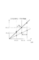
像担持体に所定の静電潜像を形成してトナーで現像して制御用トナー像(カラーパッチ)を形成し、制御用トナー像の濃度を検知して、濃度が所定値に近付くように現像装置へのトナー補給を制御する画像形成装置が実用化されている。所定の静電潜像で形成されるトナー像の濃度が所定値に誘導されることで、転写部における転写媒体(中間転写体又は記録材)に対するトナー像の転写効率を高く維持できるからである(図7参照)。 A predetermined electrostatic latent image is formed on the image carrier and developed with toner to form a control toner image (color patch), and the density of the control toner image is detected so that the density approaches a predetermined value. An image forming apparatus that controls toner supply to a developing device has been put into practical use. This is because the transfer efficiency of the toner image with respect to the transfer medium (intermediate transfer member or recording material) in the transfer portion can be maintained high by inducing the density of the toner image formed by the predetermined electrostatic latent image to a predetermined value. (See FIG. 7).
ところで、トナー像の転写効率を高く維持するためには、転写部に設定される転写条件とトナー像の帯電量との関係を最適に調整する必要がある。このため、転写前帯電装置を設け、像担持体に担持させた画像のトナー像にコロナ放電の荷電粒子を照射して、トナー像の帯電量を、転写媒体への転写に適した水準に調整する技術が実用化されている。また、現像装置内のトナーの帯電量又は像担持体に担持されたトナー像の帯電量を検出して、転写部に印加される定電圧のほうを調整する技術も実用化されている。 By the way, in order to keep the toner image transfer efficiency high, it is necessary to optimally adjust the relationship between the transfer condition set in the transfer portion and the charge amount of the toner image. For this reason, a pre-transfer charging device is provided, and the toner image of the image carried on the image carrier is irradiated with corona discharge charged particles to adjust the charge amount of the toner image to a level suitable for transfer to the transfer medium. This technology has been put into practical use. Further, a technique for adjusting the constant voltage applied to the transfer unit by detecting the charge amount of the toner in the developing device or the charge amount of the toner image carried on the image carrier has been put into practical use.
特許文献1には、制御用トナー像の濃度が所定値になるように、二成分現像剤を用いる現像装置へのトナー補給を制御して、トナー像の帯電量を、転写媒体への転写に適した水準に調整する画像形成装置が示される。ここでは、現像装置内で帯電される二成分現像剤のトナー比率(T/D比)を検出して、T/D比が下限値に達した以降は、制御用トナー像の濃度が所定濃度になるように、トナー像の形成条件を調整する制御に切り替える。T/D比が下限値に達した以降も、トナー補給量に頼って制御用トナー像の濃度を所定濃度に誘導していると、二成分現像剤中のトナーの不足による画像への影響が出てくるからである。 In Patent Document 1, toner replenishment to a developing device using a two-component developer is controlled so that the density of the control toner image becomes a predetermined value, and the charge amount of the toner image is transferred to a transfer medium. An image forming apparatus that adjusts to an appropriate level is shown. Here, after the toner ratio (T / D ratio) of the two-component developer charged in the developing device is detected and the T / D ratio reaches the lower limit value, the density of the control toner image is a predetermined density. Then, the control is switched to the control for adjusting the toner image forming conditions. Even after the T / D ratio reaches the lower limit, depending on the toner replenishment amount, if the density of the control toner image is induced to a predetermined density, the influence on the image due to the shortage of toner in the two-component developer may occur. Because it comes out.
すなわち、画像比率の低い画像の連続形成でトナーやキャリアが劣化すると、トナーの帯電量が減って、所定の中間濃度階調を想定したトナー像形成条件(現像コントラストVcont)で形成される制御用トナー像の濃度が高くなる。このため、トナー補給量を減らしてキャリアとの摩擦機会を増やすことで、トナーの帯電量を回復させて、制御用トナー像の濃度を所定の中間濃度階調へ誘導している。そして、T/D比が下限値の5%に達すると、T/D比を5%に保った状態で、帯電電圧、露光量、現像電圧等を調整して、制御用トナー像の濃度を所定の中間濃度階調へ誘導している。トナーやキャリアの劣化が進んで更にトナー補給量が絞り込まれてT/D比が5%を割り込むと、画像の高濃度部分の現像に支障をきたして濃度不足や濃度ムラが発生し易くなるからである。
特許文献1に示される制御では、T/D比が下限値の5%に達した以降は、帯電量が低下したトナーにより形成された画像のトナー像を中間転写体や記録材に対して最適に転写することが難しくなる。通常範囲のトナー像の帯電量を想定して設定された転写電流では、帯電量が低下したトナー像に必要な転写電荷に対して過剰となるため、転写効率が低下するからである(図7参照)。このため、定着された最終画像の濃度が低下したり色ムラが発生したりする。 In the control disclosed in Patent Document 1, after the T / D ratio reaches 5% of the lower limit, the toner image of the image formed by the toner having a reduced charge amount is optimal for the intermediate transfer member and the recording material. It becomes difficult to transfer to. This is because the transfer current set assuming the charge amount of the toner image in the normal range is excessive with respect to the transfer charge necessary for the toner image having a reduced charge amount, and the transfer efficiency is lowered (FIG. 7). reference). For this reason, the density of the final fixed image is lowered or color unevenness occurs.
本発明は、二成分現像剤のトナー比率が下限値に達した以降も、転写部におけるトナー像の帯電量と転写条件との関係が適正に維持されて転写効率の低下が抑制される画像形成装置を提供することを目的としている。 In the present invention, even after the toner ratio of the two-component developer reaches the lower limit value, the relationship between the charge amount of the toner image in the transfer portion and the transfer condition is properly maintained, and the decrease in transfer efficiency is suppressed. The object is to provide a device.
請求項1の画像形成装置は、像担持体と、前記像担持体に形成された静電潜像をトナーを用いて現像する現像手段と、前記現像手段にトナーを補充するトナー補充手段と、前記現像手段により形成された制御用トナー像を検知する濃度検知手段と、前記現像手段における二成分現像剤中のトナー比率を検出するトナー比率検知手段と、前記像担持体に担持されたトナーを帯電するための帯電手段と、前記帯電手段に印加するバイアスを制御する制御手段とを有するものである。そして、前記トナー比率検知手段により検知されたトナー比率が所定の下限値に達すると、前記トナー補充手段は前記トナー比率が前記下限値を下回らないように前記現像手段にトナーを補充すると共に前記制御手段は前記濃度検知手段による検知結果に基づいて前記帯電手段に印加するバイアスの条件を調整する。 The image forming apparatus according to claim 1, an image carrier, a developing unit that develops the electrostatic latent image formed on the image carrier using toner, a toner replenishing unit that replenishes the developing unit with toner, A density detecting unit for detecting a control toner image formed by the developing unit; a toner ratio detecting unit for detecting a toner ratio in a two-component developer in the developing unit; and a toner carried on the image carrier. It has a charging means for charging and a control means for controlling a bias applied to the charging means. When the toner ratio detected by the toner ratio detecting means reaches a predetermined lower limit value, the toner replenishing means replenishes the developing means with toner so that the toner ratio does not fall below the lower limit value and performs the control. The means adjusts the condition of the bias applied to the charging means based on the detection result by the density detecting means.
請求項4の画像形成装置は、像担持体と、前記像担持体に形成された静電潜像をトナーを用いて現像する現像手段と、前記現像手段にトナーを補充するトナー補充手段と、前記現像手段により形成された制御用トナー像を検知する濃度検知手段と、前記現像手段における二成分現像剤中のトナー比率を検出するトナー比率検知手段と、前記像担持体に担持されたトナーを転写材に転写するための転写部材と、前記転写手段に印加するバイアスを制御する制御手段とを有するものである。そして、前記トナー比率検知手段により検知されたトナー比率が所定の下限値に達すると、前記トナー補充手段は前記トナー比率が前記下限値を下回らないように前記現像手段にトナーを補充すると共に前記制御手段は前記濃度検知手段による検知結果に基づいて前記転写手段に印加するバイアスの条件を調整する。 The image forming apparatus according to claim 4, an image carrier, a developing unit that develops an electrostatic latent image formed on the image carrier using toner, a toner replenishing unit that replenishes the developing unit with toner, A density detecting unit for detecting a control toner image formed by the developing unit; a toner ratio detecting unit for detecting a toner ratio in a two-component developer in the developing unit; and a toner carried on the image carrier. The image forming apparatus includes a transfer member for transferring to a transfer material and a control unit for controlling a bias applied to the transfer unit. When the toner ratio detected by the toner ratio detecting means reaches a predetermined lower limit value, the toner replenishing means replenishes the developing means with toner so that the toner ratio does not fall below the lower limit value and performs the control. The means adjusts the bias condition applied to the transfer means based on the detection result by the density detection means.
本発明の画像形成装置では、トナー比率が所定の下限値に達すると、トナー比率の低下に伴う上述のような問題発生を回避するために、それ以上のトナー比率の低下を阻止するようにトナー補充手段を制御する。その結果、上述したように、転写部における転写条件に対してトナー像の帯電量が適正でなくなるため、転写条件とトナー像の帯電量との少なくとも一方を変化させて、転写条件とトナー像の帯電量との関係を適正化する。 In the image forming apparatus of the present invention, when the toner ratio reaches a predetermined lower limit value, in order to avoid the above-described problem caused by the decrease in the toner ratio, the toner is prevented from further decreasing. Control the replenishment means. As a result, as described above, since the charge amount of the toner image is not appropriate for the transfer condition in the transfer portion, at least one of the transfer condition and the charge amount of the toner image is changed to change the transfer condition and the toner image. Optimize the relationship with the charge amount.
すなわち、請求項1の発明では、帯電手段に印加するバイアスを制御してトナー像の帯電量のほうを転写部の転写条件に合わせ込む。一方、請求項4の発明では、転写手段に印加するバイアスを制御して、逆に転写条件のほうをトナー像の帯電量に合わせ込む。 That is, in the first aspect of the invention, the bias applied to the charging means is controlled so that the charge amount of the toner image is matched with the transfer condition of the transfer portion. On the other hand, in the invention of claim 4, the bias applied to the transfer means is controlled to conversely match the transfer condition with the charge amount of the toner image.
従って、二成分現像剤のトナー比率が下限値に達した以降も、転写部におけるトナー像の帯電量と転写条件との関係が適正に維持される結果、転写効率の低下が抑制されて、トナー像を転写媒体に対して適正に転写できる。 Accordingly, even after the toner ratio of the two-component developer reaches the lower limit, the relationship between the charge amount of the toner image in the transfer portion and the transfer condition is properly maintained, and as a result, the transfer efficiency is prevented from being lowered. The image can be properly transferred to the transfer medium.
以下、本発明のいくつかの実施形態を、図面を参照して詳細に説明する。本発明は、T/D比が下限値に達した以降、トナー像の帯電量と転写電流との少なくとも一方がそれ以前とは異なる限りにおいて、実施形態の構成の一部または全部を、その代替的な構成で置き換えた別の実施形態でも実施できる。 Hereinafter, some embodiments of the present invention will be described in detail with reference to the drawings. According to the present invention, after the T / D ratio reaches the lower limit, as long as at least one of the charge amount and the transfer current of the toner image is different from the previous one, a part or all of the configuration of the embodiment is substituted. Other embodiments replaced with a typical configuration can also be implemented.
本実施形態では、トナー像の形成/転写に係る主要部のみを説明するが、本発明は、必要な機器、装備、筐体構造を加えて、プリンタ、各種印刷機、複写機、FAX、複合機等、種々の用途で実施できる。本実施形態は、温度湿度が30度C80%RHの一定環境下で実験したが、他の温度湿度環境においても、同様の効果を得ることができる。 In the present embodiment, only main parts related to toner image formation / transfer will be described. However, the present invention includes a printer, various printing machines, a copier, a fax machine, a composite machine, in addition to necessary equipment, equipment, and a housing structure. It can be implemented in various applications such as a machine. In this embodiment, the experiment was performed in a constant environment where the temperature and humidity were 30 degrees C80% RH, but similar effects can be obtained in other temperature and humidity environments.
なお、特許文献1に示される画像形成装置の一般的な構成及び制御については、図示を省略して重複する説明を省略する。また、請求項で用いた構成名に括弧を付して示した参照記号は、発明の理解を助けるための例示であって、実施形態中の該当する部材等に構成を限定する趣旨のものではない。 In addition, about the general structure and control of the image forming apparatus shown by patent document 1, illustration is abbreviate | omitted and the overlapping description is abbreviate | omitted. In addition, the reference symbols in parentheses shown in the configuration names used in the claims are examples for assisting understanding of the invention, and are not intended to limit the configuration to the corresponding members in the embodiments. Absent.
<第1実施形態>
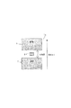
図1は第1実施形態の画像形成装置の構成の説明図である。
<First Embodiment>
FIG. 1 is an explanatory diagram of a configuration of the image forming apparatus according to the first embodiment.
図1に示すように、画像形成装置100は、中間転写ベルト81に沿って、イエロー、マゼンタ、シアン、ブラックの画像形成部Pa、Pb、Pc、Pdを配設したデジタル方式の電子写真画像形成装置である。
As shown in FIG. 1, the
中間転写ベルト81は、駆動ローラ27、テンションローラ28、二次転写内ローラ29に張架して支持され、駆動ローラ27に駆動されて、矢印X方向に300mm/secのプロセススピードで走行する。中間転写ベルト81は、テンションローラ28によって30Nの張架力を付与されている。
The
中間転写ベルト81は、誘電体樹脂等に帯電防止剤としてカーボンブラックを適当量含有させて、体積抵抗率を1×10⁸〜1×10¹³[Ω・cm]に調整してある。誘電体樹脂は、ポリカーボネート、ポリエチレンテレフタレート樹脂フィルム、ポリフッ化ビニリデン樹脂フィルム、ポリイミド、エチレン4フッ化エチレン共重合体等であるが、他の材質を他の体積抵抗率に調整しても構わない。第1実施形態では、中間転写ベルト81は、厚さ80μm、体積抵抗率1×10¹⁰[Ω・cm]の導電性ポリイミド材料を用いた無端状のシームレスベルトである。
The
画像形成部Paでは、感光ドラム1aにイエロートナー像が形成されて中間転写ベルト81に一次転写される。画像形成部Pbでは、感光ドラム1bにマゼンタトナー像が形成されて中間転写ベルト81のイエロートナー像に重ねて一次転写される。画像形成部Pc、Pdでは、それぞれ感光ドラム1c、1dにシアントナー像、ブラックトナー像が形成されて、同様に中間転写ベルト81のトナー像に位置を重ねて順次一次転写される。
In the image forming portion Pa, a yellow toner image is formed on the photosensitive drum 1 a and is primarily transferred to the
中間転写ベルト81に一次転写された四色のトナー像は、二次転写部T2へ給送された記録材Pへ一括二次転写される。二次転写部T2でトナー像を二次転写された記録材Pは、定着装置91で加熱加圧を受けて表面にトナー像を定着された後に外部へ排出される。
The four-color toner images primarily transferred to the
記録材カセット60からピックアップローラ62によって引き出された記録材Pは、レジストローラ61で待機し、中間転写ベルト81のトナー像にタイミングを合わせてレジストローラ61によって二次転写部T2へ給送される。
The recording material P drawn from the
ベルトクリーニング装置50は、中間転写ベルト81にクリーニングブレードを摺擦させて、二次転写部T2を通過した中間転写ベルト81に付着した転写残トナーを除去する。
The
画像形成部Pa、Pb、Pc、Pdは、現像装置23a、23b、23c、23dで使用されるトナーの色がイエロー、マゼンタ、シアン、ブラックと異なる。また、トナー補給槽30a、30b、30c、30dには、イエロー、マゼンタ、シアン、ブラックの未使用トナーが収納されている。しかし、これ以外は、ほぼ同様に構成されるので、以下では、図2を参照して画像形成部Paを説明し、画像形成部Pb、Pc、Pdについては、構成部材に付した参照記号のaを、b、c、dに読み替えて説明されるものとする。
In the image forming portions Pa, Pb, Pc, and Pd, the toner colors used in the developing
<静電像形成手段>
図2は画像形成部の構成の説明図、図3は二次転写部の構成の説明図である。
<Electrostatic image forming means>
FIG. 2 is an explanatory diagram of the configuration of the image forming unit, and FIG. 3 is an explanatory diagram of the configuration of the secondary transfer unit.
図2に示すように、画像形成部Paは、回転可能に配置されたドラム状の電子写真感光体である感光ドラム1aを備えている。感光ドラム1aは、アルミニウム製シリンダの外周面にOPC(有機光半導体)感光層を成膜して直径84mm、長さ350mmに形成されている。感光ドラム1aの中心には支軸を有し、不図示の駆動機構が支軸を中心として感光ドラム1aを矢印R1方向にプロセススピード300mm/secの周速度で回転駆動する。感光ドラム1aの周速度は、他の速度でも構わない。 As shown in FIG. 2, the image forming portion Pa includes a photosensitive drum 1a that is a drum-shaped electrophotographic photosensitive member that is rotatably arranged. The photosensitive drum 1a is formed to have a diameter of 84 mm and a length of 350 mm by forming an OPC (organic optical semiconductor) photosensitive layer on the outer peripheral surface of an aluminum cylinder. The photosensitive drum 1a has a support shaft at the center, and a drive mechanism (not shown) rotates the photosensitive drum 1a in the direction of arrow R1 at a peripheral speed of a process speed of 300 mm / sec around the support shaft. The peripheral speed of the photosensitive drum 1a may be other speed.
感光ドラム1aの周囲には、帯電ローラ22a、現像装置23a、パッチ検センサ24a、転写前帯電装置25a、一次転写ローラ26a、クリーニング装置12a等のプロセス機器が配置されている。
Around the photosensitive drum 1a, process devices such as a charging
帯電ローラ22aは、全体としてローラ状に形成されて、感光ドラム1aに対して平行に配置され、感光ドラム1aの矢印R1方向の回転に伴って従動回転する。帯電ローラ22aは、中心に配置された導電体の芯金の外周にゴム材料の導電層を配置して構成され、芯金の両端部が不図示の軸受部材によって回転自在に支持される。両端部の軸受部材が不図示の押圧バネによって感光ドラム1aに向けて付勢されているので、帯電ローラ22aは、感光ドラム1aの表面に所定の押圧力を持って圧接されている。
The charging
電源D3は、直流電圧に交流電圧を重畳した帯電電圧を帯電ローラ22aの芯金に印加して、感光ドラム1aの表面を、所定の極性、電位に一様均一に接触帯電する。第1実施形態では、温度湿度及び感光ドラム1aの累積使用時間に応じて異なるが、直流電圧700Vにピーク間電圧1500Vppの交流電圧を重畳している。
The power source D3 applies a charging voltage obtained by superimposing an AC voltage on a DC voltage to the core of the charging
露光装置11aは、画像データを展開した画像信号に応じてON−OFF変調されたレーザービームを感光ドラム1aの表面に走査して、感光ドラム101の表面に画像の静電潜像を形成する。
The exposure device 11a scans the surface of the photosensitive drum 1a with a laser beam that is ON-OFF modulated in accordance with an image signal obtained by developing the image data, and forms an electrostatic latent image of the image on the surface of the
<現像手段>
現像装置23aは、帯電極性が正極性の磁性キャリアと帯電極性が負極性の非磁性トナーとを含む二成分現像剤を使用して二成分現像方式により静電潜像を現像する。現像装置23aの内部は、現像スリーブ(現像剤担持体)231a及び供給スクリュー232aが配置された現像室と、攪拌スクリュー233aが配置された攪拌室とに、隔壁によって区画されている。隔壁には、手前側と奥側の端部において、現像室と攪拌室とを相互に連通させる現像剤通路が形成されている。現像スリーブ231aは、表面に二成分現像剤を担持した状態で、中心に固定配置されたマグネットの周囲で回転する。
<Developing means>
The developing
供給スクリュー232a及び攪拌スクリュー233aは、現像スリーブ231aと連動させて回転駆動され、二成分現像剤を、攪拌しつつ相互に軸方向の反対方向に搬送して現像装置23a内を循環させる。現像装置23a内の二成分現像剤は、現像装置23a内を循環する過程で、非磁性トナーと磁性キャリアとが相互に摩擦帯電して、非磁性トナーが負極性、磁性キャリアが正極性に帯電する。
The supply screw 232a and the agitation screw 233a are rotationally driven in conjunction with the developing
帯電した二成分現像剤は、供給スクリュー232aから現像スリーブ231aに供給され、中心のマグネットと磁性キャリアとの間の磁気力によって、現像スリーブ231aの表面に穂立ち状態で担持される。
The charged two-component developer is supplied to the developing
現像スリーブ231aに担持された二成分現像剤は、規制ブレード234aによって層厚を規制され、現像スリーブ231aの回転に伴って、感光ドラム1aと隙間を隔てて対向する現像領域へ搬送される。そして、現像領域において二成分現像剤中のトナーだけが感光ドラム1a上に静電的に移転して、静電潜像をトナー像に現像する。
The two-component developer carried on the developing
現像電源D4は、現像効率、即ち、静電潜像へのトナー付与率を向上させるために、現像スリーブ231aに対して、所定の直流電圧に交流電圧を重畳した振動電圧の現像電圧を印加する。第1実施形態では、温度湿度等に応じて異なるが、直流電圧520Vにピーク間電圧1500Vppの交流電圧を重畳している。
The developing power source D4 applies a developing voltage having an oscillating voltage obtained by superimposing an AC voltage on a predetermined DC voltage to the developing
現像スリーブ231aを通じてトナーが消費されて、トナー濃度(T/D比)が低下した現像室内の二成分現像剤は、供給スクリュー232aに搬送されて攪拌室へ送り込まれる。攪拌スクリュー233aは、トナー搬送スクリュー236aの回転によってトナー補給槽30aから供給された未使用トナーと、既に現像装置23a内にある二成分現像剤とを混合攪拌して、二成分現像剤中のトナー濃度(T/D比)を高めて均一化する。
The two-component developer in the developing chamber in which the toner is consumed through the developing
トナー搬送スクリュー236aによるトナーの供給は、制御部110のCPU101が、補給モータ駆動回路31aを介してトナー搬送スクリュー236aの回転を制御することにより制御される。CPU101に接続されたROM102には、補給モータ駆動回路31aに供給する制御データ等が記憶されている。
The toner supply by the toner conveying screw 236a is controlled by the
パッチ検センサ24aは、感光ドラム1aの軸方向の面内で赤外発光素子から45度の入射角度で赤外光を感光ドラム1aに入射させて、その正反射光を受光素子で検知して反射光強度に応じた8ビット二値データを制御部110に出力する。
The patch detection sensor 24a causes infrared light to be incident on the photosensitive drum 1a at an incident angle of 45 degrees from the infrared light emitting element in the axial plane of the photosensitive drum 1a, and detects the regular reflection light by the light receiving element. 8-bit binary data corresponding to the reflected light intensity is output to the
制御部110は、露光装置11aを制御して、所定濃度階調のトナー像に対応する所定の露光量(レーザービーム強度)で制御用トナー像の静電潜像を感光ドラム1aに書き込み、その後、現像装置23aによって制御用トナー像を現像させる。
The
制御部110は、パッチ検センサ24aの出力を検知して制御用トナー像の濃度を測定し、制御用トナー像の濃度が所定濃度階調に近付くように、二成分現像剤中のトナー濃度(T/D比)を変化させる。
The
攪拌スクリュー233aから供給スクリュー232aへ二成分現像剤が受け渡される位置に、インダクタンスセンサ235aが配置されて、トナー濃度(T/D比)が回復した二成分現像剤の透磁率を検知している。
An
制御部110は、インダクタンスセンサ235aの出力を検知して、二成分現像剤中のトナー濃度(T/D比:磁性キャリア及び非磁性トナーの合計重量(D)に対するトナー重量(T)の割合)を測定する。
The
<転写前帯電装置>
転写前帯電装置25aは、コロナワイヤ251aの感光ドラム1a対向面を除いた周囲を、接地電位に接続されたシールドケースで覆ったコロナ帯電器で構成される。
<Charging device before transfer>
The
帯電器高圧回路32aは、コロナワイヤ251aに、直流電圧に交流電圧を重畳した補助帯電電圧が印加される。第1実施形態では、交流電圧は、ピーク間電圧Vppを7000V一定とし、直流電圧(バイアス)は、定電流制御を用いて可変に設定される。
In the charger
転写前帯電装置25aは、コロナワイヤ251aの周囲で発生させた負極性の荷電粒子を感光ドラム1aに担持された画像のトナー像に照射して、トナー像の帯電量を中間転写ベルト81への転写に適した値に調整する。
The
制御部110は、帯電器高圧回路32aに設定する設定電流値の大きさによって、感光ドラム1aに担持されたトナー像の帯電量(トナー電荷量)を変化させる。
The
<転写電源、二次転写電源>
転写部材である一次転写ローラ26aは、直径8mmの導電体ローラ軸(芯金)の外周面を、円筒状に形成された厚さ4mmの導電性の弾性層で覆って、直径16mmに形成される。弾性層は、ゴム、ウレタン等の高分子エラストマーや高分子フォームにイオン性導電物質を混入して抵抗率を106〜108Ω・cmに調整したものを使用した。しかし、他の材料、他の物性のものを使用しても構わない。転写部材は、中間転写ベルトや記録材搬送ベルトに担持された記録材といった転写材にトナー像を転写するためのものである。
<Transfer power supply, secondary transfer power supply>
The
一次転写ローラ26aは、両端の軸受け部材がバネ部材によって総圧15Nの付勢力で感光ドラム1aに向けて付勢されている。これにより、一次転写ローラ26aは、感光ドラム1a側に中間転写ベルト81を挟み込むように圧接され、中間転写ベルト81と感光ドラム1aとの間に一次転写部T1aが形成される。一次転写ローラ26aの押圧力は、他の押圧力でも構わない。
In the
転写高圧回路(転写電源)33aは、一次転写ローラ26aに正極性の直流電圧(バイアス)を印加して、感光ドラム1aの回転に伴って一次転写部T1aへ搬送されたトナー像を中間転写ベルト81へ一次転写させる。転写高圧回路(転写電源)33aは、一次転写ローラ26aから流れ出す電流が予め設定された設定可能かつ変更可能な電流値(25μA)となるように、一次転写ローラ26aに印加する電圧を定電流制御する。
The transfer high-voltage circuit (transfer power source) 33a applies a positive DC voltage (bias) to the
クリーニング装置12aは、感光ドラム1aにクリーニングブレードを摺擦させて、一次転写部T1aを通過して感光ドラム1aに付着した転写残留トナーを除去する。
The
図3に示すように、二次転写ローラ40は、両端の軸受け部材がバネ部材によって総圧50Nの付勢力で二次転写内ローラ29に向けて付勢されている。これにより、二次転写ローラ29は、二次転写内ローラ29側に中間転写ベルト81を挟み込むように圧接され、二次転写ローラ40と中間転写ベルト81との間に二次転写部T2が形成される。
As shown in FIG. 3, in the
二次転写ローラ40は、直径12mmの導電体ローラ軸(芯金)の外周面に円筒状に形成された導電性の弾性層を配置して、外径24mmに形成されている。弾性層は、ゴム、ウレタン等の高分子エラストマーや高分子フォームにイオン性導電物質を混入することにより、抵抗率を106〜108Ω・cmの中抵抗領域に調整してあるが、他の物性の材料を使用しても構わない。
The
二次転写内ローラ29は、ステンレス、アルミニウム等で形成された直径21mmの導電性のローラであって、接地電位に接続されている。
The secondary transfer
二次転写電源の転写高圧回路41は、二次転写ローラ40の芯金に正極性の直流電圧を印加して、負極性に帯電して中間転写ベルト81に担持されたトナー像を、二次転写部T2を通過する記録材Pへ転写する。ただし、二次転写ローラ40を接地電位に接続して、二次転写内ローラ29に負極性の直流電圧を印加する構成を採用してもよい。
The transfer high-voltage circuit 41 of the secondary transfer power source applies a positive DC voltage to the core of the
二次転写電圧の印加方法は、一次転写電圧と同様に、定電流制御方式とした。転写高圧回路(転写電源)41は、二次転写ローラ40から流れ出す電流が予め設定された設定可能かつ変更可能な電流値(45μA)となるように、二次転写ローラ40に印加する電圧(バイアス)を定電流制御する。二次転写部T2における定電流の設定値が一次転写部T1aより大きい理由は、単色トナー像よりも転写電荷が大きくて転写に要する転写電流が多く必要な二次色トナー像を記録材Pへ一括転写するからである。
The application method of the secondary transfer voltage was a constant current control method, similar to the primary transfer voltage. The transfer high voltage circuit (transfer power source) 41 applies a voltage (bias) applied to the
第1実施形態では、一次転写部T1aと二次転写部T2との両方で、印加する転写電圧の制御を転写電流値で設定可能な定電流制御とした。しかし、転写すべきトナー像の転写電荷に応じた転写電流を設定可能な方式であれば、定電圧方式、その他の方式を採用してもよい。例えば、特開平2−264278号公報に示されるようなATVC(Active Transfer Voltage Control)を用いた定電圧制御を採用してもよい。 In the first embodiment, the control of the transfer voltage applied to both the primary transfer portion T1a and the secondary transfer portion T2 is constant current control that can be set by the transfer current value. However, as long as the transfer current according to the transfer charge of the toner image to be transferred can be set, a constant voltage method or another method may be adopted. For example, constant voltage control using ATVC (Active Transfer Voltage Control) as disclosed in JP-A-2-264278 may be employed.
第1実施形態では、クリーニング装置12a及びベルトクリーニング装置50のクリーニングブレードの材質にポリウレタンゴムを用いて、感光ドラム1a及び中間転写ベルト81との当接圧は10Nとしたが、他の材料、他の当接圧としても構わない。
In the first embodiment, polyurethane rubber is used as the material of the cleaning blades of the
<トナー補充手段>
図4は制御用トナー像の説明図、図5は二成分現像剤中のトナー濃度の所定限界値の説明図である。
<Toner replenishing means>
FIG. 4 is an explanatory diagram of a control toner image, and FIG. 5 is an explanatory diagram of a predetermined limit value of toner density in the two-component developer.
図2に示すように、静電潜像の現像を通じて現像装置23a内の二成分現像剤中のトナー濃度(T/D比)が低下するので、トナー補給槽30から未使用トナーが現像装置23aへ補給される。
As shown in FIG. 2, since the toner concentration (T / D ratio) in the two-component developer in the developing
制御装置110は、感光ドラム1aに制御用トナー像(カラーパッチ)を作像し、パッチ検センサ24aによって制御用トナー像の濃度を検知して、トナー補給槽30からのトナー補充量を制御するパッチ検ATR制御を行う。
The
制御部110は、インダクタンスセンサ235aによって現像装置23a内の二成分現像剤中のトナー濃度(T/D比)を検知して、トナー補給槽30からのトナー補充量を制御する現像剤濃度検知ATR制御を行う。
The
図2を参照して図4に示すように、パッチ検ATR制御では、連続画像形成中、感光ドラム1aにおける画像のトナー像Gの間隔、つまり非画像領域である画像の間隔(所謂紙間)に、制御用トナー像(パッチ画像)Qを形成する。 As shown in FIG. 4 with reference to FIG. 2, in the patch detection ATR control, during continuous image formation, the interval between the toner images G of the image on the photosensitive drum 1a, that is, the interval between the images which are non-image areas (so-called paper interval). Then, a control toner image (patch image) Q is formed.
制御用トナー像Qの静電潜像を「パッチ潜像」と呼ぶ。パッチ潜像は、現像装置23aにより現像されて制御用トナー像となる。パッチ潜像は、常に同じ潜像条件で形成されるため、トナーの帯電量が同じであれば、現像された制御用トナー像のトナー載り量(濃度)は同じになる。
The electrostatic latent image of the control toner image Q is referred to as a “patch latent image”. The patch latent image is developed by the developing
感光ドラム1に担持された制御用トナー像Qの反射光量は、パッチ検センサ24aによって測定される。パッチ検センサ24aは、LED等の発光素子を備える発光部(不図示)と、フォトダイオード(PD)等の受光素子を備える受光部(不図示)とを有しており、発光部から感光ドラム1に入射させた赤外光の正反射光の光量に応じた数値を出力する。パッチ検センサ24aは、感光ドラム1上の制御用トナー像がパッチ検センサ24aの下を通過するタイミングを見計らって、制御用トナー像の反射光量を測定する。 The amount of reflected light of the control toner image Q carried on the photosensitive drum 1 is measured by the patch detection sensor 24a. The patch detection sensor 24a includes a light emitting unit (not shown) including a light emitting element such as an LED and a light receiving unit (not illustrated) including a light receiving element such as a photodiode (PD). A numerical value corresponding to the amount of specularly reflected light of the infrared light incident on 1 is output. The patch detection sensor 24a measures the amount of reflected light of the control toner image by measuring the timing when the control toner image on the photosensitive drum 1 passes under the patch detection sensor 24a.
制御部110は、パッチ検センサ24aの測定結果に係る出力信号を検知して、予め記憶装置102に記録されている濃度変換テーブルを用いてパッチ濃度を計算し、所望のパッチ濃度(反射光量)が得られるトナー補給量を求める。
The
なお、濃度変換テーブルでパッチ濃度として扱われるセンサ出力信号は、制御用トナー像からの正反射光量に対応した値となっているため、値が小さいほど、制御用トナー像のトナー載り量が多く、従ってパッチ濃度は高くなる。例えば、二成分現像剤が新品状態のときのセンサ出力信号が500であって、その後測定したときのセンサ出力信号が400となった場合、新品状態と比較して制御用トナー像Qのトナー載り量が増してパッチ濃度が高くなったことを示している。 Since the sensor output signal treated as the patch density in the density conversion table has a value corresponding to the amount of regular reflection from the control toner image, the smaller the value, the larger the amount of toner applied to the control toner image. Therefore, the patch density is high. For example, when the sensor output signal when the two-component developer is in a new state is 500 and the sensor output signal when measured after that is 400, the toner load on the control toner image Q is compared with the new state. This shows that the patch density is increased as the amount increases.
制御部110は、通常の画像形成中に非画像領域に制御用トナー像Qを形成し、制御用トナー像Qのパッチ濃度を検知して補給トナー量を計算し、出力される画像濃度を随時補正して一定に保つ。
The
制御部110は、形成しようとする画像の画像比率に応じて予測的にトナー補給を制御するビデオカウントATR制御も行う。ビデオカウントATR制御とパッチ検ATR制御とによる合計の補給トナー量Mは、ビデオカウントATR制御による基礎補給量Mvと、パッチ検ATR制御による補給補正量Mpとを加算して式1で求められる。
M=Mv+Mp ・・・(式1)
The
M = Mv + Mp (Formula 1)
補給補正量Mpは、上述のように、新品状態の二成分現像剤での制御用トナー像Qのセンサ出力信号を基準値として、基準値と刻々の測定結果との差分値ΔDから求まる。 As described above, the replenishment correction amount Mp is obtained from the difference value ΔD between the reference value and the momentary measurement result using the sensor output signal of the control toner image Q in the new two-component developer as a reference value.
例えば、新品状態の二成分現像剤による制御用トナー像Qのセンサ出力信号をDs=500とし、その後、X枚目に出力した際に測定した制御用トナー像Qのパッチ濃度をDx=400とすると、差分値ΔD(x)は式2のように求められる。
ΔD(x)=Dx−Ds=−100 ・・・(式2)
For example, the sensor output signal of the control toner image Q by the new two-component developer is set to Ds = 500, and then the patch density of the control toner image Q measured when output to the Xth sheet is set to Dx = 400. Then, the difference value ΔD (x) is obtained as shown in Equation 2.
ΔD (x) = Dx−Ds = −100 (Expression 2)
また、二成分現像剤中のトナー濃度(T/D比)が基準値より1g(基準量)分ずれた時の制御用トナー像Qのセンサ出力信号の変化量ΔD1が定数として記憶装置(ROM)102に記憶され、制御部110は、補給補正量Mpを式3のように求める。
Mp=ΔD(x)/ΔD1 ・・・(式3)
Further, the change amount ΔD1 of the sensor output signal of the control toner image Q when the toner density (T / D ratio) in the two-component developer is shifted by 1 g (reference amount) from the reference value is stored as a constant in the storage device (ROM). ) 102, the
Mp = ΔD (x) / ΔD1 (Formula 3)
制御部110は、感光ドラム1上に静電潜像をデジタル方式で形成しており、基礎補給量Mvは、露光装置11aに出力される画像信号の画像ドットをカウントするビデオカウント処理によって求められる。ビデオカウント値は、記憶装置102に予め記録されているビデオカウント値と補給トナー量との関係を示すテーブルを用いて、基礎補給量Mvへ換算される。こうして、画像形成を行うごとに、各画像の基礎補給量Mvが算出される。
The
制御部110は、感光ドラム1に形成される静電潜像の画素毎のデジタル画像信号に基づく基礎補給量Mvに、パッチ検センサ24aの検知結果に基づく補給補正量Mpを加算してトナー補給動作を制御する。
The
<トナー比率検知手段>
図2に示すように、制御部110は、現像剤濃度検知ATR制御を行って、現在のトナー濃度(T/D比)がトナー補給制御の制限を行う補給制御制限領域に該当するか否かを判断する。
<Toner ratio detection means>
As shown in FIG. 2, the
インダクタンスセンサ235aは、現像装置23a内の供給スクリュー232a近傍に配置されている。インダクタンスセンサ235aは、一定体積中の二成分現像剤の透磁率を検知しているので、二成分現像剤が安定して循環・流動して一定体積の変動が少ない攪拌部近傍に配置される。
The
インダクタンスセンサ235aによる透磁率の検知結果で、予め記憶装置102に記録されているT/D変換テーブルを参照して、現像装置23a内の二成分現像剤のトナー濃度(T/D比)が求められて演算メモリ(RAM)103に保持される。なお、トナー濃度は、二成分現像剤の反射光量を検知して測定してもよい。
The toner concentration (T / D ratio) of the two-component developer in the developing
<制御手段>
図5に示すように、制御部110は、二成分現像剤のトナー濃度(T/D比)、並びに、基礎補給量Mv、補給補正量Mpによって、トナー補給制御を行う。
<Control means>
As shown in FIG. 5, the
トナー濃度T/Dが12%を超える領域Aでは、パッチ検ATR制御の結果として制御用トナー像のパッチ濃度が薄いと判断されても、これ以上トナー濃度(T/D比)を上げると、二成分現像剤のあふれや、かぶり不良などの可能性が高まる。そのため、制御部110は、トナー補給に規制をかけて補給停止とし、トナー濃度(T/D比)が12%以下になるように補給を行う。
In the region A where the toner density T / D exceeds 12%, even if it is determined that the patch density of the control toner image is low as a result of the patch detection ATR control, if the toner density (T / D ratio) is further increased, The possibility of overflow of two-component developer and fogging is increased. Therefore, the
トナー濃度(T/D比)が5%以下の領域Cでは、パッチ検ATR制御の結果として制御用トナー像のパッチ濃度が濃いと判断されても、これ以上トナー濃度(T/D比)を下げると、現像スリーブ231aの現像性能が低下する可能性が高まる。そのため、制御部110は、トナー補給に規制をかけて強制補給とし、トナー濃度(T/D比)が5%を割り込まないように補給を行う。
In the region C where the toner density (T / D ratio) is 5% or less, even if it is determined that the patch density of the control toner image is high as a result of the patch detection ATR control, the toner density (T / D ratio) is further increased. When it is lowered, the possibility that the developing performance of the developing
このように、制御部110は、トナー補給制御に所定のリミットを設けており、トナー濃度(T/D比)の検知結果が所定限界値の12%及び5%をそれぞれ上下に超えた場合に、パッチ検ATR制御によるトナー補給制御を停止する。つまり、パッチ検ATR制御によって通常補給動作が行われる領域Cの外側に、制御用トナー像Qのパッチ濃度をトナー補給制御にフィードバックしない補正制御制限領域(A、C)が設けられている。
In this way, the
言い換えれば、二成分現像剤のトナー濃度(T/D比)は、画像品質を安定化させる上で極めて重要な要素である。しかし、トナー像の帯電量Q/Mは、二成分現像剤中の磁性キャリアの変質や環境の変動により変化して現像性が変化してくる。このため、二成分現像剤中のトナー濃度(T/D比)を一定に維持できても、磁性キャリアの変質や環境の変動があった場合、画像濃度が変化する。 In other words, the toner concentration (T / D ratio) of the two-component developer is a very important factor in stabilizing the image quality. However, the charge amount Q / M of the toner image changes due to the deterioration of the magnetic carrier in the two-component developer and the environmental change, and the developability changes. For this reason, even if the toner concentration (T / D ratio) in the two-component developer can be kept constant, the image density changes when the magnetic carrier is altered or the environment is changed.
パッチ検ATR制御では、感光ドラム上の制御用トナー像のパッチ濃度を一定に保つので、トナーの帯電量Q/Mの増加による現像性の低下によって低いパッチ濃度が検知されるとトナーの補給状態を続けることになる。そのため、現像装置内にトナーが充満して、現像剤のあふれや、かぶりを生じることがある。 In the patch detection ATR control, the patch density of the control toner image on the photosensitive drum is kept constant. Therefore, when a low patch density is detected due to a decrease in developability due to an increase in the toner charge amount Q / M, the toner supply state Will continue. For this reason, the developing device may be filled with toner, causing the developer to overflow or fog.
一方、トナーの帯電量Q/Mの低下による現像性の高まりによって高いパッチ濃度が検知されると、トナーの補給停止状態が続けられることになる。そのため、現像装置内のトナー量の減少により、現像スリーブ上へのトナーコート量が減り(コート不良)、画像劣化を引き起こすことがある。 On the other hand, when a high patch density is detected due to an increase in developability due to a decrease in the toner charge amount Q / M, the toner supply stop state is continued. For this reason, a decrease in the amount of toner in the developing device may reduce the amount of toner coating on the developing sleeve (coating failure) and cause image deterioration.
このような現像剤のあふれや、かぶり、トナーのコート不良は、画像不良として現れるとともに、最悪の場合には画像形成装置本体の性能を損なう可能性がある。 Such developer overflow, fogging, and toner coating failure appear as image defects, and in the worst case, the performance of the image forming apparatus main body may be impaired.
<実施例1>
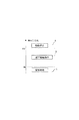
図6は実施例1の制御のタイムチャート、図7はトナー像の帯電量に応じた適正な転写電流の説明図、図8はパッチ濃度とトナー像の帯電量の関係の説明図、図9は転写前帯電装置の電流設定とトナー像の帯電量の関係の説明図である。図10は実施例1の制御による効果の説明図、図11は実施例1の制御のフローチャートである。
<Example 1>
6 is a time chart of the control of the first embodiment, FIG. 7 is an explanatory diagram of an appropriate transfer current according to the charge amount of the toner image, FIG. 8 is an explanatory diagram of the relationship between the patch density and the charge amount of the toner image, and FIG. FIG. 6 is an explanatory diagram of the relationship between the current setting of the pre-transfer charging device and the charge amount of the toner image. FIG. 10 is an explanatory diagram of the effect by the control of the first embodiment, and FIG. 11 is a flowchart of the control of the first embodiment.
上述のようなトナー補給制御を行うと、補正制御制限領域では、画像濃度の安定化が難しくなる。二成分現像剤のトナー濃度(T/D比)が所定限界値に達すると、制御用トナー像のパッチ濃度の検知結果が現像条件(現像コントラスト)に反映されて、画像濃度が一定に保たれる。 When toner replenishment control as described above is performed, it is difficult to stabilize the image density in the correction control limited region. When the toner density (T / D ratio) of the two-component developer reaches a predetermined limit value, the detection result of the patch density of the control toner image is reflected in the development condition (development contrast), and the image density is kept constant. It is.
しかし、この場合、感光ドラム1a上のトナー像を中間転写ベルト81に一次転写する過程や、中間転写ベルト81から記録材Pへ二次転写する過程で、画像不良や転写性の劣化が発生する可能性が高まる。現像コントラストを変化させても、現像後のトナー像の帯電量は変化しないので、トナー像の帯電量と転写電流との関係が不適正になるからである。
However, in this case, image defects and transferability degradation occur in the process of primary transfer of the toner image on the photosensitive drum 1a to the
トナー像の帯電量(トナーの単位重さあたりの帯電量)Q/Mが低下した場合、転写電界が過剰にかかって過剰な転写電流が流れ、トナーの帯電極性が反転して、画像不良や濃度低下が発生する可能性が高まる。 When the charge amount (charge amount per unit weight of toner) Q / M of the toner image is reduced, an excessive transfer electric current is applied due to an excessive transfer electric field, and the charge polarity of the toner is reversed. The possibility of a decrease in concentration increases.
また、トナー像の帯電量Q/Mが低下すると、感光ドラム1a又は中間転写ベルト81におけるトナーの静電付着力が低下して、回転する感光ドラム1a又は中間転写ベルト81からトナーが飛び散り易くなる。
Further, when the charge amount Q / M of the toner image decreases, the electrostatic adhesion force of the toner on the photosensitive drum 1a or the
そこで、実施例1では、制御部110は、インダクタンスセンサ235aの検知結果によってトナー濃度(T/D比)が5%以下の補正制御制限領域(C:図5)にあると判断された場合に転写前帯電装置25aを動作させる。現像されたトナー像を、転写前帯電装置25aによって負極性に帯電強化して、低下したトナー像の帯電量Q/Mを回復させ、一次転写部T1a及び二次転写部T2における電圧電流条件に適合させる。帯電量を補正されたトナー像には、トナー像の帯電量Q/Mに適合した転写電界がかかって適正な転写電流が流れるようになり、画像不良や濃度低下が防止される。
Therefore, in the first embodiment, when the
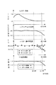
図2を参照して図6に示すように、A4サイズ普通紙の記録材Pで連続出力を行った。(a)はインダクタンスセンサ235aの出力から求めたトナー濃度の推移、(b)はパッチ検センサ24aのセンサ出力信号の推移である。(c)はトナー像の帯電量Q/Mの推移、(d)は記録材Pに転写・定着された最終画像の反射濃度の推移である。帯電量Q/Mは、転写前帯電装置25aの下流側で感光ドラム1上のトナー像を吸引し、吸引したトナーの電荷量Qとトナー重量Mをそれぞれ測定して求めた。反射濃度の測定には、X−Rite社の反射濃度計を使用し、感光ドラム1aにおけるトナー密度を0.6mg/cm2一定にして行った。
As shown in FIG. 6 with reference to FIG. 2, continuous output was performed with the recording material P of A4 size plain paper. (A) is the transition of the toner density obtained from the output of the
感光ドラム1aにおけるトナー密度を一定にして、一次転写及び二次転写を通じた転写効率の低下の影響を測定するためである。また、現像コントラストの調整によって感光ドラム1aに担持された制御用トナー像の濃度が一定に維持された際に、トナー像の帯電量Q/Mの低下による転写効率の低下がもたらす最終画像の画像濃度の低下量を測定するためである。 This is to measure the influence of a decrease in transfer efficiency through primary transfer and secondary transfer while keeping the toner density on the photosensitive drum 1a constant. In addition, when the density of the control toner image carried on the photosensitive drum 1a is maintained constant by adjusting the development contrast, the final image resulting in a decrease in transfer efficiency due to a decrease in the charge amount Q / M of the toner image. This is for measuring the amount of decrease in density.
図6の(a)に示すように、出力枚数が20万枚を超えた辺りから、トナー濃度(T/D比)の検知結果が、補正制御制限領域の下限値である5%に貼り付いた。トナー補充手段は、下限値である5%を下回らないように現像器にトナーの補充を行っている。 As shown in FIG. 6A, the detection result of the toner density (T / D ratio) is pasted to 5%, which is the lower limit value of the correction control restriction area, when the number of output sheets exceeds 200,000. It was. The toner replenishing means replenishes the developing device with toner so as not to fall below 5% which is the lower limit value.
図6の(b)に示すように、出力枚数が20万枚を超えた辺りから、パッチ検センサ24aのセンサ出力信号が500近傍から低下している。 As shown in FIG. 6 (b), the sensor output signal of the patch detection sensor 24a decreases from around 500 when the number of output sheets exceeds 200,000.
これは、図6の(c)に示すように、トナー帯電量Q/Mが低下して、所定の現像コントラストを用いて形成される制御用トナー像のパッチ濃度が高くなって制御用トナー像で散乱される反射光量が増加した結果、センサ出力信号が低下したことを示している。 This is because, as shown in FIG. 6C, the toner charge amount Q / M decreases, and the patch density of the control toner image formed using a predetermined development contrast increases, and the control toner image As a result, the sensor output signal has decreased as a result of the increase in the amount of reflected light scattered by.
出力枚数が20万枚を超えた以降は、補正制御制限領域となってトナーが強制的に補給制御されて、トナー帯電量Q/Mがますます低下する。しかし、現像コントラストを変化させることで少なくとも感光ドラム上に形成されるトナー像のトナー密度は一定に維持される。 After the number of output sheets exceeds 200,000, the toner is forcibly replenished under the correction control restriction area, and the toner charge amount Q / M further decreases. However, by changing the development contrast, at least the toner density of the toner image formed on the photosensitive drum is kept constant.
図6の(d)に示すように、しかし、トナー像の帯電量Q/Mが低下すると、一次転写部T1a及び二次転写部T2における転写効率が低下して、記録材Pに転写・定着される最終画像の反射濃度が低下する。 As shown in FIG. 6D, however, when the charge amount Q / M of the toner image decreases, the transfer efficiency in the primary transfer portion T1a and the secondary transfer portion T2 decreases, and transfer and fixing to the recording material P are performed. The reflection density of the final image is reduced.
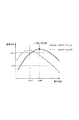
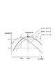
図2を参照して図7に示すように、感光ドラム1a上のトナー像の帯電量Q/Mが−25μC/g(実線)のときと−15μC/gのときとで、一次転写部T1aにおける適正な転写電流は違ってくる。図7は感光ドラム1a上のトナー密度が0.6mg/cm2の際の一次転写効率の転写電流依存性を示す。 As shown in FIG. 7 with reference to FIG. 2, the primary transfer portion T1a is obtained when the charge amount Q / M of the toner image on the photosensitive drum 1a is −25 μC / g (solid line) and −15 μC / g. The proper transfer current at is different. FIG. 7 shows the transfer current dependence of the primary transfer efficiency when the toner density on the photosensitive drum 1a is 0.6 mg / cm 2 .
帯電量Q/Mの低下により、転写効率の曲線が低電流側にシフトしているため、もともとの設定値では、転写電界が過剰に印加されて過剰な転写電流が流れて転写効率が低下する。同様な現象は、二次転写部T2においても発生している。そして、一次転写と二次転写との双方における転写効率の低下が積算されることで、最終画像の反射濃度の低下が発生している。 Since the transfer efficiency curve is shifted to the low current side due to the decrease in the charge amount Q / M, the transfer electric field is excessively applied and an excessive transfer current flows at the original set value, resulting in a decrease in transfer efficiency. . A similar phenomenon occurs in the secondary transfer portion T2. Then, the reduction in the transfer efficiency in both the primary transfer and the secondary transfer is integrated, resulting in a reduction in the reflection density of the final image.
また、出力枚数が27万枚を超えた辺りからは、感光ドラム1a及び中間転写ベルト81に対するトナーの静電付着力が低減することに加えて、過剰な転写電界印加されることから、トナーの飛び散りが増えて画像の粒状性が著しく悪化する。帯電量Q/Mが低下すると、このような画質劣化も深刻になる。
In addition, since the electrostatic adhesion force of the toner to the photosensitive drum 1a and the
実施例1では、パッチ検センサ24aで検知された制御用トナー像のパッチ濃度(センサ出力信号)と帯電量Q/Mの関係と、転写前帯電装置25aの設定電流値と帯電量Q/Mの関係とを予め記憶装置102に記録してある。
In the first embodiment, the relationship between the patch density (sensor output signal) of the control toner image detected by the patch detection sensor 24a and the charge amount Q / M, the set current value of the
制御部110は、これら2つの関係から、低下した帯電量Q/Mを補正するための転写前帯電装置25aの最適な設定電流値を求めて、画像形成時に使用する。所定のトナー像形成条件(現像コントラスト)で形成した制御用トナー像をパッチ検センサ24aで検知してパッチ濃度を求める。そして、通常値から変化した制御用トナー像の帯電量Q/Mを通常値に補正するために必要な転写前帯電装置25aの制御量(設定電流値)をパッチ濃度の検知結果から求める。これにより、制御用トナー像の帯電量Q/Mを直接測定することなく、精密に推定して通常値へ誘導できる。
Based on these two relationships, the
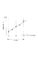
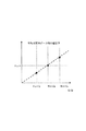
図8に示すように、一定のトナー像形成条件(現像コントラスト)で形成された制御用トナー像のパッチ濃度が高くなるとセンサ出力信号が下がって帯電量Q/Mは下げる傾向にあり、センサ出力信号と帯電量Q/Mとの関係には線形性がある。よって、直線の傾きAを予め記憶装置102に記録しておく。そして、新品状態の二成分現像剤での制御用トナー像でセンサ出力信号(基準値)と累積x枚出力時のセンサ出力信号(現在値)との差分値ΔD(x)から、帯電量Q/Mの変化ΔQ/M(x)は、傾きAを用いて式4により求められる。
ΔQ/M(x)=Ax(−ΔD(x)) ・・・(式4)
As shown in FIG. 8, when the patch density of the control toner image formed under a constant toner image forming condition (development contrast) increases, the sensor output signal tends to decrease and the charge amount Q / M tends to decrease, and the sensor output The relationship between the signal and the charge amount Q / M is linear. Therefore, the inclination A of the straight line is recorded in the
ΔQ / M (x) = Ax (−ΔD (x)) (Formula 4)
式4で(−ΔD(x))となっている理由は、ΔD(x)は、式2に示すように、初期値に対する差分であるため、ベクトル方向を変換する必要があるからである。 The reason that (−ΔD (x)) is given by Equation 4 is that ΔD (x) is a difference from the initial value as shown in Equation 2, and thus the vector direction needs to be converted.
図9に示すように、転写前帯電装置25aの設定電流値が上がると帯電性能が高まって、トナー像の帯電量Q/Mも上昇し、その関係には線形性がある。よって、直線の傾きBを予め記憶装置102に記録しておくことで、出力枚数xまでのトナー像の帯電量Q/Mの変化ΔQ/M(x)を相殺するための転写前帯電装置25aの設定電流値の変更値ΔIpostを求める。帯電量Q/Mの変化ΔQ/M(x)と設定電流値の変更値ΔIpost(x)との関係は式5により求められる。
ΔQ/M(x)=B×ΔIpost(x) ・・・(式5)
As shown in FIG. 9, as the set current value of the
ΔQ / M (x) = B × ΔIpost (x) (Formula 5)
式4と式5とにより、センサ出力信号の基準値とx枚出力時のセンサ出力信号との差分値ΔD(x)から転写前帯電装置25aの設定電流値の変更値ΔIpost(x)は式6により求められる。
ΔIpost(x)=(A/B)×(−ΔD(x)) ・・・(式6)
From the difference value ΔD (x) between the reference value of the sensor output signal and the sensor output signal when x sheets are output, the change value ΔIpost (x) of the set current value of the
ΔIpost (x) = (A / B) × (−ΔD (x)) (Expression 6)
式6により得られたΔIpost(x)が演算メモリ103に保持され、続く画像形成時には、制御部110から帯電器高圧回路32aを介して、転写前帯電装置25aにΔIpost(x)が設定される。これにより、トナー像の低下した帯電量Q/Mが正常値に補正される。すなわち、トナー像の帯電量Q/Mを直接に測定しなくても、パッチ濃度値の測定結果からトナー像の帯電量Q/Mを推定して、転写前帯電装置25aに適正な制御量を設定できる。
ΔIpost (x) obtained by Expression 6 is held in the
式6の関係を用いて、トナー濃度(T/D比)が5%に貼り付いた以降の転写前帯電装置25aの設定電流値を変更する制御を行わせた実験結果を図10に示す。図10中、(a)〜(d)の測定方法等は、図6を参照して説明したとおりである。
FIG. 10 shows an experimental result in which control is performed to change the set current value of the
図10の(c)に示すように、トナー像の帯電量Q/Mの推移において、黒丸が転写前帯電装置25aを使用しない場合、白抜き丸が式6の設定電流値で転写前帯電装置25aを作動させた場合である。実施例1の転写前帯電装置25aの設定電流値を変更する制御によって、トナー像の低下した帯電量Q/Mを初期値まで補正できている。
As shown in FIG. 10C, in the transition of the charge amount Q / M of the toner image, when the black circle does not use the
図10の(d)に示すように、最終画像の反射濃度の推移において、実線が転写前帯電装置25aを使用しない場合、破線が式6の設定電流値で転写前帯電装置25aを作動させた場合である。実施例1の転写前帯電装置25aの設定電流値を変更する制御によって、帯電量Q/Mの低下時に見られた出力画像の反射濃度の低下が見られず、良好な濃度推移を維持できている。
As shown in FIG. 10D, in the transition of the reflection density of the final image, when the solid line does not use the
さらに、転写前帯電装置25aを使用しない場合に見られた飛び散り画像も改善されており、画質の劣化も防止できた。
Further, the scattering image seen when the
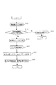
図2を参照して図11に示すように、制御部110は、インダクタンスセンサ235aの出力からトナー濃度(T/D比)を求める(S11)。
As shown in FIG. 11 with reference to FIG. 2, the
制御部110は、トナー濃度(T/D比)が5%〜12%の通常補給動作領域であれば(S12のNo)、転写前帯電装置25aの電流設定値を変更しない(S17)。しかし、トナー濃度(T/D比)が5%以下又は12%以上の強制補給領域(補正制御制限領域)であれば(S12のYes)、所定の現像コントラストで制御用トナー像を形成して(S13)、パッチ濃度を測定する(S14)。
The
制御部110は、パッチ濃度の測定結果を用いて、式6によって設定電流値の変更値ΔIpost(x)を演算して(S15)、転写前帯電装置25aに設定する(S16)。
The
実施例1の制御によれば、トナー補給の制限が行われている補給制御制限領域において、パッチ検ATR制御の検知結果を元に転写前帯電装置を制御する。これにより、感光ドラム上のトナー像の帯電量Q/Mの低下を補って、画像濃度と画質の安定化を図ることができる。 According to the control of the first embodiment, the pre-transfer charging device is controlled based on the detection result of the patch detection ATR control in the replenishment control restriction region where toner replenishment is restricted. As a result, it is possible to stabilize the image density and the image quality by compensating for the decrease in the charge amount Q / M of the toner image on the photosensitive drum.
<実施例2>
図12は転写電流と転写効率の関係の説明図である。図13は一次転写部におけるトナー像の帯電量と最大転写効率の転写電流値との関係の説明図、図14は二次転写部におけるトナー像の帯電量と最大転写効率の転写電流値との関係の説明図である。図15は実施例2の制御による効果の説明図、図16は実施例2の制御のフローチャートである。
<Example 2>
FIG. 12 is an explanatory diagram of the relationship between transfer current and transfer efficiency. FIG. 13 is an explanatory diagram of the relationship between the charge amount of the toner image in the primary transfer portion and the transfer current value of the maximum transfer efficiency, and FIG. 14 is the relationship between the charge amount of the toner image and the transfer current value of the maximum transfer efficiency in the secondary transfer portion. It is explanatory drawing of a relationship. FIG. 15 is an explanatory diagram of the effect by the control of the second embodiment, and FIG. 16 is a flowchart of the control of the second embodiment.
実施例1では、一次転写部T1aの転写電流の定電流値25μAに適合するように、転写前帯電装置25aを用いて、一次転写部T1aに搬送されるトナー像の帯電量Q/Mを調整した。これに対して、実施例2では、一次転写部T1aに搬送されるトナー像の帯電量Q/Mに適合するように、一次転写部T1aの転写電流の定電流設定値を調整する。
In Example 1, the charge amount Q / M of the toner image conveyed to the primary transfer portion T1a is adjusted by using the
図2を参照して図12に示すように、帯電量Q/Mが低下すると、転写効率の曲線が低電流側にシフトして最適な転写設定値が低電流側にシフトする。逆に、帯電量Q/Mが増加すると、転写効率の曲線が高電流側にシフトして最適な転写設定値が高電流側にシフトする。このような傾向は、トナー像を記録材へ転写する二次転写においても同様である。 As shown in FIG. 12 with reference to FIG. 2, when the charge amount Q / M decreases, the transfer efficiency curve shifts to the low current side, and the optimum transfer set value shifts to the low current side. Conversely, when the charge amount Q / M increases, the transfer efficiency curve shifts to the high current side and the optimum transfer set value shifts to the high current side. Such a tendency is the same in the secondary transfer in which the toner image is transferred to the recording material.
よって、帯電量Q/Mの変化に合わせて転写手段(一次転写部T1a/二次転写部T2)の電圧電流条件を補正できれば、トナー像の帯電量Q/Mが変動しても、転写効率の安定化が望める。 Therefore, if the voltage / current condition of the transfer means (primary transfer portion T1a / secondary transfer portion T2) can be corrected in accordance with the change in the charge amount Q / M, the transfer efficiency can be improved even if the charge amount Q / M of the toner image varies. Can be expected to stabilize.
実施例2では、インダクタンスセンサ235aの検知結果から補正制御制限領域(A、C:図5)にあると判断された場合に、一次転写部T1a及び二次転写部T2における転写電流の定電流の設定値が補正される。
In the second embodiment, when it is determined from the detection result of the
実施例2では、デフォルトでの一次転写電流設定値をI1=25μA、二次転写電流設定値をI2=45μAとして、予め記憶装置102に記録させておく。また、二成分現像剤が新品状態での帯電量Q/Mの値をQ/M(初期)=−25μC/gとして、予め記憶装置102に記録させておく。
In the second embodiment, the default primary transfer current setting value is set to I1 = 25 μA and the secondary transfer current setting value is set to I2 = 45 μA by default, and is recorded in the
図12に示すように、最適な転写電流値は、トナー像の帯電量Q/Mによって変化する。転写過程においては、トナー像の帯電電荷量に相当する電流を供給することが必要となるので、トナー像の帯電量Q/Mによって必要な転写電流値が変化する。 As shown in FIG. 12, the optimum transfer current value varies depending on the charge amount Q / M of the toner image. In the transfer process, it is necessary to supply a current corresponding to the charge amount of the toner image, so that the necessary transfer current value changes depending on the charge amount Q / M of the toner image.
図13に示すように、帯電量Q/Mと転写効率が最大になる転写電流値との関係には線形性があり、帯電量Q/Mの変化率と転写電流値の変化率が等しい。よって、トナー像の帯電量Q/Mの変化率から最適転写電流値の設定が可能である。補正制御制限領域(A、C:図5)にあって、トナー像の帯電量Q/Mが=−25μC/gでなくなった場合でも、そのトナー像の帯電量Q/Mに最適な一次転写電流設定値を設定できる。 As shown in FIG. 13, the relationship between the charge amount Q / M and the transfer current value at which the transfer efficiency is maximized is linear, and the change rate of the charge amount Q / M is equal to the change rate of the transfer current value. Therefore, the optimum transfer current value can be set from the change rate of the charge amount Q / M of the toner image. Even in the correction control limited region (A, C: FIG. 5), even when the charge amount Q / M of the toner image is no longer −25 μC / g, the primary transfer optimum for the charge amount Q / M of the toner image is achieved. The current setting value can be set.
図14に示すように、二次転写部T2においても、一次転写部T1aと同様に、帯電量Q/Mの変化率と転写電流値の変化率が等しく、帯電量Q/Mの変化率から最適転写電流値の設定が可能である。図14中、白抜き丸は、単色のトナー像での転写電流値、黒丸は単色のトナー像を重ねた二次色での転写電流値である。 As shown in FIG. 14, in the secondary transfer portion T2, similarly to the primary transfer portion T1a, the change rate of the charge amount Q / M and the change rate of the transfer current value are equal, and the change rate of the charge amount Q / M An optimum transfer current value can be set. In FIG. 14, a white circle is a transfer current value in a single color toner image, and a black circle is a transfer current value in a secondary color obtained by superimposing single color toner images.
図2に示すように、制御部110は、補正制御制限領域におけるパッチ濃度の変化を測定して、帯電量Q/Mの変化率を予測し、そこから最適転写電流値を計算して一次転写部T1a及び二次転写部T2に設定する。
As shown in FIG. 2, the
上述の式4より、新品状態の二成分現像剤で形成した制御用トナー像を濃度測定した際のセンサ出力信号とx枚出力時のセンサ出力信号との差分値ΔD(x)から、帯電量Q/Mの変化量ΔQ/M(x)が計算される。
ΔQ/M(x)=A×(−ΔD(x))
From the above equation 4, the charge amount is calculated from the difference value ΔD (x) between the sensor output signal when the density of the control toner image formed with the new two-component developer is measured and the sensor output signal when x sheets are output. A change amount Q / M (x) of Q / M is calculated.
ΔQ / M (x) = A × (−ΔD (x))
また、変化量ΔQ/Mと帯電量Q/M(初期)より、帯電量Q/Mの変化率の大きさは、式7により求められる。
(帯電量Q/Mの変化率)=(Q/M(初期)+ΔQ/M(x))/(Q/M(初期)) ・・・(式7)
Further, the magnitude of the rate of change of the charge amount Q / M can be obtained from Equation 7 based on the change amount ΔQ / M and the charge amount Q / M (initial).
(Change rate of charge amount Q / M) = (Q / M (initial) + ΔQ / M (x)) / (Q / M (initial)) (Expression 7)
式7と式4とから、x枚出力時の一次転写電流設定値I1(x)及び二次転写電流設定値I2(x)は、式8、式9により求められる。
I1(x)=(Q/M(初期)−AΔD(x))/(Q/M(初期))×I1 ・・・(式8)
I2(x)=(Q/M(初期)−AΔD(x))/(Q/M(初期))×I2 ・・・(式9)
From Expression 7 and Expression 4, the primary transfer current setting value I1 (x) and the secondary transfer current setting value I2 (x) when x sheets are output are obtained by Expression 8 and Expression 9.
I1 (x) = (Q / M (initial) −AΔD (x)) / (Q / M (initial)) × I1 (Equation 8)
I2 (x) = (Q / M (initial) −AΔD (x)) / (Q / M (initial)) × I2 (Equation 9)
式8、式9より得られたI1(x)、I2(x)を演算メモリ103に保持しておき、続く画像形成時には、制御部110から転写高圧回路33aにI1(x)が設定され、転写高圧回路41にI2(x)が設定される。
I1 (x) and I2 (x) obtained from Expressions 8 and 9 are held in the
式8、式9の関係を用いて、トナー濃度(T/D比)が5%以下の補正制御制限領域(C:図5)にある場合に転写電流設定値を変更する制御を行わせた実験結果を図15に示す。図15中、(a)〜(d)の測定方法等は、図6を参照して説明したとおりである。なお、図示を省略しているが、トナー濃度(T/D比)が補正制御制限領域(A:図5)にある場合についても、式8、式9の関係を用いて、同様に転写電流設定値を変更する制御が行われる。 Using the relationship of Expression 8 and Expression 9, control is performed to change the transfer current set value when the toner density (T / D ratio) is in the correction control restriction region (C: FIG. 5) of 5% or less. The experimental results are shown in FIG. In FIG. 15, the measurement methods and the like of (a) to (d) are as described with reference to FIG. 6. Although illustration is omitted, the transfer current is similarly applied using the relationship of Equations 8 and 9 even when the toner density (T / D ratio) is in the correction control limited region (A: FIG. 5). Control to change the set value is performed.
図15の(d)に示すように、最終画像の反射濃度の推移において、実線が転写電流値を変更しなかった場合、破線が式8、式9によって求めた転写電流設定値に変更した場合である。実施例2の転写電流設定値を変更する制御によって、帯電量Q/Mの低下時に見られた出力画像の反射濃度の低下が見られず、良好な濃度推移を維持できている。 As shown in FIG. 15D, in the transition of the reflection density of the final image, when the solid line does not change the transfer current value, the broken line changes to the transfer current set value obtained by Expression 8 and Expression 9. It is. With the control for changing the transfer current set value in the second embodiment, the decrease in the reflection density of the output image seen when the charge amount Q / M is decreased is not observed, and a good density transition can be maintained.
図2を参照して図16に示すように、制御部110は、インダクタンスセンサ235aの出力からトナー濃度(T/D比)を求める(S11)。
As shown in FIG. 16 with reference to FIG. 2, the
制御部110は、トナー濃度(T/D比)が5%〜12%の通常補給動作領域であれば(S12のNo)、一次転写電流設定値I1(x)及び二次転写電流設定値I2(x)を変更しない(S27)。しかし、トナー濃度(T/D比)が5%以下又は12%以上の補正制御制限領域であれば(S12のYes)、所定のトナー像形成条件(現像コントラスト)で制御用トナー像の帯電量Q/Mを推定するための制御用トナー像を形成する(S13)。そして、制御用トナー像をパッチ検センサ24aで検知して、パッチ濃度を測定する(S14)。
If the toner density (T / D ratio) is a normal replenishment operation region where the toner density (T / D ratio) is 5% to 12% (No in S12), the
制御部110は、通常値から変化した制御用トナー像の帯電量Q/Mを適正に転写させるための転写条件(転写電流値)の制御量をパッチ濃度の測定結果から求める。制御部110は、パッチ濃度の測定結果を用いて、式8、式9によって一次転写電流設定値I1(x)及び二次転写電流設定値I2(x)を演算する(S25)。そして、それぞれ一次転写部T1a及び二次転写部T2に設定する(S26)。これにより、トナー濃度(T/D比)が補正制御制限領域(A、C:図5)にあって、制御用トナー像の帯電量Q/Mが通常値から変化している場合に、制御用トナー像の帯電量Q/Mを直接測定することなく、適正な転写条件を設定できる。すなわち、定電流制御における定電流値を通じて適正なバイアスが設定される。
The
実施例2の制御によれば、トナー補給制御の制限が行われている補給制御制限領域において、パッチ検ATR制御の検知結果を元に一次転写部及び二次転写部の電流電圧条件を制御する。これにより、トナー像の帯電量Q/Mの低下に合わせた転写電流を確保して、画像濃度と画質の安定化を図ることができる。 According to the control of the second embodiment, the current voltage conditions of the primary transfer unit and the secondary transfer unit are controlled based on the detection result of the patch detection ATR control in the supply control limited region where the toner supply control is limited. . As a result, it is possible to secure a transfer current in accordance with a decrease in the charge amount Q / M of the toner image and to stabilize the image density and the image quality.
<実施例3>
図17は実施例3の制御による効果の説明図である。
<Example 3>
FIG. 17 is an explanatory diagram of the effect by the control of the third embodiment.
実施例1及び実施例2では、x枚出力時の補正制御制限領域におけるトナー像の帯電量Q/M(x)を、新品状態の二成分現像剤を用いた場合のトナー像の帯電量Q/M(初期)まで1度に補正した。つまり、制御用トナー像の濃度低下量を発見と同時に1回で相殺した。 In the first and second embodiments, the charge amount Q / M (x) of the toner image in the correction control restriction area when x sheets are output is set to the charge amount Q of the toner image when a two-component developer in a new state is used Correction was performed once up to / M (initial). In other words, the density reduction amount of the control toner image was canceled once at the same time as the discovery.
これに対して、実施例3では、x枚出力時の補正制御制限領域におけるトナー像の帯電量Q/M(x)を、新品状態の二成分現像剤を用いた場合のトナー像の帯電量Q/M(初期)に向かって少しずつ補正する。前回に比較した今回の制御用トナー像の濃度低下量が大きい場合に、制御用トナー像の濃度低下量を1回で100%相殺するような大きな制御量を用いないで、制御用トナー像の濃度低下量を数回に分けて徐々に相殺するような小さな制御量を用いる。 On the other hand, in Example 3, the charge amount Q / M (x) of the toner image in the correction control restriction area when x sheets are output is set as the charge amount of the toner image when the two-component developer in a new state is used. Correction is gradually made toward Q / M (initial). When the density reduction amount of the current control toner image compared to the previous time is large, without using a large control amount that cancels 100% of the density reduction amount of the control toner image at a time, the control toner image A small control amount that gradually cancels out the density reduction amount in several times is used.
実施例1及び実施例2では、パッチ濃度(センサ出力信号)が急激に変化した場合、転写前帯電装置25a又は一次転写部T1a、二次転写部T2の設定値を急激に変化させてしまう。このため、急激に設定値が変更になったところでは、濃度制御の安定性が崩れる可能性がある。
In the first and second embodiments, when the patch density (sensor output signal) changes abruptly, the setting values of the
そこで、実施例3では、1回に変更できる転写前帯電装置25aの設定電流値の変更値ΔIpost(x)に制限をかける。上述したように、パッチ濃度が変化してセンサ出力信号がΔD(x)変化した際に、パッチ濃度変化を相殺するために必要な設定電流値の変更値ΔIpost(x)は、式6によって計算される。なお、(A/B)は、上述したように、センサ出力信号を1変化させるために必要な設定電流値の変化量である。
ΔIpost(x)=(A/B)×(−ΔD(x)) ・・・(式6)
Therefore, in the third embodiment, the change value ΔIpost (x) of the set current value of the
ΔIpost (x) = (A / B) × (−ΔD (x)) (Expression 6)
具体的には、制御用トナー像の濃度低下に対応するセンサ出力信号の差分値ΔD(x)の大きさが閾値Z以上であった場合、1回の変更値ΔIpost(1回)で相殺するパッチ濃度(センサ出力信号の変化量ΔD(1回))を式10のように定める。
ΔD(1回)=Z(もしくはΔD(1回)=−Z) ・・・(式10)
ΔIpost(1回)=(A/B)×Z ・・・(式11)
Specifically, when the magnitude of the difference value ΔD (x) of the sensor output signal corresponding to the density reduction of the control toner image is equal to or greater than the threshold value Z, it is canceled by one change value ΔIpost (one time). The patch density (sensor output signal change amount ΔD (once)) is determined as shown in
ΔD (once) = Z (or ΔD (once) = − Z) (Equation 10)
ΔIpost (once) = (A / B) × Z (Expression 11)
実施例3では、Z=30としたが、他の値でも構わない。この場合、ΔDの値が一度に50変化しても、一度に補正できる濃度は、Z=30までであり、転写前帯電装置25aの設定電流値の変更値ΔIpost(x)に反映させなかった差分値20は次の画像形成時に持ち越される。
In the third embodiment, Z = 30, but other values may be used. In this case, even if the ΔD value changes by 50 at a time, the density that can be corrected at one time is up to Z = 30, and is not reflected in the change value ΔIpost (x) of the set current value of the
式10の関係を用いて、トナー濃度(T/D比)が補正制御制限領域にある場合に転写前帯電装置25aを作動させる制御を行わせた実験結果を図17に示す。図17中、(a)〜(d)の測定方法等は、図6を参照して説明したとおりである。
FIG. 17 shows a result of an experiment in which the
図17の(a)に示すように、トナー濃度(T/D比)が下限値5%に制御されている状態で、図17の(b)に示すように、所定のトナー像形成条件で形成されている制御用トナー像のパッチ濃度が急激に変化してセンサ出力信号が低下した。 As shown in FIG. 17A, the toner density (T / D ratio) is controlled to the lower limit value of 5%, and as shown in FIG. 17B, under predetermined toner image forming conditions. The patch density of the control toner image thus formed suddenly changed and the sensor output signal was lowered.
このとき、式10の補正量を用いて1回の濃度補正量を制限する実施例3の制御によって、転写前帯電装置25aが作動して、トナー像の低下した帯電量Q/Mは初期値まで緩やかに補正される。
At this time, the
図17の(d)に示すように、最終画像の反射濃度の推移において、実線が転写前帯電装置25aを使用しない場合、破線が式10の補正量で転写前帯電装置25aを作動させた場合である。実施例3の1回の濃度補正量を制限する制御によって、反射濃度も緩やかに回復する。
As shown in FIG. 17D, in the transition of the reflection density of the final image, the solid line indicates that the
実施例3の制御によれば、パッチ検ATR制御の結果を元に転写前帯電装置、一次転写部、二次転写部を制御する際に、パッチ検ATR制御の検知結果が急激に変化した際にも画像濃度の安定化を図ることができる。 According to the control of the third embodiment, when the pre-transfer charging device, the primary transfer unit, and the secondary transfer unit are controlled based on the result of the patch detection ATR control, the detection result of the patch detection ATR control changes suddenly. In addition, the image density can be stabilized.
1a、1b、1c、1d 像担持体(感光ドラム)
22a、22b、22c、22d、11a、11b、11c、11d 静電像形成手段(帯電ローラ、露光装置)
23a、23b、23c、23d 現像手段(現像装置)
24a、24b、24c、24d 濃度検知手段(パッチ検センサ)
25a、25b、25c、25d 転写前帯電装置
26a、26b、26c、26d、40 転写手段(一次転写ローラ、二次転写ローラ)
30a、30b、30c、30d、236a トナー補充手段(トナー補給槽、トナー搬送スクリュー)
33a、41 転写電源(転写高圧回路)
41 二次転写電源(転写高圧回路)
81 中間転写体(中間転写ベルト)
81、P 転写媒体(中間転写ベルト、記録材)
100 画像形成装置
110 制御手段(制御部)
235a、235b、235c、235d トナー検知手段(インダクタンスセンサ)
G 画像のトナー像
Q 制御用トナー像
P 記録材
T1a、T2 転写部(一次転写部、二次転写部)
1a, 1b, 1c, 1d Image carrier (photosensitive drum)
22a, 22b, 22c, 22d, 11a, 11b, 11c, 11d Electrostatic image forming means (charging roller, exposure device)
23a, 23b, 23c, 23d Developing means (developing device)
24a, 24b, 24c, 24d Density detection means (patch detection sensor)
25a, 25b, 25c, 25d Pre-transfer charging
30a, 30b, 30c, 30d, 236a Toner replenishing means (toner replenishing tank, toner conveying screw)
33a, 41 Transfer power supply (Transfer high voltage circuit)
41 Secondary transfer power supply (transfer high voltage circuit)
81 Intermediate transfer member (intermediate transfer belt)
81, P Transfer medium (intermediate transfer belt, recording material)
100
235a, 235b, 235c, 235d Toner detection means (inductance sensor)
G Image toner image Q Control toner image P Recording material T1a, T2 Transfer section (primary transfer section, secondary transfer section)
Claims (5)
前記トナー比率検知手段により検知されたトナー比率が所定の下限値に達すると、前記トナー補充手段は前記トナー比率が前記下限値を下回らないように前記現像手段にトナーを補充すると共に前記制御手段は前記濃度検知手段による検知結果に基づいて前記帯電手段に印加するバイアスの条件を調整することを特徴とする画像形成装置。 An image carrier, developing means for developing the electrostatic latent image formed on the image carrier using toner, toner replenishing means for replenishing toner to the developing means, and control unit formed by the developing means A density detecting means for detecting a toner image; a toner ratio detecting means for detecting a toner ratio in a two-component developer in the developing means; a charging means for charging the toner carried on the image carrier; A control unit that controls a bias applied to the charging unit;
When the toner ratio detected by the toner ratio detecting means reaches a predetermined lower limit value, the toner replenishing means replenishes the developing means with toner so that the toner ratio does not fall below the lower limit value, and the control means An image forming apparatus, wherein a bias condition applied to the charging unit is adjusted based on a detection result by the density detection unit.
前記制御手段は、前記トナー比率が前記所定の下限値に維持されるように前記トナー補充手段を制御するとともに、所定のトナー像形成条件で形成した制御用トナー像の濃度低下量に応じた制御量で前記帯電手段を制御することを特徴とする請求項1記載の画像形成装置。 The charging means is a pre-transfer charging device that changes the amount of charge by irradiating a toner image carried on the image carrier with charged particles.
The control means controls the toner replenishing means so that the toner ratio is maintained at the predetermined lower limit value, and controls according to the density reduction amount of the control toner image formed under the predetermined toner image forming conditions. The image forming apparatus according to claim 1, wherein the charging unit is controlled by an amount.
前記制御手段は、前記制御用トナー像の濃度低下量を相殺するよりも小さな制御量で、前記帯電手段を制御することを特徴とする請求項2記載の画像形成装置。 The control toner image is formed at a predetermined intermediate density gradation in the interval of the toner image of the image,
The image forming apparatus according to claim 2, wherein the control unit controls the charging unit with a control amount smaller than the amount of decrease in density of the control toner image.
前記トナー比率検知手段により検知されたトナー比率が所定の下限値に達すると、前記トナー補充手段は前記トナー比率が前記下限値を下回らないように前記現像手段にトナーを補充すると共に前記制御手段は前記濃度検知手段による検知結果に基づいて前記転写手段に印加するバイアスの条件を調整することを特徴とする画像形成装置。 An image carrier, developing means for developing the electrostatic latent image formed on the image carrier using toner, toner replenishing means for replenishing toner to the developing means, and control unit formed by the developing means A density detecting means for detecting a toner image; a toner ratio detecting means for detecting a toner ratio in a two-component developer in the developing means; and a transfer member for transferring the toner carried on the image carrier to a transfer material. And an image forming apparatus having a control unit that controls a bias applied to the transfer unit.
When the toner ratio detected by the toner ratio detecting means reaches a predetermined lower limit value, the toner replenishing means replenishes the developing means with toner so that the toner ratio does not fall below the lower limit value, and the control means An image forming apparatus, wherein a bias condition applied to the transfer unit is adjusted based on a detection result by the density detection unit.
Priority Applications (2)
| Application Number | Priority Date | Filing Date | Title |
|---|---|---|---|
| JP2008229547A JP5388513B2 (en) | 2008-09-08 | 2008-09-08 | Image forming apparatus |
| US12/554,110 US8200109B2 (en) | 2008-09-08 | 2009-09-04 | Image forming apparatus |
Applications Claiming Priority (1)
| Application Number | Priority Date | Filing Date | Title |
|---|---|---|---|
| JP2008229547A JP5388513B2 (en) | 2008-09-08 | 2008-09-08 | Image forming apparatus |
Publications (2)
| Publication Number | Publication Date |
|---|---|
| JP2010061079A true JP2010061079A (en) | 2010-03-18 |
| JP5388513B2 JP5388513B2 (en) | 2014-01-15 |
Family
ID=41799413
Family Applications (1)
| Application Number | Title | Priority Date | Filing Date |
|---|---|---|---|
| JP2008229547A Active JP5388513B2 (en) | 2008-09-08 | 2008-09-08 | Image forming apparatus |
Country Status (2)
| Country | Link |
|---|---|
| US (1) | US8200109B2 (en) |
| JP (1) | JP5388513B2 (en) |
Cited By (11)
| Publication number | Priority date | Publication date | Assignee | Title |
|---|---|---|---|---|
| JP2011232545A (en) * | 2010-04-27 | 2011-11-17 | Canon Inc | Image forming apparatus, and control method thereof |
| JP2013125100A (en) * | 2011-12-13 | 2013-06-24 | Canon Inc | Image forming apparatus |
| JP2015055780A (en) * | 2013-09-12 | 2015-03-23 | コニカミノルタ株式会社 | Wet type image forming apparatus |
| JP2017058655A (en) * | 2015-09-17 | 2017-03-23 | 富士ゼロックス株式会社 | Image forming apparatus and program |
| JP2018010143A (en) * | 2016-07-13 | 2018-01-18 | キヤノン株式会社 | Image forming apparatus |
| JP2018116158A (en) * | 2017-01-18 | 2018-07-26 | キヤノン株式会社 | Image-forming device |
| JP2020118942A (en) * | 2019-01-28 | 2020-08-06 | 京セラドキュメントソリューションズ株式会社 | Image forming apparatus |
| JP2020118943A (en) * | 2019-01-28 | 2020-08-06 | 京セラドキュメントソリューションズ株式会社 | Image forming apparatus |
| JP2020118941A (en) * | 2019-01-28 | 2020-08-06 | 京セラドキュメントソリューションズ株式会社 | Image forming apparatus |
| JP2020148945A (en) * | 2019-03-14 | 2020-09-17 | 富士ゼロックス株式会社 | Image formation device |
| JP2020154059A (en) * | 2019-03-19 | 2020-09-24 | 富士ゼロックス株式会社 | Image formation apparatus |
Families Citing this family (7)
| Publication number | Priority date | Publication date | Assignee | Title |
|---|---|---|---|---|
| JP5767463B2 (en) | 2010-12-15 | 2015-08-19 | キヤノン株式会社 | Image forming apparatus |
| JP5875228B2 (en) * | 2011-01-19 | 2016-03-02 | キヤノン株式会社 | Image forming apparatus |
| JP2013156509A (en) * | 2012-01-31 | 2013-08-15 | Canon Inc | Printer, control method of printer, and program |
| JP6274387B2 (en) * | 2012-03-07 | 2018-02-07 | キヤノン株式会社 | Image forming apparatus |
| JP5645862B2 (en) * | 2012-03-14 | 2014-12-24 | 京セラドキュメントソリューションズ株式会社 | Image forming apparatus |
| JP6128871B2 (en) * | 2013-02-05 | 2017-05-17 | キヤノン株式会社 | Image forming apparatus |
| JP7379967B2 (en) * | 2019-09-10 | 2023-11-15 | 富士フイルムビジネスイノベーション株式会社 | Image forming device |
Citations (4)
| Publication number | Priority date | Publication date | Assignee | Title |
|---|---|---|---|---|
| JPH11338250A (en) * | 1998-05-26 | 1999-12-10 | Minolta Co Ltd | Electrophotographic device |
| JP2004226798A (en) * | 2003-01-24 | 2004-08-12 | Konica Minolta Holdings Inc | Image forming apparatus |
| JP2005017770A (en) * | 2003-06-26 | 2005-01-20 | Ricoh Co Ltd | Image forming apparatus |
| JP2007078896A (en) * | 2005-09-12 | 2007-03-29 | Canon Inc | Image forming apparatus |
Family Cites Families (4)
| Publication number | Priority date | Publication date | Assignee | Title |
|---|---|---|---|---|
| US5179397A (en) | 1989-04-03 | 1993-01-12 | Canon Kabushiki Kaisha | Image forming apparatus with constant voltage and constant current control |
| JP2614309B2 (en) | 1989-04-03 | 1997-05-28 | キヤノン株式会社 | Image forming device |
| US5253022A (en) | 1989-05-18 | 1993-10-12 | Canon Kabushiki Kaisha | Image forming apparatus |
| KR960001957B1 (en) * | 1991-07-06 | 1996-02-08 | 후지쓰 가부시끼가이샤 | Conductive roller type toner image transferring apparatus |
-
2008
- 2008-09-08 JP JP2008229547A patent/JP5388513B2/en active Active
-
2009
- 2009-09-04 US US12/554,110 patent/US8200109B2/en active Active
Patent Citations (4)
| Publication number | Priority date | Publication date | Assignee | Title |
|---|---|---|---|---|
| JPH11338250A (en) * | 1998-05-26 | 1999-12-10 | Minolta Co Ltd | Electrophotographic device |
| JP2004226798A (en) * | 2003-01-24 | 2004-08-12 | Konica Minolta Holdings Inc | Image forming apparatus |
| JP2005017770A (en) * | 2003-06-26 | 2005-01-20 | Ricoh Co Ltd | Image forming apparatus |
| JP2007078896A (en) * | 2005-09-12 | 2007-03-29 | Canon Inc | Image forming apparatus |
Cited By (17)
| Publication number | Priority date | Publication date | Assignee | Title |
|---|---|---|---|---|
| JP2011232545A (en) * | 2010-04-27 | 2011-11-17 | Canon Inc | Image forming apparatus, and control method thereof |
| JP2013125100A (en) * | 2011-12-13 | 2013-06-24 | Canon Inc | Image forming apparatus |
| JP2015055780A (en) * | 2013-09-12 | 2015-03-23 | コニカミノルタ株式会社 | Wet type image forming apparatus |
| US9383705B2 (en) | 2013-09-12 | 2016-07-05 | Konica Minolta, Inc. | Wet-type image formation apparatus adjusting toner conveyance amount and toner charge amount |
| JP2017058655A (en) * | 2015-09-17 | 2017-03-23 | 富士ゼロックス株式会社 | Image forming apparatus and program |
| JP2018010143A (en) * | 2016-07-13 | 2018-01-18 | キヤノン株式会社 | Image forming apparatus |
| JP2018116158A (en) * | 2017-01-18 | 2018-07-26 | キヤノン株式会社 | Image-forming device |
| JP2020118943A (en) * | 2019-01-28 | 2020-08-06 | 京セラドキュメントソリューションズ株式会社 | Image forming apparatus |
| JP2020118942A (en) * | 2019-01-28 | 2020-08-06 | 京セラドキュメントソリューションズ株式会社 | Image forming apparatus |
| JP2020118941A (en) * | 2019-01-28 | 2020-08-06 | 京セラドキュメントソリューションズ株式会社 | Image forming apparatus |
| JP7177984B2 (en) | 2019-01-28 | 2022-11-25 | 京セラドキュメントソリューションズ株式会社 | image forming device |
| JP7216891B2 (en) | 2019-01-28 | 2023-02-02 | 京セラドキュメントソリューションズ株式会社 | image forming device |
| JP7216890B2 (en) | 2019-01-28 | 2023-02-02 | 京セラドキュメントソリューションズ株式会社 | image forming device |
| JP2020148945A (en) * | 2019-03-14 | 2020-09-17 | 富士ゼロックス株式会社 | Image formation device |
| JP7225963B2 (en) | 2019-03-14 | 2023-02-21 | 富士フイルムビジネスイノベーション株式会社 | image forming device |
| JP2020154059A (en) * | 2019-03-19 | 2020-09-24 | 富士ゼロックス株式会社 | Image formation apparatus |
| JP7225974B2 (en) | 2019-03-19 | 2023-02-21 | 富士フイルムビジネスイノベーション株式会社 | image forming device |
Also Published As
| Publication number | Publication date |
|---|---|
| JP5388513B2 (en) | 2014-01-15 |
| US20100061750A1 (en) | 2010-03-11 |
| US8200109B2 (en) | 2012-06-12 |
Similar Documents
| Publication | Publication Date | Title |
|---|---|---|
| JP5388513B2 (en) | Image forming apparatus | |
| US8861994B2 (en) | Image forming apparatus and toner supply control method | |
| US8805221B2 (en) | Image forming apparatus | |
| JP2021033020A (en) | Image forming apparatus | |
| JP4826172B2 (en) | Developing device and image forming apparatus using the same | |
| US9042753B2 (en) | Image forming apparatus | |
| JP2007078942A (en) | Image forming apparatus | |
| JP2010085848A (en) | Image forming apparatus | |
| JP2010091804A (en) | Development method and device for image forming apparatus | |
| JP2016206599A (en) | Image forming apparatus | |
| JP4363035B2 (en) | Image forming apparatus | |
| JP5023504B2 (en) | Developing device and image forming apparatus using the same | |
| JP2006064955A (en) | Image forming apparatus | |
| JP5982784B2 (en) | Image forming apparatus | |
| JP7476603B2 (en) | Image forming device | |
| JP4631325B2 (en) | Image density adjusting apparatus and image forming apparatus using the same | |
| US11526107B2 (en) | Image forming apparatus | |
| JP2018081206A (en) | Image forming apparatus | |
| JP6597581B2 (en) | Image forming apparatus and operation amount correction method | |
| JP6662734B2 (en) | Image forming apparatus, control program, and control method | |
| JP5982785B2 (en) | Image forming apparatus | |
| JP2006091324A (en) | Image forming apparatus | |
| JP5998893B2 (en) | Image forming apparatus and developing condition correction method | |
| JP2022046157A (en) | Image formation apparatus | |
| JP2022076086A (en) | Image forming apparatus |
Legal Events
| Date | Code | Title | Description |
|---|---|---|---|
| A621 | Written request for application examination |
Free format text: JAPANESE INTERMEDIATE CODE: A621 Effective date: 20110907 |
|
| RD05 | Notification of revocation of power of attorney |
Free format text: JAPANESE INTERMEDIATE CODE: A7425 Effective date: 20120125 |
|
| RD03 | Notification of appointment of power of attorney |
Free format text: JAPANESE INTERMEDIATE CODE: A7423 Effective date: 20120203 |
|
| A977 | Report on retrieval |
Free format text: JAPANESE INTERMEDIATE CODE: A971007 Effective date: 20121129 |
|
| A131 | Notification of reasons for refusal |
Free format text: JAPANESE INTERMEDIATE CODE: A131 Effective date: 20130205 |
|
| RD04 | Notification of resignation of power of attorney |
Free format text: JAPANESE INTERMEDIATE CODE: A7424 Effective date: 20130228 |
|
| A521 | Request for written amendment filed |
Free format text: JAPANESE INTERMEDIATE CODE: A523 Effective date: 20130405 |
|
| TRDD | Decision of grant or rejection written | ||
| A01 | Written decision to grant a patent or to grant a registration (utility model) |
Free format text: JAPANESE INTERMEDIATE CODE: A01 Effective date: 20130910 |
|
| A61 | First payment of annual fees (during grant procedure) |
Free format text: JAPANESE INTERMEDIATE CODE: A61 Effective date: 20131008 |
|
| R151 | Written notification of patent or utility model registration |
Ref document number: 5388513 Country of ref document: JP Free format text: JAPANESE INTERMEDIATE CODE: R151 |