JP5767463B2 - Image forming apparatus - Google Patents
Image forming apparatus Download PDFInfo
- Publication number
- JP5767463B2 JP5767463B2 JP2010279857A JP2010279857A JP5767463B2 JP 5767463 B2 JP5767463 B2 JP 5767463B2 JP 2010279857 A JP2010279857 A JP 2010279857A JP 2010279857 A JP2010279857 A JP 2010279857A JP 5767463 B2 JP5767463 B2 JP 5767463B2
- Authority
- JP
- Japan
- Prior art keywords
- image
- developer
- density
- toner
- developing
- Prior art date
- Legal status (The legal status is an assumption and is not a legal conclusion. Google has not performed a legal analysis and makes no representation as to the accuracy of the status listed.)
- Expired - Fee Related
Links
Images


Classifications
-
- G—PHYSICS
- G03—PHOTOGRAPHY; CINEMATOGRAPHY; ANALOGOUS TECHNIQUES USING WAVES OTHER THAN OPTICAL WAVES; ELECTROGRAPHY; HOLOGRAPHY
- G03G—ELECTROGRAPHY; ELECTROPHOTOGRAPHY; MAGNETOGRAPHY
- G03G15/00—Apparatus for electrographic processes using a charge pattern
- G03G15/06—Apparatus for electrographic processes using a charge pattern for developing
- G03G15/08—Apparatus for electrographic processes using a charge pattern for developing using a solid developer, e.g. powder developer
- G03G15/0822—Arrangements for preparing, mixing, supplying or dispensing developer
- G03G15/0848—Arrangements for testing or measuring developer properties or quality, e.g. charge, size, flowability
- G03G15/0849—Detection or control means for the developer concentration
-
- G—PHYSICS
- G03—PHOTOGRAPHY; CINEMATOGRAPHY; ANALOGOUS TECHNIQUES USING WAVES OTHER THAN OPTICAL WAVES; ELECTROGRAPHY; HOLOGRAPHY
- G03G—ELECTROGRAPHY; ELECTROPHOTOGRAPHY; MAGNETOGRAPHY
- G03G15/00—Apparatus for electrographic processes using a charge pattern
- G03G15/50—Machine control of apparatus for electrographic processes using a charge pattern, e.g. regulating differents parts of the machine, multimode copiers, microprocessor control
- G03G15/5033—Machine control of apparatus for electrographic processes using a charge pattern, e.g. regulating differents parts of the machine, multimode copiers, microprocessor control by measuring the photoconductor characteristics, e.g. temperature, or the characteristics of an image on the photoconductor
- G03G15/5041—Detecting a toner image, e.g. density, toner coverage, using a test patch
Description
本発明は、電子写真方式或いは静電記録方式を利用した、複写機、プリンタ等の画像形成装置に関するものである。 The present invention relates to an image forming apparatus such as a copying machine or a printer using an electrophotographic system or an electrostatic recording system.
画像形成装置において、感光体を帯電し、レーザ光による像露光を行い、これを現像する、いわゆる電子写真方式のレーザプリンタが知られている。このようなレーザプリンタは画像品質が高く、高速である等の長所を持っており、例えば複写機等の出力装置や通常のプリンタとして一般に広く用いられている。このような画像形成装置が具備する現像器には、磁性トナーを主成分とした一成分現像剤、又は非磁性トナーと磁性キャリアとを主成分とした二成分現像剤が用いられている。特に、フルカラーやマルチカラー画像を形成する画像形成装置では、画像の色味などの観点から、ほとんどの現像器が二成分現像剤を使用している。 In an image forming apparatus, a so-called electrophotographic laser printer is known in which a photosensitive member is charged, image exposure is performed with laser light, and development is performed. Such a laser printer has advantages such as high image quality and high speed, and is widely used as an output device such as a copying machine or a normal printer. A developing device provided in such an image forming apparatus uses a one-component developer containing magnetic toner as a main component or a two-component developer containing non-magnetic toner and a magnetic carrier as main components. In particular, in an image forming apparatus that forms a full-color or multi-color image, most developing devices use a two-component developer from the viewpoint of the color of the image.
近年、このような画像形成装置がPOD(Print On Demand)と呼ばれる軽印刷市場で用いられるようになってきており、それに対応するべくさらなる高画質、高安定化の要求が高まっている。高安定化において重要視される項目の一つとして、濃度階調特性の安定化がある。画像形成装置は特に環境変動、耐久変動等に対して出力濃度変化の感度が高いため、画像の濃度階調を常に適正な状態に保つ必要がある。 In recent years, such image forming apparatuses have come to be used in the light printing market called POD (Print On Demand), and there is an increasing demand for higher image quality and higher stability. One of the items regarded as important in high stabilization is stabilization of density gradation characteristics. Since the image forming apparatus is particularly sensitive to changes in output density with respect to environmental fluctuations, durability fluctuations, etc., it is necessary to always maintain the density gradation of the image in an appropriate state.
濃度階調安定性の手法として、特許文献1にある自動階調補正というものがある。これは、記録材上に階調パターン画像を形成し、この画像の光学濃度を読み取ることで所望の階調特性が得られるようにγLUT(Look up table)を作成し、階調制御を行っているものもある。自動階調補正を行うことで、環境変動、耐久変動等によらず安定したな濃度階調特性を得ることができる。
As a technique of density gradation stability, there is an automatic gradation correction disclosed in
濃度階調安定性のもう一つの手法として、特許文献2にあるパッチ検知ATR(Auto Toner Replenisher)制御と呼ばれるトナーの帯電特性を安定化させる手法がある。この手法は、二成分現像剤を用いた際のトナーの帯電特性を安定化させる手法である。電子写真感光体(感光体)上に参照用の画像濃度検知用画像パターン(パッチ画像)を作像し、画像濃度センサにより当該パッチ画像を検知し、その検知値が所望の値になるように、トナーの補給量を制御することでトナーの帯電特性を安定化させている。
As another method of density gradation stability, there is a method of stabilizing toner charging characteristics called patch detection ATR (Auto Toner Replenisher) control described in
しかしながら、自動階調補正の課題として、自動階調補正後にトナー帯電特性等の現像剤の状態が変化すると最適な濃度階調特性を維持できなくなることがある。例えば、環境変動、現像剤放置時間などの要因で、トナー帯電特性が所望でない時に自動階調補正を行う場合、自動階調補正後に、パッチ検知ATR制御などによってトナー帯電特性が所望の値に戻ると、濃度階調特性が大きくずれてしまうことがある。 However, as a problem of automatic gradation correction, when the developer state such as toner charging characteristics changes after automatic gradation correction, the optimum density gradation characteristics may not be maintained. For example, when automatic gradation correction is performed when the toner charging characteristic is not desired due to factors such as environmental fluctuation and developer leaving time, the toner charging characteristic returns to a desired value by patch detection ATR control after automatic gradation correction. In this case, the density gradation characteristics may be greatly shifted.
この課題への対策として、特許文献1において、自動階調補正後については、像担持体上のパッチ画像の濃度を用いて濃度階調特性を変更し、濃度階調特性の安定化を図る手法が提案されている。しかし、この手法では、像担持体上のパッチ画像は転写、定着工程を経ていない濃度であるために、記録材上に形成した画像の濃度を用いる自動階調補正と比べると、精度面では劣ってしまうことがあり、近年の高安定化の要求を十分に満たすことができない。また、この手法における効果をより上げるためには、多階調のパッチ画像を形成する必要があるため、画像形成中におけるのダウンタイムが大きく、トナー使用量も増加するために、所望の費用対効果を得ることができない。
As a countermeasure to this problem, in
また、自動階調補正後のトナー帯電特性を維持するようにパッチ検知ATR制御の目標値を変更すれば、階調特性の維持は可能と考えられる。しかし、この状態では、トナー帯電量が低いなどの現像剤の状態が所望でないことによる不具合が発生することがある。具体的には、画質劣化(粒状性低下(がさつき感)/白地かぶり/転写不良による白抜け等)、トナー飛散などが起こることが想定される。 In addition, if the target value of the patch detection ATR control is changed so as to maintain the toner charging characteristic after the automatic gradation correction, the gradation characteristic can be maintained. However, in this state, a problem may occur due to an undesired developer state such as a low toner charge amount. More specifically, it is assumed that image quality deterioration (decrease in graininess (feeling of roughness) / white background fog / white spots due to transfer failure, etc.), toner scattering, and the like occur.
本発明は、上述の問題に鑑みて成されたものであり、自動階調補正後のトナー帯電特性を維持するとともに、自動階調補正を行う際の不必要なダウンタイムや無駄なトナーの消費を低減する画像形成装置を提供することを目的とする。 The present invention has been made in view of the above-described problems, and maintains the toner charging characteristics after automatic gradation correction, and unnecessary downtime and unnecessary toner consumption when performing automatic gradation correction. An object of the present invention is to provide an image forming apparatus that reduces the above-described problem.
上記課題を解決するため、請求項1に記載の画像形成装置は、像担持体と、前記像担持体に露光することにより静電潜像を形成する露光手段と、現像剤としてトナー及び磁性キャリアを含み、前記像担持体に形成された静電潜像を現像剤像に現像する現像手段とを備え、記録材に形成した階調パターンを読み取って、濃度階調特性を調整する自動階調補正処理を実行する画像形成装置であって、前記自動階調補正処理を実行する前に、前記露光手段及び前記現像手段を用いて前記像担持体に基準現像剤像を形成させる形成手段と、前記像担持体に形成された前記基準現像剤像の濃度を検知する濃度検知手段と、前記現像手段が有する前記現像剤の帯電量が所定の範囲内であることを前記濃度検知手段の検知結果が示す場合に、前記自動階調補正処理を実行させ、前記現像手段が有する前記現像剤の帯電量が所定の範囲内でないと前記濃度検知手段の検知結果が示す場合に、前記現像手段が有する前記現像剤の帯電量を所定の範囲内にするための調整処理を実行した後に前記自動階調補正処理を実行させる制御手段とを備え、前記制御手段は、前記濃度検知手段によって検知された前記基準現像剤像の濃度値と、前記画像形成装置の記憶手段に予め記憶されている基準値との差分が所定の閾値を超える場合であって、かつ、該濃度値が該基準値以下である場合であって、かつ、前回形成した基準現像剤像の濃度値と比較して今回形成した基準現像剤像の濃度値が所定の閾値を超えて低下していない場合に、前記調整処理として、前記像担持体へトナーを吐き出す吐き出し動作を実行することを特徴とする。また、他の請求項に記載の画像形成装置は、像担持体と、前記像担持体に露光することにより静電潜像を形成する露光手段と、現像剤としてトナー及び磁性キャリアを含み、前記像担持体に形成された静電潜像を現像剤像に現像する現像手段とを備え、記録材に形成した階調パターンを読み取って、濃度階調特性を調整する自動階調補正処理を実行する画像形成装置であって、前記自動階調補正処理を実行する前に、前記露光手段及び前記現像手段を用いて前記像担持体に基準現像剤像を形成させる形成手段と、前記像担持体に形成された前記基準現像剤像の濃度を検知する濃度検知手段と、前記現像手段が有する前記現像剤の帯電量が所定の範囲内であることを前記濃度検知手段の検知結果が示す場合に、前記自動階調補正処理を実行させ、前記現像手段が有する前記現像剤の帯電量が所定の範囲内でないと前記濃度検知手段の検知結果が示す場合に、前記現像手段が有する前記現像剤の帯電量を所定の範囲内にするための調整処理を実行した後に前記自動階調補正処理を実行させる制御手段とを備え、前記制御手段は、前記濃度検知手段によって検知された前記基準現像剤像の濃度値と、前記画像形成装置の記憶手段に予め記憶されている基準値との差分が所定の閾値を超える場合であって、かつ、該濃度値が該基準値以下である場合であって、かつ、前回形成した基準現像剤像の濃度値と比較して今回形成した基準現像剤像の濃度値が所定の閾値を超えて低下している場合に、前記調整処理として、前記現像手段に含まれるトナー及び磁性キャリアを撹拌するための空回転動作を実行することを特徴とする。また、他の請求項に記載の画像形成装置は、像担持体と、前記像担持体に露光することにより静電潜像を形成する露光手段と、現像剤としてトナー及び磁性キャリアを含み、前記像担持体に形成された静電潜像を現像剤像に現像する現像手段とを備え、記録材に形成した階調パターンを読み取って、濃度階調特性を調整する自動階調補正処理を実行する画像形成装置であって、前記自動階調補正処理を実行する前に、前記露光手段及び前記現像手段を用いて前記像担持体に基準現像剤像を形成させる形成手段と、前記像担持体に形成された前記基準現像剤像の濃度を検知する濃度検知手段と、前記現像手段が有する前記現像剤の帯電量が所定の範囲内であることを前記濃度検知手段の検知結果が示す場合に、前記自動階調補正処理を実行させ、前記現像手段が有する前記現像剤の帯電量が所定の範囲内でないと前記濃度検知手段の検知結果が示す場合に、前記現像手段が有する前記現像剤の帯電量を所定の範囲内にするための調整処理を実行した後に前記自動階調補正処理を実行させる制御手段とを備え、前記制御手段は、直前に画像形成されてからの水分の変化量、直前に画像形成されてからの経過時間、該経過時間内に前記現像手段が動作した時間、過去の画像形成における画像形成領域の割合を示す平均画像デューティー、及び、画像形成枚数の少なくとも1つの情報を用いて、前記現像手段が有する前記現像剤の帯電量が所定の範囲内であるか否かに関わらず、前記調整処理を実行することなく前記自動階調補正処理を実行させることを決定する決定手段を備えることを特徴とする。In order to solve the above problems, an image forming apparatus according to
本発明は、自動階調補正後のトナー帯電特性を維持するとともに、自動階調補正を行う際の不必要なダウンタイムや無駄なトナーの消費を低減する画像形成装置を提供できる。 The present invention can provide an image forming apparatus that maintains toner charging characteristics after automatic gradation correction and reduces unnecessary downtime and unnecessary toner consumption when performing automatic gradation correction.
以下、本発明を実施するための形態について図面を用いて説明する。尚、以下の実施形態は特許請求の範囲に係る発明を限定するものでなく、また実施形態で説明されている特徴の組み合わせの全てが発明の解決手段に必須のものとは限らない。 Hereinafter, embodiments for carrying out the present invention will be described with reference to the drawings. The following embodiments do not limit the invention according to the claims, and all combinations of features described in the embodiments are not necessarily essential to the solution means of the invention.
<画像形成装置の構成>
以下では、図2を参照して、本発明に係る画像形成装置の構成例について説明する。本発明に適用される画像形成装置は、電子写真方式の画像形成装置である。画像形成装置本体内には矢印X方向に走行する無端状の中間転写ベルト(ITB)81が配設されている。この中間転写ベルト81は駆動ローラ37、テンションローラ38、及び2次転写内ローラ39の3つのローラによって張架されている。本実施例での張架力は3kgfであるが、他の張架力でもかまわない。中間転写ベルト81は、ポリカーボネート、ポリエチレンテレフタレート樹脂フィルム、ポリフッ化ビニリデン樹脂フィルム、ポリイミド、エチレン4フッ化エチレン共重合体等のような誘電体樹脂等に帯電防止剤としてカーボンブラックを適当量含有させ、その体積抵抗率を1E+8〜1E+13[Ω・cm]に調整させているが他の材質、体積抵抗率でもよい。本実施例では、厚さ80um、体積抵抗率を1E+10[Ω・cm]の導電性ポリイミドのシームレスベルトを使用した。また、本実施例での中間転写ベルトの走行速度は300mm/sとしたが、他の速度でもよい。
<Configuration of image forming apparatus>
Hereinafter, a configuration example of the image forming apparatus according to the present invention will be described with reference to FIG. The image forming apparatus applied to the present invention is an electrophotographic image forming apparatus. An endless intermediate transfer belt (ITB) 81 that runs in the direction of arrow X is disposed in the image forming apparatus main body. The
給紙カセット60から取り出された記録材Pは、ピックアップローラを経て搬送ローラ41に供給され、さらに同図左方に搬送される。
The recording material P taken out from the
中間転写ベルト81の上方には、ほぼ同様の構成をもつ4個の画像形成部Pa、Pb、Pc、Pdが直列状に配置されている。画像形成部Paを例にとって画像形成部を説明する。画像形成部Paの詳細な構成を図1に示す。画像形成部は、像担持体として、回転可能に配置されたドラム状の電子写真感光体(以下「感光ドラム」と称する。)1aを備えている。その中心には支軸(不図示)を有し、この支軸を中心として矢印R1方向に、不図示の駆動手段によって回転駆動されるようになっている。本実施例では、感光ドラム1aの表面速度は300mm/sであるが、他の速度でもよい。感光ドラム1aの周囲には、1次帯電器11a、スキャナ部(露光装置)12a、表面電位センサ26a、現像器2a、パッチ検知ATR(Auto Toner Replenisher)センサ26a、1次転写ローラ14a、クリーニング器15a等のプロセス機器が配置されている。
Above the
1次帯電器11aは、感光ドラム1a表面に接してこの表面を所定の極性、電位に一様均一に帯電するものであり、全体としてローラ状に構成されている(以下帯電ローラ11aと称する。)。帯電ローラ11aは、中心に配置された導電体ローラ(芯金)と、その外周に形成された導電層とからなり、芯金の両端部が不図示の軸受部材によって回転自在に支持されるとともに、感光ドラム1aに対して平行に配置されている。これら両端部の軸受部材は不図示の押圧手段によって感光ドラム1aに向けて付勢されている。これにより、帯電ローラ11aは、感光ドラム1a表面に所定の押圧力を持って圧接されている。帯電ローラ11aは、感光ドラム1aの矢印R1方向の回転に伴って従動回転する。帯電ローラ11aの芯金に電源(不図示)によってバイアス電圧が印加され、これにより、感光ドラム1a表面を一様均一に接触帯電するようになっている。本実施例では、帯電ローラ11aの芯金に直流電圧:−700Vと交流電圧:1.5kVppを重畳したバイアス電圧を印加させている。
The
1次帯電器11aの下流側に配置されたスキャナ部12aから画像信号に応じたレーザ光が感光ドラム1aに照射され静電潜像が形成される。スキャナ部12aの下流には表面電位センサ13aが配置され、感光ドラム1a表面の電位を測定することができる。スキャナ部12aのレーザ光の強度は、0〜255の範囲で変更することができ、レーザ光強度を変更することで、潜像電位を変化させることができる。本実施例では、レーザ光強度Lを0〜255に変更したときの表面電位センサ13aの値をV(L)とする(V(L=0)〜V(L=255))。
Laser light corresponding to the image signal is irradiated to the
表面電位センサ13aの下流側に配置された現像器2aは、非磁性トナーと磁性キャリアを含む二成分現像剤を使用する二成分現像方式を用いている。本実施例では、マイナス帯電のトナーを用いた。現像器2aの内部は、現像位置において垂直方向に延在する隔壁213aによって、現像室212aと攪拌室211aとに区画されている。現像室212aには、現像剤担持体としての非磁性の現像スリーブ232aが配置されており、この現像スリーブ232a内には磁界発生手段としてのマグネット231aが固定配置されている。マグネット231aはおおよそ3極以上の構成からなっている。本実施例では、5極のマグネットを使用したが、他のものでもよい。
The developing
現像室212aと攪拌室211aにはそれぞれ、現像剤攪拌搬送手段として第1、第2搬送スクリュー222a、221aが配置されている。第1搬送スクリュー222aは、現像室212aの現像剤を攪拌搬送する。また、第2搬送スクリュー221aは、トナー補給槽271aからのトナー補給部272a内のトナー搬送スクリュー(不図示)の回転によって供給されたトナーと、すでに現像器2a内にある現像剤とを攪拌搬送し、現像剤のトナー濃度を均一化する。現像室212aと攪拌室211aとの間の隔壁213aには、手前側と奥側の端部において現像室212aと攪拌室211aとを相互に連通させる現像剤通路が形成されている。第1、第2搬送スクリュー222a、221aの搬送力により、現像によってトナーが消費されて現像剤のトナー濃度が低下した現像室212aの現像剤が一方の通路から攪拌室211aへ移動する。攪拌室211aで現像剤のトナー濃度の回復した現像剤が他方の通路から現像室212aへ移動する。
In the developing
現像器2a内の第1搬送スクリュー222aで攪拌された二成分現像剤は、汲み上げのための搬送用磁極(汲み上げ極)N3の磁力で拘束され、現像スリーブ232aの回転により現像剤は現像スリーブ232a上を搬送される。その後現像剤は、その量が現像剤返し部材24aで規制され、安定した現像剤を拘束するために、ある一定以上の磁束密度を有する搬送用磁極(カット極)S2で十分に拘束され、そして磁気ブラシを形成しつつ搬送される。
The two-component developer stirred by the first conveying
次いで、現像剤層厚は、規制ブレード25aで磁気穂が穂切りされることにより適正化され、搬送用磁極N1と現像スリーブ232aの回転に伴って感光ドラム1aと対向した現像領域に搬送される。そして、現像領域にある現像極S1によって磁気穂を形成し、現像スリーブ232aに印加される現像バイアスにより感光ドラム1a上の静電潜像にトナーのみが転移し、感光体ドラム1a表面に静電潜像に応じた現像剤像(現像剤像)が形成される。本実施例では、規制ブレード25aとして、厚さ1.0mmの磁性板材を用いたが、他の厚さや非磁性板材のような他の材料を用いてもよい。
Next, the developer layer thickness is optimized by cutting off the magnetic spikes with the
現像効率、即ち、潜像へのトナー付与率を向上させるために、現像スリーブ232aには現像バイアス出力手段としての現像バイアス電源(不図示)から所定の現像バイアスが印加される。本実施例では、現像スリーブ232aには、現像バイアス電源から、直流電圧(V(Dev DC))に交流電圧(V(DevAC))を重畳した現像バイアス電圧が印加される。本実施例では、V(DevDC)=−520V、V(DevAC)=1.5kVppを用いたが、他のバイアス値でもよい。トナー補給部272a内のトナー搬送スクリューによるトナーの供給は、後述する制御部100のCPU101が、モータ駆動回路273aを介してトナー搬送スクリューの回転を制御することにより制御される。CPU101に接続されたROM102には、モータ駆動回路273aに供給する制御データ等が記憶されている。
In order to improve the developing efficiency, that is, the toner application rate to the latent image, a predetermined developing bias is applied to the developing
現像器2aの下流側には、パッチ検知ATRセンサ26aが配置され、感光ドラム1a上に形成された現像剤像の画像濃度を反射光量を検知することで、光学的に調べることができる。
A patch
パッチ検知ATRセンサ26aの下流には1次転写ローラ14aが配置される。1次転写ローラ14aは直径8mmの導電体ローラ軸(芯金(不図示))と、外周面に円筒状に形成された導電層を形成したものであり、1次転写ローラ14aの直径は16mmに構成されている。この導電層はゴム、ウレタン等の高分子エラストマーや高分子フォームにイオン性導電物質を混入することにより、その抵抗率を106〜108Ω・cmの中抵抗領域に調整したものを使用したが、他の物性のものを使用してもよい。1次転写ローラ14aは、両端部が不図示のスプリング等の押圧部材によって感光ドラム1aに向けて付勢されており、これにより転写ローラ14aは、所定の押圧力で感光ドラム1a側に中間転写ベルト81を挟み込むように圧接され1次転写部T1aが形成される。本実施例での押圧力は1.5Kgfだが、他の押圧力でもよい。
A
転写ニップ部T1a下流には、クリーニング器15aが配置される。クリーニング器15a内のクリーニングブレードにより、感光ドラム1aに残留したトナーを除去する。本実施例では、クリーニングブレードの材質にポリウレタンゴムを用い、クリーニングブレードと感光ドラム1aとの当接圧は1000gfとしたが、他の材質や圧でもよい。
A
他の画像形成部Pb、Pc、Pdは、画像形成部Paと同様の構成を備えており、画像形成部Paと画像形成部Pb、Pc、Pdの異なる点は、それぞれがイエロー、マゼンタ、シアン、ブラックの各色の現像剤像を形成する点である。各現像器2a、2b、2c、2dにはそれぞれイエロートナー、マゼンタトナー、シアントナーおよびブラックトナーが収納されており、トナー補給槽271a、271b、271c、271dはそれぞれイエロートナー、マゼンタトナー、シアントナーおよびブラックトナー用の補給トナーが収納されている。
The other image forming units Pb, Pc, and Pd have the same configuration as that of the image forming unit Pa. The image forming unit Pa and the image forming units Pb, Pc, and Pd are different from each other in yellow, magenta, and cyan. In other words, a developer image of each color of black is formed. The developing
原稿のイエロー成分色による画像信号がポリゴンミラー等を介し、1次帯電器11aによって負極性に帯電された感光ドラム1a上に投射されて静電潜像が形成され、これに現像器2aからイエロートナーが供給されて静電潜像がイエロー現像剤像となる。この現像剤像が感光ドラム1aの回転に伴って、感光ドラム1aと中間転写ベルト81とが当接する1次転写ニップ部T1aに到来すると、転写ローラ14aに印加される1次転写バイアスによって、イエロー現像剤像が中間転写ベルト81へ転写される。
An image signal based on the yellow component color of the original is projected on the
転写後に感光ドラム1aに残留したトナーはクリーニング器15aによって除去される。イエロー現像剤像を担持した中間転写ベルト81は、画像形成部Pbに搬送されると、このときまでに、画像形成部Pbにおいて、上記と同様の方法で感光体ドラム1b上に形成されたマゼンタ現像剤像が、イエロー現像剤像上へ転写される。
The toner remaining on the
同様に、シアン現像剤像、ブラック現像剤像が前述の現像剤像に重畳転写され、このときまでに給紙カセット60から取り出された記録材Pが給送される。記録材Pは、搬送ローラ41にその先端が停止させられ、中間転写ベルト81上に形成された画像が記録材Pの所定の位置に転写できるようにタイミングを合わせて搬送ローラ41から給送される。給送された記録材Pは、中間転写ベルト81を介して2次転写内ローラ39と2次転写外ローラ40とが当接する2次転写部T2に到達する。ここで、記録材P上には、2次転写外ローラ40に印加される2次転写バイアスによって上述の4色の現像剤像が転写される。2次転写外ローラ40は直径12mmの導電体ローラ軸(芯金)と、外周面に円筒状に形成された導電層を形成したものであり、2次転写外ローラ40の直径は24mmに構成されている。この導電層はゴム、ウレタン等の高分子エラストマーや高分子フォームにイオン性導電物質を混入することにより、その抵抗率を106〜108Ω・cmの中抵抗領域に調整したものを使用したが、他の物性のものを使用してもよい。2次転写内ローラ39は導電性のローラで、直径は21mm、材質は、SUS、Al等が好ましい。なお、2次転写内ローラ39あるいは2次転写外ローラ40のいずれかに、転写バイアスを印加することで中間転写ベルト81上のトナーを、二次転写部を通過する記録材Pに転写する。ここでは2次転写外ローラ40に正のバイアスを印加することで、マイナスに帯電したトナーを中間転写ベルト上から記録材P上へ転写する。
Similarly, a cyan developer image and a black developer image are superimposed and transferred onto the above-described developer image, and the recording material P taken out from the
2次転写部T2下流には、クリーニング器50が配置される。クリーニング器50内のクリーニングブレードにより、中間転写ベルト81上に残留したトナーを除去する。本実施例では、クリーニングブレードの材質にポリウレタンゴムを用いたが、他の材質のものでもよい。尚、本実施例ではクリーニングブレードと中間転写ベルト81との当接圧は1000gfとしたが、他の圧力でもよい。
A
2次転写部T2を通過すると、記録材Pは中間転写ベルト81から分離され、定着装置91へと搬送される。記録材P上に転写された現像剤像は、定着装置91によって加熱、加圧されることによって溶融混合されると共に、記録材P上に定着される。その後、記録材Pは画像形成装置外へ排出される。
After passing through the secondary transfer portion T2, the recording material P is separated from the
<読取プロセス>
次に、図3を参照して、原稿の読取プロセスを説明する。操作部のコピーキー(不図示)が押下されると、画像形成のための準備工程であるプレスキャン工程が始まり、照射光源503が、原稿台502上に載置された原稿501を照射する。照射光源503による原稿501からの反射光は、結像素子アレイ504、赤外カットフィルタ505を通過してCCD(密着型カラーセンサCCD)506上に到達し、結像される。
<Reading process>
Next, the document reading process will be described with reference to FIG. When a copy key (not shown) of the operation unit is pressed, a pre-scan process, which is a preparation process for image formation, starts, and the irradiation
光学系ユニット507は、図3中、矢印C方向に移動しながら、順次に原稿台502上の原稿501を走査していく。そして、CCD506によって読み取られた画像情報(図5)を基に、原稿範囲を決定するとともに、図4に示す画像処理に従って、RGBで検出された画像信号がイエロー、マゼンタ、シアン、ブラックの色信号に処理される。その後、各画素での画像信号をCPU101を通じでRAM103に記録し、その画像信号を元に画像形成が行われる。
The
<トナー補給制御>
ここからは、本発明の実施例に係るトナー補給制御について説明する。静電潜像の現像により現像器2内の現像剤のトナー濃度が低下する。そのため、濃度制御装置により、トナー補給槽271からトナーを現像器2に補給する制御(トナー補給制御)を行う必要がある。これにより、現像剤のトナー濃度を可及的に一定に制御し、又は画像濃度を可及的に一定に制御することができる。感光ドラム1上に参照用のパッチ画像(基準現像剤像)を作像し、その画像濃度を感光ドラム1に対向設置した画像濃度センサ(パッチ検知ATRセンサ)26により検知して制御する方式(パッチ検知ATR)の濃度制御装置が設けられる。
<Toner supply control>
From here, toner supply control according to an embodiment of the present invention will be described. Due to the development of the electrostatic latent image, the toner density of the developer in the developing
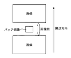
本実施例では、CPU101は、連続画像形成中は、図6に示すように、搬送方向に先行する画像の後端と、後続する画像の先端とに挟まれた非画像領域(以降、画像間と称する。)に、画像濃度検知用画像パターン(パッチ画像)Qを形成させる。尚、以下、パッチ画像の静電潜像を「パッチ潜像」とも称する。このパッチ潜像は、現像器2によって現像化され、現像剤像になる。このパッチ潜像は、常に同じ潜像条件で形成されており、現像剤の状態が同じであれば、現像された現像剤像のトナー濃度は同じになる。
In this embodiment, during the continuous image formation, the
感光ドラム1上のパッチ画像Qの反射光量は、パッチ検知ATRセンサ26で測定される。パッチ検知ATRセンサ26は、LED等の発光素子を備える発光部と、フォトダイオード(PD)等の受光素子を備える受光部を有する。パッチ検知ATRセンサ26は、感光ドラム1上の画像間に形成されたパッチ画像Qがパッチ検知センサ26の下を通過するタイミングを見計らって、上記反射光量を測定する。この測定結果に係る信号は、CPU101に入力される。その後、CPU101は、あらかじめ記録されている濃度変換テーブルを用いてパッチ濃度を計算し、所望の濃度(反射光量)が得られると推定される補給トナー量の補正量を求める。本実施例では、濃度変換テーブルで変換されるパッチ濃度は、その値が小さいほど、パッチ現像剤像のトナー量は多い。例えば、現像剤が初期のときのパッチ濃度が500で、測定したパッチ濃度が400の場合は、初期と比較してパッチのトナー濃度が濃くなったことを示している。
The reflected light amount of the patch image Q on the
本実施例では、通常の画像形成中に非画像領域にパッチ画像Qを形成し、その濃度を検出して補給トナー量を計算し、出力される画像信号値を随時補正するように制御する。 In this embodiment, a patch image Q is formed in a non-image area during normal image formation, the density of the patch image Q is detected, the amount of replenished toner is calculated, and the output image signal value is corrected as needed.
次に、ビデオカウントATRを用いたトナー補給制御について説明する。本実施例では、ビデオカウントATRとパッチ検知ATRとにより、下記式1から補給トナー量Mが求められる。
(補給トナー量:M)=Mv+Mp ・・・(式1)
ここで、Mvは、ビデオカウントATRにより求まる補給トナー量であり、Mpはパッチ検知ATRにより求まる補給トナー量(以降、補給補正量と称する。)である。補給補正量は、上述のように、初期の現像剤でのパッチ画像Qの濃度の検知値を基準として、その基準値と測定結果との差分ΔDから求まる。例えば、初期の現像剤でのパッチ画像Qの濃度:Dp(初期)=500で、画像形成装置がX枚目に出力した際に測定したパッチ画像Qの濃度:Dp(X)=400の場合は、
ΔDp(X)=Dp(X)−Dp(初期)=−100 ・・・(式2)
となる。即ち、例えば、現像器2内のトナーが基準値より1g(基準量)分ずれた時のパッチ画像Qの濃度の測定結果の変化量:ΔD(基準)とし、このΔD(基準)は、ROM102に記憶されている。これにより、CPU101は、下記式3から補給補正量Mpを求める。
Mp=ΔDp(X)/ΔDp(基準) ・・・(式3)
また、Mv(以降、「基礎補給量」と称する。)は、出力される画像信号から求められる。このビデオカウント値は、予め記録されているビデオカウント値と補給トナー量との関係を示すテーブルを用いて、基礎補給量Mvへと換算される。このテーブルは、ROM102に予め記憶されている。こうして、画像形成を行うごとに各画像の基礎補給量Mvが算出される。
Next, toner supply control using the video count ATR will be described. In this embodiment, the replenishment toner amount M is obtained from the
(Supply toner amount: M) = Mv + Mp (Expression 1)
Here, Mv is a replenishment toner amount obtained from the video count ATR, and Mp is a replenishment toner amount obtained from the patch detection ATR (hereinafter referred to as a replenishment correction amount). As described above, the replenishment correction amount is obtained from the difference ΔD between the reference value and the measurement result with reference to the detected value of the density of the patch image Q with the initial developer. For example, the density of the patch image Q in the initial developer: D p (initial) = 500, and the density of the patch image Q measured when the image forming apparatus outputs the Xth sheet: D p (X) = 400 In the case of,
ΔD p (X) = D p (X) −D p (initial) = − 100 (Expression 2)
It becomes. That is, for example, the change amount of the measurement result of the density of the patch image Q when the toner in the developing
Mp = ΔD p (X) / ΔD p (reference) (Formula 3)
Further, Mv (hereinafter referred to as “basic supply amount”) is obtained from the output image signal. This video count value is converted into a basic replenishment amount Mv using a table indicating the relationship between the video count value recorded in advance and the replenishment toner amount. This table is stored in the
以上のようにして、制御部100のCPU101は、式1により補給トナー量Mを求める。即ち、本実施例では、感光ドラム1上の静電潜像はデジタル方式で形成される。そして、トナー補給動作は、パッチ検知ATRセンサ26の検知結果に加えて、感光ドラム1上に形成される静電潜像の画素毎のデジタル画像信号に基づいて行われる。
As described above, the
<自動階調補正処理>
次に、図7を参照して、自動階調補正処理について説明する。自動階調補正処理では、原稿読取部500を用いて記録材P上に形成された階調画像の画像濃度を読み取り、画像階調特性を合わせる手法について述べるが、原稿読取部500の代わりに、他の濃度センサを用いてもよい。画像形成装置の操作部上に設けられた、自動階調補正というモード設定ボタンを押すことで、本制御がスタートする。なお、本実施例では、表示器300は図8乃至図10に示すようなプシュセンサ付きの液晶操作パネル(タッチパネルディスプレイ)で構成されており、直接表示器300に対して操作を行うことができる。
<Automatic gradation correction processing>
Next, automatic gradation correction processing will be described with reference to FIG. In the automatic gradation correction process, a method of reading the image density of the gradation image formed on the recording material P using the
まず、自動階調補正というモード設定ボタンが押されると、表示器300上にテストプリント1のプリントスタートボタン301が現れる(図8(a))。プリントスタートボタン301が押されると、S701において、画像形成装置は、テストプリント1の画像をプリントアウトする。このとき、テストプリント1を形成するための用紙の有無をCPU101が判定し、ない場合は図8(b)に示すような警告表示を行う。このテストプリント1の形成時において、コントラスト電位(後述する)は、環境に応じた標準状態のものを初期値として登録しておき、これを用いる。
First, when a mode setting button called automatic gradation correction is pressed, a
また、本実施例に係る画像形成装置は、複数の用紙カセットを備え、B4、A3、A4、B5等複数種類の用紙サイズが選択可能となっている。しかし、この制御で使用するプリント用紙(記録材)は、後の読み取り作業時に、縦置き、横置きの間違えによるエラーを避けるために、いわゆるラージサイズ紙を用いている。すなわち、B4、A3、11×17、LGRを用いるように設定されている。 The image forming apparatus according to this embodiment includes a plurality of paper cassettes, and a plurality of types of paper sizes such as B4, A3, A4, and B5 can be selected. However, the print paper (recording material) used in this control uses so-called large-size paper in order to avoid errors caused by mistakes in portrait orientation and landscape orientation during subsequent reading operations. That is, it is set to use B4, A3, 11 × 17, and LGR.
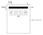
ここで、テストプリント1に形成されるテストパターン1を図11に示す。テストパターン1には、Y、M、C、Bk4色分の中間階調濃度による、帯状のパターン305を形成する。このパターン305を目視で検査することにより、スジ状の異常画像、濃度ムラ、色ムラがないことを確認する。図11に示すように、パターン305の長手方向(主走査方向)のサイズは、後述するパッチパターン306、及び図12に示すテストプリント2用の階調パターン307、308をカバーするようにCCDセンサの主走査方向のサイズが設定されている。一方、パターン306はY、M、C、Bkの各色の最大濃度パッチで、濃度信号値で255レベルを用いる。
Here, a
異常が認められる場合には、再度テストプリント1のプリントを行い、再度異常が認められた場合にはサービスマンコールとする。なお、この帯パターン305を、原稿読取部500で読み取り、その長手方向の濃度情報により、以後の制御を行うかどうかの可否判定を行うことも可能である。
If an abnormality is recognized, the
次に、S702において、出力したテストプリント1の画像を、原稿台ガラス501上に図13のように載せられ、図9(a)に示される読取スタートボタン302が押される。このとき、図9(a)に示す操作者用のガイダンスが表示される。
In step S702, the output image of the
図13は、原稿台を上部から見た図であり、左上のくさび型マークTが原稿台の原稿つき当て用のマークを示す。操作者は、帯パターン305が、つき当てマークT側にくるようにして、なおかつ、表裏を間違えないようにテストプリント1を原稿台に載置する必要がある。操作パネル上では、図9(a)に示すように、例えば、「出力されたテストプリント1を、黒い帯のある方を左側にして原稿台にふせ、読み込みキーを押してください。」とのメッセージが表示される。このようなメッセージを表示することで、置き間違えによる制御エラーを防ぐことができる。
FIG. 13 is a view of the document table as viewed from above, and a wedge-shaped mark T at the upper left indicates a mark for placing a document on the document table. The operator needs to place the
原稿読取部500は、パターン306を読み取る際に、つき当てマークTから徐々に走査し、図11に示すように、最初にパターン305の角Aが得られるので、その座標ポイントから、相対座標で、パターン306の各パッチの位置を算出し(予測し)、パターン306の濃度値を読み取る。つまり、原稿読取部500は、パターン305の角Aを読み取ることによって、パターン306の読み取りを開始するタイミングを予測することができる。
When reading the
読み取り中は、図9(b)に示す表示が行われ、テストプリント1の向きや位置が不正確で読み取り不能のときは図9(c)に示すメッセージが表示され、操作者がテストプリント1を載置し直して、読取スタートボタン302を押すと、再度読み取りが行われる。
During reading, the display shown in FIG. 9B is performed. When the orientation and position of the
得られたRGB値から、光学濃度を換算するためには、下式(4)を用いる。
M=−km×log10(G/255)、
C=−kc×log10(R/255)、
Y=−ky×log10(B/255)、
Bk=−kbk×log10(G/255) ・・・式(4)
ここでは、市販の濃度計と同じ値にするために、補正係数(k)で調整している。また、別にLUTを用いてRGBの輝度情報からMCYBkの濃度情報に変換してもよい。CPU101は、式4によって得られた各色の濃度値:D1(D1(M)、D1(C)、D1(Y)、D1(Bk))をRAM103に記録させる。
In order to convert the optical density from the obtained RGB values, the following equation (4) is used.
M = −km × log 10 (G / 255),
C = −kc × log 10 (R / 255),
Y = −ky × log 10 (B / 255),
Bk = −kbk × log 10 (G / 255) (4)
Here, in order to make it the same value as a commercially available densitometer, it adjusts with the correction coefficient (k). Alternatively, RGB luminance information may be converted into MCYBk density information using an LUT. The
次に、S703において、CPU101は、コントラスト電位Vcount(target)を算出する。図15にコントラスト電位Vcontと濃度値Dとの関係を示す。コントラスト電位Vcontとは、レーザ光強度Lのときの表面電位センサ13の値V(L)と現像バイアスの直流電圧V(DevDC)の差で求められる。V(L)=−300V、V(DevDC)=−520Vのときは、Vcontは、Vcont=V(L)−V(DevDC)=220Vである。
In step S <b> 703, the
図15に示すように、濃度値Dが1.6近傍では、コントラスト電位Vcontと濃度値Dの関係が線形性を有している。濃度値Dが2.0付近になるとこの線形性が保てなくなってきているのは、原稿読取部500の読取精度と、現像効率の低下によるものであり、原稿読取部500や画像形成装置の構成によってこの領域は変化し得る。また、濃度値Dが1.6近傍では、コントラスト電位Vcontと濃度値Dとの関係が線形性を有しているため、ある一点のコントラスト電位Vcontと濃度値D1との関係が分かれば、所望の濃度値になるための必要コントラスト電位Vcont(target)を知ることができる。
As shown in FIG. 15, when the density value D is near 1.6, the relationship between the contrast potential Vcont and the density value D is linear. The reason why the linearity cannot be maintained when the density value D is close to 2.0 is due to a decrease in reading accuracy of the
上記の関係より、最大濃度信号値が255のときの目標濃度D(target)と、テストプリント1時のコントラスト電位Vcont1と、D1とを用いて、コントラスト電位:Vcont(target)を式(5)のように表すことができる。
Vcont(target)=a×Vcont1/D1×D(target) ・・・式(5)
ここで、aは図の傾きから求められる係数であり、D(target)、Vcont1と共に、予めROM102に記録されている。本実施例では、D(target)=1.6としているが、他の値でもよい。ただし、D(target)をあまり高くしすぎると、図15の関係より精度が落ちる可能性がある。このように、D1の測定値が分かれば、Vcont(target)が得られる。
From the above relationship, using the target density D (target) when the maximum density signal value is 255, the contrast potential Vcont1 at the time of the
Vcont (target) = a × Vcont1 / D1 × D (target) (5)
Here, a is a coefficient obtained from the inclination of the figure, and is recorded in advance in the
次に、S704において、CPU101は、レーザ強度L1を測定する。図16に、レーザ光強度Lと感光ドラム電位V(L)(表面電位センサ13の値)の関係を示す。図16に示すように、CPU101は、Vcont(target)が得られる時のレーザ光強度L1を求め、RAM103に記録する。また、このときに、Vcont(target)とVcont1の比Vcont(target)/Vcont1をVrate値として、RAM103に記録する。Vrateを記録しておけば、環境変動でVcont値を変える必要がある際にも、ROM102に記録されているデータを用いて対応が可能である。
Next, in S704, the
ここで、S705において、CPU101は、L1が255以内で収束するか否かを判定する。収束する場合はS706に進み、収束しない場合はS709に進んでエラーフラグを設定する。具体的には、レーザ光強度Lが255になっても、Vcont(target)が得られない場合には、画像形成装置内に不具合がある可能性があるため、S709においてエラーフラグを設定する。さらに、所定のサービスモードで当該エラーフラグをサービスマンが見られるようにしておくことが望ましい。
Here, in S705, the
次に、S706において、CPU101は、テストプリント2を出力する。図10(a)に示すように、操作パネル上には、テストプリント2の画像のプリントスタートボタン303が表示され、それを押すことで図12のテストプリント2の画像がプリントアウトされる。プリント中は図10(b)のような表示となる。
In step S <b> 706, the
テストプリント2は、図12に示すように、Y、M、C、Bkの各色、4列16行の全部で64階調分のグラデーションのパッチ群により構成される。ここで、64階調分は、全部で256階調あるうちの、濃度の低い領域を重点的にレーザ出力レベルを割り当ててあり、高濃度領域は、レーザ出力レベルを間引いてある。このようにすることにより、特にハイライト部における階調特性を良好に調整することができる。
As shown in FIG. 12, the
図12において、307は解像度200lpi(lines/inch)のパッチ、308は400lpi(lines/inch)のパッチである。各解像度の画像を形成するためには、パルス幅変調回路(不図示)において、処理の対象となっている画像データとの比較に用いられる三角波の周期を複数用意することによって実現できる。
In FIG. 12,
なお、本画像形成装置では、階調画像を200lpiの解像度で形成し、文字等の線画像を400lpiの解像度で形成している。この2種類の解像度で同一の階調レベルのパターンを出力しているが、解像度の違いで、階調特性が大きく異なる場合には、解像度に応じて先の階調レベルを設定することがより好ましい。 In this image forming apparatus, a gradation image is formed with a resolution of 200 lpi, and a line image such as a character is formed with a resolution of 400 lpi. The same gradation level pattern is output at these two resolutions, but if the gradation characteristics differ greatly due to the difference in resolution, it is more likely to set the previous gradation level according to the resolution. preferable.
次に、S707において、テストプリント2が原稿台に載置され、読み取りが開始される。図14は、テストプリント2の出力を、原稿台ガラス501上に置いたときに、上方から見た模式図であり、左上のくさび型マークTが原稿台の原稿つき当て用のマークを示す。操作者は、Bkのパターンが、つき当てマークT側にくるように、かつ、表裏を問違えないようにテストプリント2を載置する必要がある。そのため、操作パネル上では、図10(c)に示すメッセージが表示される。これにより、置き間違えによる制御エラーを防ぐことができる。
In step S707, the
原稿読取部500は、パターンを読み取る際に、つき当てマークTから徐々に走査し、最初の濃度ギャップが得られる座標ポイントから、相対座標でパターンの各色パッチの位置を割り出して、読み取る。1パッチ(図12の309)あたりの読むポイントとしては、1パッチ内部の読取ポイントを16ポイント設定し、得られた信号を平均する。ポイント数は読取装置、画像処理装置によって最適化してもよい。
When reading the pattern, the
各パッチ毎に16ポイントの値が平均されたRGB信号を、先に示した光学濃度への変換方法により、濃度値に直し、それを出力濃度として、横軸に画像信号値をプロットしたのが、図17である。図17のターゲット曲線がこの画像形成装置が求める最適な濃度階調特性であるが、測定された曲線はズレが生じている。したがって、S708において、CPU101は、測定曲線がターゲット曲線に合うようにγLUTを変更することで自動階調補正が終了する。
The RGB signal obtained by averaging the 16-point values for each patch is converted into the density value by the conversion method to the optical density described above, and this is used as the output density, and the image signal value is plotted on the horizontal axis. FIG. The target curve in FIG. 17 is the optimum density gradation characteristic required by the image forming apparatus, but the measured curve is misaligned. Therefore, in step S708, the
<第1実施例>
以下では、図18乃至図21を参照して、本発明における第1実施例について説明する。上述したように、自動階調補正後にトナー帯電特性等の現像剤の状態が変化すると、最適な濃度階調特性を維持できなくなるケースがある。具体的な検証結果を図18に示す。図18では、横軸に出力枚数(A4サイズ)、縦軸にそれぞれ本実施例における画像形成装置のパッチ検知ATRセンサ26の検知結果、感光ドラム1上の現像剤像のトナー帯電特性Q/M、画像信号255の単色トナー画像の反射濃度(測定は、X−Rite社の反射濃度計を使用)の測定結果とVcont設定値の推移を示す。摩擦帯電量Q/Mの測定方法は、感光ドラム1上の現像剤像を吸引し、吸引したトナーの電荷量Qとトナー重量Mをそれぞれ測定することによって求められる。
<First embodiment>
The first embodiment of the present invention will be described below with reference to FIGS. As described above, when the developer state such as the toner charging characteristic changes after the automatic gradation correction, there are cases where the optimum density gradation characteristic cannot be maintained. A specific verification result is shown in FIG. In FIG. 18, the horizontal axis represents the number of output sheets (A4 size), the vertical axis represents the detection result of the patch detection ATR sensor 26 of the image forming apparatus in this embodiment, and the toner charging characteristic Q / M of the developer image on the
ここで、Vcontが一定の場合でのパッチ検知信号値、Q/M、反射濃度の関係について述べる。パッチ潜像は常に同じ潜像条件で行われるため、ドラム上のパッチ画像(基準現像剤像)のトナー濃度からQ/Mを知ることができる。パッチ検知信号値が小さい場合、感光ドラム上のトナー濃度が高くなっているので、Q/Mは低下している。また、感光ドラム上のパッチ画像のトナー濃度が高いため、出力されるトナー画像の反射濃度は高くなる。逆に、パッチ検知信号値が高い場合、Q/Mは上昇しており、トナー画像の反射濃度は低くなる。 Here, the relationship between the patch detection signal value, Q / M, and reflection density when Vcont is constant will be described. Since the patch latent image is always performed under the same latent image conditions, the Q / M can be known from the toner density of the patch image (reference developer image) on the drum. When the patch detection signal value is small, since the toner density on the photosensitive drum is high, Q / M is low. Further, since the toner density of the patch image on the photosensitive drum is high, the reflection density of the output toner image is high. Conversely, when the patch detection signal value is high, Q / M increases and the reflection density of the toner image decreases.
図18の▼の位置(10万枚使用時)でパッチ検知信号値が急激に減少し、Q/Mが急激に低下していることがわかる。これは、画像形成装置を1週間使用しなかったために、トナー帯電量が低下したためである。このときには、紙上濃度の値が急激に上昇している。その後、50枚程度でパッチ検知信号値、Q/Mが元の水準に戻ったときには、紙上濃度も元の水準に戻っている。そこで、図18に示すように、▼の位置で紙上濃度が変動しているために自動階調補正を行って、濃度を合わせようとした場合、Q/Mが低下しているためVcontを下げてしまう。したがって、図18の破線に示す通りパッチ検知信号値、Q/Mが元の水準に戻っていくにつれて、紙上濃度が低下してしまい、その後も紙上濃度は低下したままになってしまう。 It can be seen that the patch detection signal value sharply decreases and Q / M rapidly decreases at the position ▼ in FIG. 18 (when 100,000 sheets are used). This is because the toner charge amount decreased because the image forming apparatus was not used for one week. At this time, the on-paper density value increases rapidly. Thereafter, when the patch detection signal value and Q / M return to the original level after about 50 sheets, the on-paper density also returns to the original level. Therefore, as shown in FIG. 18, since the on-paper density fluctuates at the position of ▼, when automatic gradation correction is performed to try to match the density, V / cont is lowered because Q / M is lowered. End up. Therefore, as shown by the broken line in FIG. 18, as the patch detection signal value Q / M returns to the original level, the density on the paper decreases, and the density on the paper remains lowered thereafter.
このような問題を解決するために、本実施例では、図19に示すように、自動階調補正の指示が来てから自動階調補正処理へを移行する前に、トナー帯電特性を確認し、所定の範囲に調整する「自動階調補正準備処理」へ移行する。「自動階調補正準備処理」を行うことで、常に所定の範囲内のトナー帯電特性において自動階調補正を実行することができ、上記問題を解決することができる。ここで、「自動階調補正準備処理」とは、画像形成に先立って行われる階調補正制御を行う前に行われる準備動作であり、現像器内の現像剤のT/D比を所定の範囲内となるように復帰させるモードである。具体的には、画像形成前にパッチ画像を形成して、パッチ画像の濃度に基づいて、現像器へトナーを補給するトナー補給動作、感光ドラムへトナーを吐き出す吐き出し動作、及び現像器の空回転動作の少なくとも1つの動作が実行される。 In order to solve such a problem, in this embodiment, as shown in FIG. 19, the toner charging characteristics are confirmed before the automatic gradation correction process is started after the automatic gradation correction instruction is received. Then, the process proceeds to “automatic gradation correction preparation process” for adjusting to a predetermined range. By performing “automatic gradation correction preparatory processing”, automatic gradation correction can always be performed with toner charging characteristics within a predetermined range, and the above problem can be solved. Here, the “automatic gradation correction preparation process” is a preparatory operation performed before gradation correction control performed prior to image formation, and the T / D ratio of the developer in the developing device is set to a predetermined value. This is a mode for returning to be within the range. Specifically, a patch image is formed before image formation, and a toner supply operation for supplying toner to the developing device based on the density of the patch image, a discharging operation for discharging toner to the photosensitive drum, and idling of the developing device At least one of the operations is performed.
本実施例においては、パッチ検知信号値からトナー帯電量が所定な範囲であるか否かを確認し、トナー帯電量が所定の範囲を外れている場合は、トナー帯電量が所定の範囲内になるように現像器内の現像剤の状態を整えてから自動階調補正を実施する。この手法を用いれば、自動階調補正後にトナー帯電量の変化による濃度階調特性の変化を抑えることができる。 In this embodiment, it is confirmed from the patch detection signal value whether or not the toner charge amount is within a predetermined range. If the toner charge amount is outside the predetermined range, the toner charge amount is within the predetermined range. Thus, automatic gradation correction is performed after the state of the developer in the developing device is adjusted. By using this method, it is possible to suppress changes in density gradation characteristics due to changes in toner charge amount after automatic gradation correction.
以下に、具体的な方法について図1及び図20のフローチャートを参照して説明する。自動階調補正というモード設定ボタンが押されると、自動階調補正の実行指示がCPU101に伝達される。CPU101は、表示器300上にテストプリント1の出力表示を出す前に、自動階調補正準備中の表示を出力する。それと同時に、S2001において、CPU101は、パッチ画像を作像させる指示を送り、読み取られたパッチ検知信号値DpnをRAM103に記録する。
A specific method will be described below with reference to the flowcharts of FIGS. When a mode setting button called automatic gradation correction is pressed, an automatic gradation correction execution instruction is transmitted to the
次に、S2002において、CPU101は、RAM103に記録されている初期の現像剤でのパッチ検知信号値Dp(初期)の値(基準値)を読み出して、DpnとDp(初期)の値の比較を行う。両者の差が大きければ、現像剤の帯電特性は基準値から大きくずれていると判定できる。つまり、
|Dpn−Dp(初期)|>=A1(閾値)
であれば、現像剤の帯電特性は基準値から大きくずれていると判定(Yes)し、S2003に進む。本実施例では、A1=30としたが、他の値でもよい。この値は、Q/Mが初期値より2μC/g変化している場合である。A1の値を小さくすることで、現像剤の帯電特性をより合わせた条件で自動階調補正を実行することができる。一方、S2002の条件を満たさない場合(No)はS2006に進み、このまま自動階調補正を実行する。
Next, in S2002, the
| D pn −D p (initial) |> = A1 (threshold value)
If it is, it is determined that the charging characteristic of the developer is greatly deviated from the reference value (Yes), and the process proceeds to S2003. In this embodiment, A1 = 30, but other values may be used. This value is when Q / M changes by 2 μC / g from the initial value. By reducing the value of A1, automatic gradation correction can be executed under conditions that better match the charging characteristics of the developer. On the other hand, if the condition of S2002 is not satisfied (No), the process proceeds to S2006, and automatic gradation correction is executed as it is.
次に、S2003において、CPU101は、現像剤の帯電特性(帯電量)が基準値以下であるか否かを判定する。Dpn<=Dp(初期)の場合には、Q/Mが初期値より下がっていることを意味する。この場合、即ち、S2003の条件を満たす場合(Yes)は、S2004に進む。一方、S2003の条件を満たさない場合(No)、Q/Mが初期値より上がっているため、S2007に進み、Q/Mを下げる調整処理を実行する。Q/Mを下げるためには、現像剤中のトナーを補給して現像剤(Dev)中のトナー(T)の比T/Devを上げる必要がある。トナーを補給した後は、現像剤中のQ/M分布は不均一の状態であり、空回転動作を行い現像剤をよく攪拌することで、T/DevにあったQ/Mの値に調整し、Q/M分布を均一にすると共にQ/Mの値を下げることができる。
In step S <b> 2003, the
S2004において、CPU101は、空回転動作を行うか、又は、トナー吐き出しを行うかの判定を行う。具体的には、CPU101は、RAM103から、Dpnの1つ前に形成された、即ち、前回形成されたパッチ画像(基準現像剤像)のパッチ検知信号値Dpn−1を読み出し、今回形成したパッチ画像のパッチ検知信号値DpnとDpn−1の値を比較する。
In step S2004, the
以下のように、S2004において、
Dpn−1−Dpn>=A2
の関係が成り立つ場合(Yes)、パッチ検知ATRの制御間隔である短い期間にQ/Mが急激に低下していることになり、この場合はパッチ検知ATRの制御間隔で現像剤の放置がなされているとほぼ断定できる。したがって、トナー吐き出しを行うより空回転によって現像剤を攪拌することによってQ/Mを上昇させる方が良いと判定できるため、空回転動作を実施する。尚、空回転時間は1分間としたが、他の時間でもよい。
In S2004, as follows:
D pn-1 −D pn > = A2
If the above relationship is satisfied (Yes), Q / M is drastically decreased in a short period which is the control interval of the patch detection ATR. In this case, the developer is left unattended at the control interval of the patch detection ATR. It can almost be determined that Therefore, since it can be determined that it is better to raise the Q / M by stirring the developer by idling rather than discharging the toner, idling is performed. Although the idling time is 1 minute, other time may be used.
一方、S2004の条件を満たさない場合(No)、パッチ検知ATRの制御間隔でQ/Mの低下は大きくなく、放置の影響は小さいと判定できる。よって、S2007に進み、空回転動作はせずに現像剤中のトナーを感光ドラム1上に吐き出して、現像剤(Dev)中のトナー(T)の比T/Devを下げることでQ/Mを上げる工程を行う。ここでは、現像剤中のトナーを感光ドラム1上に吐き出す工程において、T/Devを下げながら現像剤を攪拌しているので、空回転動作は必要ない。尚、本実施例では、A2=15としたが、他の値でもよい。ただし、A1>=A2を満たす必要がある。
On the other hand, when the condition of S2004 is not satisfied (No), it can be determined that the Q / M decrease is not large at the control interval of the patch detection ATR and the influence of neglect is small. Therefore, the process proceeds to S2007, and the toner in the developer is discharged onto the
ここで、S2007において、S2003を満たさない場合(No)とS2004を満たさない場合(No)におけるトナー補給量又はトナー吐き出し量について説明する。S2007のトナー補給量又はトナー吐き出し量については、パッチ検知信号値DpnとDp(初期)と上述した式(3)より、補給補正量Mp分補給又は吐き出せば良いため、吐き出し量/補給量はMp分とする。 Here, in S2007, the toner replenishment amount or the toner discharge amount when S2003 is not satisfied (No) and when S2004 is not satisfied (No) will be described. With regard to the toner replenishment amount or the toner discharge amount in S2007, the discharge amount / replenishment amount can be obtained from the patch detection signal values D pn and D p (initial) and the above-described equation (3), as long as the supply correction amount Mp is replenished or discharged. Is Mp.
S2005又はS2007が終了するとS2008に進み、CPU101は、再度パッチ濃度測定を行い、S2009において測定したパッチ検知信号値Dpn+1が、
|Dpn+1−Dp(初期)|<=A3
を満たすか否かを判定する。満たす場合(Yes)には、現像剤の帯電特性は基準値に復帰したと判定して、S2010に進み、自動階調補正処理を実行し自動階調補正を実行する。本実施例では、A3=10としたが、他の値でもよい。
When S2005 or S2007 ends, the process proceeds to S2008, where the
| D pn + 1 −D p (initial) | <= A3
It is determined whether or not the above is satisfied. If it is satisfied (Yes), it is determined that the charging characteristics of the developer have returned to the reference value, and the process proceeds to S2010, where automatic gradation correction processing is executed and automatic gradation correction is executed. In this embodiment, A3 = 10, but other values may be used.
一方、S2009の条件を満たさない場合(No)には、S2002に戻って現像剤の帯電特性の調整動作を行う。この際には、n=n+1となり、以後n+1,2,3,4,5とこのサイクルを繰り返す度に数値が上がっていく。なお、n=n+5になっても、S2009の条件を満たさない場合、トナーが劣化しているために現像剤の帯電能力が低下している恐れがある。したがって、この場合には現像剤中のトナーを一度感光ドラム上に吐き出して、新しいトナーを補給する「トナー入れ替え処理」を実施し、現像剤の帯電能力を復帰させる。例えば、現像剤(Dev)中のトナー(T)の比T/Devで2%のトナー量入れ替えを行うことが望ましいが、この量は他の値でもよい。「トナー入れ替え処理」実施後、S2005に戻って現像剤の帯電特性の調整動作を行う。 On the other hand, when the condition of S2009 is not satisfied (No), the process returns to S2002 to perform the operation of adjusting the charging characteristics of the developer. At this time, n = n + 1, and thereafter, the numerical value increases every time this cycle is repeated, such as n + 1, 2, 3, 4, and 5. Even when n = n + 5, if the condition of S2009 is not satisfied, the charging ability of the developer may be reduced because the toner has deteriorated. Therefore, in this case, the toner in the developer is once discharged onto the photosensitive drum, and a “toner replacement process” for supplying new toner is performed to restore the developer charging ability. For example, it is desirable to change the toner amount by 2% at the ratio T / Dev of the toner (T) in the developer (Dev), but this amount may be another value. After performing the “toner replacement process”, the process returns to S2005 to perform an operation for adjusting the charging characteristics of the developer.
さらに、n=n+10になってもS2009の条件を満たさない場合、画像形成装置側の不具合がある、特に、パッチ検知ATRセンサ26、現像器2、感光ドラム1、帯電ローラ11、スキャナ12等に不具合がある可能性がある。したがって、CPU101は、「自動階調補正準備処理」を中止し、表示器300上にサービスメンテナンスを促すメッセージを画像形成装置の表示部に表示させる。
Further, if the condition of S2009 is not satisfied even when n = n + 10, there is a problem on the image forming apparatus side. In particular, the patch detection ATR sensor 26, the developing
次に、図21を参照して、本実施例における「自動階調補正準備処理」を実施した際の効果について説明する。図21の▼の位置(10万枚使用時)でパッチ検知信号値が急激に減少し、Q/Mが急激に低下していることがわかる。このときには、紙上濃度の値が急激に上昇したため、自動階調補正を実施した。その際に、本実施例における「自動階調補正準備処理」を実施したのが実線と黒丸、実施していないのが破線と白抜き丸である。図21に示すように、「自動階調補正準備処理」を実施していない場合(破線と白抜き丸)では、自動階調補正時にVcontが低下していることにより、自動階調補正後に紙上濃度が下がってきてしまっている。一方、「自動階調補正準備処理」を実施した場合、自動階調補正後も紙上濃度は安定していることがわかる。以上より、「自動階調補正準備処理」の効果を確認することができた。 Next, with reference to FIG. 21, the effect when the “automatic gradation correction preparation process” in the present embodiment is performed will be described. It can be seen that the patch detection signal value sharply decreases and the Q / M rapidly decreases at the position ▼ in FIG. 21 (when 100,000 sheets are used). At this time, since the on-paper density value suddenly increased, automatic gradation correction was performed. At this time, the “automatic gradation correction preparation process” in the present embodiment is performed with solid lines and black circles, and the lines that are not implemented with broken lines and white circles. As shown in FIG. 21, when the “automatic gradation correction preparation process” is not performed (broken line and white circle), Vcont decreases during automatic gradation correction. The concentration has decreased. On the other hand, when the “automatic gradation correction preparation process” is performed, it is understood that the on-paper density is stable even after the automatic gradation correction. From the above, the effect of “automatic gradation correction preparation processing” could be confirmed.
<第2実施例>
上記第1実施例では、パッチ濃度を測定し、その値を元に「自動階調補正準備処理」を行ったが、この方法では常にパッチ画像を形成する必要がある。パッチ濃度が初期値と多くずれるような状況(長期放置後、環境変動など)ではこの工程を行う必要があるが、画像形成装置を使用中に、より色味を合わせるために自動階調補正を行う場合に上記自動階調補正準備処理を実行する必要はない。つまり、画像形成装置を使用中では、パッチ検知ATR制御により現像剤の帯電特性は所望の範囲内であるため、パッチ画像形成を行うことが無駄になってしまう。そこで、本実施例では、画像形成装置内に設置した温湿度センサやRAM103に画像形成装置の動作記録を記録させ、その結果を用いることで、第1実施例の「自動階調補正準備処理」を行うことが妥当かどうかの判定を行う工程を加える。これにより、上記第1実施例の効果を享受しつつ、自動階調補正を行う際の不必要なダウンタイムや無駄なトナーの消費を低減することができる。
<Second embodiment>
In the first embodiment, the patch density is measured and the “automatic gradation correction preparation process” is performed based on the measured value. However, in this method, it is necessary to always form a patch image. It is necessary to perform this step in situations where the patch density deviates much from the initial value (environmental fluctuations after leaving for a long period of time), but automatic tone correction is performed to better match colors while using the image forming apparatus. When performing, it is not necessary to execute the automatic gradation correction preparation process. In other words, while the image forming apparatus is being used, the patch detection ATR control causes the developer charging characteristics to be within a desired range, so that it is useless to perform patch image formation. Therefore, in this embodiment, the operation record of the image forming apparatus is recorded in the temperature / humidity sensor or
まず、図23を参照して、本実施例における画像形成装置の構成例について説明する。なお、以下では、上記第1実施例と異なる構成及び技術についてのみ説明する。 First, a configuration example of the image forming apparatus according to the present exemplary embodiment will be described with reference to FIG. In the following, only configurations and techniques different from those of the first embodiment will be described.
図23に示すように、本実施例における画像形成装置には、第1実施例の構成に加えて、温湿度センサ701及び時計702を備える。温湿度センサ701は、画像形成装置内の温度、湿度、絶対水分量WのデータをRAM103に記録する。時計702は、プリント信号があったときの時刻と現像器2が動作した時刻をRAM103に記録する。また、本実施例による画像形成装置は、現像剤の使用枚数をRAM103に記録する。
As shown in FIG. 23, the image forming apparatus according to this embodiment includes a temperature /
次に、図22のフローチャートを参照して、本実施例における処理手順について説明する。自動階調補正というモード設定ボタンが押されると、自動階調補正の実行指示がCPU101に伝達される。CPU101は、表示器300上にテストプリント1の出力表示を出す前に、自動階調補正準備中の表示を出力する。それと同時に、S2201において、CPU101は、RAM103から以下の情報(1)〜(5)を読み出す。
(1)直前にプリントされてからの水分の変化量ΔWn
(2)直前にプリントされてからの経過時間(プリント間隔)t1
(3)プリント間隔t1内、即ち、上記経過時間内に現像器2が動作した時間t2
(4)過去1000枚での画像形成領域の割合を示す平均画像デューティー:I(過去1000枚のビデオカウント値の平均値と255信号時のビデオカウント値の比で求められる)
(5)現像剤の使用枚数C(初期剤からの使用枚数)、即ち、画像形成枚数
これらの情報の少なくとも1つを用いて、CPU101は、第1実施例で説明した自動階調補正準備処理を行うか否かを決定する。以下では、これらの情報を用いた決定処理の一例について説明する。なお、以下の決定処理における判定条件とは異なる条件を本発明に適用してもよい。
Next, a processing procedure in the present embodiment will be described with reference to the flowchart of FIG. When a mode setting button called automatic gradation correction is pressed, an automatic gradation correction execution instruction is transmitted to the
(1) Moisture change ΔWn since the last printing
(2) Elapsed time since printing immediately before (print interval) t1
(3) Time t2 when the developing
(4) Average image duty indicating the ratio of the image forming area in the past 1000 sheets: I (determined by the ratio of the average video count value of the past 1000 sheets and the video count value at the time of 255 signals)
(5) Number of used developer sheets C (number of used sheets from the initial agent), that is, the number of image forming sheets. Using at least one of these pieces of information, the
S2202において、CPU101は、まず水分の変化量ΔWnが、
ΔWn<=1g
を満たすか否かを判定する。満たす場合(Yes)は、水分の変化量は多くないと判定して、自動階調補正準備処理を実行することなくS2203に進む。一方、Noの場合はS2207に進み自動階調補正準備処理を実行する。なお、1gの値については、他の値でもよい。
In S2202, the
ΔWn <= 1g
It is determined whether or not the above is satisfied. If it is satisfied (Yes), it is determined that the amount of change in moisture is not large, and the process advances to step S2203 without executing the automatic gradation correction preparation process. On the other hand, in the case of No, the process proceeds to S2207 to execute the automatic gradation correction preparation process. In addition, about the value of 1g, another value may be sufficient.
次に、S2203において、CPU101は、プリント間隔t1が、
t1>=3hr
を満たすか否かを判定する。満たす場合(Yes)は、プリント間隔が3時間以上であるため、放置による影響があると判定してS2204に進む。一方、Noの場合はS2208に進み、環境変動、放置による影響が小さく問題はないと判定して、自動階調補正準備処理を実行することなく自動階調補正を実施する。なお、3hrの値については、他の値でもよい。
Next, in step S2203, the
t1> = 3hr
It is determined whether or not the above is satisfied. If it is satisfied (Yes), the print interval is 3 hours or longer. On the other hand, in the case of No, the process proceeds to S2208, where it is determined that there is no problem due to environmental fluctuation and neglect, and automatic gradation correction is performed without executing automatic gradation correction preparation processing. In addition, about the value of 3hr, another value may be sufficient.
次に、S2204において、CPU101は、プリント間隔t1と現像器2の動作時間t2とが、以下のような関係、
(t2/t1)>=2.1E−2
を満たすか否かを判定する。満たさない場合(No)には、12時間あたり15分以上は現像器2が空回転動作しており、環境変動、放置による影響が小さいと判定できるため、S2209に進み自動階調補正準備処理を実行することなく自動階調補正処理を実行する。なお、2.1E−2の値については、他の値でもよい。一方、Yesの場合は、現像剤の状態によっては、放置による影響がありうるため、S2205に進む。
Next, in step S2204, the
(T2 / t1)> = 2.1E-2
It is determined whether or not the above is satisfied. If it is not satisfied (No), it can be determined that the developing
次に、S2205において、CPU101は、再度プリント間隔t1と現像器2の動作時間t2とが、以下のような関係、
(t2/t1)<=3.5E−4
を満たすか否かを判定する。満たさない場合(No)には、12時間あたり15秒未満の時間しか現像器2が空回転動作しておらず、現像剤が放置により帯電特性が変化している可能性があるため、S2206に進み自動階調補正準備処理を実行する。これにより、現像剤の帯電特性を所望の範囲にする。なお、3.5E−4の値については、他の値でもよい。
Next, in step S2205, the
(T2 / t1) <= 3.5E-4
It is determined whether or not the above is satisfied. If not satisfied (No), the developing
S2204及びS2005の両方を満たす(Yes)場合、つまり現像器2の空回転時間が12時間あたり15秒以上15分未満の場合には、現像剤の状態によっては、放置による影響がありうるため、S2210に進む。
When both S2204 and S2005 are satisfied (Yes), that is, when the idle rotation time of the developing
次に、S2210において、CPU101は、現像剤の使用枚数(初期剤からの使用枚数)、即ち、画像形成枚数が、以下のような関係、
C<=10万枚(A4)
を満たすか否かを判定する。満たす場合(Yes)には、12時間あたり15秒以上15分未満の時間、現像器2が空回転動作していれば、放置による影響が小さい現像剤であると判定できるため、自動階調補正準備処理を実行することなくS2211に進む。なお、10万枚の値については、他の値でもよい。一方、Noの場合は、S2213に進み自動階調補正準備処理を実行する。
In step S <b> 2210, the
C <= 100,000 sheets (A4)
It is determined whether or not the above is satisfied. If satisfied (Yes), if the developing
最後に、S2211において、CPU101は、過去1000枚での平均画像デューティーIが、以下のような関係、
I>=5%
を満たすか否かを判定する。満たす場合(Yes)は、12時間あたり15秒以上15分未満の時間、現像器2が空回転動作していれば、10万枚以上使用していても放置による影響が小さい現像剤であると判定し、S2212に進み自動階調補正準備処理を実行することなく自動階調補正処理を実行する。なお、5%の値については、他の値でもよい。一方、Noの場合は、S2214に進み、自動階調補正準備処理を実行する。
Finally, in S2211, the
I> = 5%
It is determined whether or not the above is satisfied. When satisfied (Yes), if the
以上説明したように、本実施例によれば、必要に応じて自動階調補正準備処理を的確に実施することができるため、不必要なダウンタイムやトナーの消費を低減することができる。 As described above, according to the present embodiment, the automatic gradation correction preparation process can be accurately performed as necessary, so that unnecessary downtime and toner consumption can be reduced.
Claims (6)
前記自動階調補正処理を実行する前に、前記露光手段及び前記現像手段を用いて前記像担持体に基準現像剤像を形成させる形成手段と、
前記像担持体に形成された前記基準現像剤像の濃度を検知する濃度検知手段と、
前記現像手段が有する前記現像剤の帯電量が所定の範囲内であることを前記濃度検知手段の検知結果が示す場合に、前記自動階調補正処理を実行させ、前記現像手段が有する前記現像剤の帯電量が所定の範囲内でないと前記濃度検知手段の検知結果が示す場合に、前記現像手段が有する前記現像剤の帯電量を所定の範囲内にするための調整処理を実行した後に前記自動階調補正処理を実行させる制御手段と
を備え、
前記制御手段は、
前記濃度検知手段によって検知された前記基準現像剤像の濃度値と、前記画像形成装置の記憶手段に予め記憶されている基準値との差分が所定の閾値を超える場合であって、かつ、該濃度値が該基準値以下である場合であって、かつ、前回形成した基準現像剤像の濃度値と比較して今回形成した基準現像剤像の濃度値が所定の閾値を超えて低下していない場合に、前記調整処理として、前記像担持体へトナーを吐き出す吐き出し動作を実行することを特徴とする画像形成装置。 An image carrier, an exposure unit that forms an electrostatic latent image by exposing the image carrier, and a toner and a magnetic carrier as a developer, and the electrostatic latent image formed on the image carrier is developed as a developer. An image forming apparatus that executes an automatic gradation correction process that adjusts density gradation characteristics by reading a gradation pattern formed on a recording material, and developing means for developing an image;
Forming means for forming a reference developer image on the image carrier using the exposure means and the developing means before executing the automatic gradation correction processing;
Density detecting means for detecting the density of the reference developer image formed on the image carrier;
When the detection result of the density detecting means indicates that the charge amount of the developer included in the developing means is within a predetermined range, the developer included in the developing means is caused to execute the automatic gradation correction processing. When the detection result of the density detection means indicates that the charge amount of the developer is not within a predetermined range, the automatic processing is performed after performing adjustment processing for bringing the charge amount of the developer included in the developing unit within the predetermined range. Control means for executing gradation correction processing ,
The control means includes
The difference between the density value of the reference developer image detected by the density detection means and the reference value stored in advance in the storage means of the image forming apparatus exceeds a predetermined threshold; and The density value of the reference developer image formed this time is lower than a predetermined threshold value when compared to the density value of the reference developer image formed previously, and the density value is lower than the reference value. An image forming apparatus that performs a discharge operation for discharging toner to the image carrier as the adjustment process when there is no image.
前記濃度検知手段によって検知された前記基準現像剤像の濃度値と、前記画像形成装置の記憶手段に予め記憶されている基準値との差分が所定の閾値を超える場合であって、かつ、該濃度値が該基準値以下である場合であって、かつ、前回形成した基準現像剤像の濃度値と比較して今回形成した基準現像剤像の濃度値が所定の閾値を超えて低下している場合に、前記調整処理として、前記現像手段に含まれるトナー及び磁性キャリアを撹拌するための空回転動作を実行することを特徴とする請求項1に記載の画像形成装置。 The control means includes
The difference between the density value of the reference developer image detected by the density detection means and the reference value stored in advance in the storage means of the image forming apparatus exceeds a predetermined threshold; and When the density value is equal to or lower than the reference value, and the density value of the reference developer image formed this time is lower than a predetermined threshold value compared with the density value of the reference developer image formed last time, If you are, the adjustment process as the image forming apparatus according to claim 1, characterized in that performing the idling operation for stirring the toner and a magnetic carrier contained in the developing unit.
前記濃度検知手段によって検知された前記基準現像剤像の濃度値と、前記画像形成装置の記憶手段に予め記憶されている基準値との差分が所定の閾値を超える場合であって、かつ、該濃度値が該基準値より大きい場合に、前記調整処理として、前記現像手段へトナーを補給するトナー補給動作を実行した後に前記現像手段に含まれるトナー及び磁性キャリアを撹拌するための空回転動作を実行することを特徴とする請求項1又は2に記載の画像形成装置。 The control means includes
The difference between the density value of the reference developer image detected by the density detection means and the reference value stored in advance in the storage means of the image forming apparatus exceeds a predetermined threshold; and When the density value is larger than the reference value, the adjustment process includes an idling operation for agitating the toner and the magnetic carrier contained in the developing unit after executing a toner replenishing operation for replenishing the toner to the developing unit. The image forming apparatus according to claim 1 , wherein the image forming apparatus is executed.
前記自動階調補正処理を実行する前に、前記露光手段及び前記現像手段を用いて前記像担持体に基準現像剤像を形成させる形成手段と、
前記像担持体に形成された前記基準現像剤像の濃度を検知する濃度検知手段と、
前記現像手段が有する前記現像剤の帯電量が所定の範囲内であることを前記濃度検知手段の検知結果が示す場合に、前記自動階調補正処理を実行させ、前記現像手段が有する前記現像剤の帯電量が所定の範囲内でないと前記濃度検知手段の検知結果が示す場合に、前記現像手段が有する前記現像剤の帯電量を所定の範囲内にするための調整処理を実行した後に前記自動階調補正処理を実行させる制御手段と
を備え、
前記制御手段は、
前記濃度検知手段によって検知された前記基準現像剤像の濃度値と、前記画像形成装置の記憶手段に予め記憶されている基準値との差分が所定の閾値を超える場合であって、かつ、該濃度値が該基準値以下である場合であって、かつ、前回形成した基準現像剤像の濃度値と比較して今回形成した基準現像剤像の濃度値が所定の閾値を超えて低下している場合に、前記調整処理として、前記現像手段に含まれるトナー及び磁性キャリアを撹拌するための空回転動作を実行することを特徴とする画像形成装置。 An image carrier, an exposure unit that forms an electrostatic latent image by exposing the image carrier, and a toner and a magnetic carrier as a developer, and the electrostatic latent image formed on the image carrier is developed as a developer. An image forming apparatus that executes an automatic gradation correction process that adjusts density gradation characteristics by reading a gradation pattern formed on a recording material, and developing means for developing an image;
Forming means for forming a reference developer image on the image carrier using the exposure means and the developing means before executing the automatic gradation correction processing;
Density detecting means for detecting the density of the reference developer image formed on the image carrier;
When the detection result of the density detecting means indicates that the charge amount of the developer included in the developing means is within a predetermined range, the developer included in the developing means is caused to execute the automatic gradation correction processing. When the detection result of the density detection means indicates that the charge amount of the developer is not within a predetermined range, the automatic processing is performed after performing adjustment processing for bringing the charge amount of the developer included in the developing unit within the predetermined range. Control means for executing gradation correction processing;
With
The control means includes
The difference between the density value of the reference developer image detected by the density detection means and the reference value stored in advance in the storage means of the image forming apparatus exceeds a predetermined threshold; and When the density value is equal to or lower than the reference value, and the density value of the reference developer image formed this time is lower than a predetermined threshold value compared with the density value of the reference developer image formed last time, If you are, the adjustment process as the images forming apparatus you and the client performs idling operation for stirring the toner and a magnetic carrier contained in the developing unit.
前記濃度検知手段によって検知された前記基準現像剤像の濃度値と、前記画像形成装置の記憶手段に予め記憶されている基準値との差分が所定の閾値を超える場合であって、かつ、該濃度値が該基準値より大きい場合に、前記調整処理として、前記現像手段へトナーを補給するトナー補給動作を実行した後に前記現像手段に含まれるトナー及び磁性キャリアを撹拌するための空回転動作を実行することを特徴とする請求項4に記載の画像形成装置。 The difference between the density value of the reference developer image detected by the density detection means and the reference value stored in advance in the storage means of the image forming apparatus exceeds a predetermined threshold; and When the density value is larger than the reference value, the adjustment process includes an idling operation for agitating the toner and the magnetic carrier contained in the developing unit after executing a toner replenishing operation for replenishing the toner to the developing unit. The image forming apparatus according to claim 4, wherein the image forming apparatus is executed.
前記自動階調補正処理を実行する前に、前記露光手段及び前記現像手段を用いて前記像担持体に基準現像剤像を形成させる形成手段と、
前記像担持体に形成された前記基準現像剤像の濃度を検知する濃度検知手段と、
前記現像手段が有する前記現像剤の帯電量が所定の範囲内であることを前記濃度検知手段の検知結果が示す場合に、前記自動階調補正処理を実行させ、前記現像手段が有する前記現像剤の帯電量が所定の範囲内でないと前記濃度検知手段の検知結果が示す場合に、前記現像手段が有する前記現像剤の帯電量を所定の範囲内にするための調整処理を実行した後に前記自動階調補正処理を実行させる制御手段と
を備え、
前記制御手段は、
直前に画像形成されてからの水分の変化量、直前に画像形成されてからの経過時間、該経過時間内に前記現像手段が動作した時間、過去の画像形成における画像形成領域の割合を示す平均画像デューティー、及び、画像形成枚数の少なくとも1つの情報を用いて、前記現像手段が有する前記現像剤の帯電量が所定の範囲内であるか否かに関わらず、前記調整処理を実行することなく前記自動階調補正処理を実行させることを決定する決定手段を備えることを特徴とする画像形成装置。 An image carrier, an exposure unit that forms an electrostatic latent image by exposing the image carrier, and a toner and a magnetic carrier as a developer, and the electrostatic latent image formed on the image carrier is developed as a developer. An image forming apparatus that executes an automatic gradation correction process that adjusts density gradation characteristics by reading a gradation pattern formed on a recording material, and developing means for developing an image;
Forming means for forming a reference developer image on the image carrier using the exposure means and the developing means before executing the automatic gradation correction processing;
Density detecting means for detecting the density of the reference developer image formed on the image carrier;
When the detection result of the density detecting means indicates that the charge amount of the developer included in the developing means is within a predetermined range, the developer included in the developing means is caused to execute the automatic gradation correction processing. When the detection result of the density detection means indicates that the charge amount of the developer is not within a predetermined range, the automatic processing is performed after performing adjustment processing for bringing the charge amount of the developer included in the developing unit within the predetermined range. Control means for executing gradation correction processing;
With
The control means includes
Average amount of change in moisture since the last image was formed, elapsed time since the last image was formed, time during which the developing unit was operated within the elapsed time, and ratio of image forming area in past image formation Regardless of whether or not the charge amount of the developer included in the developing unit is within a predetermined range using at least one information of the image duty and the number of formed images, the adjustment process is not executed. images forming device you further comprising a determining means for determining possible to execute the automatic gradation correction process.
Priority Applications (2)
| Application Number | Priority Date | Filing Date | Title |
|---|---|---|---|
| JP2010279857A JP5767463B2 (en) | 2010-12-15 | 2010-12-15 | Image forming apparatus |
| US13/306,438 US8639135B2 (en) | 2010-12-15 | 2011-11-29 | Image forming apparatus |
Applications Claiming Priority (1)
| Application Number | Priority Date | Filing Date | Title |
|---|---|---|---|
| JP2010279857A JP5767463B2 (en) | 2010-12-15 | 2010-12-15 | Image forming apparatus |
Publications (2)
| Publication Number | Publication Date |
|---|---|
| JP2012128200A JP2012128200A (en) | 2012-07-05 |
| JP5767463B2 true JP5767463B2 (en) | 2015-08-19 |
Family
ID=46234597
Family Applications (1)
| Application Number | Title | Priority Date | Filing Date |
|---|---|---|---|
| JP2010279857A Expired - Fee Related JP5767463B2 (en) | 2010-12-15 | 2010-12-15 | Image forming apparatus |
Country Status (2)
| Country | Link |
|---|---|
| US (1) | US8639135B2 (en) |
| JP (1) | JP5767463B2 (en) |
Families Citing this family (10)
| Publication number | Priority date | Publication date | Assignee | Title |
|---|---|---|---|---|
| JPS6179849A (en) * | 1984-09-25 | 1986-04-23 | Mitsubishi Electric Corp | Oil-up preventing mechanism in stirling engine |
| JP5484085B2 (en) * | 2010-01-18 | 2014-05-07 | キヤノン株式会社 | Image forming apparatus and image quality correction method thereof |
| JP2013101015A (en) * | 2011-11-08 | 2013-05-23 | Canon Inc | Examination device, examination method, examination system, computer program |
| JP6195149B2 (en) * | 2013-05-14 | 2017-09-13 | 株式会社リコー | Image forming apparatus |
| JP6391220B2 (en) * | 2013-08-19 | 2018-09-19 | キヤノン株式会社 | Image forming apparatus |
| JP6429496B2 (en) * | 2014-05-23 | 2018-11-28 | キヤノン株式会社 | Image forming apparatus |
| JP6440424B2 (en) * | 2014-09-18 | 2018-12-19 | キヤノン株式会社 | Image forming apparatus |
| JP6737228B2 (en) * | 2017-04-27 | 2020-08-05 | 京セラドキュメントソリューションズ株式会社 | Image forming device |
| JP7251080B2 (en) * | 2018-09-19 | 2023-04-04 | コニカミノルタ株式会社 | image forming device |
| JP2022182355A (en) * | 2021-05-28 | 2022-12-08 | キヤノン株式会社 | Image forming apparatus |
Family Cites Families (11)
| Publication number | Priority date | Publication date | Assignee | Title |
|---|---|---|---|---|
| JPH1039608A (en) | 1996-07-22 | 1998-02-13 | Canon Inc | Picture image forming device |
| JP3484677B2 (en) * | 1997-01-08 | 2004-01-06 | 株式会社リコー | Image forming device |
| JP2000003104A (en) * | 1998-06-12 | 2000-01-07 | Ricoh Co Ltd | Method for image forming and device therefor |
| JP3441994B2 (en) * | 1999-02-24 | 2003-09-02 | キヤノン株式会社 | Image processing apparatus and control method thereof |
| JP4269641B2 (en) * | 2002-10-25 | 2009-05-27 | 富士ゼロックス株式会社 | Density adjusting device and image forming apparatus using the same |
| JP4656598B2 (en) * | 2003-12-02 | 2011-03-23 | 富士ゼロックス株式会社 | Image forming apparatus, calibration method, and program thereof |
| JP2006189795A (en) * | 2004-12-09 | 2006-07-20 | Canon Inc | Image forming apparatus and image-adjusting method |
| JP2007081898A (en) * | 2005-09-15 | 2007-03-29 | Ricoh Co Ltd | Image forming apparatus |
| JP5388513B2 (en) | 2008-09-08 | 2014-01-15 | キヤノン株式会社 | Image forming apparatus |
| JP5365332B2 (en) * | 2009-04-30 | 2013-12-11 | 株式会社リコー | Image forming apparatus, correction method, program, and recording medium |
| US20110143272A1 (en) * | 2009-12-16 | 2011-06-16 | Kabushiki Kaisha Toshiba | Image forming apparatus and image stabilization control method used in image forming apparatis |
-
2010
- 2010-12-15 JP JP2010279857A patent/JP5767463B2/en not_active Expired - Fee Related
-
2011
- 2011-11-29 US US13/306,438 patent/US8639135B2/en not_active Expired - Fee Related
Also Published As
| Publication number | Publication date |
|---|---|
| JP2012128200A (en) | 2012-07-05 |
| US8639135B2 (en) | 2014-01-28 |
| US20120155898A1 (en) | 2012-06-21 |
Similar Documents
| Publication | Publication Date | Title |
|---|---|---|
| JP5767463B2 (en) | Image forming apparatus | |
| JP3500008B2 (en) | Developing ability detection method in image forming apparatus | |
| JP4810171B2 (en) | Image forming apparatus | |
| US7149439B2 (en) | Method and device for estimating toner concentration and image forming apparatus equipped with such device | |
| US9164459B2 (en) | Image forming apparatus | |
| JP3554653B2 (en) | Image forming apparatus and initial developer handling method | |
| US8078069B2 (en) | Image forming apparatus and image forming method | |
| US8805221B2 (en) | Image forming apparatus | |
| JP2008020818A (en) | Image forming apparatus and image stabilization method | |
| US10496008B2 (en) | Toner supplying means and image forming apparatus comprising the same | |
| JP2009168906A (en) | Image forming apparatus | |
| JP2008020535A (en) | Image forming apparatus and toner concentration control method | |
| JP2004085710A (en) | Image forming apparatus | |
| JP5370719B2 (en) | Image forming apparatus and toner density control method | |
| JP2007086332A (en) | Image forming apparatus | |
| US20230137796A1 (en) | Image forming apparatus capable of acquiring temperature value of image-carrying member, temperature value acquisition method | |
| JP5982784B2 (en) | Image forming apparatus | |
| US20230137321A1 (en) | Image forming apparatus capable of acquiring potential value of exposed area on image-carrying member, potential value acquisition method | |
| US10996586B2 (en) | Image forming apparatus | |
| JP2004118224A (en) | Image forming apparatus and primary developer treatment method | |
| JP2009048137A (en) | Image forming apparatus | |
| JP5998893B2 (en) | Image forming apparatus and developing condition correction method | |
| JP5982785B2 (en) | Image forming apparatus | |
| JP2022174806A (en) | Image forming apparatus, and image forming condition adjustment method | |
| JP2024001409A (en) | Image forming apparatus, and toner concentration acquisition method |
Legal Events
| Date | Code | Title | Description |
|---|---|---|---|
| A621 | Written request for application examination |
Free format text: JAPANESE INTERMEDIATE CODE: A621 Effective date: 20131127 |
|
| A977 | Report on retrieval |
Free format text: JAPANESE INTERMEDIATE CODE: A971007 Effective date: 20141022 |
|
| A131 | Notification of reasons for refusal |
Free format text: JAPANESE INTERMEDIATE CODE: A131 Effective date: 20141024 |
|
| A521 | Request for written amendment filed |
Free format text: JAPANESE INTERMEDIATE CODE: A523 Effective date: 20141219 |
|
| TRDD | Decision of grant or rejection written | ||
| A01 | Written decision to grant a patent or to grant a registration (utility model) |
Free format text: JAPANESE INTERMEDIATE CODE: A01 Effective date: 20150522 |
|
| A61 | First payment of annual fees (during grant procedure) |
Free format text: JAPANESE INTERMEDIATE CODE: A61 Effective date: 20150619 |
|
| R151 | Written notification of patent or utility model registration |
Ref document number: 5767463 Country of ref document: JP Free format text: JAPANESE INTERMEDIATE CODE: R151 |
|
| LAPS | Cancellation because of no payment of annual fees |