JP2010059944A - Multistage compressor - Google Patents
Multistage compressor Download PDFInfo
- Publication number
- JP2010059944A JP2010059944A JP2008229561A JP2008229561A JP2010059944A JP 2010059944 A JP2010059944 A JP 2010059944A JP 2008229561 A JP2008229561 A JP 2008229561A JP 2008229561 A JP2008229561 A JP 2008229561A JP 2010059944 A JP2010059944 A JP 2010059944A
- Authority
- JP
- Japan
- Prior art keywords
- compression mechanism
- refrigerant
- stage compression
- pipe
- cavity
- Prior art date
- Legal status (The legal status is an assumption and is not a legal conclusion. Google has not performed a legal analysis and makes no representation as to the accuracy of the status listed.)
- Granted
Links
Images

Classifications
-
- F—MECHANICAL ENGINEERING; LIGHTING; HEATING; WEAPONS; BLASTING
- F04—POSITIVE - DISPLACEMENT MACHINES FOR LIQUIDS; PUMPS FOR LIQUIDS OR ELASTIC FLUIDS
- F04C—ROTARY-PISTON, OR OSCILLATING-PISTON, POSITIVE-DISPLACEMENT MACHINES FOR LIQUIDS; ROTARY-PISTON, OR OSCILLATING-PISTON, POSITIVE-DISPLACEMENT PUMPS
- F04C28/00—Control of, monitoring of, or safety arrangements for, pumps or pumping installations specially adapted for elastic fluids
- F04C28/24—Control of, monitoring of, or safety arrangements for, pumps or pumping installations specially adapted for elastic fluids characterised by using valves controlling pressure or flow rate, e.g. discharge valves or unloading valves
- F04C28/26—Control of, monitoring of, or safety arrangements for, pumps or pumping installations specially adapted for elastic fluids characterised by using valves controlling pressure or flow rate, e.g. discharge valves or unloading valves using bypass channels
-
- F—MECHANICAL ENGINEERING; LIGHTING; HEATING; WEAPONS; BLASTING
- F04—POSITIVE - DISPLACEMENT MACHINES FOR LIQUIDS; PUMPS FOR LIQUIDS OR ELASTIC FLUIDS
- F04B—POSITIVE-DISPLACEMENT MACHINES FOR LIQUIDS; PUMPS
- F04B39/00—Component parts, details, or accessories, of pumps or pumping systems specially adapted for elastic fluids, not otherwise provided for in, or of interest apart from, groups F04B25/00 - F04B37/00
- F04B39/12—Casings; Cylinders; Cylinder heads; Fluid connections
- F04B39/123—Fluid connections
-
- F—MECHANICAL ENGINEERING; LIGHTING; HEATING; WEAPONS; BLASTING
- F04—POSITIVE - DISPLACEMENT MACHINES FOR LIQUIDS; PUMPS FOR LIQUIDS OR ELASTIC FLUIDS
- F04C—ROTARY-PISTON, OR OSCILLATING-PISTON, POSITIVE-DISPLACEMENT MACHINES FOR LIQUIDS; ROTARY-PISTON, OR OSCILLATING-PISTON, POSITIVE-DISPLACEMENT PUMPS
- F04C23/00—Combinations of two or more pumps, each being of rotary-piston or oscillating-piston type, specially adapted for elastic fluids; Pumping installations specially adapted for elastic fluids; Multi-stage pumps specially adapted for elastic fluids
- F04C23/005—Combinations of two or more pumps, each being of rotary-piston or oscillating-piston type, specially adapted for elastic fluids; Pumping installations specially adapted for elastic fluids; Multi-stage pumps specially adapted for elastic fluids of dissimilar working principle
-
- F—MECHANICAL ENGINEERING; LIGHTING; HEATING; WEAPONS; BLASTING
- F04—POSITIVE - DISPLACEMENT MACHINES FOR LIQUIDS; PUMPS FOR LIQUIDS OR ELASTIC FLUIDS
- F04C—ROTARY-PISTON, OR OSCILLATING-PISTON, POSITIVE-DISPLACEMENT MACHINES FOR LIQUIDS; ROTARY-PISTON, OR OSCILLATING-PISTON, POSITIVE-DISPLACEMENT PUMPS
- F04C23/00—Combinations of two or more pumps, each being of rotary-piston or oscillating-piston type, specially adapted for elastic fluids; Pumping installations specially adapted for elastic fluids; Multi-stage pumps specially adapted for elastic fluids
- F04C23/008—Hermetic pumps
-
- F—MECHANICAL ENGINEERING; LIGHTING; HEATING; WEAPONS; BLASTING
- F04—POSITIVE - DISPLACEMENT MACHINES FOR LIQUIDS; PUMPS FOR LIQUIDS OR ELASTIC FLUIDS
- F04C—ROTARY-PISTON, OR OSCILLATING-PISTON, POSITIVE-DISPLACEMENT MACHINES FOR LIQUIDS; ROTARY-PISTON, OR OSCILLATING-PISTON, POSITIVE-DISPLACEMENT PUMPS
- F04C18/00—Rotary-piston pumps specially adapted for elastic fluids
- F04C18/02—Rotary-piston pumps specially adapted for elastic fluids of arcuate-engagement type, i.e. with circular translatory movement of co-operating members, each member having the same number of teeth or tooth-equivalents
- F04C18/0207—Rotary-piston pumps specially adapted for elastic fluids of arcuate-engagement type, i.e. with circular translatory movement of co-operating members, each member having the same number of teeth or tooth-equivalents both members having co-operating elements in spiral form
- F04C18/0215—Rotary-piston pumps specially adapted for elastic fluids of arcuate-engagement type, i.e. with circular translatory movement of co-operating members, each member having the same number of teeth or tooth-equivalents both members having co-operating elements in spiral form where only one member is moving
-
- F—MECHANICAL ENGINEERING; LIGHTING; HEATING; WEAPONS; BLASTING
- F04—POSITIVE - DISPLACEMENT MACHINES FOR LIQUIDS; PUMPS FOR LIQUIDS OR ELASTIC FLUIDS
- F04C—ROTARY-PISTON, OR OSCILLATING-PISTON, POSITIVE-DISPLACEMENT MACHINES FOR LIQUIDS; ROTARY-PISTON, OR OSCILLATING-PISTON, POSITIVE-DISPLACEMENT PUMPS
- F04C18/00—Rotary-piston pumps specially adapted for elastic fluids
- F04C18/30—Rotary-piston pumps specially adapted for elastic fluids having the characteristics covered by two or more of groups F04C18/02, F04C18/08, F04C18/22, F04C18/24, F04C18/48, or having the characteristics covered by one of these groups together with some other type of movement between co-operating members
- F04C18/34—Rotary-piston pumps specially adapted for elastic fluids having the characteristics covered by two or more of groups F04C18/02, F04C18/08, F04C18/22, F04C18/24, F04C18/48, or having the characteristics covered by one of these groups together with some other type of movement between co-operating members having the movement defined in group F04C18/08 or F04C18/22 and relative reciprocation between the co-operating members
- F04C18/356—Rotary-piston pumps specially adapted for elastic fluids having the characteristics covered by two or more of groups F04C18/02, F04C18/08, F04C18/22, F04C18/24, F04C18/48, or having the characteristics covered by one of these groups together with some other type of movement between co-operating members having the movement defined in group F04C18/08 or F04C18/22 and relative reciprocation between the co-operating members with vanes reciprocating with respect to the outer member
Abstract
Description
本発明は、2つの圧縮機構を備えた多段圧縮機に関するものである。 The present invention relates to a multistage compressor provided with two compression mechanisms.
ロータリ型圧縮機構及びスクロール型圧縮機構と2つの圧縮機構を備えた多段圧縮機が提案されている。例えば、特許文献1には、1つの密閉ハウジングのキャビティ内に電動モータを設けると共に、電動モータの回転軸によって駆動される2つの圧縮機構を設け、この2つの圧縮機構の一方をロータリ型圧縮機構、他方をスクロール型圧縮機構とし、その一方を低段側、他方を高段側としたことを特徴とする多段圧縮機が開示されている。この多段圧縮機によれば、低段側圧縮機で低圧から中間圧まで、高段側圧縮機で中間圧から高圧まで圧縮するようにしたので、ロータリ型圧縮機構又はスクロール型圧縮機構を単独で用いて低圧から高圧まで圧縮する場合に比して、個々の圧縮機の欠点を解消し、小型で高性能の圧縮機を提供できる。 A multistage compressor including a rotary type compression mechanism, a scroll type compression mechanism, and two compression mechanisms has been proposed. For example, in Patent Document 1, an electric motor is provided in a cavity of one hermetic housing, two compression mechanisms driven by a rotating shaft of the electric motor are provided, and one of the two compression mechanisms is a rotary compression mechanism. A multi-stage compressor is disclosed in which the other is a scroll-type compression mechanism, one of which is a low-stage side and the other is a high-stage side. According to this multi-stage compressor, the low-stage compressor compresses from low pressure to intermediate pressure, and the high-stage compressor compresses from intermediate pressure to high pressure. Compared with the case where the compressor is used to compress from a low pressure to a high pressure, the disadvantages of the individual compressors can be eliminated, and a small and high performance compressor can be provided.
上記多段圧縮機の一方に用いられるスクロール型圧縮機構は、固定された容積比をもつ。したがって、負荷が小さい時、すなわち低い圧力比の下で多段圧縮機を運転する必要がある時に、ロータリ型圧縮機構及びスクロール型圧縮機の両方を使うと過大圧縮となり、多大の動力損失を招き、各圧縮機構部の効率を低下させる。そこで特許文献1は、中間圧室と低圧側吸入部とを連通するバイパス配管を設け、かつこのバイパス配管上に開閉可能な制御弁を設けることを提案している。この提案は、圧力比の小さい運転条件の時には、制御弁を開とし、バイパス配管によって、中間圧室として機能していたハウジングのキャビティと低段側の吸入配管とを連通させて、冷媒がロータリ型圧縮機構をバイパスするようにし、前記キャビティを実質的に低圧部として機能させ、高段側のスクロール型圧縮機構のみで圧縮を行わせる。低段側は圧縮を行わないので、過大圧縮を避けることができる。また低段側は圧縮仕事をしないので、極めて小さい損失しか発生せず、高効率の容量制御が可能となる。 The scroll type compression mechanism used in one of the multistage compressors has a fixed volume ratio. Therefore, when the load is small, that is, when it is necessary to operate the multistage compressor under a low pressure ratio, if both the rotary type compression mechanism and the scroll type compressor are used, excessive compression occurs, resulting in a great power loss. The efficiency of each compression mechanism is reduced. Therefore, Patent Document 1 proposes that a bypass pipe that communicates the intermediate pressure chamber and the low-pressure side suction portion is provided, and that a control valve that can be opened and closed is provided on the bypass pipe. In this proposal, under operating conditions with a small pressure ratio, the control valve is opened, and the housing cavity functioning as the intermediate pressure chamber is communicated with the low-pressure side suction pipe by the bypass pipe, so that the refrigerant is rotated. By bypassing the mold compression mechanism, the cavity functions substantially as a low-pressure part, and compression is performed only by the scroll-type compression mechanism on the higher stage side. Since the lower stage side does not perform compression, excessive compression can be avoided. Further, since the lower stage side does not perform compression work, only a very small loss occurs, and highly efficient capacity control becomes possible.
多段圧縮機は高効率ではあるが、昨今の通例に倣い、多段圧縮機についても一層の高効率化が望まれる。そこで本発明は、バイパス配管を備えた多段圧縮機の高効率化を目的とする。 Although the multistage compressor is highly efficient, it is desired to further increase the efficiency of the multistage compressor in accordance with the usual practice. Therefore, an object of the present invention is to increase the efficiency of a multistage compressor provided with a bypass pipe.
特許文献1の多段圧縮機は、高段側圧縮機構から遠い位置、より具体的に言うと、電動モータよりも冷媒の流路の上流側にバイパス配管が接続されている。したがって、バイパス配管から供給された冷媒は、電動モータを通過して高段側圧縮機構に到達することになる。電動モータは、運転することにより発熱する。したがって、電動モータを通過する冷媒には過熱損失が生じる。また、冷媒は電動モータ内の隙間又は電動モータとハウジングとの隙間を通って高段側圧縮機構に到達するが、この隙間は狭い。したがって、電動モータを通過する冷媒には、圧力損失が生じる。このように、特許文献1の多段圧縮機は、バイパス配管の接続位置に基づく効率低下の要因を備えている。しかるに、バイパス配管は、キャビティ内に連通するのであれば、電動モータよりも冷媒の流路の上流側に接続される必要はない。 In the multistage compressor of Patent Document 1, a bypass pipe is connected to a position far from the high stage side compression mechanism, more specifically, upstream of the refrigerant flow path from the electric motor. Therefore, the refrigerant supplied from the bypass pipe passes through the electric motor and reaches the high-stage compression mechanism. The electric motor generates heat when it is operated. Therefore, overheating loss occurs in the refrigerant passing through the electric motor. Further, the refrigerant reaches the high-stage compression mechanism through a gap in the electric motor or a gap between the electric motor and the housing, but this gap is narrow. Therefore, a pressure loss occurs in the refrigerant passing through the electric motor. Thus, the multistage compressor of patent document 1 is equipped with the factor of the efficiency fall based on the connection position of bypass piping. However, the bypass pipe need not be connected to the upstream side of the refrigerant flow path from the electric motor as long as it communicates with the cavity.
そこでなされた本発明の多段圧縮機は、密閉ハウジングと、密閉ハウジングのキャビティ内に設けられた低段側圧縮機構及び高段側圧縮機構と、低段側圧縮機構と高段側圧縮機構の間に設けられ、低段側圧縮機構と高段側圧縮機構を駆動する電動モータと、密閉ハウジングに接続され、低段側圧縮機構に冷媒を供給する吸入配管と、密閉ハウジングに接続され、高段側圧縮機構で圧縮された冷媒を吐出する吐出配管と、吸入配管から分岐され、電動モータよりも冷媒流路の下流側のキャビティと吸入配管とを連通するバイパス配管と、バイパス配管上に設けられ、キャビティへの冷媒の供給を選択的に許可又は阻止する弁と、を備えることを特徴とする。
本発明の多段圧縮機は、バイパス配管を、吸入配管と電動モータよりも冷媒流路の下流側のキャビティとを連通するように設けたので、バイパス配管を通って供給される冷媒は電動モータを通過することがない。したがって、本発明の多段圧縮機によれば、電動モータ通過による過熱損失、圧力損失を生じさせることなく、バイパス配管から供給された冷媒は高段側圧縮機構に到達する。
The multistage compressor of the present invention made there is a hermetic housing, a low-stage compression mechanism and a high-stage compression mechanism provided in a cavity of the hermetic housing, and a low-stage compression mechanism and a high-stage compression mechanism. An electric motor for driving the low-stage compression mechanism and the high-stage compression mechanism, an intake pipe connected to the hermetic housing and supplying refrigerant to the low-stage compression mechanism, and a high-stage A bypass pipe that discharges the refrigerant compressed by the side compression mechanism, and a bypass pipe that branches from the suction pipe and communicates with the suction pipe and a cavity downstream of the refrigerant flow path from the electric motor, and provided on the bypass pipe And a valve for selectively permitting or blocking the supply of the refrigerant to the cavity.
In the multistage compressor of the present invention, the bypass pipe is provided so as to communicate with the suction pipe and the cavity on the downstream side of the refrigerant flow path with respect to the electric motor, so that the refrigerant supplied through the bypass pipe has the electric motor. Never pass. Therefore, according to the multistage compressor of the present invention, the refrigerant supplied from the bypass pipe reaches the high stage compression mechanism without causing overheating loss and pressure loss due to passage through the electric motor.
多段圧縮機の吸入配管上にアキュムレータを設けることがあるが、その場合には、バイパス配管は、アキュムレータが接続される位置よりも冷媒流路の上流側で吸入配管から分岐することが好ましい。アキュムレータを通過することによりバイパス配管からの冷媒に圧力損失が生ずるのを避けるためである。 An accumulator may be provided on the suction pipe of the multistage compressor. In this case, the bypass pipe is preferably branched from the suction pipe on the upstream side of the refrigerant flow path from the position where the accumulator is connected. This is to prevent pressure loss from occurring in the refrigerant from the bypass pipe by passing through the accumulator.
多段圧縮機には、冷媒回路から抽出される中間圧の冷媒を、キャビティに供給するインジェクション配管が設けられることがあるが、その場合には、インジェクション配管を、バイパス配管に合流させることが好ましい。多段圧縮機の密閉ハウジングに接続される配管の数を減らし、振動による配管破損のリスクを低減するためである。 The multistage compressor may be provided with an injection pipe for supplying an intermediate-pressure refrigerant extracted from the refrigerant circuit to the cavity. In this case, it is preferable that the injection pipe is joined to the bypass pipe. This is to reduce the number of pipes connected to the hermetic housing of the multistage compressor and reduce the risk of pipe breakage due to vibration.
インジェクション配管をバイパス配管に合流させる場合、弁は、この合流地点に設けられることが好ましい。部品点数を低減し、コスト低減に寄与できる。また、この場合、弁は、インジェクション配管からの冷媒がキャビティに供給されるのを許可するが、バイパス配管からの冷媒がキャビティに供給されるのを阻止する第1の位置と、インジェクション配管からの冷媒がキャビティに供給されるのを阻止するが、バイパス配管からの冷媒がキャビティに供給されるのを許可する第2の位置とを選択的に切り替えられるものにできる。一般に、インジェクションを使用するのは多段圧縮機の負荷が大きいときであり、このときにはバイパス運転を行なう必要がない。逆に、一般的にバイパス運転を行なうのは多段圧縮機の負荷が小さいときであり、このときにはインジェクションを使用する必要がない。したがって、第1の位置と第2の位置とを選択的に切替える1つの弁があれば足りる。 When the injection pipe is joined to the bypass pipe, the valve is preferably provided at this junction. This can reduce the number of parts and contribute to cost reduction. Also, in this case, the valve allows the refrigerant from the injection pipe to be supplied to the cavity, but prevents the refrigerant from the bypass pipe from being supplied to the cavity, and the valve from the injection pipe. Although the refrigerant is prevented from being supplied to the cavity, the second position allowing the refrigerant from the bypass pipe to be supplied to the cavity can be selectively switched. In general, the injection is used when the load of the multistage compressor is large, and at this time, it is not necessary to perform the bypass operation. Conversely, the bypass operation is generally performed when the load of the multistage compressor is small, and at this time, it is not necessary to use injection. Accordingly, it is sufficient to have one valve that selectively switches between the first position and the second position.
本発明は、多段圧縮機の起動時の所定時間内に、弁はキャビティへの冷媒の供給を許可し、低段側圧縮機構をバイパスして冷媒を高段側圧縮機構に供給することが好ましい。多段圧縮機の起動時における圧力変動を小さくして、多段圧縮機の安全な運転を確保するためである。
これはインジェクション配管を備えた場合にも有効である。つまり、多段圧縮機の起動時の所定時間内に、弁は第1の位置とされ、低段側圧縮機構をバイパスして冷媒を高段側圧縮機構に供給することが好ましい。
In the present invention, it is preferable that the valve permits the supply of the refrigerant to the cavity and supplies the refrigerant to the high-stage compression mechanism by bypassing the low-stage compression mechanism within a predetermined time when starting the multistage compressor. . This is because the pressure fluctuation at the start of the multistage compressor is reduced to ensure safe operation of the multistage compressor.
This is also effective when an injection pipe is provided. That is, it is preferable that the valve is in the first position within a predetermined time when the multistage compressor is started, and the refrigerant is supplied to the high stage compression mechanism by bypassing the low stage compression mechanism.
本発明の多段圧縮機によれば、電動モータ通過による過熱損失、圧力損失が生じることなく、バイパス配管から供給された冷媒は高段側圧縮機構に到達する。したがって、本発明の多段圧縮機は、高効率な運転が可能となる。 According to the multistage compressor of the present invention, the refrigerant supplied from the bypass pipe reaches the high stage compression mechanism without causing overheating loss or pressure loss due to passage through the electric motor. Therefore, the multistage compressor according to the present invention can be operated with high efficiency.
<第1実施形態>
以下、本発明の第1実施形態について、図1及び図2を参照して説明する。
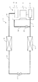
図1に示すように、第1実施形態にかかる冷凍サイクル10は、1つの密閉ハウジング12のキャビティ内に低段側圧縮機構としてのローリングピストン型圧縮機構13と高段側圧縮機構としてのスクロール型圧縮機構15と2つの圧縮機構が収容された多段圧縮機11を有する。この多段圧縮機11の詳細については後述する。
<First Embodiment>
Hereinafter, a first embodiment of the present invention will be described with reference to FIGS. 1 and 2.
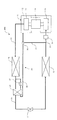
As shown in FIG. 1, the
多段圧縮機11のスクロール型圧縮機構15には、吐出配管19の一端が接続されている。吐出配管19の他端は、第1凝縮器16に接続されている。第1凝縮器16の下流には、冷媒配管20の一端が接続されており、その他端には蒸発器18が接続されている。第1凝縮器16と蒸発器18の間の冷媒配管20上に第1膨張弁17が設けられている。蒸発器18と多段圧縮機11のローリングピストン型圧縮機構13とは、吸入配管21で接続されている。吸入配管21からバイパス配管22が分岐されている。バイパス配管22は、吸入配管21と多段圧縮機11のキャビティとを連通するように設けられている。バイパス配管22には、キャビティへの冷媒の供給を許可又は阻止する第1開閉弁23が設けられている。なお、上流、下流は、冷凍サイクル10の冷媒の流れる向きを基準に特定されるものとする。
One end of a
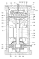
次に、図2に基づいて、多段圧縮機11の構成について説明する。
図1において、密閉ハウジング12内の一方端側にロ−リングピストン型圧縮機構13が、また他方端側にスクロ−ル型圧縮機構15が配設されている。ロ−リングピストン型圧縮機構13とスクロ−ル型圧縮機構15の間には、両者の圧縮機構13,15を駆動する電動モ−タ14が配設されている。
Next, based on FIG. 2, the structure of the
In FIG. 1, a rolling piston
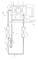
密閉ハウジング12は、上下方向に沿って延びる円筒形に構成されている。密閉ハウジング12の上部には、多段圧縮機11の電動モータ14よりも冷媒流路の下流側のキャビティに開口するバイパス配管22が接続されている。バイパス配管22は吸入配管21から分岐したものであるから、当該キャビティと吸入配管21とが連通される。なお、当該キャビティは、低段側圧縮機構と高段側圧縮機構をともに機能させたときに、中間圧室となる部分である。
また、密閉ハウジング12のキャビティ12a内には、下部側にはロ−リングピストン型圧縮機構13が、上部側にはスクロール型圧縮機構15が収容されている。また、これらロ−リングピストン型圧縮機構13、電動モータ14及びスクロール型圧縮機構15の間には、回転シャフト110が配設されている。この電動モータ14は、密閉ハウジング12の内周部に圧入されて支持されたステ−タ14aと、このステ−タ14aの内側に設けられたロ−タ14bとから構成される。そして、ロ−タ14bは回転シャフト110に同軸上に固定され、その回転が回転シャフト110から出力される。
The
In the
スクロール型圧縮機構15は、全体が鋳鉄や炭素鋼などの鉄系材料で構成された固定スクロ−ル151と、これに噛合う鉄系材料製の旋回スクロ−ル156とを備えている。
The scroll-
固定スクロ−ル151と旋回スクロ−ル156は、ケ−シング状のフレ−ム160上に、固定スクロ−ル151を上側、旋回スクロ−ル156を下側にして配設されている。
旋回スクロール156の端板157の背面は、フレーム160の上面に形成してある水平な受面161にて摺動自在に受け止められている。
The fixed
The rear surface of the
固定スクロ−ル151は、端板152と、端板152の内面に立設された渦巻状のラップ153と、ラップ153を取り囲むように立設した周壁154とを備えている。また、端板152の中央部には吐出ポ−ト155が設けてある。
旋回スクロ−ル156は、端板157と、端板157の内面に立設された渦巻状のラップ158を備えている。端板157の背面(外面)中央部には、筒状のボス部159が突設してある。
そして、固定スクロ−ル151と旋回スクロ−ル156とは、ラップ153,158同士が、180度(所定角度)、ずらして相互に噛み合うように組み合わせられ、上下方向に端板152と端板157とで挟まれたラップ153とラップ158の間に、圧縮工程を成立させるための三日月状の複数個の密閉空間SAが形成される。
The fixed
The
The fixed
回転シャフト110の上端は、フレーム160を貫通して、旋回スクロール156の端板157中央に向かって延びている。この回転シャフト110の上端部は、フレーム160の貫通部分に設けてある軸受162にて回転自在に支持されている。この回転シャフト110の上端には、回転シャフト110の軸心からずれた偏心した位置に偏心ピン163が突設してある。
この偏心ピン163がボス部159に摺動自在に嵌挿されている。こうした偏心ピン163とボス部159との結合で構成される駆動系により、旋回スクロール156は、回転シャフト110が回転すると、固定スクロ−ル151の軸心回りを旋回するようになっている。
The upper end of the
The
また固定スクロ−ル151の周壁154とこれに対向する旋回スクロール156の端板157との間には、旋回スクロール156の旋回運動を許容するが同旋回スクロール156の自転を阻止する自転阻止機構、例えばオルダムリング(図示せず)が介装されている。このオルダムリングおよび偏心ピン163によって得られる旋回スクロール156の旋回公転運動に伴い、密閉空間SAの容積は、次第に減少するようになっている。冷媒ガスは、この密閉空間SAを利用して、圧縮させることができるようになっている。
Further, between the
また固定スクロール151の端板152の上面には、端板152の軸心を中心とした円筒状のフランジ164が上方に向かって突き出ている。フランジ164の上部にはカバ−166が配設されており、フランジ164との間に、吐出キャビティ167が形成される。吐出キャビティ167は、吐出ポート155に連通している。また、密閉ハウジング12の上部壁に接続してある吐出配管19と連通していて、吐出キャビティ167内に吐出された吐出ガスを密閉ハウジング12外へ吐出できるようにしてある。吐出ポ−ト155には、逆流防止用の逆止弁168が設けられている。
A
ローリングピストン型圧縮機構13は、シリンダ130の上下方向の両側にシリンダ130を挟むように主軸受体131および副軸受体132を備えており、シリンダ130に形成されている円形の空間を利用して、主軸受体131および副軸受体132に挟まれる部分にシリンダ室133を形成する。この円形のシリンダ室133内にロータ134およびシリンダ室133を吸込側と吐出側とに仕切るブレ−ド(図示略)が配設されている。そして、ロータ134は、偏心カム部135を介し、電動モータ14の出力軸となる回転シャフト110の一方の端部に連結され、電動モータ14で発生する駆動力によって、ロータ134をシリンダ室133内において偏心回転させるようにしてある。
The rolling
電動モータ14を励磁すると、電動モータ14の回転力が、回転シャフト110を通じて、ローリングピストン型圧縮機構13とスクロール型圧縮機構15とに伝達される。
ローリングピストン型圧縮機構13では、回転シャフト110からの回転力を受けて、ロータ134は、偏心カム部135の偏心動作に従って、シリンダ室133内を偏心回転する。これにより、冷媒ガスは、吸入配管21およびシリンダ室133の吸入ポ−ト136を通して、シリンダ室133内へ吸い込まれ、シリンダ室133で圧縮された後、吐出ポ−ト(図示略)から、一旦、密閉ハウジング12のキャビティ12aに吐出される。ここでの圧縮工程によって、冷媒ガスは低圧から中間圧にまで圧縮される(低段圧縮)。また、このキャビティ12aは、通常、中間圧室と称される。
When the
In the rolling
一方、スクロール型圧縮機構15では、回転シャフト110からの回転力を受けて、偏心ピン163は偏心回転する。これにより、旋回スクロ−ル156は、固定スクロ−ル151に対して公転旋回運動される。すると、ラップ153とラップ158との間に形成される三日月状の密閉空間SAは、容積が小さくなる側に変化する。そのために、キャビティ12a内の冷媒ガスは、フレ−ム160および固定スクロ−ル151の周壁に設けた通路137を通じて、密閉空間SAに吸込まれ、密閉空間SAの容積変化(減)にて圧縮される。
そして、所定の圧縮を終えた冷媒ガスは、固定スクロ−ル151の中央部に設けた吐出ポ−ト155、逆止弁168、吐出キャビティ167、吐出配管19を通じて、密閉ハウジング12外へ吐出されていく。ここでの圧縮工程によって、冷媒ガスは中間圧から高圧にまで圧縮される(高段圧縮)。
On the other hand, in the scroll
The refrigerant gas that has been subjected to the predetermined compression is discharged out of the
次に、冷凍サイクル10の動作について説明する。なお、以下の説明ではバイパス配管22に設けられた第1開閉弁23が閉じられているものとする。
多段圧縮機11のローリングピストン型圧縮機構13には、吸入配管21を介して直接シリンダ室133内に低圧の冷媒ガスが吸入される。この冷媒ガスは、ロータ134が電動モータ14および回転シャフト110を介して回転されることにより、中間圧まで圧縮された後、吐出ポートを経てキャビティ12aに吐出される。これにより、キャビティ12a内は中間圧雰囲気とされる。
Next, the operation of the
Low pressure refrigerant gas is drawn into the
中間圧の冷媒ガスは、密閉ハウジング11内に開口されている通路137を介して高段側のスクロール型圧縮機構15の密閉空間SA内に吸い込まれる。スクロール型圧縮機構15では、電動モータ14の駆動に伴って、旋回スクロール152が固定スクロール151に対して公転旋回駆動されることにより、圧縮作用が行われる。密閉空間SA内で高圧状態まで圧縮された冷媒ガスは、逆止弁168を経て吐出キャビティ167に吐出される。
The intermediate-pressure refrigerant gas is sucked into the sealed space SA of the
吐出キャビティ167内に吐出された高温高圧の冷媒ガスは、吐出キャビティ167に接続されている吐出配管19を経て、図1に実線矢印で示すように、第1凝縮器16に至る。第1凝縮器16で、凝縮器用ファンにより送風される空気と熱交換され、空気側に放熱することにより、冷媒は凝縮液化される。この液冷媒は、冷媒配管20を経て第1膨張弁17により減圧された後、蒸発器18に至る。
The high-temperature and high-pressure refrigerant gas discharged into the
蒸発器18に流入した低圧の気液二相冷媒は、蒸発器18内を流通する間に蒸発器用ファンにより送風される空気と熱交換され、空気側から吸熱することにより蒸発ガス化される。この低圧冷媒ガスは、吸入配管21を介して低段側のローリングピストン型圧縮機構13に吸入され、再び圧縮される。
The low-pressure gas-liquid two-phase refrigerant that has flowed into the
冷凍サイクル10は、以上のサイクルが繰り返される間に、第1凝縮器16からの放熱を利用することにより、暖房または加熱を行うことができ、蒸発器18での吸熱作用を利用することにより、冷房または冷却を行うことができる。
The
多段圧縮機11の負荷が小さい時、すなわち春、秋などの中間期に低い圧力比の下で多段圧縮機11を運転する場合には、スクロール型圧縮機構15及びローリングピストン型圧縮機構13の両方を使うと過大圧縮となり、多大の動力損失を招き、各圧縮機構部の効率を低下させる。そこで、このような場合には、バイパス配管22の第1開閉弁23を開けて、冷媒ガスがローリングピストン型圧縮機構13をバイパスするようにする(バイパス運転)。そうすると、高段側のスクロール型圧縮機構15のみで圧縮が行われ、ローリングピストン型圧縮機構13では圧縮が行われないので、過大圧縮を避けることができる。
多段圧縮機11は、バイパス配管22が、電動モータ14よりも冷媒流路の下流側のキャビティ12aに接続されている。したがって、バイパス配管22から密閉ハウジング12に流入した冷媒ガスは、電動モータ14を通過することがないので、過熱損失、圧力損失を生じることなく、バイパス配管22から供給された冷媒が高段側のスクロール型圧縮機構15に到達する。かくしてスクロール型圧縮機構15の吸入効率を高め、バイパス運転時の多段圧縮機11の性能を向上させることができる。
When the load of the
In the
本発明において、バイパス配管22が電動モータ14よりも冷媒流路の下流側のキャビティ12aに開口していれば、過熱損失、圧力損失を生じることなく高効率な運転を行なえるという効果を得ることができるが、好ましくは、スクロール型圧縮機構15よりも上方に当該開口を設ける。バイパス配管22から供給される冷媒ガスが潤滑油を巻き込むのを避けるためである。
In the present invention, if the
バイパス運転を行うか否かは、例えば以下のようにして特定できる。吸入側の圧力(P1)と吐出側の圧力(P2)とを検知し、その差圧(P2−P1)が予め定められる閾値(Ps)未満であれば、第1開閉弁23を開けて、スクロール型圧縮機構15のみで冷媒を圧縮するバイパス運転を行なう。一方、差圧(P2−P1)が予め定められる閾値(Ps)以上であれば、第1開閉弁23を閉じて、ローリングピストン型圧縮機構13及びスクロール型圧縮機構15で冷媒を圧縮する通常運転を行う。なお、バイパス運転を行なうか否かの判断を、差圧(P2−P1)を用いて判断するのは、あくまで一例である。
Whether or not to perform the bypass operation can be specified as follows, for example. If the pressure (P1) on the suction side and the pressure (P2) on the discharge side are detected and the differential pressure (P2-P1) is less than a predetermined threshold value (Ps), the first on-off
なお、本実施の形態では、低段側にローリングピストン型圧縮機構13、高段側にスクロール型圧縮機構15を用いた例について説明したが、本発明はこれに限定されず、例えば高段側に低段側と同様のローリングピストン型圧縮機構13を用いてもよい。
また、冷凍サイクル10について必要最小限の構成のみを記載したが、多段圧縮機11と第1凝縮器16との間にオイルセパレータを設ける、あるいは多段圧縮機11の吐出配管19と吸入配管21との間に四方切換弁を設けたヒートポンプサイクルとする等の変形例は、いずれも本発明に包含されるものである。
In the present embodiment, an example in which the rolling piston
Moreover, although only the minimum necessary configuration for the
<第2実施形態>…アキュムレータの位置
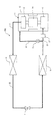
図3を参照して本発明の第2実施形態に係る冷凍サイクル200を説明する。
冷凍サイクル200は、アキュムレータ24を備えていることを除けば、第1実施形態の冷凍サイクル10と同様の構成を有している。したがって、冷凍サイクル10と同様の構成部分については、図1と同じ符号を付して、その説明は省略する。
Second Embodiment Accumulator Position
The
図3に示すように、バイパス配管22は、アキュムレータ24が接続される位置よりも冷媒流路の上流側で吸入配管21から分岐されている。
アキュムレータ24は、蒸発器18から吐出される低圧冷媒ガスを受け、液分(油を含む)を分離する。液分が分離されたガス分のみの冷媒が吸入配管21を介して低段側のローリングピストン型圧縮機構13に吸入さる。ローリングピストン型圧縮機構13は、冷媒を直接吸入するため、液分を除くことが望ましいからである。一方で、アキュムレータ24を通過すると、冷媒には圧力損失が生じる。
バイパス配管22を介して供給される冷媒は、密閉ハウジング12内のキャビティに吸入される。このとき、密閉ハウジング12がアキュムレータとしての機能を発揮し、液分が分離された後に、高段側のスクロール型圧縮機構15で圧縮される。したがって、圧力損失を生じさせないためにも、バイパス配管22には、アキュムレータ24を設けるべきでない。
そこで、第2実施形態では、バイパス配管22は、アキュムレータ24が接続される位置よりも冷媒流路の上流側で吸入配管21から分岐させて、バイパス運転時には、アキュムレータ24を通過させないこととした。
したがって、第2実施形態によれば、バイパス運転時のアキュムレータ24による圧力損失をなくして、多段圧縮機11の運転効率を向上できる。
As shown in FIG. 3, the
The
The refrigerant supplied through the
Therefore, in the second embodiment, the
Therefore, according to 2nd Embodiment, the pressure loss by the
<第3実施形態>…インジェクション管合流
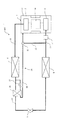
図4を参照して本発明の第3実施形態に係る冷凍サイクル300を説明する。
冷凍サイクル300は、ガスインジェクション回路25を備えていることを除けば、第2実施形態の冷凍サイクル200と同様の構成を有している。したがって、冷凍サイクル200と同様の構成部分については、図3と同じ符号を付して、その説明は省略する。
<Third Embodiment> ... Injection pipe merging A refrigeration cycle 300 according to a third embodiment of the present invention will be described with reference to FIG.
The refrigeration cycle 300 has the same configuration as the
ガスインジェクション回路25は、以下のように構成されている。
第1凝縮器16と第1膨張弁の間の冷媒配管20に、第2凝縮器26が設けられている。また、第2凝縮器26を貫通するインジェクション配管28は、一端が第1凝縮器16と第2凝縮器26との間に接続され、他端がバイパス配管22に合流されている。インジェクション配管28には、第2凝縮器26より上流側に第2膨張弁27が設けられている。また、インジェクション配管28には、第2凝縮器26より下流側に第2開閉弁29が設けられている。
The
A
第1凝縮器16で凝縮液化された液冷媒の一部は、インジェクション配管28を経て第2膨張弁27により減圧された後、第2凝縮器26に至る。第2凝縮器26に流入した低圧の気液二相冷媒は、第2凝縮器26内を流通する間に冷媒配管20を通る液冷媒から吸熱することにより蒸発ガス化され中間圧の冷媒ガスとなる。この冷媒ガスは、インジェクション配管28を経て、密閉ハウジング12のキャビティに供給される。なお、第2開閉弁29は開けられているが、第1開閉弁23は閉じられているものとする。そうすると、この中間圧のインジェクションガスと低段側のローリングピストン型圧縮機構13で圧縮された中間圧ガスとを、高段側のスクロール型圧縮機構15に吸入して、2段圧縮することにより冷凍能力を向上できる。
A part of the liquid refrigerant condensed and liquefied by the
冷凍サイクル300は、インジェクション配管28をバイパス配管22と合流させているので、密閉ハウジング12に直接的に接続される配管の数を1つに減らすことができる。したがって、多段圧縮機11の振動に伴う配管の破損リスクを低減できる。また、多段圧縮機11に対する配管の取り付け作業が容易となり、低コスト化にも寄与する。
また、冷凍サイクル300は、インジェクション配管28をバイパス配管22と合流させているので、ガスインジェクションにより供給される中間圧のガス冷媒も、電動モータ14を通過しない。したがって、このガス冷媒には、圧力損失、過熱損失が生じない。
本発明は、ここで示した方式のガスインジェクションに限らず、他の方式のガスインジェクションについても適用できる。
また、ガスインジェクションに限らず、液インジェクションについても適用できる。
In the refrigeration cycle 300, since the
Further, since the refrigeration cycle 300 joins the
The present invention can be applied not only to the gas injection of the system shown here but also to other types of gas injection.
Moreover, it is applicable not only to gas injection but also to liquid injection.
<第4実施形態>
図5、図6を参照して本発明の第4実施形態に係る冷凍サイクル400を説明する。
冷凍サイクル400は、第2開閉弁29を、バイパス配管22の第1開閉弁23と共通にしたことを除けば、第3実施形態の冷凍サイクル300と同様の構成有している。したがって、冷凍サイクル300と同様の構成部分については、図4と同じ符号を付して、その説明は省略する。
<Fourth embodiment>
A
The
冷凍サイクル400は、バイパス配管22とインジェクション配管28との合流地点に切替え弁30を設けている。切替え弁30は、インジェクション配管28からのガス冷媒が多段圧縮機11のキャビティに供給されるのを許可するが、バイパス配管22からの冷媒ガスが多段圧縮機11の中間圧室に供給されるのを阻止する第1の位置(図5)と、インジェクション配管28からのガス冷媒が多段圧縮機11の中間圧室に供給されるのを阻止するが、バイパス配管22からの冷媒ガスが多段圧縮機11の中間圧室に供給されるのを許可する第2の位置(図6)とに切り替えられる。
In the
一般に、ガスインジェクションを使用するのは、多段圧縮機11の負荷が大きい時であり、この時はバイパス運転を行わなくてもよい。逆に、バイパス運転を行なうのは、多段圧縮機11の負荷が小さい時であり、この時はガスインジェクションを使用しなくてもよい。したがって、冷凍サイクル400のように、バイパス配管22とインジェクション配管28との合流地点に一つの切替え弁30を設けてコスト低減を図りながらも、必要なときにのみガスインジェクションを使用し又はバイパス運転を行うことができる。
In general, the gas injection is used when the load of the
切替え弁30は、吸入側の圧力(P1)と吐出側の圧力(P2)とを検知し、差圧(P2−P1)が予め定められる閾値(Ps)以上であれば、インジェクション配管28からのガス冷媒が多段圧縮機11の中間圧室に供給されるのを許可するが、バイパス配管22からの冷媒ガスが多段圧縮機11の中間圧室に供給されるのを阻止する第1の位置とする。また、差圧(P2−P1)が予め定められる閾値(Ps)未満であれば、インジェクション配管28からのガス冷媒が多段圧縮機11の中間圧室に供給されるのを阻止するが、バイパス配管22からの冷媒ガスが多段圧縮機11の中間圧室に供給されるのを許可する第2の位置とする。
The switching
<第5実施形態>
図7、図8を参照して本発明の第5実施形態に係る冷凍サイクル500を説明する。
第1〜第4実施形態では、バイパス運転は、多段圧縮機11の負荷が小さい時に行なうことを前提としている。第5実施形態による冷凍サイクル500は、これ以外にもバイパス運転を行なうことが多段圧縮機11にとって有益であることを示す。
冷凍サイクル500は、冷凍サイクル400にコントローラ31等の制御系を加えたものである。
コントローラ31は、図示しない主コントローラからの指令信号を受けて、冷凍サイクル500の動作を制御する。
また、冷凍サイクル500は、吸入側の圧力(P1)を検知する圧力センサ32及び吐出側の圧力(P2)を検知する圧力センサ33を備えている。圧力センサ32及び圧力センサ33で検知された圧力(P1)情報及び圧力(P2)情報は、コントローラ31に送られる。コントローラ31は、取得した圧力(P1)情報及び圧力(P2)情報から、両者の差圧(P2−P1)を求める。この差圧に基づいて、コントローラ31は、切換え弁30の動作を制御する。
<Fifth Embodiment>
A
In the first to fourth embodiments, it is assumed that the bypass operation is performed when the load of the
The
The
The
コントローラ31による多段圧縮機11の制御手順を、図8を参照して説明する。
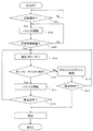
コントローラ31は、主コントローラからの指令信号として多段圧縮機11の起動指示を受信すると(図8 S101)、バイパス運転の位置(図6)になるように切換え弁30を動作させる(図8 S103)。そうすると、バイパス配管22からの冷媒ガスが多段圧縮機11のキャビティに供給されるが、インジェクション配管28からのガス冷媒が多段圧縮機11の中間圧室に供給されるのは阻止される。起動指示後にバイパス運転を行うのは、起動時に多段圧縮機11の圧力変動を小さく抑えるためである。
A control procedure of the
When the
起動指示後のバイパス運転を所定時間行われ(図8 S105)、所定時間経過後に、コントローラ31は、圧力センサ32及び圧力センサ33で検知された圧力(P1)情報及び圧力(P2)情報を取得する。コントローラ31は、取得した圧力(P1)情報及び圧力(P2)情報から、両者の差圧(P2−P1)を算出する(図8 S107)。
The bypass operation after the start instruction is performed for a predetermined time (FIG. 8, S105), and after the predetermined time has elapsed, the
次に、コントローラ31は、得られた差圧(P2−P1)と所定の閾値Psとを比較(図8 S109)する。差圧(P2−P1)が所定の閾値Ps未満であれば、バイパス運転を継続する(図8 S111)。したがって、切換え弁30は、従前のままに制御される。一方、差圧(P2−P1)が所定の閾値Ps以上であれば、ガスインジェクションを使用する(図8 S113)。コントローラ31は、バイパス配管22からの冷媒ガスが多段圧縮機11の中間圧室への供給を阻止するが、インジェクション配管28からのガス冷媒が多段圧縮機11の中間圧室に供給を許可するように、切換え弁30を切り替える。
Next, the
コントローラ31は、バイパス運転、ガスインジェクション適用運転のいずれにおいても、主コントローラから多段圧縮機11の停止命令を受けるまで(図8 S115,S117)、得られた差圧(P2−P1)と所定の閾値Psとを比較し、切換え弁30の動作を制御する。
The
以上説明したように、冷凍サイクル500の多段圧縮機11は、起動時にバイパス運転がなされるので、起動時の圧力変動が抑えられ、多段圧縮機11を安全に運転することができる。また、起動時のバイパス運転の後は、多段圧縮機11の負荷に応じて、バイパス運転及びガスインジェクション使用運転を選択的に行うので、運転効率が高い。
As described above, since the
10,200,300,400,500…冷凍サイクル
11…多段圧縮機
12…密閉ハウジング
13…ローリングピストン型圧縮機構
14…電動モータ
15…スクロール型圧縮機構
16…第1凝縮器
17…第1膨張弁
18…蒸発器
19…吐出配管
20…冷媒配管
21…吸入配管
22…バイパス配管
23,29…開閉弁
24…アキュムレータ
25…ガスインジェクション回路
26…第2凝縮器
27…第2膨張弁
28…インジェクション配管
30…切換え弁
31…コントローラ
DESCRIPTION OF SYMBOLS 10,200,300,400,500 ...
Claims (7)
前記密閉ハウジングのキャビティ内に設けられた低段側圧縮機構及び高段側圧縮機構と、
前記低段側圧縮機構と前記高段側圧縮機構の間に設けられ、前記低段側圧縮機構と前記高段側圧縮機構を駆動する電動モータと、
前記密閉ハウジングに接続され、前記低段側圧縮機構に冷媒を供給する吸入配管と、
前記密閉ハウジングに接続され、前記高段側圧縮機構で圧縮された冷媒を吐出する吐出配管と、
前記吸入配管から分岐され、前記電動モータよりも冷媒流路の下流側の前記キャビティと前記吸入配管とを連通するバイパス配管と、
前記バイパス配管に設けられ、前記キャビティへの冷媒の供給を選択的に許可又は阻止する弁と、
を備えることを特徴とする多段圧縮機。 A sealed housing;
A low-stage compression mechanism and a high-stage compression mechanism provided in the cavity of the sealed housing;
An electric motor provided between the low-stage compression mechanism and the high-stage compression mechanism, and driving the low-stage compression mechanism and the high-stage compression mechanism;
A suction pipe connected to the hermetic housing and supplying a refrigerant to the low-stage compression mechanism;
A discharge pipe that is connected to the hermetic housing and discharges the refrigerant compressed by the high-stage compression mechanism;
A bypass pipe branched from the suction pipe and communicating the cavity and the suction pipe downstream of the refrigerant flow path from the electric motor;
A valve provided in the bypass pipe for selectively permitting or blocking the supply of the refrigerant to the cavity;
A multi-stage compressor comprising:
前記バイパス配管は、前記アキュムレータが接続される位置よりも前記冷媒流路の上流側で前記吸入配管から分岐されることを特徴とする請求項1に記載の多段圧縮機。 An accumulator is provided in the suction pipe;
2. The multistage compressor according to claim 1, wherein the bypass pipe is branched from the suction pipe on the upstream side of the refrigerant flow path with respect to a position where the accumulator is connected.
前記インジェクション配管は、前記バイパス配管と合流することを特徴とする請求項1又は2に記載の多段圧縮機。 An injection pipe is provided for supplying intermediate pressure refrigerant extracted from the refrigerant circuit to the cavity;
The multistage compressor according to claim 1, wherein the injection pipe merges with the bypass pipe.
前記インジェクション配管と前記バイパス配管との合流地点に設けられ、
前記インジェクション配管からの冷媒が前記キャビティに供給されるのを許可するが、前記バイパス配管からの冷媒が前記キャビティに供給されるのを阻止する第1の位置と、
前記インジェクション配管からの冷媒が前記キャビティに供給されるのを阻止するが、前記バイパス配管からの冷媒が前記キャビティに供給されるのを許可する第2の位置とを選択的に切り替えられることを特徴とする請求項3に記載の多段圧縮機。 The valve is
Provided at the junction of the injection pipe and the bypass pipe;
A first position that allows refrigerant from the injection pipe to be supplied to the cavity, but prevents refrigerant from the bypass pipe from being supplied to the cavity;
The second position that prevents the refrigerant from the injection pipe from being supplied to the cavity but allows the refrigerant from the bypass pipe to be supplied to the cavity is selectively switched. The multistage compressor according to claim 3.
前記弁は前記キャビティへの冷媒の供給を許可し、
前記冷媒は前記低段側圧縮機構をバイパスして前記高段側圧縮機構に供給されることを特徴とする請求項1〜3のいずれかに記載の多段圧縮機。 Within a predetermined time when starting the multistage compressor,
The valve permits the supply of refrigerant to the cavity;
The multistage compressor according to any one of claims 1 to 3, wherein the refrigerant is supplied to the high stage compression mechanism by bypassing the low stage compression mechanism.
前記弁は前記第1の位置とされ、
前記冷媒は前記低段側圧縮機構をバイパスして前記高段側圧縮機構に供給されることを特徴とする請求項4に記載の多段圧縮機。 Within a predetermined time when starting the multistage compressor,
The valve is in the first position;
The multi-stage compressor according to claim 4, wherein the refrigerant is supplied to the high-stage compression mechanism by bypassing the low-stage compression mechanism.
前記圧縮機は、
密閉ハウジングと、
前記密閉ハウジングのキャビティ内に設けられた低段側圧縮機構及び高段側圧縮機構と、
前記低段側圧縮機構と前記高段側圧縮機構の間に設けられ、前記低段側圧縮機構と前記高段側圧縮機構を駆動する電動モータと、
前記密閉ハウジングに接続され、前記蒸発器からの冷媒を前記低段側圧縮機構に供給する吸入配管と、
前記密閉ハウジングに接続され、前記高段側圧縮機構で圧縮された冷媒を前記凝縮器に向けて吐出する吐出配管と、
前記吸入配管から分岐され、前記電動モータよりも冷媒流路の下流側の前記キャビティと前記吸入配管とを連通するバイパス配管と、
前記バイパス配管に設けられ、前記キャビティへの冷媒の供給を選択的に許可又は阻止する弁と、
を備える多段圧縮機であることを特徴とする冷凍サイクル。 In a refrigeration cycle in which a compressor, a condenser, an expansion valve, and an evaporator are sequentially connected to form a refrigerant circuit.
The compressor is
A sealed housing;
A low-stage compression mechanism and a high-stage compression mechanism provided in the cavity of the sealed housing;
An electric motor provided between the low-stage compression mechanism and the high-stage compression mechanism, and driving the low-stage compression mechanism and the high-stage compression mechanism;
A suction pipe connected to the hermetic housing and supplying refrigerant from the evaporator to the low-stage compression mechanism;
A discharge pipe connected to the hermetic housing and for discharging the refrigerant compressed by the high-stage compression mechanism toward the condenser;
A bypass pipe branched from the suction pipe and communicating the cavity and the suction pipe downstream of the refrigerant flow path from the electric motor;
A valve provided in the bypass pipe for selectively permitting or blocking the supply of the refrigerant to the cavity;
A refrigeration cycle characterized by being a multistage compressor.
Priority Applications (3)
| Application Number | Priority Date | Filing Date | Title |
|---|---|---|---|
| JP2008229561A JP5330776B2 (en) | 2008-09-08 | 2008-09-08 | Multistage compressor |
| PCT/JP2009/004416 WO2010026776A1 (en) | 2008-09-08 | 2009-09-07 | Multiple-stage compressor |
| EP09811306.1A EP2322804B1 (en) | 2008-09-08 | 2009-09-07 | Multiple-stage compressor |
Applications Claiming Priority (1)
| Application Number | Priority Date | Filing Date | Title |
|---|---|---|---|
| JP2008229561A JP5330776B2 (en) | 2008-09-08 | 2008-09-08 | Multistage compressor |
Publications (2)
| Publication Number | Publication Date |
|---|---|
| JP2010059944A true JP2010059944A (en) | 2010-03-18 |
| JP5330776B2 JP5330776B2 (en) | 2013-10-30 |
Family
ID=41796955
Family Applications (1)
| Application Number | Title | Priority Date | Filing Date |
|---|---|---|---|
| JP2008229561A Active JP5330776B2 (en) | 2008-09-08 | 2008-09-08 | Multistage compressor |
Country Status (3)
| Country | Link |
|---|---|
| EP (1) | EP2322804B1 (en) |
| JP (1) | JP5330776B2 (en) |
| WO (1) | WO2010026776A1 (en) |
Cited By (1)
| Publication number | Priority date | Publication date | Assignee | Title |
|---|---|---|---|---|
| JP2013040583A (en) * | 2011-08-17 | 2013-02-28 | Mitsubishi Heavy Ind Ltd | Two-stage compressor |
Families Citing this family (1)
| Publication number | Priority date | Publication date | Assignee | Title |
|---|---|---|---|---|
| CN105332888A (en) * | 2014-07-22 | 2016-02-17 | 珠海格力节能环保制冷技术研究中心有限公司 | Compressor and air conditioner with same |
Citations (3)
| Publication number | Priority date | Publication date | Assignee | Title |
|---|---|---|---|---|
| JPH0587074A (en) * | 1991-07-30 | 1993-04-06 | Mitsubishi Heavy Ind Ltd | Two stage compressor |
| JP2004218536A (en) * | 2003-01-15 | 2004-08-05 | Mitsubishi Heavy Ind Ltd | Electric compressor |
| JP2008190377A (en) * | 2007-02-02 | 2008-08-21 | Mitsubishi Heavy Ind Ltd | Multistage compressor |
Family Cites Families (5)
| Publication number | Priority date | Publication date | Assignee | Title |
|---|---|---|---|---|
| JP2803456B2 (en) * | 1991-10-23 | 1998-09-24 | 三菱電機株式会社 | Multi-cylinder rotary compressor |
| JPH0683984U (en) * | 1993-05-07 | 1994-12-02 | 三菱重工業株式会社 | Two-stage compressor and two-stage compressor |
| JP3370026B2 (en) * | 1999-09-09 | 2003-01-27 | 三洋電機株式会社 | 2-stage compression type rotary compressor |
| JP4343627B2 (en) * | 2003-03-18 | 2009-10-14 | 東芝キヤリア株式会社 | Rotary hermetic compressor and refrigeration cycle apparatus |
| JP4949817B2 (en) * | 2006-12-08 | 2012-06-13 | 三菱重工業株式会社 | Multistage compressor and refrigeration cycle using the same |
-
2008
- 2008-09-08 JP JP2008229561A patent/JP5330776B2/en active Active
-
2009
- 2009-09-07 EP EP09811306.1A patent/EP2322804B1/en active Active
- 2009-09-07 WO PCT/JP2009/004416 patent/WO2010026776A1/en active Application Filing
Patent Citations (3)
| Publication number | Priority date | Publication date | Assignee | Title |
|---|---|---|---|---|
| JPH0587074A (en) * | 1991-07-30 | 1993-04-06 | Mitsubishi Heavy Ind Ltd | Two stage compressor |
| JP2004218536A (en) * | 2003-01-15 | 2004-08-05 | Mitsubishi Heavy Ind Ltd | Electric compressor |
| JP2008190377A (en) * | 2007-02-02 | 2008-08-21 | Mitsubishi Heavy Ind Ltd | Multistage compressor |
Cited By (1)
| Publication number | Priority date | Publication date | Assignee | Title |
|---|---|---|---|---|
| JP2013040583A (en) * | 2011-08-17 | 2013-02-28 | Mitsubishi Heavy Ind Ltd | Two-stage compressor |
Also Published As
| Publication number | Publication date |
|---|---|
| EP2322804B1 (en) | 2018-08-15 |
| EP2322804A4 (en) | 2016-09-28 |
| JP5330776B2 (en) | 2013-10-30 |
| WO2010026776A1 (en) | 2010-03-11 |
| EP2322804A1 (en) | 2011-05-18 |
Similar Documents
| Publication | Publication Date | Title |
|---|---|---|
| JP4859694B2 (en) | Multistage compressor | |
| US10378539B2 (en) | System including high-side and low-side compressors | |
| WO2011055444A1 (en) | Heat pump device, two-stage compressor, and method of operating heat pump device | |
| WO2006013959A1 (en) | Displacement type expansion machine and fluid machine | |
| JP2004190559A (en) | Displacement expander and fluid machine | |
| JP2000087892A (en) | Two-stage compressor and air conditioner | |
| GB2572870A (en) | Multi-stage scroll compressor | |
| KR100725893B1 (en) | Scroll-type fluid machine | |
| JP2015086704A (en) | Scroll compressor | |
| WO2005010370A1 (en) | Freezer device | |
| JP5330776B2 (en) | Multistage compressor | |
| JP2010150926A (en) | Scroll expander and refrigerating/air-conditioning device including the same | |
| JP3584781B2 (en) | Scroll compressor and refrigerating device | |
| JP7025227B2 (en) | Refrigeration equipment | |
| US20110100025A1 (en) | Fluid machine and refrigeration cycle apparatus | |
| JP2012093017A (en) | Refrigerating cycle device | |
| JP4278402B2 (en) | Refrigerant cycle equipment | |
| JP4222857B2 (en) | Refrigeration equipment | |
| KR101328229B1 (en) | Rotary compressor | |
| JP2005048654A (en) | Compressor | |
| EP2587188A1 (en) | Refrigeration cycle apparatus | |
| WO2022230314A1 (en) | Scroll compressor | |
| KR100677527B1 (en) | Rotary compressor | |
| JP5484604B2 (en) | Refrigeration air conditioner | |
| JP2012098000A (en) | Refrigeration cycle apparatus |
Legal Events
| Date | Code | Title | Description |
|---|---|---|---|
| A621 | Written request for application examination |
Free format text: JAPANESE INTERMEDIATE CODE: A621 Effective date: 20110608 |
|
| A131 | Notification of reasons for refusal |
Free format text: JAPANESE INTERMEDIATE CODE: A131 Effective date: 20130116 |
|
| A521 | Written amendment |
Free format text: JAPANESE INTERMEDIATE CODE: A523 Effective date: 20130208 |
|
| TRDD | Decision of grant or rejection written | ||
| A01 | Written decision to grant a patent or to grant a registration (utility model) |
Free format text: JAPANESE INTERMEDIATE CODE: A01 Effective date: 20130703 |
|
| A61 | First payment of annual fees (during grant procedure) |
Free format text: JAPANESE INTERMEDIATE CODE: A61 Effective date: 20130726 |
|
| R151 | Written notification of patent or utility model registration |
Ref document number: 5330776 Country of ref document: JP Free format text: JAPANESE INTERMEDIATE CODE: R151 |
|
| R250 | Receipt of annual fees |
Free format text: JAPANESE INTERMEDIATE CODE: R250 |
|
| S111 | Request for change of ownership or part of ownership |
Free format text: JAPANESE INTERMEDIATE CODE: R313111 |
|
| R350 | Written notification of registration of transfer |
Free format text: JAPANESE INTERMEDIATE CODE: R350 |