JP2010059922A - Egr device of internal combustion engine - Google Patents
Egr device of internal combustion engine Download PDFInfo
- Publication number
- JP2010059922A JP2010059922A JP2008228897A JP2008228897A JP2010059922A JP 2010059922 A JP2010059922 A JP 2010059922A JP 2008228897 A JP2008228897 A JP 2008228897A JP 2008228897 A JP2008228897 A JP 2008228897A JP 2010059922 A JP2010059922 A JP 2010059922A
- Authority
- JP
- Japan
- Prior art keywords
- egr
- bank
- valve
- passage
- individual
- Prior art date
- Legal status (The legal status is an assumption and is not a legal conclusion. Google has not performed a legal analysis and makes no representation as to the accuracy of the status listed.)
- Granted
Links
Images


Classifications
-
- Y—GENERAL TAGGING OF NEW TECHNOLOGICAL DEVELOPMENTS; GENERAL TAGGING OF CROSS-SECTIONAL TECHNOLOGIES SPANNING OVER SEVERAL SECTIONS OF THE IPC; TECHNICAL SUBJECTS COVERED BY FORMER USPC CROSS-REFERENCE ART COLLECTIONS [XRACs] AND DIGESTS
- Y02—TECHNOLOGIES OR APPLICATIONS FOR MITIGATION OR ADAPTATION AGAINST CLIMATE CHANGE
- Y02T—CLIMATE CHANGE MITIGATION TECHNOLOGIES RELATED TO TRANSPORTATION
- Y02T10/00—Road transport of goods or passengers
- Y02T10/10—Internal combustion engine [ICE] based vehicles
- Y02T10/12—Improving ICE efficiencies
Abstract
Description
本発明は、内燃機関のEGR装置に関する。 The present invention relates to an EGR device for an internal combustion engine.
内燃機関の排気通路と吸気通路とをEGR通路によって接続し、内燃機関からの排気の一部をEGR通路を介してEGRガスとして吸気通路に流入させる技術が知られている。 A technique is known in which an exhaust passage and an intake passage of an internal combustion engine are connected by an EGR passage, and a part of the exhaust from the internal combustion engine flows into the intake passage as EGR gas through the EGR passage.
EGRガス量の調節は、EGR通路に設けたEGR弁の開度を調節することによって行うことができるが、EGR弁が固着した場合にはEGRガス量の調節ができなくなる。 The EGR gas amount can be adjusted by adjusting the opening degree of the EGR valve provided in the EGR passage. However, when the EGR valve is fixed, the EGR gas amount cannot be adjusted.
特に開弁状態でEGR弁が固着した場合、EGRガス量が過多となり、失火等の燃焼不良やトルク不足等の問題が生じる可能性がある。 In particular, when the EGR valve is stuck in the open state, the amount of EGR gas becomes excessive, and there is a possibility that problems such as combustion failure such as misfire and insufficient torque may occur.
これに対し、EGR弁が開弁状態で固着した場合には、内燃機関を減筒運転し且つ吸入空気量を増量することにより、一気筒当たりのEGR率を低下させ、燃焼を安定化させる技術が提案されている(特許文献1を参照)。
しかしながら、開弁状態で固着したEGR弁の開度が大きい場合には、EGRガス量が過多になることを十分に抑制できなかったり、減筒運転によって退避走行のための十分なトルクが得られなかったりする虞があった。 However, when the opening degree of the EGR valve stuck in the valve open state is large, it is not possible to sufficiently suppress an excessive amount of EGR gas, or sufficient torque for evacuation traveling can be obtained by reduced-cylinder operation. There was a risk of not.
本発明はこのような事情に鑑みてなされたものであり、EGR通路に設けられたEGR弁が開固着した場合においても、EGRガス量が過多になることを抑制するとともに、退避走行のための十分なトルクを確保することを可能にする技術を提供することを目的とする。 The present invention has been made in view of such circumstances, and even when the EGR valve provided in the EGR passage is stuck open, it is possible to suppress an excessive amount of EGR gas and to perform retreat traveling. An object of the present invention is to provide a technique that makes it possible to ensure a sufficient torque.
上記目的を達成するため、本発明の内燃機関のEGR装置は、
複数のバンクを有する内燃機関と、
前記複数のバンクのうちの一部のバンクである所定のEGR取り出し有りバンクからの排気の少なくとも一部を取り出してEGRガスとして前記内燃機関の吸気通路に流入させる一又は複数のEGR通路と、
前記各EGR通路に設けられたEGR弁と、
前記各EGR取り出し有りバンクへ流入する吸気量を制御する吸気量制御手段と、
前記各EGR弁の開固着を検知する故障検知手段と、
前記故障検知手段によって前記EGR弁の開固着が検知された場合に、前記EGR取り出し有りバンクのうち、当該開固着したEGR弁が設けられたEGR通路によってその排気の一部がEGRガスとして取り出されるように構成されているEGR取り出し有りバンクの吸気量を、EGR弁が開固着していない通常時よりも減少させる故障時制御手段と、を備えることを特徴とする。
In order to achieve the above object, an EGR device for an internal combustion engine of the present invention comprises:
An internal combustion engine having a plurality of banks;
One or a plurality of EGR passages that take out at least a part of the exhaust from a bank with a predetermined EGR take-out that is a part of the plurality of banks and flow into the intake passage of the internal combustion engine as EGR gas;
An EGR valve provided in each EGR passage;
An intake air amount control means for controlling an intake air amount flowing into the bank with each EGR take-out,
A failure detection means for detecting open adhesion of each EGR valve;
When the failure detection means detects that the EGR valve is stuck open, a part of the exhaust gas is taken out as EGR gas by the EGR passage provided with the opened EGR valve in the EGR take-out bank. And a failure-time control means for reducing the intake air amount of the EGR take-out bank configured as described above from the normal time when the EGR valve is not open and fixed.
EGR弁が開固着すると、当該開固着したEGR弁が設けられたEGR通路の流路面積
が通常時よりも広くなる。そのため、通常時と同量の排気が排気通路から当該EGR通路に流入した場合、通常時よりも多い量のEGRガスが当該EGR通路を介して吸気通路に流入し得る。
When the EGR valve is open and fixed, the flow area of the EGR passage provided with the open and fixed EGR valve becomes larger than usual. Therefore, when the same amount of exhaust gas as normal flows into the EGR passage from the exhaust passage, a larger amount of EGR gas than normal can flow into the intake passage through the EGR passage.
この意味で、以下、開固着したEGR弁が設けられたEGR通路によってその排気の一部がEGRガスとして取り出されるように構成されているEGR取り出し有りバンクを「EGR取り出し増大バンク」と称する。 In this sense, hereinafter, an EGR take-out bank configured such that a part of the exhaust gas is taken out as EGR gas by the EGR passage provided with the open and fixed EGR valve is referred to as an “EGR take-out increase bank”.
上記本発明によれば、EGR弁の開固着した検知された場合、EGR取り出し増大バンクへ流入する吸気量が通常時よりも減少させられるので、EGR取り出し増大バンクから排出される排気量が減少する。 According to the present invention, when it is detected that the EGR valve is open and stuck, the amount of intake air flowing into the EGR take-out increase bank is reduced as compared with the normal time, so the amount of exhaust discharged from the EGR take-out increase bank is reduced. .
従って、開固着したEGR弁が設けられたEGR通路には、通常時よりも少ない量の排気しか流入しない。 Accordingly, only a smaller amount of exhaust gas flows into the EGR passage provided with the open-fixed EGR valve than usual.
そのため、開固着したEGR弁が設けられたEGR通路が、EGR弁の開固着により、通常時よりも多い量のEGRガスが流通し得る状態になっている場合であっても、実際に当該EGR通路を経由して吸気通路に流入するEGRガスの量が通常時よりも過多にならないようにすることができる。 Therefore, even if the EGR passage provided with the open-fixed EGR valve is in a state where a larger amount of EGR gas than normal can flow due to the open-fixation of the EGR valve, the EGR valve actually It is possible to prevent the amount of EGR gas flowing into the intake passage via the passage from being excessive as compared with the normal time.
これにより、EGR弁が開固着した場合においても、燃焼不良やトルク不足等の問題が生じることを抑制することが可能となる。 Thereby, even when the EGR valve is stuck open, it is possible to suppress the occurrence of problems such as poor combustion and insufficient torque.
ここで、EGR弁の開固着によって吸気通路に流入するEGRガス量が過多になる場合としては、当該開固着したEGR弁の開度が、内燃機関の運転条件に応じて定まる目標EGR弁開度よりも、開き側の開度である場合を例示できる。 Here, when the amount of EGR gas flowing into the intake passage becomes excessive due to the open fixing of the EGR valve, the opening degree of the open and fixed EGR valve is determined according to the operating condition of the internal combustion engine. As an example, the opening degree on the open side can be exemplified.
逆に、EGR弁が開弁状態で固着した場合であっても、当該固着したEGR弁の開度が目標EGR弁開度以下であれば、EGRガス量が過多にはなりにくい。 Conversely, even if the EGR valve is stuck in the open state, the amount of EGR gas is unlikely to be excessive if the degree of opening of the stuck EGR valve is equal to or less than the target EGR valve opening.
従って、本発明の故障時制御手段は、EGR弁の固着を検知した場合、当該開固着したEGR弁の開度が目標EGR弁開度よりも開き側の開度であるような運転条件下に限って、上述したEGR取り出し増大バンクの吸気量の減量制御を行うようにしても良い。 Therefore, the failure time control means of the present invention, when detecting the sticking of the EGR valve, operates under such operating conditions that the opening degree of the open and stuck EGR valve is the opening degree on the opening side with respect to the target EGR valve opening degree. For example, the above-described EGR extraction increase bank intake air amount reduction control may be performed.
なお、本発明において、故障時制御手段は、EGR弁開固着時に、全てのEGR取り出し増大バンクの吸気量を減少させるようにすれば、EGR弁開固着時のEGRガス量過多を好適に抑制し、燃焼不良やトルク不足の問題をより確実に抑制できるが、少なくとも一つのEGR取り出し増大バンクの吸気量を減少させるのでも、EGR弁開固着時にEGRガス量が過多になることを抑制し、燃焼不良やトルク不足の問題を軽減させる効果を奏する。 In the present invention, if the failure time control means reduces the intake air amount of all EGR take-out increase banks when the EGR valve is stuck open, the excessive amount of EGR gas when the EGR valve is stuck open is preferably suppressed. , The problem of combustion failure and torque shortage can be more reliably suppressed, but even if the intake air amount of at least one EGR take-out increase bank is reduced, the EGR gas amount is suppressed from being excessive when the EGR valve is stuck open, and combustion This has the effect of reducing the problems of defects and insufficient torque.
また、故障時制御手段は、EGR弁開固着時に、全てのEGR取り出し有りバンクの吸気量を減少させるようにしても良い。この場合、EGR弁が開固着していないEGR通路によって排気の一部がEGRガスとして取り出されるように構成されているEGR取り出し有りバンクについても吸気量が減量される場合が考えられるが、少なくとも、EGRガス量が過多になることに起因する燃焼不良やトルク不足の問題を回避することが可能となる。 Further, the failure time control means may reduce the intake air amount of all EGR removal banks when the EGR valve is stuck open. In this case, it is conceivable that the intake air amount is also reduced in the bank with EGR extraction configured such that a part of the exhaust gas is extracted as EGR gas by the EGR passage where the EGR valve is not open and fixed, It becomes possible to avoid the problem of poor combustion and insufficient torque due to an excessive amount of EGR gas.
また、本発明において、吸気量制御手段は、各EGR取り出し有りバンクの吸気量を個別に制御可能な手段であっても良いし、複数のEGR取り出し有りバンクの吸気量を一律
に制御する手段であっても良い。
Further, in the present invention, the intake air amount control means may be means capable of individually controlling the intake air amount of each bank with EGR extraction, or means for uniformly controlling the intake air amounts of a plurality of banks with EGR extraction. There may be.
前者の場合には、本発明の故障時制御手段は、EGR弁の開固着が検知された場合に、EGR取り出し有りバンクのうち、EGR取り出し増大バンクではないバンクについては吸気量減量制御の対象としないようにしても良い。 In the former case, the failure time control means of the present invention, when it is detected that the EGR valve is stuck open, out of the banks with EGR extraction, the banks that are not EGR extraction increase banks are subject to intake air amount reduction control. You may not make it.
こうすることで、EGR弁が正常動作してEGRガス量を目標値通りに制御可能なEGR取り出し有りバンクについては、吸気量減量制御の対象とならないので、EGR弁の開固着検知時のEGRガス量制御をより精度良く行うことができる。 By doing this, an EGR take-out bank in which the EGR valve operates normally and the EGR gas amount can be controlled according to the target value is not subject to intake air amount reduction control. Therefore, the EGR gas at the time of detecting the EGR valve open sticking is detected. Quantity control can be performed with higher accuracy.
なお、EGR取り出し増大バンクではないバンクについても、EGR取り出し増大バンクと同様に吸気量減量制御の対象としても良い。 Note that banks that are not EGR take-out increase banks may be subject to intake air amount reduction control as in the case of EGR take-out increase banks.
後者の場合には、本発明の故障時制御手段は、EGR弁の開固着が検知された場合に、EGR取り出し有りバンクの吸気量を一律に減量する。 In the latter case, the failure-time control means of the present invention uniformly reduces the intake air amount of the bank with the EGR take-out when it is detected that the EGR valve is stuck open.
本発明において、EGR通路が複数系統備えられ、さらにEGR弁が複数個備えられた構成の場合、故障検知手段は、各EGR弁の開固着を個別に検知するものであっても良いし、複数個のEGR弁のうちに開固着したものが存在することを検知するものであっても良い。 In the present invention, when a plurality of EGR passages are provided and a plurality of EGR valves are provided, the failure detection means may detect open adhesion of each EGR valve individually. It may be detected that there is an open and fixed one of the EGR valves.
前者の場合、開固着したEGR弁を特定することができるので、故障時制御手段による吸気量減量制御の対象をEGR取り出し増大バンクに限定する制御が可能である。 In the former case, since the open EGR valve can be specified, it is possible to control the target of the intake air amount decrease control by the failure time control means to the EGR take-out increase bank.
後者の場合、少なくとも一つのEGR弁が開固着した場合に、故障制御手段による吸気量減量制御が行われるので、より確実にEGRガス量過多に起因する問題の発生を抑制できる。 In the latter case, when at least one EGR valve is fixed open, the intake air amount reduction control is performed by the failure control means, so that it is possible to more reliably suppress the occurrence of problems due to excessive EGR gas amount.
本発明において、前記故障時制御手段は、前記開固着したEGR弁の開度が開き側の開度であるほど、EGR取り出し増大バンクの吸気量を、より減少させるようにしても良い。 In the present invention, the failure-time control means may further reduce the intake air amount of the EGR take-out increase bank as the opening degree of the open and fixed EGR valve is the opening side.
こうすることで、EGR取り出し増大バンクから排出される排気の量がより一層少なくなるので、EGR弁が例えば全開状態のような大きな開度の状態で開固着したような場合においても、EGRガス量が過多になることをより確実に抑制することが可能となる。 By doing so, the amount of exhaust gas discharged from the EGR take-out increase bank is further reduced. Therefore, even when the EGR valve is opened and fixed in a large opening state such as a fully opened state, the amount of EGR gas is increased. It becomes possible to more reliably suppress the excess of.
本発明において、EGR弁の開固着検知時に、EGR取り出し増大バンクの吸気量を減少させる具体的な手段としては、
前記各EGR取り出し有りバンクに個別に接続された個別吸気通路を更に備え、
前記吸気量制御手段は、前記各個別吸気通路に設けられた個別スロットル弁を有し、
前記故障時制御手段は、前記故障検知手段によって前記EGR弁の開固着が検知された場合に、EGR取り出し増大バンクに接続された個別吸気通路に設けられた前記個別スロットル弁の開度を、EGR弁が固着していない通常時よりも閉じ側の開度にするようにしても良い。
In the present invention, as a specific means for reducing the intake amount of the EGR take-out increase bank at the time of detecting the open adhesion of the EGR valve,
Further comprising individual intake passages individually connected to the EGR take-out banks,
The intake air amount control means has an individual throttle valve provided in each individual intake passage,
When the failure detecting means detects that the EGR valve is stuck open, the failure time control means determines the opening degree of the individual throttle valve provided in the individual intake passage connected to the EGR take-out increase bank. You may make it make it the opening degree of a close side rather than the normal time when the valve has not adhered.
このように、EGR取り出し増大バンクの個別吸気通路に設けられた個別スロットル弁を絞ることにより、EGR取り出し増大バンクの吸気量を減少させることができるので、EGR弁が開固着した場合においても、EGRガス量が過多になることを抑制できる。 In this way, by reducing the individual throttle valve provided in the individual intake passage of the EGR take-out increase bank, the intake amount of the EGR take-out increase bank can be reduced. Therefore, even when the EGR valve is fixed open, EGR An excessive gas amount can be suppressed.
また、上記構成によれば、各EGR取り出し有りバンクの個別スロットル弁開度を独立
に制御することができるので、上記のように構成された吸気量制御手段は、EGR取り出し有りバンクの吸気量を個別に制御することが可能である。
Further, according to the above configuration, since the individual throttle valve opening degree of each EGR take-out bank can be controlled independently, the intake air amount control means configured as described above can control the intake air amount in the EGR take-out bank. It can be controlled individually.
従って、EGR弁の開固着が検知された場合に、特にEGR取り出し増大バンクについてのみ吸気量を減量するように制御することも可能である。 Therefore, it is also possible to perform control so that the intake air amount is decreased only when the EGR valve is stuck open, particularly for the EGR take-out increase bank.
このように、EGR取り出し増大バンクの吸気量を、EGR取り出し増大バンクの個別吸気通路に設けられた個別スロットル弁を閉じ側にすることによって減少させるようにする場合、開固着したEGR弁の開度が開き側の開度であるほど、EGR取り出し増大バンクの個別吸気通路に設けられた個別スロットル弁をより閉じ側の開度にするようにしても良い。 As described above, when the intake amount of the EGR take-out increase bank is decreased by closing the individual throttle valve provided in the individual intake passage of the EGR take-out increase bank, the opening degree of the open EGR valve is fixed. The more the opening is on the opening side, the more the individual throttle valve provided in the individual intake passage of the EGR extraction increasing bank may be set to the opening on the more closed side.
こうすることで、EGR取り出し増大バンクの吸気量をより一層減少させることができる。 In this way, the intake air amount of the EGR take-out increase bank can be further reduced.
本発明において、EGR弁の開固着検知時に、EGR取り出し増大バンクの吸気量を減少させる具体的な手段としては、
前記吸気量制御手段は、前記各EGR取り出し有りバンクの気筒の吸気バルブタイミングを可変制御可能な吸気VVT機構を有し、
前記故障時制御手段は、前記故障検知手段によって前記EGR弁の開固着が検知された場合に、EGR取り出し増大バンクの気筒の吸気バルブの閉弁時期を、EGR弁が固着していない通常時よりも遅角させるようにしても良い。
In the present invention, as a specific means for reducing the intake amount of the EGR take-out increase bank at the time of detecting the open adhesion of the EGR valve,
The intake air amount control means has an intake VVT mechanism capable of variably controlling the intake valve timing of the cylinders in the bank with each EGR take-out,
When the failure detecting means detects that the EGR valve is stuck open, the failure time control means sets the closing timing of the intake valve of the cylinder of the EGR take-out increase bank from the normal time when the EGR valve is not stuck. May be retarded.
このように、吸気VVT機構により、EGR取り出し増大バンクの気筒の吸気バルブの閉弁時期を遅角させることで、EGR取り出し増大バンクの吸気量を減少させることができるので、EGR弁が開固着した場合においても、EGRガス量が過多になることを抑制できる。 As described above, the intake air amount of the EGR take-out increase bank can be reduced by delaying the valve closing timing of the intake valve of the cylinder of the EGR take-out increase bank by the intake VVT mechanism, so that the EGR valve is stuck open. Even in the case, it is possible to suppress an excessive amount of EGR gas.
また、上記構成によれば、各EGR取り出し有りバンクの吸気バルブタイミングを個別に可変制御することができるので、上記のように構成された吸気量制御手段は、EGR取り出し有りバンクの吸気量を個別に制御することが可能である。 Further, according to the above configuration, the intake valve timing of each EGR take-out bank can be variably controlled. Therefore, the intake air amount control means configured as described above individually sets the intake air amount in the EGR take-out bank. It is possible to control.
従って、EGR弁の開固着が検知された場合に、特にEGR取り出し増大バンクについてのみ吸気量を減量するように制御することも可能である。 Therefore, it is also possible to perform control so that the intake air amount is decreased only when the EGR valve is stuck open, particularly for the EGR take-out increase bank.
このように、EGR取り出し増大バンクの吸気量を、EGR取り出し増大バンクの吸気バルブの閉弁時期を遅角させることによって減少させるようにする場合、開固着したEGR弁の開度が開き側の開度であるほど、EGR取り出し増大バンクの吸気バルブの閉弁時期をより遅角させるようにしても良い。 As described above, when the intake amount of the EGR take-out increase bank is decreased by delaying the closing timing of the intake valve of the EGR take-out increase bank, the opening degree of the open EGR valve is set to open on the open side. As the degree increases, the closing timing of the intake valve of the EGR take-out increase bank may be delayed more.
こうすることで、EGR取り出し増大バンクの吸気量をより一層減少させることができる。 In this way, the intake air amount of the EGR take-out increase bank can be further reduced.
また、このように各EGR取り出し有りバンクの気筒の吸気バルブタイミングをバンク毎に個別に可変制御可能な吸気VVT機構を備えた構成とした場合には、各バンクの吸気量を個別に制御可能な個別スロットル弁を設ける必要がないので、スロットル弁として共有吸気通路に設けた単一のスロットル弁のみを備えた簡易な構成とすることもできる。 In addition, when the intake valve timing of the cylinders in each EGR take-out bank is thus variably controlled for each bank, the intake amount in each bank can be individually controlled. Since there is no need to provide an individual throttle valve, a simple configuration including only a single throttle valve provided in the common intake passage as a throttle valve can be provided.
以上説明したように、本発明では、EGR弁の開固着を検知した時に、EGR取り出し増大バンクの吸気量を減少させる。これにより、上述したように、EGRガス量が過多に
なることを抑制でき、燃焼不良が生じることを抑制できる。
As described above, in the present invention, the intake amount of the EGR take-out increase bank is decreased when the open adhesion of the EGR valve is detected. Thereby, as above-mentioned, it can suppress that EGR gas amount becomes excessive, and can suppress that a combustion failure arises.
一方、この場合、EGR取り出し増大バンクのトルクは吸気量の減少に応じて低下するため、トルク不足が生じる可能性がある。トルク低下の度合が大きい場合、退避走行のためのトルクが安定して得られなくなる虞もある。 On the other hand, in this case, since the torque of the EGR take-out increase bank decreases as the intake air amount decreases, a torque shortage may occur. When the degree of torque reduction is large, there is a possibility that torque for evacuation traveling cannot be obtained stably.
そこで、本発明において、
前記各EGR通路のいずれによってもその排気の一部がEGRガスとして取り出されないバンクであるEGR取り出し無しバンクへ流入する吸気量を制御する第2吸気量制御手段と、
前記故障検知手段によって前記EGR弁の開固着が検知された場合に、前記EGR取り出し無しバンクの吸気量を、EGR弁が開固着していない通常時よりも増加させる第2故障時制御手段と、
を更に備えるようにしても良い。
Therefore, in the present invention,
A second intake air amount control means for controlling an intake air amount flowing into a bank without EGR removal, which is a bank where a part of the exhaust gas is not taken out as EGR gas by any of the EGR passages;
A second failure time control means for increasing an intake air amount of the bank without EGR removal when compared to a normal time when the EGR valve is not openly fixed when the failure detection means detects that the EGR valve is stuck open;
May be further provided.
EGR取り出し無しバンクの吸気量が増加させられことにより、EGR取り出し無しバンクの気筒の燃焼により発生するトルクが大きくなる。従って、EGR弁が開固着した場合のトルク不足を抑制することが可能となる。 By increasing the intake air amount in the bank without EGR removal, the torque generated by the combustion of the cylinders in the bank without EGR removal increases. Therefore, it is possible to suppress torque shortage when the EGR valve is stuck open.
しかも、EGR取り出し無しバンクから排出される排気からはEGRガスは取り出されないので、EGR弁が開固着している場合にEGR取り出し無しバンクの吸気量を増加させても、EGRガス量が過多になる虞はない。 Moreover, since the EGR gas is not extracted from the exhaust gas discharged from the bank without EGR removal, even if the intake air amount of the bank without EGR removal is increased when the EGR valve is fixed open, the amount of EGR gas is excessive. There is no fear of becoming.
上記構成において、前記第2故障時制御手段は、前記開固着したEGR弁の開度が開き側の開度であるほど、前記EGR取り出し無しバンクの吸気量を、より増加させるようにしても良い。 In the above configuration, the second failure time control means may increase the intake air amount of the bank without EGR removal as the opening degree of the open and fixed EGR valve is an opening degree. .
上述したように、本発明においては、開固着したEGR弁の開度が開き側の開度であるほど、EGR取り出し増大バンクの吸気量をより一層減少させる制御を行うことができるが、その場合、トルク不足もより起こり易くなる。 As described above, in the present invention, as the opening degree of the open EGR valve is the opening side, the control can be performed to further reduce the intake amount of the EGR take-out increase bank. Insufficient torque is more likely to occur.
この点、上記構成のようにすれば、開固着したEGR弁の開度が開き側の開度であるほどEGR取り出し無しバンクの吸気量が一層多くなるので、トルク不足をより確実に抑制することが可能となる。 In this regard, according to the above configuration, the amount of intake air in the bank without EGR removal increases as the opening degree of the open and fixed EGR valve becomes the opening degree on the open side, so that torque shortage can be more reliably suppressed. Is possible.
上記構成において、EGR弁の開固着時に、EGR取り出し無しバンクの吸気量を増加させる具体的な手段としては、
前記各EGR取り出し無しバンクに個別に接続された個別吸気通路を更に備え、
前記第2吸気量制御手段は、前記各個別吸気通路に設けられた個別スロットル弁を有し、
前記第2故障時制御手段は、前記故障検知手段によって前記EGR弁の開固着が検知された場合に、前記EGR取り出し無しバンクに接続された個別吸気通路に設けられた前記個別スロットル弁の開度を、EGR弁が固着していない通常時よりも開き側の開度にするようにしても良い。
In the above configuration, as a specific means for increasing the intake air amount of the bank without EGR removal when the EGR valve is stuck open,
An individual intake passage individually connected to each of the EGR non-removal banks;
The second intake air amount control means has an individual throttle valve provided in each individual intake passage,
The second failure time control means is configured such that when the failure detection means detects that the EGR valve is stuck open, the opening of the individual throttle valve provided in the individual intake passage connected to the bank without EGR removal is detected. May be set to an opening on the opening side of the normal time when the EGR valve is not fixed.
このように、EGR取り出し無しバンクの個別吸気通路に設けられた個別スロットル弁を開き側にすることにより、EGR取り出し無しバンクの吸気量を増加させることができるので、EGR弁が開固着した場合においても、トルク不足を抑制できる。 In this way, the intake air amount of the bank without EGR removal can be increased by opening the individual throttle valve provided in the individual intake passage of the bank without EGR removal, so that when the EGR valve is stuck open, However, torque shortage can be suppressed.
このように、EGR取り出し無しバンクの吸気量を、EGR取り出し無しバンクの個別
吸気通路に設けられた個別スロットル弁を開き側にすることによって増加させるようにする場合、開固着したEGR弁の開度が開き側であるほど、EGR取り出し無しバンクの個別吸気通路に設けられた個別スロットル弁をより開き側の開度にするようにしても良い。
As described above, when the intake air amount of the bank without EGR removal is increased by opening the individual throttle valve provided in the individual intake passage of the bank without EGR removal, the opening degree of the open EGR valve is fixed. The more the valve is opened, the more the opening of the individual throttle valve provided in the individual intake passage of the bank without EGR removal may be set to the opening side.
こうすることで、EGR取り出し無しバンクの吸気量をより一層増加させることができるので、より確実にトルク不足を抑制することができる。 By doing so, the amount of intake air in the bank without EGR removal can be further increased, so that torque shortage can be more reliably suppressed.
なお、EGR弁の開固着が検知された時に、EGR取り出し増大バンクの吸気量を減少させつつ、EGR取り出し無しバンクの吸気量を増加させるためには、EGR取り出し有りバンクの吸気量とEGR取り出し無しバンクの吸気量とをそれぞれ独立に制御できれば十分である。 In order to increase the intake air amount of the bank without EGR removal while decreasing the intake air amount of the EGR extraction increase bank when the open fixing of the EGR valve is detected, the intake air amount of the bank with EGR extraction and the EGR extraction without It is sufficient that the intake air amount of the bank can be controlled independently.
従って、上記のように各EGR取り出し無しバンクに個別に接続された個別吸気通路とそれに設けられた個別スロットル弁とを備えた構成でなくても、例えば、EGR取り出し無しバンクが共有する共有吸気通路と、該供給吸気通路に設けられたスロットル弁と、を備えた構成とし、該スロットル弁の開度を開き側にするようにしても良い。 Therefore, for example, the shared intake passage shared by the EGR non-takeout bank may be used even if the individual intake passage connected individually to each EGR non-takeout bank and the individual throttle valve provided thereon are not provided as described above. And a throttle valve provided in the supply intake passage, and the opening of the throttle valve may be on the open side.
上記構成において、EGR弁の開固着時に、EGR取り出し無しバンクの吸気量を増加させる具体的な手段としては、
前記第2吸気量制御手段は、前記各EGR取り出し無しバンクの気筒の吸気バルブタイミングを可変制御可能な第2吸気VVT機構を有し、
前記第2故障時制御手段は、前記故障検知手段によって前記EGR弁の開固着が検知された場合に、前記EGR取り出し無しバンクの気筒の吸気バルブの閉弁時期を、EGR弁が開固着していない通常時よりも進角させるようにしても良い。
In the above configuration, as a specific means for increasing the intake air amount of the bank without EGR removal when the EGR valve is stuck open,
The second intake air amount control means has a second intake VVT mechanism capable of variably controlling the intake valve timing of the cylinders of each of the EGR removal-free banks,
The second failure time control means is configured such that when the failure detection means detects that the EGR valve is stuck open, the EGR valve is stuck at the closing timing of the intake valve of the cylinder of the bank without EGR removal. You may make it advance ahead rather than the normal time.
このように、第2吸気VVT機構により、EGR取り出し無しバンクの気筒の吸気バルブの閉弁時期を進角させることで、EGR取り出し無しバンクの吸気量を増加させることができるので、EGR弁が開固着した場合においても、トルク不足を抑制できる。 As described above, the intake air amount of the bank without EGR removal can be increased by advancing the valve closing timing of the intake valve of the cylinder of the bank without EGR removal by the second intake VVT mechanism, so that the EGR valve is opened. Even in the case of fixing, torque shortage can be suppressed.
このように、EGR取り出し無しバンクの吸気量を、EGR取り出し無しバンクの吸気バルブの閉弁時期を進角させることによって増加させるようにする場合、開固着したEGR弁の開度が開き側の開度であるほど、EGR取り出し無しバンクの吸気バルブの閉弁時期をより進角させるようにしても良い。 As described above, when the intake air amount of the bank without EGR removal is increased by advancing the closing timing of the intake valve of the bank without EGR removal, the opening degree of the open EGR valve is set to open on the open side. The higher the degree, the more the valve closing timing of the intake valve of the bank without EGR removal may be advanced.
こうすることで、EGR取り出し無しバンクの吸気量をより一層増加させることができるので、より確実にトルク不足を抑制することができる。 By doing so, the amount of intake air in the bank without EGR removal can be further increased, so that torque shortage can be more reliably suppressed.
なお、EGR弁の開固着が検知された時に、EGR取り出し増大バンクの吸気量を減少させつつ、EGR取り出し無しバンクの吸気量を増加させるためには、EGR取り出し有りバンクの吸気量とEGR取り出し無しバンクの吸気量とをそれぞれ独立に制御できれば十分である。 In order to increase the intake air amount of the bank without EGR extraction while decreasing the intake air amount of the EGR extraction increase bank when the open fixing of the EGR valve is detected, the intake air amount of the bank with EGR extraction and the EGR extraction without It is sufficient that the intake air amount of the bank can be controlled independently.
従って、上記のように各EGR取り出し無しバンクの気筒の吸気バルブタイミングを個別に可変制御可能な第2吸気VVT機構を備えた構成でなくても、例えば、全てのEGR取り出し無しバンクの気筒の吸気バルブタイミングを一律に可変制御可能なVVT機構を備え、全てのEGR取り出し無しバンクの気筒の吸気バルブの閉弁時期を一律に進角させるようにしても良い。 Therefore, even if the configuration is not provided with the second intake VVT mechanism capable of individually variably controlling the intake valve timings of the cylinders in each EGR removal-free bank as described above, for example, the intake air of all the cylinders in the EGR removal-free bank A VVT mechanism that can variably control the valve timing may be provided, and the closing timings of the intake valves of all the cylinders in the EGR removal-free bank may be uniformly advanced.
ここで、前記故障時制御手段は、前記故障検知手段によって前記EGR弁の開固着が検知された場合に、EGR取り出し増大バンクの気筒に対して燃料カット制御を行うように
しても良い。
Here, the failure time control means may perform fuel cut control on the cylinders of the EGR take-out increase bank when the failure detection means detects that the EGR valve is stuck open.
この場合、EGR取り出し増大バンクにおいて燃料カット制御の実施中も吸排気バルブの開閉が通常通り行われると、EGR取り出し増大バンク由来のEGRガスは既燃ガスではなく空気を主成分とするものになる。このように空気を主成分とするEGRガスを以下「空気EGRガス」と称する。 In this case, if the intake / exhaust valve is normally opened and closed even during the fuel cut control in the EGR take-out increase bank, the EGR gas derived from the EGR take-out increase bank is mainly composed of air, not burned gas. . The EGR gas mainly containing air is hereinafter referred to as “air EGR gas”.
従って、EGR弁が開固着してEGRガス量が過多となっても、吸気中の既燃ガス量が過多となることに起因する燃焼不良やトルク不足の問題は生じにくくなるものの、逆に吸気中の空気量が過多となる虞がある。その場合、排気系に配置される排気浄化触媒が過剰にリーンな排気に曝されることになるため、排気浄化触媒が劣化する可能性がある。 Therefore, even if the EGR valve is fixed open and the EGR gas amount is excessive, the problem of combustion failure and insufficient torque due to the excessive amount of burned gas in the intake air is less likely to occur. There is a possibility that the amount of air inside becomes excessive. In that case, since the exhaust purification catalyst disposed in the exhaust system is exposed to excessively lean exhaust gas, the exhaust purification catalyst may be deteriorated.
この点、本発明においては、上述したように、EGR弁の開固着が検知された場合には、故障時制御手段により、EGR取り出し増大バンクの吸気量が減少させられるため、燃料カット制御が行われるEGR取り出し増大バンク由来の空気EGRガスが過剰に吸気通路に流入することを抑制できる。 In this regard, in the present invention, as described above, when the EGR valve is stuck open, the intake control amount of the EGR take-out increase bank is reduced by the failure control means, so that the fuel cut control is performed. The air EGR gas derived from the increased EGR take-out bank can be prevented from flowing into the intake passage excessively.
従って、吸気が過剰にリーンとなって排気浄化触媒が劣化することを好適に抑制することができる。 Therefore, it is possible to suitably suppress deterioration of the exhaust purification catalyst due to excessive lean intake air.
ここで、EGR取り出し増大バンクにおいて燃料カット制御を行う場合に、排気浄化触媒が過剰にリーンな排気に曝されて劣化することをより確実に抑制するために、次のような構成とすることもできる。すなわち、
前記各EGR取り出し有りバンクに個別に接続された個別吸気通路を備え、
前記吸気量制御手段は、前記各個別吸気通路に設けられた個別スロットル弁を有し、
前記EGR通路は、その吸気通路側の端部が少なくとも前記各EGR取り出し有りバンクの個別吸気通路に接続され、
前記各個別スロットル弁は、前記各個別吸気通路における前記EGR通路の接続箇所より上流側の位置に設けられる構成において、
前記故障時制御手段は、前記故障検知手段によって前記EGR弁の開固着が検知された場合に、前記EGR取り出し有りバンクのうち、EGR取り出し増大バンクの気筒に対して燃料カット制御を行うとともに、当該EGR取り出し増大バンクに接続された前記個別吸気通路に設けられた前記個別スロットル弁の開度を、EGR弁が固着していない通常時よりも閉じ側の開度にするようにしても良い。
Here, in the case where fuel cut control is performed in the EGR take-out increase bank, the following configuration may be adopted in order to more reliably suppress the exhaust purification catalyst from being deteriorated by being exposed to excessively lean exhaust gas. it can. That is,
An individual intake passage individually connected to each bank with the EGR take-out,
The intake air amount control means has an individual throttle valve provided in each individual intake passage,
The EGR passage has an end on the intake passage side connected to at least an individual intake passage of each EGR take-out bank,
Each of the individual throttle valves is provided at a position upstream of the connection portion of the EGR passage in each of the individual intake passages.
When the failure detection means detects that the EGR valve is stuck open, the failure time control means performs fuel cut control on the cylinders of the EGR take-out increase bank among the EGR take-out banks, and The opening of the individual throttle valve provided in the individual intake passage connected to the EGR take-out increase bank may be set to an opening closer to the closing side than the normal time when the EGR valve is not fixed.
上記構成によれば、EGR通路はEGR取り出し有りバンクの排気から取り出したEGRガスを少なくともEGR取り出し有りバンクの個別吸気通路に流入させる。 According to the above configuration, the EGR passage causes at least the EGR gas taken out from the exhaust of the bank with EGR removal to flow into the individual intake passage of the bank with EGR removal.
EGR取り出し有りバンク以外のバンクについては、EGR通路は個別吸気通路にEGRガスを流入させるように構成されていても良いし、当該EGR取り出し有りバンク以外のバンクが共有する共有吸気通路にEGRガスを流入させるように構成されていても良い。 For banks other than the bank with EGR extraction, the EGR passage may be configured to allow EGR gas to flow into the individual intake passage, or EGR gas may be supplied to the common intake passage shared by the banks other than the bank with EGR extraction. You may be comprised so that it may flow in.
要は、少なくともEGR取り出し有りバンクについては、各EGR取り出し有りバンク毎に独立してEGRガスの導入が行われるように構成されていれば良い。 In short, at least for the bank with EGR removal, it is sufficient that the EGR gas is introduced independently for each bank with EGR removal.
そして、EGR弁の開固着が検知された場合に、EGR取り出し有りバンクのうち、EGR取り出し増大バンク(すなわち、開固着したEGR弁が設けられたEGR通路によってその排気の一部がEGRガスとして取り出されるように構成されているEGR取り出し有りバンク)の個別吸気通路に設けられた個別スロットル弁が絞られる。 When the EGR valve is stuck open, an EGR take-out bank (that is, part of the exhaust gas is taken out as EGR gas by the EGR passage provided with the open EGR valve). The individual throttle valve provided in the individual intake passage of the EGR take-out bank configured so as to be throttled is throttled.
これにより、EGR取り出し増大バンクについては、その個別吸気通路における個別スロットル弁より下流側の圧力が、個別スロットル弁が絞られないその他のEGR取り出し有りバンク及びEGR取り出し有りバンク以外のバンク(EGR取り出し無しバンク等)の個別吸気通路よりも、低くなる。 As a result, with respect to the EGR take-out increase bank, the pressure downstream of the individual throttle valve in the individual intake passage is changed to other banks other than the EGR take-out bank where the individual throttle valve is not throttled and banks other than the EGR take-out bank (no EGR take-out). It becomes lower than the individual intake passage of a bank etc.).
上記構成によれば、EGR通路は、個別スロットル弁より下流側の個別吸気通路に接続されるので、EGRガスは、個別スロットル弁より下流側の圧力がより低い方の個別吸気通路へ、より流入し易くなる。 According to the above configuration, the EGR passage is connected to the individual intake passage downstream of the individual throttle valve, so that the EGR gas flows more into the individual intake passage having a lower pressure downstream of the individual throttle valve. It becomes easy to do.
従って、EGR弁が開固着した場合に、EGR取り出し増大バンクの個別吸気通路の個別スロットル弁が絞られることにより、EGR取り出し増大バンクへ流入するEGRガス量が増加し、それ以外のバンクへのEGRガスの流入量が減少する。 Accordingly, when the EGR valve is stuck open, the individual throttle valve in the individual intake passage of the EGR take-out increase bank is throttled, so that the amount of EGR gas flowing into the EGR take-out increase bank increases, and the EGR to other banks is increased. Gas inflow is reduced.
これにより、EGR取り出し増大バンクから排出される排気から取り出されたEGRガスは、主に、EGR取り出し増大バンクへと再び流入することになり、結果として、EGR取り出し増大バンクから排出される排気は、主に、EGR取り出し増大バンクを含む循環経路内で循環することになる。 As a result, the EGR gas extracted from the exhaust gas discharged from the EGR extraction increase bank mainly flows again into the EGR extraction increase bank. As a result, the exhaust gas discharged from the EGR extraction increase bank is It will circulate mainly in the circulation path including the EGR fetch increase bank.
上記構成では、EGR弁が開固着した場合、EGR取り出し増大バンクに対して燃料カット制御が行われるので、EGR取り出し増大バンクから排出される排気は空気である。 In the above configuration, when the EGR valve is fixed open, fuel cut control is performed on the EGR take-out increase bank, so that the exhaust discharged from the EGR take-out increase bank is air.
この空気EGRガスは、上記のようにEGR取り出し増大バンクを含む循環経路内で循環する。従って、空気EGRガスがEGR取り出し増大バンク以外のバンクへ流入したり、EGR取り出し増大バンクから直接排気系に排出されたりすることが抑制される。 This air EGR gas circulates in the circulation path including the EGR take-out augmentation bank as described above. Therefore, the air EGR gas is prevented from flowing into a bank other than the EGR take-out increase bank or discharged directly from the EGR take-out increase bank to the exhaust system.
その結果、排気系に配置された排気浄化触媒に過剰にリーンな排気が流入することが抑制されるので、EGR弁の開固着が検知された時にEGR取り出し増大バンクに対して燃料カット制御を行う場合においても、排気浄化触媒が過剰にリーンな排気に曝されて劣化することを好適に抑制することができる。 As a result, excessively lean exhaust gas is prevented from flowing into the exhaust gas purification catalyst disposed in the exhaust system, so that fuel cut control is performed on the EGR take-out increase bank when the EGR valve open sticking is detected. Even in this case, the exhaust purification catalyst can be suitably suppressed from being deteriorated by being exposed to excessively lean exhaust gas.
ここで、故障時制御手段は、前記開固着したEGR弁の開度が開き側の開度であるほど、EGR取り出し増大バンクに接続された個別吸気通路に設けられた個別スロットル弁の開度をより閉じ側の開度にしても良い。 Here, the failure time control means determines the opening degree of the individual throttle valve provided in the individual intake passage connected to the EGR take-out increase bank as the opening degree of the opened and fixed EGR valve is the opening degree on the open side. The opening may be made closer to the closing side.
こうすることで、EGR取り出し増大バンク由来の空気EGRガスを、より確実に、EGR取り出し増大バンクを含む循環経路内で循環させることができる。 By doing so, the air EGR gas derived from the EGR take-out increase bank can be circulated more reliably in the circulation path including the EGR take-out increase bank.
また、上記構成において、前記EGR通路を流れるEGRガスが、EGR取り出し無しバンク(すなわち、前記各EGR通路のいずれによってもその排気の一部がEGRガスとして取り出されないバンク)に流入することを、遮断可能な遮断装置を有し、
前記故障時制御手段は、前記故障検知手段によって前記EGR弁の開固着が検知された場合に、当該開固着したEGR弁が設けられたEGR通路から前記EGR取り出し無しバンクへEGRガスが流入することを、前記遮断装置により遮断するようにしても良い。
Further, in the above configuration, the EGR gas flowing through the EGR passage flows into a bank without EGR extraction (that is, a bank in which part of the exhaust gas is not extracted as EGR gas by any of the EGR passages). Having a shut-off device
When the failure detecting means detects that the EGR valve is stuck open, the failure time control means causes an EGR gas to flow into the bank without EGR removal from the EGR passage provided with the opened EGR valve. May be blocked by the blocking device.
各EGR取り出し無しバンクが個別吸気通路を有する場合には、遮断装置は、EGR通路から各EGR取り出し無しバンクの個別吸気通路へのEGRガスの流入を遮断可能に構成すると良い。 When each bank without EGR removal has an individual intake passage, the shut-off device may be configured to be able to block inflow of EGR gas from the EGR passage to the individual intake passage of each bank without EGR removal.
また、EGR取り出し無しバンクがある共有吸気通路を共有している場合には、遮断装
置は、EGR通路から該共有吸気通路へのEGRガスの流入を遮断可能に構成すると良い。
In addition, when a common intake passage with a bank without EGR removal is shared, the shutoff device may be configured to be able to shut off the inflow of EGR gas from the EGR passage to the common intake passage.
上記の構成では、開固着したEGR弁が設けられたEGR通路には空気EGRガスが流れている。 In the above-described configuration, the air EGR gas flows through the EGR passage provided with the EGR valve that is firmly fixed.
従って、開固着したEGR弁が設けられたEGR通路からEGR取り出し無しバンクの吸気通路へのEGRガスの流入が遮断されることにより、EGR取り出し無しバンクへの空気EGRガスの流入を抑制することができる。 Therefore, the flow of EGR gas into the bank without EGR removal is suppressed by blocking the flow of EGR gas from the EGR passage provided with the open-fixed EGR valve to the intake passage of the bank without EGR removal. it can.
これにより、EGR取り出し無しバンクにおける燃焼ガスが過剰にリーンになることが抑制され、空燃比ずれに起因する燃焼悪化や、排気浄化触媒の劣化を好適に抑制することが可能となる。 As a result, the combustion gas in the bank without EGR removal is suppressed from being excessively lean, and it is possible to suitably suppress the deterioration of combustion caused by the air-fuel ratio shift and the deterioration of the exhaust purification catalyst.
また、上記構成において、前記遮断装置は、前記EGR通路を流れるEGRガスが、EGR取り出し有りバンクに接続された個別吸気通路に流入することを、遮断可能に構成され、
前記故障時制御手段は、前記故障検知手段によって前記EGR弁の開固着が検知された場合に、当該開固着したEGR弁が設けられたEGR通路から、前記EGR取り出し増大バンク以外の前記EGR取り出し有りバンクへEGRガスが流入することを、前記遮断装置により遮断するようにしても良い。
Further, in the above configuration, the shut-off device is configured to be able to shut off the EGR gas flowing through the EGR passage from flowing into the individual intake passage connected to the EGR take-out bank,
When the failure detecting means detects that the EGR valve is stuck open, the failure time control means has the EGR take-out other than the EGR take-out increase bank from the EGR passage provided with the open-fixed EGR valve. The shut-off device may block the EGR gas from flowing into the bank.
これにより、EGR取り出し増大バンク以外のEGR取り出し有りバンクへの空気EGRガスの流入を抑制することもできるので、EGR取り出し増大バンク由来の空気EGRガスは、ほとんど当該EGR取り出し増大バンクを含む循環経路内を循環することになる。 Thereby, since it is possible to suppress the inflow of the air EGR gas to the EGR take-out bank other than the EGR take-out increase bank, the air EGR gas derived from the EGR take-out increase bank is almost in the circulation path including the EGR take-out increase bank. Will be circulated.
よって、EGR取り出し増大バンク以外EGR取り出し有りバンクにおいて、空燃比ずれに起因する燃焼悪化や、排気浄化触媒の劣化を好適に抑制することが可能となる。 Therefore, it is possible to suitably suppress the deterioration of combustion and the deterioration of the exhaust purification catalyst due to the air-fuel ratio shift in the bank with EGR extraction other than the EGR extraction increase bank.
なお、EGR弁の開固着を検知した時に、EGR取り出し増大バンクに対して燃料カット制御を行う上記構成においても、EGR取り出し無しバンクの吸気量を増加させることにより、EGR取り出し無しバンクのトルクを増大させ、EGR弁の開固着時の退避走行をより確実に行うためのトルクを確保するようにすることができる。EGR取り出し無しバンクの吸気量を増加させる具体的手段は、上述した通りである。 Even in the above-described configuration in which the fuel cut control is performed on the EGR take-out increase bank when the EGR valve is stuck open, the intake air amount of the bank without EGR take-out is increased to increase the torque of the bank without EGR take-out. Thus, it is possible to secure a torque for more reliably performing the retreat travel when the EGR valve is stuck open. Specific means for increasing the intake air amount of the bank without EGR removal is as described above.
本発明において、「EGR取り出し有りバンク」は、一又は複数備えられた構成とすることができる。 In the present invention, one or more “banks with EGR removal” may be provided.
EGR取り出し有りバンクが複数あり、各EGR取り出し有りバンクに個別に接続された排気通路(個別排気通路)が備えられている場合、EGR通路は、各EGR取り出し有りバンクに接続された個別排気通路の各々と、内燃機関の吸気通路と、を個別に接続する複数系統の通路として構成することができる。 When there are a plurality of banks with EGR take-out and an exhaust passage (individual exhaust passage) individually connected to each bank with EGR take-out is provided, the EGR passage is connected to an individual exhaust passage connected to each bank with EGR take-out. Each can be configured as a plurality of passages that individually connect the intake passages of the internal combustion engine.
この場合、EGR弁は、複数系統のEGR通路の各々に設けられる複数個のEGR弁として構成することができる。 In this case, the EGR valve can be configured as a plurality of EGR valves provided in each of a plurality of EGR passages.
また、このような構成では、複数系統のEGR通路のうち、特に開固着したEGR弁が設けられたEGR通路が接続された個別排気通路に接続されているEGR取り出し有りバンクが、上述したEGR取り出し増大バンクということになる。 Further, in such a configuration, the EGR take-out bank connected to the individual exhaust passage to which the EGR passage provided with the open-fixed EGR valve among the plurality of EGR passages is connected is provided with the EGR take-out described above. It will be an increase bank.
従って、故障時制御手段は、開固着したEGR弁が設けられたEGR通路が接続されている個別排気通路が接続されているEGR取り出し有りバンクの吸気量を減少させる制御を行う。 Therefore, the failure time control means controls to reduce the intake air amount of the EGR take-out bank to which the individual exhaust passage to which the EGR passage provided with the open and fixed EGR valve is connected is connected.
また、EGR取り出し有りバンクが複数あり、当該複数のEGR取り出し有りバンクのうちの少なくとも一部のバンクが共有する排気通路(共有排気通路)が備えられている場合、EGR通路は、共有排気通路と、内燃機関の吸気通路と、を接続する通路として構成することもできる。 Further, when there are a plurality of banks with EGR removal, and an exhaust passage (shared exhaust passage) shared by at least some of the plurality of banks with EGR removal is provided, the EGR passage is connected to the common exhaust passage. Also, it can be configured as a passage connecting the intake passage of the internal combustion engine.
このような構成では、共有排気通路を、EGR取り出し有りバンクの全てが共有する単一系統の共有排気通路として構成し、EGR通路を、該単一の共有排気通路と吸気通路とを接続する単一系統のEGR通路として構成しても良い。 In such a configuration, the shared exhaust passage is configured as a single shared exhaust passage shared by all the banks with EGR extraction, and the EGR passage is simply connected to the single shared exhaust passage and the intake passage. A single EGR passage may be configured.
この場合、EGR弁は、単一系統のEGR通路に設けられる単一のEGR弁として構成することができる。 In this case, the EGR valve can be configured as a single EGR valve provided in a single system EGR passage.
或いは、EGR取り出し有りバンクを複数のグループに分け、グループ毎に、グループに属するEGR取り出し有りバンクが共有する共有排気通路を備え、複数のグループに対応する複数系統の共有排気通路として共有排気通路を構成し、EGR通路を、当該複数系統の共有排気通路の各々と吸気通路とを個別に接続する複数系統のEGR通路として構成しても良い。 Alternatively, the bank with EGR removal is divided into a plurality of groups, and each group has a shared exhaust passage shared by the banks with EGR removal belonging to the group, and the common exhaust passage is used as a shared exhaust passage of a plurality of systems corresponding to the plurality of groups. The EGR passage may be configured as a plurality of EGR passages that individually connect each of the plurality of shared exhaust passages and the intake passage.
この場合、EGR弁は、複数系統のEGR通路の各々に設けられる複数個のEGR弁として構成することができる。 In this case, the EGR valve can be configured as a plurality of EGR valves provided in each of a plurality of EGR passages.
このように、共有排気通路と吸気通路とを接続するようにEGR通路を構成する場合には、EGR通路のうち、特に開固着したEGR弁が設けられたEGR通路が接続された共有排気通路を共有する複数のEGR取り出し有りバンクの全てが、上述したEGR取り出し増大バンクということになる。 As described above, when the EGR passage is configured so as to connect the common exhaust passage and the intake passage, the common exhaust passage connected to the EGR passage provided with the EGR valve that is particularly open and fixed is connected to the EGR passage. All of the plurality of shared banks with EGR fetch are the above-described EGR fetch augmentation banks.
従って、故障時制御手段は、開固着したEGR弁が設けられたEGR通路が接続されている共有排気通路を共有する全てのEGR取り出し有りバンクの吸気量を減少させる制御を行うようにしても良い。 Therefore, the failure time control means may perform control to reduce the intake air amount of all EGR take-out banks that share the common exhaust passage to which the EGR passage provided with the open-fixed EGR valve is connected. .
また、複数の個別排気通路の各々に接続されたEGR通路、又は、複数のグループに対応付けられた複数の共有排気通路の各々に接続されたEGR通路が、途中で合流し、合流後のEGR通路が吸気通路に接続されるようにEGR通路を構成することもできる。このようにEGR通路の途中に合流部が存在する場合、EGR弁が合流部よりも排気通路側に設けられている場合と、合流部よりも吸気通路側に設けられている場合と、が考えられる。 In addition, the EGR passage connected to each of the plurality of individual exhaust passages or the EGR passage connected to each of the plurality of shared exhaust passages associated with the plurality of groups merges in the middle, and the EGR after joining The EGR passage may be configured such that the passage is connected to the intake passage. In this way, when the merging portion exists in the middle of the EGR passage, there are cases where the EGR valve is provided on the exhaust passage side with respect to the merging portion and when the merging portion is provided on the intake passage side with respect to the merging portion. It is done.
EGR弁が合流部よりも排気通路側のEGR通路(合流前EGR通路という)に設けられている場合、EGR弁の開固着は、当該開固着したEGR弁が設けられた合流前EGR通路が接続された個別排気通路に接続されたEGR取り出し有りバンク、又は、当該開固着したEGR弁が設けられた合流前EGR通路が接続された共有排気通路を共有するEGR取り出し有りバンク、からの排気に由来するEGRガス量制御に影響し、該EGRガス量が過多になる可能性がある。 When the EGR valve is provided in the EGR passage (referred to as the pre-merging EGR passage) closer to the exhaust passage than the merging portion, the EGR valve is fixedly connected to the pre-merged EGR passage provided with the opened and fixed EGR valve. Derived from the exhaust from the bank with EGR removal connected to the individual exhaust passage, or the bank with EGR removal sharing the common exhaust passage to which the pre-merging EGR passage provided with the open and fixed EGR valve is connected This may affect the EGR gas amount control, and the EGR gas amount may be excessive.
従って、開固着したEGR弁が設けられた合流前EGR通路が接続された個別排気通路
に接続されたEGR取り出し有りバンク、又は、開固着したEGR弁が設けられた合流前EGR通路が接続された共有排気通路を共有するEGR取り出し有りバンクが、EGR取り出し増大バンクとして、本発明の故障時制御手段による吸気量減量制御の対象となる。
Therefore, an EGR take-out bank connected to the individual exhaust passage connected to the pre-merging EGR passage provided with the open-fixed EGR valve, or the pre-merging EGR passage provided with the open-fixed EGR valve was connected. The bank with EGR extraction that shares the common exhaust passage is the target of intake air amount reduction control by the failure time control means of the present invention as an EGR extraction increase bank.
また、EGR弁が合流部よりも吸気通路側のEGR通路(合流後EGR通路という)に設けられている場合、EGR弁の開固着は、当該開固着したEGR弁が設けられた合流後EGR通路に合流するEGR通路が接続された個別排気通路に接続された全てのEGR取り出し有りバンク、又は、当該開固着したEGR弁が設けられた合流後EGR通路に合流するEGR通路が接続された共有排気通路を共有する全てのEGR取り出し有りバンク、からの排気に由来するEGRガス量制御に影響し、該EGRガス量が過多になる可能性がある。 Further, when the EGR valve is provided in the EGR passage (referred to as the EGR passage after merging) on the intake passage side from the merging portion, the EGR valve is fixedly attached after the merging EGR passage provided with the opened and fixed EGR valve. All EGR take-out banks connected to the individual exhaust passages connected to the EGR passages to be joined to the EGR passages, or the shared exhaust to which the EGR passages joined to the EGR passages after the joined EGR passages are provided. This affects the EGR gas amount control derived from the exhaust from all the EGR take-out banks sharing the passage, and the EGR gas amount may be excessive.
従って、開固着したEGR弁が設けられた合流後EGR通路に合流するEGR通路が接続された個別排気通路に接続されたEGR取り出し有りバンク、又は、当該開固着したEGR弁が設けられた合流後EGR通路に合流するEGR通路が接続された共有排気通路を共有するEGR取り出し有りバンクが、EGR取り出し増大バンクとして、本発明の故障時制御手段による吸気量減量制御の対象となる。 Accordingly, the bank with EGR removal connected to the individual exhaust passage connected to the EGR passage that joins the EGR passage after the merging where the open and fixed EGR valve is provided, or after the merging that the EGR valve that is attached and fixed is provided. The bank with EGR extraction that shares the common exhaust passage to which the EGR passage that merges with the EGR passage is connected becomes the target of the intake amount reduction control by the failure time control means of the present invention as the EGR extraction increase bank.
本発明により、EGR通路に設けられたEGR弁が開固着した場合においても、EGRガス量が過多になることを抑制するとともに、退避走行のための十分なトルクを確保することが可能になる。 According to the present invention, even when the EGR valve provided in the EGR passage is stuck open, it is possible to suppress an excessive amount of EGR gas and to secure a sufficient torque for the retreat travel.
以下に図面を参照して、この発明を実施するための最良の形態を例示的に詳しく説明する。本実施例に記載されている構成部品の寸法、材質、形状、その相対配置等は、特に記載がない限りは、発明の技術的範囲をそれらのみに限定する趣旨のものではない。 The best mode for carrying out the present invention will be exemplarily described in detail below with reference to the drawings. The dimensions, materials, shapes, relative arrangements, and the like of the component parts described in the present embodiment are not intended to limit the technical scope of the invention only to those unless otherwise specified.
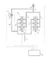
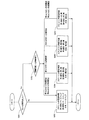
図1は、本実施例に係る内燃機関のEGR装置を適用する内燃機関とその吸気系及び排気系の概略構成を模式的に示す概念図である。 FIG. 1 is a conceptual diagram schematically showing a schematic configuration of an internal combustion engine to which an EGR device for an internal combustion engine according to the present embodiment is applied and its intake system and exhaust system.
図1において、エンジン1は、3つの気筒4を含む第1バンク2と、3つの気筒5を含む第2バンク3と、がV字型に配置された6気筒V型エンジンである。第1バンク2には、第1バンク2の各気筒4に連通する第1個別吸気通路6が接続されている。第2バンク3には、第2バンク3の各気筒5に連通する第2個別吸気通路7が接続されている。第1個別吸気通路6と第2個別吸気通路7とは上流において共有吸気通路8に集合している。
In FIG. 1, the engine 1 is a 6-cylinder V-type engine in which a first bank 2 including three cylinders 4 and a second bank 3 including three cylinders 5 are arranged in a V shape. A first
第1バンク2には、第1バンク2の各気筒4に連通する第1個別排気通路10が接続されている。
A first
第2バンク3には、第2バンク3の各気筒5に連通する第2個別排気通路9が接続されている。 A second individual exhaust passage 9 that communicates with each cylinder 5 of the second bank 3 is connected to the second bank 3.
第1個別排気通路10と第2個別排気通路9とは下流において共有排気通路11に集合している。
The first
第1バンク2には、各気筒4の吸気バルブ(図示省略)のバルブタイミングを変更可能な第1吸気VVT機構16が備えられている。
The first bank 2 is provided with a first
第2バンク3には、各気筒5の吸気バルブ(図示省略)のバルブタイミングを変更可能な第2吸気VVT機構15が備えられている。
The second bank 3 is provided with a second
第1個別排気通路10と共有吸気通路8とは、EGR通路12によって連通している。第1バンク2から排出された排気の一部がEGR通路12によって取り出され、EGR通路12を通ってEGRガスとして共有吸気通路8に流入する。
The first
EGR通路12の途中にはEGR通路12を流れるEGRガスの流量を調節するEGR弁13が備えられている。EGR弁13の開度を測定するEGR弁開度センサ17が備えられている。共有吸気通路8におけるEGR通路12の接続箇所より上流側には、スロットル弁14が備えられている。
An
第1バンク2は、該第1バンク2から排出される排気の少なくとも一部がEGR通路12によって取り出され、EGRガスとして共有吸気通路8に流入させられるバンクであり、本発明における「EGR取り出し有りバンク」に相当する。
The first bank 2 is a bank in which at least a part of the exhaust gas discharged from the first bank 2 is taken out by the
一方、第2バンク3は、該第2バンク3から排出される排気の一部がEGR通路12によってEGRガスとして取り出されないバンクであり、本発明における「EGR取り出し無しバンク」に相当する。
On the other hand, the second bank 3 is a bank in which a part of the exhaust discharged from the second bank 3 is not taken out as EGR gas by the
EGR弁開度センサ17その他各種センサはECU18に接続され、その測定データがECU18に入力されるようになっている。また、ECU18には、EGR弁13、スロットル弁14、第1吸気VVT機構16、第2吸気VVT機構15その他各種の機器が接続され、ECU18によってこれらの機器の動作が制御されるようになっている。
The EGR
ECU18はエンジン1の運転を制御するコンピュータであり、各種の制御プログラムが記憶されたROM、制御プログラムを実行するCPU、測定データ等を一時的に記憶するRAM等の公知の構成を有する。
The
ECU18は、エンジン1の負荷や回転数等の運転状態を各種センサから入力される測定データに基づいて把握し、把握した運転状態に応じてEGR弁13やスロットル弁14等の各種機器に制御信号を送出する。
The
通常、EGR弁13の開度は、ECU18によって、エンジン1の運転状態に応じて予め定められた目標開度に制御される。このEGR弁13の目標開度は、エンジン1のエミッション性能や燃費性能等の要請を満たすべく予め適合された量のEGRガスが、第1バンク2及び第2バンク3に流入するように、エンジン1の運転状態に応じて定められ、ECU18のROMに記憶されている。
Normally, the opening degree of the
しかしながら、EGR弁13を駆動するアクチュエータの故障や異物の堆積等のトラブルによってEGR弁13が開固着(開弁状態で固着すること)した場合、EGR弁13の開度は開固着時の開度で固定してしまい、エンジン1の運転状態に応じたEGRガス量の制御ができなくなる。
However, when the
その場合、特に、開固着時の開度が目標開度より大きいような運転状態においては、吸気のEGRガス量が過多となり、燃焼不良を招く虞がある。 In that case, in particular, in an operating state in which the opening degree at the time of open fixation is larger than the target opening degree, the amount of EGR gas in the intake air becomes excessive, which may cause a combustion failure.
すなわち、EGR弁13が開固着した場合、第1バンク2は上述の本発明の説明における「EGR取り出し増大バンク」に相当することになる。
That is, when the
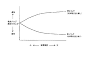
そこで、本実施例のEGR装置では、EGR弁13が開固着したことを検知した場合、EGR取り出し増大バンクである第1バンク2の気筒4の吸気バルブの閉弁タイミングを、EGR弁13が開固着していない通常時の図2(A1)に示すような閉弁タイミングに対して、図2(B1)に示すように遅角した閉弁タイミングになるように、第1吸気VVT機構16を制御することとした。
Therefore, in the EGR device of the present embodiment, when it is detected that the
第1バンク2の吸気バルブの閉弁タイミングを遅角させることにより、第1バンク2の吸気量が減少する。従って、第1バンク2から排出される排気の量も減少し、第1個別排気通路10からEGR通路12によってEGRガスとして取り出される排気の量も少なくなる。
By retarding the closing timing of the intake valve of the first bank 2, the intake amount of the first bank 2 decreases. Therefore, the amount of exhaust discharged from the first bank 2 is also reduced, and the amount of exhaust taken out as EGR gas from the first
その結果、EGR弁13が開固着した状態であっても、EGR通路12を通って共有吸気通路8に流入するEGRガス量が、通常時よりも過剰に多くならないようにすることが可能となる。
As a result, even when the
これにより、EGR弁13が開固着しても吸気のEGRガス量が過多となることが抑制され、燃焼不良の発生を抑制することができる。
Thereby, even if the
なお、EGR弁13が開固着したことが検知されたか否かに応じて、第1バンク2の吸気バルブの閉弁タイミングを、通常タイミングと、それより遅角させたタイミングと、の2通りの閉弁タイミングのいずれかに切り替えるようにしても良いが、EGR弁13の開固着の状況に応じて、よりきめ細かく第1バンク2の吸気バルブの閉弁タイミングを制御しても良い。
Depending on whether or not it is detected that the
例えば、図3に示すように、開固着時のEGR弁13の開度が開き側の開度(大開度)であるほど、第1バンク2(EGR取り出し増大バンク)の吸気バルブの閉弁タイミングをより遅角させるようにしても良い。
For example, as shown in FIG. 3, the closing timing of the intake valve of the first bank 2 (EGR take-out increase bank) becomes larger as the opening degree of the
この時、図3に示すように、第1バンク2の吸気バルブの閉弁タイミングを、EGR弁13の固着開度に応じて連続的に変化させても良いし、段階的に変化させるようにしても良い。
At this time, as shown in FIG. 3, the closing timing of the intake valve of the first bank 2 may be continuously changed according to the fixing opening degree of the
このようにすれば、EGR弁13の固着開度に応じて最適な量だけ、第1バンク2から排出される排気の量を減少させることができるので、EGR弁13の開固着時の燃焼不良をより確実に抑制することが可能となる。
In this way, the amount of exhaust discharged from the first bank 2 can be reduced by an optimum amount according to the degree of opening of the
また、開固着時のEGR弁13の開度と、目標開度と、を比較して、開固着時の開度の方が目標開度より開き側である場合に限って、第1バンク2の吸気バルブの閉弁タイミングを遅角させる制御を行うようにしても良い。
Further, the opening degree of the
これは、開固着時の開度が目標開度より閉じ側である場合には、EGR弁13が開固着していてもEGRガス量が過多となって燃焼不良が生じる可能性は低いからである。
This is because if the opening at the time of open fixation is closer to the target opening, even if the
ところで、このようにEGR弁13の開固着が検知された場合に、第1バンク2の吸気量が減少させられると、第1バンク2のトルクが低下する。このトルク低下の度合が大きいと、退避走行を支障なく行うための十分なトルクを確保できなくなる虞がある。
By the way, when the open adhering of the
そこで、本実施例のEGR装置では、EGR弁13の開固着の検知時に、上記のようにEGR取り出し増大バンクである第1バンク2の吸気バルブの閉弁タイミングを遅角させる制御を行うとともに、更に、EGR取り出し無しバンクである第2バンク3の吸気バル
ブの閉弁タイミングを、EGR弁13が開固着していない通常時における図2(A2)に示すような閉弁タイミングに対して、図2(B2)に示すように進角した閉弁タイミングになるように、第2吸気VVT機構15を制御することとした。
Therefore, in the EGR device of the present embodiment, when the open fixing of the
第2バンク3の吸気バルブの閉弁タイミングを進角させることにより、第2バンク3の吸気量が増加する。これに応じて第2バンク3の燃料噴射量を増量することにより、第2バンク3のトルクを増大させることが可能となる。 By advancing the closing timing of the intake valve of the second bank 3, the intake amount of the second bank 3 increases. In response to this, the torque of the second bank 3 can be increased by increasing the fuel injection amount of the second bank 3.
これにより、EGR弁13の開固着検知時に第1バンク2の吸気量を減少させる制御を実行しても、トルク不足になることを抑制でき、退避走行のための十分なトルクを確保することが可能となる。
As a result, even when the control for reducing the intake air amount of the first bank 2 is executed when the
なお、上記の第1バンク2の吸気バルブの閉弁タイミングを遅角させる場合と同様に、EGR弁13が開固着したことが検知されたか否かに応じて、第2バンク3の吸気バルブの閉弁タイミングを、通常タイミングと、それより進角させたタイミングと、の2通りの閉弁タイミングのいずれかに切り替えるようにしても良いが、EGR弁13の開固着の状況に応じて、よりきめ細かく第2バンク3の吸気バルブの閉弁タイミングを制御しても良い。
Note that, similarly to the case where the closing timing of the intake valve of the first bank 2 is retarded, the intake valve of the second bank 3 is determined depending on whether or not the
例えば、図3に示すように、開固着時のEGR弁13の開度が開き側の開度(大開度)であるほど、第2バンク3(EGR取り出し無しバンク)の吸気バルブの閉弁タイミングをより進角させるようにしても良い。
For example, as shown in FIG. 3, the closing timing of the intake valve of the second bank 3 (the bank without EGR removal) becomes larger as the opening degree of the
この時、図3に示すように、第2バンク3の吸気バルブの閉弁タイミングを、EGR弁13の固着開度に応じて連続的に変化させても良いし、段階的に変化させるようにしても良い。
At this time, as shown in FIG. 3, the closing timing of the intake valve of the second bank 3 may be continuously changed according to the fixing opening degree of the
このようにすれば、EGR弁13の固着開度に応じて第2バンク3のトルクを増加させることができるので、EGR弁13の開固着時のトルク不足をより確実に抑制することが可能となる。
In this way, the torque of the second bank 3 can be increased according to the fixing opening degree of the
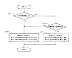
以上説明した本実施例の制御フローについて、図4に基づいて説明する。図4のフローチャートによって示されるルーチンは、エンジン1の稼働中定期的にECU18によって実行される。
The control flow of the present embodiment described above will be described with reference to FIG. The routine shown by the flowchart of FIG. 4 is periodically executed by the
ステップS101において、ECU18は、EGR弁13が開固着したか否かを判定する。本実施例では、EGR弁開度センサ17によって測定されるEGR弁13の実際の開度と、ECU18によって設定される目標開度とを比較し、目標開度の変化に対して実際の開度が変化していないことを検知した場合に、EGR弁13が開固着したと判定する。
In step S101, the
ステップS101でEGR弁13が開固着したと判定された場合(Yes)、ECU18はステップS102に進む。一方、ステップS101でEGR弁13が開固着していないと判定された場合(No)、ECU18はステップS103に進む。
If it is determined in step S101 that the
ステップS102において、ECU18は、EGR弁13の固着開度が目標開度よりも開き側であるか否かを判定する。
In step S102, the
ステップS102で固着開度が目標開度より開き側であると判定された場合(Yes)、ECU18はステップS104に進む。一方、ステップS102で固着開度が目標開度より開き側ではないと判定された場合(No)、ECU18はステップS103に進む。
If it is determined in step S102 that the fixed opening is on the opening side of the target opening (Yes), the
ステップS103において、ECU18は、第1バンク2及び第2バンク3の吸気バルブタイミング制御について、通常処理を実行する。すなわち、第1バンク2及び第2バンク3の吸気バルブの閉弁タイミングを、エンジン1の運転状態に応じて予め定められたベースマップ値に設定する。この場合、図2(A1)及び(A2)に示すように、第1バンク2の吸気バルブの閉弁タイミングも、第2バンク3の吸気バルブの閉弁タイミングも、同じタイミングに設定される。
In step S103, the
ステップS104において、ECU18は、第1バンク2及び第2バンク3の吸気バルブタイミング制御について、補正処理を実行する。すなわち、第1バンク2の吸気バルブの閉弁タイミングをベースマップ値よりも遅角したタイミングになるように第1吸気VVT機構16を制御するとともに、第2バンク3の吸気バルブの閉弁タイミングをベースマップ値よりも進角したタイミングになるように第2吸気VVT機構15を制御する。
In step S104, the
以上のルーチンを実行することにより、EGR弁13が開固着してその固着開度が目標開度より開き側の開度である場合においても、EGRガス量が過多になることが抑制され、燃焼不良が発生することを抑制することが可能になるとともに、退避走行のための十分なトルクを確保することが可能となる。
By executing the above routine, even when the
本実施例では、EGR取り出し有りバンクである第1バンク2の吸気量を制御する第1吸気VVT機構16が、本発明における吸気量制御手段、特に吸気VVT機構に相当する。
In the present embodiment, the first
ステップS101を実行してEGR弁13が開固着したか否かを判定するECU18が、本発明における故障検知手段に相当する。
The
ステップS103において特に第1バンク2の吸気バルブの閉弁タイミングをベースマップ値よりも遅角させる処理を行うECU18が、本発明における故障時制御手段に相当する。
In step S103, the
EGR取り出し無しバンクである第2バンク3の吸気量を制御する第2吸気VVT機構15が、本発明における第2吸気量制御手段、特に第2吸気VVT機構に相当する。
The second
ステップS103において、特に第2バンク3の吸気バルブの閉弁タイミングをベースマップ値よりも進角させる処理を行うECU18が、本発明における第2故障時制御手段に相当する。
In step S103, the
次に本発明の実施例2を説明する。図5は、本実施例に係る内燃機関のEGR装置を適用する内燃機関とその吸気系及び排気系の概略構成を模式的に示す概念図である。 Next, a second embodiment of the present invention will be described. FIG. 5 is a conceptual diagram schematically showing a schematic configuration of an internal combustion engine to which the EGR device for an internal combustion engine according to the present embodiment is applied, and its intake system and exhaust system.
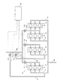
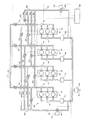
図5において、エンジン10は、3つの気筒21を含む第1バンク31と、3つの気筒22を含む第2バンク32と、3つの気筒23を含む第3バンク33と、3つの気筒24を含む第4バンク34と、を有する。
In FIG. 5, the
第1バンク31には、第1バンク31の気筒21に連通する第1個別吸気通路41が接続されている。
A first
第2バンク32には、第2バンク32の気筒22に連通する第2個別吸気通路42が接続されている。
The
第3バンク33及び第4バンク34には、第3バンク33の気筒23及び第4バンク34の気筒24に連通し、第3バンク33及び第4バンク34が共有する第1共有吸気通路430が接続されている。
The
第1個別吸気通路41には第1個別吸気通路41を流れる吸気の量を調節する第1個別スロットル弁61が備えられている。
The first
第2個別吸気通路42には第2個別吸気通路42を流れる吸気の量を調節する第2個別スロットル弁62が備えられている。
The second
第1共有吸気通路430には第1共有吸気通路430を流れる吸気の量を調節する共有スロットル弁630が備えられている。
The first shared
第1個別吸気通路41、第2個別吸気通路42、及び第1共有吸気通路430は、上流において全てのバンクが共有する第2共有吸気通路500に集合している。
The first
第1バンク31には、第1バンク31の気筒21に連通する第1個別排気通路71が接続されている。
A first individual exhaust passage 71 that communicates with the
第2バンク32には、第2バンク32の気筒22に連通する第2個別排気通路72が接続されている。
A second
第3バンク33には、第3バンク33の気筒23に連通する第3個別排気通路73が接続されている。
A third
第4バンク34には、第4バンク34の気筒24に連通する第4個別排気通路74が接続されている。
A fourth
第1個別排気通路71〜第4個別排気通路74は、下流において全てのバンクが共有する共有排気通路80に集合している。
The first individual exhaust passage 71 to the fourth
第1個別排気通路71と第2共有吸気通路500とは、第1EGR通路91によって連通している。第1バンク31から排出された排気の一部が第1EGR通路91によって取り出され、第1EGR通路91を通ってEGRガスとして第2共有吸気通路500に流入する。
The first individual exhaust passage 71 and the second shared
第2個別排気通路72と第2共有吸気通路500とは、第2EGR通路92によって連通している。第2バンク32から排出された排気の一部が第2EGR通路92によって取り出され、第2EGR通路92を通ってEGRガスとして第2共有吸気通路500に流入する。
The second
第1EGR通路91の途中には第1EGR通路91を流れるEGRガスの流量を調節する第1EGR弁101が備えられている。また、第1EGR弁101の開度を測定する第1EGR弁開度センサ111が備えられている。
A
第2EGR通路92の途中には第2EGR通路92を流れるEGRガスの流量を調節する第2EGR弁102が備えられている。また、第2EGR弁102の開度を測定する第2EGR弁開度センサ112が備えられている。
A
第1バンク31及び第2バンク32は、これらのバンクから排出される排気の少なくとも一部が第1EGR通路91又は第2EGR通路92によって取り出され、EGRガスとして第2共有吸気通路500に流入させられるバンクであり、本発明における「EGR取り出し有りバンク」に相当する。
In the
一方、第3バンク33及び第4バンク34は、これらのバンクから排出される排気の一部が第1EGR通路91及び第2EGR通路92のいずれによっても取り出されないバンクであり、本発明における「EGR取り出し無しバンク」に相当する。
On the other hand, the
第1EGR弁開度センサ111及び第2EGR弁開度センサ112その他各種センサはECU120に接続され、その測定データがECU120に入力されるようになっている。
The first EGR
また、ECU120には、第1EGR弁101、第2EGR弁102、第1個別スロットル弁61、第2個別スロットル弁62、共有スロットル弁630その他の各種の機器が接続され、ECU120によってこれらの機器の動作が制御されるようになっている。
Further, the
ECU120はエンジン1の運転を制御するコンピュータであり、各種の制御プログラムが記憶されたROM、制御プログラムを実行するCPU、測定データ等を一時的に記憶するRAM等の公知の構成を有する。ECU120は、エンジン1の負荷や回転数等の運転状態を各種センサから入力される測定データに基づいて把握し、把握した運転状態に応じて上記各種機器に制御信号を送出する。
The
第1EGR弁101又は第2EGR弁102が開固着した場合に起こり得る問題点については実施例1で説明した通りである。本実施例では、上記の構成を有するエンジンのEGR装置において、特に第1EGR弁101が開固着した場合に行われる制御について説明する。
Problems that may occur when the
第1EGR弁101が開固着した場合であって、固着開度がエンジン1の運転条件に応じてECU120が設定する目標開度より大きい開度となる場合には、吸気のEGRガス量が過多となって燃焼不良が発生する虞がある。
When the
すなわち、第1EGR弁101が開固着した場合、第1バンク31は上述の本発明の説明における「EGR取り出し増大バンク」に相当する。
That is, when the
一方、ここでは第2EGR弁102は開固着していない場合を想定しているので、第2バンク32は、本発明における「EGR取り出し有りバンク」ではあるが、「EGR取り出し増大バンク」ではない。
On the other hand, since it is assumed here that the
本実施例では、第1EGR弁101が開固着したことを検知した場合、EGR取り出し増大バンクである第1バンク31に接続された第1個別吸気通路41に設けられた第1個別スロットル弁61の開度を、第1EGR弁101が開固着していない通常時よりも閉じ側の開度に変更することとした。
In this embodiment, when it is detected that the
こうすることにより、第1バンク31に流入する吸気量が減少する。従って、第1バンク31から排出される排気の量も減少し、第1個別排気通路71から第1EGR通路91によってEGRガスとして取り出される排気の量も少なくなる。
By doing so, the amount of intake air flowing into the
その結果、第1EGR弁101が開固着した状態であっても、第1EGR通路91を通って第2共有吸気通路500に流入するEGRガス量が、通常時よりも過剰に多くならな
いようにすることが可能となる。
As a result, even when the
これにより、第1EGR弁101が開固着しても吸気のEGRガス量が過多となることが抑制され、燃焼不良の発生を抑制することができる。
Thereby, even if the
なお、実施例1と同様に、第1EGR弁101が開固着したことが検知されたか否かに応じて、第1個別スロットル弁61の開度を、通常開度と、それよりも閉じ側の所定開度と、の2通りの開度のいずれかに切り替えるようにしても良いが、第1EGR弁101の固着開度に応じて、よりきめ細かく第1個別スロットル弁61の開度を制御しても良い。
As in the first embodiment, the opening degree of the first
例えば、図6に示すように、第1EGR弁101の固着開度が開き側の開度(大開度)であるほど、第1個別スロットル弁61の開度をより閉じ側の開度に制御するようにしても良い。
For example, as shown in FIG. 6, the opening degree of the first
この時、図6に示すように、第1個別スロットル弁61の開度を、第1EGR弁101の固着開度に応じて連続的に変化させても良いし、段階的に変化させるようにしても良い。
At this time, as shown in FIG. 6, the opening degree of the first
このようにすれば、第1EGR弁101の固着開度に応じて最適な量だけ、第1バンク31から排出される排気の量を減少させることができるので、第1EGR弁101の開固着時の燃焼不良をより確実に抑制することが可能となる。
In this way, the amount of exhaust exhausted from the
また、開固着時の第1EGR弁101の固着開度と、エンジン1の運転条件に応じてECU120によって設定される目標開度と、を比較して、固着開度の方が目標開度より開き側である場合に限って、第1個別スロットル弁61の開度を閉じ側に変更する制御を行うようにしても良い。
Further, the fixed opening degree of the
このように、第1EGR弁101の開固着が検知された場合に、第1バンク31の吸気量が減少させられると、第1バンク31のトルクが低下する。このトルク低下の度合が大きいと、退避走行を支障なく行うための十分なトルクを確保できなくなる虞がある。
As described above, when the open adhesion of the
そこで、本実施例のEGR装置では、第1EGR弁101の開固着の検知時に、上記のようにEGR取り出し増大バンクである第1バンク31の個別スロットル弁61の開度を閉じ側の開度にする制御を行うとともに、更に、EGR取り出し増大バンク以外のバンクの個別スロットル弁、すなわち、EGR取り出し有りバンクではあるがEGR取り出し増大バンクではない第2バンク32の第2個別スロットル弁62、及び、EGR取り出し無しバンクである第3バンク33及び第4バンク34の共有スロットル弁630の開度を、第1EGR弁101が開固着していない通常時の開度よりも開き側の開度に変更することとした。
Therefore, in the EGR device of the present embodiment, when the
これにより、第2バンク32〜第4バンク34の吸気量が増大する。これに応じて第2バンク32〜第4バンク34の燃料噴射量を通常時よりも増量することにより、第2バンク32〜第4バンク34のトルクを増大させることが可能となる。
As a result, the intake air amount in the
これにより、第1EGR弁101の開固着検知時に第1バンク31の吸気量を減少させる制御を実行しても、トルク不足になることを抑制でき、退避走行のための十分なトルクを確保することが可能となる。
As a result, even if control is performed to reduce the intake air amount of the
なお、上記の第1バンク31の第1個別スロットル弁61の開度を閉じ側にする場合と同様に、第1EGR弁101が開固着したことが検知されたか否かに応じて、第2個別ス
ロットル弁62及び共有スロットル弁630の開度を、通常の開度と、それより開き側の開度と、の2通りの開度のいずれかに切り替えるようにしても良いが、第1EGR弁101の開固着の状況に応じて、よりきめ細かく第2個別スロットル弁62及び共有スロットル弁630の開度を制御しても良い。
Note that, similarly to the case where the opening degree of the first
例えば、図6に示すように、開固着時の第1EGR弁101の開度が開き側の開度(大開度)であるほど、第2個別スロットル弁62及び共有スロットル弁630の開度をより開き側の開度にしても良い。
For example, as shown in FIG. 6, the opening degree of the second
この時、図6に示すように、第2個別スロットル弁62及び共有スロットル弁630の開度を、第1EGR弁101の固着開度に応じて連続的に変化させても良いし、段階的に変化させるようにしても良い。
At this time, as shown in FIG. 6, the opening degree of the second
このようにすれば、第1EGR弁101の固着開度に応じて第2バンク32〜第4バンク34のトルクを増加させることができるので、第1EGR弁101の開固着時のトルク不足をより確実に抑制することが可能となる。なお、図6では第2個別スロットル弁62の開度と共有スロットル弁630の開度とを等しい開度にする例を示しているが、これらの開度は異なる開度であっても良い。
In this way, the torque of the
以上説明した本実施例の制御フローについて、図7に基づいて説明する。図7のフローチャートによって示されるルーチンは、エンジン1の稼働中定期的にECU120によって実行される。
The control flow of the present embodiment described above will be described with reference to FIG. The routine shown by the flowchart of FIG. 7 is periodically executed by the
ステップS201において、ECU120は、第1EGR弁101又は第2EGR弁102の少なくともいずれかに開固着したものが有るか否かを判定する。本実施例では、第1EGR弁開度センサ111によって測定される第1EGR弁101の実際の開度と、ECU120によって設定される目標開度とを比較し、目標開度の変化に対して実際の開度が変化していないことを検知した場合に、第1EGR弁101が開固着したと判定する。第2EGR弁102についても同様に開固着の有無を判定する。
In step S <b> 201, the
ステップS201において、第1EGR弁101又は第2EGR弁102の少なくともいずれかが開固着したと判定された場合、ECU120はステップS202に進む。一方、ステップS201において、第1EGR弁101及び第2EGR弁102のどちらも開固着していないと判定された場合、ECU120はステップS203に進む。
If it is determined in step S201 that at least one of the
ステップS202において、ECU120は、ステップS201で開固着したと判定されたEGR弁の固着開度が目標開度よりも開き側であるか否かを判定する。
In step S202, the
ステップS202において、開固着したEGR弁の固着開度が目標開度よりも開き側ではないと判定された場合、ECU120はステップS203に進む。
If it is determined in step S202 that the fixed opening degree of the opened EGR valve is not on the open side with respect to the target opening degree, the
ステップS203では、ECU120は、第1個別スロットル弁61、第2個別スロットル弁62、及び共有スロットル弁630の開度制御について、通常処理を実行する。すなわち、第1個別スロットル弁61、第2個別スロットル弁62、及び共有スロットル弁630の開度を、エンジン1の運転状態に応じて予め定められたベースマップ値に設定する。
In step S <b> 203, the
ステップS202において、開固着したEGR弁に少なくとも第1EGR弁101が含まれる場合であって、第1EGR弁101の固着開度が目標開度よりも開き側であると判定された場合、ECU120はステップS204に進む。
In step S202, if it is determined that the
ステップS204では、ECU120は、第1個別スロットル弁61、第2個別スロットル弁62、及び共有スロットル弁630の開度制御について、補正処理を実行する。すなわち、第1個別スロットル弁61の開度をベースマップ値よりも閉じ側の開度に制御するとともに、第2個別スロットル弁62及び共有スロットル弁630の開度をベースマップ値よりも開き側の開度に制御する。
In step S204, the
これにより、EGR取り出し増大バンクである第1バンク31からの排気の排出量が減少し、第1EGR通路91によって第1個別排気通路71から取り出される排気の量が減少するので、第1EGR弁101が目標開度よりも開き側の開度で開固着していても、吸気のEGRガス量が過多になることを抑制できる。
As a result, the amount of exhaust discharged from the
また、EGR取り出し有りバンクではあるがEGR取り出し増大バンクではない第2バンク32、EGR取り出し無しバンクである第3バンク33及び第4バンク34の吸気量が増加してこれらのバンクのトルクが増大するので、第1バンク31の吸気量の減少に伴うトルク不足を補うことができる。
Further, the intake air amount of the
ステップS202において、開固着したEGR弁に少なくとも第2EGR弁102が含まれる場合であって、第2EGR弁102の固着開度が目標開度よりも開き側であると判定された場合、ECU120はステップS205に進む。
In step S202, if it is determined that the EGR valve that is open and fixed includes at least the
ステップS205では、ECU120は、第1個別スロットル弁61、第2個別スロットル弁62、及び共有スロットル弁630の開度制御について、補正処理を実行する。すなわち、第2個別スロットル弁62の開度をベースマップ値よりも閉じ側の開度に制御するとともに、第1個別スロットル弁61及び共有スロットル弁630の開度をベースマップ値よりも開き側の開度に制御する。
In step S205, the
これにより、EGR取り出し増大バンクである第2バンク32からの排気の排出量が減少し、第2EGR通路92によって第2個別排気通路72から取り出される排気の量が減少するので、第2EGR弁102が目標開度よりも開き側の開度で開固着していても、吸気のEGRガス量が過多になることを抑制できる。
As a result, the amount of exhaust discharged from the
また、EGR取り出し有りバンクではあるがEGR取り出し増大バンクではない第1バンク31、EGR取り出し無しバンクである第3バンク33及び第4バンク34の吸気量が増加してこれらのバンクのトルクが増大するので、第2バンク32の吸気量の減少に伴うトルク不足を補うことができる。
Further, the intake air amount of the
ステップS202において、第1EGR弁101及び第2EGR弁102の両方が開固着した場合であって、第1EGR弁101の固着開度も第2EGR弁102の固着開度も目標開度よりも開き側であると判定された場合、ECU120はステップS206に進む。
In step S202, both the
ステップS206では、ECU120は、第1個別スロットル弁61、第2個別スロットル弁62、及び共有スロットル弁630の開度制御について、補正処理を実行する。すなわち、第1個別スロットル弁61の開度及び第2個別スロットル弁62の開度をベースマップ値よりも閉じ側の開度に制御するとともに、共有スロットル弁630の開度をベースマップ値よりも開き側の開度に制御する。
In step S <b> 206, the
これにより、EGR取り出し増大バンクである第1バンク31及び第2バンク32からの排気の排出量が減少し、第1EGR通路91によって第1個別排気通路71から取り出
される排気の量も、第2EGR通路92によって第2個別排気通路72から取り出される排気の量も、減少することになるので、第1EGR弁101及び第2EGR弁102が目標開度よりも開き側の開度で開固着していても、吸気のEGRガスが過多になることを抑制できる。
As a result, the amount of exhaust discharged from the
また、EGR取り出し無しバンクである第3バンク33及び第4バンク34の吸気量が増加してこれらのバンクのトルクが増大するので、第1バンク31及び第2バンク32の吸気量の減少に伴うトルク不足を補うことができる。
Further, since the intake air amount of the
以上のルーチンを実行することにより、第1EGR弁101や第2EGR弁102が開固着してその固着開度が目標開度より開き側の開度である場合においても、EGRガス量が過多になることが抑制され、燃焼不良が発生することを抑制することが可能になるとともに、退避走行のための十分なトルクを確保することが可能となる。
By executing the above routine, the EGR gas amount becomes excessive even when the
本実施例では、EGR取り出し有りバンクである第1バンク31に接続された第1個別吸気通路41と、第2バンク32に接続された第2個別吸気通路42とが、本発明における個別吸気通路に相当する。
In the present embodiment, the first
第1個別吸気通路41に設けられた第1個別スロットル弁61と、第2個別吸気通路42に設けられた第2個別スロットル弁62とが、本発明における個別スロットル弁に相当する。
The first
ステップS201を実行して第1EGR弁101又は第2EGR弁102に開固着したものが有るか否かを判定するECU120が、本発明における故障検知手段に相当する。
The
ステップS204、ステップS205、又はステップS206において第1個別スロットル弁61及び/又は第2個別スロットル弁62の開度をベースマップ値よりも閉じ側に制御する処理を行うECU120が、本発明における故障時制御手段に相当する。
In step S204, step S205, or step S206, the
EGR取り出し無しバンクである第3バンク33及び第4バンク34が共有する第1共有吸気通路430に設けられた共有スロットル弁630が、本発明における第2吸気量制御手段に相当する。
The shared
ステップS203、ステップS204、ステップS205、又はステップS206において共有スロットル弁630の開度をベースマップ値よりも開き側に制御する処理を行うECU120が、本発明における第2故障時制御手段に相当する。
The
なお、ステップS204、ステップS205、又はステップS206において、EGR取り出し有りバンクではあるがEGR取り出し増大バンクではないバンクの個別スロットル弁についてベースマップ値よりも開き側に制御する処理を行うECU120も、本発明における第2故障時制御手段に相当すると考えても良い。
In addition, in step S204, step S205, or step S206, the
次に、本発明の実施例3について説明する。図8は、本実施例に係る内燃機関のEGR装置を適用する内燃機関とその吸気系及び排気系の概略構成を模式的に示す概念図である。 Next, Embodiment 3 of the present invention will be described. FIG. 8 is a conceptual diagram schematically showing a schematic configuration of an internal combustion engine to which the EGR device for an internal combustion engine according to the present embodiment is applied and its intake system and exhaust system.
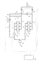
図8において、エンジン1は、3つの気筒21を含む第1バンク31と、3つの気筒22を含む第2バンク32と、がV字型に配置された6気筒V型エンジンである。第1バンク31には、第1バンク31の各気筒21に連通する第1個別吸気通路41が接続されて
いる。第2バンク32には、第2バンク32の各気筒22に連通する第2個別吸気通路42が接続されている。第1個別吸気通路41と第2個別吸気通路42とは上流において共有吸気通路50に集合している。
In FIG. 8, the engine 1 is a 6-cylinder V-type engine in which a
第1バンク31には、第1バンク31の各気筒21に連通する第1個別排気通路71が接続されている。
A first individual exhaust passage 71 that communicates with each
第2バンク32には、第2バンク32の各気筒22に連通する第2個別排気通路72が接続されている。
A second
第1個別排気通路71と第2個別排気通路72とは下流において共有排気通路80に集合している。
The first individual exhaust passage 71 and the second
第1個別排気通路71には、第1前段触媒141が配置されている。第2個別排気通路72には、第2前段触媒142が配置されている。共有排気通路80には、床下触媒150が配置されている。
A first
第1前段触媒141より下流側の第1個別排気通路71にはEGR通路91が接続されている。EGR通路91は途中の分岐部910において第1分岐通路911及び第2分岐通路912に分岐し、第1分岐通路911は第1個別吸気通路41に接続され、第2分岐通路912は第2個別吸気通路42に接続されている。
An
分岐部910より上流側のEGR通路91には、EGR通路91を流れるEGRガスの流量を調節するEGR弁101が備えられている。また、EGR弁101の開度を測定するEGR弁開度センサ111が備えられている。
An
また、第2分岐通路912の途中には、第2分岐通路912内のEGRガスが第2個別吸気通路42に流入することを遮断可能な遮断弁132が備えられている。
Further, a
第1バンク31から排出された排気の一部はEGR通路91によって取り出され、EGR通路91、第1分岐通路911、第2分岐通路912を通ってEGRガスとして第1個別吸気通路41及び第2個別吸気通路42に流入する。
A part of the exhaust gas discharged from the
第1個別吸気通路41における第1分岐通路911の接続箇所より上流側には第1個別スロットル弁61が備えられている。
A first
第2個別吸気通路42における第2分岐通路912の接続箇所より上流側には第2個別スロットル弁62が備えられている。
A second
第1バンク31は、該第1バンク31から排出される排気の少なくとも一部がEGR通路91によって取り出され、EGRガスとして第1個別吸気通路41及び第2個別吸気通路42に流入させられるバンクであり、本発明における「EGR取り出し有りバンク」に相当する。
The
一方、第2バンク32は、該第2バンク32から排出された排気の一部がEGR通路91によってEGRガスとして取り出されないバンクであり、本発明における「EGR取り出し無しバンク」に相当する。
On the other hand, the
EGR弁開度センサ111その他各種センサはECU120に接続され、その測定データがECU120に入力されるようになっている。また、ECU120には、EGR弁1
01、遮断弁132、第1個別スロットル弁61、第2個別スロットル弁62その他各種の機器が接続され、ECU120によってこれらの機器の動作が制御されるようになっている。
The EGR
01, the shut-off
ECU120はエンジン1の運転を制御するコンピュータであり、各種の制御プログラムが記憶されたROM、制御プログラムを実行するCPU、測定データ等を一時的に記憶するRAM等の公知の構成を有する。ECU120は、エンジン1の負荷や回転数等の運転状態を各種センサから入力される測定データに基づいて把握し、把握した運転状態に応じてEGR弁101や第1個別スロットル弁61や第2個別スロットル弁62等の各種機器に制御信号を送出する。
The
EGR弁101が開固着した場合、上述の各実施例において説明したように、EGRガス量が過多となって燃焼不良が発生する虞がある。すなわち、EGR弁101が開固着した場合、第1バンク31は上述の本発明の説明における「EGR取り出し増大バンク」に相当することになる。
When the
上記説明した各実施例では、EGR取り出し増大バンクの個別吸気VVT機構を制御して吸気バルブの閉弁タイミングを遅角させたり、個別スロットル弁の開度を閉じ側に変更したりすることにより、EGR取り出し増大バンクの吸気量を減少させる制御を行う場合について説明した。 In each of the embodiments described above, by controlling the individual intake VVT mechanism of the EGR take-out increase bank to retard the closing timing of the intake valve or changing the opening of the individual throttle valve to the closed side, The case where the control for reducing the intake amount of the EGR take-out increase bank has been described.
これに対し、本実施例では、EGR弁101が開固着したことを検知した場合、EGR取り出し増大バンクである第1バンク31において燃料カット制御を行うこととした。
On the other hand, in this embodiment, when it is detected that the
第1バンク31において燃料カット制御が行われることにより、第1バンク31から排出される排気は既燃ガスではなく空気になるので、EGR弁101の開固着によりEGRガス量が通常時より増大したとしても、そのEGRガスは既燃ガスではないので、吸気中の不活性成分が過多になることによる燃焼不良の発生を抑制することができる。
As the fuel cut control is performed in the
しかしながら、このように空気がEGRガスとして第1個別吸気通路41や第2個別吸気通路42に流入すると、特に燃料カット制御が行われない第2バンク32において、空燃比ずれが生じて燃焼が不安定になる可能性がある。
However, when air flows into the first
また、第2バンク32から排出される排気が通常時よりもリーンとなる虞があるため、第2前段触媒142や床下触媒150が過剰にリーンな排気に曝されて劣化する虞もある。
Further, since the exhaust discharged from the
そこで、本実施例では、EGR弁101の開固着を検知した時に、第1バンク31に対して燃料カット制御を実行するとともに、第1個別スロットル弁61の開度を通常時よりも閉じ側の開度に制御し、第2個別スロットル弁62の開度を通常時よりも開き側の開度に制御することとした。
Therefore, in this embodiment, when the open fixing of the
この時の第1個別スロットル弁61の開度は、第1バンク31の気筒21に負圧分の吸気量を補填する開度に設定し、第2個別スロットル弁62の開度は、第2バンク32へのEGRガスの流入を抑制可能な開度に設定する。
The opening degree of the first
第1個別スロットル弁61が通常時よりも閉じ側の開度に制御され、且つ、第2個別スロットル弁62が通常時よりも開き側の開度に制御されることにより、第1個別スロットル弁61より下流側の第1個別吸気通路41の圧力に対して、第2個別スロットル弁62より下流側の第2個別吸気通路42の圧力が高くなる。
The first
従って、EGR通路91内の空気EGRガスは、第2分岐通路912よりも第1分岐通路911の方に流入し易くなる。
Accordingly, the air EGR gas in the
これにより、第1バンク31から排出される排気(空気)は、EGR通路91によって第1個別排気通路71から取り出され、EGR通路91から第1分岐通路911にその大部分が流入し、第1分岐通路911を通過して第1個別吸気通路41に流入し、第1バンク31に流入することになる。
As a result, the exhaust (air) discharged from the
すなわち、燃料カット制御が行われる第1バンク31、第1個別排気通路71、EGR通路91、第1分岐通路911、第1個別吸気通路41を含む循環経路内を空気EGRガスが循環することになり、空気EGRガスが第2バンク32に流入することが抑制される。
That is, the air EGR gas circulates in the circulation path including the
更に、本実施例では、この時、遮断弁132を閉弁して、空気EGRガスの第2バンク32への流入をより確実に防止するようにした。
Further, in this embodiment, at this time, the
また、第2個別スロットル弁62の開度が通常時よりも開き側の開度とされることで、第2バンク32の吸気量が増加するので、これに応じて第2バンク32の燃料噴射量を増量することとした。
Further, since the opening amount of the second
こうすることにより、第2バンク32からの排気が過剰にリーンになることが抑制され、第2前段触媒142や床下触媒150が過剰にリーンな排気に曝されて劣化することを抑制することが可能となる。
By doing so, it is possible to suppress the exhaust from the
更に、第2バンク32のトルクが増大するので、第1バンク31における燃料カット制御に起因するトルク不足を補うことができる。従って、退避走行を支障なく行うための十分なトルクを確保することも可能となる。
Furthermore, since the torque of the
なお、EGR弁101が開固着したことが検知されたか否かに応じて、第1個別スロットル弁61及び第2個別スロットル弁62の開度がともに通常開度とされる制御パターンと、第1個別スロットル弁61の開度が通常開度よりも閉じ側の所定開度とされるとともに第2個別スロットル弁62の開度が通常開度よりも開き側の所定開度とされる制御パターンと、の2通りの制御パターンのいずれかに切り替えるようにしても良いが、EGR弁101の固着開度に応じて、よりきめ細かく第1個別スロットル弁61及び第2個別スロットル弁62の開度を制御しても良い。
A control pattern in which the opening degrees of the first
例えば、図9に示すように、EGR弁101の固着開度が開き側の開度(大開度)であるほど、第1個別スロットル弁61の開度をより閉じ側の開度に制御するとともに、第2個別スロットル弁62の開度をより開き側の開度に制御するようにしても良い。
For example, as shown in FIG. 9, the opening degree of the first
この時、図9に示すように、第1個別スロットル弁61及び第2個別スロットル弁62の開度を、EGR弁101の固着開度に応じて連続的に変化させても良いし、段階的に変化させるようにしても良い。
At this time, as shown in FIG. 9, the opening degree of the first
このようにすれば、EGR弁101の固着開度が大きい場合においても、より好適に空気EGRガスを第1バンク31を含む上述した循環経路内で循環させることができる。
In this way, even when the fixed opening degree of the
また、開固着時のEGR弁101の固着開度と、エンジン1の運転条件に応じてECU120によって設定される目標開度と、を比較して、固着開度の方が目標開度より開き側
である場合に限って、第1個別スロットル弁61の開度を閉じ側に変更するとともに第2個別スロットル弁62の開度を開き側に変更する制御を行うようにしても良い。
Further, the fixed opening of the
以上説明した本実施例の制御フローについて、図10に基づいて説明する。図10のフローチャートによって示されるルーチンは、エンジン1の稼働中定期的にECU120によって実行される。
The control flow of the present embodiment described above will be described with reference to FIG. The routine shown by the flowchart of FIG. 10 is periodically executed by the
ステップS301において、ECU120は、EGR弁101が開固着したか否かを判定する。本実施例では、EGR弁開度センサ111によって測定されるEGR弁101の実際の開度と、ECU120によって設定される目標開度とを比較し、目標開度の変化に対して実際の開度が変化していないことを検知した場合に、EGR弁101が開固着したと判定する。
In step S301, the
ステップS301でEGR弁101が開固着したと判定された場合(Yes)、ECU120はステップS302に進む。一方、ステップS301でEGR弁101が開固着していないと判定された場合(No)、ECU120はステップS303に進む。
If it is determined in step S301 that the
ステップS302において、ECU120は、EGR弁101の固着開度が目標開度よりも開き側であるか否かを判定する。
In step S302, the
ステップS302で固着開度が目標開度より開き側であると判定された場合(Yes)、ECU120はステップS304に進む。一方、ステップS302で固着開度が目標開度より開き側ではないと判定された場合(No)、ECU120はステップS303に進む。
If it is determined in step S302 that the fixed opening is on the opening side of the target opening (Yes), the
ステップS303において、ECU120は、第1個別スロットル弁61の開度、第2個別スロットル弁62の開度、第1バンク31の燃料噴射量、及び第2バンク32の燃料噴射量について、通常処理を実行する。
In step S303, the
すなわち、第1個別スロットル弁61の開度及び第2個別スロットル弁62の開度を、エンジン1の運転状態に応じて予め定められたベースマップ値に設定する。
That is, the opening degree of the first
更に、第1バンク31及び第2バンク32の燃料噴射量を、エンジン1の運転状態に応じて予め定められたベースマップ値に設定する。また、遮断弁132を開弁する。
Further, the fuel injection amounts of the
ステップS304において、ECU120は、第1個別スロットル弁61の開度、第2個別スロットル弁62の開度、第1バンク31の燃料噴射量、及び第2バンク32の燃料噴射量について、補正処理を実行する。
In step S304, the
すなわち、第1個別スロットル弁61の開度をベースマップ値よりも閉じ側の開度に変更するとともに、第2個別スロットル弁62の開度をベースマップ値よりも開き側の開度に変更する。
That is, the opening degree of the first
更に、第1バンク31において燃料カット制御を行うとともに、第2バンク32の燃料噴射量をベースマップ値よりも増量する。第2バンク32の燃料噴射量の増量分は、第2個別スロットル弁62の開度がベースマップ値よりも開き側の開度に変更されることに伴って増加する吸気量に応じて、空燃比がストイキになるように再計算した燃料噴射量に基づいて定められる。また、遮断弁132を閉弁する。
Further, fuel cut control is performed in the
以上のルーチンを実行することにより、EGR弁101が開固着してその固着開度が目
標開度よりも開き側の開度である場合において、第1バンク31において燃料カット制御が行われる場合においても、多量の空気EGRガスが第2バンク32に流入して第2バンク32からの排気が過剰にリーンになることが抑制される。よって、第2バンク32下流の第2前段触媒142や床下触媒150が過剰にリーンな排気に曝されて劣化することを好適に抑制することが可能となる。
By executing the above routine, when the
本実施例では、遮断弁132が、本発明における遮断装置に相当する。また、EGR弁101の開固着検知時に、ステップS304において、第1個別スロットル弁61の開度をベースマップ値よりも閉じ側の開度に変更し、第2個別スロットル弁62の開度をベースマップ値よりも開き側の開度に変更し、遮断弁132を閉弁し、燃料噴射量を増量するECU120が、本発明における故障時制御手段に相当する。
In this embodiment, the
次に、本発明の実施例4を説明する。本実施例は、実施例3で説明したような、EGR取り出し増大バンクにおいて燃料カット制御を行うとともに、燃料カット制御中のEGR取り出し増大バンクからの排気に由来する空気EGRガスがEGR取り出し増大バンクを含む循環経路内で循環するように個別スロットル弁を制御する構成を、実施例2のように2個のEGR取り出し有りバンクと、2個のEGR取り出し無しバンクと、を有するシステムに適用した実施例である。 Next, a fourth embodiment of the present invention will be described. In this embodiment, the fuel cut control is performed in the EGR take-out increase bank as described in the third embodiment, and the air EGR gas derived from the exhaust gas from the EGR take-out increase bank during the fuel cut control is set in the EGR take-out increase bank. An embodiment in which the configuration for controlling the individual throttle valve so as to circulate in the circulation path including it is applied to a system having two EGR extraction banks and two EGR extraction banks as in the second embodiment. It is.
図11は、本実施例に係る内燃機関のEGR装置を適用する内燃機関とその吸気系及び排気系の概略構成を模式的に示す概念図である。 FIG. 11 is a conceptual diagram schematically showing a schematic configuration of an internal combustion engine to which the EGR device for an internal combustion engine according to the present embodiment is applied and its intake system and exhaust system.
図11において、エンジン100は、3つの気筒21を含む第1バンク31と、3つの気筒22を含む第2バンク32と、3つの気筒23を含む第3バンク33と、3つの気筒24を含む第4バンク34と、を有する。
In FIG. 11, the
第1バンク31には、第1バンク31の気筒21に連通する第1個別吸気通路41が接続されている。
A first
第2バンク32には、第2バンク32の気筒22に連通する第2個別吸気通路42が接続されている。
The
第3バンク33には、第3バンク33の気筒23に連通する第3個別吸気通路43が接続されている。
A third
第4バンク34には、第4バンク34の気筒24に連通する第4個別吸気通路44が接続されている。
A fourth
第1個別吸気通路41には第1個別吸気通路41を流れる吸気の量を調節する第1個別スロットル弁61が備えられている。
The first
第2個別吸気通路42には第2個別吸気通路42を流れる吸気の量を調節する第2個別スロットル弁62が備えられている。
The second
第3個別吸気通路43には第3個別吸気通路43を流れる吸気の量を調節する第3個別スロットル弁63が備えられている。
The third
第4個別吸気通路44には第4個別吸気通路44を流れる吸気の量を調節する第4個別スロットル弁64が備えられている。
The fourth
第1個別吸気通路41、第2個別吸気通路42、第3個別吸気通路43、及び第4個別吸気通路44は、上流において全てのバンクが共有する共有吸気通路50に集合している。
The first
第1バンク31には、第1バンク31の気筒21に連通する第1個別排気通路71が接続されている。
A first individual exhaust passage 71 that communicates with the
第2バンク32には、第2バンク32の気筒22に連通する第2個別排気通路72が接続されている。
A second
第3バンク33には、第3バンク33の気筒23に連通する第3個別排気通路73が接続されている。
A third
第4バンク34には、第4バンク34の気筒24に連通する第4個別排気通路74が接続されている。
A fourth
第1個別排気通路71、第2個別排気通路72、第3個別排気通路73、及び第4個別排気通路74は、下流において全てのバンクが共有する共有排気通路80に集合している。
The first individual exhaust passage 71, the second
第1個別排気通路71には、第1前段触媒141が配置されている。
A first
第2個別排気通路72には、第2前段触媒142が配置されている。
A second
第3個別排気通路73には、第3前段触媒143が配置されている。
A third
第4個別排気通路74には、第4前段触媒144が配置されている。
A fourth
共有排気通路80には、床下触媒150が配置されている。
An
第1前段触媒141より下流側の第1個別排気通路71には第1EGR通路91が接続されている。
A
第1EGR通路91は途中の分岐部910において第1分岐通路911、第2分岐通路912、第3分岐通路913、及び第4分岐通路914に分岐している。
The
第1分岐通路911は第1個別吸気通路41に接続されている。
The
第2分岐通路912は第2個別吸気通路42に接続されている。
The
第3分岐通路913は第3個別吸気通路43に接続されている。
The
第4分岐通路914は第4個別吸気通路44に接続されている。
The
分岐部910より上流側の第1EGR通路91には、第1EGR通路91を流れるEGRガスの流量を調節する第1EGR弁101が備えられている。また、第1EGR弁101の開度を測定する第1EGR弁開度センサ111が備えられている。
A
第1分岐通路911の途中には、第1分岐通路内のEGRガスが第1個別吸気通路41
に流入することを遮断可能な遮断弁131が備えられている。
In the middle of the
There is provided a shut-off
第2分岐通路912の途中には、第2分岐通路内のEGRガスが第2個別吸気通路42に流入することを遮断可能な遮断弁132が備えられている。
In the middle of the
第3分岐通路913の途中には、第3分岐通路内のEGRガスが第3個別吸気通路43に流入することを遮断可能な遮断弁133が備えられている。
In the middle of the
第4分岐通路914の途中には、第4分岐通路内のEGRガスが第4個別吸気通路44に流入することを遮断可能な遮断弁134が備えられている。
In the middle of the
第1バンク31から排出された排気の一部は第1EGR通路91によって取り出され、第1EGR通路91を通過し、第1分岐通路911〜第4分岐通路914を通ってEGRガスとして第1個別吸気通路41〜第4個別吸気通路44に流入する。
A part of the exhaust discharged from the
第2前段触媒142より下流側の第2個別排気通路72には第2EGR通路92が接続されている。
A
第2EGR通路92は途中の分岐部920において第1分岐通路921、第2分岐通路922、第3分岐通路923、及び第4分岐通路924に分岐している。
The
第1分岐通路921は第1個別吸気通路41に接続されている。
The
第2分岐通路922は第2個別吸気通路42に接続されている。
The
第3分岐通路923は第3個別吸気通路43に接続されている。
The
第4分岐通路924は第4個別吸気通路44に接続されている。
The
分岐部920より上流側の第2EGR通路92には、第2EGR通路92を流れるEGRガスの流量を調節する第2EGR弁102が備えられている。また、第2EGR弁102の開度を測定する第2EGR弁開度センサ112が備えられている。
A
第1分岐通路921の途中には、第1分岐通路内のEGRガスが第1個別吸気通路41に流入することを遮断可能な遮断弁231が備えられている。
In the middle of the
第2分岐通路922の途中には、第2分岐通路内のEGRガスが第2個別吸気通路42に流入することを遮断可能な遮断弁232が備えられている。
In the middle of the
第3分岐通路923の途中には、第3分岐通路内のEGRガスが第3個別吸気通路43に流入することを遮断可能な遮断弁233が備えられている。
In the middle of the
第4分岐通路924の途中には、第4分岐通路内のEGRガスが第4個別吸気通路44に流入することを遮断可能な遮断弁234が備えられている。
In the middle of the
第2バンク32から排出された排気の一部は第2EGR通路92によって取り出され、第2EGR通路92を通過し、第1分岐通路921〜第4分岐通路924を通ってEGRガスとして第1個別吸気通路41〜第4個別吸気通路44に流入する。
A part of the exhaust discharged from the
第1個別吸気通路41における第1分岐通路911の接続箇所より上流側且つ第1分岐
通路921の接続箇所より上流側の位置には、第1個別スロットル弁61が備えられている。
A first
第2個別吸気通路42における第2分岐通路912の接続箇所より上流側且つ第2分岐通路922の接続箇所より上流側の位置には、第2個別スロットル弁62が備えられている。
A second
第3個別吸気通路43における第3分岐通路913の接続箇所より上流側且つ第3分岐通路923の接続箇所より上流側の位置には、第3個別スロットル弁63が備えられている。
A third
第4個別吸気通路44における第4分岐通路914の接続箇所より上流側且つ第4分岐通路924の接続箇所より上流側の位置には、第4個別スロットル弁64が備えられている。
A fourth
第1バンク31及び第2バンク32は、これらバンクから排出される排気の少なくとも一部が第1EGR通路91又は第2EGR通路92によって取り出され、EGRガスとして第1個別吸気通路41〜第4個別吸気通路44に流入させられるバンクであり、本発明における「EGR取り出し有りバンク」に相当する。
In the
一方、第3バンク33及び第4バンク34は、これらのバンクから排出された排気の一部が第1EGR通路91及び第2EGR通路92のいずれによってもEGRガスとして取り出されないバンクであり、本発明における「EGR取り出し無しバンク」に相当する。
On the other hand, the
第1EGR弁開度センサ111及び第2EGR弁開度センサ112その他各種センサはECU120に接続され、その測定データがECU120に入力されるようになっている。
The first EGR
また、ECU120には、第1EGR弁101、第2EGR弁102、第1個別スロットル弁61、第2個別スロットル弁62、第3個別スロットル弁63、第4個別スロットル弁64、遮断弁131、遮断弁132、遮断弁133、遮断弁134、遮断弁231、遮断弁232、遮断弁233、遮断弁234その他の各種の機器が接続され、ECU120によってこれらの機器の動作が制御されるようになっている。
Further, the
ECU120は、エンジン1の運転を制御するコンピュータであり、各種の制御プログラムが記憶されたROM、制御プログラムを実行するCPU、測定データ等を一時的に記憶するRAM等の公知の構成を有する。ECU120は、エンジン1の負荷や回転数等の運転状態を各種センサから入力される測定データに基づいて把握し、把握した運転状態に応じて上記各種機器に制御信号を送出する。
The
ここでは、2つのEGR弁のうち、特に第1EGR弁101が開固着した場合を例に、本実施例のシステムにおいて行われる制御について説明する。
Here, the control performed in the system of the present embodiment will be described by taking, as an example, the case where the
第1EGR弁101が開固着した場合であって、固着開度がエンジン1の運転条件に応じてECU120が設定する目標開度より大きい開度となる場合には、吸気のEGRガス量が過多となって燃焼不良が発生する虞がある。
When the
すなわち、第1EGR弁101が開固着した場合、第1バンク31は上述の本発明の説明における「EGR取り出し増大バンク」に相当する。
That is, when the
一方、ここでは第2EGR弁102は開固着していない場合を想定しているので、第2バンク32は、本発明における「EGR取り出し有りバンク」ではあるが、「EGR取り出し増大バンク」ではない。
On the other hand, since it is assumed here that the
本実施例では、第1EGR弁101が開固着したことを検知した場合、EGR取り出し増大バンクである第1バンク31において燃料カット制御を行う。
In this embodiment, when it is detected that the
さらに、第1個別スロットル弁61の開度を通常時よりも閉じ側の開度に制御し、第2個別スロットル弁62、第3個別スロットル弁63、及び第4個別スロットル弁64の開度を通常時よりも開き側の開度に制御する。
Further, the opening degree of the first
そして、第2バンク32〜第4バンク34の燃料噴射量を通常時よりも増量する。
Then, the fuel injection amount of the
第1個別スロットル弁61が通常時よりも閉じ側の開度に制御され、且つ、第2個別スロットル弁62、第3個別スロットル弁63、及び第4個別スロットル弁64の開度が通常時よりも開き側の開度に制御されることにより、第1個別スロットル弁61より下流側の第1個別吸気通路41の圧力に対して、第2個別スロットル弁62より下流側の第2個別吸気通路42、第3個別スロットル弁63より下流側の第3個別吸気通路43、第4個別スロットル弁64より下流側の第4個別吸気通路44の圧力が高くなる。
The opening degree of the first
従って、第1EGR通路91内の空気EGRガスは、第2分岐通路912〜第4分岐通路914よりも、第1分岐通路911の方に流入し易くなる。これにより、燃料カット制御が行われる第1バンク31から排出される排気(空気)は、第1EGR通路91によって第1個別排気通路71から取り出され、第1EGR通路91から第1分岐通路911にその大部分が流入し、第1分岐通路911を通過して第1個別吸気通路41に流入し、第1バンク31に流入することになる。
Therefore, the air EGR gas in the
すなわち、燃料カット制御が行われる第1バンク31、第1個別排気通路71、第1EGR通路91、第1分岐通路911、第1個別吸気通路41を含む循環経路内を空気EGRガスが循環することになり、空気EGRガスが第2バンク32〜第4バンク34へ流入することが抑制される。
That is, the air EGR gas circulates in the circulation path including the
更に、本実施例では、この時、遮断弁131を開弁し、遮断弁132、遮断弁133、遮断弁134を閉弁する。遮断弁231〜234は全て開弁する。
Further, in this embodiment, at this time, the
これにより、第1EGR通路91内のEGRガスが第2バンク32〜第4バンク34に流入することがより確実に防止される。
Thereby, it is more reliably prevented that the EGR gas in the
そして、第2個別スロットル弁62〜第4個別スロットル弁64の開度が通常時よりも開き側の開度とされることで、第2バンク32〜第4バンク34の吸気量が増加するが、これに応じて第2バンク32〜第4バンク34の燃料噴射量が増量されることにより、第2バンク32〜第4バンク34からの排気が過剰にリーンになることが抑制され、第2前段触媒142〜第4前段触媒144及び床下触媒150が過剰にリーンな排気に曝されて劣化することを抑制することが可能となる。
And since the opening degree of the 2nd individual throttle valve 62-the 4th
更に、第2バンク32〜第4バンク34のトルクが増大するので、第1バンク31の燃料カット制御に起因するトルク不足を補うことができる。従って、退避走行を支障なく行うための十分なトルクを確保することも可能となる。
Furthermore, since the torque of the
なお、実施例3と同様に、第1EGR弁101が開固着したことが検知されたか否かに
応じて、第1個別スロットル弁61〜第4個別スロットル弁64の開度が全て通常開度とされる制御パターンと、第1個別スロットル弁61の開度が通常開度よりも閉じ側の所定開度とされるとともに第2個別スロットル弁62〜第4個別スロットル弁64の開度が通常開度よりも開き側の所定開度とされる制御パターンと、の2通りの制御パターンのいずれかに切り替えるようにしても良いが、第1EGR弁101の固着開度に応じて、よりきめ細かく第1個別スロットル弁61〜第4個別スロットル弁64の開度を制御しても良い。
As in the third embodiment, all the opening degrees of the first
また、開固着時の第1EGR弁101の固着開度と、エンジン1の運転条件に応じてECU120によって設定される目標開度と、を比較して、固着開度の方が目標開度より開き側である場合に限って、上述した制御を行うようにしても良い。
Further, the fixed opening degree of the
以上説明した本実施例の制御フローについて、図12に基づいて説明する。図12のフローチャートによって示されるルーチンは、エンジン100の稼働中定期的にECU120によって実行される。
The control flow of the present embodiment described above will be described with reference to FIG. The routine shown by the flowchart of FIG. 12 is periodically executed by
ステップS401において、ECU120は、第1EGR弁101又は第2EGR弁102の少なくともいずれかに開固着したものが有るか否かを判定する。本実施例では、第1EGR弁開度センサ111によって測定される第1EGR弁101の実際の開度と、ECU120によって設定される目標開度とを比較し、目標開度の変化に対して実際の開度が変化していないことを検知した場合に、第1EGR弁101が開固着したと判定する。第2EGR弁102についても同様に開固着の有無を判定する。
In step S401, the
ステップS401において、第1EGR弁101又は第2EGR弁102の少なくともいずれかが開固着したと判定された場合、ECU120はステップS402に進む。一方、ステップS401において、第1EGR弁101及び第2EGR弁102のどちらも開固着していないと判定された場合、ECU120はステップS403に進む。
If it is determined in step S401 that at least one of the
ステップS402において、ECU120は、ステップS401で開固着したと判定されたEGR弁の固着開度が目標開度よりも開き側であるか否かを判定する。
In step S402, the
ステップS402において、開固着したEGR弁の固着開度が目標開度よりも開き側ではないと判定された場合、ECU120はステップS403に進む。
If it is determined in step S402 that the fixed opening degree of the opened EGR valve is not on the open side with respect to the target opening degree, the
ステップS403では、ECU120は、通常処理を実行する。すなわち、第1個別スロットル弁61〜第4個別スロットル弁64の開度を、エンジン1の運転状態に応じて予め定められたベースマップ値に設定する。また、第1バンク31〜第4バンク34の燃料噴射量をベースマップ値に設定する。また、全ての遮断弁を開弁する。
In step S403, the
ステップS402において、開固着したEGR弁に少なくとも第1EGR弁101が含まれる場合であって、第1EGR弁101の固着開度が目標開度よりも開き側であると判定された場合、ECU120はステップS404に進む。
In step S402, when it is determined that at least the
ステップS404では、ECU120は、第1バンク31において燃料カット制御を行う。そして、第1個別スロットル弁61の開度をベースマップ値よりも閉じ側の開度に制御するとともに、第2個別スロットル弁62〜第4個別スロットル弁64の開度をベースマップ値よりも開き側の開度に制御する。
In step S <b> 404, the
更に、遮断弁131、231〜234を開弁し、遮断弁132〜134を閉弁する。更に、第2バンク32〜第4バンク34の燃料噴射量をベースマップ値よりも増量する。
Further, the
これにより、EGR取り出し増大バンクであり燃料カット制御が行われる第1バンク31から排出される排気(空気)から取り出された空気EGRガスは、第1バンク31にのみ流入し、第2バンク32〜第4バンク34への流入が遮断される。従って、この空気EGRガスは第1バンク31を含む循環経路内で循環することになる。
As a result, the air EGR gas extracted from the exhaust (air) discharged from the
また、第2個別スロットル弁62〜第4個別スロットル弁64の開度が開き側の開度に制御されることによる第2バンク32〜第4バンク34の吸気量の増量に応じて第2バンク32〜第4バンク34の燃料噴射量が増量されるので、第2バンク32〜第4バンク34から排出される排気が過剰にリーンになることが抑制されるとともに、第2バンク32〜第4バンク34のトルクが増大する。
Further, the second bank according to the increase in the intake air amount of the
よって、第2前段触媒132〜第4前段触媒134及び床下触媒150に流入する排気が過剰にリーンになることを抑制できるとともに、第1バンク31の燃料カット制御に起因するトルク不足を補うことができる。
Therefore, it is possible to suppress the exhaust gas flowing into the second
ステップS402において、開固着したEGR弁に少なくとも第2EGR弁102が含まれる場合であって、第2EGR弁102の固着開度が目標開度よりも開き側であると判定された場合、ECU120はステップS405に進む。
In step S402, when it is determined that at least the
ステップS405では、ECU120は、第2バンク32において燃料カット制御を行う。そして、第2個別スロットル弁62の開度をベースマップ値よりも閉じ側の開度に制御するとともに、第1個別スロットル弁61、第3個別スロットル弁63、及び第4個別スロットル弁64の開度をベースマップ値よりも開き側の開度に制御する。
In step S <b> 405, the
更に、遮断弁232、131〜134を開弁し、遮断弁231、233、及び234を閉弁する。更に、第1バンク31、第3バンク33、及び第4バンク34の燃料噴射量をベースマップ値よりも増量する。
Further, the shut-off
これにより、EGR取り出し増大バンクであり燃料カット制御が行われる第2バンク32から排出される排気(空気)から取り出された空気EGRガスは、第2バンク32にのみ流入し、第1バンク31、第3バンク33、及び第4バンク34への流入が遮断される。従って、この空気EGRガスは第2バンク32を含む循環経路内で循環することになる。
As a result, the air EGR gas extracted from the exhaust (air) discharged from the
また、第1個別スロットル弁61、第3個別スロットル弁63、及び第4個別スロットル弁64の開度が開き側の開度に制御されることによる第1バンク31、第3バンク33、及び第4バンク34の吸気量の増量に応じて第1バンク31、第3バンク33、及び第4バンク34の燃料噴射量が増量されるので、第1バンク31、第3バンク33、及び第4バンク34から排出される排気が過剰にリーンになることが抑制されるとともに、第1バンク31、第3バンク33、及び第4バンク34のトルクが増大する。
Further, the
よって、第1前段触媒131、第3前段触媒133、第4前段触媒134、及び床下触媒150に流入する排気が過剰にリーンになることを抑制できるとともに、第2バンク32の燃料カット制御に起因するトルク不足を補うことができる。
Therefore, it is possible to prevent the exhaust flowing into the first
ステップS402において、第1EGR弁101及び第2EGR弁102の両方が開固着した場合であって、第1EGR弁101の固着開度も第2EGR弁102の固着開度も目標開度よりも開き側であると判定された場合、ECU120はステップS406に進む。
In step S402, both the
ステップS406では、ECU120は、第1バンク31及び第2バンク32において燃料カット制御を行う。そして、第1個別スロットル弁61及び第2個別スロットル弁62の開度をベースマップ値よりも閉じ側の開度に制御するとともに、第3個別スロットル弁63及び第4個別スロットル弁64の開度をベースマップ値よりも開き側の開度に制御する。
In step S <b> 406, the
更に、遮断弁131、132、231、232を開弁し、遮断弁133、134、233、234を閉弁する。更に、第3バンク33及び第4バンク34の燃料噴射量をベースマップ値よりも増量する。
Further, the
これにより、EGR取り出し増大バンクであり燃料カット制御が行われる第1バンク31及び第2バンク32から排出される排気(空気)から取り出された空気EGRガスは、第1バンク31及び第2バンク32にのみ流入し、第3バンク33及び第4バンク34への流入が遮断される。従って、この空気EGRガスは、第1バンク31を含む循環経路内及び/又は第2バンク32を含む循環経路内で循環することになる。
As a result, the air EGR gas extracted from the exhaust (air) exhausted from the
また、第3個別スロットル弁63及び第4個別スロットル弁64の開度が開き側の開度に制御されることによる第3バンク33及び第4バンク34の吸気量の増量に応じて第3バンク33及び第4バンク34の燃料噴射量が増量されるので、第3バンク33及び第4バンク34から排出される排気が過剰にリーンになることが抑制されるとともに、第3バンク33及び第4バンク34のトルクが増大する。
Further, the third bank according to the increase in the intake air amount of the
よって、第3前段触媒133、第4前段触媒134、及び床下触媒150に流入する排気が過剰にリーンになることを抑制できるとともに、第1バンク31及び第2バンク32の燃料カット制御に起因するトルク不足を補うことができる。
Therefore, it is possible to suppress the exhaust gas flowing into the third
以上のルーチンを実行することにより、第1EGR弁101や第2EGR弁102が開固着してその固着開度が目標開度より開き側の開度である場合において、第1バンク31や第2バンク32において燃料カット制御が行われる場合においても、多量の空気EGRガスが燃料カット制御が行われないバンクに流入してそれらのバンクからの排気が過剰にリーンになることが抑制される。
By executing the above routine, when the
よって、燃料カット制御が行われないバンク下流の前段触媒や床下触媒が過剰にリーン排気に曝されて劣化することを好適に抑制することが可能となる。 Therefore, it is possible to suitably suppress the deterioration of the upstream catalyst and the underfloor catalyst downstream of the bank where fuel cut control is not performed due to excessive exposure to the lean exhaust gas.
本実施例では、遮断弁131〜134、231〜234が本発明における遮断装置に相当する。
In this embodiment, the
本実施例において、第1EGR弁101及び/又は第2EGR弁102の開固着検知時に、ステップS404、ステップS405、又はステップS406の処理を行って、第1個別スロットル弁61及び/又は第2個別スロットル弁62の開度をベースマップ値よりも閉じ側の開度に変更し、それ以外の個別スロットル弁の開度をベースマップ値よりも開き側の開度に変更し、燃料カット制御が行われているEGR取り出し有りバンク由来の空気EGRガスが燃料カット制御が行われていないバンクへ流入するように遮断弁131〜134、231〜234の開閉制御を行うECU120が、本発明における故障時制御手段に相当する。
In the present embodiment, when the
本実施例において、第1EGR弁101又は第2EGR弁102のいずれかが開固着したことが検知された場合に、第1バンク31及び第2バンク32の両方のEGR取り出し
有りバンクに対して燃料カット制御を行うようにしても良い。
In this embodiment, when it is detected that either the
この場合、第1EGR通路91及び第2EGR通路92の両方が空気EGRガスを各個別吸気通路に流入させることになるので、第1個別スロットル弁61及び第2個別スロットル弁62の開度を閉じ側に変更し、第3個別スロットル弁63及び第4個別スロットル弁64の開度を開き側に変更するようにしても良い。
In this case, since both the
これにより、第1EGR通路91内のEGRガスは、第3分岐通路913及び第4分岐通路914よりも第1分岐通路911及び第2分岐通路912に流入し易くなり、また、第2EGR通路92内のEGRガスは、第3分岐通路923及び第4分岐通路924よりも第1分岐通路921及び第2分岐通路922に流入し易くなる。
As a result, the EGR gas in the
従って、燃料カット制御が行われる第1バンク31及び第2バンク32からの排気(空気)は、第1バンク31から排出され、第1EGR通路91及び第1分岐通路911を経て第1バンク31に戻る循環経路を循環し、第1バンク31から排出され、第1EGR通路91及び第2分岐通路912を経て第2バンク32を含む循環経路に流入し、第2バンク32から排出され、第2EGR通路92及び第2分岐通路922を経て第2バンク32に戻る循環経路を循環し、又は、第2バンク32から排出され、第2EGR通路92及び第1分岐通路921を経て第1バンク31を含む循環経路に流入する。
Therefore, the exhaust (air) from the
これにより、EGR取り出し無しバンクである第3バンク33及び第4バンク34に空気EGRガスが流入することが抑制される。そして、第3個別スロットル弁63及び第4個別スロットル弁64の開度が開き側に変更されることによる第3バンク33及び第4バンク34の吸気量の増大に応じて、第3バンク33及び第4バンク34の燃料噴射量が増量されるので、第3前段触媒143、第4前段触媒144、及び床下触媒150が過剰にリーンな排気に曝されて劣化することを抑制できるとともに、第1バンク31及び第2バンク32において燃料カット制御が行われることに起因するトルク不足を回避することが可能となる。
Thereby, it is suppressed that air EGR gas flows in into the
このようにEGR取り出し有りバンクを一律に燃料カット制御する場合、遮断弁は、各EGR通路からEGR取り出し無しバンクへのEGRガスの流入を遮断するものだけ備えれば十分である。 In this way, when the fuel cut control is uniformly performed on the bank with EGR removal, it is sufficient that the cutoff valve is provided only for blocking the inflow of EGR gas from each EGR passage to the bank without EGR removal.
すなわち、EGR取り出し無しバンク(第3バンク33、第4バンク34)の個別吸気通路(第3個別吸気通路43、第4個別吸気通路44)へのEGRガスの流入を遮断する遮断弁(遮断弁133、134、233、234)のみ備え、いずれかのEGR弁(第1EGR弁101、第2EGR弁102)の開固着検知時に第1バンク31及び第2バンク32において燃料カット制御が行われるのに応じて、遮断弁133、134、233、234を遮断するようにしても良い。
That is, the shutoff valve (shutoff valve) that shuts off the flow of EGR gas into the individual intake passages (third
なお、以上述べた実施例は本発明を説明するための一例であって、本発明の本旨を逸脱しない範囲内において上記の実施例には種々の変更を加え得る。 The above-described embodiment is an example for explaining the present invention, and various modifications can be made to the above-described embodiment without departing from the gist of the present invention.
例えば、上記実施例では1バンクあたり3つの気筒を有するバンクを2個又は4個有するエンジンシステムを例に説明したが、1バンク当たりの気筒の個数や、エンジンシステムが有するバンクの個数は上記実施例で例示した個数に限られない。 For example, in the above embodiment, an engine system having two or four banks having three cylinders per bank has been described as an example. However, the number of cylinders per bank and the number of banks included in the engine system are described above. It is not restricted to the number illustrated in the example.
また、実施例3及び4における前段触媒及び床下触媒の構成はこれに限る必要はない。少なくともEGR取り出し無しバンクから流出する排気が流通する箇所に少なくとも一つの排気浄化触媒を備えた構成を有するエンジンシステムであれば、本発明を適用すること
により、当該排気浄化触媒の劣化を抑制できるという本発明の効果を享受できる。
Moreover, the structure of the front | former stage catalyst and underfloor catalyst in Example 3 and 4 does not need to be restricted to this. If the engine system has a configuration including at least one exhaust purification catalyst at a location where the exhaust gas flowing out from the bank without EGR removal flows, it is possible to suppress deterioration of the exhaust purification catalyst by applying the present invention. The effects of the present invention can be enjoyed.
また、実施例1及び2では、EGR通路が共有吸気通路に接続される場合を例に説明したが、実施例1及び2において、EGR通路は、実施例3や4のように途中で分岐して各バンクの個別吸気通路に接続するように構成することもできる。 In the first and second embodiments, the case where the EGR passage is connected to the common intake passage has been described as an example. However, in the first and second embodiments, the EGR passage branches off in the middle as in the third and fourth embodiments. It can also be configured to connect to individual intake passages of each bank.
1 エンジン
2 第1バンク
3 第2バンク
4 気筒
5 気筒
6 第1個別吸気通路
7 第2個別吸気通路
8 共有吸気通路
9 第2個別排気通路
10 第1個別排気通路
11 共有排気通路
12 EGR通路
13 EGR弁
14 スロットル弁
15 第2吸気VVT機構
16 第1吸気VVT機構
17 EGR弁開度センサ
18 ECU
21 気筒
22 気筒
23 気筒
24 気筒
31 第1バンク
32 第2バンク
33 第3バンク
34 第4バンク
41 第1個別吸気通路
42 第2個別吸気通路
430 第1共有吸気通路
50 共有吸気通路
500 第2共有吸気通路
61 第1個別スロットル弁
62 第2個別スロットル弁
63 第3個別スロットル弁
64 第4個別スロットル弁
630 共有スロットル弁
71 第1個別排気通路
72 第2個別排気通路
73 第3個別排気通路
74 第4個別排気通路
80 共有排気通路
91 第1EGR通路
92 第2EGR通路
910 分岐部
911 第1分岐通路
912 第2分岐通路
913 第3分岐通路
914 第4分岐通路
920 分岐部
921 第1分岐通路
922 第2分岐通路
923 第3分岐通路
924 第4分岐通路
101 第1EGR弁
111 第1EGR弁開度センサ
102 第2EGR弁
112 第2EGR弁開度センサ
120 ECU
131 遮断弁
132 遮断弁
133 遮断弁
134 遮断弁
231 遮断弁
232 遮断弁
233 遮断弁
234 遮断弁
141 第1前段触媒
142 第2前段触媒
143 第3前段触媒
144 第4前段触媒
150 床下触媒
1 Engine 2 First bank 3 Second bank 4 Cylinder 5
21
131 shut-off
Claims (12)
前記複数のバンクのうちの一部のバンクである所定のEGR取り出し有りバンクからの排気の少なくとも一部を取り出してEGRガスとして前記内燃機関の吸気通路に流入させる一又は複数のEGR通路と、
前記各EGR通路に設けられたEGR弁と、
前記各EGR取り出し有りバンクへ流入する吸気量を制御する吸気量制御手段と、
前記各EGR弁の開固着を検知する故障検知手段と、
前記故障検知手段によって前記EGR弁の開固着が検知された場合に、前記EGR取り出し有りバンクのうち、当該開固着したEGR弁が設けられたEGR通路によってその排気の一部がEGRガスとして取り出されるように構成されているEGR取り出し有りバンクの吸気量を、EGR弁が開固着していない通常時よりも減少させる故障時制御手段と、を備えることを特徴とする内燃機関のEGR装置。 An internal combustion engine having a plurality of banks;
One or a plurality of EGR passages that take out at least a part of the exhaust from a bank with a predetermined EGR take-out that is a part of the plurality of banks and flow into the intake passage of the internal combustion engine as EGR gas;
An EGR valve provided in each EGR passage;
An intake air amount control means for controlling an intake air amount flowing into the bank with each EGR take-out,
A failure detection means for detecting open adhesion of each EGR valve;
When the failure detection means detects that the EGR valve is stuck open, a part of the exhaust gas is taken out as EGR gas by the EGR passage provided with the opened EGR valve in the EGR take-out bank. An EGR device for an internal combustion engine, comprising: a failure-time control means for reducing an intake air amount of an EGR take-out bank configured as described above from a normal time when the EGR valve is not open and fixed.
前記故障時制御手段は、前記開固着したEGR弁の開度が開き側の開度であるほど、当該開固着したEGR弁が設けられたEGR通路によってその排気の一部がEGRガスとして取り出されるEGR取り出し有りバンクの吸気量を、より減少させることを特徴とする内燃機関のEGR装置。 In claim 1,
As the opening degree of the open and fixed EGR valve is the opening side, the failure time control means extracts a part of the exhaust as EGR gas through the EGR passage provided with the open and fixed EGR valve. An EGR device for an internal combustion engine, wherein the intake air amount of the bank with EGR extraction is further reduced.
前記各EGR取り出し有りバンクに個別に接続された個別吸気通路を更に備え、
前記吸気量制御手段は、前記各個別吸気通路に設けられた個別スロットル弁を有し、
前記故障時制御手段は、前記故障検知手段によって前記EGR弁の開固着が検知された場合に、当該開固着したEGR弁が設けられたEGR通路によってその排気の一部がEGRガスとして取り出されるEGR取り出し有りバンクに接続された個別吸気通路に設けられた前記個別スロットル弁の開度を、EGR弁が固着していない通常時よりも閉じ側の開度にすることを特徴とする内燃機関のEGR装置。 In claim 1 or 2,
Further comprising individual intake passages individually connected to the EGR take-out banks,
The intake air amount control means has an individual throttle valve provided in each individual intake passage,
When the failure detection means detects that the EGR valve is stuck open, the failure time control means takes out part of the exhaust gas as EGR gas through the EGR passage provided with the open and stuck EGR valve. EGR of an internal combustion engine characterized in that the opening of the individual throttle valve provided in the individual intake passage connected to the take-out bank is set to an opening closer to the closing side than the normal time when the EGR valve is not fixed. apparatus.
前記吸気量制御手段は、前記各EGR取り出し有りバンクの気筒の吸気バルブタイミングを可変制御可能な吸気VVT機構を有し、
前記故障時制御手段は、前記故障検知手段によって前記EGR弁の開固着が検知された場合に、当該開固着したEGR弁が設けられたEGR通路によってその排気の一部がEGRガスとして取り出されるEGR取り出し有りバンクの気筒の吸気バルブの閉弁時期を、EGR弁が固着していない通常時よりも遅角させることを特徴とする内燃機関のEGR装置。 In claim 1 or 2,
The intake air amount control means has an intake VVT mechanism capable of variably controlling the intake valve timing of the cylinders in the bank with each EGR take-out,
When the failure detecting means detects that the EGR valve is stuck open, the failure control means is configured to take out part of the exhaust gas as EGR gas through the EGR passage provided with the open and stuck EGR valve. An EGR device for an internal combustion engine, wherein the closing timing of an intake valve of a cylinder in a take-out bank is delayed from a normal time when the EGR valve is not fixed.
前記故障時制御手段は、前記故障検知手段によって前記EGR弁の開固着が検知された場合に、当該開固着したEGR弁が設けられたEGR通路によってその排気の一部がEGRガスとして取り出されるEGR取り出し有りバンクの気筒に対して燃料カット制御を行うことを特徴とする内燃機関のEGR装置。 In any one of Claims 1-4,
When the failure detecting means detects that the EGR valve is stuck open, the failure control means is configured to take out part of the exhaust gas as EGR gas through the EGR passage provided with the open and stuck EGR valve. An EGR device for an internal combustion engine, characterized in that fuel cut control is performed on a cylinder in a take-out bank.
前記EGR通路は、その吸気通路側の端部が少なくとも前記各EGR取り出し有りバンクの個別吸気通路に接続されており、
前記各個別スロットル弁は、前記各個別吸気通路における前記EGR通路の接続箇所より上流側の位置に設けられており、
前記内燃機関の排気系に設けられた排気浄化装置を更に備え、
前記故障時制御手段は、前記故障検知手段によって前記EGR弁の開固着が検知された場合に、前記EGR取り出し有りバンクのうち、当該開固着したEGR弁が設けられたEGR通路によってその排気の一部がEGRガスとして取り出されるように構成されているEGR取り出し有りバンクの気筒に対して燃料カット制御を行うとともに、当該EGR取り出し有りバンクに接続された個別吸気通路に設けられた前記個別スロットル弁の開度を、EGR弁が開固着していない通常時よりも閉じ側の開度にすることを特徴とする内燃機関のEGR装置。 In claim 3,
The end of the EGR passage on the side of the intake passage is connected to at least the individual intake passage of each EGR take-out bank,
Each individual throttle valve is provided at a position upstream of a connection point of the EGR passage in each individual intake passage,
An exhaust purification device provided in an exhaust system of the internal combustion engine;
When the failure detection means detects that the EGR valve is open and stuck, the failure control means is configured to control the exhaust gas through an EGR passage provided with the open and stuck EGR valve in the EGR take-out bank. The fuel cut control is performed on the cylinders of the EGR take-out bank configured to take out the EGR gas as EGR gas, and the individual throttle valve provided in the individual intake passage connected to the EGR take-out bank An EGR device for an internal combustion engine, characterized in that the opening is set to an opening closer to the closing side than normal when the EGR valve is not open and fixed.
前記故障時制御手段は、前記開固着したEGR弁の開度が開き側の開度であるほど、当該開固着したEGR弁が設けられたEGR通路によってその排気の一部がEGRガスとして取り出されるEGR取り出し有りバンクに接続された個別吸気通路に設けられた個別スロットル弁の開度を、より閉じ側の開度にすることを特徴とする内燃機関のEGR装置。 In claim 6,
As the opening degree of the open and fixed EGR valve is the opening side, the failure time control means extracts a part of the exhaust as EGR gas through the EGR passage provided with the open and fixed EGR valve. An EGR device for an internal combustion engine, characterized in that an opening of an individual throttle valve provided in an individual intake passage connected to an EGR take-out bank is set to a close side opening.
前記EGR通路を流れるEGRガスが、前記各EGR通路のいずれによってもその排気の一部がEGRガスとして取り出されないバンクであるEGR取り出し無しバンクに流入することを、遮断可能な遮断装置を有し、
前記故障時制御手段は、前記故障検知手段によって前記EGR弁の開固着が検知された場合に、当該開固着したEGR弁が設けられたEGR通路から前記EGR取り出し無しバンクへEGRガスが流入することを、前記遮断装置により遮断することを特徴とする内燃機関のEGR装置。 In claim 6 or 7,
A shutoff device capable of shutting off EGR gas flowing through the EGR passage from flowing into a bank without EGR removal, which is a bank in which a part of the exhaust gas is not taken out as EGR gas by any of the EGR passages; ,
When the failure detecting means detects that the EGR valve is stuck open, the failure time control means causes an EGR gas to flow into the bank without EGR removal from the EGR passage provided with the opened EGR valve. Is shut off by the shut-off device.
前記各EGR通路のいずれによってもその排気の一部がEGRガスとして取り出されないバンクであるEGR取り出し無しバンクへ流入する吸気量を制御する第2吸気量制御手段と、
前記故障検知手段によって前記EGR弁の開固着が検知された場合に、前記EGR取り出し無しバンクの吸気量を、EGR弁が開固着していない通常時よりも増加させる第2故障時制御手段と、
を更に備えることを特徴とする内燃機関のEGR装置。 In any one of Claims 1-8,
A second intake air amount control means for controlling an intake air amount flowing into a bank without EGR removal, which is a bank where a part of the exhaust gas is not taken out as EGR gas by any of the EGR passages;
A second failure time control means for increasing an intake air amount of the bank without EGR removal when compared to a normal time when the EGR valve is not openly fixed when the failure detection means detects that the EGR valve is stuck open;
An EGR device for an internal combustion engine, further comprising:
前記第2故障時制御手段は、前記開固着したEGR弁の開度が開き側の開度であるほど、前記EGR取り出し無しバンクの吸気量を、より増加させることを特徴とする内燃機関のEGR装置。 In claim 9,
The EGR valve of the internal combustion engine, wherein the second failure time control means increases the intake air amount of the bank without EGR removal as the opening degree of the opened EGR valve is the opening side opening degree. apparatus.
前記各EGR取り出し無しバンクに個別に接続された個別吸気通路又は前記各EGR取り出し無しバンクが共有する共有吸気通路を更に備え、
前記第2吸気量制御手段は、前記各個別吸気通路に設けられた個別スロットル弁又は前記共有吸気通路に設けられた共有スロットル弁を有し、
前記第2故障時制御手段は、前記故障検知手段によって前記EGR弁の開固着が検知された場合に、前記個別スロットル弁又は前記共有スロットル弁の開度を、EGR弁が固着していない通常時よりも開き側の開度にすることを特徴とする内燃機関のEGR装置。 In claim 9 or 10,
An individual intake passage individually connected to each EGR no-takeout bank or a common intake passage shared by each EGR no-takeout bank,
The second intake amount control means has an individual throttle valve provided in each individual intake passage or a shared throttle valve provided in the shared intake passage,
When the EGR valve is stuck open by the failure detection means, the second failure time control means determines the opening degree of the individual throttle valve or the common throttle valve at a normal time when the EGR valve is not stuck. An EGR device for an internal combustion engine, characterized in that the opening degree is more open than that.
前記第2吸気量制御手段は、前記各EGR取り出し無しバンクの気筒の吸気バルブタイミングを可変制御可能な第2吸気VVT機構を有し、
前記第2故障時制御手段は、前記故障検知手段によって前記EGR弁の開固着が検知された場合に、前記EGR取り出し無しバンクの気筒の吸気バルブの閉弁時期を、EGR弁が開固着していない通常時よりも進角させることを特徴とする内燃機関のEGR装置。 In claim 9 or 10,
The second intake air amount control means has a second intake VVT mechanism capable of variably controlling the intake valve timing of the cylinders of each of the EGR removal-free banks,
The second failure time control means is configured such that when the failure detection means detects that the EGR valve is stuck open, the EGR valve is stuck open at the closing timing of the intake valve of the cylinder of the bank without EGR removal. An EGR device for an internal combustion engine characterized by being advanced more than normal.
Priority Applications (1)
| Application Number | Priority Date | Filing Date | Title |
|---|---|---|---|
| JP2008228897A JP4962453B2 (en) | 2008-09-05 | 2008-09-05 | EGR device for internal combustion engine |
Applications Claiming Priority (1)
| Application Number | Priority Date | Filing Date | Title |
|---|---|---|---|
| JP2008228897A JP4962453B2 (en) | 2008-09-05 | 2008-09-05 | EGR device for internal combustion engine |
Publications (2)
| Publication Number | Publication Date |
|---|---|
| JP2010059922A true JP2010059922A (en) | 2010-03-18 |
| JP4962453B2 JP4962453B2 (en) | 2012-06-27 |
Family
ID=42186979
Family Applications (1)
| Application Number | Title | Priority Date | Filing Date |
|---|---|---|---|
| JP2008228897A Expired - Fee Related JP4962453B2 (en) | 2008-09-05 | 2008-09-05 | EGR device for internal combustion engine |
Country Status (1)
| Country | Link |
|---|---|
| JP (1) | JP4962453B2 (en) |
Cited By (3)
| Publication number | Priority date | Publication date | Assignee | Title |
|---|---|---|---|---|
| WO2012107950A1 (en) * | 2011-02-08 | 2012-08-16 | トヨタ自動車株式会社 | Control device for internal combustion engine |
| US20160160811A1 (en) * | 2011-03-03 | 2016-06-09 | General Electric Company | Method and systems for exhaust gas control |
| JP2018071527A (en) * | 2016-11-04 | 2018-05-10 | トヨタ自動車株式会社 | Internal combustion engine control device |
Citations (5)
| Publication number | Priority date | Publication date | Assignee | Title |
|---|---|---|---|---|
| JPS60127442A (en) * | 1983-12-14 | 1985-07-08 | Fuji Xerox Co Ltd | Apparatus for measuring falling of rotary polyhedron mirror |
| JPH0544581A (en) * | 1991-08-09 | 1993-02-23 | Fuji Heavy Ind Ltd | Abnormality detecting method for exhaust gas reflux system for engine |
| JP2004360548A (en) * | 2003-06-04 | 2004-12-24 | Toyota Motor Corp | Control device for internal combustion engine |
| JP2009137531A (en) * | 2007-12-10 | 2009-06-25 | Toyota Motor Corp | Power output device for vehicle |
| JP2009257123A (en) * | 2008-04-14 | 2009-11-05 | Toyota Motor Corp | Control system for internal combustion engine |
-
2008
- 2008-09-05 JP JP2008228897A patent/JP4962453B2/en not_active Expired - Fee Related
Patent Citations (5)
| Publication number | Priority date | Publication date | Assignee | Title |
|---|---|---|---|---|
| JPS60127442A (en) * | 1983-12-14 | 1985-07-08 | Fuji Xerox Co Ltd | Apparatus for measuring falling of rotary polyhedron mirror |
| JPH0544581A (en) * | 1991-08-09 | 1993-02-23 | Fuji Heavy Ind Ltd | Abnormality detecting method for exhaust gas reflux system for engine |
| JP2004360548A (en) * | 2003-06-04 | 2004-12-24 | Toyota Motor Corp | Control device for internal combustion engine |
| JP2009137531A (en) * | 2007-12-10 | 2009-06-25 | Toyota Motor Corp | Power output device for vehicle |
| JP2009257123A (en) * | 2008-04-14 | 2009-11-05 | Toyota Motor Corp | Control system for internal combustion engine |
Cited By (7)
| Publication number | Priority date | Publication date | Assignee | Title |
|---|---|---|---|---|
| WO2012107950A1 (en) * | 2011-02-08 | 2012-08-16 | トヨタ自動車株式会社 | Control device for internal combustion engine |
| CN103348118A (en) * | 2011-02-08 | 2013-10-09 | 丰田自动车株式会社 | Control device for internal combustion engine |
| US20160160811A1 (en) * | 2011-03-03 | 2016-06-09 | General Electric Company | Method and systems for exhaust gas control |
| US10253731B2 (en) * | 2011-03-03 | 2019-04-09 | Ge Global Sourcing Llc | Method and systems for exhaust gas control |
| US20190234352A1 (en) * | 2011-03-03 | 2019-08-01 | Ge Global Sourcing Llc | Method and systems for exhaust gas control |
| US10844813B2 (en) * | 2011-03-03 | 2020-11-24 | Transportation Ip Holdings, Llc | Method and systems for exhaust gas control |
| JP2018071527A (en) * | 2016-11-04 | 2018-05-10 | トヨタ自動車株式会社 | Internal combustion engine control device |
Also Published As
| Publication number | Publication date |
|---|---|
| JP4962453B2 (en) | 2012-06-27 |
Similar Documents
| Publication | Publication Date | Title |
|---|---|---|
| JP4502038B2 (en) | Internal combustion engine control system | |
| US8676470B2 (en) | Multicylinder engine and method for controlling the same | |
| JP4462100B2 (en) | Exhaust device for internal combustion engine and control method for internal combustion engine | |
| JP4438759B2 (en) | Control device for internal combustion engine | |
| JP2010059921A (en) | Egr control device of internal combustion engine | |
| JP5403057B2 (en) | EGR control system for internal combustion engine | |
| JP4962453B2 (en) | EGR device for internal combustion engine | |
| JP2009270492A (en) | Failure diagnosis device of cylinder deactivation system | |
| JP2008190412A (en) | Supercharger control device for internal combustion engine | |
| US9080516B2 (en) | Diagnostic system and method for a variable valve lift mechanism | |
| JP2003206767A (en) | Valve timing control device for internal combustion engine | |
| JP2007032515A (en) | Internal combustion engine control device | |
| JP2007239471A (en) | Abnormality detection device for internal combustion engine | |
| JP5297257B2 (en) | Control device for internal combustion engine | |
| JP4935793B2 (en) | Control device for internal combustion engine | |
| JP2011220298A (en) | Device for controlling fuel injection of internal combustion engine | |
| JP5107214B2 (en) | Exhaust gas recirculation device for internal combustion engine | |
| JP2006307784A (en) | Control device for internal combustion engine | |
| JP4877288B2 (en) | Control device for internal combustion engine | |
| JP2008025527A (en) | Control unit for internal combustion engine | |
| JP2011052593A (en) | Device and method for controlling internal combustion engine | |
| JP5206531B2 (en) | Internal combustion engine control system | |
| JP2008223597A (en) | Exhaust control device for internal combustion engine | |
| JP2014227882A (en) | Engine cylinder number control device | |
| JP2008223490A (en) | Isc failure diagnosis device |
Legal Events
| Date | Code | Title | Description |
|---|---|---|---|
| A621 | Written request for application examination |
Free format text: JAPANESE INTERMEDIATE CODE: A621 Effective date: 20110125 |
|
| A977 | Report on retrieval |
Free format text: JAPANESE INTERMEDIATE CODE: A971007 Effective date: 20120217 |
|
| TRDD | Decision of grant or rejection written | ||
| A01 | Written decision to grant a patent or to grant a registration (utility model) |
Free format text: JAPANESE INTERMEDIATE CODE: A01 Effective date: 20120228 |
|
| A01 | Written decision to grant a patent or to grant a registration (utility model) |
Free format text: JAPANESE INTERMEDIATE CODE: A01 |
|
| A61 | First payment of annual fees (during grant procedure) |
Free format text: JAPANESE INTERMEDIATE CODE: A61 Effective date: 20120312 |
|
| FPAY | Renewal fee payment (event date is renewal date of database) |
Free format text: PAYMENT UNTIL: 20150406 Year of fee payment: 3 |
|
| LAPS | Cancellation because of no payment of annual fees |