JP2010059901A - Marine vertical shaft centrifugal pump and its component replacing method - Google Patents
Marine vertical shaft centrifugal pump and its component replacing method Download PDFInfo
- Publication number
- JP2010059901A JP2010059901A JP2008227871A JP2008227871A JP2010059901A JP 2010059901 A JP2010059901 A JP 2010059901A JP 2008227871 A JP2008227871 A JP 2008227871A JP 2008227871 A JP2008227871 A JP 2008227871A JP 2010059901 A JP2010059901 A JP 2010059901A
- Authority
- JP
- Japan
- Prior art keywords
- shaft
- coupling
- line bearing
- pump
- casing
- Prior art date
- Legal status (The legal status is an assumption and is not a legal conclusion. Google has not performed a legal analysis and makes no representation as to the accuracy of the status listed.)
- Granted
Links
Images


Abstract
Description
本発明は、船舶において海水等の水を揚水するための船用立軸遠心ポンプに関するものである。 The present invention relates to a marine vertical shaft centrifugal pump for pumping water such as seawater in a ship.
船舶、特に貨物船では積載貨物等の重量を含めて構造設計されているため、空荷だと船の重心が上がり、横波や横風に対して不安定となる。また空荷の場合、船体が浮き上がることでプロペラが水面近くとなるので、軸動力を推進力に変換する効率が低下する。 Ships, especially cargo ships, are structurally designed to include the weight of the loaded cargo, etc., so an empty load raises the center of gravity of the ship and makes it unstable against side waves and winds. Also, in the case of an empty load, the propeller is close to the water surface due to the hull being lifted, so the efficiency of converting shaft power into propulsion is reduced.
これらの問題点のために、空荷のときや貨物が少ないときには、船内に設けたバラストタンクに海水を積んで錘代わりとし、船体を安定させる方法が取られている。
このように、船舶ではそのときの貨物の量に応じてバラストタンクに海水を出し入れする必要があるので、大型のポンプが設置されている。
Because of these problems, when the cargo is empty or when there is little cargo, a method has been adopted in which the ballast tank provided in the ship is loaded with seawater to replace the weight and stabilize the hull.
Thus, since it is necessary for a ship to take in and out seawater to and from the ballast tank according to the amount of cargo at that time, a large pump is installed.
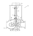
このようなポンプとしては、図5及び図6に示すように、モーターカップリング11と、ポンプカップリング12と、シャフト13と、メカニカルシール14と、ラインベアリング15と、インペラ16と、ケーシング17と、ケーシングカバー18とを備える船用立軸遠心ポンプ10が知られている。
As such a pump, as shown in FIGS. 5 and 6, a
このメカニカルシール14は、ケーシング17内の液が外部に漏れるのを防止するための軸封装置の一種であり、ポンプ運転中、シールリング14bは、フローティングシート14aと摺動しながら回転する。この摺動面に異物が侵入すると摺動面に傷がつき、そこから液体が外部に漏れる。また、パッキンの部分に異物が侵入するとシールリング14bの軸方向の動きが阻害され、これも漏れの原因となる。
The
この船用立軸遠心ポンプ10は2〜3年に1回程度の間隔で定期点検が行われるが、メカニカルシール14の漏洩事故はこの定期点検の時期に至らずに発生する事がよくある。
特に近年、砂等の異物を多量に含む河川沿岸の造船所で多くの船が建造されるようになり、また船の寄港地もそのような河口近辺が多くなったため、シールリング14bとフローティングシート14aとの摺動面に砂等が入ることも増え、メカニカルシール14の漏洩事故の頻度が上がっている。
The ship vertical shaft
In particular, in recent years, many ships have been built at riverside shipyards that contain a large amount of foreign substances such as sand, and the number of ship port calls has increased in the vicinity of such estuaries. The frequency of leakage accidents of the
一方、ラインベアリング15の損傷事故はメカニカルシール14ほどの頻度では発生しないが、やはり定期点検時期に至らずに突発的に損傷が発生することがある。
On the other hand, although the damage accident of the line bearing 15 does not occur as frequently as the
図5に示す従来の船用立軸遠心ポンプ10において、漏洩事故が発生した時には、メカニカルシール14とラインベアリング15の交換は、重量物であるモーターMを取外し、ケーシングカバー18と、シャフト13やインペラ16を一体で上方に吊り上げてケーシング17から外した後に行う。
In the conventional vertical shaft
また、図6に示す従来の船用立軸遠心ポンプ10は、図5に示す船用立軸遠心ポンプ10の改良型で、モーターカップリング11とポンプカップリング12との間に、取外し可能なカップリングスペーサ19を装備したものである。この船用立軸遠心ポンプ10においては、メカニカルシール14やラインベアリング15を交換する際に、モーターMを取外す必要はないが、シャフト13とインペラ16を一体で上方に引き抜くため、シャフト13とインペラ16の軸方向長さに相応したスペースを確保する、長いカップリングスペーサ19が必要となる。
A conventional marine vertical shaft
しかしながら、図5に示す従来の船用立軸遠心ポンプ10においては、漏洩事故のたびに重量物であるモーターMを外し、シャフト13とインペラ16をケーシング17から抜き出す必要があり、非常に大きな労力とコストを要する。
一方、図6に示す従来の船用立軸遠心ポンプ10においては、モーターMを取外す必要はないものの、ポンプ容量が大きいものはシャフト13が長くなり、カップリングスペーサ19も長く外径も大きく重いので、取り扱いが難しい。
その上、シャフト13の軸長にともなって、船用立軸遠心ポンプ10の高さも高くなっているので、船用立軸遠心ポンプ10運転中の振動が大きい。
However, in the conventional vertical shaft
On the other hand, in the conventional vertical shaft
In addition, the height of the marine vertical
また近年においては、船の輸送コスト低減のため鉱石運搬船等は17万トン以上が主流で、このような大型の船舶が空荷の際にはバラストタンクにより多くの海水を入れる必要がある。
したがって、船用立軸遠心ポンプ10も大型となり、容量は2800m3/h以上、モーター出力は380kW以上で、重量は2000kgを超えるものが多い。長いシャフト13とインペラ16を引き出すカップリングスペーサ19を考慮すると、船用立軸遠心ポンプ10の高さは約2300mmになり、これにモーターMを取り付けると全高さは約4100mmにもなって振動発生は必至であり、これは到底許されない高さである。
In recent years, more than 170,000 tons of ore carriers are mainstream in order to reduce ship transportation costs, and it is necessary to put more seawater into the ballast tank when such large ships are empty.
Therefore, the vertical shaft
また、メカニカルシール14の漏洩事故は突発的に発生するので、この場合には、予定された定期点検の時期に達していなくても、メカニカルシール14を交換しなければならない。予め計画された定期点検の場合には、それ相応の交換体制が整っているが、突発的に発生した漏洩事故の場合、十分な交換体制が整わないまま緊急に交換作業を行わなければならず、重量物であるモーターMを外すことや、シャフト13とインペラ16をケーシング17から抜き出すことは、より大きな労力とコストを要する。
Further, since the leakage accident of the
それに加え、船用立軸遠心ポンプ10が設置されている機関室には他の機器も多数設置されており、大型のモーターM、シャフト13およびインペラ16を取り外しても、それらを置くスペースが無い場合が多く、その場合は取り外したモーターM、シャフト13およびインペラ16をホイスト等で空中に吊ったままでメカニカルシール14等の交換作業をせざるを得ず、非常に危険である。
In addition, many other devices are installed in the engine room where the vertical shaft
その上、従来はこの交換作業は船を停泊して実施していたが、現在は運航コスト低減のために航行中に交換作業を行うので、大型船といえども船体が揺れ、モーターM、シャフト13およびインペラ16を吊り下げた状態で交換作業を行うことは極めて危険である。
In addition, in the past, this replacement work was carried out while the ship was moored, but now the replacement work is carried out while sailing in order to reduce operational costs, so even a large ship will shake its hull, motor M, shaft. It is extremely dangerous to perform the replacement work with the 13 and the
そこで、本発明の目的とするところは、モーター、シャフト、インペラを取り外すことなく、軸封装置やラインベアリングを交換できる船用立軸遠心ポンプおよび船用立軸遠心ポンプの部品交換方法を提供することにある。 Accordingly, it is an object of the present invention to provide a marine vertical centrifugal pump and a marine vertical centrifugal pump component replacement method capable of exchanging a shaft seal device and a line bearing without removing a motor, a shaft, and an impeller.
上記の目的を達成するために、本発明の請求項1に記載の船用立軸遠心ポンプ(50)は、モーター(M)の下方に連結されたモーターカップリング(11)と、モーターカップリング(11)の下方に配置されたポンプカップリング(12)と、ポンプカップリング(12)の下方に連結された鉛直方向に延びるシャフト(13)と、ポンプカップリング(12)の下方に設けられ、シャフト(13)間を密封し、少なくとも下部位置がシャフト(13)に固定されてなる軸封装置(14,72)と、軸封装置(14,72)の下方に配置され、シャフト(13)の軸受けとなるラインベアリング(15)と、ラインベアリング(15)の下方で、シャフト(13)の下部に連結されたインペラ(16)と、インペラ(16)とラインベアリング(15)を包含し、上方に開口部が形成されたケーシング(17)と、ケーシング(17)の開口部を覆う蓋となるとともに、シャフト(13)が貫通する孔が形成された断面略矩形状の凹部(51a,61a)が形成され、しかも凹部(51a,61a)の側壁下部(51b,61b)とシャフト(13)との間にラインベアリング(15)が差し込まれた状態でラインベアリング(15)を支持するケーシングカバー(51,61)と、を備える船用立軸遠心ポンプ(50)において、ケーシングカバー(51,61)に形成された凹部(51a,61a)を上方から覆う蓋となるスタフィングボックス(52,71)と、モーターカップリング(11)とポンプカップリング(12)の間に、上下方向の長さがポンプカップリング(12)および軸封装置(14,72)の上下方向の長さよりも長く、モーターカップリング(11)とポンプカップリング(12)にそれぞれ連結されたカップリングスペーサ(59)と、を備え、ケーシングカバー(51,61)に形成された凹部(51a,61a)の側壁上部の内径(K2,S2)を、側壁下部の内径(K1,S1)よりも大きく形成したことを特徴とする。
In order to achieve the above object, a vertical shaft centrifugal pump (50) according to
また、請求項2に記載の船用立軸遠心ポンプ(50)は、ラインベアリング(15)は、ケーシングカバー(51)に形成された凹部(51a)の側壁下部(51b)に対して、上方から差し込まれ、ケーシングカバー(51)に固定され、しかもカップリングスペーサ(59)の上下方向の長さを、ラインベアリング(15)の上下方向の長さよりも長くしたことを特徴とする。 Further, in the vertical shaft centrifugal pump (50) according to claim 2, the line bearing (15) is inserted from above into the lower portion (51b) of the side wall of the recess (51a) formed in the casing cover (51). It is fixed to the casing cover (51), and the vertical length of the coupling spacer (59) is longer than the vertical length of the line bearing (15).
また、請求項3に記載の船用立軸遠心ポンプ(50)は、スタフィングボックス(52,71)の中央には、シャフト(13)が貫通する孔が形成されていることを特徴とする。 Further, the vertical shaft centrifugal pump (50) according to claim 3 is characterized in that a hole through which the shaft (13) passes is formed in the center of the stuffing box (52, 71).
また、請求項4に記載の船用立軸遠心ポンプ(50)は、軸封装置(14,72)はメカニカルシール(14)又はグランドパッキン(72)であることを特徴とする。 Further, the vertical shaft centrifugal pump (50) according to claim 4 is characterized in that the shaft seal device (14, 72) is a mechanical seal (14) or a gland packing (72).
また、請求項5に記載の船用立軸遠心ポンプ(50)の部品交換方法は、モーター(M)の下方に連結されたモーターカップリング(11)と、モーターカップリング(11)の下方に配置されたポンプカップリング(12)と、ポンプカップリング(12)の下方に連結された鉛直方向に延びるシャフト(13)と、ポンプカップリング(12)の下方に設けられ、シャフト(13)間を密封し、少なくとも下部位置がシャフト(13)に固定されてなる軸封装置(14,72)と、軸封装置(14,72)の下方に配置され、シャフト(13)の軸受けとなるラインベアリング(15)と、ラインベアリング(15)の下方で、シャフト(13)の下部に連結されたインペラ(16)と、インペラ(16)とラインベアリング(15)を包含し、上方に開口部が形成されたケーシング(17)と、ケーシング(17)の開口部を覆う蓋となるとともに、シャフト(13)が貫通する孔が形成された断面略矩形状の凹部(51a,61a)が形成され、しかも凹部(51a,61a)の側壁下部(51b,61b)とシャフト(13)との間にラインベアリング(15)が差し込まれた状態でラインベアリング(15)を支持するケーシングカバー(51,61)と、を備える船用立軸遠心ポンプ(50)の部品交換方法において、ケーシングカバー(51,61)に形成された凹部(51a,61a)を上方から覆う蓋となるスタフィングボックス(52,71)と、モーターカップリング(11)とポンプカップリング(12)の間に、上下方向の長さがポンプカップリング(12)および軸封装置(14,72)の上下方向の長さよりも長く、モーターカップリング(11)とポンプカップリング(12)にそれぞれ連結されたカップリングスペーサ(59)と、を備えるとともに、ケーシングカバー(51,61)に形成された凹部(51a,61a)の側壁上部の内径(K2,S2)を、側壁下部の内径(K1,S1)よりも大きく形成して、カップリングスペーサ(59)を取外し、その取外しによって形成された隙間からポンプカップリング(12)を取外し、スタフィングボックス(52,71)を上方に取外した後、凹部(51a,61a)の側壁上部(51c,61c)とシャフト(13)との隙間から取外し用工具を差し込んで、シャフト(13)およびインペラ(16)をケーシング(17)から取出すことなく、軸封装置(14,72)をケーシング(17)の上方に取出し、カップリングスペーサ(59)を取外すことによって形成される隙間から外部に取外すようにしたことを特徴とする。 Further, in the ship vertical shaft centrifugal pump (50) according to the fifth aspect, the parts replacement method includes a motor coupling (11) coupled to the lower side of the motor (M) and a lower side of the motor coupling (11). The pump coupling (12), the vertically extending shaft (13) connected to the lower side of the pump coupling (12), and the pump coupling (12) are provided below and sealed between the shafts (13). A shaft seal device (14, 72) having at least a lower position fixed to the shaft (13), and a line bearing (below the shaft seal device (14, 72) and serving as a bearing for the shaft (13)) 15), an impeller (16) connected to the lower part of the shaft (13) below the line bearing (15), the impeller (16) and the line bearing (15). A casing (17) having an opening formed in the upper portion thereof, and a concave portion having a substantially rectangular cross section in which a hole through which the shaft (13) passes is formed as a lid that covers the opening of the casing (17). 51a, 61a) is formed, and the line bearing (15) is supported in a state where the line bearing (15) is inserted between the lower portion of the side wall (51b, 61b) of the recess (51a, 61a) and the shaft (13). In a method for replacing parts of a vertical shaft centrifugal pump (50) for a marine vessel comprising a casing cover (51, 61) to be operated, a star that serves as a lid that covers the recesses (51a, 61a) formed in the casing cover (51, 61) from above. The length in the vertical direction is between the fing box (52, 71) and the motor coupling (11) and the pump coupling (12). 12) and a coupling spacer (59) longer than the vertical length of the shaft seal device (14, 72) and coupled to the motor coupling (11) and the pump coupling (12), respectively, The inner diameters (K2, S2) of the upper side walls of the recesses (51a, 61a) formed in the casing cover (51, 61) are made larger than the inner diameters (K1, S1) of the lower side walls to form coupling spacers (59 ), The pump coupling (12) is removed from the gap formed by the removal, and the stuffing box (52, 71) is removed upward, and then the upper portion of the side wall (51c, 61c) of the recess (51a, 61a) Insert a removal tool through the gap between the shaft (13) and the shaft (13) and the impeller (16) from the casing (17). The shaft sealing device (14, 72) is taken out above the casing (17) without being taken out, and is removed from the gap formed by removing the coupling spacer (59).
また、請求項6に記載の船用立軸遠心ポンプ(50)は、ラインベアリング(15)は、ケーシングカバー(51)に形成された凹部(51a)の側壁下部(51b)に対して、上方から差し込まれ、ケーシングカバー(51)に固定され、しかもカップリングスペーサ(59)の上下方向の長さを、ラインベアリング(15)の上下方向の長さよりも長くし、ラインベアリング(15)を、軸封装置(14,72)を取出した後、上方に取出し、カップリングスペーサ(59)を取外すことによって形成される隙間から外部に取外すようにしたことを特徴とする。 In the vertical shaft centrifugal pump (50) according to claim 6, the line bearing (15) is inserted from above into the lower side wall (51b) of the recess (51a) formed in the casing cover (51). The vertical length of the coupling spacer (59) is longer than the vertical length of the line bearing (15), and the line bearing (15) is sealed with the shaft. After the device (14, 72) is taken out, the device (14, 72) is taken out upward and removed from the gap formed by removing the coupling spacer (59).
ここで、上記括弧内の記号は、図面および後述する発明を実施するための最良の形態に掲載された対応要素または対応事項を示す。 Here, the symbols in the parentheses indicate corresponding elements or corresponding matters described in the drawings and the best mode for carrying out the invention described later.
本発明の請求項1に記載の船用立軸遠心ポンプによれば、モーターカップリングとポンプカップリングの間に、上下方向の長さがポンプカップリングおよび軸封装置の上下方向の長さよりも長く、モーターカップリングとポンプカップリングにそれぞれ連結されたカップリングスペーサを備えるので、カップリングスペーサを取外した後に形成される隙間から、ポンプカップリングおよび軸封装置を取出すことができる。よって、重量物であるモーターを取外すことなく、軸封装置を交換することができる。したがって、軸封装置の交換作業中にモーターを吊り下げたままにしておく必要がないので、安全である。
それに加え、ケーシングカバーに形成された凹部の側壁上部の内径を、側壁下部の内径よりも大きく形成したので、凹部の上部に取外し用工具を差し込むことができる。よって、シャフトを引き上げなくても、軸封装置をシャフトに固定する、軸封装置の下部位置にある固定具を取外すことができる。すなわち、シャフトとインペラを取外すことなく、軸封装置を交換することができる。よって、軸封装置の交換作業中にシャフトとインペラを吊り下げたままにしておく必要がなく、安全であり、しかも作業時間の短縮になる。
According to the vertical shaft centrifugal pump for a ship according to
In addition, since the inner diameter of the upper part of the side wall of the recess formed in the casing cover is formed larger than the inner diameter of the lower part of the side wall, the removal tool can be inserted into the upper part of the recess. Therefore, the fixture at the lower position of the shaft seal device that fixes the shaft seal device to the shaft can be removed without lifting the shaft. That is, the shaft seal device can be replaced without removing the shaft and the impeller. Therefore, it is not necessary to suspend the shaft and the impeller during the shaft seal device replacement operation, which is safe and reduces the work time.
また、請求項2に記載の船用立軸遠心ポンプによれば、請求項1に記載の発明の作用効果に加え、ラインベアリングは、ケーシングカバーに形成された凹部の側壁下部に対して上方から差し込まれているので、軸封装置を取外した後、ラインベアリングを上方に引き抜くことができる。
また、カップリングスペーサの上下方向の長さを、ラインベアリングの上下方向の長さよりも長くしたので、カップリングスペーサを取外した後に形成される隙間からラインベアリングを取出すことができる。したがって、モーターを取外すことなく、ラインベアリングを交換することができるので、安全であり、作業時間の短縮にもなる。
Moreover, according to the vertical shaft centrifugal pump for a ship described in claim 2, in addition to the operational effect of the invention described in
In addition, since the vertical length of the coupling spacer is longer than the vertical length of the line bearing, the line bearing can be taken out from the gap formed after the coupling spacer is removed. Therefore, the line bearing can be replaced without removing the motor, which is safe and shortens the working time.
また、請求項3に記載の船用立軸遠心ポンプによれば、請求項1又は2に記載の発明の作用効果に加え、スタフィングボックスの中央には、シャフトが貫通する孔が形成されているので、半割り構造のスタフィングボックスの場合に比べ、液が漏れる可能性が低い。すなわち、半割り構造ではスタフィングボックス同士の結合箇所から液が漏れる可能性があるのに対して、中央に孔が形成されている一体型のスタフィングボックスであれば、漏れる可能性があるのは中央の孔の部分だけであり、ここは軸封装置で密封されているので液が漏れる可能性は低い。
Moreover, according to the vertical shaft centrifugal pump for a ship according to claim 3, in addition to the function and effect of the invention according to
また、請求項4に記載の船用立軸遠心ポンプによれば、請求項1乃至3に記載の発明の作用効果に加え、軸封装置はメカニカルシール又はグランドパッキンであるので、メカニカルシール、グランドパッキンを問わず、モーター、シャフト、インペラを取外すことなく、交換することができる。
Moreover, according to the vertical shaft centrifugal pump for a ship according to claim 4, in addition to the operation and effect of the invention according to
また、請求項5に記載の船用立軸遠心ポンプの部品交換方法によれば、カップリングスペーサを取外したので、モーターカップリングとポンプカップリングの間に隙間ができる。すなわち、重量物であるモーターを取外さなくても、その隙間から下方の部品を外部に取出すことができる。
それに加え、カップリングスペーサの取外しによって形成された隙間からポンプカップリングを取外したので、それより下方にある部品を外部に取出すことができる。
また、スタフィングボックスを上方に取外したので、ケーシングカバーに形成された凹部の側壁上部とシャフトとの隙間から取外し用工具を差し込むことができる。
Further, according to the part replacement method for the vertical shaft centrifugal pump for marine vessels according to claim 5, since the coupling spacer is removed, a gap is formed between the motor coupling and the pump coupling. In other words, the lower part can be taken out from the gap without removing the heavy motor.
In addition, since the pump coupling is removed from the gap formed by the removal of the coupling spacer, the parts below it can be taken out.
In addition, since the stuffing box is removed upward, the removal tool can be inserted through the gap between the upper portion of the side wall of the recess formed in the casing cover and the shaft.
また、凹部の側壁上部とシャフトとの隙間から取外し用工具を差し込んだので、シャフトおよびインペラをケーシングから取出すことなく軸封装置をシャフトから取外すことができる。
また、シャフトおよびインペラをケーシングから取出すことなく、軸封装置をケーシングの上方に取出し、カップリングスペーサを取外すことによって形成される隙間から外部に取外すので、軸封装置の交換作業中にシャフトおよびインペラを吊り下げたままにしておくことがなく、安全である。すなわち、軸封装置の交換作業を一人で行うことができ、作業員の安全性確保と省力化への貢献度は極めて高い。ひいては、船舶の運航コスト低減にも寄与することができる。
Further, since the removal tool is inserted from the gap between the upper portion of the side wall of the recess and the shaft, the shaft seal device can be removed from the shaft without removing the shaft and the impeller from the casing.
Further, the shaft and impeller are removed from the gap formed by removing the coupling spacer from the casing without removing the shaft and impeller from the casing. Is safe without hanging. That is, the shaft seal device can be exchanged by one person, and the contribution to ensuring safety and labor saving of the worker is extremely high. As a result, it can also contribute to the reduction of the ship operating cost.
また、請求項6に記載の船用立軸遠心ポンプの部品交換方法によれば、請求項5に記載の発明の作用効果に加え、ラインベアリングは、ケーシングカバーに形成された凹部の側壁下部に対して、上方から差し込まれているので、ラインベアリングを上方へ引き抜くことができる。よって、シャフトおよびインペラをケーシングから取出すことなく、ラインベアリングをシャフトから取外すことができる。すなわち、安全且つ省力でラインベアリングを交換することができる。
また、カップリングスペーサの上下方向の長さを、ラインベアリングの上下方向の長さよりも長くし、カップリングスペーサを取外すことによって形成される隙間から外部に取外すので、モーターを取外さなくてもラインベアリングを取外すことができる。よって、安全且つ省力でラインベアリングを交換することができる。
Moreover, according to the parts exchange method of the vertical shaft centrifugal pump for ship of Claim 6, in addition to the effect of the invention of Claim 5, a line bearing is with respect to the lower part of the side wall of the recessed part formed in the casing cover. Since it is inserted from above, the line bearing can be pulled upward. Therefore, the line bearing can be detached from the shaft without removing the shaft and the impeller from the casing. That is, the line bearing can be exchanged safely and labor-saving.
In addition, the vertical length of the coupling spacer is longer than the vertical length of the line bearing, and it is removed from the gap formed by removing the coupling spacer, so the line can be removed without removing the motor. The bearing can be removed. Therefore, the line bearing can be exchanged safely and labor-saving.
(第一実施形態)
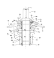
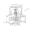
図1及び図2を参照して、本発明の第一実施形態に係る船用立軸遠心ポンプ50を説明する。図1は、本発明の第一実施形態に係る船用立軸遠心ポンプ50を示す断面図である。図2は、図1に示す船用立軸遠心ポンプ50の要部を示す拡大断面図である。なお、各図はシャフト13の中心軸Lにおける直角断面図である。
(First embodiment)
With reference to FIG.1 and FIG.2, the vertical shaft
この船用立軸遠心ポンプ50は、主にモーターカップリング11と、カップリングスペーサ59と、ポンプカップリング12と、シャフト13と、メカニカルシール14と、ラインベアリング15と、インペラ16と、ケーシング17と、ケーシングカバー51と、スタフィングボックス52とを備えるものであり、特にカップリングスペーサ59と、ケーシングカバー51の形状に特徴がある。
This vertical shaft
モーターカップリング11は、モーターMの下方に連結して配置される。これは、モーターカップリング11の下方にある、カップリングスペーサ59にモーターMの回転軸の回転を伝えるものであり、モーターMの回転軸の回転にともなって回転する。
The
カップリングスペーサ59は、モーターカップリング11の下方に連結具Tにより連結され配置される。これは、モーターカップリング11を介して伝わるモーターMの回転軸の回転を、カップリングスペーサ59よりも下方にある、ポンプカップリング12に伝えるものであり、モーターカップリング11の回転にともなって回転する。
ここで、重量物であるモーターMを取外すことなく、カップリングスペーサ59を取外した後に形成される隙間からポンプカップリング12、メカニカルシール14およびラインベアリング15を取出すことができるように、カップリングスペーサ59の上下方向の長さは、ポンプカップリング12、メカニカルシール14およびラインベアリング15のそれぞれの上下方向の長さよりも長くなっている。しかし、シャフト13をその隙間から取出す従来例に比べ短く、僅か165mm程度である。
The
Here, the coupling spacer can be removed so that the
ポンプカップリング12は、モーターカップリング11の下方に連結具Tにより連結され配置される。これは、カップリングスペーサ59等を介して伝わるモーターMの回転軸の回転を、ポンプカップリング12よりも下方にあるシャフト13に伝えるものであり、カップリングスペーサ59の回転にともなって回転する。
その上下方向の長さは、カップリングスペーサ59の上下方向の長さよりも短い。
The
The vertical length is shorter than the vertical length of the
シャフト13は、ポンプカップリング12の下方にシャフト連結具(図示しない)により連結され、鉛直方向に延びる。これは、ポンプカップリング12等を介して伝わるモーターMの回転軸の回転を、インペラ16に伝えるものであり、ポンプカップリング12の回転にともなって回転する。
この回転時には少なからず振動や偏心があり、長期間使用を続ければシャフト13の外表面は磨耗する。シャフト13の交換は労力とコストがかかるため、実際にはシャフト13の外周には円筒状のスリーブ20が備えられている。スリーブ20の内側はシャフト13の外表面と密着し、スリーブ20はシャフト13とともに回転する。よって、磨耗はスリーブ20の外表面のみに抑えられる。スリーブ20の交換はシャフト13の交換よりも容易且つ安価であるので、このような手法が取られている。
また、ポンプカップリング12がシャフト13に連結されているときには、ポンプカップリング12の上端とシャフト13の上端は、船用立軸遠心ポンプ50に対して略等しい高さとなる。
The
During this rotation, there is a considerable amount of vibration and eccentricity, and the outer surface of the
When the
メカニカルシール14は、ポンプカップリング12の下方に設けられ、スリーブ20間を密封する軸封装置の一種であり、図2に示すように、主にフローティングシート14a、シールリング14b、第一パッキン14c、第二パッキン14d、スプリング14e、ストッパーリング14f、セットスクリュー14gよりなる。メカニカルシール14の上下方向の長さは、カップリングスペーサ59の上下方向の長さよりも短い。
船用立軸遠心ポンプ50運転中には、船用立軸遠心ポンプ50内の圧力は大気圧よりも高くなり、内部の液体はポンプの外に漏れ出ようとするので、メカニカルシール14が必要となる。
The
During operation of the ship vertical shaft
このメカニカルシール14の部品の中で、最重要部品はフローティングシート14aとシールリング14bである。シャフト13回転時において、フローティングシート14aはメカカバー53に固定されて動かないのに対し、シールリング14bはスリーブ20に固定されているので、スリーブ20やシャフト13とともに回転する。
フローティングシート14aとシールリング14bとの接触面は、それぞれ精密に仕上げられており、フローティングシート14aとシールリング14bの間には、シールリング14bは回転可能であるが液体は漏れない極めて微小な隙間が設定されている。
Among the parts of the
The contact surfaces of the floating
第一パッキン14cは、シールリング14bとスリーブ20との間の漏れを防止する。第一パッキン14cは合成ゴムその他の弾性体よりなり、シャフト13の振動や偏心にも応じて、スリーブ20との密着を保つ。
第二パッキン14dは、フローティングシート14aとメカカバー53との間の漏れを防止する。第一パッキン14c同様、合成ゴムその他の弾性体よりなる。
The
The
スプリング14eは、一定の圧力でシールリング14bをフローティングシート14a方向に押し、フローティングシート14aとシールリング14bの接触を良好に保つ。
ストッパーリング14fは、メカニカルシール14のシャフト13に対する上下方向の位置を決めるものであり、ストッパーリング14fで決定される位置より下方にはメカニカルシール14は下がらない。
The
The
セットスクリュー14gは、メカニカルシール14の下部位置にあるストッパーリング14fをスリーブ20に対して固定するものであり、シャフト13に対して垂直に延びる。外形は、ネジ頭がなく、外側全てにネジ山が切られており、通常は六角レンチにてネジ締めを行う。
The
ラインベアリング15は、シャフト13の軸受けとなるものであり、上下方向の長さは、カップリングスペーサ59の上下方向の長さよりも短い。
そして、メカニカルシール14の下方に配置され、ケーシングカバー51に形成された凹部51aの側壁下部51bとスリーブ20との間に対して、上方から差し込まれる。
The
And it is arrange | positioned from the upper direction with respect to the
インペラ16は、ラインベアリング15の下方で、シャフト13の下部に連結された羽根の付いた回転体であり、羽根車とも呼ばれる。シャフト13等を介してモーターMの回転軸の回転により、ケーシング17の中心部で高速回転し、ケーシング17内の液体に遠心力を加え、昇圧する。
The
ケーシング17は、インペラ16とラインベアリング15を包含する船用立軸遠心ポンプ50の本体であり、上方に開口部が形成されている。
そして、インペラ16によって送り出された液体の圧力を上げて、揚水するものである。
The
And the pressure of the liquid sent out by the
ケーシングカバー51は、ケーシング17の開口部を覆う蓋であり、ケーシング17とともにインペラ16によって送り出された液体の圧力を上げるものである。
ケーシングカバー51の中央部には、シャフト13が貫通する孔を有する断面略矩形状の凹部51aが形成される。また、凹部51aの側壁下部51bとスリーブ20との隙間には、上部にラインベアリングカバー58が取付けられたラインベアリング15を上から差し込むことが可能であり、且つ差し込まれたラインベアリング15が落下しないように、凹部51aの下部にはストッパー51dが形成されている。
The
A
ここで、ラインベアリングカバー58とラインベアリング15は第三ボルト56で、ラインベアリングカバー58とケーシングカバー51は第四ボルト57で、それぞれ固定される。
このように、ケーシングカバー51はラインベアリング15が差し込まれた状態でラインベアリング15を支持する。
加えて、側壁上部51cとスリーブ20との間に、セットスクリュー14gを取外すためのL型六角レンチを差し込んで作業可能となる程度の側壁上部51cが設けられ、この凹部51aの側壁上部51cの内径S2は、側壁下部51bの内径S1よりも大きく形成されている。
Here, the
Thus, the
In addition, an L-shaped hexagon wrench for removing the
スタフィングボックス52は、ケーシングカバー51に形成された凹部51aを上方から覆う蓋であり、中央部には、シャフト13が貫通する孔が形成されている。そして、第二ボルト55によりケーシングカバー51に固定されている。
なお、スタフィングボックス52とメカニカルシール14との間には隙間があるので、その隙間を、第二パッキン14dを介してメカカバー53が蓋をし、第一ボルト54にてメカカバー53はスタフィングボックス52に固定される。
The
Since there is a gap between the
このように構成された船用立軸遠心ポンプ50においてモーターMの電源が入ると、それにともなって連結されたモーターカップリング11、カップリングスペーサ59、ポンプカップリング12、シャフト13、メカニカルシール14の下部(シールリング14bより下方の部材)、インペラ16が高速回転し、揚水する。
When the power of the motor M is turned on in the vertical shaft
以下、この船用立軸遠心ポンプ50において、メカニカルシール14及びラインベアリング15の交換の手順を説明する。
Hereinafter, the procedure for exchanging the
初めに、二つの連結具Tを取外し、カップリングスペーサ59を取外す。
次に、ポンプカップリング12とシャフト13を連結しているシャフト連結具(図示しない)を取外し、ポンプカップリング12をシャフト13に沿って上方に引き上げ、シャフト13から抜く。その後、カップリングスペーサ59の取外しによって形成された隙間からポンプカップリング12を外部に取出す。ポンプカップリング12を取出した後の要部を示す図が図2である。
First, the two connecting tools T are removed, and the
Next, a shaft coupler (not shown) that connects the
そして、メカカバー53とスタフィングボックス52とを結合している第一ボルト54を外し、メカカバー53をスタフィングボックス52から外して上方に引き上げてシャフト13から抜く。このとき、フローティングシート14aと第二パッキン14dがメカカバー53と一緒に外れる。メカカバー53もポンプカップリング12同様、カップリングスペーサ59があった空間から、外部に取出す。なお、スタフィングボックス52とメカカバー53は一体構造でもよい。
Then, the
次に、スタフィングボックス52とケーシングカバー51とを結合している第二ボルト55を外し、スタフィングボックス52をケーシングカバー51から外して、シャフト13の上方に取外す。
Next, the
次に、凹部51aの側壁上部51cとスリーブ20との隙間にL型六角レンチを差し込んでセットスクリュー14gを緩める。ケーシングカバー51に形成された凹部51aの側壁上部51cの内径S2は、側壁下部51bの内径S1よりも大きく形成されているので、ここにL型六角レンチを差し込むことができる。
Next, an L-shaped hexagon wrench is inserted into the gap between the
セットスクリュー14gが緩んだ後、シャフト13およびインペラ16をケーシング17から取出すことなく、メカニカルシール14の残りの部品であるシールリング14b、スプリング14e、及びストッパーリング14fをケーシング17の上方に取出し、シャフト13から外す。そしてカップリングスペーサ59を取外すことによって形成された隙間からそれらの部品を外部に取外す。
After the
ラインベアリング15を交換する必要が無い場合には、この時点で清浄なウエスに洗浄液を塗布してスリーブ20外表面を清掃した後、新しいメカニカルシール14を組み込む。組み込む順番は、分解のときと逆の順序で行う。
If it is not necessary to replace the line bearing 15, a cleaning liquid is applied to a clean waste cloth at this time to clean the outer surface of the
ラインベアリング15を交換する必要がある場合は、メカニカルシール14を取出した後、そのまま次の作業に進む。
If the line bearing 15 needs to be replaced, the
ラインベアリング15の交換は、まず、ラインベアリングカバー58とケーシングカバー51とを結合している第四ボルト57を外し、ラインベアリングカバー58とラインベアリング15を一体で上方に取出し、シャフト13から外す。そして、カップリングスペーサ59を取外すことによって形成された隙間から外部に取外す。
To replace the line bearing 15, first, the
ここで、ラインベアリングカバー58とラインベアリング15は第三ボルト56で結合されているので、一体で引き抜くことができる。
この場合、ラインベアリングカバー58に加工してあるネジ穴に、別の長いボルトを取りつけて、そのボルトを上方に引き上げれば、ラインベアリング15の引き抜きはより簡単になる。
Here, since the
In this case, if another long bolt is attached to the screw hole processed in the
ラインベアリング15を取外した後、清浄なウエスに洗浄液を塗布してスリーブ20外表面を清掃した後、新しいラインベアリング15を組み込む。組み込む順番は、分解のときと逆の手順で行う。
After removing the line bearing 15, the cleaning liquid is applied to a clean waste to clean the outer surface of the
なお、ラインベアリング15は、ケーシングカバー51に形成された凹部51aの側壁下部51bに対して上方から差し込まれるようにしたが、これに限られるものではなく、図3のケーシングカバー61のように、ラインベアリング15が下方から差し込まれるようにしてもよい。
The
つまり、図3のケーシングカバー61にも、中央部にシャフト13が貫通する孔が形成された断面略矩形状の凹部61aが形成され、凹部61aの側壁下部61bとスリーブ20との隙間には、ラインベアリング15を差し込むことが可能である。ここで、図2のものとは違い、凹部61aの側壁下部61bの上端がストッパー61dとなっており、下から差し込まれたラインベアリング15がそれ以上上昇しないようになっている。そして、差し込まれたラインベアリング15が落下しないように、下方からラインベアリングカバー62で蓋をする。
なお、図2のものと同様に、凹部61aの側壁上部61cの内径K2は、側壁下部61bの内径K1よりも大きく形成されている。
That is, the
2, the inner diameter K2 of the
このようにラインベアリング15が下方から差し込まれる構造では、ラインベアリング15を交換するためにはケーシングカバー61を取外す必要があるが、より交換頻度の高いメカニカルシール14は、スタフィングボックス52を取外すだけで交換できるので、従来の船用立軸遠心ポンプ10よりも有効である。
In such a structure in which the line bearing 15 is inserted from below, it is necessary to remove the
(第二実施形態)
次に図4を参照して、本発明の第二実施形態に係る船用立軸遠心ポンプ50を説明する。図4は、本発明の第二実施形態に係る船用立軸遠心ポンプ50の要部を示す拡大断面図である。なお、図4はシャフト13の中心軸Lにおける直角断面図である。また、第一実施形態と同一部分には同一符号を付した。
(Second embodiment)
Next, with reference to FIG. 4, the vertical shaft
第二実施形態の第一実施形態との違いは、軸封装置としてグランドパッキン72を使用していること、それにともなってスタフィングボックスの形状が変更されていること、メカカバー53がグランドパッキンカバー73に代わったことのみであり、その他の構成要素は全て第一実施形態と同一である。
以下、第一実施形態とは違う構造である、グランドパッキン72に関わる部分について主に説明する。
The difference of the second embodiment from the first embodiment is that a gland packing 72 is used as a shaft seal device, the shape of the stuffing box is changed accordingly, and the
Hereinafter, a part related to the gland packing 72, which is a structure different from that of the first embodiment, will be mainly described.
スタフィングボックス71は、ケーシングカバー51の凹部51aを上方から覆う蓋である点に関しては第一実施形態と同じである。
第一実施形態のスタフィングボックス52との違いは、中央部にシャフト13が貫通する孔が形成された断面略矩形状の凹部71aが形成され、このスタフィングボックス71の凹部71aの側壁とスリーブ20との間にグランドパッキン72が差し込まれることである。スタフィングボックス71の凹部71aには、グランドパッキン72が落下しないように、底部71bが設けられている。
The
The difference from the
グランドパッキン72は、一箇所が切れているリング状のパッキンであり、先に述べたように、スタフィングボックス71の凹部71aに詰め込まれる。
ここで、グランドパッキン72の上端がスタフィングボックス71の凹部71aよりも上方に出ないように、グランドパッキン72はスタフィングボックス71の凹部71aに詰め込まれる。
The gland packing 72 is a ring-shaped packing that is cut at one place, and is packed in the
Here, the gland packing 72 is packed in the
グランドパッキンカバー73は、スタフィングボックス71の凹部71aの蓋であり、半割り構造となっている。グランドパッキンカバー73中央部の外形はスタフィングボックス71の凹部71aと略相似形であり、スタフィングボックス71の凹部71aに挿入可能である。
そして、グランドパッキン72挿入後に、上方からグランドパッキン72を押さえつけ、押さえつけたまま、その位置に固定されるものである。
The
Then, after the gland packing 72 is inserted, the gland packing 72 is pressed from above, and the gland packing 72 is fixed in that position while being pressed.
このようにグランドパッキンカバー73でグランドパッキン72を上方から押さえつけることによって、グランドパッキン72は横方向に潰れ、スリーブ20との間を密封することができる。
ただし、グランドパッキンカバー73の締め付けは、シャフト13が回転可能な程度に緩く、且つ液体が漏れない程度にきつく行わなければならない。
By pressing the gland packing 72 from above with the
However, the
以下、このような構造のグランドパッキン72の交換の手順を説明する。 The procedure for exchanging the gland packing 72 having such a structure will be described below.
まず、第一実施形態と同じ手順で、ポンプカップリング12の取外しまで行う。
First, the same procedure as in the first embodiment is performed until the
次に、グランドパッキンカバー73の締め付けを解除して、シャフト13の上方に引き抜く。そして、カップリングスペーサ59を取外すことによって形成された隙間から外部に取外す。
Next, the tightening of the
次に、グランドパッキン72を上方に引き上げて、シャフト13から外す。グランドパッキン72は、グランドパッキンカバー73の締め付けのみで固定されており、なおかつ切断されたリング形状であるので、グランドパッキンカバー73が外れれば、容易に取出すことができる。
Next, the gland packing 72 is pulled upward and removed from the
次のスタフィングボックス71の取外しは第一実施形態と同様であり、スタフィングボックス71とケーシングカバー51とを結合している第二ボルト55を外し、スタフィングボックス71をケーシングカバー51から外して、シャフト13の上方に取外す。
The next removal of the
そして、次に行うラインベアリング15の取外しは、第一実施形態と同様である。 And the removal of the line bearing 15 performed next is the same as that of 1st embodiment.
このように、軸封装置がグランドパッキン72であっても、モーターM、シャフト13、インペラ16を取外すことなく、交換することができる。
Thus, even if the shaft seal device is the gland packing 72, it can be replaced without removing the motor M, the
なお、シャフト13にスリーブ20が備えられているものに限られるものではなく、スリーブ20がなく、スリーブ20の厚み分だけ半径の大きいシャフト13であってもよい。
この場合、第一、第二実施形態における「スリーブ20」の文言は、「シャフト13」と読み替えるだけで足りる。
Note that the
In this case, the term “
また、スタフィングボックス71は、一体型の、中央にシャフト13が貫通する孔が形成されたものとしたが、これに限られるものではなく、半割り構造としてもよい。
In addition, the
また、グランドパッキンカバー73は一体構造でも半割り構造のどちらでもよいが、半割り構造の場合には締め付けを解除した後、分解してシャフト13から外しても構わない。この場合は、ポンプカップリング12をシャフト13から外さなくてもグランドパッキン72を交換することができる。
Further, the
また、カップリングスペーサ59の上下方向の長さを、軸封装置14,72、ポンプカップリング12、及びラインベアリング15の上下方向のそれぞれの長さより長くしたが、ラインベアリング15をケーシングカバー61の下から差し込む構造の船用立軸遠心ポンプ50においては、カップリングスペーサ59の上下方向の長さは、軸封装置14,72とポンプカップリング12の上下方向のそれぞれの長さよりも長ければ足りる。
Further, the vertical length of the
また、取外し用工具はL型六角レンチとしたが、これに限られるものではなく、軸封装置14,72を取出すことができる工具であればよい。
Moreover, although the removal tool is an L-shaped hexagon wrench, it is not limited to this, and any tool that can take out the
10 船用立軸遠心ポンプ
11 モーターカップリング
12 ポンプカップリング
13 シャフト
14 メカニカルシール
14a フローティングシート
14b シールリング
14c 第一パッキン
14d 第二パッキン
14e スプリング
14f ストッパーリング
14g セットスクリュー
15 ラインベアリング
16 インペラ
17 ケーシング
18 ケーシングカバー
19 カップリングスペーサ
20 スリーブ
50 船用立軸遠心ポンプ
51 ケーシングカバー
51a 凹部
51b 側壁下部
51c 側壁上部
51d ストッパー
52 スタフィングボックス
53 メカカバー
54 第一ボルト
55 第二ボルト
56 第三ボルト
57 第四ボルト
58 ラインベアリングカバー
59 カップリングスペーサ
61 ケーシングカバー
61a 凹部
61b 側壁下部
61c 側壁上部
61d ストッパー
62 ラインベアリングカバー
71 スタフィングボックス
71a 凹部
71b 底部
72 グランドパッキン
73 グランドパッキンカバー
K1 ケーシングカバーの凹部下部の内径
K2 ケーシングカバーの凹部上部の内径
L シャフトの中心軸
M モーター
S1 ケーシングカバーの凹部下部の内径
S2 ケーシングカバーの凹部上部の内径
T 連結具
10 Ship Vertical
Claims (6)
前記モーターカップリングの下方に配置されたポンプカップリングと、
前記ポンプカップリングの下方に連結された鉛直方向に延びるシャフトと、
前記ポンプカップリングの下方に設けられ、前記シャフト間を密封し、少なくとも下部位置が前記シャフトに固定されてなる軸封装置と、
前記軸封装置の下方に配置され、前記シャフトの軸受けとなるラインベアリングと、
前記ラインベアリングの下方で、前記シャフトの下部に連結されたインペラと、
前記インペラと前記ラインベアリングを包含し、上方に開口部が形成されたケーシングと、
前記ケーシングの開口部を覆う蓋となるとともに、前記シャフトが貫通する孔が形成された断面略矩形状の凹部が形成され、しかも前記凹部の側壁下部と前記シャフトとの間に前記ラインベアリングが差し込まれた状態で前記ラインベアリングを支持するケーシングカバーと、を備える船用立軸遠心ポンプにおいて、
前記ケーシングカバーに形成された凹部を上方から覆う蓋となるスタフィングボックスと、
前記モーターカップリングと前記ポンプカップリングの間に、上下方向の長さが前記ポンプカップリングおよび軸封装置の上下方向の長さよりも長く、前記モーターカップリングと前記ポンプカップリングにそれぞれ連結されたカップリングスペーサと、を備え、
前記ケーシングカバーに形成された凹部の側壁上部の内径を、前記側壁下部の内径よりも大きく形成したことを特徴とする船用立軸遠心ポンプ。 A motor coupling coupled below the motor;
A pump coupling disposed below the motor coupling;
A vertically extending shaft coupled below the pump coupling;
A shaft seal device provided below the pump coupling, sealing between the shafts, and at least a lower position being fixed to the shaft;
A line bearing disposed below the shaft seal device and serving as a bearing for the shaft;
An impeller coupled to a lower portion of the shaft below the line bearing;
A casing including the impeller and the line bearing and having an opening formed above;
A recess covering the opening of the casing and having a substantially rectangular cross section in which a hole through which the shaft passes is formed, and the line bearing is inserted between the lower portion of the side wall of the recess and the shaft. In a vertical shaft centrifugal pump for a ship provided with a casing cover that supports the line bearing in the
A stuffing box serving as a lid for covering the concave portion formed in the casing cover from above;
Between the motor coupling and the pump coupling, the length in the vertical direction is longer than the length in the vertical direction of the pump coupling and the shaft seal device, and is connected to the motor coupling and the pump coupling, respectively. A coupling spacer;
A marine vertical shaft centrifugal pump characterized in that the inner diameter of the upper part of the side wall of the recess formed in the casing cover is larger than the inner diameter of the lower part of the side wall.
前記モーターカップリングの下方に配置されたポンプカップリングと、
前記ポンプカップリングの下方に連結された鉛直方向に延びるシャフトと、
前記ポンプカップリングの下方に設けられ、前記シャフト間を密封し、少なくとも下部位置が前記シャフトに固定されてなる軸封装置と、
前記軸封装置の下方に配置され、前記シャフトの軸受けとなるラインベアリングと、
前記ラインベアリングの下方で、前記シャフトの下部に連結されたインペラと、
前記インペラと前記ラインベアリングを包含し、上方に開口部が形成されたケーシングと、
前記ケーシングの開口部を覆う蓋となるとともに、前記シャフトが貫通する孔が形成された断面略矩形状の凹部が形成され、しかも前記凹部の側壁下部と前記シャフトとの間に前記ラインベアリングが差し込まれた状態で前記ラインベアリングを支持するケーシングカバーと、を備える船用立軸遠心ポンプの部品交換方法において、
前記ケーシングカバーに形成された凹部を上方から覆う蓋となるスタフィングボックスと、
前記モーターカップリングと前記ポンプカップリングの間に、上下方向の長さが前記ポンプカップリングおよび前記軸封装置の上下方向の長さよりも長く、前記モーターカップリングと前記ポンプカップリングにそれぞれ連結されたカップリングスペーサと、を備えるとともに、
前記ケーシングカバーに形成された凹部の側壁上部の内径を、前記側壁下部の内径よりも大きく形成して、前記カップリングスペーサを取外し、その取外しによって形成された隙間から前記ポンプカップリングを取外し、前記スタフィングボックスを上方に取外した後、前記凹部の側壁上部と前記シャフトとの隙間から取外し用工具を差し込んで、前記シャフトおよび前記インペラを前記ケーシングから取出すことなく、前記軸封装置を前記ケーシングの上方に取出し、前記カップリングスペーサを取外すことによって形成される隙間から外部に取外すようにしたことを特徴とする船用立軸遠心ポンプの部品交換方法。 A motor coupling coupled below the motor;
A pump coupling disposed below the motor coupling;
A vertically extending shaft coupled below the pump coupling;
A shaft seal device provided below the pump coupling, sealing between the shafts, and at least a lower position being fixed to the shaft;
A line bearing disposed below the shaft seal device and serving as a bearing for the shaft;
An impeller coupled to a lower portion of the shaft below the line bearing;
A casing including the impeller and the line bearing and having an opening formed above;
A recess covering the opening of the casing and having a substantially rectangular cross section with a hole through which the shaft passes is formed, and the line bearing is inserted between the lower portion of the side wall of the recess and the shaft. In a part replacement method for a marine vertical shaft centrifugal pump comprising a casing cover that supports the line bearing in a state of being
A stuffing box serving as a lid for covering the concave portion formed in the casing cover from above;
Between the motor coupling and the pump coupling, the length in the vertical direction is longer than the length in the vertical direction of the pump coupling and the shaft seal device, and is connected to the motor coupling and the pump coupling, respectively. A coupling spacer, and
The inner diameter of the upper part of the side wall of the recess formed in the casing cover is made larger than the inner diameter of the lower part of the side wall, the coupling spacer is removed, the pump coupling is removed from the gap formed by the removal, After removing the stuffing box upward, the removal tool is inserted through the gap between the upper portion of the side wall of the recess and the shaft, and the shaft seal device is removed from the casing without removing the shaft and the impeller from the casing. A method for replacing parts of a vertical shaft centrifugal pump for a ship, wherein the parts are removed upward from a gap formed by removing the coupling spacer.
Priority Applications (1)
| Application Number | Priority Date | Filing Date | Title |
|---|---|---|---|
| JP2008227871A JP4892529B2 (en) | 2008-09-05 | 2008-09-05 | Ship vertical shaft centrifugal pump and parts replacement method for ship vertical shaft centrifugal pump |
Applications Claiming Priority (1)
| Application Number | Priority Date | Filing Date | Title |
|---|---|---|---|
| JP2008227871A JP4892529B2 (en) | 2008-09-05 | 2008-09-05 | Ship vertical shaft centrifugal pump and parts replacement method for ship vertical shaft centrifugal pump |
Publications (2)
| Publication Number | Publication Date |
|---|---|
| JP2010059901A true JP2010059901A (en) | 2010-03-18 |
| JP4892529B2 JP4892529B2 (en) | 2012-03-07 |
Family
ID=42186960
Family Applications (1)
| Application Number | Title | Priority Date | Filing Date |
|---|---|---|---|
| JP2008227871A Active JP4892529B2 (en) | 2008-09-05 | 2008-09-05 | Ship vertical shaft centrifugal pump and parts replacement method for ship vertical shaft centrifugal pump |
Country Status (1)
| Country | Link |
|---|---|
| JP (1) | JP4892529B2 (en) |
Cited By (8)
| Publication number | Priority date | Publication date | Assignee | Title |
|---|---|---|---|---|
| JP2013053710A (en) * | 2011-09-06 | 2013-03-21 | Chugoku Electric Power Co Inc:The | Coupling structure and electric pump |
| EP3006741A1 (en) * | 2014-10-09 | 2016-04-13 | Ebara Corporation | Turbopump with shaft coupling |
| JP2016121673A (en) * | 2014-10-09 | 2016-07-07 | 株式会社荏原製作所 | Turbo pump |
| JP2017031949A (en) * | 2015-08-05 | 2017-02-09 | テラル株式会社 | pump |
| JP2017067039A (en) * | 2015-10-01 | 2017-04-06 | 株式会社荏原製作所 | Turbo pump |
| JP2017122408A (en) * | 2016-01-07 | 2017-07-13 | Kawamoto Gec株式会社 | Pump casing and pump device |
| KR101968192B1 (en) * | 2018-12-07 | 2019-04-11 | 박강용 | A Upright Turbine Pump |
| KR101968176B1 (en) * | 2018-09-20 | 2019-04-11 | 박강용 | A Mechanical Seal Repair Coupling Device of a Pump |
Families Citing this family (1)
| Publication number | Priority date | Publication date | Assignee | Title |
|---|---|---|---|---|
| CN106438488A (en) * | 2016-12-03 | 2017-02-22 | 申晓丽 | Vertical fire pump |
Citations (4)
| Publication number | Priority date | Publication date | Assignee | Title |
|---|---|---|---|---|
| JPS5463202A (en) * | 1978-09-29 | 1979-05-22 | Toshiba Corp | Manufacture of stator of revolving electrical machine |
| JPS5470101A (en) * | 1977-11-16 | 1979-06-05 | Gakken Co Ltd | Method of making plate by facsimile plate making machine |
| JPS59138794A (en) * | 1983-01-28 | 1984-08-09 | Ebara Corp | Circulating pump of high temperature liquid tank |
| JPS60153895A (en) * | 1984-01-22 | 1985-08-13 | 内海 正文 | Main yarn sewing machine |
-
2008
- 2008-09-05 JP JP2008227871A patent/JP4892529B2/en active Active
Patent Citations (4)
| Publication number | Priority date | Publication date | Assignee | Title |
|---|---|---|---|---|
| JPS5470101A (en) * | 1977-11-16 | 1979-06-05 | Gakken Co Ltd | Method of making plate by facsimile plate making machine |
| JPS5463202A (en) * | 1978-09-29 | 1979-05-22 | Toshiba Corp | Manufacture of stator of revolving electrical machine |
| JPS59138794A (en) * | 1983-01-28 | 1984-08-09 | Ebara Corp | Circulating pump of high temperature liquid tank |
| JPS60153895A (en) * | 1984-01-22 | 1985-08-13 | 内海 正文 | Main yarn sewing machine |
Cited By (9)
| Publication number | Priority date | Publication date | Assignee | Title |
|---|---|---|---|---|
| JP2013053710A (en) * | 2011-09-06 | 2013-03-21 | Chugoku Electric Power Co Inc:The | Coupling structure and electric pump |
| EP3006741A1 (en) * | 2014-10-09 | 2016-04-13 | Ebara Corporation | Turbopump with shaft coupling |
| CN105508283A (en) * | 2014-10-09 | 2016-04-20 | 株式会社荏原制作所 | A turbopump |
| JP2016121673A (en) * | 2014-10-09 | 2016-07-07 | 株式会社荏原製作所 | Turbo pump |
| JP2017031949A (en) * | 2015-08-05 | 2017-02-09 | テラル株式会社 | pump |
| JP2017067039A (en) * | 2015-10-01 | 2017-04-06 | 株式会社荏原製作所 | Turbo pump |
| JP2017122408A (en) * | 2016-01-07 | 2017-07-13 | Kawamoto Gec株式会社 | Pump casing and pump device |
| KR101968176B1 (en) * | 2018-09-20 | 2019-04-11 | 박강용 | A Mechanical Seal Repair Coupling Device of a Pump |
| KR101968192B1 (en) * | 2018-12-07 | 2019-04-11 | 박강용 | A Upright Turbine Pump |
Also Published As
| Publication number | Publication date |
|---|---|
| JP4892529B2 (en) | 2012-03-07 |
Similar Documents
| Publication | Publication Date | Title |
|---|---|---|
| JP4892529B2 (en) | Ship vertical shaft centrifugal pump and parts replacement method for ship vertical shaft centrifugal pump | |
| JP5014177B2 (en) | Counter-rotating propeller unit and its assembling method, transportation method and mounting method on the ship | |
| EP2279114B1 (en) | Propulsion and bearing arrangement for a ship and bearing arrangement | |
| US2911240A (en) | Sealing means for receptacle shaft opening | |
| JP4908482B2 (en) | Oil leakage prevention structure for hollow output shaft reducer | |
| JP2009000661A (en) | Agitation apparatus and reaction tank using the same | |
| CN101487471A (en) | Hydraulic driving centrifugal liquid cargo pump | |
| US9488180B2 (en) | Efficient and reliable subsea compression system | |
| JP5671334B2 (en) | Vertical shaft pump | |
| KR101438253B1 (en) | Multistage insert type sleeve configurations Radial Shaft Seal Unit | |
| JP2007229668A (en) | Rotary shaft for flocculator and connector therefor | |
| FI123875B (en) | Arrangement for sealing propeller shaft | |
| US3557744A (en) | Aft structures of marine vessels | |
| KR20130036405A (en) | Fixed fluid offloading apparatus | |
| JP5344751B2 (en) | Vertical shaft pump | |
| CN109578590A (en) | A kind of hydraulic propeller axis mechanical seal | |
| KR102386314B1 (en) | Rope cutting device for ship | |
| JP6389148B2 (en) | pump | |
| CN111661291B (en) | Sealing device for pod propeller | |
| JP3950172B2 (en) | Hub assembly for water jet propulsion unit | |
| WO2016009977A1 (en) | Vertical shaft pump | |
| JP2004535307A (en) | Drive for drill stem | |
| JPH0627519Y2 (en) | Counter-rotating shaft seal device | |
| US20100194053A1 (en) | Gasket and packing panel assembly for trunnion/shaft | |
| JP3851492B2 (en) | underwater pump |
Legal Events
| Date | Code | Title | Description |
|---|---|---|---|
| A977 | Report on retrieval |
Free format text: JAPANESE INTERMEDIATE CODE: A971007 Effective date: 20110803 |
|
| A131 | Notification of reasons for refusal |
Free format text: JAPANESE INTERMEDIATE CODE: A131 Effective date: 20110816 |
|
| A521 | Request for written amendment filed |
Free format text: JAPANESE INTERMEDIATE CODE: A523 Effective date: 20110929 |
|
| RD02 | Notification of acceptance of power of attorney |
Free format text: JAPANESE INTERMEDIATE CODE: A7422 Effective date: 20110929 |
|
| A521 | Request for written amendment filed |
Free format text: JAPANESE INTERMEDIATE CODE: A523 Effective date: 20110930 |
|
| TRDD | Decision of grant or rejection written | ||
| A01 | Written decision to grant a patent or to grant a registration (utility model) |
Free format text: JAPANESE INTERMEDIATE CODE: A01 Effective date: 20111213 |
|
| A01 | Written decision to grant a patent or to grant a registration (utility model) |
Free format text: JAPANESE INTERMEDIATE CODE: A01 |
|
| A61 | First payment of annual fees (during grant procedure) |
Free format text: JAPANESE INTERMEDIATE CODE: A61 Effective date: 20111219 |
|
| R150 | Certificate of patent or registration of utility model |
Free format text: JAPANESE INTERMEDIATE CODE: R150 Ref document number: 4892529 Country of ref document: JP Free format text: JAPANESE INTERMEDIATE CODE: R150 |
|
| FPAY | Renewal fee payment (event date is renewal date of database) |
Free format text: PAYMENT UNTIL: 20141222 Year of fee payment: 3 |
|
| R250 | Receipt of annual fees |
Free format text: JAPANESE INTERMEDIATE CODE: R250 |
|
| R250 | Receipt of annual fees |
Free format text: JAPANESE INTERMEDIATE CODE: R250 |
|
| R250 | Receipt of annual fees |
Free format text: JAPANESE INTERMEDIATE CODE: R250 |
|
| R250 | Receipt of annual fees |
Free format text: JAPANESE INTERMEDIATE CODE: R250 |
|
| R250 | Receipt of annual fees |
Free format text: JAPANESE INTERMEDIATE CODE: R250 |