JP2010058415A - Transfer pattern forming method and transfer pattern forming blanket - Google Patents
Transfer pattern forming method and transfer pattern forming blanket Download PDFInfo
- Publication number
- JP2010058415A JP2010058415A JP2008227759A JP2008227759A JP2010058415A JP 2010058415 A JP2010058415 A JP 2010058415A JP 2008227759 A JP2008227759 A JP 2008227759A JP 2008227759 A JP2008227759 A JP 2008227759A JP 2010058415 A JP2010058415 A JP 2010058415A
- Authority
- JP
- Japan
- Prior art keywords
- blanket
- base material
- substrate
- pattern
- transfer
- Prior art date
- Legal status (The legal status is an assumption and is not a legal conclusion. Google has not performed a legal analysis and makes no representation as to the accuracy of the status listed.)
- Granted
Links
Images


Landscapes
- Printing Methods (AREA)
- Printing Plates And Materials Therefor (AREA)
Abstract
Description
本発明は、転写パターン形成方法および転写パターン形成用ブランケットに関する。詳しくは、ブランケットに塗布したインクを版によって形成するパターンのみ残すように形成し、これを基板に転写する転写パターン形成方法および転写パターン形成用ブランケットに関する。 The present invention relates to a transfer pattern forming method and a transfer pattern forming blanket. More specifically, the present invention relates to a transfer pattern forming method and a transfer pattern forming blanket in which an ink applied to a blanket is formed so as to leave only a pattern formed by a plate and transferred to a substrate.
反転オフセット印刷を用いたパターン形成方法としては、特許文献1〜3に示される技術が開示されている。いずれも、インクを塗布したブランケットとパターンに対応した凹部を有する版とを加圧接触させ、ブランケット側にパターンに対応したインクのみを残し、これを基板に加圧接触させることで、ブランケット側に残ったインクのパターンを基板に転写させている。
As a pattern forming method using reverse offset printing, techniques disclosed in
しかしながら、ブランケットから基板へインクのパターンを転写する際、窪み形状を有する基板では、ブランケットの加圧接触時にブランケットの弾性変形量が基板の窪みの深さより少ないと、インクのパターンの転写不良が生じる。一方、ブランケットの弾性変形部分の厚さを増加すれば基板の窪みの深さまで到達できるが、ブランケットと版とを加圧接触する際、版の凹部の底にブランケットの弾性変形部分が到達してしまい、ブランケット側でのインク転写の不良が生じる。 However, when the ink pattern is transferred from the blanket to the substrate, if the substrate has a depression shape and the amount of elastic deformation of the blanket is smaller than the depth of the depression of the substrate when the blanket is in pressure contact, the ink pattern transfer failure occurs. . On the other hand, if the thickness of the elastic deformation portion of the blanket is increased, the depth of the substrate can be reached, but when the blanket and the plate are brought into pressure contact, the elastic deformation portion of the blanket reaches the bottom of the depression of the plate. As a result, ink transfer failure occurs on the blanket side.
本発明は、窪みを有する基板にブランケットからインクのパターンを転写するパターンの形成において、ブランケットへのパターン転写と基板へのパターン転写との両方で良好な転写を行うことを目的とする。 An object of the present invention is to perform good transfer both in the pattern transfer to the blanket and the pattern transfer to the substrate in the formation of the pattern for transferring the ink pattern from the blanket to the substrate having the depressions.
本発明は、凹部が形成された硬質基材と当該硬質基材より軟らかい軟質基材とが貼り合わされ、凹部の位置の軟質基材の厚さが他より厚く設けられたブランケットを用い、軟質基材の表面にインクを塗布する塗布工程と、形成するパターンの位置に凹部が設けられた版を用い、版の凹部とブランケットの凹部との位置を合わせるようにして版とブランケットとを互いに向かい合わせ、これらを加圧接触させることにより、ブランケットのインクのうち版の凹部に対応する部分のみをブランケット側に残して転写させる第1転写工程と、第1転写工程後のブランケットと、パターンを形成する基板とを互いに向かい合わせるとともに、これらを加圧接触させることにより、ブランケット上に残っているインクを基板上に転写させる第2転写工程とを有する転写パターン形成方法である。 The present invention uses a blanket in which a hard base material in which a concave portion is formed and a soft base material softer than the hard base material are bonded together, and the thickness of the soft base material at the concave portion is thicker than others. Using an application process to apply ink to the surface of the material and a plate with a recess in the pattern to be formed, the plate and the blanket face each other so that the recesses of the plate and the blanket are aligned. These are brought into pressure contact to form a first transfer step in which only the portion of the blanket ink corresponding to the concave portion of the plate is left on the blanket side, and the blanket after the first transfer step and a pattern are formed. A second transfer step in which the ink remaining on the blanket is transferred onto the substrate by bringing the substrate and the substrate into contact with each other and pressing them together A transfer pattern forming method with.
このような本発明では、ブランケットを構成する硬質基材に凹部が形成され、凹部の部分の軟質基材が他より厚く設けられている。このブランケットの凹部と版の凹部とを位置合わせしてインクのパターンを転写し、これを基板に転写すると、基板に窪みがあってもブランケットの軟質基材の厚い部分が十分弾性変形してパターンを窪み内に転写できるようになる。 In such this invention, a recessed part is formed in the hard base material which comprises a blanket, and the soft base material of the part of a recessed part is provided thicker than others. When the ink pattern is transferred by aligning the concave portion of the blanket and the concave portion of the plate and this is transferred to the substrate, the thick portion of the soft base material of the blanket is sufficiently elastically deformed even if there is a depression in the substrate. Can be transferred into the recess.
特に、ブランケットの凹部の幅が、版の凹部の幅より狭いと、版との加圧接触による第1転写工程でインクのパターンをブランケットに残す際、ブランケットの軟質基材の厚い部分があっても版の凹部内にインクを接触させないようにすることができる。 In particular, when the width of the concave portion of the blanket is narrower than the width of the concave portion of the plate, when the ink pattern is left on the blanket in the first transfer step by pressure contact with the plate, there is a thick portion of the soft base material of the blanket. Also, it is possible to prevent the ink from coming into contact with the concave portion of the plate.
また、本発明は、凹部が形成された硬質基材と、硬質基材より軟らかい材質から成り、硬質基材と貼り合わされ、硬質基材の凹部の位置の厚さが他より厚く設けられた軟質基材とを有する転写パターン形成用ブランケットである。 The present invention also includes a hard base material having a recess and a softer material than the hard base material. The soft base material is bonded to the hard base material so that the thickness of the concave portion of the hard base material is thicker than others. A blanket for forming a transfer pattern having a substrate.
このような本発明では、ブランケットを構成する硬質基材に凹部が形成され、凹部の部分の軟質基材が他より厚く設けられているため、ブランケットを版や基板と加圧接触させる際、軟質基材の厚い部分と薄い部分とで弾性変形量に差を設けることができる。このため、ブランケットの凹部と版の凹部とを位置合わせしてインクのパターンを転写し、これを基板に転写すると、基板に窪みがあってもブランケットの軟質基材の厚い部分が十分弾性変形して、インクのパターンを窪み内に的確に転写できるようになる。 In the present invention, since the concave portion is formed in the hard base material constituting the blanket, and the soft base material of the concave portion portion is provided thicker than others, when the blanket is brought into pressure contact with the plate or the substrate, it is soft. A difference can be provided in the amount of elastic deformation between the thick part and the thin part of the substrate. For this reason, when the concave portion of the blanket and the concave portion of the plate are aligned and the ink pattern is transferred to the substrate, the thick portion of the soft base material of the blanket is sufficiently elastically deformed even if there is a depression in the substrate. Thus, the ink pattern can be accurately transferred into the recess.
ここで、硬質基材としては、例えばガラス基板や金属基板が適用され、軟質基材としては、例えばPDMS(ポリジメチルシロキサン)が適用される。また、硬質基材の凹部以外の位置の軟質基材の厚さをa、硬質基材の凹部の位置の軟質基材の厚さをbとした場合、b/a≧1.5が成り立つものでもある。 Here, for example, a glass substrate or a metal substrate is applied as the hard base material, and for example, PDMS (polydimethylsiloxane) is applied as the soft base material. Further, when the thickness of the soft base material at a position other than the concave portion of the hard base material is a and the thickness of the soft base material at the concave portion of the hard base material is b, b / a ≧ 1.5 holds But there is.
本発明によれば、凹部を有する基板にブランケットからインクのパターンを転写するパターンの形成において、ブランケットへのパターン転写と基板へのパターン転写との両方で良好な転写を行うことが可能となる。 According to the present invention, in the formation of a pattern for transferring an ink pattern from a blanket to a substrate having a recess, it is possible to perform good transfer both in the pattern transfer onto the blanket and the pattern transfer onto the substrate.
以下、本発明を実施するための最良の形態(以下、実施の形態とする)について説明する。なお、説明は以下の順序で行う。
1.転写パターン形成の概要(基本的な転写パターン形成の手順の例)
2.本実施形態に係る転写パターン形成方法(ブランケットの構成、具体的な転写パターン形成手順の例)
3.パターン転写装置(装置構成の一例)
Hereinafter, the best mode for carrying out the present invention (hereinafter referred to as an embodiment) will be described. The description will be given in the following order.
1. Outline of transfer pattern formation (example of basic transfer pattern formation procedure)
2. Transfer Pattern Forming Method According to the Present Embodiment (Blanket Configuration, Example of Specific Transfer Pattern Forming Procedure)
3. Pattern transfer device (example of device configuration)
<1.転写パターン形成の概要>
[基本的な転写パターン形成の手順:比較例]
本実施形態の転写パターン形成方法を説明するに先立ち、比較例として基本的な転写パターン形成方法の手順を説明する。先ず、図1(a)に示すように、ブランケット1’と版3とを用意する。ブランケット1’は、硬質の基材11に軟質の基材であるPDMS(ポリジメチルシロキサン)層12が貼り合わされたもので、このPDMS層12にインク2が一様に塗布されている。一方、版3は、形成するパターンの形状に合わせた凹部3aが形成されたものである。
<1. Outline of transfer pattern formation>
[Basic transfer pattern formation procedure: comparative example]
Prior to describing the transfer pattern forming method of the present embodiment, a basic transfer pattern forming method procedure will be described as a comparative example. First, as shown in FIG. 1A, a
次に、図1(b)に示すように、ブランケット1’と版3とを加圧接触させる。すなわち、ブランケット1’のインク面を版3の表面に接触させ、加圧圧縮する。これにより、版3の凹部3aの周辺(凸部)にブランケット1’のインク2が付着する状態となる。この状態で図1(c)に示すように、ブランケット1’と版3とを分離すると、版3の凸部にインク2が付着し、ブランケット1’側には版3の凹部3aに対応したインク2のパターンが残る状態となる。ここで、ブランケット1’と版3とを加圧接触させてブランケット1’へインク2のパターンを残す転写を第1転写工程と言う。
Next, as shown in FIG. 1B, the
次に、図2(a)に示すように、インク2のパターンが残されたブランケット1’と、表面に密着層41が形成されたパターン形成対象の基板4とを向かい合わせ、図2(b)に示すように、位置合わせした状態で加圧接触させる。そして、図2(c)に示すように、ブランケット1’と基板4とを分離すると、ブランケット1’に残されていたインク2のパターンが基板4上に転写されることになる。ここで、ブランケット1’と基板4とを加圧接触させてブランケット1’のインクのパターンを基板へ転写する工程を第2転写工程と言う。
Next, as shown in FIG. 2A, the
[比較例の問題点]
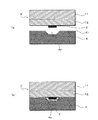
図3は、窪み形状を有する基板に対するインクパターンの転写の状態を説明する模式断面図である。図3(a)に示すように、インク3のパターンが転写されたブランケット1’と基板4とを向かい合わせた位置合わせする。この例では、基板4の窪み4a内にパターンを形成することから、ブランケット1’のインク2のパターンと基板4の窪み4aとの位置を合わせて配置する。
[Problems of comparative example]
FIG. 3 is a schematic cross-sectional view for explaining the state of transfer of the ink pattern to the substrate having a depression shape. As shown in FIG. 3A, the
そして、図3(b)に示すように、ブランケット1’と基板4とを加圧接触させる。この際、ブランケット1’のPDMS層12が弾性変形する。しかし、その変形量が基板4の窪み4aの深さより少ない場合、インクパターンは基板4の窪み4aの底部まで到達せず、インク2のパターンは転写されないことになる。
Then, as shown in FIG. 3B, the
このような転写不良を解消するため、ブランケット1’の加圧接触時のPDMS層12の弾性変形量を増加させるには、その厚みを厚くすれば良い。しかし、図4(a)に示すように、ブランケット1’のPDMS層12の厚さを増加させると、第1転写工程においてブランケット1’と版3とを加圧接触させる際、PDMS層12の弾性変形が版3の凹部3aの底まで到達してしまうことになる。これにより、図4(b)に示すように、版3の凹部3aの底に接したインク2が版3側に残り、ブランケット1’側に残すはずのパターンに抜けの不良が発生する。
In order to eliminate such a transfer defect, in order to increase the amount of elastic deformation of the
パターン不良が発生しないPDMS層12の厚みは、1〜10μmであることが実験的に分かっている。しかし、1〜10μm厚みでは1μm以上の凹部深さを有する基板へは転写不良が発生することになる。
It has been experimentally found that the thickness of the
<2.本実施形態に係る転写パターン形成方法>
[ブランケットの構造]
図5は、本実施形態に係る転写パターン形成方法で適用されるブランケットの構造を説明する模式断面図である。図5(a)に示すように、本実施形態に係るブランケット1は、凹部11aが形成された硬質の基材11と、硬質の基材11より軟らかい材質であるPDMS層12とから構成される。硬質の基材11は軟質の基材であるPDMS層12と貼り合わされている。これにより、PDMS層12は、基材11の凹部11aの位置の厚さが他より厚く設けられることになる。
<2. Transfer Pattern Forming Method According to this Embodiment>
[Blanket structure]
FIG. 5 is a schematic cross-sectional view illustrating the structure of a blanket applied in the transfer pattern forming method according to this embodiment. As shown in FIG. 5A, the
このブランケット1では、硬質の基材11としてガラス基板や金属基板を用い、エッチングによって凹部11aを形成している。本実施形態では、ガラス基板を用いている。硬質の基材11の厚みは、例えば10μm〜500μm程度とする。
In this
軟質の基材として利用されるPDMS層12は、硬質の基材11の凹部11aに埋め込まれるとともに、凹部11aが形成された面の全面に貼り付けられている。PDMS層12の厚みは、例えば1μm〜10μm程度である。なお、本実施形態では軟質の基材としてPDMS層12を用いるが、これは一例である。
The
ブランケット1を製造するには、先ず、図5(b)に示すように、例えばガラス基板から成る硬質の基材11の所定位置に凹部11aを形成する。凹部11aは、フォトリソグラフィ技術によって基材11の凹部形成位置のみをエッチングすることで形成される。具体的には、硬質の基材11の、版の凹部パターンと対応する位置をエッチングして凹部11aを形成する。深さは、パターン形成対象の基板の窪みの深さにもよるが、5μm〜200μm程度とする。
In order to manufacture the
なお、パターンを転写する基板との位置合わせ用のマークも凹部パターンとして同時に形成してもよい。すなわち、凹部を形成する際のエッチングによって同時に位置合わせ用のマークも形成する。通常は、第1転写工程でブランケット1にインクのパターンを転写するのと同時にインクによるマークも形成するが、インクの厚さが例えば10nm以下といった極薄く形成される場合にはマークとして視認性が悪くなる。そこで、基材11の凹部11aをエッチングによって形成する工程と同時にマークもエッチングによって形成しておく。これにより、インクをマークとして利用できない場合でもエッチングによるマークを利用できるようになる。
The mark for alignment with the substrate to which the pattern is transferred may be formed simultaneously as a concave pattern. That is, an alignment mark is also formed by etching at the time of forming the recess. Normally, an ink mark is also formed at the same time as the ink pattern is transferred to the
次に、図5(c)に示すように、硬質の基材11の凹部11aを形成した面にPDMS層12を1〜10μm厚程度で塗布する。PDMSは自己平滑化作用が強く、表面が平坦な凹部パターン付きのブランケット1が構成される。これにより、凹部11aの位置では他の位置に比べてPDMS層12が厚く形成されたブランケット1が形成されることになる。
Next, as shown in FIG.5 (c), the
ここで、ブランケット1の凹部11a以外の位置におけるPDMS層12の厚さをa、凹部11aの位置のPDMS層12の厚さをbとした場合、b/a≧1.5が成り立つようにする。PDMS層12の厚さが部分的に厚くなると、厚さの比率に応じて第1転写工程および第2転写工程での加圧による弾性変形量を部分的に調整できるようになる。つまり、PDMS層12の厚さが厚いほど同じ加圧力での弾性変形量を大きくすることができる。
Here, when the thickness of the
また、ブランケット1の凹部11aの幅は、後述する転写パターン形成方法における第1転写工程で用いる版の凹部の幅より狭くなっている。これにより、第1転写工程において版との加圧接触を行う際、版の凹部との関係ではPDMS層12の弾性変形量を小さくでき、PDMS層12が版の凹部の底に接触してしまうことを回避して転写不良を解消できることになる。
Further, the width of the
また、ブランケット1の凹部11aの幅は、後述するインクのパターンを転写する対象である基板に設けられる窪みの幅より広くなっている。これにより、第2転写工程において基板との加圧接触を行う際、基板の窪みとの関係ではPDMS層12の弾性変形量を大きくでき、PDMS層12が基板の窪みの底に接触してインクのパターンを確実に窪み内へ転写できるようになる。
Further, the width of the
このような特性を利用して、本実施形態では第1転写工程および第2転写工程でのパターン転写不良を解消する。 Utilizing such characteristics, in this embodiment, pattern transfer defects in the first transfer process and the second transfer process are eliminated.
[本実施形態のブランケットを用いた転写パターンの形成手順]
図6〜図7は、本実施形態のブランケットを用いた転写パターンの形成手順を説明する模式断面図である。先ず、図6(a)に示すように、先に説明した本実施形態のブランケット1を用意する。そして、ブランケット1のPDMS層12の表面にインク2を一様に塗布する。インク2としては、例えば、銀、ニッケル、金、銅、その他金属を含有する材料を用いる。
[Procedure for Forming Transfer Pattern Using Blanket of this Embodiment]
6 to 7 are schematic cross-sectional views for explaining a transfer pattern forming procedure using the blanket of the present embodiment. First, as shown in FIG. 6A, the
その後、ブランケット1のインク2を塗布した面と版3とを向かい合わせで配置する。この際、ブランケット1の凹部11aと版3の凹部3aとの位置が合うよう位置決めする。
Thereafter, the surface of the
次に、図6(b)に示すように、ブランケット1と版3とを加圧接触させる。すなわち、ブランケット1のインク面を版3の表面に加圧圧縮によって接触させる。加圧圧縮による接触は、圧縮気体加圧法を用いる。圧縮気体加圧法とは、接触させる対象であるブランケット1と版3とをそれぞれ向かい合わせて近接しつつ、所定のステージ上に固定する。そして、この状態でブランケット1および版3のうち一方の背面側から圧縮気体を噴射させて押し出すこれにより、ブランケット1と版3とを接触させる方法である。
Next, as shown in FIG. 6B, the
これによって、版3の凹部3aの周辺(凸部)にブランケット1のインク2が付着する状態となる。この際、版3の凹部3aの位置では、ブランケット1のPDMS層12が凹部3a内に押し込まれ湾曲する状態となる。しかし、ブランケット1の凹部11aの幅を、版3の凹部3aの幅より狭くしておくと、版3の凹部3aの縁ではPDMS層12の薄い部分(図中矢印d参照)と当接することになる。
As a result, the
版3の凹部3a内に押し込まれるPDMS層12の量は版3の凹部3aの縁でのPDMS層12の厚さ起因するため、同じ加圧力であれば版3の凹部3aの縁でのPDMS層12の厚さが薄いほど版3の凹部3a内へ押し込まれるPDMS層12の量を少なくできる。したがって、本実施形態では、ブランケット1にPDMS層12の厚い部分があっても、版3の凹部3a内に押し込まれるPDMS層12が版3の凹部3aの底部まで達するまでには至らない。
Since the amount of the
次に、図6(c)に示すように、ブランケット1と版3とを分離すると、版3の凸部にインク2が付着し、ブランケット1側には版3の凹部3aに対応したインク2のパターンが残る状態となる。この図6(a)〜(c)に示す工程が、ブランケット1側へのインク2のパターンの転写工程、すなわち、第1転写工程となる。
Next, as shown in FIG. 6C, when the
次に、図7(a)に示すように、インク2のパターンが残されたブランケット1と密着層41が形成された基板4とを向かい合わせ、位置合わせした状態で加圧接触させる。ブランケット1を基板4に位置合わせする際、本実施形態では、ブランケット1の凹部11aとともに形成したマーク(図示せず)を利用する。すなわち、ブランケット1に形成したマークと基板4に予め設けられたマークとを合わせることで、正確な位置合わせが成される。
Next, as shown in FIG. 7A, the
また、本実施形態では、基板4には窪み4aが設けられており、この窪み4a内にインク2のパターンを形成することになる。この基板4の窪み4aは例えば上下の配線を接続するためのコンタクトホールである。そして、図7(b)に示すように、ブランケット1と基板4とを加圧接触させると、基板4の窪み4a位置に対応するブランケット1のPDMS層12が基板4の窪み4a内に押し込まれる。これにより、インク2のパターンが窪み4aの底部まで到達してインク2のパターンが転写されることになる。
In the present embodiment, the
ここで、ブランケット1の凹部11aの幅を基板4の窪み4aの幅より広くしておくと、基板4の窪み4aの縁ではPDMS層12の厚い部分(図中矢印D参照)と当接することになる。
Here, if the width of the
基板4の窪み4a内に押し込まれるPDMS層12の量は、基板4の窪み4aの縁でのPDMS層12の厚さ起因する。したがって、同じ加圧力であれば基板4の窪み4aの縁でのPDMS層12の厚さが厚いほど基板4の窪み4a内へ押し込まれるPDMS層12の量が多くなる。
The amount of the
本実施形態では、ブランケット1のPDMS層12の厚い部分によってPDMS層12が基板4の窪み4a内に十分押し込まれ、PDMS層12に残っているインク2のパターンを基板4の窪み4aの底部に達するまで接触させている。これにより、パターンの転写を行うことが可能となる。
In the present embodiment, the
その後、図7(c)に示すように、ブランケット1と基板4とを分離する。これにより、ブランケット1に残されていたインク2のパターンが基板4上に転写されることになる。図7(a)〜(c)に示す工程が、ブランケット1から基板4へのパターンの転写工程、すなわち、第2転写工程となる。
Thereafter, as shown in FIG. 7C, the
この第2転写工程では、窪み4aが設けられた基板4にインク2のパターンを転写する場合でも、窪み4a内に確実にブランケット1のPDMS層12を押し込むことができる。これにより、パターンを基板4の窪み4aに確実に接触させて、パターン転写の不良を回避できることになる。
In the second transfer step, even when the pattern of the
<3.パターン転写装置>
[装置構成:主として第1転写工程での適用例]
図8は、パターン転写装置の例を示す模式断面図である。このパターン転写装置は、先に説明した圧縮気体加圧法による加圧圧縮を行う装置である。パターン転写装置によるパターンの転写は、第1転写工程および第2転写工程のいずれでも用いることができる。
<3. Pattern transfer device>
[Apparatus configuration: application example mainly in the first transfer step]
FIG. 8 is a schematic cross-sectional view showing an example of a pattern transfer apparatus. This pattern transfer device is a device that performs pressure compression by the compressed gas pressure method described above. Pattern transfer by the pattern transfer apparatus can be used in either the first transfer process or the second transfer process.
ブランケットに版のパターンを転写する第1転写工程で用いるパターン転写装置では、例えば図8(a)に示したように、ブランケットの外周部を、下部ステージ51、Oリング53A,53Bおよび固定フレーム54A,54Bにより機械的に固定する。また、版3を上部ステージ52により固定し、下部ステージ51の中心付近に設けられた開口部510(真空排気口および圧縮気体導入口として機能する)から圧縮気体を噴射させてブランケット1を押し出すようにする。
In the pattern transfer apparatus used in the first transfer process for transferring the pattern of the plate to the blanket, for example, as shown in FIG. 8A, the outer periphery of the blanket is placed on the
なお、例えば図8(b)に示したように、ブランケット1の外周部を、下部ステージ51Aに設けられた開口部511A,511Bにより、図中の符号P2,P3で示したように真空吸着させて固定するようにしてもよい。
For example, as shown in FIG. 8B, the outer periphery of the
また、例えば図9に示したように、版3が下部ステージ51上に固定されるものでもよい。この転写装置は、版3を下部ステージ51上に固定するとともに、ブランケット1の外周部を固定フレーム54C,54Dにより固定する。さらに膨張可能であり柔軟性を有する伸縮性フィルム55を、Oリング53A,53B、固定フレーム54A,54Bおよび上部ステージ52Aにより固定する。そして、上部ステージ52Aの中心付近に設けられた開口部520(真空排気口および圧縮気体導入口として機能する)から圧縮気体を噴射させて伸縮性フィルム55およびブランケット1を押し出すようにしている。この場合、ブランケット1の外周部を機械的に固定するだけでよい。
For example, as shown in FIG. 9, the
なお、これらの場合において、ブランケット1と版3とを近接させる距離は1μm〜1mmの距離とし、転写圧力は0.1kPa〜100kPa程度として精密に制御する。これにより、ブランケット1上で、均一かつ低圧力で制御できるため、押しつぶれのないインクの転写が可能となる。なお、これら図4および図5においては、インクの図示は省略している。
In these cases, the
[第2転写工程での適用例]
また、パターン転写装置によってブランケット1から基板4へのインクのパターンの転写、すなわち第2転写工程を行う場合には、上記第1転写工程で用いるパターン転写装置において、版3を基板4に置き換えるようにすればよい。
[Example of application in the second transfer step]
When the pattern transfer device performs the transfer of the ink pattern from the
1…ブランケット、11a…凹部、2…インク、3…版、3a…凹部、4…基板、4a…窪み、11…基材、12…PDMS層
DESCRIPTION OF
Claims (9)
形成するパターンの位置に凹部が設けられた版を用い、当該版の凹部と前記ブランケットの凹部との位置を合わせるようにして当該版と前記ブランケットとを互いに向かい合わせ、これらを加圧接触させることにより、前記ブランケットのインクのうち前記版の凹部に対応する部分のみを前記ブランケット側に残して転写させる第1転写工程と、
前記第1転写工程後のブランケットと、パターンを形成する基板とを互いに向かい合わせるとともに、これらを加圧接触させることにより、前記ブランケット上に残っているインクを前記基板上に転写させる第2転写工程と
を有する転写パターン形成方法。 Using a blanket in which a hard base material in which a concave portion is formed and a soft base material softer than the hard base material are bonded together, and the thickness of the soft base material at the position of the concave portion is thicker than others, the soft base material An application process for applying ink to the surface of
Using a plate in which a recess is provided at the position of the pattern to be formed, aligning the position of the recess of the plate and the recess of the blanket so that the plate and the blanket face each other and press-contact them A first transfer step of transferring only the portion of the blanket ink corresponding to the concave portion of the plate on the blanket side; and
The second transfer step of transferring the ink remaining on the blanket onto the substrate by bringing the blanket after the first transfer step and the substrate on which the pattern is formed face each other and bringing them into pressure contact with each other A transfer pattern forming method comprising:
請求項1記載の転写パターン形成方法。 The transfer pattern forming method according to claim 1, wherein a width of the concave portion of the blanket is narrower than a width of the concave portion of the plate.
請求項1または2記載の転写パターン形成方法。 The transfer pattern forming method according to claim 1, wherein a recess is provided at a position of the substrate where the ink is transferred, and a width of the recess of the blanket is wider than a width of the recess of the substrate.
請求項1から3のうちいずれか1項に記載の転写パターン形成方法。 The transfer pattern forming method according to any one of claims 1 to 3, wherein the soft base material of the blanket is PDMS (polydimethylsiloxane).
前記硬質基材より軟らかい材質から成り、前記硬質基材と貼り合わされ、前記硬質基材の凹部の位置の厚さが他より厚く設けられた軟質基材と
を有する転写パターン形成用ブランケット。 A hard base material with a recess,
A blanket for forming a transfer pattern, comprising: a soft base material made of a material softer than the hard base material, and a soft base material bonded to the hard base material and provided with a thicker concave portion than the others.
請求項5記載の転写パターン形成用ブランケット。 The blanket for forming a transfer pattern according to claim 5, wherein the width of the concave portion of the hard substrate is narrower than the width of the concave portion of the plate to be left corresponding to the pattern for forming the ink applied to the surface of the soft substrate.
請求項5または6記載の転写パターン形成用ブランケット。 The blanket for forming a transfer pattern according to claim 5 or 6, wherein a width of the concave portion of the hard base material is wider than a width of a recess provided in a substrate to which the ink pattern is transferred.
b/a≧1.5が成り立つ
請求項5から7のうちいずれか1項に記載の転写パターン形成用ブランケット。 When the thickness of the soft base material at a position other than the concave portion of the hard base material is a, and the thickness of the soft base material at the concave portion of the hard base material is b,
The blanket for forming a transfer pattern according to claim 5, wherein b / a ≧ 1.5 holds.
請求項5から8のうちいずれか1項に記載の転写パターン形成用ブランケット。 The transfer pattern forming blanket according to any one of claims 5 to 8, wherein the soft base material is PDMS (polydimethylsiloxane).
Priority Applications (1)
| Application Number | Priority Date | Filing Date | Title |
|---|---|---|---|
| JP2008227759A JP5380958B2 (en) | 2008-09-05 | 2008-09-05 | Transfer pattern forming method |
Applications Claiming Priority (1)
| Application Number | Priority Date | Filing Date | Title |
|---|---|---|---|
| JP2008227759A JP5380958B2 (en) | 2008-09-05 | 2008-09-05 | Transfer pattern forming method |
Publications (2)
| Publication Number | Publication Date |
|---|---|
| JP2010058415A true JP2010058415A (en) | 2010-03-18 |
| JP5380958B2 JP5380958B2 (en) | 2014-01-08 |
Family
ID=42185773
Family Applications (1)
| Application Number | Title | Priority Date | Filing Date |
|---|---|---|---|
| JP2008227759A Expired - Fee Related JP5380958B2 (en) | 2008-09-05 | 2008-09-05 | Transfer pattern forming method |
Country Status (1)
| Country | Link |
|---|---|
| JP (1) | JP5380958B2 (en) |
Cited By (4)
| Publication number | Priority date | Publication date | Assignee | Title |
|---|---|---|---|---|
| JP2012081622A (en) * | 2010-10-08 | 2012-04-26 | Fujikura Rubber Ltd | Blanket, and printing apparatus |
| JP2013111910A (en) * | 2011-11-30 | 2013-06-10 | Dainippon Screen Mfg Co Ltd | Pattern transfer apparatus, and pattern transfer method |
| JP2014144628A (en) * | 2013-01-30 | 2014-08-14 | Dainippon Screen Mfg Co Ltd | Pattern forming device |
| JP2014166746A (en) * | 2013-01-30 | 2014-09-11 | Dainippon Screen Mfg Co Ltd | Pattern formation device and pattern formation method |
Citations (3)
| Publication number | Priority date | Publication date | Assignee | Title |
|---|---|---|---|---|
| JPH05155172A (en) * | 1991-12-10 | 1993-06-22 | Matsushita Electric Ind Co Ltd | Blanket |
| JP2006137188A (en) * | 2004-11-13 | 2006-06-01 | Man Roland Druckmas Ag | Sleeve, in particular, rubber blanket sleeve |
| JP2007160769A (en) * | 2005-12-15 | 2007-06-28 | Toppan Printing Co Ltd | Removing plate for reverse offset printing and method for forming conductive pattern lising the same |
-
2008
- 2008-09-05 JP JP2008227759A patent/JP5380958B2/en not_active Expired - Fee Related
Patent Citations (3)
| Publication number | Priority date | Publication date | Assignee | Title |
|---|---|---|---|---|
| JPH05155172A (en) * | 1991-12-10 | 1993-06-22 | Matsushita Electric Ind Co Ltd | Blanket |
| JP2006137188A (en) * | 2004-11-13 | 2006-06-01 | Man Roland Druckmas Ag | Sleeve, in particular, rubber blanket sleeve |
| JP2007160769A (en) * | 2005-12-15 | 2007-06-28 | Toppan Printing Co Ltd | Removing plate for reverse offset printing and method for forming conductive pattern lising the same |
Cited By (4)
| Publication number | Priority date | Publication date | Assignee | Title |
|---|---|---|---|---|
| JP2012081622A (en) * | 2010-10-08 | 2012-04-26 | Fujikura Rubber Ltd | Blanket, and printing apparatus |
| JP2013111910A (en) * | 2011-11-30 | 2013-06-10 | Dainippon Screen Mfg Co Ltd | Pattern transfer apparatus, and pattern transfer method |
| JP2014144628A (en) * | 2013-01-30 | 2014-08-14 | Dainippon Screen Mfg Co Ltd | Pattern forming device |
| JP2014166746A (en) * | 2013-01-30 | 2014-09-11 | Dainippon Screen Mfg Co Ltd | Pattern formation device and pattern formation method |
Also Published As
| Publication number | Publication date |
|---|---|
| JP5380958B2 (en) | 2014-01-08 |
Similar Documents
| Publication | Publication Date | Title |
|---|---|---|
| KR101733585B1 (en) | Method for fabricating ink pattern and printing apparatus of ink pattern | |
| KR101545004B1 (en) | Method and system for contacting of a flexible sheet and a substrate | |
| JP5380958B2 (en) | Transfer pattern forming method | |
| CN111224019B (en) | Mask support template, method for manufacturing the same, and method for manufacturing mask and frame connector | |
| WO2014092015A1 (en) | Electronic device manufacturing method, and glass laminate manufacturing method | |
| JP5258973B2 (en) | Stripping in imprint lithography process | |
| TW200950973A (en) | Intaglio printing plate, production method for intaglio printing plate, production method for electronic substrate, and production method for display device | |
| JP5195074B2 (en) | Mold | |
| KR20160024410A (en) | Pattern structure and method of manufacturing the same | |
| JP2010143103A (en) | Transfer pattern forming blanket, transfer pattern forming method, and transfer apparatus | |
| WO2021155736A1 (en) | Pattern transfer device and method | |
| JP4998397B2 (en) | Imprint method, information recording medium manufacturing method, and imprint system | |
| JP2004138973A (en) | Flexographic printing plate, flexographic printing system, method for manufacturing flexographic printing plate, and method for manufacturing printed matter | |
| JP4182689B2 (en) | Letterpress and pattern forming method | |
| JP2010089442A (en) | Transfer pattern forming method, transfer pattern forming plate, method of manufacturing transfer pattern forming plate, and transfer device | |
| JP2014104712A (en) | Electronic device manufacturing method and multilayered glass laminate | |
| JP5319910B2 (en) | Method of embedding conductive pattern, method of manufacturing laminated substrate, and method of manufacturing fine channel structure | |
| KR20200137591A (en) | Mask metal sheet for producing mask | |
| JP2013043445A (en) | Mold, imprint device, imprint method, and article production method | |
| JP2010010247A (en) | Substrate carrying tool and method of manufacturing element substrate | |
| JP2004235386A (en) | Positioning table and positioning method | |
| WO2016024446A1 (en) | Flexographic printing plate manufacturing method and liquid crystal display element manufacturing method | |
| CN113490883A (en) | Large area seamless master and imprint stamp manufacturing method | |
| KR101551772B1 (en) | Replica stamp for SCIL process and manufacturing method for thereof | |
| JP2016144878A (en) | Device and method for forming pattern film into three-dimensional convex shape |
Legal Events
| Date | Code | Title | Description |
|---|---|---|---|
| A521 | Written amendment |
Free format text: JAPANESE INTERMEDIATE CODE: A821 Effective date: 20100909 |
|
| RD02 | Notification of acceptance of power of attorney |
Free format text: JAPANESE INTERMEDIATE CODE: A7422 Effective date: 20100909 |
|
| A621 | Written request for application examination |
Free format text: JAPANESE INTERMEDIATE CODE: A621 Effective date: 20110629 |
|
| A977 | Report on retrieval |
Free format text: JAPANESE INTERMEDIATE CODE: A971007 Effective date: 20130405 |
|
| A131 | Notification of reasons for refusal |
Free format text: JAPANESE INTERMEDIATE CODE: A131 Effective date: 20130409 |
|
| A521 | Written amendment |
Free format text: JAPANESE INTERMEDIATE CODE: A523 Effective date: 20130527 |
|
| TRDD | Decision of grant or rejection written | ||
| A01 | Written decision to grant a patent or to grant a registration (utility model) |
Free format text: JAPANESE INTERMEDIATE CODE: A01 Effective date: 20130903 |
|
| A61 | First payment of annual fees (during grant procedure) |
Free format text: JAPANESE INTERMEDIATE CODE: A61 Effective date: 20130916 |
|
| LAPS | Cancellation because of no payment of annual fees |