JP2010058276A - Inkjet printer - Google Patents

Inkjet printer Download PDF

Info

Publication number
JP2010058276A
JP2010058276A JP2008223305A JP2008223305A JP2010058276A JP 2010058276 A JP2010058276 A JP 2010058276A JP 2008223305 A JP2008223305 A JP 2008223305A JP 2008223305 A JP2008223305 A JP 2008223305A JP 2010058276 A JP2010058276 A JP 2010058276A
Authority
JP
Japan
Prior art keywords
projector
carriage
light
light receiver
nozzle
Prior art date
Legal status (The legal status is an assumption and is not a legal conclusion. Google has not performed a legal analysis and makes no representation as to the accuracy of the status listed.)
Granted
Application number
JP2008223305A
Other languages
Japanese (ja)
Other versions
JP5245654B2 (en
Inventor
Takao Hosaka
隆男 保坂
Hiroaki Arakawa
裕明 荒川
Current Assignee (The listed assignees may be inaccurate. Google has not performed a legal analysis and makes no representation or warranty as to the accuracy of the list.)
Konica Minolta IJ Technologies Inc
Original Assignee
Konica Minolta IJ Technologies Inc
Priority date (The priority date is an assumption and is not a legal conclusion. Google has not performed a legal analysis and makes no representation as to the accuracy of the date listed.)
Filing date
Publication date
Application filed by Konica Minolta IJ Technologies Inc filed Critical Konica Minolta IJ Technologies Inc
Priority to JP2008223305A priority Critical patent/JP5245654B2/en
Publication of JP2010058276A publication Critical patent/JP2010058276A/en
Application granted granted Critical
Publication of JP5245654B2 publication Critical patent/JP5245654B2/en
Expired - Fee Related legal-status Critical Current
Anticipated expiration legal-status Critical

Links

Images

Landscapes

  • Ink Jet (AREA)
  • Accessory Devices And Overall Control Thereof (AREA)

Abstract

<P>PROBLEM TO BE SOLVED: To provide an inkjet printer free from possibility of collision of a projector with a photoreceiver, not requiring a communication distance to be elongated uselessly, not restricting positions of various devices arranged outside a recording area, and allowing optical communication between a carriage side and a printer body side. <P>SOLUTION: In the inkjet printer, the carriage 1 mounted with a recording head 3 is arranged movable along a main scanning direction in a printer body, the communication between the carriage 1 side and the printer body side is performed by arranging either of the projector 8 and the photoreceiver 9 in the carriage 1 side, and the other in the printer body side. The one arranged in the printer body side out of the projector 8 and the photoreceiver 9 is arranged in a position lower than that of the other arranged in the carriage 1 side, and the projector 8 and the photoreceiver 9 are attached so as to make each of their optical paths L1, L2 oblique to the main scanning direction. <P>COPYRIGHT: (C)2010,JPO&INPIT

Description

本発明はインクジェットプリンタに関し、詳しくは、ノズルからインクを吐出する記録ヘッドを、プリンタ本体に主走査方向に移動可能に設けられたキャリッジ上に搭載し、キャリッジ側とプリンタ本体側との間の通信を、投光機と受光機を用いた光通信によって行うようにしたインクジェットプリンタに関する。   The present invention relates to an ink jet printer, and more specifically, a recording head for ejecting ink from nozzles is mounted on a carriage provided on a printer main body so as to be movable in a main scanning direction, and communication between the carriage side and the printer main body side is performed. The present invention relates to an ink jet printer that performs optical communication using a projector and a light receiver.

ノズルからインクを吐出する記録ヘッドをキャリッジに搭載し、該キャリッジをプリンタ本体に主走査方向に移動可能に設けたインクジェットプリンタにおいて、キャリッジ側とプリンタ本体側との間の通信を、投光機と受光機を用いた光通信によって行うようにしたものが知られている(特許文献1、2)。   In an ink jet printer in which a recording head for ejecting ink from nozzles is mounted on a carriage and the carriage is provided on the printer main body so as to be movable in the main scanning direction, communication between the carriage side and the printer main body side is performed with a projector. What is known to be performed by optical communication using a light receiver is known (Patent Documents 1 and 2).

これによると、キャリッジ側とプリンタ本体側との間を従来のリボンケーブル等の信号線を用いて接続する場合に生じる問題を解決することができる。
特開平6−143725号公報 特開平7−108737号公報
According to this, it is possible to solve the problem that occurs when the carriage side and the printer body side are connected using a signal line such as a conventional ribbon cable.
JP-A-6-143725 Japanese Patent Laid-Open No. 7-108737

しかし、この場合、次のような新たな課題がある。   However, in this case, there are the following new problems.

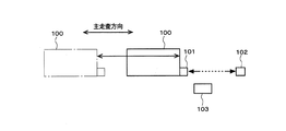
すなわち、投光機と受光機とのうちの一方をキャリッジ側に、他方をプリンタ本体側に配置した場合、両者の光軸を合わせるため、投光機と受光機を光軸が主走査方向に沿って同一軸となるように対向させて配置するようにしている。図16はキャリッジ100に受光機101を設け、プリンタ本体に投光機102を設けた態様を示している。   That is, when one of the projector and the light receiver is disposed on the carriage side and the other is disposed on the printer body side, the light axis of the light projector and the light receiver are aligned in the main scanning direction in order to match the optical axes of both. It is made to arrange so that it may become the same axis along. FIG. 16 shows a mode in which a light receiver 101 is provided on the carriage 100 and a projector 102 is provided on the printer body.

このとき、キャリッジ100が主走査方向に沿ってオーバーランした場合、投光機102と受光機101とが衝突して破壊されてしまうおそれがある。このため、キャリッジ100のオーバーランを検出するためのセンサ103を設け、このセンサ103によってオーバーランが検出された場合にキャリッジ100を強制的に停止させるための手段を講じる必要があり、部品数増によって構造が複雑化すると共にコスト増を招く問題がある。   At this time, if the carriage 100 overruns in the main scanning direction, the projector 102 and the light receiver 101 may collide and be destroyed. Therefore, it is necessary to provide a sensor 103 for detecting an overrun of the carriage 100, and to take a means for forcibly stopping the carriage 100 when the overrun is detected by the sensor 103. As a result, the structure becomes complicated and the cost increases.

また、投光機又は受光機をプリンタ本体側に配置する場合、取り付ける位置がプリンタ本体のカバー等の比較的たわみ易い外装部材であるような場合、位置ズレが大きくなり、精度のよい通信ができなくなるおそれがあり、そのために、金属ステー等の安定した取付け部材を追加すると、やはり部品数増によるコスト増の問題や追加部材の取付けスペースの確保の問題がある。   In addition, when the projector or receiver is arranged on the printer body side, if the mounting position is a relatively flexible exterior member such as a cover of the printer body, the positional deviation increases and accurate communication is possible. For this reason, if a stable mounting member such as a metal stay is added, there is still a problem of cost increase due to an increase in the number of parts and a problem of securing a mounting space for the additional member.

更に、キャリッジ100の主走査方向の移動範囲は、図16のように投光機102と受光機101とが対向しているため、最大で投光機102の取付け位置までの範囲に限定されることになる。プリンタ本体には、図17に示すように、記録ヘッドによる記録領域外に、記録ヘッドの各ノズルからのインク吐出の有無を検出するためのノズル欠検知装置104や、記録ヘッドのノズル面をワイピングしたり、ノズルからインクを吸引したりするメンテナンス装置105等を配置する場合があるが、これらの装置は、プリンタ本体側の投光機102の取付け位置よりも遠い側に配置することができず、いずれも投光機102よりも内側に配置せざるを得なくなる。   Further, the moving range of the carriage 100 in the main scanning direction is limited to the range up to the mounting position of the projector 102 because the projector 102 and the light receiver 101 face each other as shown in FIG. It will be. As shown in FIG. 17, the printer main body is wiped with a nozzle missing detection device 104 for detecting the presence or absence of ink ejection from each nozzle of the recording head and the nozzle surface of the recording head outside the recording area of the recording head. However, these devices cannot be arranged on the side farther than the mounting position of the projector 102 on the printer main body side. In either case, the projector 102 must be disposed inside the projector 102.

この場合、プリンタ本体側の投光機102の取付け位置を、図17のようにノズル欠検知装置104やメンテナンス装置105よりも外側にすると、キャリッジ100側の受光機101とプリンタ本体側の投光機102との間の通信距離が無駄に長くなってしまう。ノズル欠検知装置104によって欠検知を行う場合は、キャリッジ100側とプリンタ本体側との間で検出信号等の各種信号を頻繁に送受信する必要があるが、メンテナンス装置105によってメンテナンスを行う場合は、プリンタ本体側の制御だけで稼働するため、キャリッジ100側とプリンタ本体側との間で通信を行う必要がないためである。通信距離が長くなると、受光感度を上げるために増幅率を上げること等によってノイズの影響を受け易くなり、精度良く通信を行うことが困難になる問題がある。   In this case, if the mounting position of the projector 102 on the printer main body side is outside the nozzle missing detection device 104 and the maintenance device 105 as shown in FIG. 17, the light receiver 101 on the carriage 100 side and the light projection on the printer main body side. The communication distance with the device 102 becomes unnecessarily long. When missing detection is performed by the nozzle missing detection device 104, it is necessary to frequently transmit and receive various signals such as detection signals between the carriage 100 side and the printer body side, but when maintenance is performed by the maintenance device 105, This is because the operation is performed only by the control on the printer body side, and it is not necessary to perform communication between the carriage 100 side and the printer body side. When the communication distance becomes long, there is a problem that it becomes difficult to perform communication with high accuracy because it becomes susceptible to noise by increasing the amplification factor to increase the light receiving sensitivity.

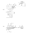
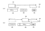
このため、図18(a)のように、メンテナンス装置105をプラテン106側に配置したり、図18(b)のように、メンテナンス装置105を、プラテン106を間に挟んでノズル欠検知装置104と反対側に配置したりすれば、投光機102の位置を、ノズル欠検知装置104に位置したキャリッジ100側の受光機101に近接させて配置することができ、通信距離が短くなって精度良く通信を行うことができるようになるが、次のような問題がある。   Therefore, as shown in FIG. 18A, the maintenance device 105 is arranged on the platen 106 side, or as shown in FIG. 18B, the maintenance device 105 is placed between the platen 106 and the nozzle missing detection device 104. The projector 102 can be placed close to the light receiver 101 on the carriage 100 side located in the nozzle missing detection device 104, and the communication distance is shortened and the accuracy is improved. Although communication can be performed well, there are the following problems.

一般に、ノズル欠検知は所定のタイミングでキャリッジ100がノズル欠検知装置104の位置まで移動して来ることによって実行され、ノズル欠検知の結果、ノズルが正常であれば、直ぐにキャリッジ100を記録領域内まで戻して次の記録を再開することができるように、プラテン106に隣接して配置されることが望まれる。ここで、ノズル欠検知の結果、ノズル詰まり等の異常が発見された場合は、キャリッジ100をメンテナンス装置105の位置まで移動させてメンテナンスを行う必要がある。   In general, nozzle missing detection is performed by moving the carriage 100 to the position of the nozzle missing detection device 104 at a predetermined timing. If the nozzle is found normal as a result of nozzle missing detection, the carriage 100 is immediately moved into the recording area. It is desirable to place it adjacent to the platen 106 so that the next recording can be resumed. Here, if an abnormality such as nozzle clogging is detected as a result of the missing nozzle detection, it is necessary to perform maintenance by moving the carriage 100 to the position of the maintenance device 105.

ところが、図18(a)の場合では、ノズル欠検知を行う際、ノズル欠検知装置104の位置までメンテナンス装置105を越えてキャリッジ100を移動させなくてはならず、ノズル欠検知の結果、ノズルが正常でメンテナンスが不要の場合に記録を直ちに再開させたい場合も、ノズル欠検知装置104からメンテナンス装置105を越えてキャリッジ100を移動させなくてはならず、キャリッジ100の移動に無駄が多くなり、それだけ次の記録を再開するまでに時間が掛かってしまい、プリンタの記録速度を低下させる原因となってしまう。   However, in the case of FIG. 18A, when performing the missing nozzle detection, the carriage 100 must be moved over the maintenance device 105 to the position of the missing nozzle detection device 104. As a result of the missing nozzle detection, Even if normal and maintenance is unnecessary, it is necessary to move the carriage 100 beyond the maintenance device 105 from the nozzle missing detection device 104, and the movement of the carriage 100 becomes wasteful. Therefore, it takes time until the next recording is resumed, which causes a decrease in the recording speed of the printer.

また、図18(b)の場合では、キャリッジ100をノズル欠検知装置104まで移動させる際の無駄はなくなるが、ノズル欠検知の結果、ノズルが異常でメンテナンスが必要な場合、ノズル欠検知装置104からメンテナンス装置105までプラテン106を越えて長い距離を移動させなくてはならず、やはり、上記同様にプリンタの記録速度を低下させる原因となってしまう。   Further, in the case of FIG. 18B, there is no waste in moving the carriage 100 to the nozzle missing detection device 104. However, if the nozzle is abnormal and needs maintenance as a result of the nozzle missing detection, the nozzle missing detection device 104 is used. Therefore, it is necessary to move a long distance beyond the platen 106 from the maintenance device 105 to the maintenance device 105, which again causes a decrease in the recording speed of the printer.

そこで、本発明は、投光機と受光機とが衝突するおそれがなく、また、通信距離を無駄に長くする必要がなく、更に、記録領域外に配置される各種装置の位置に制約を与えることがなく、キャリッジ側とプリンタ本体側との間で光通信することのできるインクジェットプリンタを提供することを課題とする。   Therefore, the present invention does not cause the projector and the receiver to collide with each other, does not need to unnecessarily increase the communication distance, and further restricts the position of various devices arranged outside the recording area. It is an object of the present invention to provide an ink jet printer capable of optical communication between the carriage side and the printer main body side.

本発明の他の課題は、以下の記載により明らかとなる。   Other problems of the present invention will become apparent from the following description.

上記課題は以下の各発明によって解決される。   The above problems are solved by the following inventions.

請求項1記載の発明は、ノズルからインクを吐出する記録ヘッドを搭載したキャリッジをプリンタ本体に主走査方向に移動可能に設け、前記キャリッジ側と前記プリンタ本体側との間の通信を、投光機及び受光機のうちの一方を前記キャリッジ側に配置し、他方を前記プリンタ本体側に配置することによって光通信によって行うようにしたインクジェットプリンタであって、前記投光機及び前記受光機のうちの前記プリンタ本体側に配置した方を、前記キャリッジ及び該キャリッジと共に移動する部材の主走査方向に沿う移動経路上から外れた位置に取り付けられていると共に、前記投光機及び前記受光機の各々の光軸が主走査方向に対して斜めとなるように取り付けられていることを特徴とするインクジェットプリンタである。   According to the first aspect of the present invention, a carriage having a recording head for ejecting ink from the nozzles is provided in the printer main body so as to be movable in the main scanning direction, and communication between the carriage side and the printer main body side is performed by light projection One of the projector and the light receiver is disposed on the carriage side, and the other is disposed on the printer main body side so as to be performed by optical communication, wherein the projector and the light receiver Of the projector and the light receiving device are attached to the carriage and a position deviating from the movement path along the main scanning direction of the carriage and the member moving together with the carriage. The ink jet printer is attached so that the optical axis of the main body is inclined with respect to the main scanning direction.

請求項2記載の発明は、前記投光機及び前記受光機のうちの前記プリンタ本体側に配置した方が、前記キャリッジ側に配置した方よりも下位に配置されていることを特徴とする請求項1記載のインクジェットプリンタである。   The invention according to claim 2 is characterized in that the one of the projector and the light receiver arranged on the printer main body side is arranged lower than the one arranged on the carriage side. The inkjet printer according to Item 1.

請求項3記載の発明は、前記投光機及び前記受光機は、前記プリンタ本体を平面視した場合、互いの光軸が同一直線上となるように配置されていることを特徴とする請求項2記載のインクジェットプリンタである。   The invention according to claim 3 is characterized in that the light projector and the light receiver are arranged so that their optical axes are on the same straight line when the printer body is viewed in plan. 2. The inkjet printer according to 2.

請求項4記載の発明は、前記投光機及び前記受光機のうちの前記プリンタ本体側に配置した方が、前記キャリッジ側に配置した方よりも、副走査方向に沿うプリンタ本体の手前側又は奥側に配置されていることを特徴とする請求項1記載のインクジェットプリンタである。   According to a fourth aspect of the present invention, either the projector or the light receiver disposed on the printer body side is closer to the front side of the printer body along the sub-scanning direction than the one disposed on the carriage side. 2. The ink jet printer according to claim 1, wherein the ink jet printer is disposed on the back side.

請求項5記載の発明は、前記投光機及び前記受光機は、前記プリンタ本体を正面視した場合、互いの光軸が同一直線上となるように配置されていることを特徴とする請求項4記載のインクジェットプリンタである。   The invention according to claim 5 is characterized in that the projector and the light receiver are arranged so that their optical axes are on the same straight line when the printer body is viewed from the front. 4. The inkjet printer according to item 4.

請求項6記載の発明は、前記投光機は複数設けられ、それぞれ取付け角度を異ならせて配置されていることを特徴とする請求項1〜5のいずれかに記載のインクジェットプリンタである。   A sixth aspect of the present invention is the ink jet printer according to any one of the first to fifth aspects, wherein a plurality of the projectors are provided and arranged at different mounting angles.

請求項7記載の発明は、前記受光機は複数設けられ、それぞれ取付け角度を異ならせて配置されていることを特徴とする請求項1〜6のいずれかに記載のインクジェットプリンタである。   A seventh aspect of the present invention is the ink jet printer according to any one of the first to sixth aspects, wherein a plurality of the light receivers are provided and arranged at different mounting angles.

請求項8記載の発明は、前記投光機及び前記受光機の取付け角度は、互いの光軸の一致点が、通信動作時における前記キャリッジの主走査方向移動範囲両端の中間位置よりも遠い側寄りとなるように設定されていることを特徴とする請求項1〜5のいずれかに記載のインクジェットプリンタである。   According to an eighth aspect of the present invention, the mounting angle of the projector and the light receiver is such that the coincidence point between the optical axes is farther from an intermediate position between both ends of the moving range in the main scanning direction of the carriage during the communication operation. 6. The ink jet printer according to claim 1, wherein the ink jet printer is set so as to be close to each other.

請求項9記載の発明は、前記投光機及び前記受光機の通信距離に応じて、前記投光機の強度と前記受光機の感度のうちの少なくとも一方を変更する変更手段を有することを特徴とする請求項1〜8のいずれかに記載のインクジェットプリンタである。   The invention according to claim 9 includes a changing unit that changes at least one of the intensity of the light projector and the sensitivity of the light receiver according to a communication distance between the light projector and the light receiver. An ink jet printer according to any one of claims 1 to 8.

請求項10記載の発明は、前記投光機が前記プリンタ本体側、前記受光機が前記キャリッジ側に配置されることを特徴とする請求項1〜9のいずれかに記載のインクジェットプリンタである。   A tenth aspect of the present invention is the ink jet printer according to any one of the first to ninth aspects, wherein the projector is disposed on the printer body side and the light receiver is disposed on the carriage side.

請求項11記載の発明は、前記プリンタ本体に、前記記録ヘッドによる記録領域に隣接して、前記記録ヘッドの各ノズルから吐出されるインク滴を検出して検出信号を出力するノズル欠検知手段が配設されると共に、前記キャリッジ上に、前記記録ヘッドの各ノズルから前記ノズル欠検知手段によるノズル欠検知動作のための吐出開始信号を出力する吐出制御手段と、前記吐出制御手段からの吐出開始信号の出力から所定時間内の前記検知手段からの検出信号の有無によってノズル欠かどうかを判断する判断手段とを有するヘッド駆動基板を備えてなり、前記投光機は、前記ノズル欠検知手段による所定のノズル欠検知動作中の前記キャリッジの所定の移動範囲内において前記ノズル欠検知手段の検出信号を前記受光機に送信し、前記受光機は、受光された前記検出信号を前記ヘッド駆動基板の前記判断手段に送信する構成であることを特徴とする請求項10記載のインクジェットプリンタである。   According to an eleventh aspect of the invention, there is provided a nozzle missing detecting means for detecting a droplet of ink ejected from each nozzle of the recording head and outputting a detection signal adjacent to a recording area by the recording head in the printer body. A discharge control unit configured to output a discharge start signal for a nozzle missing detection operation by the nozzle missing detection unit from each nozzle of the recording head on the carriage; and a discharge start from the discharge control unit A head drive substrate having a determination unit that determines whether or not a nozzle is missing based on the presence or absence of a detection signal from the detection unit within a predetermined time from the output of the signal. A detection signal of the nozzle missing detection means is transmitted to the light receiver within a predetermined movement range of the carriage during the nozzle missing detection operation of the light receiver. , An ink jet printer according to claim 10, wherein it is configured to transmit the received by said detection signal to said determining means of the head drive substrate.

請求項12記載の発明は、前記ノズル欠検知手段を挟んで主走査方向の前記記録領域の反対側に、前記記録ヘッドのメンテナンスを行うためのメンテナンス手段が配置されており、前記投光機は、前記メンテナンス手段が配置されたメンテナンス領域内に配置されていることを特徴とする請求項11記載のインクジェットプリンタである。   According to a twelfth aspect of the present invention, maintenance means for performing maintenance of the recording head is disposed on the opposite side of the recording area in the main scanning direction across the nozzle missing detection means. The inkjet printer according to claim 11, wherein the inkjet printer is disposed in a maintenance area where the maintenance unit is disposed.

請求項13記載の発明は、前記投光機が前記キャリッジ側、前記受光機が前記プリンタ本体側に配置されることを特徴とする請求項1〜9のいずれかに記載のインクジェットプリンタである。   A thirteenth aspect of the present invention is the ink jet printer according to any one of the first to ninth aspects, wherein the projector is disposed on the carriage side and the light receiver is disposed on the printer main body side.

本発明によれば、投光機と受光機とが衝突するおそれがなく、また、通信距離を無駄に長くする必要がなく、更に、記録領域外に配置される各種装置の位置に制約を与えることがなく、キャリッジ側とプリンタ本体側との間で光通信することのできるインクジェットプリンタを提供することができる。   According to the present invention, there is no possibility that the projector and the receiver collide with each other, there is no need to unnecessarily increase the communication distance, and there are restrictions on the positions of various devices arranged outside the recording area. Therefore, it is possible to provide an ink jet printer capable of optical communication between the carriage side and the printer main body side.

以下、本発明の実施の形態について図面を用いて説明する。   Hereinafter, embodiments of the present invention will be described with reference to the drawings.

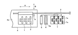
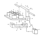
図1は本発明に係るインクジェットプリンタの要部を示す平面図、図2はその正面図である。   FIG. 1 is a plan view showing a main part of an ink jet printer according to the present invention, and FIG. 2 is a front view thereof.

図中、1はキャリッジであり、プリンタ本体の主走査方向(図中Aで示す方向)に亘って架設されたガイドレール2に沿って往復移動可能に設けられており、記録ヘッド3を搭載している。記録ヘッド3は、多数のノズルが配列されたノズル面3aを下面とし、ノズル列方向が主走査方向と直交する副走査方向(図中Bで示す方向)に沿うようにキャリッジ1に取付けられている。ここでは、9個の記録ヘッド3がキャリッジ1に千鳥状に配列されているが、本発明において記録ヘッド3の数は特に問わない。   In the figure, reference numeral 1 denotes a carriage, which is provided so as to be able to reciprocate along a guide rail 2 installed in the main scanning direction (direction A in the figure) of the printer body. ing. The recording head 3 is attached to the carriage 1 so that a nozzle surface 3a on which a large number of nozzles are arranged is a lower surface, and the nozzle row direction is along the sub-scanning direction (direction indicated by B in the figure) perpendicular to the main scanning direction. Yes. Here, nine recording heads 3 are arranged in a staggered manner on the carriage 1, but the number of recording heads 3 is not particularly limited in the present invention.

4はベルト搬送ユニットであり、詳細については省略するが、複数のローラに架け渡された搬送ベルトによって、紙、布帛、プラスチックシート等の記録メディアを副走査方向(図1中の下方向)に向けて搬送するようになっている。4aは搬送ベルト表面によって各記録ヘッド3のノズル面3aに対向するように形成されるプラテン面であり、このプラテン面4aに載置されて搬送される記録メディアに対して、キャリッジ1に搭載された各記録ヘッド3からインク滴が吐出され、所望の画像記録が行われるようになっている。   Reference numeral 4 denotes a belt conveyance unit. Although details are omitted, a recording medium such as paper, fabric, or plastic sheet is moved in the sub-scanning direction (downward direction in FIG. 1) by a conveyance belt spanned by a plurality of rollers. It is designed to be transported towards. Reference numeral 4a denotes a platen surface formed so as to be opposed to the nozzle surface 3a of each recording head 3 by the surface of the conveyance belt. The recording medium 4a is mounted on the carriage 1 with respect to the recording medium which is mounted on the platen surface 4a and conveyed. Ink droplets are ejected from each recording head 3 to perform desired image recording.

ガイドレール2は、ベルト搬送ユニット4が配置されている領域、すなわち、記録ヘッド3が記録メディアに対して画像記録を行う記録領域よりも更に側方の記録領域外に延びており、キャリッジ1を記録領域から記録領域外まで移動可能としている。この記録領域外には、ベルト搬送ユニット4に近い方から順に、ノズル欠検知ユニット5、ノズルクリーニングユニット6、キャッピングユニット7が主走査方向に沿って配設されている。   The guide rail 2 extends outside the recording area where the belt conveying unit 4 is arranged, that is, the recording area where the recording head 3 performs image recording on the recording medium. It is possible to move from the recording area to the outside of the recording area. Outside this recording area, a nozzle missing detection unit 5, a nozzle cleaning unit 6, and a capping unit 7 are arranged along the main scanning direction in order from the side closer to the belt conveyance unit 4.

ノズル欠検知ユニット5は、記録ヘッド3のノズルからのインク滴の吐出の有無を検出する検出手段であり、図3に示すように、LEDやレーザ等からなる発光部51と、フォトセンサー等からなる受光部52と、検出時に吐出されるインク滴aを受け入れるインク受け部53と、インク滴aを検出した際の検出信号を出力する検出部54とを有している。   The nozzle missing detection unit 5 is a detecting means for detecting whether or not ink droplets are ejected from the nozzles of the recording head 3, and as shown in FIG. A light receiving unit 52, an ink receiving unit 53 that receives the ink droplet a ejected at the time of detection, and a detection unit 54 that outputs a detection signal when the ink droplet a is detected.

発光部51は、記録ヘッド3の各ノズルから吐出されるインク滴aの通過を検出するための検出光dを出射し、受光部52は、その検出光dを受光して検出部54に光量信号を出力する。発光部51と受光部52は、主走査方向に直交する方向に沿う全ての記録ヘッド3のノズル列を間に挟むことができる程度の距離をおいて対向しており、検出光dの光軸が記録ヘッド3のノズル面3aと平行であって、インク滴aの吐出方向に沿う高さ位置がノズル面3aの位置よりも低い位置となるように配置されている。これにより、キャリッジ1上のいずれかの記録ヘッド3のノズルが検出光d上に位置したときに、そのノズルから吐出されるインク滴aの進行経路は検出光dと交叉する。従って、検出光d上に位置するいずれかの記録ヘッド3のノズルからインク滴aを検出光dに向けて吐出させると、そのインク滴aは検出光dを通過してインク受け部53に着弾する。受光部52は、このインク滴aが検出光dを通過したときの陰影を捉え、そのときの光量信号の変化を検出部54に送る。   The light emitting unit 51 emits detection light d for detecting the passage of the ink droplet a ejected from each nozzle of the recording head 3, and the light receiving unit 52 receives the detection light d and supplies the detection unit 54 with a light amount. Output a signal. The light emitting unit 51 and the light receiving unit 52 face each other with a distance that can sandwich the nozzle rows of all the recording heads 3 along the direction orthogonal to the main scanning direction, and the optical axis of the detection light d Is arranged in parallel with the nozzle surface 3a of the recording head 3 so that the height position along the ejection direction of the ink droplet a is lower than the position of the nozzle surface 3a. Thus, when the nozzle of any recording head 3 on the carriage 1 is positioned on the detection light d, the traveling path of the ink droplet a ejected from the nozzle intersects with the detection light d. Accordingly, when the ink droplet a is ejected from the nozzle of any recording head 3 positioned on the detection light d toward the detection light d, the ink droplet a passes through the detection light d and lands on the ink receiving portion 53. To do. The light receiving unit 52 captures a shadow when the ink droplet a passes through the detection light d, and sends a change in the light amount signal to the detection unit 54 at that time.

検出部54は、図4に示すように、電流増幅部54a、交流増幅部54b、中域フィルタ54c、低域フィルタ54d、比較器54e及びフィルターパルス調整部54fを備えている。受光部52からの光量信号は、まず電流増幅部54aによって直流増幅され、その後、交流増幅部54bによって光量信号の変動分が増幅される。この交流増幅部54bからの出力信号は、中域フィルタ54cを経由してノイズが除去された後、比較器54eに入力される。一方、中域フィルタ54cからの出力信号は低域フィルタ54dにも入力される。低域フィルタ54dは中域フィルタ54cからの出力信号から基準信号を生成し、比較器54eに入力する。比較器54eは、中域フィルタ54cを経て入力された出力信号と低域フィルタ54dによって生成された基準信号とを比較し、出力信号が基準信号を越えた場合に信号出力する。比較器54eから出力された信号は、フィルターパルス調整部54fによって、比較器54eからの出力信号にフィルタやパルス幅調整を行い、最終的な検出信号(Defect-out)として出力する。   As shown in FIG. 4, the detection unit 54 includes a current amplifying unit 54a, an AC amplifying unit 54b, a mid-band filter 54c, a low-pass filter 54d, a comparator 54e, and a filter pulse adjusting unit 54f. The light amount signal from the light receiving unit 52 is first DC-amplified by the current amplifying unit 54a, and then the fluctuation amount of the light amount signal is amplified by the AC amplifying unit 54b. The output signal from the AC amplifying unit 54b is input to the comparator 54e after noise is removed via the mid-band filter 54c. On the other hand, the output signal from the mid-pass filter 54c is also input to the low-pass filter 54d. The low-pass filter 54d generates a reference signal from the output signal from the mid-pass filter 54c and inputs the reference signal to the comparator 54e. The comparator 54e compares the output signal input through the mid-pass filter 54c with the reference signal generated by the low-pass filter 54d, and outputs a signal when the output signal exceeds the reference signal. The signal output from the comparator 54e is subjected to filter and pulse width adjustment on the output signal from the comparator 54e by the filter pulse adjustment unit 54f, and is output as a final detection signal (Defect-out).

図5は、ノズル欠検出用の吐出信号と、受光部52の出力信号と、検出信号(Defect-out)との関係を示すタイミングチャートである。ここでは検出用の吐出開始信号(Def-Trig)によって、1つのノズルからインク滴aを3発連続して吐出し、検出用インク滴を一まとまりのインク滴群とし、大きなインク滴群の塊として容易に検出できるようにしている。   FIG. 5 is a timing chart showing the relationship among the ejection signal for detecting missing nozzles, the output signal of the light receiving unit 52, and the detection signal (Defect-out). Here, in response to a discharge start signal for detection (Def-Trig), three ink droplets a are ejected in succession from one nozzle, and the detection ink droplets are grouped into a group of ink droplets. As easy to detect.

ノズルからインク滴群が正常に吐出されると、インク滴群は検出光dの光軸を通過することによって受光部52で捉えられる光量が一時的に低下する。検出部54は、この受光部52の出力信号の低下が基準信号(Vref)を超えた場合にインク滴群の通過有りの検出信号(Defect-out)を出力する。   When the ink droplet group is normally ejected from the nozzle, the ink droplet group passes through the optical axis of the detection light d, so that the amount of light captured by the light receiving unit 52 temporarily decreases. The detection unit 54 outputs a detection signal (Defect-out) with the passage of the ink droplet group when the decrease in the output signal of the light receiving unit 52 exceeds the reference signal (Vref).

ノズルクリーニングユニット6は、記録ヘッド3のノズル面3aをワイピングローラやゴムブレード等のワイピング部材6aを用いてワイピングすることにより、ノズル面3aに付着した残留インクやゴミ等を除去するメンテナンス手段の一つである。メンテナンス時は、このノズルクリーニングユニット6の上方までキャリッジ1が移動してきた後、該キャリッジ1が下動もしくはノズルクリーニングユニット6が上動してノズル面3aとワイピング部材6aとを接触させ、キャリッジ1を主走査方向に移動させることによって該ノズル面3aをワイピングする。   The nozzle cleaning unit 6 is a maintenance unit that removes residual ink and dust attached to the nozzle surface 3a by wiping the nozzle surface 3a of the recording head 3 using a wiping member 6a such as a wiping roller or a rubber blade. One. At the time of maintenance, after the carriage 1 has moved above the nozzle cleaning unit 6, the carriage 1 is moved downward or the nozzle cleaning unit 6 is moved to bring the nozzle surface 3a into contact with the wiping member 6a. Is moved in the main scanning direction to wipe the nozzle surface 3a.

キャッピングユニット7は、各記録ヘッド3のノズル面3aに対応して密着するためのキャップ7aを有しており、このキャップ7aを対応する記録ヘッド3のノズル面3aに密着させた後、不図示の吸引手段を用いて各キャップ7a内を負圧にしてノズルからインクを吸引することで、ノズル詰まりの解消、気泡や不要インクの排出等を行うメンテナンス手段の一つである。メンテナンス時は、このキャッピングユニット7の上方までキャリッジ1が移動してきた後、該キャリッジ1が下動もしくはキャッピングユニット7が上動して各ノズル面3aに各キャップ7aを密着させ、不図示の吸引手段を駆動させることによって吸引を行う。   The capping unit 7 has a cap 7a for closely contacting with the nozzle surface 3a of each recording head 3. After the cap 7a is closely contacted with the nozzle surface 3a of the corresponding recording head 3, it is not shown. This is one of maintenance means that eliminates nozzle clogging, discharges bubbles and unnecessary ink, etc. by sucking ink from the nozzles with negative pressure inside each cap 7a. At the time of maintenance, after the carriage 1 has moved to above the capping unit 7, the carriage 1 moves downward or the capping unit 7 moves upward to bring the caps 7a into close contact with the nozzle surfaces 3a, and suction (not shown) Suction is performed by driving the means.

本発明において、これらノズルクリーニングユニット6及びキャッピングユニット7が配置される領域が、記録領域外におけるメンテナンス領域である。   In the present invention, the area where the nozzle cleaning unit 6 and the capping unit 7 are arranged is a maintenance area outside the recording area.

ノズル欠検知ユニット5の検出部54にはLEDやレーザ等からなる投光機8が接続されており、プリンタ本体側に固定されている。一方、キャリッジ1にはフォトセンサー等からなる受光機9が搭載されている。投光機8は、ノズル欠検知ユニット5の検出部54から出力される検出信号(Defect-out)に従って発光して赤外光を出射し、受光機9は、この投光機8からの出射光を受光する。これにより、ノズル欠検知ユニット5の検出部54から出力される検出信号(Defect-out)は、光通信によってキャリッジ1上の記録ヘッド3に送信されるようにしている。   A projector 8 made of an LED, a laser, or the like is connected to the detection unit 54 of the nozzle missing detection unit 5 and is fixed to the printer main body side. On the other hand, a light receiver 9 including a photo sensor is mounted on the carriage 1. The projector 8 emits light and emits infrared light according to a detection signal (Defect-out) output from the detection unit 54 of the nozzle missing detection unit 5, and the light receiver 9 emits light from the projector 8. Receives incident light. Thus, the detection signal (Defect-out) output from the detection unit 54 of the nozzle missing detection unit 5 is transmitted to the recording head 3 on the carriage 1 by optical communication.

図6は、この光通信に関連する構成部分のブロック図である。キャリッジ1上には、各記録ヘッド3を駆動するためのヘッド駆動基板10を備えており、受光機9はこのヘッド駆動基板10に接続されている。   FIG. 6 is a block diagram of components related to this optical communication. A head drive substrate 10 for driving each recording head 3 is provided on the carriage 1, and the light receiver 9 is connected to the head drive substrate 10.

ヘッド駆動基板10は、図7に示すように、吐出のための駆動信号を各記録ヘッド3に印加するドライバ10aと、ノズル欠検知のための吐出制御を行う吐出制御部10bと、ノズルが欠ノズルであるかどうかを判断するための判断部10cを有している。   As shown in FIG. 7, the head drive substrate 10 includes a driver 10a that applies a drive signal for discharge to each recording head 3, a discharge control unit 10b that performs discharge control for detecting missing nozzles, It has the judgment part 10c for judging whether it is a nozzle.

吐出制御部10bは、プリンタ本体内又は外部PCのCPU11からのノズル欠検知開始コマンドを受けて、予め決められた所定のシーケンスに従ってドライバ10aに対してノズル欠検知用の吐出開始信号(Def-Trig)を送信する。この吐出開始信号(Def-Trig)は同時に判断部10cにも送信される。   Upon receiving a nozzle missing detection start command from the CPU 11 of the printer main body or external PC, the ejection control unit 10b sends a nozzle missing detection ejection start signal (Def-Trig) to the driver 10a according to a predetermined sequence. ). This discharge start signal (Def-Trig) is simultaneously transmitted to the determination unit 10c.

判断部10cは、投光機8から送信されるノズル欠検知ユニット5の検出部54から出力された検出信号(Defect-out)を、受光機9を介して受信し、吐出制御部10bがノズル欠検知用の吐出開始信号(Def-Trig)を出力した時点から、不図示のカウント手段によって予め定められた所定時間をカウントしており、この所定時間が経過するまでに、受光機9がノズル欠検知ユニット5の検出部54から検出信号(Defect-out)を受信した場合に、そのノズルからインク滴aの吐出有り、すなわち正常ノズルであることを判断し、所定時間が経過した時点で、受光機9が検出部54から検出信号(Defect-out)を受信しなかった場合に、そのノズルからはインク滴aの吐出がない、すなわち欠ノズルであることを判断する。判断結果は不図示のメモリに記憶される。   The determination unit 10c receives the detection signal (Defect-out) output from the detection unit 54 of the nozzle missing detection unit 5 transmitted from the projector 8 via the light receiver 9, and the discharge control unit 10b receives the nozzle. A predetermined time determined in advance by a counting means (not shown) is counted from the time when the discharge start signal (Def-Trig) for lack detection is output. When a detection signal (Defect-out) is received from the detection unit 54 of the missing detection unit 5, it is determined that the ink droplet a is ejected from the nozzle, that is, a normal nozzle, and when a predetermined time has elapsed, When the light receiver 9 does not receive a detection signal (Defect-out) from the detection unit 54, it is determined that the ink droplet a is not ejected from the nozzle, that is, it is a missing nozzle. The determination result is stored in a memory (not shown).

ここで、図8、図9を用いて、プリンタ本体側に取り付けられる投光機8とキャリッジ1側に取り付けられる受光機9との配置関係について説明する。図8(a)は投光機8と受光機9との配置関係を示す部分正面図、図8(b)はその部分平面図であり、図9はノズル欠検知ユニット5を含めた配置関係の概略を示す正面図である。   Here, the positional relationship between the light projector 8 attached to the printer main body side and the light receiver 9 attached to the carriage 1 side will be described with reference to FIGS. 8A is a partial front view showing the positional relationship between the projector 8 and the light receiver 9, FIG. 8B is a partial plan view thereof, and FIG. 9 is the positional relationship including the nozzle missing detection unit 5. FIG. It is a front view which shows the outline of this.

本発明において、プリンタ本体側に配置された投光機8は、キャリッジ1及び該キャリッジ1と共に移動する部材(例えば記録ヘッド3、受光機9等のキャリッジ1に装備された部材)の主走査方向に沿う移動経路上から外れた位置に取り付けられている。   In the present invention, the projector 8 disposed on the printer main body side is the main scanning direction of the carriage 1 and members that move together with the carriage 1 (for example, members mounted on the carriage 1 such as the recording head 3 and the light receiver 9). It is attached at a position off the moving path along

ここでは、プリンタ本体側に配置された投光機8は、キャリッジ1側に配置された受光機9よりも、高さ位置が下位となるように配置された態様を示している。すなわち、投光機8の上端8aの高さ位置は、受光機9の下端9aの高さ位置よりも下位にある。このため、キャリッジ1が投光機8側に向けて主走査方向に沿って移動してきても、受光機9と衝突することはない。もちろん、投光機8は、キャリッジ1自体及び該キャリッジ1と共に移動する部材の移動経路上から外れた位置に配置されているため、これらと衝突することもない。   Here, the light projector 8 arranged on the printer main body side shows a mode in which the height position is lower than that of the light receiver 9 arranged on the carriage 1 side. That is, the height position of the upper end 8 a of the projector 8 is lower than the height position of the lower end 9 a of the light receiver 9. For this reason, even if the carriage 1 moves along the main scanning direction toward the projector 8 side, it does not collide with the light receiver 9. Of course, the projector 8 is arranged at a position off the movement path of the carriage 1 itself and a member that moves together with the carriage 1, and therefore does not collide with these.

これら投光機8と受光機9は、ノズル欠検知ユニット5によるノズル欠検知動作中に、上述したように検出信号(Defect-out)の送受信を行うが、キャリッジ1上には複数の記録ヘッド3が搭載されているため、ノズル欠検知動作開始から全ての記録ヘッド3のノズル欠検知動作を完了するまでには、図9に示すように、キャリッジ1は移動範囲Wだけ移動を行う必要があり、この間の全域で、投光機8と受光機9との間で検出信号(Defect-out)の送受信を可能とする必要がある。通常、投光機8と受光機9とは光軸が一致するように対向して配置されるが、本発明では両者が同一高さ位置にないため、以下のように投光機8と受光機9の取付けに工夫を講じている。   The light projector 8 and the light receiver 9 transmit and receive the detection signal (Defect-out) as described above during the nozzle missing detection operation by the nozzle missing detection unit 5, but a plurality of recording heads are provided on the carriage 1. 3, the carriage 1 needs to move by the movement range W as shown in FIG. 9 from the start of the nozzle missing detection operation to the completion of the nozzle missing detection operation of all the recording heads 3. Yes, it is necessary to enable transmission / reception of detection signals (defect-out) between the projector 8 and the light receiver 9 in the entire area. Usually, the projector 8 and the light receiver 9 are arranged to face each other so that the optical axes thereof coincide with each other. However, in the present invention, since both are not at the same height position, the projector 8 and the light receiver are received as follows. The device 9 has been devised.

通常、通信距離が長い場合、送受信距離を伸ばすため、送信強度、受信感度を高める必要があり、その場合、送信角、受信角を狭くすることが行われる。しかし、一般に投光機8や受光機9は光軸近辺に強度、感度を持つため、光軸L1、L2を主走査方向に平行となるように向けると、長い通信距離では両者間で通信ができなくなってしまうおそれがある。キャリッジ1に多数の記録ヘッド3が搭載される大型のインクジェットプリンタの場合、その移動範囲Wは数百mmにも及ぶため、この間の投光機8と受光機9とが最も遠い移動範囲Wの端から最も近い端までの全ての位置で、送受信を行わなくてはならない。   Normally, when the communication distance is long, it is necessary to increase the transmission intensity and reception sensitivity in order to increase the transmission / reception distance. In this case, the transmission angle and the reception angle are narrowed. However, in general, the projector 8 and the receiver 9 have strength and sensitivity near the optical axis. Therefore, when the optical axes L1 and L2 are oriented parallel to the main scanning direction, communication is possible between the two over a long communication distance. You might not be able to do it. In the case of a large-sized ink jet printer in which a large number of recording heads 3 are mounted on the carriage 1, the moving range W reaches several hundred mm, so that the projector 8 and the light receiver 9 have the moving range W farthest in the meantime. Transmission and reception must be performed at all positions from the end to the nearest end.

そこで、投光機8及び受光機9は、正面から見た場合、図8(a)に示すように、投光機8の光軸L1及び受光機9の光軸(中心軸)L2がそれぞれ主走査方向に対して斜めとなるように取り付けられている。すなわち、投光機8の投光面は上方に向き、受光機9の受光面は下方に向くように傾斜して取り付けられている。   Therefore, when viewed from the front, the projector 8 and the receiver 9 have an optical axis L1 of the projector 8 and an optical axis (center axis) L2 of the receiver 9 as shown in FIG. It is attached so as to be inclined with respect to the main scanning direction. That is, the light projecting surface of the light projector 8 is attached to be inclined so that the light receiving surface of the light receiver 9 is directed upward and the light receiving surface of the light receiver 9 is directed downward.

図10は、投光機(LED)の強度分布と受光機(フォトセンサー)の感度分布の一例を示している。いずれも光軸近辺に最も強度、感度を有しているが、光軸から外れた部分を利用して、移動範囲Wの全域において送受信可能となるように、投光機8と受光機9との取付け角度が設定される。   FIG. 10 shows an example of the intensity distribution of the projector (LED) and the sensitivity distribution of the light receiver (photosensor). Both have the most intensity and sensitivity in the vicinity of the optical axis, but the light projector 8 and the light receiver 9 are configured so that transmission / reception is possible over the entire movement range W by utilizing a portion off the optical axis. The mounting angle is set.

ここで、あるデバイス角度における投光機の強度をX、受光機の感度をY、デバイス間の距離をLで表すと、投受光のシステム感度Zは次の式で表される。   Here, when the intensity of the projector at a certain device angle is represented by X, the sensitivity of the light receiver is represented by Y, and the distance between the devices is represented by L, the system sensitivity Z of the light projecting and receiving is represented by the following equation.

Z=X*Y/L Z = X * Y / L 2

よって、使用される投光機8、受光機9の実際の強度分布、感度分布及び設置位置のデータに基づいて計算することで、移動範囲Wの両端においてシステム感度を確保するように、投光機8及び受光機9の主走査方向に対する取付け角度を決めることができる。   Therefore, light projection is performed so as to ensure system sensitivity at both ends of the moving range W by calculating based on the actual intensity distribution, sensitivity distribution and installation position data of the projector 8 and the receiver 9 used. The mounting angle of the machine 8 and the light receiver 9 with respect to the main scanning direction can be determined.

実際の配置に当っては、図11に示すように、投光機8及び受光機9の垂直方向の取付け角度を、互いの光軸L1、L2の一致点(これをB点とする。)が、通信動作時におけるキャリッジ1の移動範囲Wの両端(これを最も遠い側がA点、最も近い側がC点とする。)の中間位置(これをD点とする。)よりも遠い側(A点側)寄りとなるように設定することが好ましい。   In the actual arrangement, as shown in FIG. 11, the vertical mounting angle of the projector 8 and the light receiver 9 is the coincident point between the optical axes L1 and L2 (this is assumed as point B). However, the side (A) is the farthest position (A is the D point) between the two ends of the movement range W of the carriage 1 during the communication operation (the farthest side is the A point and the nearest side is the C point). It is preferable to set so as to be closer to the point side.

図12のグラフに示すように、互いの光軸L1、L2の一致点をA点側へ持っていくにつれ、システム感度のピークが下がると同時に、A点での感度が上がっていくが、A点で光軸L1、L2を合わせると、逆側のC点で感度が不足してしまう。よって、同グラフより、キャリッジ1の移動範囲Wの両端での必要な感度を確保し、なお且つ両端及びピークの感度差をできるだけ小さくするように光軸L1、L2を合わせるには、移動範囲Wの中間位置(D点)からA点寄りの位置に設定するとよい。これにより、キャリッジ1の移動途中で感度を可変しなくても済むようになる。   As shown in the graph of FIG. 12, as the coincidence point between the optical axes L1 and L2 is brought to the A point side, the system sensitivity peak decreases and the sensitivity at the A point increases. If the optical axes L1 and L2 are aligned at a point, the sensitivity is insufficient at the C point on the opposite side. Therefore, according to the graph, in order to ensure the necessary sensitivity at both ends of the movement range W of the carriage 1 and to align the optical axes L1 and L2 so as to minimize the sensitivity difference between both ends and the peak, the movement range W It may be set to a position closer to point A from the intermediate position (point D). Thereby, it is not necessary to change the sensitivity during the movement of the carriage 1.

一例を挙げると、ノズル欠検知動作時のキャリッジ1の移動範囲W=544mmの場合、投光機8の高さ位置(投光機8の投光面の中心位置)と受光機9の高さ位置(受光機9の受光面の中心位置)との間の離間距離D1=136mm、キャリッジ1がC点に到達したときの受光機9(受光機9の受光面の中心位置)と投光機(投光機8の投光面の中心位置)との間の離間距離D2=150mmとした場合、両者の光軸L1、L2が同一直線上に一致するB点は、中間位置D点よりもA点寄りに28mmずれた位置となり、キャリッジ1の移動範囲Wの全域において投光機8から送信される検出信号(Defect-out)を受光機9によって受信可能であった。   As an example, when the movement range W of the carriage 1 during the nozzle missing detection operation is 544 mm, the height position of the light projector 8 (the center position of the light projection surface of the light projector 8) and the height of the light receiver 9 are shown. The distance D1 = 136 mm between the position (the center position of the light receiving surface of the light receiver 9), the light receiver 9 (the center position of the light receiving surface of the light receiver 9) and the projector when the carriage 1 reaches the point C When the separation distance D2 from the center position of the light projecting surface of the projector 8 is 150 mm, the point B where the optical axes L1 and L2 coincide on the same straight line is more than the intermediate position D point. The detection signal (Defect-out) transmitted from the projector 8 can be received by the light receiver 9 over the entire movement range W of the carriage 1 at a position shifted by 28 mm toward the point A.

なお、投光機8及び受光機9は、平面から見た場合、図8(b)に示すように、互いの光軸L1、L2が同一直線上となるように配置されている。これは投光機8及び受光機9の横方向(水平方向)でのシステム感度を考慮しなくて済むためである。   Note that the projector 8 and the light receiver 9 are arranged so that their optical axes L1 and L2 are on the same straight line as shown in FIG. This is because it is not necessary to consider the system sensitivity in the lateral direction (horizontal direction) of the projector 8 and the light receiver 9.

このように、本発明によれば、プリンタ本体側の投光機8が、キャリッジ1及び該キャリッジ1と共に移動する部材の主走査方向に沿う移動経路上から外れた位置に取り付けられると共に、投光機8及び受光機9の各々の光軸が主走査方向に対して斜めとなるように取り付けられているため、キャリッジ1が主走査方向に移動しても互いに衝突することはなく、投光機1をキャリッジ1の全移動範囲途中に配置することができ、キャリッジ1の所定の移動範囲(ノズル欠検知動作のための移動範囲)内において通信が可能となり、通信距離を無駄に長くする必要がない。このため、図1、図2に示すように、投光機8は、記録領域外のメンテナンス領域内に配置することもできるようになり、プリンタ本体の幅が無駄に長くなるようなことはない。また、ノズルクリーニングユニット6やキャッピングユニット7の配置に制約を与えることもなく、記録速度を低下させることのない理想的な配置とすることができる。   As described above, according to the present invention, the projector 8 on the printer main body side is mounted at a position off the movement path along the main scanning direction of the carriage 1 and a member that moves together with the carriage 1, and the light is projected. Since the optical axis of each of the machine 8 and the light receiver 9 is mounted so as to be inclined with respect to the main scanning direction, even if the carriage 1 moves in the main scanning direction, they do not collide with each other. 1 can be arranged in the middle of the entire movement range of the carriage 1, communication is possible within a predetermined movement range of the carriage 1 (movement range for the nozzle missing detection operation), and it is necessary to wastefully increase the communication distance. Absent. For this reason, as shown in FIGS. 1 and 2, the projector 8 can be arranged in a maintenance area outside the recording area, and the width of the printer body is not unnecessarily long. . Further, the arrangement of the nozzle cleaning unit 6 and the capping unit 7 is not restricted, and an ideal arrangement can be obtained without reducing the recording speed.

投光機8の配置は、以上のように受光機9の位置よりも下位にする態様に限らず、キャリッジ1及び該キャリッジ1と共に移動する部材の主走査方向に沿う移動経路上から外れた位置に取り付けられていれば、副走査方向に沿うプリンタ本体の手前側又は奥側に配置する態様とすることもできる。この場合も、投光機8及び受光機9の各々の光軸L1、L2が主走査方向に対して斜めとなるように取り付けられる。   The arrangement of the projector 8 is not limited to a mode lower than the position of the light receiver 9 as described above, but is a position deviated from the movement path along the main scanning direction of the carriage 1 and a member that moves together with the carriage 1. If it is attached to the printer, it may be arranged on the front side or the back side of the printer main body along the sub-scanning direction. Also in this case, the light projectors 8 and the light receivers 9 are mounted so that the optical axes L1 and L2 thereof are inclined with respect to the main scanning direction.

また、この場合は、投光機8及び受光機9は、正面から見た場合、図8(b)に示すように、互いの光軸L1、L2が同一直線上となるように配置されていると、投光機8及び受光機9の縦方向(垂直方向)でのシステム感度を考慮しなくて済むために好ましい。これは、図8に示す投光機8と受光機9とが高さ方向である垂直方向にずれて配置された態様を、主走査方向に沿う方向から見て90°回転させた態様となり、図13(a)(b)に示すように、投光機8と受光機9とが水平方向にずれて配置される格好となる。ここでは、図13(a)のようにプリンタ本体を平面から見た場合、投光機8の前側端8bが受光機9の後側端9bよりもプリンタ本体の奥側(後側)となるように位置がずれているが、図13(b)のようにプリンタ本体を正面から見た場合では、投光機8と受光機9の光軸L1、L2は一致する位置関係にある。   In this case, the light projector 8 and the light receiver 9 are arranged so that their optical axes L1 and L2 are on the same straight line as shown in FIG. 8B when viewed from the front. This is preferable because the system sensitivity in the vertical direction (vertical direction) of the projector 8 and the light receiver 9 need not be taken into consideration. This is a mode in which the projector 8 and the light receiver 9 shown in FIG. 8 are shifted by 90 ° as viewed from the direction along the main scanning direction, with the projector 8 and the receiver 9 being shifted in the vertical direction, which is the height direction. As shown in FIGS. 13A and 13B, the projector 8 and the light receiver 9 are arranged so as to be shifted in the horizontal direction. Here, when the printer main body is viewed from the plane as shown in FIG. 13A, the front end 8b of the projector 8 is located on the back side (rear side) of the printer main body with respect to the rear end 9b of the light receiver 9. However, when the printer main body is viewed from the front as shown in FIG. 13B, the optical axes L1 and L2 of the projector 8 and the light receiver 9 are in the same positional relationship.

なお、キャリッジ1の移動範囲Wの全域で投光機8と受光機9との間の通信を可能とするための方法としては、キャリッジ1の移動に追随して投光機8と受光機9の光軸L1、L2を合わせるような回転機構を追加装備することも考えられるが、コスト高となる。本発明によれば、このような特別な機構を追加装備する必要なく、簡易且つ安価に安定した光通信を行うことができる。   As a method for enabling communication between the projector 8 and the light receiver 9 over the entire movement range W of the carriage 1, the projector 8 and the light receiver 9 follow the movement of the carriage 1. Although it is conceivable to additionally provide a rotation mechanism that aligns the optical axes L1 and L2, the cost increases. According to the present invention, stable optical communication can be performed easily and inexpensively without the need for additional equipment of such a special mechanism.

本発明において、投光機8及び受光機9の通信距離に応じて、投光機8の発光強度と受光機9の受光感度のうちの少なくとも一方を変更する変更手段を有することは、通信の信頼性をより向上させることができるために好ましい。すなわち、投光機8と受光機9との間の距離が大きい又は両者の光軸L1、L2のズレが大きい場合は、投光機8の発光強度を大きくしたり、受光機9の受光感度を大きくしたりする。このような発光強度や受光感度の変更は、投光機8と受光機9との離間距離等に応じて、小、大の2段階又は小、中、大の3段階に変更する等、任意に設定して行うことができる。   In the present invention, having a changing means for changing at least one of the light emission intensity of the projector 8 and the light receiving sensitivity of the light receiver 9 according to the communication distance between the projector 8 and the light receiver 9 This is preferable because the reliability can be further improved. That is, when the distance between the projector 8 and the light receiver 9 is large or when the deviation between the optical axes L1 and L2 is large, the light emission intensity of the projector 8 is increased or the light receiving sensitivity of the light receiver 9 is increased. Or make it bigger. Such a change in the light emission intensity and the light receiving sensitivity can be arbitrarily changed according to the distance between the projector 8 and the light receiver 9, for example, by changing to two stages of small and large or three stages of small, medium and large. Can be set.

また、本発明において、投光機8、受光機9は、それぞれ一つずつ用いただけの態様に限らず、以下のように複数用いた態様とすることもできる。   Moreover, in this invention, the light projector 8 and the light receiver 9 are not restricted to the aspect only used one each, but can also be set as the aspect used with two or more as follows.

図14(a)は投光機8を複数の投光機8A〜8Cによって構成した態様である。この場合、各投光機8A〜8Cのそれぞれの垂直方向の取付け角度を異ならせることにより、キャリッジ1の移動範囲Wの全域において1つの受光機9との間での通信の信頼性を向上させることができる。   FIG. 14A shows a mode in which the projector 8 is constituted by a plurality of projectors 8A to 8C. In this case, the reliability of communication with one light receiver 9 is improved over the entire movement range W of the carriage 1 by making the vertical mounting angles of the projectors 8A to 8C different. be able to.

図14(b)は受光機9を複数の受光機9A〜9Cによって構成した態様である。この場合、各受光機9A〜9Cのそれぞれの垂直方向の取付け角度を異ならせることにより、キャリッジ1の移動範囲Wの全域において1つの投光機8との間での通信の信頼性を向上させることができる。   FIG. 14B shows a mode in which the light receiver 9 is constituted by a plurality of light receivers 9A to 9C. In this case, the reliability of communication with one projector 8 is improved over the entire movement range W of the carriage 1 by changing the vertical mounting angles of the light receivers 9A to 9C. be able to.

図14(c)は投光機8、受光機9の双方を複数の投光機8A〜8C、複数の受光機9A〜9Cによって構成した態様である。この場合、各投光機8A〜8C、各受光機9A〜9Cのそれぞれの垂直方向の取付け角度を異ならせることにより、キャリッジ1の移動範囲Wの全域において各投光機8A〜8Cと各受光機9A〜9Cとの間での通信の信頼性を向上させることができる。   FIG. 14C shows an aspect in which both the projector 8 and the light receiver 9 are constituted by a plurality of projectors 8A to 8C and a plurality of light receivers 9A to 9C. In this case, the projectors 8A to 8C and the light receivers 8A to 8C and the light receivers 9A to 9C are attached to the projectors 8A to 8C in the entire moving range W by changing the vertical mounting angles of the projectors 9A to 9C. The reliability of communication with the machines 9A to 9C can be improved.

なお、図14(a)〜(c)においても、平面から見た場合は、図8(b)同様、各投光機8A〜8Cと各受光機9A〜9Cの光軸は同一直線上となるように配置されていることが好ましい。   14A to 14C, when viewed from above, the optical axes of the projectors 8A to 8C and the light receivers 9A to 9C are on the same straight line as in FIG. 8B. It is preferable to arrange so as to be.

このように投光機8を複数用いた場合、各投光機8A〜8Cから同時に送信するようにしてもよいし、移動範囲W中のキャリッジ1の位置に応じて、受光機9との間で十分なシステム感度を確保できる最適な投光機に順次切り替えて使用するようにしてもよい。   When a plurality of light projectors 8 are used in this way, they may be transmitted simultaneously from each of the light projectors 8A to 8C, or between the light receivers 9 depending on the position of the carriage 1 in the movement range W. Thus, it is possible to switch to an optimal projector that can ensure sufficient system sensitivity.

また、受光機9の場合も同様に、各受光機9A〜9Cで同時に受信するようにしてもよいし、移動範囲W中のキャリッジ1の位置に応じて、投光機8との間で十分なシステム感度を確保できる最適な受光機に順次切り替えて使用するようにしてもよい。   Similarly, in the case of the light receiver 9, each of the light receivers 9 </ b> A to 9 </ b> C may receive the signal simultaneously, or may be sufficient between the light projector 8 depending on the position of the carriage 1 in the movement range W. It may be possible to switch to an optimum light receiver that can ensure a high system sensitivity.

以上の実施形態では、プリンタ本体側に投光機8だけを配置し、キャリッジ1側に受光機9だけを配置することにより、プリンタ本体側からキャリッジ1側だけに送信を行うようにしたが、投受光機のセットをもう1組設け、図15に示すように、そのもう1組の投受光機のセットのうちの投光機80をキャリッジ1側に受光機9と同様に取付け、受光機90をプリンタ本体側に投光機8と同様に取付けるようにしてもよい。この場合、プリンタ本体側からキャリッジ1側へは、投光機8から受光機9に対してノズル欠検知動作時の検出信号(Defect-out)を送信し、キャリッジ1側からプリンタ本体側へは、投光機80から受光機90に対して、例えばノズル欠検知ユニット制御信号(発光部51のON/OFF、感度変更等のコマンド)を送信するように、双方向での光通信を行うことができる。   In the above embodiment, only the projector 8 is disposed on the printer body side and only the light receiver 9 is disposed on the carriage 1 side, so that transmission is performed only from the printer body side to the carriage 1 side. Another set of projector / receiver is provided, and as shown in FIG. 15, the projector 80 of the other set of projector / receiver is attached to the carriage 1 in the same manner as the receiver 9, and the receiver 90 may be attached to the printer main body side in the same manner as the projector 8. In this case, a detection signal (Defect-out) at the time of nozzle missing detection operation is transmitted from the projector 8 to the light receiver 9 from the printer body side to the carriage 1 side, and from the carriage 1 side to the printer body side. Two-way optical communication is performed so that, for example, a nozzle missing detection unit control signal (command for turning ON / OFF the light emitting unit 51, changing the sensitivity, etc.) is transmitted from the projector 80 to the light receiver 90. Can do.

この態様では、各投受光機のセット間で互いに干渉しないように、投光機8、80からの出射光に変調をかけたり、投光機8と受光機90、投光機80と受光機9との間で仕切り等を設けることが好ましい。   In this aspect, the light emitted from the projectors 8 and 80 is modulated or the projector 8 and the receiver 90, and the projector 80 and the receiver so as not to interfere with each other between the sets of the projector and receiver. It is preferable to provide a partition or the like with 9.

また、本発明は、ノズル欠検知ユニット5の検出部54からの検出信号(Defect-out)をキャリッジ1側に送信するものに限らず、キャリッジ1側とプリンタ本体側との間で各種信号を送受信する場合に適用できる。従って、送受信する信号によっては、プリンタ本体側に受光機のみを配置させ、キャリッジ1側に投光機のみを配置させる態様とすることもできる。   The present invention is not limited to transmitting a detection signal (Defect-out) from the detection unit 54 of the nozzle missing detection unit 5 to the carriage 1 side, and various signals are transmitted between the carriage 1 side and the printer main body side. Applicable when sending and receiving. Therefore, depending on the signal to be transmitted / received, it is possible to adopt a mode in which only the light receiver is arranged on the printer body side and only the projector is arranged on the carriage 1 side.

本発明に係るインクジェットプリンタの要部を示す平面図The top view which shows the principal part of the inkjet printer which concerns on this invention 本発明に係るインクジェットプリンタの要部を示す正面図The front view which shows the principal part of the inkjet printer which concerns on this invention キャリッジとノズル欠検知ユニットを示す斜視図A perspective view showing a carriage and a nozzle missing detection unit ノズル欠検知ユニットの検出部の構成を示すブロック図Block diagram showing the configuration of the detection unit of the missing nozzle detection unit ノズル欠検出用の吐出信号と受光部の出力信号と検出信号との関係を示すタイミングチャートTiming chart showing the relationship between the ejection signal for detecting missing nozzles, the output signal of the light receiving unit, and the detection signal 光通信に関連する構成部分のブロック図Block diagram of components related to optical communication ヘッド駆動基板の構成を示すブロック図Block diagram showing the configuration of the head drive board (a)は投光機と受光機との配置関係を示す部分正面図、(b)はその部分平面図(A) is the partial front view which shows the arrangement | positioning relationship between a projector and a light receiver, (b) is the partial top view. ノズル欠検知ユニットを含めた投光機と受光機との配置関係の概略を示す正面図Front view showing the outline of the arrangement relationship between the projector and the receiver including the nozzle missing detection unit 投光機(LED)の強度分布と受光機(フォトセンサー)の感度分布の一例を示す図The figure which shows an example of intensity distribution of light projector (LED), and sensitivity distribution of light receiver (photo sensor) 投光機及び受光機の取付け角度の設定方法を説明する図The figure explaining the setting method of the attachment angle of a light projector and a light receiver ノズル欠検知動作時のキャリッジの移動範囲とシステム感度との関係を示すグラフGraph showing the relationship between carriage movement range and system sensitivity during nozzle missing detection operation (a)は投光機と受光機との配置関係の別の態様を示す部分正面図、(b)はその部分平面図(A) is the partial front view which shows another aspect of the arrangement | positioning relationship between a projector and a light receiver, (b) is the partial top view. (a)は投光機を複数用いた態様を示す図、(b)は受光機を複数用いた態様を示す図、(c)は投光機と受光機をそれぞれ複数用いた態様を示す図(A) is a diagram showing an embodiment using a plurality of projectors, (b) is a diagram showing an embodiment using a plurality of light receivers, and (c) is a diagram showing an embodiment using a plurality of projectors and receivers. 投受光機の組を2組設けた態様を示す図The figure which shows the aspect which provided 2 sets of the light emitting / receiving device キャリッジに受光機、プリンタ本体に投光機を設けた態様を示す従来技術を説明する図The figure explaining the prior art which shows the aspect which provided the light receiver in the carriage and the projector in the printer main body. 記録領域外にノズル欠検知装置及びメンテナンス装置を配置した従来技術を説明する図The figure explaining the prior art which has arrange | positioned the nozzle missing detection apparatus and a maintenance apparatus outside a recording area. (a)(b)はノズル欠検知装置とメンテナンス装置の従来技術による配置態様を説明する図(A) (b) is a figure explaining the arrangement | positioning aspect by a prior art of a nozzle missing detection apparatus and a maintenance apparatus.

符号の説明Explanation of symbols

1:キャリッジ
2:ガイドレール
3:記録ヘッド
3a:ノズル面
4:ベルト搬送ユニット
4a:プラテン面
5:ノズル欠検知ユニット
51:発光部
52:受光部
53:インク受け部
54:検出部
6:ノズルクリーニングユニット
6a:ワイピング部材
7:キャッピングユニット
7a:キャップ
8、8A〜8C、80:投光機
8a:上端
8b:前側端
9、9A〜9C、90:受光機
9a:下端
9b:後側端
10:ヘッド駆動基板
11:CPU
L1、L2:光軸
a:インク滴
d:検出光
1: Carriage 2: Guide rail 3: Recording head 3a: Nozzle surface 4: Belt transport unit 4a: Platen surface 5: Nozzle missing detection unit 51: Light emitting portion 52: Light receiving portion 53: Ink receiving portion 54: Detection portion 6: Nozzle Cleaning unit 6a: wiping member 7: capping unit 7a: cap 8, 8A to 8C, 80: projector 8a: upper end 8b: front end 9, 9A to 9C, 90: light receiver 9a: lower end 9b: rear end 10 : Head drive board 11: CPU
L1, L2: Optical axis a: Ink droplet d: Detection light

Claims (13)

ノズルからインクを吐出する記録ヘッドを搭載したキャリッジをプリンタ本体に主走査方向に移動可能に設け、前記キャリッジ側と前記プリンタ本体側との間の通信を、投光機及び受光機のうちの一方を前記キャリッジ側に配置し、他方を前記プリンタ本体側に配置することによって光通信によって行うようにしたインクジェットプリンタであって、
前記投光機及び前記受光機のうちの前記プリンタ本体側に配置した方を、前記キャリッジ及び該キャリッジと共に移動する部材の主走査方向に沿う移動経路上から外れた位置に取り付けられていると共に、前記投光機及び前記受光機の各々の光軸が主走査方向に対して斜めとなるように取り付けられていることを特徴とするインクジェットプリンタ。
A carriage having a recording head for ejecting ink from the nozzles is provided in the printer main body so as to be movable in the main scanning direction, and communication between the carriage side and the printer main body side is performed by one of the projector and the receiver Is arranged on the carriage side, and the other is arranged on the printer main body side to perform by optical communication,
The one arranged on the printer main body side of the light projector and the light receiver is attached to a position off the movement path along the main scanning direction of the carriage and a member moving together with the carriage, An ink jet printer, wherein the optical axis of each of the projector and the light receiver is attached so as to be inclined with respect to a main scanning direction.
前記投光機及び前記受光機のうちの前記プリンタ本体側に配置した方が、前記キャリッジ側に配置した方よりも下位に配置されていることを特徴とする請求項1記載のインクジェットプリンタ。   2. The ink jet printer according to claim 1, wherein one of the projector and the light receiver disposed on the printer main body side is disposed lower than the one disposed on the carriage side. 前記投光機及び前記受光機は、前記プリンタ本体を平面視した場合、互いの光軸が同一直線上となるように配置されていることを特徴とする請求項2記載のインクジェットプリンタ。   3. The ink jet printer according to claim 2, wherein the light projector and the light receiver are arranged so that their optical axes are on the same straight line when the printer body is viewed in plan. 前記投光機及び前記受光機のうちの前記プリンタ本体側に配置した方が、前記キャリッジ側に配置した方よりも、副走査方向に沿うプリンタ本体の手前側又は奥側に配置されていることを特徴とする請求項1記載のインクジェットプリンタ。   Of the projector and the light receiver, the one disposed on the printer main body side is disposed closer to the front side or the rear side of the printer main body along the sub-scanning direction than the one disposed on the carriage side. The inkjet printer according to claim 1. 前記投光機及び前記受光機は、前記プリンタ本体を正面視した場合、互いの光軸が同一直線上となるように配置されていることを特徴とする請求項4記載のインクジェットプリンタ。   5. The ink jet printer according to claim 4, wherein the projector and the light receiver are arranged so that their optical axes are on the same straight line when the printer body is viewed from the front. 前記投光機は複数設けられ、それぞれ取付け角度を異ならせて配置されていることを特徴とする請求項1〜5のいずれかに記載のインクジェットプリンタ。   6. The ink jet printer according to claim 1, wherein a plurality of the projectors are provided and are arranged at different mounting angles. 前記受光機は複数設けられ、それぞれ取付け角度を異ならせて配置されていることを特徴とする請求項1〜6のいずれかに記載のインクジェットプリンタ。   The inkjet printer according to claim 1, wherein a plurality of the light receivers are provided and are arranged at different mounting angles. 前記投光機及び前記受光機の取付け角度は、互いの光軸の一致点が、通信動作時における前記キャリッジの主走査方向移動範囲両端の中間位置よりも遠い側寄りとなるように設定されていることを特徴とする請求項1〜5のいずれかに記載のインクジェットプリンタ。   The mounting angle of the light projector and the light receiver is set so that the coincidence point between the optical axes is closer to the side farther from the middle position of both ends of the moving range in the main scanning direction of the carriage during the communication operation. The ink jet printer according to claim 1, wherein the ink jet printer is provided. 前記投光機及び前記受光機の通信距離に応じて、前記投光機の強度と前記受光機の感度のうちの少なくとも一方を変更する変更手段を有することを特徴とする請求項1〜8のいずれかに記載のインクジェットプリンタ。   9. The apparatus according to claim 1, further comprising changing means for changing at least one of the intensity of the projector and the sensitivity of the light receiver according to a communication distance between the light projector and the light receiver. The inkjet printer in any one. 前記投光機が前記プリンタ本体側、前記受光機が前記キャリッジ側に配置されることを特徴とする請求項1〜9のいずれかに記載のインクジェットプリンタ。   The ink jet printer according to claim 1, wherein the projector is disposed on the printer body side and the light receiver is disposed on the carriage side. 前記プリンタ本体に、前記記録ヘッドによる記録領域に隣接して、前記記録ヘッドの各ノズルから吐出されるインク滴を検出して検出信号を出力するノズル欠検知手段が配設されると共に、前記キャリッジ上に、前記記録ヘッドの各ノズルから前記ノズル欠検知手段によるノズル欠検知動作のための吐出開始信号を出力する吐出制御手段と、前記吐出制御手段からの吐出開始信号の出力から所定時間内の前記検知手段からの検出信号の有無によってノズル欠かどうかを判断する判断手段とを有するヘッド駆動基板を備えてなり、
前記投光機は、前記ノズル欠検知手段による所定のノズル欠検知動作中の前記キャリッジの所定の移動範囲内において前記ノズル欠検知手段の検出信号を前記受光機に送信し、前記受光機は、受光された前記検出信号を前記ヘッド駆動基板の前記判断手段に送信する構成であることを特徴とする請求項10記載のインクジェットプリンタ。
The printer body is provided with nozzle missing detection means for detecting ink droplets ejected from each nozzle of the recording head and outputting a detection signal adjacent to a recording area by the recording head, and the carriage. Further, a discharge control means for outputting a discharge start signal for a nozzle shortage detection operation by the nozzle shortage detection means from each nozzle of the recording head, and within a predetermined time from the output of the discharge start signal from the discharge control means A head drive substrate having a determination unit that determines whether or not a nozzle is missing based on the presence or absence of a detection signal from the detection unit;
The projector transmits a detection signal of the nozzle missing detection means to the light receiver within a predetermined movement range of the carriage during a predetermined nozzle missing detection operation by the nozzle missing detection means. 11. The ink jet printer according to claim 10, wherein the received detection signal is transmitted to the determination means of the head driving substrate.
前記ノズル欠検知手段を挟んで主走査方向の前記記録領域の反対側に、前記記録ヘッドのメンテナンスを行うためのメンテナンス手段が配置されており、
前記投光機は、前記メンテナンス手段が配置されたメンテナンス領域内に配置されていることを特徴とする請求項11記載のインクジェットプリンタ。
Maintenance means for performing maintenance of the recording head is disposed on the opposite side of the recording area in the main scanning direction across the nozzle missing detection means,
The inkjet projector according to claim 11, wherein the projector is disposed in a maintenance area where the maintenance means is disposed.
前記投光機が前記キャリッジ側、前記受光機が前記プリンタ本体側に配置されることを特徴とする請求項1〜9のいずれかに記載のインクジェットプリンタ。   The ink jet printer according to claim 1, wherein the projector is disposed on the carriage side and the light receiver is disposed on the printer main body side.
JP2008223305A 2008-09-01 2008-09-01 Inkjet printer Expired - Fee Related JP5245654B2 (en)

Priority Applications (1)

Application Number Priority Date Filing Date Title
JP2008223305A JP5245654B2 (en) 2008-09-01 2008-09-01 Inkjet printer

Applications Claiming Priority (1)

Application Number Priority Date Filing Date Title
JP2008223305A JP5245654B2 (en) 2008-09-01 2008-09-01 Inkjet printer

Publications (2)

Publication Number Publication Date
JP2010058276A true JP2010058276A (en) 2010-03-18
JP5245654B2 JP5245654B2 (en) 2013-07-24

Family

ID=42185656

Family Applications (1)

Application Number Title Priority Date Filing Date
JP2008223305A Expired - Fee Related JP5245654B2 (en) 2008-09-01 2008-09-01 Inkjet printer

Country Status (1)

Country Link
JP (1) JP5245654B2 (en)

Cited By (2)

* Cited by examiner, † Cited by third party
Publication number Priority date Publication date Assignee Title
JP2012228875A (en) * 2011-04-25 2012-11-22 Xerox Corp Optical data transmission system for direct digital marking system
CN109070598A (en) * 2016-07-19 2018-12-21 惠普发展公司,有限责任合伙企业 Print head monitors system and method

Families Citing this family (1)

* Cited by examiner, † Cited by third party
Publication number Priority date Publication date Assignee Title
DE102005035915B3 (en) 2005-07-28 2006-08-17 Kaeseler, Werner, Dipl.-Ing. Spot welding machine cap change assembly has two opposing jaws both with approximately parallel grip surfaces

Citations (6)

* Cited by examiner, † Cited by third party
Publication number Priority date Publication date Assignee Title
JPH0516462A (en) * 1991-07-16 1993-01-26 Canon Inc Recording apparatus
JPH11170498A (en) * 1997-12-11 1999-06-29 Canon Inc Printing device and method
JP2002166618A (en) * 2000-11-30 2002-06-11 F & F:Kk Printer
JP2006007447A (en) * 2004-06-22 2006-01-12 Konica Minolta Holdings Inc Inkjet recorder and detection method of discharge defective nozzle
JP2006240119A (en) * 2005-03-04 2006-09-14 Konica Minolta Holdings Inc Inkjet recorder
JP2006334885A (en) * 2005-06-01 2006-12-14 Canon Inc Liquid container, liquid supplying system equipped with the container, and circuit board for the container

Patent Citations (6)

* Cited by examiner, † Cited by third party
Publication number Priority date Publication date Assignee Title
JPH0516462A (en) * 1991-07-16 1993-01-26 Canon Inc Recording apparatus
JPH11170498A (en) * 1997-12-11 1999-06-29 Canon Inc Printing device and method
JP2002166618A (en) * 2000-11-30 2002-06-11 F & F:Kk Printer
JP2006007447A (en) * 2004-06-22 2006-01-12 Konica Minolta Holdings Inc Inkjet recorder and detection method of discharge defective nozzle
JP2006240119A (en) * 2005-03-04 2006-09-14 Konica Minolta Holdings Inc Inkjet recorder
JP2006334885A (en) * 2005-06-01 2006-12-14 Canon Inc Liquid container, liquid supplying system equipped with the container, and circuit board for the container

Cited By (4)

* Cited by examiner, † Cited by third party
Publication number Priority date Publication date Assignee Title
JP2012228875A (en) * 2011-04-25 2012-11-22 Xerox Corp Optical data transmission system for direct digital marking system
CN109070598A (en) * 2016-07-19 2018-12-21 惠普发展公司,有限责任合伙企业 Print head monitors system and method
EP3436279A4 (en) * 2016-07-19 2020-03-04 Hewlett-Packard Development Company, L.P. Print head monitoring system and method
CN109070598B (en) * 2016-07-19 2020-11-03 惠普发展公司,有限责任合伙企业 Printhead monitoring system and method

Also Published As

Publication number Publication date
JP5245654B2 (en) 2013-07-24

Similar Documents

Publication Publication Date Title
US7621616B2 (en) Ink jet recording apparatus and method and program for checking nozzles thereof
JP5464353B2 (en) Image forming apparatus
JP5594103B2 (en) Image forming apparatus and defective nozzle detection method
US8573726B2 (en) Image forming apparatus
US20130222448A1 (en) Sensor for averting potential printhead damage
US8864278B2 (en) Detecting potential collision damage to printhead
JP5245654B2 (en) Inkjet printer
JPH10193643A (en) Ink jet recorder
EP2133206B1 (en) Ink-jet recording apparatus with liquid-spray-failure detecting device
JP5521383B2 (en) Liquid discharge failure detection device and ink jet recording device
JP2014076612A (en) Ink jet recorder
JP2003205623A (en) Inkjet printer
US8882233B2 (en) Inkjet printer with carriage-coupled media detector
JP2012011606A (en) Droplet ejection status detecting device, and image forming apparatus
JP4305567B2 (en) Inkjet recording device
JP2004351766A (en) Cleaning device, ink jet printer, computer program, computer system, and cleaning method
JP2006212875A (en) Method for inspecting ejection condition of inkjet head
JP5593874B2 (en) Drop ejection state detection device, head array unit, and image forming apparatus
JP2013180525A (en) Image forming apparatus
JP2013132801A (en) Droplet discharge detection device and image forming apparatus
JP5577971B2 (en) Recording apparatus, control method, and program
JP2005212232A (en) Inkjet recording device
JP5038164B2 (en) Droplet discharge device
JP2005262813A (en) Printing-operation state judging system, printing device, and printing-operation state decision method
JP2012179796A (en) Ejection detection device, liquid ejection device, and cleaning method

Legal Events

Date Code Title Description
A621 Written request for application examination

Free format text: JAPANESE INTERMEDIATE CODE: A621

Effective date: 20110309

A977 Report on retrieval

Free format text: JAPANESE INTERMEDIATE CODE: A971007

Effective date: 20120627

A131 Notification of reasons for refusal

Free format text: JAPANESE INTERMEDIATE CODE: A131

Effective date: 20120703

A521 Written amendment

Free format text: JAPANESE INTERMEDIATE CODE: A523

Effective date: 20120831

TRDD Decision of grant or rejection written
A01 Written decision to grant a patent or to grant a registration (utility model)

Free format text: JAPANESE INTERMEDIATE CODE: A01

Effective date: 20130312

A61 First payment of annual fees (during grant procedure)

Free format text: JAPANESE INTERMEDIATE CODE: A61

Effective date: 20130325

R150 Certificate of patent or registration of utility model

Ref document number: 5245654

Country of ref document: JP

Free format text: JAPANESE INTERMEDIATE CODE: R150

Free format text: JAPANESE INTERMEDIATE CODE: R150

FPAY Renewal fee payment (event date is renewal date of database)

Free format text: PAYMENT UNTIL: 20160419

Year of fee payment: 3

S111 Request for change of ownership or part of ownership

Free format text: JAPANESE INTERMEDIATE CODE: R313111

R350 Written notification of registration of transfer

Free format text: JAPANESE INTERMEDIATE CODE: R350

LAPS Cancellation because of no payment of annual fees