JP2010058248A - Sliding circular saw - Google Patents
Sliding circular saw Download PDFInfo
- Publication number
- JP2010058248A JP2010058248A JP2008228891A JP2008228891A JP2010058248A JP 2010058248 A JP2010058248 A JP 2010058248A JP 2008228891 A JP2008228891 A JP 2008228891A JP 2008228891 A JP2008228891 A JP 2008228891A JP 2010058248 A JP2010058248 A JP 2010058248A
- Authority
- JP
- Japan
- Prior art keywords
- main body
- cutting
- contact
- abutting
- rod
- Prior art date
- Legal status (The legal status is an assumption and is not a legal conclusion. Google has not performed a legal analysis and makes no representation as to the accuracy of the status listed.)
- Granted
Links
- 230000002093 peripheral effect Effects 0.000 claims description 16
- 230000000694 effects Effects 0.000 description 4
- 230000002452 interceptive effect Effects 0.000 description 3
- 230000001771 impaired effect Effects 0.000 description 2
- 230000001105 regulatory effect Effects 0.000 description 2
- 230000007423 decrease Effects 0.000 description 1
- 230000000149 penetrating effect Effects 0.000 description 1
Images


Classifications
-
- B—PERFORMING OPERATIONS; TRANSPORTING
- B23—MACHINE TOOLS; METAL-WORKING NOT OTHERWISE PROVIDED FOR
- B23D—PLANING; SLOTTING; SHEARING; BROACHING; SAWING; FILING; SCRAPING; LIKE OPERATIONS FOR WORKING METAL BY REMOVING MATERIAL, NOT OTHERWISE PROVIDED FOR
- B23D45/00—Sawing machines or sawing devices with circular saw blades or with friction saw discs
- B23D45/04—Sawing machines or sawing devices with circular saw blades or with friction saw discs with a circular saw blade or the stock carried by a pivoted lever
- B23D45/042—Sawing machines or sawing devices with circular saw blades or with friction saw discs with a circular saw blade or the stock carried by a pivoted lever with the saw blade carried by a pivoted lever
- B23D45/046—Sawing machines or sawing devices with circular saw blades or with friction saw discs with a circular saw blade or the stock carried by a pivoted lever with the saw blade carried by a pivoted lever the pivoted lever being mounted on a carriage
- B23D45/048—Sawing machines or sawing devices with circular saw blades or with friction saw discs with a circular saw blade or the stock carried by a pivoted lever with the saw blade carried by a pivoted lever the pivoted lever being mounted on a carriage the saw blade being adjustable according to angle of cut
-
- B—PERFORMING OPERATIONS; TRANSPORTING
- B27—WORKING OR PRESERVING WOOD OR SIMILAR MATERIAL; NAILING OR STAPLING MACHINES IN GENERAL
- B27B—SAWS FOR WOOD OR SIMILAR MATERIAL; COMPONENTS OR ACCESSORIES THEREFOR
- B27B5/00—Sawing machines working with circular or cylindrical saw blades; Components or equipment therefor
- B27B5/29—Details; Component parts; Accessories
-
- Y—GENERAL TAGGING OF NEW TECHNOLOGICAL DEVELOPMENTS; GENERAL TAGGING OF CROSS-SECTIONAL TECHNOLOGIES SPANNING OVER SEVERAL SECTIONS OF THE IPC; TECHNICAL SUBJECTS COVERED BY FORMER USPC CROSS-REFERENCE ART COLLECTIONS [XRACs] AND DIGESTS
- Y10—TECHNICAL SUBJECTS COVERED BY FORMER USPC
- Y10T—TECHNICAL SUBJECTS COVERED BY FORMER US CLASSIFICATION
- Y10T83/00—Cutting
- Y10T83/768—Rotatable disc tool pair or tool and carrier
- Y10T83/7684—With means to support work relative to tool[s]
- Y10T83/7693—Tool moved relative to work-support during cutting
- Y10T83/7697—Tool angularly adjustable relative to work-support
-
- Y—GENERAL TAGGING OF NEW TECHNOLOGICAL DEVELOPMENTS; GENERAL TAGGING OF CROSS-SECTIONAL TECHNOLOGIES SPANNING OVER SEVERAL SECTIONS OF THE IPC; TECHNICAL SUBJECTS COVERED BY FORMER USPC CROSS-REFERENCE ART COLLECTIONS [XRACs] AND DIGESTS
- Y10—TECHNICAL SUBJECTS COVERED BY FORMER USPC
- Y10T—TECHNICAL SUBJECTS COVERED BY FORMER US CLASSIFICATION
- Y10T83/00—Cutting
- Y10T83/768—Rotatable disc tool pair or tool and carrier
- Y10T83/7684—With means to support work relative to tool[s]
- Y10T83/7701—Supporting surface and tool axis angularly related
- Y10T83/7705—Adjustable angular relationship
-
- Y—GENERAL TAGGING OF NEW TECHNOLOGICAL DEVELOPMENTS; GENERAL TAGGING OF CROSS-SECTIONAL TECHNOLOGIES SPANNING OVER SEVERAL SECTIONS OF THE IPC; TECHNICAL SUBJECTS COVERED BY FORMER USPC CROSS-REFERENCE ART COLLECTIONS [XRACs] AND DIGESTS
- Y10—TECHNICAL SUBJECTS COVERED BY FORMER USPC
- Y10T—TECHNICAL SUBJECTS COVERED BY FORMER US CLASSIFICATION
- Y10T83/00—Cutting
- Y10T83/768—Rotatable disc tool pair or tool and carrier
- Y10T83/7684—With means to support work relative to tool[s]
- Y10T83/773—Work-support includes passageway for tool [e.g., slotted table]
-
- Y—GENERAL TAGGING OF NEW TECHNOLOGICAL DEVELOPMENTS; GENERAL TAGGING OF CROSS-SECTIONAL TECHNOLOGIES SPANNING OVER SEVERAL SECTIONS OF THE IPC; TECHNICAL SUBJECTS COVERED BY FORMER USPC CROSS-REFERENCE ART COLLECTIONS [XRACs] AND DIGESTS
- Y10—TECHNICAL SUBJECTS COVERED BY FORMER USPC
- Y10T—TECHNICAL SUBJECTS COVERED BY FORMER US CLASSIFICATION
- Y10T83/00—Cutting
- Y10T83/768—Rotatable disc tool pair or tool and carrier
- Y10T83/7755—Carrier for rotatable tool movable during cutting
- Y10T83/7788—Tool carrier oscillated or rotated
-
- Y—GENERAL TAGGING OF NEW TECHNOLOGICAL DEVELOPMENTS; GENERAL TAGGING OF CROSS-SECTIONAL TECHNOLOGIES SPANNING OVER SEVERAL SECTIONS OF THE IPC; TECHNICAL SUBJECTS COVERED BY FORMER USPC CROSS-REFERENCE ART COLLECTIONS [XRACs] AND DIGESTS
- Y10—TECHNICAL SUBJECTS COVERED BY FORMER USPC
- Y10T—TECHNICAL SUBJECTS COVERED BY FORMER US CLASSIFICATION
- Y10T83/00—Cutting
- Y10T83/869—Means to drive or to guide tool
- Y10T83/8696—Means to change datum plane of tool or tool presser stroke
- Y10T83/8699—With adjustable stop
Landscapes
- Engineering & Computer Science (AREA)
- Mechanical Engineering (AREA)
- Life Sciences & Earth Sciences (AREA)
- Wood Science & Technology (AREA)
- Forests & Forestry (AREA)
- Sawing (AREA)
Abstract
Description
本発明は、ベースの上方に、鋸刃を備えた本体を上下動及び傾動可能、且つ前後方向へスライド可能に設けたスライドマルノコに関する。 TECHNICAL FIELD The present invention relates to a slide maroon provided above a base so that a main body provided with a saw blade can be moved up and down and slidable in the front-rear direction.
スライドマルノコは、特許文献1に開示のように、ベースの上方に、モータ駆動で回転する鋸刃を備えた本体を、上下動及び前後方向へスライド可能に設けて、前後幅の大きい被切断材であっても、本体の下降操作及びスライド操作によってスライド切断が可能となっている。また、本体は、左右の少なくとも一方へ傾動可能で、本体をベースに対して垂直に下降させて切断を行う直角切断の他、ベースに対して所定角度(例えば45°)で下降させて切断を行う傾斜切断も可能となっている。 As disclosed in Patent Document 1, a slide marnoco is provided with a main body provided with a saw blade that rotates by a motor drive above a base so as to be slidable in the vertical direction and in the front-rear direction. Even so, the slide cutting can be performed by the lowering operation and the sliding operation of the main body. In addition, the main body can tilt to at least one of the left and right sides, and in addition to the right-angle cutting in which the main body is lowered vertically with respect to the base for cutting, the main body is lowered at a predetermined angle (for example, 45 °) for cutting. Inclined cutting is also possible.
一方、このようなスライドマルノコにおいては、ベース上にセットした被切断材に対する切込深さを設定する下限ストッパ機構が設けられている。この下限ストッパ機構は、本体に設けられた下限規制ボルト(当接部材)と、本体の上下動に対して固定側となる部位、(例えば本体を軸支するアーム)に設けられた下限切換プレート(受け部材)とを備え、本体の下降時に下限規制ボルトが下限切換プレートに当接することで鋸刃の下限位置が決定されるようになっている。特にここでは、下限ストッパ機構の有効、無効を容易に選択できるように、下限切換プレートを、下限規制ボルトが当接する下限規制位置と、下限規制ボルトが当接しない下限解除位置とに移動操作可能としている。 On the other hand, such a sliding marnoco is provided with a lower limit stopper mechanism for setting a cutting depth for a workpiece set on the base. The lower limit stopper mechanism includes a lower limit regulating bolt (contact member) provided on the main body and a lower limit switching plate provided on a portion that is fixed to the vertical movement of the main body (for example, an arm that pivotally supports the main body). (A receiving member), and the lower limit regulating bolt comes into contact with the lower limit switching plate when the main body is lowered so that the lower limit position of the saw blade is determined. In particular, here, the lower limit switching plate can be moved between the lower limit restricting position where the lower limit restricting bolt abuts and the lower limit release position where the lower limit restricting bolt does not contact so that the lower limit stopper mechanism can be easily selected as valid or invalid. It is said.
スライドマルノコにおいては、鋸刃の径が小さくなると、スライド切断できる被切断材の前後寸法を確保するためには、スライドストロークを大きくするか、或いは鋸刃の切込深さを大きくするかする必要がある。しかし、傾斜切断時には、傾動した本体から突出するモータ等がベース側のガイドフェンス等と干渉しやすくなるため、切込深さを確保するために傾斜角度が制約を受けることになって切断能力の低下に繋がる。かといってスライドストロークを大きくすると全体のコンパクト化を阻害してしまう。そこで、特許文献1のような切換プレートを採用して、直角切断時と傾斜切断時とで本体(鋸刃)の下限位置を切り換えるようにすることが考えられるが、手動による切換操作は面倒であるし、切換操作をし忘れるおそれもあって使い勝手が良くない。 In a sliding marnoco, when the diameter of the saw blade is reduced, it is necessary to increase the slide stroke or increase the cutting depth of the saw blade in order to ensure the longitudinal dimension of the material to be cut by sliding. There is. However, during inclined cutting, the motor that protrudes from the tilted main body is likely to interfere with the guide fence on the base side, so that the inclination angle is restricted to ensure the cutting depth, and the cutting ability is reduced. It leads to decline. However, if the slide stroke is increased, the overall compactness is hindered. Therefore, it is conceivable to employ a switching plate as in Patent Document 1 to switch the lower limit position of the main body (saw blade) between right-angle cutting and inclined cutting, but manual switching operation is troublesome. There is also the possibility of forgetting to perform the switching operation, which is not convenient.
そこで、本発明は、直角切断時と傾斜切断時とでの切込深さを自動的に変更可能として、使い勝手を向上させることができ、而も、スライドストロークを大きくしなくてもスライド切断できる被切断材の前後寸法を十分確保できると共に、傾斜切断の能力を損なうこともないスライドマルノコを提供することを目的としたものである。 Therefore, the present invention can automatically change the depth of cut at the time of right-angle cutting and inclined cutting, and can improve usability, so that slide cutting can be performed without increasing the slide stroke. The object of the present invention is to provide a slide marco that can sufficiently secure the longitudinal dimension of the material to be cut and does not impair the ability of inclined cutting.
上記目的を達成するために、請求項1に記載の発明は、本体の傾動に連動し、傾斜切断時の切込深さを直角切断時の切込深さよりも浅くする切込深さ切換機構を設けたことを特徴とするものである。
請求項2に記載の発明は、請求項1の構成において、切込深さ切換機構を省スペースで簡単に得るために、本体に当接部材を、本体の上下動に対して固定側となる部位に受け部材を夫々設けて、本体の下降に伴って当接部材が受け部材に当接することで切込深さが設定されるものとして、切込深さ切換機構を、受け部材に設けられ、直角切断時に当接部材が当接する第1当接部位と、傾斜切断時に当接部材が当接し、第1当接部位よりも鋸刃の下限位置を高くする第2当接部位と、本体の直角切断位置で受け部材を第1当接部位が当接部材と当接する第1の位置に、傾斜切断位置で受け部材を第2当接部位が当接部材と当接する第2の位置に夫々切換動作させる連動手段とから構成したことを特徴とするものである。
請求項3に記載の発明は、請求項2の構成において、直角切断時と傾斜切断時との切込深さの設定を簡単に行うために、当接部材を、第1当接部位が面取部、第2当接部位が周面部となり、回転によって切換動作するロッドとしたことを特徴とするものである。
請求項4に記載の発明は、請求項2の構成において、第1、第2当接部位を簡単に形成するために、当接部材を、中心から周面までの半径方向の距離が周方向へ行くに従って徐々に長くなるように形成され、第1当接部位が距離の短い第1周面部、第2当接部位が第1周面部よりも距離の長い第2周面部となり、回転によって切換動作するロッドとしたことを特徴とするものである。
請求項5に記載の発明は、請求項3又は4の構成において、本体の傾動に連動してロッドを第1、第2の位置へ夫々正確に回転させるために、連動手段を、本体の傾動中心で固定された下プーリと、ロッドへ同軸に設けられた上プーリと、上下プーリ間に張設された無端状のベルトとしたことを特徴とするものである。
In order to achieve the above object, the invention according to claim 1 is a cutting depth switching mechanism that interlocks with the tilting of the main body and makes the cutting depth at the time of inclined cutting shallower than the cutting depth at the right-angle cutting. Is provided.
According to a second aspect of the present invention, in the configuration of the first aspect, in order to easily obtain the cutting depth switching mechanism in a space-saving manner, the contact member on the main body is a fixed side with respect to the vertical movement of the main body. A receiving member is provided at each site, and the cutting depth is set by the contact member coming into contact with the receiving member as the main body descends. A first abutting portion with which the abutting member abuts at right angle cutting, a second abutting portion with which the abutting member abuts at the time of inclined cutting, and the lower limit position of the saw blade is made higher than the first abutting portion; The receiving member is moved to the first position where the first abutting portion comes into contact with the abutting member at the right-angled cutting position, and the receiving member is moved to the second position where the second abutting portion comes into contact with the abutting member at the inclined cutting position. It is characterized by comprising interlocking means for switching operations.
According to a third aspect of the present invention, in the configuration of the second aspect, in order to easily set the depth of cut at the time of right-angle cutting and inclined cutting, the first abutting portion is a surface. The take-up portion and the second contact portion become the peripheral surface portion, and the rod is configured to be switched by rotation.
According to a fourth aspect of the present invention, in the configuration of the second aspect, in order to easily form the first and second abutting portions, the abutting member has a radial distance from the center to the circumferential surface in the circumferential direction. The first abutting part is a first peripheral part having a short distance and the second abutting part is a second peripheral part having a longer distance than the first peripheral part, and is switched by rotation. It is characterized by being a moving rod.
According to a fifth aspect of the present invention, in the configuration of the third or fourth aspect, in order to rotate the rod accurately to the first and second positions in conjunction with the tilting of the main body, the interlocking means is provided with the tilting of the main body. A lower pulley fixed at the center, an upper pulley provided coaxially to the rod, and an endless belt stretched between the upper and lower pulleys.
請求項1に記載の発明によれば、切込深さ切換機構によって直角切断時と傾斜切断時とでの切込深さが自動的に変更可能となり、使い勝手が向上する。而も、スライドストロークを大きくしなくてもスライド切断できる被切断材の前後寸法を十分確保できるため、全体のコンパクト化が期待できる。また、本体の傾斜時にガイドフェンス等と干渉するおそれがないため、傾斜切断の能力を損なうこともない。
請求項2に記載の発明によれば、請求項1の効果に加えて、切込深さ切換機構が省スペースで簡単に得られ、切込深さの切換も確実に行える。
請求項3に記載の発明によれば、請求項2の効果に加えて、ロッドに設けた面取部と周面部とによって直角切断時と傾斜切断時との夫々の切込深さの設定が簡単に行える。
請求項4に記載の発明によれば、請求項2の効果に加えて、半径方向の距離を変えたロッドによって第1、第2当接部位が簡単に形成できる。
請求項5に記載の発明によれば、請求項3又は4の効果に加えて、本体の傾動に連動してロッドを第1、第2の位置へ夫々正確に回転させることができる。
According to the first aspect of the present invention, the cutting depth can be automatically changed between the right angle cutting and the inclined cutting by the cutting depth switching mechanism, and the usability is improved. In addition, since the front and rear dimensions of the material to be cut which can be slid by cutting without increasing the slide stroke can be sufficiently secured, the overall size can be reduced. Moreover, since there is no possibility of interfering with the guide fence or the like when the main body is inclined, the ability of the inclined cutting is not impaired.
According to the second aspect of the invention, in addition to the effect of the first aspect, the cutting depth switching mechanism can be easily obtained in a space-saving manner, and the cutting depth can be switched reliably.
According to the invention of
According to the fourth aspect of the present invention, in addition to the effect of the second aspect, the first and second contact portions can be easily formed by the rod having a different radial distance.
According to the fifth aspect of the invention, in addition to the effect of the third or fourth aspect, the rod can be accurately rotated to the first and second positions in conjunction with the tilting of the main body.
以下、本発明の実施の形態を図面に基づいて説明する。
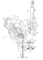
図1は、スライドマルノコの一例を示す側面図、図2はその平面図で、スライドマルノコ1は、ベース2の後方(図1の左側)に、レバー4を備えたアーム3を左右方向へ夫々最大45°まで回転可能且つ任意の角度で固定可能に設け、アーム3の上端に設けた筒状のホルダ5に、一対のポール6,6を前後方向へスライド可能に遊挿して、ポール6,6の前端同士を連結する前端部7に、支軸8を介して本体9を上下方向へ回転可能に連結してなる。本体9には、右側に設けたモータ10の駆動で回転する円盤状の鋸刃11が備えられて、支軸8に設けられた図示しないトーションバネによって、本体9は常態で図1の上限位置に保持されている。12は本体9の操作用のハンドル、13は鋸刃11の安全カバーである。
Hereinafter, embodiments of the present invention will be described with reference to the drawings.
FIG. 1 is a side view showing an example of a slide maroon, FIG. 2 is a plan view thereof, and the slide marco 1 has an
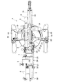
ベース2は、中央にターンベース14を回転可能に載置している。このターンベース14は、平面視が円形状で、前方には半径方向に延長部15が突設されて、その延長部15からターンベース14の中心に亘って上面に刃口板16が設けられている。アーム3はターンベース14の後面で後方に突設したアームホルダ17に連結されている。
また、ベース2において、ターンベース14の左右で上面が同一高さとなる載置部18,18間には、ガイドフェンス19が架設されている。このガイドフェンス19は、左右一対のガイド部20,20と、刃口板16を後方で迂回して両ガイド部20,20を連結する半円状の迂回部21とからなり、各ガイド部20が夫々載置部18にボルトで固定されている。
The
In the
そして、本体9において、支軸8寄りの左側面には、支持台22が突設され、その支持台22に、当接部材となる下限位置設定ボルト23が下向きに螺合されて、支軸8を中心とした本体9の上下動に伴い、下限位置設定ボルト23も支軸8を中心に円弧状に移動可能としている。24は、下限位置設定ボルト23と平行に支持台22に螺合された最下限位置設定ボルトで、その下端は下限位置設定ボルト23の下端よりも上方に位置しており、前端部7に設けたボルト受け25に当接する位置で、本体9の最下限が設定されるようになっている。
In the
一方、ホルダ5の左側面には、受け部材となるロッド26が設けられている。このロッド26は、ポール6,6の後端同士を連結する後端部27の側面と、ホルダ5の側面と、前端部7の側面とに夫々設けられた軸支部28,28・・によって、前端が下限位置設定ボルト23の下降軌跡上に位置する状態でポール6と平行且つ回転可能に軸支される軸体で、ホルダ5の軸支部28に対しては軸方向へ移動可能となっている。ロッド26の前端には、下限位置設定ボルト23の下端が当接可能な第1当接部位となる面取部29が設けられて、面取部29を除く前端を第2当接部位となる半円状の周面部30としている。このロッド26と本体9側の下限位置設定ボルト23とで下限ストッパ機構が形成されている。
On the other hand, a
また、図3にも示すように、ロッド26におけるホルダ5の側面部分には、上プーリ31が同軸且つ軸方向へ移動可能に設置され、アーム3の後面における傾動中心と同心位置(ハンドル4の貫通部分)には、下プーリ32が固定されて、上下プーリ31,32間に無端状のベルト33が張設されている。ここで、ロッド26の後方約半分の領域には面取りが形成され、上プーリ31におけるロッド26の貫通孔には、ロッド26の面取りに対応する平面部が形成されて、両者が相対回転しないようになっている。これにより、アーム3が左右方向へ傾動すると、固定される下プーリ32に対してベルト33が揺動しながら回転して上プーリ31を回転させ、ロッド26を上プーリ31と同時に回転させる連動手段が形成される。この連動手段とロッド26に形成した面取部29、周面部30とが本発明の切込深さ切換機構となる。
As shown in FIG. 3, the
この連動手段において、アーム3がターンベース14に対して直角となる直角切断位置では、図4(B)に示すようにロッド26は面取部29が上向きの位相(第1の位置)となる。また、アーム3がターンベース14に対して左方向に45°傾斜した位置では、同図(A)に示すようにロッド26は、ベルト33によって面取部29が左下向きの位相(第2の位置)となるまで前方に向かって左回転する。逆に、アーム3がターンベース14に対して右方向に45°傾斜した位置では、同図(C)に示すようにロッド26は、面取部29が右下向きの位相(第2の位置)となるまで前方に向かって右回転するようになっている。
In this interlocking means, when the
以上の如く構成されたスライドマルノコ1においては、アーム3がターンベース14に対して直角となる状態で、ターンベース14の上面に被切断材を載置し、ガイドフェンス19に押し当てて位置決めした状態で、ハンドル12を把持して本体9を下降させれば、図4(B)に示すように、本体9の下降に伴って下降した下限位置設定ボルト23の下端が、ロッド26の面取部29に当接するまで鋸刃11が下降し、直角切断を行うことができる。このときの鋸刃11は図1に示す下限位置Aとなる。
In the slide maroon 1 configured as described above, a material to be cut is placed on the upper surface of the
一方、傾斜切断を行う場合は、レバー4を緩めた状態で、ハンドル12を操作して本体9及びアーム3を左右何れかへ傾動させて、所望の角度でレバー4をねじ込んでアーム3を固定する。例えばアーム3を左側へ45°傾動させると、図4(A)に示すように、ベルト33を介してロッド26が左回転し、面取部29を左下へ向かせる。よって、この状態で本体9を下降させると、下限位置設定ボルト23の下端がロッド26の周面部30に当接する下限位置で本体9が停止する。このときの鋸刃11は図1に示す下限位置Bとなる。
逆にアーム3を右側へ45°傾動させると、同図(C)に示すように、ベルト33を介してロッド26が右回転し、面取部29を右下へ向かせる。よって、この状態で本体9を下降させると、下限位置設定ボルト23の下端がロッド26の周面部30に当接する下限位置で本体9が停止する。このときの鋸刃11も図1に示す下限位置Bとなる。
On the other hand, when performing inclined cutting, with the
Conversely, when the
こうして直角切断時と傾斜切断時とで鋸刃11の下限位置を変えて傾斜切断時の切込深さを直角切断時よりも浅くしたことで、刃口板16の上面で切り込まれる前後方向の長さが、直角切断の方で長くなる(図1のS部分)。よって、本体9を前後にスライドさせてスライド切断を行う場合には、鋸刃11の径が小さくても長いスライドストロークが確保できる。逆に、傾斜切断の場合には、切込深さが浅くなることで、本体9のモータ10等がガイドフェンス19等と干渉することなく、左右に最大45°ずつ傾斜可能となる。
In this way, the lower limit position of the
このように、上記形態のスライドマルノコ1によれば、本体9の傾動に連動し、傾斜切断時の切込深さを直角切断時の切込深さよりも浅くする切込深さ切換機構を設けたことで、直角切断時と傾斜切断時とでの切込深さが自動的に変更可能となり、使い勝手が向上する。而も、スライドストロークを大きくしなくてもスライド切断できる被切断材の前後寸法を十分確保できるため、全体のコンパクト化が期待できる。また、本体9の傾斜時にガイドフェンス19等と干渉するおそれがないため、傾斜切断の能力を損なうこともない。
As described above, according to the slide marnoco 1 of the above-described form, the cutting depth switching mechanism is provided that interlocks with the tilting of the
特にここでは、本体9に当接部材(下限位置設定ボルト23)を、ホルダ5に受け部材(ロッド26)を夫々設けて、切込深さ切換機構を、ロッド26に設けられ、直角切断時に下限位置設定ボルト23が当接する第1当接部位(面取部29)と、傾斜切断時に下限位置設定ボルト23が当接し、第1当接部位よりも鋸刃11の下限位置を高くする第2当接部位(周面部30)と、本体9の直角切断位置でロッド26を面取部29が下限位置設定ボルト23と当接する第1の位置に、傾斜切断位置でロッド26を周面部30が下限位置設定ボルト23と当接する第2の位置に夫々切換動作させる連動手段とから構成したことで、切込深さ切換機構が省スペースで簡単に得られ、切込深さの切換も確実に行える。
In particular, here, a contact member (lower limit position setting bolt 23) is provided on the
また、当接部材を、第1当接部位が面取部29、第2当接部位が周面部30となり、回転によって切換動作するロッド26としたことで、直角切断時と傾斜切断時との夫々の切込深さの設定が簡単に行える。
さらに、連動手段を、本体9の傾動中心で固定された下プーリ32と、ロッド26へ同軸に設けられた上プーリ31と、上下プーリ31,32間に張設された無端状のベルト33としたことで、本体9の傾動に連動してロッド26を第1、第2の位置へ夫々正確に回転させることができる。
In addition, the contact member is a
Further, the interlocking means includes a
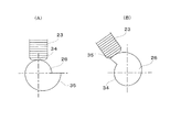
なお、ロッドの第1、第2当接部位は、先端でなく後端寄りに設けてもよいし、面取部と周面部とに限らず、鋸刃の下限位置を変更できれば凹部や段部等の他の形状で形成してもよい。また、図5に示すように、ロッド26の先端部を、中心から周面までの半径方向の距離が周方向へ行くに従って徐々に長くなるカム形状とし、第1当接部位を距離の短い第1周面部34、第2当接部位を第1周面部34よりも距離の長い第2周面部35として夫々直角時(同図(A))、傾斜時(同図(B))で下限位置を変更することもできる。このようにしても第1、第2当接部位が簡単に形成可能となる。
The first and second contact portions of the rod may be provided near the rear end instead of the front end, and are not limited to the chamfered portion and the peripheral surface portion. If the lower limit position of the saw blade can be changed, a concave portion or a stepped portion may be provided. You may form in other shapes, such as. Further, as shown in FIG. 5, the distal end of the
さらに、連動手段も、プーリとベルトとに代えて、スプロケットとチェーン、複数のギヤ等が採用できる。
但し、当接部材としてはロッドに限らず、連動手段によって当接部材との当接部位を切換動作できるものであれば、水平回転するプレート等も採用できる。よって、連動手段も当接部材の形状に合わせて他の構造に代えることもできる。さらに、連動手段はアームの側方でなく内部に設けることも可能である。
Furthermore, the interlocking means can employ a sprocket, a chain, a plurality of gears, etc. instead of the pulley and the belt.
However, the abutting member is not limited to the rod, and a horizontally rotating plate or the like may be adopted as long as the abutting portion with the abutting member can be switched by the interlocking means. Therefore, the interlocking means can be replaced with another structure according to the shape of the contact member. Further, the interlocking means can be provided not on the side of the arm but inside.
その他、スライドマルノコの形態も適宜変更可能で、例えば本体は左右何れか一方へのみ傾動可能であっても差し支えないし、スライドの形態も、アームの下端をターンベースに対して前後方向のポールを介してスライド可能に連結したりしても差し支えない。また、ターンベースがないスライドマルノコであっても本発明は適用可能である。
In addition, the shape of the slide marnoco can be changed as appropriate, for example, the main body can be tilted only to the left or right, and the slide shape can also be changed via a pole in the front-rear direction with respect to the turn base. And can be slidably connected. Further, the present invention can be applied even to a slide maroon without a turn base.
1・・スライドマルノコ、2・・ベース、3・・アーム、4・・レバー、8・・支軸、9・・本体、11・・鋸刃、14・・ターンベース、16・・刃口板、22・・支持台、23・・下限位置設定ボルト、24・・最下限位置設定ボルト、26・・ロッド、29・・面取部、30・・周面部、31・・上プーリ、32・・下プーリ、33・・ベルト、34・・第1周面部、35・・第2周面部。 1 .... Slide Maruko, 2 .... Base, 3 .... Arm, 4 .... Lever, 8 .... Support shaft, 9 .... Main body, 11 .... Saw blade, 14 .... Turn base, 16 .... Blade plate , 22 .. Support base, 23 .. Lower limit position setting bolt, 24 .. Lower limit position setting bolt, 26 .. Rod, 29. -Lower pulley, 33 ... Belt, 34 ... First peripheral surface, 35 ... Second peripheral surface.
Claims (5)
前記本体の傾動に連動し、前記傾斜切断時の前記切込深さを前記直角切断時の前記切込深さよりも浅くする切込深さ切換機構を設けたことを特徴とするスライドマルノコ。 A main body having a saw blade that is rotated by a motor drive is provided above the base so that it can be moved up and down, tilted to at least one of the left and right sides, and slid back and forth. A slide maroon that allows the workpiece set on the base to be cut at right angles with a predetermined cutting depth by lowering, and allows the workpiece to be inclined and cut with a predetermined cutting depth by lowering the tilted main body. Because
In combination with the tilting of the main body, a slide mark saw provided with a cutting depth switching mechanism that makes the cutting depth at the time of the inclined cutting shallower than the cutting depth at the time of the right-angle cutting.
前記切込深さ切換機構を、前記受け部材に設けられ、前記直角切断時に前記当接部材が当接する第1当接部位と、前記傾斜切断時に前記当接部材が当接し、前記第1当接部位よりも前記鋸刃の下限位置を高くする第2当接部位と、
前記本体の直角切断位置で前記受け部材を前記第1当接部位が前記当接部材と当接する第1の位置に、前記傾斜切断位置で前記受け部材を前記第2当接部位が前記当接部材と当接する第2の位置に夫々切換動作させる連動手段と
から構成したことを特徴とする請求項1に記載のスライドマルノコ。 A contact member is provided on the main body, and a receiving member is provided on a portion that is fixed to the vertical movement of the main body, and the contact member comes into contact with the receiving member as the main body is lowered. As the depth of cut is set,
The depth-of-cut switching mechanism is provided on the receiving member, and the first abutting portion with which the abutting member abuts at the time of the right-angle cutting and the abutting member abuts at the time of the inclined cutting, so that the first contact A second abutting portion that makes the lower limit position of the saw blade higher than the contacting portion;
The receiving member is brought into a first position where the first abutting part comes into contact with the abutting member at a right-angle cutting position of the main body, and the second abutting part is brought into contact with the receiving member at the inclined cutting position. The slide maroon according to claim 1, characterized by comprising interlocking means for switching each to a second position in contact with the member.
Priority Applications (3)
| Application Number | Priority Date | Filing Date | Title |
|---|---|---|---|
| JP2008228891A JP5384886B2 (en) | 2008-09-05 | 2008-09-05 | Slide marnoco |
| CN2009101574996A CN101664828B (en) | 2008-09-05 | 2009-07-30 | Slide circular saw |
| US12/461,721 US8413562B2 (en) | 2008-09-05 | 2009-08-21 | Slide circular saw |
Applications Claiming Priority (1)
| Application Number | Priority Date | Filing Date | Title |
|---|---|---|---|
| JP2008228891A JP5384886B2 (en) | 2008-09-05 | 2008-09-05 | Slide marnoco |
Publications (2)
| Publication Number | Publication Date |
|---|---|
| JP2010058248A true JP2010058248A (en) | 2010-03-18 |
| JP5384886B2 JP5384886B2 (en) | 2014-01-08 |
Family
ID=41798098
Family Applications (1)
| Application Number | Title | Priority Date | Filing Date |
|---|---|---|---|
| JP2008228891A Expired - Fee Related JP5384886B2 (en) | 2008-09-05 | 2008-09-05 | Slide marnoco |
Country Status (3)
| Country | Link |
|---|---|
| US (1) | US8413562B2 (en) |
| JP (1) | JP5384886B2 (en) |
| CN (1) | CN101664828B (en) |
Cited By (3)
| Publication number | Priority date | Publication date | Assignee | Title |
|---|---|---|---|---|
| JP2013000838A (en) * | 2011-06-16 | 2013-01-07 | Makita Corp | Covering device for cutting machine, and cutting machine mounted with the same |
| TWI483799B (en) * | 2012-04-20 | 2015-05-11 | Rexon Ind Corp Ltd | Circular saw |
| CN104907629A (en) * | 2012-03-15 | 2015-09-16 | 力山工业股份有限公司 | Sawing machine with mobile unit |
Families Citing this family (6)
| Publication number | Priority date | Publication date | Assignee | Title |
|---|---|---|---|---|
| CN201824014U (en) * | 2010-06-28 | 2011-05-11 | 南京德朔实业有限公司 | Miter saw |
| JP5814137B2 (en) * | 2012-01-19 | 2015-11-17 | 株式会社マキタ | Cutting machine |
| CN103394754B (en) * | 2013-08-16 | 2015-08-12 | 宁波德丰动力科技有限公司 | Cutting machine |
| US20180133819A1 (en) * | 2016-11-11 | 2018-05-17 | Makita Corporation | Cutting device |
| CN110605746A (en) * | 2019-10-16 | 2019-12-24 | 惠州市精谷自动化科技有限公司 | Beveling machine |
| CN112848405B (en) * | 2021-02-07 | 2023-07-04 | 江阴市科诚技术有限公司 | Chamfering method of post-treatment production line of pultruded plates for wind power blade girder |
Citations (4)
| Publication number | Priority date | Publication date | Assignee | Title |
|---|---|---|---|---|
| JPH0577202A (en) * | 1990-03-05 | 1993-03-30 | Black & Decker Inc | Portable circular saw |
| JPH08252719A (en) * | 1995-03-16 | 1996-10-01 | Ishikawajima Harima Heavy Ind Co Ltd | Panel cutting-off device |
| JPH1134002A (en) * | 1997-07-23 | 1999-02-09 | Makita Corp | Lower limit stopper of circular sawing machine |
| JP2004330655A (en) * | 2003-05-08 | 2004-11-25 | Hitachi Koki Co Ltd | Portable electrical cutting machine |
Family Cites Families (9)
| Publication number | Priority date | Publication date | Assignee | Title |
|---|---|---|---|---|
| US754150A (en) * | 1903-09-30 | 1904-03-08 | Harry Lehrer | Combination bed, sofa, and chair. |
| JP2573057B2 (en) * | 1989-07-07 | 1997-01-16 | 株式会社マキタ | Tabletop circular saw machine |
| JP3247996B2 (en) * | 1991-11-05 | 2002-01-21 | 株式会社マキタ | Cutting machine |
| US5495784A (en) * | 1994-09-29 | 1996-03-05 | Chen; Ruey-Zon | Cutting depth setting device for a saw machine |
| US7044041B1 (en) * | 2000-03-13 | 2006-05-16 | Black & Decker Inc. | Miter saw |
| JP4254429B2 (en) * | 2003-08-28 | 2009-04-15 | 日立工機株式会社 | Tabletop slide cutting machine |
| JP4563103B2 (en) * | 2004-08-04 | 2010-10-13 | 株式会社マキタ | Inclination positioning mechanism of cutting machine |
| US8359959B2 (en) * | 2008-01-08 | 2013-01-29 | Makita Corporation | Cutting devices |
| JP2013508399A (en) * | 2009-10-21 | 2013-03-07 | ヘルス リサーチ インコーポレイテッド | PAA nanoparticles for enhanced tumor imaging |
-
2008
- 2008-09-05 JP JP2008228891A patent/JP5384886B2/en not_active Expired - Fee Related
-
2009
- 2009-07-30 CN CN2009101574996A patent/CN101664828B/en not_active Expired - Fee Related
- 2009-08-21 US US12/461,721 patent/US8413562B2/en not_active Expired - Fee Related
Patent Citations (4)
| Publication number | Priority date | Publication date | Assignee | Title |
|---|---|---|---|---|
| JPH0577202A (en) * | 1990-03-05 | 1993-03-30 | Black & Decker Inc | Portable circular saw |
| JPH08252719A (en) * | 1995-03-16 | 1996-10-01 | Ishikawajima Harima Heavy Ind Co Ltd | Panel cutting-off device |
| JPH1134002A (en) * | 1997-07-23 | 1999-02-09 | Makita Corp | Lower limit stopper of circular sawing machine |
| JP2004330655A (en) * | 2003-05-08 | 2004-11-25 | Hitachi Koki Co Ltd | Portable electrical cutting machine |
Cited By (3)
| Publication number | Priority date | Publication date | Assignee | Title |
|---|---|---|---|---|
| JP2013000838A (en) * | 2011-06-16 | 2013-01-07 | Makita Corp | Covering device for cutting machine, and cutting machine mounted with the same |
| CN104907629A (en) * | 2012-03-15 | 2015-09-16 | 力山工业股份有限公司 | Sawing machine with mobile unit |
| TWI483799B (en) * | 2012-04-20 | 2015-05-11 | Rexon Ind Corp Ltd | Circular saw |
Also Published As
| Publication number | Publication date |
|---|---|
| US20100058910A1 (en) | 2010-03-11 |
| CN101664828A (en) | 2010-03-10 |
| JP5384886B2 (en) | 2014-01-08 |
| CN101664828B (en) | 2011-09-28 |
| US8413562B2 (en) | 2013-04-09 |
Similar Documents
| Publication | Publication Date | Title |
|---|---|---|
| JP5384886B2 (en) | Slide marnoco | |
| JP2005279933A5 (en) | ||
| JP2005279934A5 (en) | ||
| JP2008221812A (en) | Table cutter | |
| JP2005074695A (en) | Bench slide cutter | |
| US20120318112A1 (en) | Covering device for cutting machine and cutting machine having the same | |
| JP2010280012A (en) | Flip-over saw | |
| US9533361B2 (en) | Cutting machines | |
| JP2009126059A (en) | Vice device and cutter | |
| JP2010005750A (en) | Desktop cutter | |
| JP5184017B2 (en) | Positioning device for rotary table in tabletop circular saw | |
| JP6274522B2 (en) | Cutting machine | |
| EP2436494B1 (en) | Cutting machine with a safety cover | |
| JP5391840B2 (en) | Tabletop cutting machine | |
| JP2012157931A (en) | Desk top cutting machine | |
| JP2004142105A (en) | Inclined stopper device for cutting machine | |
| JP2006044066A (en) | Flip-over saw | |
| JP5344891B2 (en) | Inclined support mechanism of the main body of the cutting machine in the tabletop cutting machine | |
| WO2013108462A1 (en) | Cutting machine | |
| JP4943962B2 (en) | Slide type cutting machine | |
| JP2006044070A (en) | Flip-over saw | |
| JP2009149039A (en) | Bench cutting machine | |
| JP2009023035A (en) | Sliding type cutter and its assembling method | |
| JP2010076059A (en) | Portable cutting machine | |
| JP2008100355A (en) | Slide type bench cutter |
Legal Events
| Date | Code | Title | Description |
|---|---|---|---|
| A621 | Written request for application examination |
Free format text: JAPANESE INTERMEDIATE CODE: A621 Effective date: 20110318 |
|
| A131 | Notification of reasons for refusal |
Free format text: JAPANESE INTERMEDIATE CODE: A131 Effective date: 20130129 |
|
| A977 | Report on retrieval |
Free format text: JAPANESE INTERMEDIATE CODE: A971007 Effective date: 20130131 |
|
| A521 | Request for written amendment filed |
Free format text: JAPANESE INTERMEDIATE CODE: A523 Effective date: 20130305 |
|
| TRDD | Decision of grant or rejection written | ||
| A01 | Written decision to grant a patent or to grant a registration (utility model) |
Free format text: JAPANESE INTERMEDIATE CODE: A01 Effective date: 20130903 |
|
| A61 | First payment of annual fees (during grant procedure) |
Free format text: JAPANESE INTERMEDIATE CODE: A61 Effective date: 20131003 |
|
| R150 | Certificate of patent or registration of utility model |
Free format text: JAPANESE INTERMEDIATE CODE: R150 |
|
| LAPS | Cancellation because of no payment of annual fees |