WO2013108462A1 - Cutting machine - Google Patents
Cutting machine Download PDFInfo
- Publication number
- WO2013108462A1 WO2013108462A1 PCT/JP2012/077969 JP2012077969W WO2013108462A1 WO 2013108462 A1 WO2013108462 A1 WO 2013108462A1 JP 2012077969 W JP2012077969 W JP 2012077969W WO 2013108462 A1 WO2013108462 A1 WO 2013108462A1
- Authority
- WO
- WIPO (PCT)
- Prior art keywords
- unit
- main body
- cutting machine
- machine according
- blade
- Prior art date
Links
Images


Classifications
-
- B—PERFORMING OPERATIONS; TRANSPORTING
- B23—MACHINE TOOLS; METAL-WORKING NOT OTHERWISE PROVIDED FOR
- B23D—PLANING; SLOTTING; SHEARING; BROACHING; SAWING; FILING; SCRAPING; LIKE OPERATIONS FOR WORKING METAL BY REMOVING MATERIAL, NOT OTHERWISE PROVIDED FOR
- B23D47/00—Sawing machines or sawing devices working with circular saw blades, characterised only by constructional features of particular parts
- B23D47/02—Sawing machines or sawing devices working with circular saw blades, characterised only by constructional features of particular parts of frames; of guiding arrangements for work-table or saw-carrier
-
- B—PERFORMING OPERATIONS; TRANSPORTING
- B23—MACHINE TOOLS; METAL-WORKING NOT OTHERWISE PROVIDED FOR
- B23D—PLANING; SLOTTING; SHEARING; BROACHING; SAWING; FILING; SCRAPING; LIKE OPERATIONS FOR WORKING METAL BY REMOVING MATERIAL, NOT OTHERWISE PROVIDED FOR
- B23D45/00—Sawing machines or sawing devices with circular saw blades or with friction saw discs
- B23D45/04—Sawing machines or sawing devices with circular saw blades or with friction saw discs with a circular saw blade or the stock carried by a pivoted lever
- B23D45/042—Sawing machines or sawing devices with circular saw blades or with friction saw discs with a circular saw blade or the stock carried by a pivoted lever with the saw blade carried by a pivoted lever
- B23D45/044—Sawing machines or sawing devices with circular saw blades or with friction saw discs with a circular saw blade or the stock carried by a pivoted lever with the saw blade carried by a pivoted lever the saw blade being adjustable according to angle of cut
-
- B—PERFORMING OPERATIONS; TRANSPORTING
- B27—WORKING OR PRESERVING WOOD OR SIMILAR MATERIAL; NAILING OR STAPLING MACHINES IN GENERAL
- B27B—SAWS FOR WOOD OR SIMILAR MATERIAL; COMPONENTS OR ACCESSORIES THEREFOR
- B27B5/00—Sawing machines working with circular or cylindrical saw blades; Components or equipment therefor
- B27B5/16—Saw benches
- B27B5/18—Saw benches with feedable circular saw blade, e.g. arranged on a carriage
- B27B5/188—Saw benches with feedable circular saw blade, e.g. arranged on a carriage the saw blade being mounted on a hanging arm or at the end of a set of bars, e.g. parallelograms
-
- Y—GENERAL TAGGING OF NEW TECHNOLOGICAL DEVELOPMENTS; GENERAL TAGGING OF CROSS-SECTIONAL TECHNOLOGIES SPANNING OVER SEVERAL SECTIONS OF THE IPC; TECHNICAL SUBJECTS COVERED BY FORMER USPC CROSS-REFERENCE ART COLLECTIONS [XRACs] AND DIGESTS
- Y10—TECHNICAL SUBJECTS COVERED BY FORMER USPC
- Y10T—TECHNICAL SUBJECTS COVERED BY FORMER US CLASSIFICATION
- Y10T83/00—Cutting
- Y10T83/768—Rotatable disc tool pair or tool and carrier
- Y10T83/7684—With means to support work relative to tool[s]
- Y10T83/7693—Tool moved relative to work-support during cutting
- Y10T83/7697—Tool angularly adjustable relative to work-support
Definitions
- the present invention relates to a cutting machine such as a tabletop circular saw.
- a main body having a cutting blade that is rotated by a motor is provided on a base on which a material to be cut is placed so as to be movable up and down.
- the cutting material can be cut (for example, Patent Document 1).
- the cutting ability dimension in the front-rear direction of the material to be cut (cutting width)
- the diameter of the cutting blade in order to be able to cope with a material to be cut having a large cutting width.
- a cutting machine in which the main body can be slid in the front-rear direction such as a slide maroon disclosed in Patent Document 2 is also known.
- an object of the present invention is to provide a cutting machine capable of obtaining a high cutting ability with a simple configuration capable of maintaining compactness and low cost.
- the invention described in claim 1 is a cutting machine, a base, and a main body provided with a cutting blade provided so as to be movable up and down above the base and rotating by motor drive,
- the unit from the motor to the cutting blade is separated into a separate body within the main body, and the unit is held within the main body so as to be movable in the front-rear direction at the lower limit position of the main body. is there.
- the unit in the configuration of the first aspect, the unit is provided with a handle so that the unit can be moved in the front-rear direction in conjunction with an up / down operation of the handle.
- the invention according to claim 3 is characterized in that, in the configuration of claim 1 or 2, the unit is held in the main body by being pivotally attached to a main body portion other than the unit so as to be swingable in the front-rear direction.
- biasing means for biasing the unit to the front swing position is provided.
- the handle protrudes forward from the unit.
- a wide cutting width can be obtained with a simple configuration in which only the unit is moved back and forth without sliding the entire main body in the front and back direction. Therefore, a high cutting ability can be secured even with a small cutting blade, compactness can be maintained, and cost increase can be suppressed.
- the unit in addition to the effect of the first aspect, can be moved in the front-rear direction by the handle with good operability.
- the unit in addition to the effect of the first or second aspect, the unit can be moved back and forth with a simpler structure by axial attachment.
- the unit in addition to the effect of the third aspect, can be integrally fixed in the main body in a normal state by the biasing means, so that it does not hinder normal use.
- the unit in addition to the effect of the second aspect, can be easily swung back by the handle.
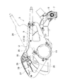
- FIG. 1 is a left side view of a tabletop circular saw machine which is an example of a cutting machine.
- the tabletop circular saw machine 1 is mounted on a base 2 so that a turntable 3 whose upper surface is the same height as the base 2 can be rotated horizontally.
- the arm 4 is erected on the rear end of the turntable 3 (the right side in FIG. 1 is the front) and is rotatable about the front / rear axis.
- the main body 5 is rotatably mounted on the shaft 6. However, the main body 5 is normally urged to the upper limit position shown in FIG. 1 by a torsion spring 7 (FIG. 4) provided on the support shaft 6.
- Reference numeral 8 denotes a guide fence which is erected on the base 2 in the left-right direction and used for positioning the workpiece W.
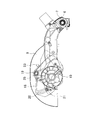
- the main body 5 includes a blade case 9 whose rear end is pivotally attached to the support shaft 6, a cylindrical gear housing 10 that is laterally connected to the side surface of the blade case 9, and the gear housing. And a cylindrical motor housing 11 connected to 10.
- a motor 12 in which an output shaft 13 projects into the gear housing 10 is accommodated in the motor housing 11, and a spindle 14 having a gear 15 that meshes with the output shaft 13 is accommodated in the gear housing 10. And protrudes into the blade case 9.
- a disc-shaped saw blade 16 as a cutting blade is mounted on the tip of the spindle 14 in an orthogonal shape.
- the gear housing 10 has a boss 17 projecting above the side surface of the blade case 6 and a flange portion 18 provided around the upper portion of the gear housing 10 so that it can be rotated by a bolt 19. It is connected to the blade case 6 by wearing. Thereby, the unit U from the motor 12 to the saw blade 16 in the main body 5 can swing back and forth around the bolt 19 with respect to the blade case 6.
- an arcuate guide groove 20 centered on the bolt 19 is formed in the flange portion 18, and a regulation bolt 21 penetrating the guide groove 20 is provided on the blade case 6. It is screwed into a small boss 22 protruding from the side. Therefore, the unit U is held so as to be swingable within a range in which the regulating bolt 21 contacts both ends of the guide groove 20.
- the boss 17 is provided with a torsion spring 25 as an urging means for engaging one end with the locking projection 23 on the blade case 6 side and the other end with the locking projection 24 on the flange portion 18 side, Normally, the unit U is urged to the front swing position (solid line position shown in FIG. 4) where the regulating bolt 21 abuts the lower end of the guide groove 20.
- Reference numeral 26 denotes a handle that is connected orthogonally to the upper peripheral surface of the motor housing 11, and a grip portion 27 is formed at the front end of the handle 26 that is positioned in front of the bolt 19 that is the pivot center. .
- the grip portion 27 includes a switch 28 and a switch lever 29 that turns on the switch 28 by a pushing operation.
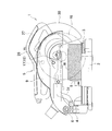
- the blade case 6 is rotatably provided with a safety cover 30 that covers the lower portion of the saw blade 16 at the upper limit position of the main body 5.
- the safety cover 30 rotates in a direction in which the saw blade 16 is opened by engaging with a link plate 31 provided between the safety cover 30 and the arm 4 as the main body 5 is lowered.
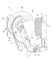
- the handle 26 is directed downward against the urging of the torsion spring 25 in a state where the grip portion 27 of the handle 26 is gripped and the main body 5 is lowered to the lower limit position.
- the unit U swings backward with respect to the blade case 6 with the bolt 19 as the center, so that the saw blade 16 also moves the bolt 19 from the front position indicated by a two-dot chain line a as shown in FIG. It swings backward while moving the center on the circular arc locus centered on.
- the regulation bolt 21 comes into contact with the upper end of the guide groove 20, the saw blade 16 reaches a rear position indicated by a two-dot chain line b. That is, the saw blade 16 can be moved in an arc from the front position to the rear position.
- the safety cover 30 is moved forward as shown in FIG. Since the saw blade 16 is released by rotating to the position, the exposed saw blade 16 can be cut into the workpiece W. If the lowering of the main body 5 is continued as it is, the main body 5 reaches the lower limit position and the saw blade 16 is cut beyond the workpiece W as shown in FIG. However, if the material W to be cut has a long dimension in the front-rear direction, an uncut portion remains in the rear portion in this state. Therefore, if the handle 26 is rotated downward from here to swing the unit U backward as described above, the saw blade 16 also swings backward together with the unit U, as shown in FIG. Cutting is also performed in the portion, and the workpiece W can be completely cut.
- the unit U from the motor 12 to the saw blade 16 is separated into a separate body within the main body 5, and the unit U is moved back and forth at the lower limit position of the main body 5. Since the main body 5 is held in the main body 5 so as to be swingable in the direction, the cutting width can be widened with a simple configuration in which only the unit U is swung without sliding the whole main body 5 in the front-rear direction. Therefore, even with a small saw blade 16, high cutting ability can be secured, compactness can be maintained, and cost increase can be suppressed.
- the unit U is provided with a handle 26 so that the unit U can be moved in the front-rear direction in conjunction with the up-and-down operation of the handle 26. Can be done. Further, the unit U is held in the main body 5 by being pivotally attached to the main body 5 portion (blade case 9) other than the unit U so as to be swingable in the front-rear direction, so that the unit U has a simpler configuration. It can be moved back and forth.
- the urging means for urging the unit U to the front swing position is provided, the unit U can be fixed integrally in the main body 5 in a normal state, which hinders normal use. Does not reach. Then, by causing the handle 26 to protrude forward from the unit U, the swinging operation of the unit U to the rear can be easily performed.
- the unit can be swung back and forth by pivotally mounting the unit with respect to the blade case.
- a long hole in the front-rear direction is formed in the flange portion of the gear housing. You may make it hold
- the units are not limited to be connected by bolts, and the blade case and the unit can be connected by a link mechanism such as a parallel link to hold the unit so as to be movable back and forth.
- a coil spring, a leaf spring, or the like can be appropriately employed as the biasing means.
- the present invention can be applied not only to a tabletop circular saw machine but also to other cutting machines such as cutters. Of course, even a sliding marnoco does not hinder the application of the present invention.
Abstract
Description
このような切断機は、切断刃の径によって切断能力(切断できる被切断材の前後方向の寸法(切断幅))が決まってしまうため、切断幅の大きい被切断材でも対応可能とすべく、例えば特許文献2に開示されるスライドマルノコのように、本体を前後方向へスライド可能とした切断機も知られている。 In a cutting machine such as a tabletop circular saw, a main body having a cutting blade that is rotated by a motor is provided on a base on which a material to be cut is placed so as to be movable up and down. The cutting material can be cut (for example, Patent Document 1).
In such a cutting machine, since the cutting ability (dimension in the front-rear direction of the material to be cut (cutting width)) is determined by the diameter of the cutting blade, in order to be able to cope with a material to be cut having a large cutting width, For example, a cutting machine in which the main body can be slid in the front-rear direction, such as a slide maroon disclosed in
請求項2に記載の発明は、請求項1の構成において、ユニットにハンドルを設けて、ハンドルの上下操作に連動してユニットを前後方向へ移動可能としたことを特徴とするものである。
請求項3に記載の発明は、請求項1又は2の構成において、ユニットを、当該ユニット以外の本体部分に前後方向へ揺動可能に軸着することで本体内で保持させたことを特徴とするものである。
請求項4に記載の発明は、請求項3の構成において、ユニットを前側の揺動位置へ付勢する付勢手段を設けたことを特徴とするものである。
請求項5に記載の発明は、請求項2の構成において、ハンドルを、ユニットよりも前方へ突出させたことを特徴とするものである。 In order to achieve the above object, the invention described in
According to a second aspect of the present invention, in the configuration of the first aspect, the unit is provided with a handle so that the unit can be moved in the front-rear direction in conjunction with an up / down operation of the handle.
The invention according to
According to a fourth aspect of the present invention, in the configuration of the third aspect of the present invention, biasing means for biasing the unit to the front swing position is provided.
According to a fifth aspect of the present invention, in the configuration of the second aspect, the handle protrudes forward from the unit.
請求項2に記載の発明によれば、請求項1の効果に加えて、ハンドルによってユニットの前後方向への移動を良好な操作性で行うことができる。
請求項3に記載の発明によれば、請求項1又は2の効果に加えて、軸着によってユニットをより簡単な構成で前後移動させることができる。
請求項4に記載の発明によれば、請求項3の効果に加えて、付勢手段により、常態ではユニットを本体内で一体的に固定できるため、通常の使用には支障を及ぼさない。
請求項5に記載の発明によれば、請求項2の効果に加えて、ハンドルによってユニットの後方への揺動操作を楽に行うことができる。 According to the first aspect of the present invention, a wide cutting width can be obtained with a simple configuration in which only the unit is moved back and forth without sliding the entire main body in the front and back direction. Therefore, a high cutting ability can be secured even with a small cutting blade, compactness can be maintained, and cost increase can be suppressed.
According to the second aspect of the invention, in addition to the effect of the first aspect, the unit can be moved in the front-rear direction by the handle with good operability.
According to the third aspect of the present invention, in addition to the effect of the first or second aspect, the unit can be moved back and forth with a simpler structure by axial attachment.
According to the fourth aspect of the present invention, in addition to the effect of the third aspect, the unit can be integrally fixed in the main body in a normal state by the biasing means, so that it does not hinder normal use.
According to the fifth aspect of the present invention, in addition to the effect of the second aspect, the unit can be easily swung back by the handle.
図1は、切断機の一例である卓上丸鋸盤の左側面図で、卓上丸鋸盤1は、ベース2上に、上面がベース2と同じ高さとなるターンテーブル3を水平回転可能に載置して、ターンテーブル3の後端(図1の右側を前方とする。)に、前後方向の軸を中心に回転可能なアーム4を立設し、アーム4の上端に、左右方向の支軸6によって本体5を回転可能に軸着してなる。但し、支軸6に設けたトーションスプリング7(図4)により、本体5は、常態では図1に示す上限位置へ付勢される。8は、ベース2上で左右方向に立設されて被切断材Wの位置決めに使用されるガイドフェンスである。 Hereinafter, embodiments of the present invention will be described with reference to the drawings.
FIG. 1 is a left side view of a tabletop circular saw machine which is an example of a cutting machine. The tabletop
さらに、ボス17には、一端がブレードケース6側の係止突起23に、他端がフランジ部18側の係止突起24にそれぞれ係止する付勢手段としてのトーションスプリング25が外装されて、常態ではユニットUを、規制ボルト21が案内溝20の下端に当接する前側の揺動位置(図4に示す実線位置)に付勢している。 4 and 5, an
Further, the
一方、ブレードケース6には、本体5の上限位置で鋸刃16の下方を覆う安全カバー30が回転可能に設けられている。この安全カバー30は、本体5の下降動作に伴い、アーム4との間に設けられたリンクプレート31との係合によって鋸刃16を開放させる方向へ回転するものである。
On the other hand, the
また、ユニットUを、当該ユニットU以外の本体5部分(ブレードケース9)に前後方向へ揺動可能に軸着することで本体5内で保持させたことで、ユニットUをより簡単な構成で前後移動させることができる。
さらに、ユニットUを前側の揺動位置へ付勢する付勢手段(トーションスプリング25)を設けているので、常態ではユニットUを本体5内で一体的に固定でき、通常の使用には支障を及ぼさない。
そして、ハンドル26を、ユニットUよりも前方へ突出させたことで、ユニットUの後方への揺動操作を楽に行うことができる。 In particular, here, the unit U is provided with a
Further, the unit U is held in the
In addition, since the urging means (torsion spring 25) for urging the unit U to the front swing position is provided, the unit U can be fixed integrally in the
Then, by causing the
その他、本発明は卓上丸鋸盤に限らず、カッタ等の他の切断機においても採用できる。勿論スライドマルノコであっても本発明の適用を妨げるものではない。 In the above embodiment, the unit can be swung back and forth by pivotally mounting the unit with respect to the blade case. For example, a long hole in the front-rear direction is formed in the flange portion of the gear housing. You may make it hold | maintain a unit so that a linear movement is possible to the front-back direction by enabling a volt | bolt to slide along a long hole. In addition, the units are not limited to be connected by bolts, and the blade case and the unit can be connected by a link mechanism such as a parallel link to hold the unit so as to be movable back and forth. In these cases, a coil spring, a leaf spring, or the like can be appropriately employed as the biasing means.
In addition, the present invention can be applied not only to a tabletop circular saw machine but also to other cutting machines such as cutters. Of course, even a sliding marnoco does not hinder the application of the present invention.
Claims (10)
- 切断機であって、
ベースと、
前記ベースの上方で上下動可能に設けられ、モータ駆動で回転する切断刃を備えた本体と、を含み、
前記モータから前記切断刃に至るユニットを、前記本体内で別体に分離すると共に、前記ユニットを、前記本体の下限位置で前後方向へ移動可能に前記本体内で保持させたことを特徴とする切断機。 A cutting machine,
Base and
A main body provided with a cutting blade provided so as to be movable up and down above the base and rotating by motor drive,
The unit from the motor to the cutting blade is separated into a separate body in the main body, and the unit is held in the main body so as to be movable in the front-rear direction at the lower limit position of the main body. Cutting machine. - 前記ユニットにハンドルを設けて、前記ハンドルの上下操作に連動して前記ユニットを前後方向へ移動可能としたことを特徴とする請求項1に記載の切断機。 The cutting machine according to claim 1, wherein a handle is provided on the unit, and the unit can be moved in the front-rear direction in conjunction with an up-and-down operation of the handle.
- 前記ユニットを、当該ユニット以外の本体部分に前後方向へ揺動可能に軸着することで前記本体内で保持させたことを特徴とする請求項1又は2に記載の切断機。 The cutting machine according to claim 1 or 2, wherein the unit is held in the main body by being pivotally attached to a main body portion other than the unit so as to be swingable in the front-rear direction.
- 前記ユニットを前側の揺動位置へ付勢する付勢手段を設けたことを特徴とする請求項3に記載の切断機。 4. The cutting machine according to claim 3, further comprising an urging means for urging the unit to a front swing position.
- 前記ハンドルを、前記ユニットよりも前方へ突出させたことを特徴とする請求項2に記載の切断機。 3. The cutting machine according to claim 2, wherein the handle protrudes forward from the unit.
- 前記ユニット側に、当該ユニットが軸着される軸を中心とした円弧状の案内溝を形成し、この案内溝を貫通する規制ボルトを、当該ユニット以外の本体部分に螺合させることで、前記ユニットを、前記規制ボルトが前記案内溝の両端に当接する範囲で揺動可能に保持させたことを特徴とする請求項3に記載の切断機。 On the unit side, an arc-shaped guide groove centered on an axis on which the unit is mounted is formed, and a regulation bolt that penetrates the guide groove is screwed to a main body portion other than the unit, 4. The cutting machine according to claim 3, wherein the unit is held so as to be swingable within a range in which the restriction bolt contacts both ends of the guide groove.
- 前記ユニット以外の本体部分は、前記切断刃を覆うブレードケースであることを特徴とする請求項1に記載の切断機。 The cutting machine according to claim 1, wherein the main body portion other than the unit is a blade case that covers the cutting blade.
- 前記付勢手段はトーションスプリングであることを特徴とする請求項4に記載の切断機。 The cutting machine according to claim 4, wherein the biasing means is a torsion spring.
- 前記ハンドルの前端にグリップ部を形成したことを特徴とする請求項5に記載の切断機。 The cutting machine according to claim 5, wherein a grip portion is formed at a front end of the handle.
- 前記ブレードケースに、前記本体の上限位置で前記切断刃の下方を覆う安全カバーを設けたことを特徴とする請求項7に記載の切断機。 The cutting machine according to claim 7, wherein a safety cover that covers a lower portion of the cutting blade at an upper limit position of the main body is provided on the blade case.
Priority Applications (3)
| Application Number | Priority Date | Filing Date | Title |
|---|---|---|---|
| US14/361,101 US20140331840A1 (en) | 2012-01-19 | 2012-10-30 | Cutting machine |
| CN201280066212.9A CN104039489B (en) | 2012-01-19 | 2012-10-30 | Cutting machine |
| DE112012005717.1T DE112012005717B4 (en) | 2012-01-19 | 2012-10-30 | cutting machine |
Applications Claiming Priority (2)
| Application Number | Priority Date | Filing Date | Title |
|---|---|---|---|
| JP2012009165A JP5814137B2 (en) | 2012-01-19 | 2012-01-19 | Cutting machine |
| JP2012-009165 | 2012-01-19 |
Publications (1)
| Publication Number | Publication Date |
|---|---|
| WO2013108462A1 true WO2013108462A1 (en) | 2013-07-25 |
Family
ID=48798899
Family Applications (1)
| Application Number | Title | Priority Date | Filing Date |
|---|---|---|---|
| PCT/JP2012/077969 WO2013108462A1 (en) | 2012-01-19 | 2012-10-30 | Cutting machine |
Country Status (5)
| Country | Link |
|---|---|
| US (1) | US20140331840A1 (en) |
| JP (1) | JP5814137B2 (en) |
| CN (1) | CN104039489B (en) |
| DE (1) | DE112012005717B4 (en) |
| WO (1) | WO2013108462A1 (en) |
Families Citing this family (2)
| Publication number | Priority date | Publication date | Assignee | Title |
|---|---|---|---|---|
| US8361067B2 (en) | 2002-09-30 | 2013-01-29 | Relievant Medsystems, Inc. | Methods of therapeutically heating a vertebral body to treat back pain |
| CN109129805A (en) * | 2018-10-30 | 2019-01-04 | 东莞市春旭机械科技有限公司 | A kind of Furniture panel conveys cutting device for noodle production and its method automatically |
Citations (3)
| Publication number | Priority date | Publication date | Assignee | Title |
|---|---|---|---|---|
| JPH0724521U (en) * | 1993-10-04 | 1995-05-09 | 株式会社レヂトン | Compass arm cutting machine |
| JPH07285020A (en) * | 1994-04-18 | 1995-10-31 | Ryobi Ltd | Circular sawing machine |
| JP2008272893A (en) * | 2007-05-01 | 2008-11-13 | Hitachi Koki Co Ltd | Slide type bench cutting machine |
Family Cites Families (14)
| Publication number | Priority date | Publication date | Assignee | Title |
|---|---|---|---|---|
| US477756A (en) * | 1892-06-28 | Cut-off saw | ||
| US1830579A (en) * | 1930-01-30 | 1931-11-03 | Wappat Inc | Electric handsaw |
| US5257570A (en) * | 1990-07-16 | 1993-11-02 | Ryobi Limited | Circular saw unit |
| JP3277307B2 (en) * | 1995-06-08 | 2002-04-22 | 株式会社マキタ | Tabletop circular saw machine |
| US5937720A (en) * | 1995-08-10 | 1999-08-17 | Milwaukee Electric Tool Corporation | Lower blade guard actuating mechanism for a slide compound miter saw |
| US20070137452A1 (en) * | 2005-11-22 | 2007-06-21 | Oberheim Stephen C | Power miter saw with hinge linkage linear guides |
| JP2008100355A (en) * | 2006-10-17 | 2008-05-01 | Hitachi Koki Co Ltd | Slide type bench cutter |
| JP5384886B2 (en) * | 2008-09-05 | 2014-01-08 | 株式会社マキタ | Slide marnoco |
| US20100058909A1 (en) * | 2008-09-11 | 2010-03-11 | Shaodong Chen | Power tool |
| CN102275010B (en) * | 2008-12-18 | 2013-12-25 | 苏州宝时得电动工具有限公司 | Obliquely cutting saw |
| JP5666094B2 (en) * | 2009-01-30 | 2015-02-12 | 株式会社マキタ | Tabletop cutting machine |
| US8919235B2 (en) * | 2009-03-17 | 2014-12-30 | Hitachi Koki Co., Ltd. | Cutting apparatus |
| JP5530649B2 (en) * | 2009-03-26 | 2014-06-25 | 株式会社マキタ | Slide marnoco |
| JP2012055994A (en) * | 2010-09-07 | 2012-03-22 | Makita Corp | Guide fence, and cutting machine having the same |
-
2012
- 2012-01-19 JP JP2012009165A patent/JP5814137B2/en not_active Expired - Fee Related
- 2012-10-30 DE DE112012005717.1T patent/DE112012005717B4/en not_active Expired - Fee Related
- 2012-10-30 CN CN201280066212.9A patent/CN104039489B/en not_active Expired - Fee Related
- 2012-10-30 WO PCT/JP2012/077969 patent/WO2013108462A1/en active Application Filing
- 2012-10-30 US US14/361,101 patent/US20140331840A1/en not_active Abandoned
Patent Citations (3)
| Publication number | Priority date | Publication date | Assignee | Title |
|---|---|---|---|---|
| JPH0724521U (en) * | 1993-10-04 | 1995-05-09 | 株式会社レヂトン | Compass arm cutting machine |
| JPH07285020A (en) * | 1994-04-18 | 1995-10-31 | Ryobi Ltd | Circular sawing machine |
| JP2008272893A (en) * | 2007-05-01 | 2008-11-13 | Hitachi Koki Co Ltd | Slide type bench cutting machine |
Also Published As
| Publication number | Publication date |
|---|---|
| DE112012005717B4 (en) | 2017-04-06 |
| JP2013146821A (en) | 2013-08-01 |
| CN104039489A (en) | 2014-09-10 |
| JP5814137B2 (en) | 2015-11-17 |
| CN104039489B (en) | 2016-03-09 |
| DE112012005717T5 (en) | 2014-11-06 |
| US20140331840A1 (en) | 2014-11-13 |
Similar Documents
| Publication | Publication Date | Title |
|---|---|---|
| JP5120781B2 (en) | Portable cutting machine | |
| JP4600184B2 (en) | Guide and portable cutting tool provided with the same | |
| JP5835611B2 (en) | Sliding tabletop cutting machine | |
| JP5103083B2 (en) | Tabletop cutting machine | |
| JP5410843B2 (en) | Cutting machine | |
| JP2007223133A (en) | Portable cutting machine | |
| JP5290040B2 (en) | Cutting machine | |
| US9533361B2 (en) | Cutting machines | |
| JP5814137B2 (en) | Cutting machine | |
| JP4891105B2 (en) | Portable circular saw | |
| JP6274522B2 (en) | Cutting machine | |
| JP7103002B2 (en) | Cutting machine | |
| JP5391840B2 (en) | Tabletop cutting machine | |
| JP6274602B2 (en) | Tabletop cutting machine | |
| JP2012076192A (en) | Cutting machine | |
| JP2008100356A (en) | Slide type bench cutter | |
| JP5344891B2 (en) | Inclined support mechanism of the main body of the cutting machine in the tabletop cutting machine | |
| JP4529865B2 (en) | Band saw board | |
| JP6724491B2 (en) | Cutting machine | |
| JP2014195860A (en) | Portable cutting device | |
| JP5760602B2 (en) | Sliding tabletop cutting machine | |
| JP5915896B2 (en) | Tabletop cutting machine | |
| JP2008044034A (en) | Cutter | |
| JP4204749B2 (en) | Circular saw machine | |
| JP2017080869A (en) | Cutting machine |
Legal Events
| Date | Code | Title | Description |
|---|---|---|---|
| WWE | Wipo information: entry into national phase |
Ref document number: 201280066212.9 Country of ref document: CN |
|
| 121 | Ep: the epo has been informed by wipo that ep was designated in this application |
Ref document number: 12865996 Country of ref document: EP Kind code of ref document: A1 |
|
| WWE | Wipo information: entry into national phase |
Ref document number: 14361101 Country of ref document: US |
|
| WWE | Wipo information: entry into national phase |
Ref document number: 112012005717 Country of ref document: DE Ref document number: 1120120057171 Country of ref document: DE |
|
| 122 | Ep: pct application non-entry in european phase |
Ref document number: 12865996 Country of ref document: EP Kind code of ref document: A1 |