JP2010058212A - Grinding wheel - Google Patents
Grinding wheel Download PDFInfo
- Publication number
- JP2010058212A JP2010058212A JP2008225542A JP2008225542A JP2010058212A JP 2010058212 A JP2010058212 A JP 2010058212A JP 2008225542 A JP2008225542 A JP 2008225542A JP 2008225542 A JP2008225542 A JP 2008225542A JP 2010058212 A JP2010058212 A JP 2010058212A
- Authority
- JP
- Japan
- Prior art keywords
- wheel
- grinding
- grinding wheel
- mount
- wheel base
- Prior art date
- Legal status (The legal status is an assumption and is not a legal conclusion. Google has not performed a legal analysis and makes no representation as to the accuracy of the status listed.)
- Granted
Links
- 239000004696 Poly ether ether ketone Substances 0.000 claims description 6
- 229920002530 polyetherether ketone Polymers 0.000 claims description 6
- 229920006324 polyoxymethylene Polymers 0.000 claims description 6
- 239000011347 resin Substances 0.000 claims description 4
- 229920005989 resin Polymers 0.000 claims description 4
- 229930182556 Polyacetal Natural products 0.000 claims description 3
- 230000002093 peripheral effect Effects 0.000 abstract description 3
- WSMQKESQZFQMFW-UHFFFAOYSA-N 5-methyl-pyrazole-3-carboxylic acid Chemical compound CC1=CC(C(O)=O)=NN1 WSMQKESQZFQMFW-UHFFFAOYSA-N 0.000 description 3
- 238000010521 absorption reaction Methods 0.000 description 3
- 239000000853 adhesive Substances 0.000 description 3
- 230000001070 adhesive effect Effects 0.000 description 3
- 229920006351 engineering plastic Polymers 0.000 description 3
- 239000000463 material Substances 0.000 description 3
- 229910052594 sapphire Inorganic materials 0.000 description 3
- 239000010980 sapphire Substances 0.000 description 3
- 229910000838 Al alloy Inorganic materials 0.000 description 2
- 229910052581 Si3N4 Inorganic materials 0.000 description 2
- 238000003780 insertion Methods 0.000 description 2
- 230000037431 insertion Effects 0.000 description 2
- 229910052451 lead zirconate titanate Inorganic materials 0.000 description 2
- HFGPZNIAWCZYJU-UHFFFAOYSA-N lead zirconate titanate Chemical compound [O-2].[O-2].[O-2].[O-2].[O-2].[Ti+4].[Zr+4].[Pb+2] HFGPZNIAWCZYJU-UHFFFAOYSA-N 0.000 description 2
- 239000004065 semiconductor Substances 0.000 description 2
- HQVNEWCFYHHQES-UHFFFAOYSA-N silicon nitride Chemical compound N12[Si]34N5[Si]62N3[Si]51N64 HQVNEWCFYHHQES-UHFFFAOYSA-N 0.000 description 2
- 229910013641 LiNbO 3 Inorganic materials 0.000 description 1
- 239000006061 abrasive grain Substances 0.000 description 1
- 229910002113 barium titanate Inorganic materials 0.000 description 1
- JRPBQTZRNDNNOP-UHFFFAOYSA-N barium titanate Chemical compound [Ba+2].[Ba+2].[O-][Ti]([O-])([O-])[O-] JRPBQTZRNDNNOP-UHFFFAOYSA-N 0.000 description 1
- 230000005540 biological transmission Effects 0.000 description 1
- NEHMKBQYUWJMIP-UHFFFAOYSA-N chloromethane Chemical compound ClC NEHMKBQYUWJMIP-UHFFFAOYSA-N 0.000 description 1
- 238000009429 electrical wiring Methods 0.000 description 1
- GQYHUHYESMUTHG-UHFFFAOYSA-N lithium niobate Chemical compound [Li+].[O-][Nb](=O)=O GQYHUHYESMUTHG-UHFFFAOYSA-N 0.000 description 1
- 238000000034 method Methods 0.000 description 1
- 238000012986 modification Methods 0.000 description 1
- 230000004048 modification Effects 0.000 description 1
- 230000000149 penetrating effect Effects 0.000 description 1
- 230000001681 protective effect Effects 0.000 description 1
- XLYOFNOQVPJJNP-UHFFFAOYSA-N water Substances O XLYOFNOQVPJJNP-UHFFFAOYSA-N 0.000 description 1
Images


Abstract
Description
本発明は、半導体ウエーハ等の被加工物を研削するための研削装置に装着される研削ホイールに関する。 The present invention relates to a grinding wheel mounted on a grinding apparatus for grinding a workpiece such as a semiconductor wafer.
IC、LSI等の数多くのデバイスが表面に形成され、且つ個々のデバイスが分割予定ライン(ストリート)によって区画された半導体ウエーハは、研削装置によって裏面が研削されて所定の厚みに加工された後、切削装置(ダイシング装置)によって分割予定ラインを切削して個々のデバイスに分割され、分割されたデバイスは携帯電話、パソコン等の電気機器に利用される。 A semiconductor wafer in which a number of devices such as IC and LSI are formed on the surface, and each device is partitioned by a line to be divided (street), the back surface is ground by a grinding machine and processed to a predetermined thickness. A dividing line is cut by a cutting device (dicing device) to be divided into individual devices, and the divided devices are used for electric devices such as mobile phones and personal computers.
ウエーハの裏面を研削する研削装置は、ウエーハを保持するチャックテーブルと、該チャックテーブルに保持されたウエーハを研削する研削砥石を有する研削ホイールが回転可能に装着された研削手段とを備えていて、ウエーハを高精度に所望の厚みに研削できる。 A grinding apparatus for grinding a back surface of a wafer includes a chuck table for holding a wafer, and a grinding means on which a grinding wheel having a grinding wheel for grinding the wafer held on the chuck table is rotatably mounted. The wafer can be ground to a desired thickness with high accuracy.
ところで、サファイア、シリコンナイトライド、リチウムタンタレート、アルチック等の脆性硬質材料を研削装置で研削すると長時間を要し、生産性が悪いという問題があることから、本出願人は、超音波振動子を研削ホイールに配設して被加工物を研削する技術を開発し、特許出願した(特開2008−23693号公報)。
しかし、特許文献1に開示された研削ホイールの構造では、超音波振動子が生成する超音波振動が研削砥石に充分伝達しないという問題があることが判明した。 However, it has been found that the structure of the grinding wheel disclosed in Patent Document 1 has a problem that the ultrasonic vibration generated by the ultrasonic vibrator is not sufficiently transmitted to the grinding wheel.
本発明はこのような点に鑑みてなされたものであり、その目的とするところは、研削砥石に超音波振動子が生成する超音波振動を充分伝達可能な研削ホイールを提供することである。 The present invention has been made in view of these points, and an object of the present invention is to provide a grinding wheel that can sufficiently transmit ultrasonic vibration generated by an ultrasonic vibrator to a grinding wheel.
本発明によると、研削装置のスピンドル先端に固定されたホイールマウントに装着される研削ホイールであって、該ホイールマウントに装着されるマウント装着リングと、第1面及び該第1面と反対側の第2面を有し、複数の研削砥石が該第2面の外周部に固定されたホイールベースと、該研削砥石の半径方向内側で該ホイールベースの該第1面に配設された超音波振動子と、該マウント装着リングと該ホイールベースとの間に介装された振動吸収リングと、を具備したことを特徴とする研削ホイールが提供される。 According to the present invention, a grinding wheel is mounted on a wheel mount fixed to a spindle tip of a grinding apparatus, the mount mounting ring mounted on the wheel mount, a first surface, and a first surface and a side opposite to the first surface. A wheel base having a second surface, wherein a plurality of grinding wheels are fixed to the outer periphery of the second surface, and an ultrasonic wave disposed on the first surface of the wheel base radially inward of the grinding wheel There is provided a grinding wheel including a vibrator, and a vibration absorbing ring interposed between the mount mounting ring and the wheel base.
好ましくは、ホイールベースは第1面に環状溝を有しており、超音波振動子は該環状溝中に挿入固定されている。 Preferably, the wheel base has an annular groove on the first surface, and the ultrasonic transducer is inserted and fixed in the annular groove.
好ましくは、前記振動吸収リングは、該ホイールベースに連結される第1の連結部と、該マウント装着リングに連結される第2の連結部と、該第1の連結部と該第2の連結部との間に形成され、該ホイールベースに生成された超音波振動を吸収するスリット部とを有している。 Preferably, the vibration absorbing ring includes a first connecting part connected to the wheel base, a second connecting part connected to the mount mounting ring, the first connecting part, and the second connection. And a slit portion that absorbs ultrasonic vibration generated in the wheel base.
更に好ましくは、前記振動吸収リングは、ポリエーテルエーテルケトン(PEEK)又はポリアセタール(POM)の何れかである硬質樹脂から形成される。 More preferably, the vibration absorbing ring is formed of a hard resin that is either polyetheretherketone (PEEK) or polyacetal (POM).
本発明によると、複数の研削砥石が固定された面と反対側のホイールベースの面上で且つ研削砥石の内側に超音波振動子を配設するとともに、研削砥石と超音波振動子とが固定されたホイールベースを振動吸収リングを介してマウント装着リングに取り付けたので、超音波振動子が生成した超音波振動が振動吸収リングで吸収されてホイールマウントに伝達されることが抑制され、超音波振動を研削砥石に充分伝達することができ、効率良くサファイア等の脆性硬質材料を研削することができる。 According to the present invention, the ultrasonic vibrator is disposed on the surface of the wheel base opposite to the surface on which the plurality of grinding wheels are fixed and inside the grinding wheel, and the grinding wheel and the ultrasonic vibrator are fixed. Since the mounted wheel base is attached to the mount mounting ring via the vibration absorption ring, the ultrasonic vibration generated by the ultrasonic vibrator is suppressed from being absorbed by the vibration absorption ring and transmitted to the wheel mount. Vibration can be sufficiently transmitted to the grinding wheel, and brittle hard materials such as sapphire can be ground efficiently.
以下、本発明の実施形態を図面を参照して詳細に説明する。図1は本発明実施形態の研削ホイールを具備した研削装置2の外観斜視図を示している。4は研削装置2のハウジングであり、ハウジング4の後方にはコラム6が立設されている。コラム6には、上下方向に伸びる一対のガイドレール8が固定されている。
Hereinafter, embodiments of the present invention will be described in detail with reference to the drawings. FIG. 1 shows an external perspective view of a
この一対のガイドレール8に沿って研削ユニット(研削手段)10が上下方向に移動可能に装着されている。研削ユニット10は、スピンドルハウジング12と、スピンドルハウジング12を保持する支持部14を有しており、支持部14が一対のガイドレール8に沿って上下方向に移動する移動基台16に取り付けられている。
A grinding unit (grinding means) 10 is mounted along the pair of
研削ユニット10はスピンドルハウジング12中に回転可能に収容されたスピンドル18と、スピンドル18の先端に固定されたホイールマウント20と、ホイールマウント20にねじ締結され環状に配設された複数の研削砥石を有する研削ホイール22と、スピンドル18を回転駆動する電動モーターを含んでいる。
The
研削装置2は、研削ユニット10を一対の案内レール8に沿って上下方向に移動するボールねじ28とパルスモータ30とから構成される研削ユニット移動機構32を備えている。パルスモータ30を駆動すると、ボールねじ28が回転し、移動基台16が上下方向に移動される。
The
ハウジング4の上面には凹部4aが形成されており、この凹部4aにチャックテーブル機構34が配設されている。チャックテーブル機構34はチャックテーブル36を有し、図示しない移動機構によりウエーハ着脱位置Aと、研削ユニット10に対向する研削位置Bとの間でY軸方向に移動される。38,40は蛇腹である。ハウジング4の前方側には、研削装置2のオペレータが検索条件等を入力する操作パネル42が配設されている。
A
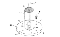
図2及び図3に示すように、スピンドル18の先端は小径先端部18aに形成されており、この小径先端部18aにホイールマウント20が固定されている。ホイールマウント20は4個の丸穴47を有しており、これらの丸穴47にボルト48を挿入して研削ホイール22のねじ穴にボルト48を螺合することにより、研削ホイール22がホイールマウント20に取り付けられる。
As shown in FIGS. 2 and 3, the tip of the
スピンドル18には、スピンドル18を上下方向に貫通する貫通孔21が形成されており、この貫通孔21の先端部は図3に示すように径が拡大されたコネクター挿入孔19が形成されている。コネクター挿入孔19中に凹型コネクター50が挿入されており、この凹型コネクター50に後で説明する超音波振動子に接続された凸型コネクター65が嵌合される。
The
図4を参照すると、本発明実施形態の研削ホイール22の分解斜視図が示されている。図5は研削ホイール22の斜視図、図6は研削ホイール22の一部断面正面図である。56は研削ホイール22のホイールベースであり、ホイールベース56の第2面即ち下面56b(図7参照)の外周には複数の研削砥石58が環状に固着されている。
Referring to FIG. 4, an exploded perspective view of the
図7に最も良く示されるように、ホイールベース56の第1面即ち上面56aには環状溝59が形成されており、この環状溝59中に環状の超音波振動子60が挿入されて接着剤等により固着されている。ホイールベース56は中心穴63を有している。超音波振動子60は複数の円弧状超音波振動子を環状溝59中に挿入固定するようにしても良い。
As best shown in FIG. 7, an
図7に示したホイールベース56の変形例として、ホイールベース56の上面56aに環状溝59を形成せずに、環状又は円弧状の超音波振動子60を接着力の強い接着剤によりホイールベース56の上面56a上に直接接着するようにしても良い。超音波振動子60に接続された一対の導電線61は図3に示した凸型コネクター65に接続されている。
As a modification of the
図4を再び参照すると、62はマウント装着リングであり、ボルト48が螺合される4個のねじ穴64と、4個の貫通穴66を有している。各貫通穴66の上部には締結ねじの頭部が挿入される座繰り66aが形成されている。
Referring again to FIG. 4,
68は振動吸収リングであり、例えばアルミニウム合金から形成されている。振動吸収リング68はホイールベース56に連結される第1の連結部68aと、マウント装着リング62に連結される第2の連結部68bと、第1の連結部68aと第2の連結部68bとの間に形成されたホイールベース56に生成された超音波振動を吸収する複数のスリット70を有している。振動吸収リング68は更に、マウント装着リング62の各貫通穴66に整列して締結ねじが螺合される4個のねじ穴72を有している。
研削ホイール22を組み立てるには、ホイールベース56を振動吸収リング68の第1の連結部68aに接着等により固定する。更に、マウント装着リング62の貫通穴66中に締結ねじを挿入し振動吸収リング68のねじ穴72に螺合することにより、振動吸収リング68を第2の連結部68bでマウント装着リング62に固定する。
In order to assemble the
これにより、図5及び図6に示すような研削ホイール22が得られる。マウント装着リング62を振動吸収リング68にねじ締結する代わりに、マウント装着リング62を振動吸収リング68に接着固定するようにしても良い。
Thereby, the
超音波振動子60としては、チタン酸バリウム(BaTiO3)、チタン酸ジルコン酸鉛(Pb(Zi,Ti)O3)、リチウムナイオベート(LiNbO3)、リチウムタンタレート(LiTaO3)を用いることができる。
As the
上述した実施形態では、振動吸収リング68をアルミニウム合金から形成した例について説明したが、振動吸収リング68としてエンジニアリングプラスチック(硬質樹脂)を採用するようにしても良い。エンジニアリングプラスチックは、例えばポリエーテルエーテルケトン(PEEK)又はポリアセタール(POM)の何れかから選択される。
In the above-described embodiment, the example in which the
振動吸収リング68をエンジニアリングプラスチックから形成した場合には、スリット70を特に設けなくてもホイールベース56に生成された超音波振動を吸収できるが、複数のスリット70を形成すると振動の吸収がより効果的である。
When the
図2を再び参照すると、研削ユニット10はスピンドル18を回転駆動する電動モーター74を備えている。電動モーター74は例えば永久磁石式モーターから構成される。電動モーター74は、スピンドル18の中間部に形成されたモーター装着部76に装着された永久磁石からなるローター78と、ローター78の外周側においてスピンドルハウジング12に配設されたステータコイル80とから構成される。
Referring back to FIG. 2, the grinding
このように構成された電動モーター74は、ステータコイル80に後述する電力供給手段によって交流電力を印加することによりローター78が回転し、ローター78が装着されたスピンドル18が回転される。
In the
研削ユニット10は更に、超音波振動子60に交流電力を印加するとともに電動モーター74に交流電力を印加する電力供給手段82を具備している。電力供給手段82は、スピンドル18の上端に配設されたロータリートランス84を含んでいる。
The grinding
ロータリートランス84は、スピンドル18の上端に配設された受電手段86と、受電手段86と対向して配設された給電手段88を具備している。受電手段86は、スピンドル18に装着されたローターコア90と、ローターコア90に巻回された受電コイル92とから構成される。
The
このように構成された受電手段86の受電コイル92には導電線52が接続されている。この導電線52は、スピンドル18の中心に軸方向に形成された貫通穴21内に配設され、その先端が図3に示す凹型コネクター50に接続されている。
A
給電手段88は、受電手段86の外周側に配設されたステータコア94と、ステータコア94に配設された給電コイル96とから構成される。このように構成された給電手段88の給電コイル96には、電気配線98を介して交流電力が供給される。
The
電力供給手段82は、交流電源100と、交流電源100とロータリートランス84の給電コイル96との間に挿入された電圧調整手段102と、給電手段88に供給する交流電力の周波数を調整する周波数調整手段104と、電圧調整手段102及び周波数調整手段104を制御する制御手段106と、制御手段106に研削砥石に付与する超音波振動の振幅等を入力する入力手段108を具備している。
The power supply means 82 is a frequency adjustment that adjusts the frequency of the AC power supplied to the
交流電源100は、制御回路112及び電気配線110を介して電動モーター74のステータコイル80に交流電力を供給する。周波数調整手段104としては、株式会社エヌエフ回路設計ブロックが提供するデジタルファンクションジェネレータ、商品名「DF−1905」を使用することができる。DF−1905によると、周波数を10Hz〜500kHzの範囲内で適宜調整することができる。
The
このように構成された研削装置2の研削作業について以下に説明する。図1に示すウエーハ着脱位置Aに位置付けられたチャックテーブル36上に、図8に示すように表面に保護テープTが貼付されたウエーハWを保護テープTを下にして吸引保持する。次いで、チャックテーブル36をY軸方向に移動して研削位置Bに位置付ける。
The grinding operation of the grinding
このように位置付けられたウエーハWに対して、図8に示すようにチャックテーブル36を矢印A方向に例えば300rpmで回転しつつ、研削ホイール22をチャックテーブル36と同一方向に、即ち矢印B方向に例えば6000rpmで回転駆動させるとともに、研削ユニット移動機構32を作動して研削砥石58をウエーハWの裏面に接触させる。
With respect to the wafer W positioned in this way, as shown in FIG. 8, while rotating the chuck table 36 in the direction of arrow A at, for example, 300 rpm, the grinding
この研削加工時には、電力供給手段82によってロータリートランス84を構成する給電手段88の給電コイル96に所定周波数の交流電力を供給する。その結果、回転する受電手段86の受電コイル92、導電線52、凹型コネクター50、凸型コネクター65、導電線61を介して超音波振動子60に所定周波数の交流電力が印加され、超音波振動子60は主にラジアル方向(径方向)に超音波振動する。この超音波振動は、ホイールベース56を介して複数の研削砥石58に伝達され、研削砥石58がラジアル方向に超音波振動する。
At the time of this grinding process, AC power of a predetermined frequency is supplied to the
本実施形態の研削ホイール22では、複数のスリット70を有する振動吸収リング68を介してホイールベース56がマウント装着リング6に取り付けられているため、超音波振動子60が発生する超音波振動のホイールマウント20への伝達が抑制される。従って、超音波振動子60から発生された超音波振動は、ホイールベース56を介して複数の研削砥石58に効果的に伝達される。
In the
このように超音波振動子60で研削砥石58を主にラジアル方向に振動させながら研削ホイール22を所定の研削送り速度(例えば3〜5μm/秒)で下方に所定量研削送りして、ウエーハWの研削を実施する。
In this way, the grinding
研削砥石58がラジアル方向に超音波振動すると、研削によって生成され研削砥石58の砥粒間に滞留して目詰まりの原因となる研削屑が、研削砥石58に作用する微振動により研削水とともに流動されて除去される。
When the
従って、研削砥石58の目詰まりを防止することができるため、サファイア、シリコンナイトライド、リチウムタンタレート、アルチック等の脆性硬質材料であっても効率良く研削することができる。
Therefore, since the clogging of the
(実施例)
超音波振動子60をチタン酸ジルコン酸鉛(Pb(Zi,Ti)O3)から形成した本発明実施形態の研削ホイール22をホイールマウント20に装着し、超音波振動子60に50kHzの周波数で150Vの電圧を印加した。
(Example)
The grinding
その結果、研削砥石58は50kHzの周波数でラジアル方向(径方向)に6μm前後の振幅で振動した。研削砥石58は軸方向にも超音波振動するが、軸方向への振幅は1.0μm前後でラジアル方向に比較して小さいものであった。
As a result, the grinding
尚、比較のために特許文献1に開示された研削ホイールをホイールマウントに装着し、実施例と同一条件で超音波振動子に交流電圧を印加したところ、研削砥石はラジアル方向に僅かに超音波振動したが、その振幅は0.2μm前後で充分な振幅は得られなかった。 For comparison, when the grinding wheel disclosed in Patent Document 1 was mounted on a wheel mount and an AC voltage was applied to the ultrasonic vibrator under the same conditions as in the example, the grinding wheel was slightly ultrasonic in the radial direction. Although it vibrated, its amplitude was around 0.2 μm, and sufficient amplitude was not obtained.
2 研削装置
10 研削ユニット
20 ホイールマウント
22 研削ホイール
36 チャックテーブル
56 ホイールベース
58 研削砥石
60 超音波振動子
62 マウント装着リング
68 振動吸収リング
70 スリット
2 Grinding
Claims (5)
該ホイールマウントに装着されるマウント装着リングと、
第1面及び該第1面と反対側の第2面を有し、複数の研削砥石が該第2面の外周部に固定されたホイールベースと、
該研削砥石の半径方向内側で該ホイールベースの該第1面に配設された超音波振動子と、
該マウント装着リングと該ホイールベースとの間に介装された振動吸収リングと、
を具備したことを特徴とする研削ホイール。 A grinding wheel mounted on a wheel mount fixed to a spindle tip of a grinding device,
A mount mounting ring mounted on the wheel mount;
A wheel base having a first surface and a second surface opposite to the first surface, wherein a plurality of grinding wheels are fixed to the outer periphery of the second surface;
An ultrasonic transducer disposed on the first surface of the wheel base radially inward of the grinding wheel;
A vibration absorbing ring interposed between the mount mounting ring and the wheel base;
A grinding wheel characterized by comprising:
Priority Applications (1)
| Application Number | Priority Date | Filing Date | Title |
|---|---|---|---|
| JP2008225542A JP5259307B2 (en) | 2008-09-03 | 2008-09-03 | Grinding wheel |
Applications Claiming Priority (1)
| Application Number | Priority Date | Filing Date | Title |
|---|---|---|---|
| JP2008225542A JP5259307B2 (en) | 2008-09-03 | 2008-09-03 | Grinding wheel |
Publications (2)
| Publication Number | Publication Date |
|---|---|
| JP2010058212A true JP2010058212A (en) | 2010-03-18 |
| JP5259307B2 JP5259307B2 (en) | 2013-08-07 |
Family
ID=42185605
Family Applications (1)
| Application Number | Title | Priority Date | Filing Date |
|---|---|---|---|
| JP2008225542A Active JP5259307B2 (en) | 2008-09-03 | 2008-09-03 | Grinding wheel |
Country Status (1)
| Country | Link |
|---|---|
| JP (1) | JP5259307B2 (en) |
Cited By (7)
| Publication number | Priority date | Publication date | Assignee | Title |
|---|---|---|---|---|
| JP2010058252A (en) * | 2008-09-08 | 2010-03-18 | Disco Abrasive Syst Ltd | Grinding wheel |
| JP2012016779A (en) * | 2010-07-08 | 2012-01-26 | Disco Corp | Machining method of lithium tantalate |
| JP2012125850A (en) * | 2010-12-13 | 2012-07-05 | Disco Corp | Grinding wheel |
| JP2014042947A (en) * | 2012-08-24 | 2014-03-13 | Disco Abrasive Syst Ltd | Grinding apparatus |
| CN108747715A (en) * | 2018-08-28 | 2018-11-06 | 艾尔发智能科技股份有限公司 | A kind of wet type automatically grinding polishing machine |
| CN109397086A (en) * | 2017-08-17 | 2019-03-01 | 株式会社迪思科 | Mounting base |
| KR20220060170A (en) * | 2020-11-04 | 2022-05-11 | 주식회사아일 | Conductor decoating tool |
Citations (8)
| Publication number | Priority date | Publication date | Assignee | Title |
|---|---|---|---|---|
| JPS6478764A (en) * | 1987-09-18 | 1989-03-24 | Inoue Japax Res | Grindstone |
| JP2003218078A (en) * | 2002-01-18 | 2003-07-31 | Nippei Toyama Corp | Machining apparatus for wafer |
| JP2006142472A (en) * | 2004-10-19 | 2006-06-08 | Kurenooton Kk | Cup shape grinding wheel for on-line roll grinding |
| WO2006137453A1 (en) * | 2005-06-21 | 2006-12-28 | Kazumasa Ohnishi | Grinding device using ultrasonic vibration |
| JP2007030114A (en) * | 2005-07-28 | 2007-02-08 | Disco Abrasive Syst Ltd | Cutting device |
| JP2008023693A (en) * | 2006-07-25 | 2008-02-07 | Disco Abrasive Syst Ltd | Grinding device and grinding wheel |
| JP2008142805A (en) * | 2006-12-07 | 2008-06-26 | Nikon Corp | Grinding wheel, grinding wheel pellet and manufacturing method of optical element |
| WO2009009870A1 (en) * | 2007-07-13 | 2009-01-22 | UNIVERSITé LAVAL | Thermoformable ultrasonic machining tool and method |
-
2008
- 2008-09-03 JP JP2008225542A patent/JP5259307B2/en active Active
Patent Citations (8)
| Publication number | Priority date | Publication date | Assignee | Title |
|---|---|---|---|---|
| JPS6478764A (en) * | 1987-09-18 | 1989-03-24 | Inoue Japax Res | Grindstone |
| JP2003218078A (en) * | 2002-01-18 | 2003-07-31 | Nippei Toyama Corp | Machining apparatus for wafer |
| JP2006142472A (en) * | 2004-10-19 | 2006-06-08 | Kurenooton Kk | Cup shape grinding wheel for on-line roll grinding |
| WO2006137453A1 (en) * | 2005-06-21 | 2006-12-28 | Kazumasa Ohnishi | Grinding device using ultrasonic vibration |
| JP2007030114A (en) * | 2005-07-28 | 2007-02-08 | Disco Abrasive Syst Ltd | Cutting device |
| JP2008023693A (en) * | 2006-07-25 | 2008-02-07 | Disco Abrasive Syst Ltd | Grinding device and grinding wheel |
| JP2008142805A (en) * | 2006-12-07 | 2008-06-26 | Nikon Corp | Grinding wheel, grinding wheel pellet and manufacturing method of optical element |
| WO2009009870A1 (en) * | 2007-07-13 | 2009-01-22 | UNIVERSITé LAVAL | Thermoformable ultrasonic machining tool and method |
Cited By (9)
| Publication number | Priority date | Publication date | Assignee | Title |
|---|---|---|---|---|
| JP2010058252A (en) * | 2008-09-08 | 2010-03-18 | Disco Abrasive Syst Ltd | Grinding wheel |
| JP2012016779A (en) * | 2010-07-08 | 2012-01-26 | Disco Corp | Machining method of lithium tantalate |
| JP2012125850A (en) * | 2010-12-13 | 2012-07-05 | Disco Corp | Grinding wheel |
| JP2014042947A (en) * | 2012-08-24 | 2014-03-13 | Disco Abrasive Syst Ltd | Grinding apparatus |
| CN109397086A (en) * | 2017-08-17 | 2019-03-01 | 株式会社迪思科 | Mounting base |
| CN108747715A (en) * | 2018-08-28 | 2018-11-06 | 艾尔发智能科技股份有限公司 | A kind of wet type automatically grinding polishing machine |
| CN108747715B (en) * | 2018-08-28 | 2024-03-26 | 艾尔发智能科技股份有限公司 | Wet-type automatic polishing machine |
| KR20220060170A (en) * | 2020-11-04 | 2022-05-11 | 주식회사아일 | Conductor decoating tool |
| KR102482263B1 (en) * | 2020-11-04 | 2022-12-28 | 주식회사아일 | Conductor decoating tool |
Also Published As
| Publication number | Publication date |
|---|---|
| JP5259307B2 (en) | 2013-08-07 |
Similar Documents
| Publication | Publication Date | Title |
|---|---|---|
| JP5259307B2 (en) | Grinding wheel | |
| JP4977416B2 (en) | Grinding equipment and grinding wheel | |
| US7347766B2 (en) | Cutting method and cutting apparatus | |
| JP5280247B2 (en) | Grinding equipment | |
| JP5049095B2 (en) | Grinding wheel | |
| JP2011148028A (en) | Grinding wheel | |
| JP5329264B2 (en) | Grinding wheel | |
| JP6153323B2 (en) | Grinding apparatus and grinding method | |
| JP5362492B2 (en) | Grinding wheel | |
| JP5902945B2 (en) | Grinding wheel | |
| JP5301321B2 (en) | Grinding wheel | |
| JP5208630B2 (en) | Grinding wheel | |
| JP2009285798A (en) | Grinding method of sapphire substrate | |
| JP2012125850A (en) | Grinding wheel | |
| JP5766566B2 (en) | Grinding equipment | |
| JP4989213B2 (en) | Cutting tool with ultrasonic transducer | |
| JP2010194651A (en) | Grinding wheel | |
| JP5068147B2 (en) | Grinding wheel | |
| JP4847093B2 (en) | Cutting tools | |
| JP5357571B2 (en) | Grinding wheel | |
| JP5798014B2 (en) | Grinding equipment | |
| JP2011152605A (en) | Grinding device | |
| JP5690643B2 (en) | Grinding equipment | |
| JP2016100557A (en) | Grinding method | |
| JP2009241191A (en) | Cutting tool provided with ultrasonic vibrator |
Legal Events
| Date | Code | Title | Description |
|---|---|---|---|
| A621 | Written request for application examination |
Free format text: JAPANESE INTERMEDIATE CODE: A621 Effective date: 20110824 |
|
| A977 | Report on retrieval |
Free format text: JAPANESE INTERMEDIATE CODE: A971007 Effective date: 20130131 |
|
| A131 | Notification of reasons for refusal |
Free format text: JAPANESE INTERMEDIATE CODE: A131 Effective date: 20130212 |
|
| A521 | Request for written amendment filed |
Free format text: JAPANESE INTERMEDIATE CODE: A523 Effective date: 20130401 |
|
| TRDD | Decision of grant or rejection written | ||
| A01 | Written decision to grant a patent or to grant a registration (utility model) |
Free format text: JAPANESE INTERMEDIATE CODE: A01 Effective date: 20130423 |
|
| A61 | First payment of annual fees (during grant procedure) |
Free format text: JAPANESE INTERMEDIATE CODE: A61 Effective date: 20130424 |
|
| FPAY | Renewal fee payment (event date is renewal date of database) |
Free format text: PAYMENT UNTIL: 20160502 Year of fee payment: 3 |
|
| R150 | Certificate of patent or registration of utility model |
Free format text: JAPANESE INTERMEDIATE CODE: R150 Ref document number: 5259307 Country of ref document: JP Free format text: JAPANESE INTERMEDIATE CODE: R150 |
|
| R250 | Receipt of annual fees |
Free format text: JAPANESE INTERMEDIATE CODE: R250 |
|
| R250 | Receipt of annual fees |
Free format text: JAPANESE INTERMEDIATE CODE: R250 |
|
| R250 | Receipt of annual fees |
Free format text: JAPANESE INTERMEDIATE CODE: R250 |
|
| R250 | Receipt of annual fees |
Free format text: JAPANESE INTERMEDIATE CODE: R250 |
|
| R250 | Receipt of annual fees |
Free format text: JAPANESE INTERMEDIATE CODE: R250 |
|
| R250 | Receipt of annual fees |
Free format text: JAPANESE INTERMEDIATE CODE: R250 |
|
| R250 | Receipt of annual fees |
Free format text: JAPANESE INTERMEDIATE CODE: R250 |
|
| R250 | Receipt of annual fees |
Free format text: JAPANESE INTERMEDIATE CODE: R250 |