JP2010057357A - Linear motor actuator and multiaxial linear motor actuator - Google Patents
Linear motor actuator and multiaxial linear motor actuator Download PDFInfo
- Publication number
- JP2010057357A JP2010057357A JP2009178165A JP2009178165A JP2010057357A JP 2010057357 A JP2010057357 A JP 2010057357A JP 2009178165 A JP2009178165 A JP 2009178165A JP 2009178165 A JP2009178165 A JP 2009178165A JP 2010057357 A JP2010057357 A JP 2010057357A
- Authority
- JP
- Japan
- Prior art keywords
- shaft member
- linear motor
- rod
- axial direction
- motor actuator
- Prior art date
- Legal status (The legal status is an assumption and is not a legal conclusion. Google has not performed a legal analysis and makes no representation as to the accuracy of the status listed.)
- Granted
Links
- 238000005096 rolling process Methods 0.000 claims description 44
- 230000002093 peripheral effect Effects 0.000 claims description 23
- 239000000463 material Substances 0.000 description 11
- 238000010791 quenching Methods 0.000 description 8
- 230000000171 quenching effect Effects 0.000 description 8
- 229910000831 Steel Inorganic materials 0.000 description 6
- 239000010959 steel Substances 0.000 description 6
- 239000000758 substrate Substances 0.000 description 6
- OKTJSMMVPCPJKN-UHFFFAOYSA-N Carbon Chemical compound [C] OKTJSMMVPCPJKN-UHFFFAOYSA-N 0.000 description 4
- 229910001315 Tool steel Inorganic materials 0.000 description 4
- 229910052799 carbon Inorganic materials 0.000 description 4
- 239000011796 hollow space material Substances 0.000 description 4
- 230000002265 prevention Effects 0.000 description 4
- 239000011347 resin Substances 0.000 description 4
- 229920005989 resin Polymers 0.000 description 4
- 125000006850 spacer group Chemical group 0.000 description 4
- 230000003746 surface roughness Effects 0.000 description 4
- 230000000052 comparative effect Effects 0.000 description 3
- 230000001788 irregular Effects 0.000 description 3
- RYGMFSIKBFXOCR-UHFFFAOYSA-N Copper Chemical compound [Cu] RYGMFSIKBFXOCR-UHFFFAOYSA-N 0.000 description 2
- XEEYBQQBJWHFJM-UHFFFAOYSA-N Iron Chemical compound [Fe] XEEYBQQBJWHFJM-UHFFFAOYSA-N 0.000 description 2
- 230000007423 decrease Effects 0.000 description 2
- 238000010586 diagram Methods 0.000 description 2
- 238000001125 extrusion Methods 0.000 description 2
- 238000010438 heat treatment Methods 0.000 description 2
- 238000001746 injection moulding Methods 0.000 description 2
- WABPQHHGFIMREM-UHFFFAOYSA-N lead(0) Chemical compound [Pb] WABPQHHGFIMREM-UHFFFAOYSA-N 0.000 description 2
- 238000000465 moulding Methods 0.000 description 2
- 206010044565 Tremor Diseases 0.000 description 1
- 230000004323 axial length Effects 0.000 description 1
- 230000000903 blocking effect Effects 0.000 description 1
- 239000000919 ceramic Substances 0.000 description 1
- 229910052802 copper Inorganic materials 0.000 description 1
- 239000010949 copper Substances 0.000 description 1
- 230000017525 heat dissipation Effects 0.000 description 1
- 238000002347 injection Methods 0.000 description 1
- 239000007924 injection Substances 0.000 description 1
- 239000011810 insulating material Substances 0.000 description 1
- 238000009413 insulation Methods 0.000 description 1
- 229910052742 iron Inorganic materials 0.000 description 1
- 238000010030 laminating Methods 0.000 description 1
- 239000000696 magnetic material Substances 0.000 description 1
- 230000036316 preload Effects 0.000 description 1
- 239000002994 raw material Substances 0.000 description 1
- 230000004043 responsiveness Effects 0.000 description 1
- 239000007787 solid Substances 0.000 description 1
- 238000001179 sorption measurement Methods 0.000 description 1
- 229910001220 stainless steel Inorganic materials 0.000 description 1
- 239000010935 stainless steel Substances 0.000 description 1
Images
Classifications
-
- H—ELECTRICITY
- H02—GENERATION; CONVERSION OR DISTRIBUTION OF ELECTRIC POWER
- H02K—DYNAMO-ELECTRIC MACHINES
- H02K2201/00—Specific aspects not provided for in the other groups of this subclass relating to the magnetic circuits
- H02K2201/18—Machines moving with multiple degrees of freedom
Landscapes
- Linear Motors (AREA)
Abstract
Description
本発明は、マグネットに発生する磁界とコイルに流す電流によって、直線運動するための推力を得るリニアモータアクチュエータに関する。 The present invention relates to a linear motor actuator that obtains a thrust force for linear motion using a magnetic field generated in a magnet and a current passed through a coil.
リニアモータは、回転形のモータの固定子側と回転子側を直線状に引き伸ばしたもので、電気エネルギを直線運動するための推力に変換する。直線的な推力が得られるリニアモータは、移動体を直線運動させるアクチュエータとして用いられる。リニアモータの一種として、N極及びS極が軸線方向に交互に形成されるロッドを三相コイルによって囲んだロッドタイプのリニアモータが知られている。三相コイルに120°ずつ位相が異なる三相交流電流を流すと、ロッドの軸線方向に移動する移動磁界が発生する。ロッドは移動磁界により推力を得てロッドの軸線方向に直線運動する。 The linear motor is obtained by linearly extending a stator side and a rotor side of a rotary motor, and converts electric energy into thrust for linear motion. A linear motor capable of obtaining a linear thrust is used as an actuator that linearly moves a moving body. As a kind of linear motor, a rod type linear motor in which a rod in which N poles and S poles are alternately formed in an axial direction is surrounded by a three-phase coil is known. When a three-phase alternating current having a phase difference of 120 ° is applied to the three-phase coil, a moving magnetic field that moves in the axial direction of the rod is generated. The rod obtains thrust by the moving magnetic field and moves linearly in the axial direction of the rod.
ロッドタイプリニアモータにおいて、ロッドはコイル内で浮いていて、その軸線の回りを回転できる状態にある。ロッドタイプリニアモータをアクチュエータとして用いる場合、ロッドの回転を阻止する必要がある。例えば、電子部品を基板に実装するチップマウンタとしてリニアモータを使用する場合、ロッドの先端に吸着した電子部品の姿勢を一体に保つためにロッドの回転を阻止する必要がある。従来のリニアモータにおいては、ロッドにスプライン軸を直列に締結し、コイルが収容されるハウジングにスプライン軸を案内するスプラインナットを取り付け、スプラインナットによってスプライン軸がその軸線の回りを回転するのを阻止していた(例えば特許文献1参照)。 In a rod type linear motor, the rod floats in the coil and is in a state where it can rotate around its axis. When a rod type linear motor is used as an actuator, it is necessary to prevent rotation of the rod. For example, when a linear motor is used as a chip mounter for mounting an electronic component on a substrate, it is necessary to prevent the rod from rotating in order to keep the posture of the electronic component adsorbed on the tip of the rod as a single unit. In conventional linear motors, the spline shaft is fastened in series with the rod, and a spline nut that guides the spline shaft is attached to the housing that houses the coil, and the spline nut prevents the spline shaft from rotating around its axis. (For example, refer to Patent Document 1).
しかし、従来のリニアモータにおいては、ロッドに締結されるスプライン軸の種類が限られてしまい、ロッドとは無関係にアクチュエータに適した軸部材を選択することができない。また、リニアモータの全長がロッドとスプライン軸とを合算した長さになるので、リニアモータの全長が長くなり易くなる。もし、スプライン軸の長さの分だけマグネットが収容されるロッドの長さを短くするならば、ロッドの磁力に作用できるコイルの数が少なくなるので、リニアモータの推力が低下してしまう。 However, in the conventional linear motor, the types of spline shafts fastened to the rod are limited, and a shaft member suitable for the actuator cannot be selected regardless of the rod. Moreover, since the total length of the linear motor is the total length of the rod and the spline shaft, the total length of the linear motor tends to be long. If the length of the rod in which the magnet is accommodated is shortened by the length of the spline shaft, the number of coils that can act on the magnetic force of the rod decreases, and the thrust of the linear motor decreases.
そこで本発明は、複数のマグネットが収容されるロッドに無関係に軸部材を選定でき、また推力を落とすことなく、全長を短くできるリニアモータアクチュエータ、及びこのリニアモータアクチュエータを組み合わせた多軸リニアモータアクチュエータを提供することを目的とする。 Accordingly, the present invention provides a linear motor actuator that can select a shaft member regardless of a rod in which a plurality of magnets are accommodated, and can reduce the overall length without reducing thrust, and a multi-axis linear motor actuator that combines this linear motor actuator. The purpose is to provide.
上記課題を解決するために、本発明は、複数のマグネットを有し、軸線方向にN極及びS極が交互に形成される第一の軸部材と、前記第一の軸部材を囲み、前記第一の軸部材の軸線方向に積層される複数のコイルと、前記複数のコイルが収容されるハウジングと、前記第一の軸部材と平行に配置される第二の軸部材と、前記ハウンジングに対して前記第一の軸部材がその軸線方向に直線運動するのに連れて、前記第二の軸部材がその軸線方向に直線運動するように、前記第一の軸部材と前記第二の軸部材を連結する第一の連結部材と、前記第二の軸部材がその軸線方向に直線運動できるように前記第二の軸部材と前記ハウジングとを連結すると共に、前記第一の軸部材の軸線の回りを前記第二の軸部材が旋回するのを防止する第二の連結部材と、を備えるリニアモータアクチュエータ。 In order to solve the above-described problem, the present invention surrounds the first shaft member having a plurality of magnets and having N poles and S poles alternately formed in the axial direction, A plurality of coils stacked in the axial direction of the first shaft member, a housing in which the plurality of coils are accommodated, a second shaft member disposed in parallel with the first shaft member, and the housing On the other hand, the first shaft member and the second shaft are arranged so that the second shaft member linearly moves in the axial direction as the first shaft member linearly moves in the axial direction. A first connecting member for connecting the members, and the second shaft member and the housing are connected so that the second shaft member can linearly move in the axial direction; and the axis of the first shaft member The second connecting member for preventing the second shaft member from turning around , The linear motor actuator comprising a.
第一の軸部材に平行に第二の軸部材が配置されるので、複数のマグネットを有する第一の軸部材に直列にスプライン軸を締結する必要がなくなり、第一の軸部材と無関係に第二の軸部材を選択することができる。また、第一の軸部材を折り返すように第二の軸部材が設けられるので、推力を落とすことなく、リニアモータアクチュエータの全長を短くすることができる。 Since the second shaft member is arranged in parallel with the first shaft member, it is not necessary to fasten the spline shaft in series with the first shaft member having a plurality of magnets, and the first shaft member is independent of the first shaft member. Two shaft members can be selected. Further, since the second shaft member is provided so as to fold the first shaft member, the total length of the linear motor actuator can be shortened without reducing the thrust.
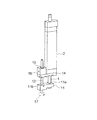
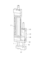
以下、添付図面に基づいて本発明の実施形態を詳細に説明する。図1は本発明の第一の実施形態におけるリニアモータアクチュエータの斜視図を示す。この実施形態のリニアモータアクチュエータは、例えば電子部品等の移動体を基板上にマウントするチップマウンタに組み込まれる。 Hereinafter, embodiments of the present invention will be described in detail with reference to the accompanying drawings. FIG. 1 is a perspective view of a linear motor actuator according to a first embodiment of the present invention. The linear motor actuator of this embodiment is incorporated in a chip mounter that mounts a moving body such as an electronic component on a substrate.
第一の軸部材であるロッド1には、複数のマグネット3(図2参照)が収容され、軸線方向にN極及びS極が交互に形成される。直方体形状のハウジング2には、ロッド1を囲む複数のコイル4(図2参照)が収容される。複数のコイル4は、U相,V相及びW相からなる三相コイルである。三相コイルに三相交流電流を流すと、ハウジング2に対してロッド1がその軸線方向に直線運動する。
The
ロッド1の先端には、ロッド1の軸線方向と直交する方向に細長く伸びる第一の連結部材11が固定される。第一の連結部材11にはロッド1の外径に合わせた第一の貫通孔11aが開けられる。第一の連結部材11の第一の貫通孔11aに通されたロッド1は、ねじ、接着、しまり嵌め等の固定手段によって第一の連結部材11に固定される。ロッド1が第一の連結部材11に固定されているので、ロッド1は第一の連結部材11に対してその軸線方向に相対的に移動することもできないし、第一の連結部材11に対してロッド1の軸線の回りを相対的に回転することもできない。
A first connecting
第二の軸部材12はロッド1と平行に配置される。第二の軸部材12はロッド1を折り返すようにロッド1の先端部からハウジング2側に向かって伸びる。第二の軸部材12は中空に形成される。第二の軸部材12の先端部には第一の連結部材11が固定される。第一の連結部材11には第二の軸部材12の外径に合わせた第二の貫通孔11bが開けられる。第一の連結部材11の第二の貫通孔11bに通された第二の軸部材12は、ねじ、接着、しまり嵌め等の固定手段によって第一の連結部材11に固定される。第一の連結部材11に固定されているので、第二の軸部材12は第一の連結部材11に対してその軸線方向に相対的に移動することもできないし、第一の連結部材11に対して第二の軸部材12の軸線の回りを相対的に回転することもできない。第一の連結部材11にはロッド1の先端部及び第二の軸部材12の先端部が固定されるので、ハウジング2に対してロッド1が軸線方向に直線運動するのに連れて、第二の軸部材12がその軸線方向に直線運動する。
The
ハウジング2の端面には、ロッド1の軸線と直交する方向で第二の軸部材12に向かって細長く伸びる矩形プレート状の第二の連結部材14が固定される。第二の連結部材14はボルト、ねじ等の固定手段によってハウジング2の端面に固定される。ロッド1は第二の連結部材14には連結されていない。第二の連結部材14にはロッド1の外径よりも大きな孔(図示せず)が開けられる。ロッド1はこの孔に挿通される。第二の連結部材14は、第二の軸部材12の、第一の連結部材11よりもハウンジング側の部分とハウジング2とを連結する。第二の連結部材14には、外筒15が埋め込まれる直方体形状のケーシング16が取り付けられる。ケーシング16はボルト、ねじ等の固定手段によって第二の連結部材14に固定される。第二の連結部材14に一体に固定される外筒15は、第二の軸部材12が直線運動するのを案内する。もし第二の連結部材14を設けないと、ロッド1の軸線の回りを第二の軸部材12が旋回してしまう。第二の連結部材14は、ロッド1の軸線の回りを第二の軸部材12が旋回するのを防止する。第二の軸部材12及び外筒15の構造については後述する。
A rectangular plate-like second connecting
第二の軸部材12の先端部には、電子部品等を吸着する吸着具として吸着パッド17が取り付けられる。第二の軸部材12には、ホースを介して図示しない真空発生装置が接続される。真空発生装置を作動させると、ホースや第二の軸部材12を介して吸着パッド17からエアーが吸引される。
A
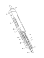
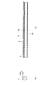
図2は、リニアモータの斜視図を示す。リニアモータは、N極及びS極が軸線方向に交互に形成されるように複数のマグネット3を有するロッド1と、ロッド1を囲み、ロッド1の軸線方向に積層される複数のコイル4と、複数のコイル4が収容されるハウジング2と、を備える。リニアモータは、マグネット3に発生する磁界と複数のコイル4に流す電流によって運動するための推力を発生する。
FIG. 2 shows a perspective view of the linear motor. The linear motor includes a
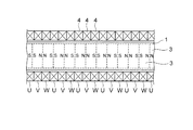
図3はリニアモータの概念図を示す。ロッド1内の中空空間には、円盤状の複数のマグネット3が互いに同極が対向するように、すなわちN極とN極が、S極とS極とが対向するように積層される。ロッド1の周囲には、ロッド1を囲む複数のコイル4が積層される。コイル4は3つでU・V・W相からなる一組の三相コイルとなる。三相コイルを複数組み合わせてコイルユニットが構成される。三相コイルに120°ずつ位相が異なる三相交流電流を流すと、コイル4の軸線方向に移動する移動磁界が発生する。ロッド1は移動磁界により推力を得て、移動磁界の速さと同一の速さでコイル4に対して相対的に直線運動を行なう。
FIG. 3 shows a conceptual diagram of a linear motor. A plurality of disk-shaped
図2に示されるように、リニアモータのロッド1は、ハウジング2にロッド1の軸線方向に移動可能に支持される。コイルユニットはコイルホルダ5に保持され、これらコイルユニット及びコイルホルダ5はハウジング2に収容される。
As shown in FIG. 2, the
ロッド1は、例えばステンレス等の非磁性材からなり、中空空間を有する。ロッド1の中空空間には、円柱状の複数のマグネット3が互いに同極が対向するように積層される。マグネット3の間には、例えば鉄等の磁性体からなるポールシュー7が介在される。
The
コイル4は銅線を螺旋状に巻いたもので、コイルホルダ5に保持されている。この実施形態では、コイル4及びコイルホルダ5を射出成型の金型にセットし、溶融した樹脂又は特殊セラミックスを金型内に流すインサート成形によってハウジング2を形成する。成形品を金型から取り出すと、コイル4の周囲がハウジング2で覆われている状態になる。インサート成形によってハウジング2を形成することで、ハウジング2の肉厚を薄くできるという利点がある。リニアモータを並べて使用する場合には、リニアモータの寸法を小さくする必要がある。
The
ハウジング2には、リニアモータをチップマウンタのヘッドに取り付けるための取付け部としてねじ孔2bが加工される。またハウジング2には、ヘッドに対するハウジング2の位置決めをするためのピンが挿入される位置決め穴2cが開けられる。コイル4との絶縁を保つ必要があるため、ハウジング2の材料には絶縁性の高い樹脂が使用される。ハウジング2には、放熱性を高めるためにフィン2aが形成される。
A
ロッド1はリニアモータの作動中、コイル4内で浮いている状態になっている。ロッド1の直線運動を支えるために、ロッド1の軸線方向におけるハウジング2の両端部には、ブッシュ8が設けられる。ブッシュ8は、ハウジング2の両端に一体に成形されたエンド部材9に固定される。
The
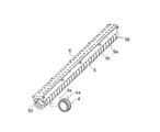
図4は、コイルホルダ5に保持されたコイルユニットを示す。コイルユニットは、銅線を螺旋状に巻いた複数のコイル4を軸線方向に積層したものである。コイル4のリード線4aは一本一本接続する必要がある。コイル4のリード線4aの配線を簡素化するために絶縁基板6が用意される。
FIG. 4 shows the coil unit held by the
図5は、コイル4、及びコイル4を保持するコイルホルダ5の詳細図を示す。隣接するコイル4同士を絶縁する必要があるので、コイル4間には絶縁材として樹脂製のスペーサ部5bが介在される。スペーサ部5bはコイル4の正面形状と同様に円環形状に形成される。スペーサ部5bはコイル4の配列方向に細長く伸びる板状のホルダ本体部5aに一体に成形される。コイルホルダ5は樹脂の射出成形品であり、コイル4の配列方向に細長く伸びる板状のホルダ本体部5aと、ホルダ本体部5aから垂下する薄肉の複数のスペーサ部5bとから構成される。ホルダ本体部5aの上面には、絶縁基板6の取り付け座が形成される。ホルダ本体部5aの側面には、射出成形するときにコイルホルダ5を金型に固定するための突起5c(図4参照)が設けられる。射出成形時の圧力により、コイルホルダ5が位置ずれするのを防止するためである。図4に示されるように、ホルダ本体部5aの下面には、コイル4の外形形状に合わせた曲面状の窪み5dが形成される。リード線4aを絶縁基板6のスルーホール6a(図4にはスルーホール6aにコイル4の配線4aが半田付けされた状態が示されている)まで導くために、ホルダ本体部5aには絶縁基板6のスルーホール6aと同じ位置に複数の配線用孔が空けられる。
FIG. 5 shows a detailed view of the
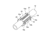
図6は、第二の連結部材14に一体に固定される外筒15を示す。円筒形の外筒15の内部には、保持器21とボール18が組み込まれる。外筒15の内部には、第二の軸部材12がその軸線方向に直線運動可能に組み込まれる。第二の軸部材12の外径の断面は円形に形成される。ボール18と第二の軸部材12とは点接触するので、最小の摩擦抵抗で第二の軸部材12が直線運動する。
FIG. 6 shows the
第二の軸部材12は中空丸棒からなる。第二の軸部材12の外周面を直接ボール18が転動するので、第二の軸部材12は硬さ、表面粗さ、及び寸法精度に注意して製作される。第二の軸部材12の材質には、好ましくは軸受け鋼、炭素工具鋼等の焼入れに適した材質が用いられ、第二の軸部材12の表面は焼入れ等の熱処理を経て所定の硬度に加工される。第二の軸部材12の表面粗さを低減するために、第二の軸部材12の外周面は研削加工されてもよい。
The
外筒15は中空の筒体である。図6に示されるように、外筒15の外周面は円筒形状であり、内周面は異形形状である。異形形状の内径部に軸線方向に伸びる負荷ボール転走溝が形成される。負荷ボール転走溝は周方向に均等間隔を空けて例えば四条形成される。外筒15は例えば、素材を押出し成形等により加工し、内径・外径・端面等を切削加工し、焼入れ後、外径・内径を研削加工することで製造される。外筒15の材質には、好ましくは軸受け鋼、炭素工具鋼等の焼入れに適した材質が用いられる。外筒15の外周面には、外筒15を第二の連結部材14に取り付けるための止め輪が装着される外周溝15aが形成される。外筒15は完全な円筒形でなくても、軸線方向に切断された所謂開放形であってもよいし、外筒15と第二の軸部材12との隙間を調整できるように円筒形の外筒15に軸線方向に伸びるすり割りが設けられてもよい。
The
外筒15と第二の軸部材12との間に介在されるボール18は、一般の軸受けに用いられる転動体と同様に鋼製である。外筒15には保持器21が組み込まれる。保持器21は外筒15の内側に組み込まれる中空筒体である。保持器21には、四つのサーキット状ボール循環経路19が形成される。ボール循環経路19は、外筒15の負荷ボール転走溝に沿った負荷ボール転走路19a、負荷ボール転走路19aと平行に伸びるボール戻し通路19b、負荷ボール転走路19aの端とボール戻し通路19bの端とを接続する円弧形状の方向転換路19cで構成される。負荷ボール転走路19aは保持器21の外周面及び内周面の双方に開口する。負荷ボール転走路19aに配列されたボール18は、外筒15の負荷ボール転走溝及び第二の軸部材12の外周面に接触する。外筒15に対して第二の軸部材12が相対的に直線運動すると、負荷ボール転走路19aに配列されたボール18はこれらの間で転がり運動する。ボール戻し通路19bは保持器21の外周面のみに開口する。外筒15と保持器21のボール戻し通路19bとによって閉じた断面の無負荷戻し通路が構成される。無負荷戻し通路においては、ボール18の周囲には僅かな遊びがある。ボール18は後続のボール18に押されながら無負荷戻し通路を移動する。保持器21は、止め輪20によって外筒15の所定位置に固定される。
A
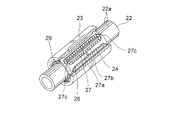
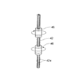
図7は、第二の軸部材及び外筒の他の例を示す。この例の第二の軸部材22の外周面には、スプライン溝として長手方向に伸びる複数条のボール転走溝22aが形成される。スプライン外筒23の内周面には第二の軸部材22の複数条のボール転走溝22aに対向する複数条の負荷ボール転走溝が形成される。第二の軸部材22は第一の連結部材11に固定されているので、第二の軸部材22は第一の連結部材11によって回り止めされている。このため、スプライン外筒23に対して第二の軸部材22を回り止めする必要はない。しかし、第二の軸部材22の外周面にボール転走溝22aを形成することによって、例えば第二の軸部材22の先端の吸着パッド17に第二の軸部材22の軸線に直交する方向の荷重がかかったり、軸線回りのモーメント荷重がかかったりする場合でも、これらの荷重を負荷できるようになる。さらに、第二の軸部材22の案内の精度を上げたり、ボール24の寿命を長くしたりすることもできる。
FIG. 7 shows another example of the second shaft member and the outer cylinder. A plurality of
第二の軸部材22は中空丸棒からなる。第二の軸部材22の外周面には、軸線方向に伸びる複数条(この実施形態では六条)のボール転走溝22aが形成される。ボール転走溝22aの断面形状はボール24の曲率よりも若干大きいサーキュラーアーク溝形状に形成される。ボール24が負荷を受けながら転がり運動するので、第二の軸部材22のボール転走溝22aの硬さ、表面粗さ、及び寸法精度は注意して製作される。第二の軸部材22の材質には、好ましくは軸受け鋼、炭素工具鋼などの焼入れに適した材質が用いられる。また、第二の軸部材22のボール転走溝22aの表面は焼入れなどの熱処理を経て所定の硬度に加工される。ボール転走溝22aの表面粗さを低減するために、ボール転走溝22aの外周面は研削加工される。
The
スプライン外筒23と第二の軸部材22との間に介在されるボール24は、一般の軸受けに用いられる転動体と同様に鋼製である。スプライン外筒23は中空の筒体である。スプライン外筒23の外周面は円筒形状であり、スプライン外筒23の内周面は大径部と小径部とを繰り返して有する異形形状である。内径部にボール転走溝22aに対向し、軸線方向に伸びる負荷ボール転走溝が形成される。スプライン外筒23は例えば、素材を押出し成形などにより異形形状に加工し、内径・外径・端面などを切削加工し、焼入れ後、外径・内径を研削加工することで製造される。スプライン外筒23の材質には、好ましくは軸受け鋼、炭素工具鋼などの焼入れに適した材質が用いられる。
The
図7に示されるように、スプライン外筒23には保持器26が組み込まれる。保持器26はスプライン外筒23の内側に組み込まれる中空筒体である。保持器26の外周面は、スプライン外筒23の内周面に形状を合わせた異形形状であり、大径部と小径部とを有する。保持器26には、スプライン外筒23の負荷ボール転走溝の条数に合わせて複数のサーキット状のボール循環経路27が形成される。ボール循環経路27は、スプライン外筒23の負荷ボール転走溝に沿った負荷ボール転走路27a、負荷ボール転走路27aと平行に伸びるボール戻し通路27b、負荷ボール転走路27aの端とボール戻し通路27bの端とを接続する円弧形状の方向転換路27cで構成される。負荷ボール転走路27aは保持器26の小径部にあり、保持器26の外周面及び内周面の双方に開口する。ボール24はスプライン外筒23の負荷ボール転走溝と第二の軸部材22のボール転走溝22aに接触しながら転がり運動する。ボール戻し通路27bは保持器26の大径部にあり、保持器26の外周面のみに開口する。スプライン外筒23と保持器26のボール戻し通路27bとによって閉じた断面の無負荷戻し通路が構成される。無負荷戻し通路においては、ボール24の周囲には僅かな遊びがある。ボール24は後続のボール24に押されながら無負荷戻し通路を移動する。保持器26は、ボール循環経路27に配列・収容されたボール列を循環可能に保持し、スプライン外筒23を第二の軸部材22から外したときにボール24が脱落するのを防止する。この保持器26は、止め輪29によってスプライン外筒23の所定位置に固定される。
As shown in FIG. 7, a
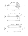
図8は、本発明例と比較例とで、リニアモータアクチュエータの全体の長さ及び推力を比較したものである。図8中(A)及び(B)が比較例を示し、(C)が本発明例を示す。図8(C)に示されるように、本発明例においては、第一の軸部材であるロッド1に並列にかつロッド1を折り返すように第二の軸部材12が配置されるので、推力を落とすことなく、リニアモータアクチュエータの全長を短くすることができる。これに対し、図8(A)及び(B)に示されるように、ロッド1に直列にスプライン軸31を直結し、スプラインナット32によってスプライン軸31の直線運動を案内した場合、スプライン軸31がストロークする範囲であるシャフト移動範囲(図参照)のコイル4は有効に働かなくなる。スプライン軸31の内部にマグネット3を収容することができないからである。このため、図8(A)に示されるように、本発明例のように有効コイル数を5setにする場合、すなわち本発明例に推力を合わせた場合、リニアモータアクチュエータの全体の長さが138mmから164mmに増加してしまう。一方、図8(B)に示されるように、本発明例にリニアモータアクチュエータの全長を合わせた場合、有効コイル数が3setになってしまい、推力が低下してしまうのがわかる。
FIG. 8 compares the entire length and thrust of the linear motor actuator in the present invention example and the comparative example. 8A and 8B show comparative examples, and FIG. 8C shows an example of the present invention. As shown in FIG. 8C, in the example of the present invention, the
ロッドタイプのリニアモータにおいては、ロッド1がコイル4内で浮いている状態にあるので、ロッド1がその軸線の回りを回転してしまう。ロッド1を第一の連結部材11に固定することで、ロッド1の軸線回りの回転を防止することができる。さらに第二の軸部材12を第一の連結部材11に固定することで、第二の軸部材12のその軸線の回りの回転を防止することができ、第二の軸部材12の先端に設けられる吸着パッド17(図1参照)の姿勢を一定に保つことができる。
In the rod type linear motor, since the
さらに第二の軸部材12を中空に形成することで、第二の軸部材12を吸着パッドの真空系統として有効に利用することができる。ロッド1のマグネット3に真空系統としての貫通孔を開けなくて済むので、真空系統を容易に構成することができ、また、真空系統の長さ(第二の軸部材12の軸線方向の長さ)を短くすることができるので、エアーの応答性も向上させることができる。第二の軸部材12の軸線方向の長さが短いので、第二の軸部材12に接続される真空系統のホースの取扱いも容易になる。
Furthermore, by forming the
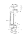
図9は、本発明の第二の実施形態におけるリニアモータアクチュエータの斜視図を示す。この実施形態のリニアモータアクチュエータにおいても、リニアモータの第一の軸部材であるロッド1と平行に第二の軸部材42が設けられる。ロッド1の先端部と第二の軸部材42の先端部とは第一の連結部材41に固定されている。リニアモータのハウジング2の端部には、第一の連結部材41と平行な第二の連結部材44が固定される。第二の連結部材44は、第二の軸部材42が直線運動するのを許容しつつ、第二の軸部材42がロッド1の回りを旋回するのを防止する。互いに平行なロッド1及び第二の軸部材42、並びに互いに平行な第一及び第二の連結部材41,44によって井桁形状が形成される。
FIG. 9 shows a perspective view of the linear motor actuator in the second embodiment of the present invention. Also in the linear motor actuator of this embodiment, the
この実施形態のリニアモータアクチュエータにおいて、第二の軸部材42は、第二の軸部材42の軸線方向に離間して配列された二つの外筒46によって案内される。第二の連結部材42には、第二の軸部材42の軸線方向に細長い立方体形状のケーシング46が取り付けられる。二つの外筒46はこのケーシング45に収容される。外筒46には、図6に示すボールブッシュタイプが用いられるか、又は図7に示すボールスプラインタイプが用いられる。なお、リニアモータがロッドタイプリニアモータである点、第二の軸部材42が中空であり、先端に吸着パッドが設けられる点は、上記第一の実施形態のリニアモータアクチュエータと同一である。
In the linear motor actuator of this embodiment, the
第二の実施形態のリニアモータアクチュエータによれば、第二の軸部材42が直線運動するのを軸線方向に離間させた二つの外筒46で案内するので、第二の軸部材42が、第二の軸部材42の先端にかかるモーメント荷重によって振れたり、傾いたりするのを防止することができる。
According to the linear motor actuator of the second embodiment, the
図10は、上記第二の実施形態のリニアモータアクチュエータにおいて、第二の軸部材42の剛性をさらに高めた例を示す。この例において、第二の軸部材42及び二つの外筒46には、図7に示すボールスプラインタイプが用いられる。第二の軸部材42の外周面には、軸線方向に伸びる複数本のスプライン溝42a(図7の22aに相当)が形成される。二つの外筒46の内周面には、第二の軸部材42の複数本のスプライン溝に対向する転動体転走溝としてのボール転走溝が形成される。外筒46にはさらに、第二の軸部材42のスプライン溝42と外筒46のボール転走溝とを転がるボール(図7の24に相当)を循環させるボール循環経路(図7の27に相当)が設けられる。二つの外筒46は、第二の軸部材42に対して互いに反対方向にねじられた状態でケーシングに取り付けられている。すなわち、上側の外筒46は第二の軸部材に対して時計方向のトルクを与えられた状態で、下側の外筒46は反時計方向のトルクを与えられた状態でケーシング45に固定される。このため、二つの外筒46のボール転走溝の位相は周方向に僅かにずれている。
FIG. 10 shows an example in which the rigidity of the
この例のリニアモータアクチュエータによれば、上下二つの外筒46に収容されるボールが周方向に互いに反対方向に圧縮されるので、予圧が付与された状態を保つことができる。このため、第二の軸部材42の周方向のがたつきをなくすことができ、第二の軸部材42の周方向の剛性を向上させることができる。
According to the linear motor actuator of this example, since the balls accommodated in the upper and lower
図11は、本発明の第三の実施形態におけるリニアモータアクチュエータを示す。この実施形態においては、リニアモータのロッド1の回転を阻止する回転阻止構造46A,46Bがロッド1の軸線方向の両端部に配置されている。すなわち、回転阻止構造46A,46Bは、ロッド1の軸線方向の一方の端部に配置される第一の回転阻止構造46Aと、ロッド1の軸線方向の他方の端部に配置される第二の回転阻止構造46Bと、から構成される。回転阻止構造46A,46Bそれぞれは、ロッド1と平行な第二の軸部材12と、ロッド1の先端部と第二の軸部材12の先端部に固定される第一の連結部材11と、ハウジング2の端部に固定され、第二の軸部材12がその軸線方向に運動するのを許容する第二の連結部材14と、から構成される。第二の連結部材14には、ケーシング16が取り付けられ、ケーシングには、第二の軸部材12が直線運動するのを案内する外筒15が収容される。
FIG. 11 shows a linear motor actuator in the third embodiment of the present invention. In this embodiment, rotation blocking structures 46A and 46B that block the rotation of the
この第三の実施形態のリニアモータアクチュエータによれば、ロッド1の軸線方向の両端部でロッド1の回転が阻止されているので、ロッド1の剛性を高めることができ、ひいてはロッド1に連結される第二の軸部材12の剛性を高めることができる。
According to the linear motor actuator of the third embodiment, since the rotation of the
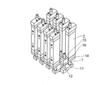
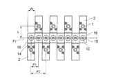
図12及び図13は、本発明のリニアモータアクチュエータを複数組み合わせた多軸リニアモータアクチュエータを示す。この多軸リニアモータアクチュエータにおいては、複数のリニアモータのロッド1を一列に積層するのではなく、リニアモータのロッド1と平行な第二の軸部材12を一列に積層している。複数の第二の軸部材12はその軸線が平行になるようにかつその軸線が一平面F1(図13参照)内に配置されるように積層される。外筒15が収容されるケーシング16は直方体形状に形成される。ハウジング2とケーシング16を連結する第二の連結部材14の積層方向における横幅Wは、ケーシング16の横幅に等しく、またハウジング2の横幅に等しい。複数のケーシング16はその側面が互いに接触する。
12 and 13 show a multi-axis linear motor actuator in which a plurality of linear motor actuators of the present invention are combined. In this multi-axis linear motor actuator, the
隣り合う一対のリニアモータアクチュエータの一対のロッド1は、第二の軸部材12の軸線が含まれる一平面F1を挟んで当該一平面F1の両側に配置される。一対のロッド1それぞれは一平面F1に直交する方向にそれぞれ平面F1から一定の距離Lを開けて配置される。隣り合う一対のリニアモータアクチュエータの一対のロッド1は、一平面F1を挟んで一平面F1の両側に互い違いに配列されるので、一平面F1の片側に配列されるロッド1間のピッチP2は第二の軸部材12間のピッチP1の二倍になる。
A pair of
マグネット3を有するロッド1間の距離が短いと、一つのロッド1が軸線方向に移動するのに連れて隣のロッド1が移動方向に移動する。隣り合う一対のロッド1のマグネット3同士の磁力の影響が生ずるからである。これを防止するためには、ロッド1間に磁気干渉を防ぐ磁気シールドプレートが必要になる。本実施形態によれば、一平面F1の片側に配列されるロッド1間には十分な距離が保たれるので、磁気干渉を防ぐ磁気シールドプレートが不要になる。
When the distance between the
なお、本発明は上記実施形態に限られることなく、本発明の要旨を変更しない範囲で種々変更できる。例えば、第二の軸部材の先端に取り付けられる工具の回転姿勢を制御できるように第二の軸部材を回転させる機構やモータを設けてもよい。第二の軸部材は中空に限られることはなく、アクチュエータの用途に応じて中実に形成されてもよい。 In addition, this invention is not limited to the said embodiment, In the range which does not change the summary of this invention, it can change variously. For example, you may provide the mechanism and motor which rotate a 2nd shaft member so that the rotation attitude | position of the tool attached to the front-end | tip of a 2nd shaft member can be controlled. The second shaft member is not limited to being hollow, and may be formed solid according to the application of the actuator.
また、推力を大きくするために、ロッドがストロークする全範囲においてコイルに対向するマグネットが設けられることが望ましいが、アクチュエータに要求される推力が大きくない場合には、ロッドがストロークする全範囲においてコイルに対向するマグネットが設けられなくてもよい。すなわち、ロッドに収容されるマグネットの領域が少なくてもよい。 In order to increase the thrust, it is desirable to provide a magnet facing the coil in the entire range where the rod strokes. However, if the thrust required for the actuator is not large, the coil is applied in the entire range where the rod strokes. There may be no need to provide a magnet facing the. That is, the area of the magnet accommodated in the rod may be small.
複数のリニアモータアクチュエータが並べられる多軸リニアモータアクチュエータにおいて、平行に並べられる第二の軸部材及びロッドは一平面内に配列されなくても、一平面からずれて例えばジグザグ状に配列されてもよい。全ての隣り合う一対のロッドが第二の軸部材の軸線が含まれる平面の両側に配置されなくても、少なくとも一対のロッドが第二の軸部材の軸線が含まれる平面の両側に配置されればよい。 In a multi-axis linear motor actuator in which a plurality of linear motor actuators are arranged, the second shaft members and the rods arranged in parallel may be arranged in a zigzag pattern, for example, without being arranged in one plane or shifted from one plane. Good. Even if all adjacent pairs of rods are not disposed on both sides of the plane including the axis of the second shaft member, at least a pair of rods are disposed on both sides of the plane including the axis of the second shaft member. That's fine.
多軸リニアモータアクチュエータにおいて、ハウジング間に磁気シールドプレートを介在させることができれば、リニアモータのロッドが第二の軸部材が含まれる平面の片側に隣り合うように配列されてもよい。また、リニアモータのロッドの軸線を平行に且つ一列に配置し、第二の軸部材をロッドの軸線が含まれる平面を挟んで当該平面の両側に配置してもよい。 In the multi-axis linear motor actuator, if the magnetic shield plate can be interposed between the housings, the rods of the linear motor may be arranged so as to be adjacent to one side of the plane including the second shaft member. Further, the axis of the rod of the linear motor may be arranged in parallel and in a line, and the second shaft member may be arranged on both sides of the plane across the plane including the axis of the rod.
第二の連結部材はエンド部材を含むハウジングに一体に成形されてもよい。外筒と第二の軸部材との間にはボールが介在されなくてもよく、ブッシュからなる外筒に対して第二の軸部材が滑ってもよい。 The second connecting member may be integrally formed with the housing including the end member. A ball may not be interposed between the outer cylinder and the second shaft member, and the second shaft member may slide with respect to the outer cylinder made of the bush.
さらに、第二の軸部材の先端には吸着パッド以外に電気的な治具を取り付けてもよい。この場合、第二の軸部材の中空空間を配線スペースとして利用することができる。 Furthermore, an electric jig other than the suction pad may be attached to the tip of the second shaft member. In this case, the hollow space of the second shaft member can be used as a wiring space.
1…ロッド(第一の軸部材),2…ハウジング,3…マグネット,4…コイル,11…第一の連結部材,12…第二の軸部材,14…第二の連結部材,15…外筒,16…ケーシング,17…吸着パッド(吸着具),22…第二の軸部材,23…スプライン外筒(外筒),P1…平面
DESCRIPTION OF
Claims (9)
前記第一の軸部材を囲み、前記第一の軸部材の軸線方向に積層される複数のコイルと、
前記複数のコイルが収容されるハウジングと、
前記第一の軸部材と平行に配置される第二の軸部材と、
前記ハウンジングに対して前記第一の軸部材がその軸線方向に直線運動するのに連れて、前記第二の軸部材がその軸線方向に直線運動するように、前記第一の軸部材と前記第二の軸部材を連結する第一の連結部材と、
前記第二の軸部材がその軸線方向に直線運動できるように前記第二の軸部材と前記ハウジングとを連結すると共に、前記第一の軸部材の軸線の回りを前記第二の軸部材が旋回するのを防止する第二の連結部材と、を備えるリニアモータアクチュエータ。 A first shaft member having a plurality of magnets and having N and S poles alternately formed in the axial direction;
A plurality of coils surrounding the first shaft member and stacked in the axial direction of the first shaft member;
A housing that houses the plurality of coils;
A second shaft member disposed in parallel with the first shaft member;
The first shaft member and the first shaft member are linearly moved in the axial direction as the first shaft member linearly moves in the axial direction with respect to the housing. A first connecting member that connects the two shaft members;
The second shaft member and the housing are coupled so that the second shaft member can linearly move in the axial direction thereof, and the second shaft member rotates around the axis of the first shaft member. And a second connecting member for preventing the linear motor actuator.
前記少なくとも二つの外筒それぞれには、前記複数本のスプライン溝に対向する複数の転動体転走溝が形成されると共に、前記複数のスプライン溝と前記複数の転動体転走溝との間を転がる転動体を循環させる複数の転動体循環経路が設けられ、
前記少なくとも二つの外筒が前記第二の軸部材に対して反対方向にねじられた状態で前記ケーシングに収容されることを特徴とする請求項6に記載のリニアモータアクチュエータ。 A plurality of spline grooves extending in the axial direction of the second shaft member are formed on the outer peripheral surface of the second shaft member,
Each of the at least two outer cylinders is formed with a plurality of rolling element rolling grooves facing the plurality of spline grooves, and between the plurality of spline grooves and the plurality of rolling element rolling grooves. A plurality of rolling element circulation paths for circulating the rolling elements that roll are provided,
The linear motor actuator according to claim 6, wherein the at least two outer cylinders are accommodated in the casing in a state of being twisted in an opposite direction with respect to the second shaft member.
複数の第二の軸部材の軸線が平行に配置され、かつ、隣り合う一対のリニアモータアクチュエータの一対の第一の軸部材が、隣り合う一対の第二の軸部材の軸線が含まれる平面を挟んで当該平面の両側に配置されることを特徴とする多軸リニアモータアクチュエータ。 A multi-axis linear motor actuator in which a plurality of linear motor actuators according to any one of claims 1 to 8 are combined,
A plurality of second shaft members are arranged in parallel, and a pair of first shaft members of a pair of adjacent linear motor actuators includes a plane including an axis of a pair of adjacent second shaft members. A multi-axis linear motor actuator characterized in that it is arranged on both sides of the plane with a sandwich.
Priority Applications (1)
| Application Number | Priority Date | Filing Date | Title |
|---|---|---|---|
| JP2009178165A JP5542384B2 (en) | 2008-07-30 | 2009-07-30 | Linear motor actuator and multi-axis linear motor actuator |
Applications Claiming Priority (3)
| Application Number | Priority Date | Filing Date | Title |
|---|---|---|---|
| JP2008195761 | 2008-07-30 | ||
| JP2008195761 | 2008-07-30 | ||
| JP2009178165A JP5542384B2 (en) | 2008-07-30 | 2009-07-30 | Linear motor actuator and multi-axis linear motor actuator |
Related Child Applications (1)
| Application Number | Title | Priority Date | Filing Date |
|---|---|---|---|
| JP2013223411A Division JP5552566B2 (en) | 2008-07-30 | 2013-10-28 | Linear motor actuator and multi-axis linear motor actuator |
Publications (2)
| Publication Number | Publication Date |
|---|---|
| JP2010057357A true JP2010057357A (en) | 2010-03-11 |
| JP5542384B2 JP5542384B2 (en) | 2014-07-09 |
Family
ID=42072678
Family Applications (2)
| Application Number | Title | Priority Date | Filing Date |
|---|---|---|---|
| JP2009178165A Active JP5542384B2 (en) | 2008-07-30 | 2009-07-30 | Linear motor actuator and multi-axis linear motor actuator |
| JP2013223411A Active JP5552566B2 (en) | 2008-07-30 | 2013-10-28 | Linear motor actuator and multi-axis linear motor actuator |
Family Applications After (1)
| Application Number | Title | Priority Date | Filing Date |
|---|---|---|---|
| JP2013223411A Active JP5552566B2 (en) | 2008-07-30 | 2013-10-28 | Linear motor actuator and multi-axis linear motor actuator |
Country Status (1)
| Country | Link |
|---|---|
| JP (2) | JP5542384B2 (en) |
Cited By (7)
| Publication number | Priority date | Publication date | Assignee | Title |
|---|---|---|---|---|
| EP2403118A2 (en) | 2010-07-01 | 2012-01-04 | Kabushiki Kaisha Yaskawa Denki | Actuator |
| JP2012075287A (en) * | 2010-09-29 | 2012-04-12 | Thk Co Ltd | Linear motor actuator |
| CN104124853A (en) * | 2013-04-25 | 2014-10-29 | 山洋电气株式会社 | Shaft rotary type linear motor and shaft rotary type linear motor unit |
| CN104467268A (en) * | 2013-09-24 | 2015-03-25 | 山洋电气株式会社 | Linear motor unit |
| WO2015046033A1 (en) * | 2013-09-25 | 2015-04-02 | Thk株式会社 | Linear motor actuator with ball spline and method for manufacturing same |
| CN109391118A (en) * | 2017-08-07 | 2019-02-26 | 山洋电气株式会社 | Axis rotates linear motor |
| JP7503833B2 (en) | 2020-09-11 | 2024-06-21 | 日本パルスモーター株式会社 | Multi-axis linear motor actuator |
Families Citing this family (5)
| Publication number | Priority date | Publication date | Assignee | Title |
|---|---|---|---|---|
| JP6872475B2 (en) * | 2017-12-26 | 2021-05-19 | ミネベアミツミ株式会社 | Multi-axis actuator with integrated load sensor and load sensor |
| JP6543687B1 (en) * | 2017-12-26 | 2019-07-10 | ミネベアミツミ株式会社 | Load sensor and load sensor integrated multi-axis actuator |
| JP6543686B1 (en) | 2017-12-26 | 2019-07-10 | ミネベアミツミ株式会社 | Load sensor and load sensor integrated multi-axis actuator |
| TWI660133B (en) | 2018-06-22 | 2019-05-21 | 和碩聯合科技股份有限公司 | Telescopic adjuster |
| JP2020065426A (en) * | 2018-10-19 | 2020-04-23 | Thk株式会社 | Actuator unit and actuator |
Citations (2)
| Publication number | Priority date | Publication date | Assignee | Title |
|---|---|---|---|---|
| JP2000092813A (en) * | 1998-09-11 | 2000-03-31 | Minolta Co Ltd | Linear motor driving device |
| JP2002307360A (en) * | 2001-04-13 | 2002-10-23 | Juki Corp | Mounting head of electronic part mounting device |
-
2009
- 2009-07-30 JP JP2009178165A patent/JP5542384B2/en active Active
-
2013
- 2013-10-28 JP JP2013223411A patent/JP5552566B2/en active Active
Patent Citations (2)
| Publication number | Priority date | Publication date | Assignee | Title |
|---|---|---|---|---|
| JP2000092813A (en) * | 1998-09-11 | 2000-03-31 | Minolta Co Ltd | Linear motor driving device |
| JP2002307360A (en) * | 2001-04-13 | 2002-10-23 | Juki Corp | Mounting head of electronic part mounting device |
Cited By (22)
| Publication number | Priority date | Publication date | Assignee | Title |
|---|---|---|---|---|
| EP2403118A3 (en) * | 2010-07-01 | 2014-10-29 | Kabushiki Kaisha Yaskawa Denki | Actuator |
| KR101475555B1 (en) * | 2010-07-01 | 2014-12-31 | 가부시키가이샤 야스카와덴키 | Actuator |
| EP2403118A2 (en) | 2010-07-01 | 2012-01-04 | Kabushiki Kaisha Yaskawa Denki | Actuator |
| JP2012075287A (en) * | 2010-09-29 | 2012-04-12 | Thk Co Ltd | Linear motor actuator |
| US9712030B2 (en) | 2013-04-25 | 2017-07-18 | Sanyo Denki Co., Ltd. | Shaft rotary type linear motor and shaft rotary type linear motor unit |
| CN104124853A (en) * | 2013-04-25 | 2014-10-29 | 山洋电气株式会社 | Shaft rotary type linear motor and shaft rotary type linear motor unit |
| DE102014105677A1 (en) | 2013-04-25 | 2014-10-30 | Sanyo Denki Co., Ltd. | Rotary shaft-type linear drive motor and rotary shaft-like linear drive motor unit |
| KR20140127764A (en) | 2013-04-25 | 2014-11-04 | 산요 덴키 가부시키가이샤 | Shaft rotating type linear motor and shaft rotating type linear motor unit |
| TWI618338B (en) * | 2013-04-25 | 2018-03-11 | 山洋電氣股份有限公司 | Shaft rotary type linear motor and shaft rotary type linear motor unit |
| US9853530B2 (en) | 2013-09-24 | 2017-12-26 | Sanyo Denki Co., Ltd. | Linear motor unit |
| DE102014112022A1 (en) | 2013-09-24 | 2015-03-26 | Sanyo Denki Co., Ltd. | Linear motor unit |
| CN104467268A (en) * | 2013-09-24 | 2015-03-25 | 山洋电气株式会社 | Linear motor unit |
| CN104467268B (en) * | 2013-09-24 | 2018-10-02 | 山洋电气株式会社 | Linear motor unit |
| TWI657645B (en) * | 2013-09-24 | 2019-04-21 | 山洋電氣股份有限公司 | Linear motor unit |
| JP2015065757A (en) * | 2013-09-25 | 2015-04-09 | Thk株式会社 | Linear motor actuator with ball spline and method for manufacturing the same |
| KR20160039294A (en) | 2013-09-25 | 2016-04-08 | 티에치케이 가부시끼가이샤 | Linear motor actuator with ball spline and method for manufacturing same |
| CN105594109A (en) * | 2013-09-25 | 2016-05-18 | Thk株式会社 | Linear motor actuator with ball spline and method for manufacturing same |
| KR101666340B1 (en) * | 2013-09-25 | 2016-10-13 | 티에치케이 가부시끼가이샤 | Linear motor actuator with ball spline and method for manufacturing same |
| WO2015046033A1 (en) * | 2013-09-25 | 2015-04-02 | Thk株式会社 | Linear motor actuator with ball spline and method for manufacturing same |
| CN109391118A (en) * | 2017-08-07 | 2019-02-26 | 山洋电气株式会社 | Axis rotates linear motor |
| TWI791565B (en) * | 2017-08-07 | 2023-02-11 | 日商山洋電氣股份有限公司 | Shaft Rotation Linear Motor |
| JP7503833B2 (en) | 2020-09-11 | 2024-06-21 | 日本パルスモーター株式会社 | Multi-axis linear motor actuator |
Also Published As
| Publication number | Publication date |
|---|---|
| JP5542384B2 (en) | 2014-07-09 |
| JP5552566B2 (en) | 2014-07-16 |
| JP2014018072A (en) | 2014-01-30 |
Similar Documents
| Publication | Publication Date | Title |
|---|---|---|
| JP5552566B2 (en) | Linear motor actuator and multi-axis linear motor actuator | |
| JP4860623B2 (en) | Micro actuator | |
| US8143750B2 (en) | Linear motor having coils surrounding an axially moving magnetic rod | |
| KR101279247B1 (en) | Linear motor and method of manufacturing the same | |
| JP4176075B2 (en) | Magnetic bearing spindle | |
| JP5620503B2 (en) | Electric stage | |
| JP6082646B2 (en) | Shaft rotation type linear motor and shaft rotation type linear motor unit | |
| JP6026981B2 (en) | Linear motor unit | |
| JP2011155827A (en) | Linear and rotary compound actuator system | |
| US20180166948A1 (en) | Stator core, stepper motor and linear actuator | |
| US20130213163A1 (en) | Linear actuator | |
| JP2019536415A (en) | Gear motor for air circulation valve in particular | |
| JP2000004575A (en) | Linear drive actuator | |
| US6798087B1 (en) | Rotary-linear actuator system, method of manufacturing and method of using a rotary-linear actuator | |
| WO2011033499A1 (en) | Transverse flux electrical motor | |
| KR101460400B1 (en) | Linear motor | |
| KR102414864B1 (en) | Electric motor and its manufacturing method | |
| JP4580847B2 (en) | Linear motor unit and its combination method | |
| EP1748537B1 (en) | Z-theta table activated by two rotary motors | |
| JP4734946B2 (en) | Actuator | |
| JP5097989B2 (en) | Spiral motor and method for manufacturing spiral motor | |
| US20010026101A1 (en) | Variable reluctance motor | |
| JP2006280124A (en) | Linear motor actuator | |
| WO2008100224A1 (en) | Improved linear-rotary servo actuator | |
| WO2019142116A1 (en) | Electric machine magnet insertion |
Legal Events
| Date | Code | Title | Description |
|---|---|---|---|
| A621 | Written request for application examination |
Free format text: JAPANESE INTERMEDIATE CODE: A621 Effective date: 20120606 |
|
| A131 | Notification of reasons for refusal |
Free format text: JAPANESE INTERMEDIATE CODE: A131 Effective date: 20130827 |
|
| A977 | Report on retrieval |
Free format text: JAPANESE INTERMEDIATE CODE: A971007 Effective date: 20130830 |
|
| A521 | Request for written amendment filed |
Free format text: JAPANESE INTERMEDIATE CODE: A523 Effective date: 20131028 |
|
| A131 | Notification of reasons for refusal |
Free format text: JAPANESE INTERMEDIATE CODE: A131 Effective date: 20140128 |
|
| A521 | Request for written amendment filed |
Free format text: JAPANESE INTERMEDIATE CODE: A523 Effective date: 20140326 |
|
| TRDD | Decision of grant or rejection written | ||
| A01 | Written decision to grant a patent or to grant a registration (utility model) |
Free format text: JAPANESE INTERMEDIATE CODE: A01 Effective date: 20140415 |
|
| A61 | First payment of annual fees (during grant procedure) |
Free format text: JAPANESE INTERMEDIATE CODE: A61 Effective date: 20140507 |
|
| R150 | Certificate of patent or registration of utility model |
Ref document number: 5542384 Country of ref document: JP Free format text: JAPANESE INTERMEDIATE CODE: R150 |
|
| R250 | Receipt of annual fees |
Free format text: JAPANESE INTERMEDIATE CODE: R250 |
|
| R250 | Receipt of annual fees |
Free format text: JAPANESE INTERMEDIATE CODE: R250 |
|
| R250 | Receipt of annual fees |
Free format text: JAPANESE INTERMEDIATE CODE: R250 |
|
| R250 | Receipt of annual fees |
Free format text: JAPANESE INTERMEDIATE CODE: R250 |
|
| R250 | Receipt of annual fees |
Free format text: JAPANESE INTERMEDIATE CODE: R250 |
|
| R250 | Receipt of annual fees |
Free format text: JAPANESE INTERMEDIATE CODE: R250 |
|
| R250 | Receipt of annual fees |
Free format text: JAPANESE INTERMEDIATE CODE: R250 |
|
| R250 | Receipt of annual fees |
Free format text: JAPANESE INTERMEDIATE CODE: R250 |