JP2010057058A - Image processing apparatus, image processing method, and program - Google Patents
Image processing apparatus, image processing method, and program Download PDFInfo
- Publication number
- JP2010057058A JP2010057058A JP2008221727A JP2008221727A JP2010057058A JP 2010057058 A JP2010057058 A JP 2010057058A JP 2008221727 A JP2008221727 A JP 2008221727A JP 2008221727 A JP2008221727 A JP 2008221727A JP 2010057058 A JP2010057058 A JP 2010057058A
- Authority
- JP
- Japan
- Prior art keywords
- code
- image
- index
- information
- index code
- Prior art date
- Legal status (The legal status is an assumption and is not a legal conclusion. Google has not performed a legal analysis and makes no representation as to the accuracy of the status listed.)
- Granted
Links
Images


Abstract
Description
本発明は、画像処理技術に関し、より詳細には、符号化されたコード情報を含む画像からコード情報を、高精度かつ短時間で認識する画像処理装置、画像処理方法、およびプログラムに関する。 The present invention relates to an image processing technique, and more particularly to an image processing apparatus, an image processing method, and a program for recognizing code information from an image including encoded code information with high accuracy and in a short time.
近年、画像処理装置が処理する画像データは、画像の利用制限、検索その他画像を特徴付けるためのコード情報を含むものも知られている。これらのコード情報は、画像ファイルのヘッダ情報など適切な領域に記述することもできるし、出力後の画像上の画像認識に影響を与えない箇所に、バーコード、2次元バーコードなどのコード情報として出力させることもできる。画像処理装置は、コード情報を含んだ印刷物をスキャナなどで読取った場合、コード情報をデコードして、画像処理装置が利用するべき制御データを生成し、当該印刷物の複製、編集、画像転送など画像処理装置上で、印刷物の画像を利用する各種処理(以下、本発明における画像処理として参照する。)の制御を行う。 2. Description of the Related Art In recent years, image data processed by an image processing apparatus is also known that includes code information for characterizing images, such as image usage restrictions, searches, and the like. These code information can be described in an appropriate area such as header information of an image file, and code information such as a barcode and a two-dimensional barcode is provided at a location that does not affect image recognition on the output image. Can also be output. When a printed material including code information is read by a scanner or the like, the image processing device decodes the code information to generate control data to be used by the image processing device, and reproduces, edits, and transfers images of the printed material. Various processing (hereinafter referred to as image processing in the present invention) that uses an image of a printed matter is controlled on the processing device.
このため、印刷物からコード情報を抽出する処理が効率的に行われない場合、コード情報の取得に時間がかかり、コード情報を使用して実行される後続処理までの処理効率が低下する。また、印刷物にコード情報が付加されていても、認識精度が充分でない場合、読取り側の画像処理装置で効果的にコード情報を利用した画像処理の制御ができないという問題も発生する。 For this reason, if the process of extracting the code information from the printed material is not efficiently performed, it takes time to acquire the code information, and the processing efficiency up to the subsequent process executed using the code information is lowered. In addition, even if code information is added to the printed matter, if the recognition accuracy is not sufficient, there arises a problem that the image processing apparatus on the reading side cannot effectively control the image processing using the code information.
これまで、画像に対して各種のコード情報を追加する技術が提案されており、例えば、特開2006−211535号公報(特許文献1)、特開2005−173646号公報(特許文献2)、特開2004−303223号公報(特許文献3)を挙げることができる。特許文献1では、符号化したコード画像を処理対象ドキュメントに合成し、処理対象ドキュメント上で情報コード画像の合成位置を示す合成位置情報を符号化した位置指定コード画像を処理対象ドキュメントの所定位置に合成する画像処理装置を開示している。また、特許文献2は、入力画像を矩形ブロック単位で選択し、ブロックが所定の要件を満たしているか否かを判定し、ブロック内のコードの種類を判定するコード種類判別方法を開示している。さらに、特許文献3は、2次元的に情報を記憶した長方形のパターンを含むデジタル化された文書を複数の小領域に分割し、分割された領域に対してパターン読み取りを実行させ、複数の領域から読み出した複数の情報を同時に出力する画像認識装置を開示している。
特許文献1では、所定情報コード画像を探し出すために、同一の位置指定コードを複数の所定位置に配置する。また、複数位置に配置された異なる位置指定コードを使用して所定情報コード画像を探し出す技術を開示している。特許文献1では、所定情報コード画像の位置が指定されるのみであり、複数のコード情報が存在する場合について対応できるものではない。また、位置指定コードを複数読み込ませる場合、位置指定コードのみでは、2次元的な広がりを有するコード画像の範囲を取得することができず、指定されたコード画像が存在する可能性のある領域全体をトライアンドエラー的に読出し、デコードして当該コード画像が与えるコード情報がEOFを与えるまで、網羅的に処理しなければならないという問題もある。すなわち、位置指定コードは、画像データ中に埋設されたコード画像の位置を指定するために利用されるものである。しかしながら、コード画像がさらにデコード処理を伴ってコード情報を提供するフォーマットで記録されている場合、位置指定のみでは、印刷物の読取り角度、ズレなどがある場合、についても充分な精度でコード情報を提供できない場合もあるという問題点もあった。さらに特許文献1に記載の技術は、予めコンテンツとして電子文書に一般コードが存在する場合には対応できず、汎用的な電子文書作成アプリケーションによって作成された電子文書に対しては適用できないという問題点があった。
In
また、特許文献2および特許文献3では、画像を分割し、分割された領域から取得した情報を使用してコード種類およびコード情報を取得する。特許文献2および特許文献3に記載された方法は、コード種類の決定およびデコード処理によるコード情報の取得を可能とするものの、印刷画像の全体を処理してからでなければエンコード種類およびデコード処理ができない点、およびコード情報の認識は、目的の画像を構成する画像ドットからコード情報を提供するドットを識別しながら、トライアンドエラー的にドットを抽出して実行しなければならないという点で、精度、コード画像の領域識別性、コード画像の認識開始からデコード完了までの速度といった点で充分ではなかった。
Moreover, in
また、コード情報を記録する場合、画像データの認識性を低下させないように、画像データとの関係でコード情報のサイズが変動する可能性もある。この様な場合、従来の技術では、コード情報の位置を指定する点は開示するものの、コード情報が画像データ中でどの範囲に広がっているのかについては何ら開示するものではなく、高精度かつ高速のデコード処理を実行するためには、コード情報が画像データ中に占める空間的領域を指定することが必要とされていた。 In addition, when code information is recorded, the size of the code information may vary depending on the relationship with the image data so as not to deteriorate the recognizability of the image data. In such a case, the conventional technology discloses the point of specifying the position of the code information, but does not disclose what range the code information is spread in the image data, and is highly accurate and high speed. In order to execute this decoding process, it is necessary to designate a spatial area occupied by the code information in the image data.
本発明は、上記従来技術の問題点に鑑みてなされたものであり、本発明では、画像処理装置は、画像データが含むコード画像のコーディング種類、範囲情報、および回転角度を、コード画像と対として登録するコード配置情報を作成する。コード配置情報は、複数のコード画像が画像データに含まれる場合でも対応できるように、コード配置情報リストとして作成される。コード配置情報リストは、画像処理装置が設定するコーディング種類を使用してインデックスコード画像へとエンコードされる。エンコード後のインデックスコード画像は、描画データの画像描画を行う描画コマンドに対応付けられた付属データに、インデックスコード画像、位置、サイズなどが追加されて、描画データに合成され、インデックスコード付画像が生成される。インデックスコード付画像は、ページ記述言語を使用して印刷データとされ、プリンタ制御言語を使用して駆動される画像形成エンジンを介して印刷物とされる。 The present invention has been made in view of the above problems of the prior art. In the present invention, the image processing apparatus compares the coding type, range information, and rotation angle of the code image included in the image data with the code image. Create code placement information to be registered as The code arrangement information is created as a code arrangement information list so as to cope with a case where a plurality of code images are included in the image data. The code arrangement information list is encoded into an index code image using a coding type set by the image processing apparatus. The encoded index code image is added to the attached data associated with the drawing command for drawing the drawing data image, and the index code image, position, size, etc. are added to the drawing data, and the index code image is combined. Generated. The image with the index code is set as print data using a page description language, and is printed through an image forming engine driven using a printer control language.
印刷物は、スキャナなどの画像読取り装置を使用して読取られ、コード画像をデコードして生成される制御情報を使用して画像処理を制御する画像処理装置によって画像処理を制御するために利用される。画像処理装置は、インデックスコード付き画像からインデックスコードをデコードし、デコードが成功した場合に、デコード結果としてコード配置情報を作成する。作成されたコード配置情報は、画像処理装置がその制御に利用するための一般コード情報を作成するために利用される。一般コード情報は、画像処理装置が実装するアプリケーションプログラムに送られて、アプリケーションプログラムが以後の処理を制御する。 The printed material is read using an image reading device such as a scanner, and is used to control image processing by an image processing device that controls image processing using control information generated by decoding a code image. . The image processing apparatus decodes an index code from an image with an index code, and creates code arrangement information as a decoding result when the decoding is successful. The generated code arrangement information is used for generating general code information to be used for control by the image processing apparatus. The general code information is sent to an application program installed in the image processing apparatus, and the application program controls the subsequent processing.
本発明の画像処理装置は、インデックスコード付画像を生成する形態として実装することができる。また、本発明の画像処理装置は、インデックスコード付画像から、インデックスコード画像をデコードし、デコード結果を使用してアプリケーション制御データなどを提供する一般コード情報をデコードすることによって画像処理を制御する画像処理装置としても実装することができる。 The image processing apparatus of the present invention can be implemented as a form for generating an image with an index code. In addition, the image processing apparatus of the present invention decodes an index code image from an image with an index code, and controls image processing by decoding general code information that provides application control data and the like using the decoding result. It can also be implemented as a processing device.
さらに、画像処理装置は、上述したインデックスコード付画像を印刷物として出力し、同時にインデックスコード付画像をデコードして、一般コード情報を使用して画像処理を制御する画像処理装置としても実装することができる。 Further, the image processing apparatus can be implemented as an image processing apparatus that outputs the above-described image with an index code as a printed matter, simultaneously decodes the image with the index code, and controls image processing using general code information. it can.
また、上述した画像処理装置は、複写機、多機能複写機として実装できるほか、パーソナルコンピュータとしても実装することができる。 Further, the above-described image processing apparatus can be mounted as a copying machine, a multifunction copying machine, or a personal computer.
さらに本発明では、上述した画像処理装置が実行する画像処理方法およびプログラムを提供する。 Furthermore, the present invention provides an image processing method and program executed by the above-described image processing apparatus.
本発明によれば、符号化されたコード情報を高精度かつ高速にデコードすることを可能とするインデックスコード付画像を、電子ドキュメントに追加して外部出力することが可能な画像処理装置、画像処理方法、およびプログラムを提供することができる。また、本発明によれば、インデックスコード付画像を取得して高精度・高速に制御データなどを含む一般コード情報をデコードし、以後の画像処理の制御のために提供することが可能な、画像処理装置、画像処理方法、およびプログラムを提供することができる。 According to the present invention, an image processing apparatus and an image processing device capable of adding an image with an index code that enables decoding of encoded code information with high accuracy and high speed to be output to an electronic document. Methods and programs can be provided. Further, according to the present invention, it is possible to obtain an image with an index code, decode general code information including control data with high accuracy and high speed, and provide it for control of subsequent image processing. A processing apparatus, an image processing method, and a program can be provided.
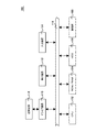
以下、本発明を実施形態をもって説明するが、本発明は後述する実施形態に限定されるものではない。図1は、本実施形態の画像処理装置の実施形態のハードウェア機能ブロックを示す。図1に示す実施形態では、画像処理装置は、パーソナルコンピュータ100として実装される。パーソナルコンピュータ100は、中央処理装置(CPU)102と、各種制御プログラムや各種データなどを記憶するROM/RAMといった固体記憶素子104とを備えており、CPU102がアプリケーションを実行するためのデータを提供するとともに、アプリケーションの実行空間を提供している。パーソナルコンピュータ100は、さらにHDD106を備えており、HDD106は、CPU102が実行する各種アプリケーションプログラムや各種データを記憶する。
Hereinafter, although this invention is demonstrated with embodiment, this invention is not limited to embodiment mentioned later. FIG. 1 shows hardware functional blocks of an embodiment of the image processing apparatus of this embodiment. In the embodiment shown in FIG. 1, the image processing apparatus is implemented as a
また、パーソナルコンピュータ100は、外部装置とのデータ通信を制御する通信部108を備えている。通信部108は、特に限定されるものではなく、例えば、USB、SCSI、IEEE1294などのバスラインを介するシリアル/パラレル通信のための通信部として構成することができる。また、通信部108は、ネットワークインタフェースカード(NIC)として参照されるネットワーク通信機能を備えていてもよい。通信部108が、ネットワーク通信機能を備えている場合、画像処理装置は、イーサネット(登録商標)などを介してインターネットまたはローカルエリアネットワーク(LAN)などを介して外部装置と通信することができる。
The
また、パーソナルコンピュータ100は、ワイアドまたはワイアレスなどの適切な接続方式を使用して、液晶表示装置、CRTなどにより構成される表示装置112、マウスやキーボードなどの入力装置114が接続されていて、適切なインタフェースを介してCPU102に対して指令を行う。また、パーソナルコンピュータ100は、CPU102によるアプリケーション実行結果をユーザに対して表示している。パーソナルコンピュータ100は、さらに、CD−ROM、DVD、またはMOなどの外付けドライブ装置110を備えていて、CD−ROM、DVD、MOなどの記録媒体116との間でデータ送受信を行っている。パーソナルコンピュータ100の上述した各ハードウェア機能ブロックは、システムバスおよびI/Oバス118を介して相互通信し、パーソナルコンピュータ100に対して本実施形態の画像処理装置の機能を提供させている。
Further, the
パーソナルコンピュータ100は、また、外部プリンタに印刷を実行させるためのプリンタドライバおよびフラットベッドスキャナなどのスキャナ装置を駆動するためのTWAINドライバを実装することができる。パーソナルコンピュータ100は、アプリケーションからのドライバの呼出に応じてプリンタドライバやTWAINドライバを起動して、外部プリンタを使用した印刷実行や、画像データの取り込みなどの処理を実行する。
The
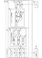
図2は、本実施形態の画像処理装置を、他の実施形態である複写機200として実装した場合の複写機200のハードウェア機能ブロックを示す。図2に示すように、複写機200は、コントローラ部210と、エンジン部240とを含んで構成される。コントローラ部210とエンジン部240とは、PCI(Peripheral Component Interconnect)バスで接続され、コントローラ部210の処理に対応してエンジン部240が起動される。コントローラ210は、複写機200の処理を制御し、描画、通信、ユーザからの入力を制御する。このため、コントローラ210は、CPU212を備えており、バスブリッジ214、216を介して、ROM/RAMからなる記憶部218およびASIC224にアクセスし、またI/O入力などを受領する。 FIG. 2 shows hardware functional blocks of the copying machine 200 when the image processing apparatus of this embodiment is mounted as the copying machine 200 according to another embodiment. As shown in FIG. 2, the copying machine 200 includes a controller unit 210 and an engine unit 240. The controller unit 210 and the engine unit 240 are connected by a PCI (Peripheral Component Interconnect) bus, and the engine unit 240 is activated in response to the processing of the controller unit 210. The controller 210 controls processing of the copying machine 200 and controls drawing, communication, and user input. For this reason, the controller 210 includes a CPU 212, accesses the storage unit 218 and the ASIC 224 made of ROM / RAM via the bus bridges 214 and 216, and receives I / O input and the like.
ASIC224は、複写機200の処理結果の外部出力を制御するための特定用途集積回路として構成され、コントローラ部210への入力を行うための操作パネル230からのユーザ入力を受領し、CPU212への指令を行うとともに、NVRAMなどで構成されるMEM−C220、HDDドライブ222などとの間の入出力制御を管理する。 The ASIC 224 is configured as an application specific integrated circuit for controlling the external output of the processing result of the copier 200, receives a user input from the operation panel 230 for inputting to the controller unit 210, and sends a command to the CPU 212. And also manages input / output control with the MEM-C 220, the HDD drive 222, and the like configured by NVRAM or the like.
ASIC224は、例えば、後述するスキャナエンジンが取得したデジタルデータに対して、圧縮処理を実行してファクシミリ送信データを作成し、ファックス送受信を制御するファクシミリコントロールユニット(FCU)232を制御して、ITU−T勧告によるG3またはG4などの規格でのファックス通信を実行する。入来したファクシミリデータを、画像データに伸張する処理を行い、伸張した画像データをエンジン部240に送付する処理を実行する。
また、ASIC224は、USB(Universal Serial Buss)234、IEEE1334バス236などを介して外部機器とのデータ送信を可能としている。エンジン部240は、PCIバスに接続可能なプリンタエンジンおよびスキャナエンジンを含んで構成される。
The ASIC 224 executes, for example, compression processing on digital data acquired by a scanner engine, which will be described later, to generate facsimile transmission data, and controls a facsimile control unit (FCU) 232 that controls facsimile transmission / reception to control ITU- Fax communication according to standards such as G3 or G4 according to the T recommendation is executed. A process of expanding the incoming facsimile data into image data is performed, and a process of transmitting the expanded image data to the engine unit 240 is executed.
The ASIC 224 can transmit data to an external device via a USB (Universal Serial Bus) 234, an IEEE 1334 bus 236, or the like. The engine unit 240 includes a printer engine and a scanner engine that can be connected to a PCI bus.
プリンタエンジンは、感光体ドラムやインクノズルを含むが像形成プロセスを使用する白黒プリンタまたはカラープリンタなどの印刷部(いずれも図示せず)を備える。なお、エンジン部240は、画像データを面積階調で表現するための誤差拡散やガンマ変換などの画像処理部分を含んで構成されていて、RGBの例えばそれぞれ8ビット深度のデジタル画像を、CMYK系の面積階調画像へと変換し、出力を可能とする。また、スキャナは、CCDなどを備えるラインスキャナなどとして構成することができ、原稿台に載置された印刷物を読み取ってデジタル変換し、RGBの8ビット深度の画像データを生成し、以後ASIC224などによる処理を可能としている。その他、CPU212は、計時機能を有し、現在日時を計時しており、図2に示した複写機200の機能は、より詳細に例えば特開2006−177990号公報に記載された構成として実装することができる。 The printer engine includes a printing unit (not shown) such as a black-and-white printer or a color printer that includes a photosensitive drum and ink nozzles but uses an image forming process. The engine unit 240 is configured to include an image processing part such as error diffusion and gamma conversion for expressing image data in area gradation, and converts RGB digital images of, for example, 8 bits each into CMYK systems. Are converted into an area gradation image and output is possible. Further, the scanner can be configured as a line scanner having a CCD or the like, and reads a printed matter placed on a platen and converts it into digital data to generate RGB 8-bit depth image data, and thereafter using an ASIC 224 or the like. Processing is possible. In addition, the CPU 212 has a clocking function and clocks the current date and time, and the functions of the copier 200 shown in FIG. 2 are implemented in more detail as a configuration described in, for example, Japanese Patent Laid-Open No. 2006-177990. be able to.
図3は、本実施形態の画像処理装置300のソフトウェア機能ブロックを示す。図3に示した画像処理装置300は、上述したようにパーソナルコンピュータとして実装されている。画像処理装置300は、アプリケーションが作成したデータを外部出力する印刷物出力機能部310と、印刷物をスキャナで読み取ってアプリケーションで処理するインデックスコード付画像取得部350とを含んで構成される。
FIG. 3 shows software function blocks of the
以下、画像処理装置300の印刷物出力機能部310と、インデックスコード付画像取得部350の機能を分離して説明する。なお、印刷物出力機能部310とインデックスコード付画像取得部350は、画像処理装置300の特定の実装型式にあっては、いずれか一方のみ実装された形態とすることができる。印刷物出力機能部310は、アプリケーション312と、グラフィックエンジン314と、プリンタドライバ316と、スプーラ318とを含んで構成される。アプリケーション312は、文書データなど、複写機やプリンタに印刷させる情報を作成するために利用されるワープロソフトウェア、表計算ソフトウェア、グラフィックソフトウェアといった汎用アプリケーションである。
Hereinafter, the functions of the printed matter
また、グラフィックエンジン314は、複写機、プリンタ、ディスプレイなどのデバイスの差異を吸収した描画用の関数インタフェースをアプリケーション312に提供するモジュールである。グラフィックエンジン314は、アプリケーション312からの関数呼び出しに応じ、文書データをアプリケーション非依存の形式の、例えばEMF(Enhanced Meta File)形式などのデータに変換し、生成されたデータをプリンタドライバ316に出力するモジュールであり、OS(Operating
System)によって提供される。例えば、Windows(登録商標)、環境においては、GDI(Graphics Device Interface)がグラフィックエンジン314の機能を提供する。また、UNIX(登録商標)、LINUX(登録商標)環境では、X−ウィンドウシステムおよびDEVMODE構造体がグラフィックスエンジン314の機能を提供する。以下、グラフィックスエンジン314により生成されたデータを描画データとして参照する。
The
System). For example, in the Windows (registered trademark) environment, GDI (Graphics Device Interface) provides the function of the
プリンタドライバ316は、本実施形態では、印刷データ作成手段として機能し、グラフィックエンジン314によって出力された描画データを、当該プリンタドライバ316が出力対象の複写機またはプリンタが処理可能な形式、例えばPDL(Page Description Language)、以下「印刷データ」として参照する。)に変換する。描画データから印刷データを作成する処理は、従来と同様の処理を使用する。しかしながら、本実施形態におけるプリンタドライバ316は、描画データを印刷データに変換する処理中に、描画データをインデックスコード付画像作成手段として機能するインデックスコード付画像作成部330に渡し、描画データに追加するコード情報の描画データ中での領域を示すインデックスコードを生成させる。その後、インデックスコード付画像作成部330は、インデックスコードを元の描画データに付加してプリンタドライバ316に戻し、インデックスコード付の描画データを印刷データに変換する処理を実行する。
In this embodiment, the
スプーラ318は、印刷ジョブを記憶しておき、印刷データを、印刷指令の順にプリントアウトできるようにするキュー手段として機能するモジュールである。スプーラ318は、プリンタドライバ316から印刷データを受取り、画像形成エンジン320へと印刷データの受領した順で印刷データを送る。なお、画像形成エンジン320は、複写機、プリンタなど画像形成機能を提供する機能部を総称するものとして参照する。
The
なお、機能説明を明確化する目的から、プリンタドライバ316と、インデックスコード付画像作成部330とを異なる機能モジュールとして説明するが、インデックスコード付画像作成部330は、プリンタドライバ316の機能モジュールとして実装することもできる。
For the purpose of clarifying the function description, the
以下、インデックスコード付画像作成部330の処理について説明する。インデックスコード付画像作成部330は、描画データを受取り、ユーザが当該描画データに追加することを指令したコード情報について、エンコード種類、描画データ中での領域範囲を示す範囲情報、および画像の回転角度などの要素情報をエンコードして、インデックスコード画像とし、当該インデックスコード画像を付加した描画データを生成するモジュールである。 Hereinafter, processing of the index code-added image creation unit 330 will be described. The index code-added image creation unit 330 receives the drawing data, and for the code information that the user commands to add to the drawing data, the encoding type, the range information indicating the area range in the drawing data, and the rotation angle of the image This is a module that encodes element information such as to generate an index code image and generates drawing data to which the index code image is added.
インデックスコード付画像作成部330は、コード配置情報取得部332と、デコーダ334とを含んで構成されている。コード配置情報取得部332は、描画データを受け取って描画データ中に含まれるコード情報を解析し、コード情報が描画データ中に示す領域情報、コード種類情報などを取得してコード配置情報リストを生成する、コード配置情報取得手段として機能する。また、デコーダ334は、コード配置情報取得部332が取得した描画データを解釈し、デコード結果をコード配置情報取得部332に返し、描画データ中にコード情報が含まれているか否かの判断を可能とさせている。さらに、インデックスコード付画像作成部330は、インデックスコード作成部336と、エンコーダ338と、画像合成処理部340とを含んで構成されている。
The image generation unit with index code 330 includes a code arrangement
インデックスコード作成部336は、コード配置情報取得部332が作成したコード配置情報リストを受け取って、エンコーダ338に渡し、エンコード後のコード配置情報リストを受領して設定されたコード種類でのインデックスコード画像を生成する、インデックスコード作成手段として機能する。エンコーダ338は、指定された文字列やバイト配列等を1次元バーコードや2次元コードの画像に符号化する。1次元バーコードとしては、Code39、EAN−8、EAN−13、NW−7、Code128などを挙げることができる。また、2次元コードとしては、QR、DataMatrix、PDF417等を挙げることができる。デコーダ334は、上述した1次元バーコードや2次元コードの画像から元の文字列やバイト配列を復号する。デコーダ334およびエンコーダ338については、公知の技術を使用して実装することができる。画像合成部340は、描画データにインデックスコード画像のデータを追加し、インデックスコード付画像を生成する、画像合成手段として機能する。
The index
画像合成部340で作成されたインデックスコード付画像は、プラインタドライバ316において、PDLに変換され、PJL(Printer Job Language)などのプリンタ制御言語が付加されて、印刷データとされ、スプーラ318に転送される。スプーラ318は、印列データを、IEEE1294、USB、イーサネット(登録商標)などのバス、またはネットワークを介して画像形成エンジン320に送付する。複写機、プリンタなどとして実装することができる画像形成エンジン320は、プリンタ制御言語を使用して、送付されたインデックスコード付画像を含む印刷データについて、印刷処理を実行する。なお、画像を印刷する場合に、拡大や縮小を行う場合、画像合成部340は、拡大縮小率に対応してインデックスコード画像の印刷位置を修正する。
The index code-added image created by the
図3に示す画像処理装置300は、またインデックスコード付画像取得部350を含んでいる。図3に示した実施形態では、画像処理装置300は、TWAINドライバ354を起動してスキャナ356から画像データを取得する。取得した画像データは、画像処理を実行するアプリケーション352に送られる。アプリケーション352は、OCRソフトなどの画像処理を可能とするアプリケーションのモジュールとして実装することができる。アプリケーション352は、受領したインデックスコード付画像を、インデックスコード付画像読取手段として機能する、インデックスコード付画像読取部360に送付する。インデックスコード付画像読取部360は、さらにインデックスコード読取部364と、一般コード情報読取部366と、デコーダ362とを備えている。
The
読取られた画像データは、インデックスコード読取手段として機能するインデックスコード読取部364と、コード情報をデコードした制御情報として機能する一般コード情報を提供する一般コード情報読取部366とに入力される。インデックスコード読取部364は、スキャンされたインデックスコード付画像を受取ってコード配置情報リストを復号するモジュールである。一般コード情報読取部366は、画像データとコード配置情報リストとを受け取って画像データ中に含まれる一般コードの位置、エンコード種類、デコードされたバイト列情報などを指定する一般コード情報リストを生成する。デコーダ362は、1次元バーコードや2次元コードの画像から元の文字列やバイト配列を復号するモジュールであり、デコーダ334と同様の機能を有している。なお、一般コード情報は、画像処理装置300の読込画像に関してアプリケーション352が実行する処理を制御する制御情報として機能し、制御情報に基づいて、画像処理装置300は、画像編集、複製出力、画像転送などの処理を実行する。
The read image data is input to an index
なお、図3に示す画像処理装置300は、インデックスコード付画像作成部330とインデックスコード付画像読取部360とを同時に含む場合、デコーダ334、デコーダ362、およびエンコーダ338とをコーデックとして機能的に統合し、共用することができる。また、図3に示した実施形態では、アプリケーション312およびアプリケーション352は、例えば同一のドキュメント管理アプリケーション、ドキュメント作成アプリケーション、画像処理アプリケーションなどの、それぞれ出力モジュールおよび読取りモジュールとして実装することができる。
When the
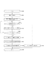
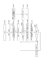
図4は、図3に示したインデックスコード付画像作成部330が実行する処理の実施形態のフローチャートである。図4の処理は、ステップS400から開始し、ステップS401で描画データを受取る。ステップS402では、描画データをコード配置情報取得部332が解析し、画像データ部分を抜き出す。なお、ステップS402で解析する描画データの構成についてはより詳細に後述する。ステップS403では、描画データに未処理の画像データがあるか否かを判断する。未処理の画像データがない場合(no)、処理をステップS407に分岐させ、コード配置リストを返し、ステップS408で処理を終了する。
FIG. 4 is a flowchart of an embodiment of processing executed by the index code-added image creation unit 330 shown in FIG. The process in FIG. 4 starts from step S400, and drawing data is received in step S401. In step S402, the code arrangement
一方、ステップS403で、未処理の画像データがあると判断された場合(yes)、処理をステップS404に分岐させ、画像データをデコーダ334に渡し、デコード結果を生成する。その後ステップS405でデコード成功か否かを判断し、デコードが不成功であった場合(no)、処理をステップS403に分岐させ、さらに未処理の画像の有無を判断する。ステップS405で、デコードが成功した場合(yes)、ステップS406でコード配置情報リストに新に検出されたコード情報を追加し、コード配置情報リストを更新する。なお、デコードの成功・失敗の判断は、デフォルトのコード情報について失敗した場合でも、コード配置情報取得部332が処理画像領域を例えば90°ごとに回転させ、デコードの角度による成功・失敗を判断し、その回転角度の値を生成する処理も実行する。その後、処理をステップS403に戻し、さらに残りの画像データについての処理を反復させる。
On the other hand, if it is determined in step S403 that there is unprocessed image data (yes), the process branches to step S404, the image data is passed to the
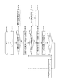
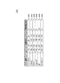
図5は、図4の処理で使用する描画データ500、付随データ510、およびコード配置情報リスト520のデータ構造の実施形態を示した図である。図5に示す描画データ500は、描画コマンド1と、描画コマンド1に対応する付随データ1とが対となって描画を制御する。また、同様に、描画データ500は、描画コマンド2、描画コマンド3などを含み、それぞれに対応する付随データ2、3を登録して構成されている。なお、描画コマンドは、DEVMODE構造体などにより指定される文字、画像、ベクタなどの画像種類に対して、それぞれの位置情報を登録した構造として構成される。
FIG. 5 is a diagram showing an embodiment of the data structure of the drawing
付随データ510は、付随データのデータ構成を示した実施形態を示す。データ構造510は、例えば文字列を記述する描画コマンド、画像を記述する描画コマンド、ベクタを記述する描画コマンドに対し、付随データ510として、文字列、位置、サイズ、色の各情報が対応して付随データ512、514、516として登録されている。コード配置情報取得部332は、プリンタドライバ316は、描画データ500を一旦バッファリングし、コード配置情報取得部332へと描画データ500を渡してデコーダ334によるデコード処理を実行させ、描画データが含むコード情報を取得する。
The accompanying
取得したコード情報は、コード配置情報リスト520に、コード種類、その範囲情報、および回転角度を対応させたレコード522〜レコード530とし、配置情報として登録される。また、デコーダによるデコード結果が失敗した場合には、コード配置情報取得部332は、適切な角度ごとに描画データを回転させ、デコード処理を設定された角度ごとに画像を回転変換することによって試行する。そして、コード配置情報リスト520には、コード配置情報取得部332がコード情報のデコードに成功したときのコード情報の回転角度を、「度」単位で登録する。なお、パーソナルコンピュータ300が作成するコード情報の配置が予め規定されている場合には、回転角度(deg)のフィールドは、必要ではない。
The acquired code information is registered as arrangement information in the code
図5に示した実施形態では、コードの範囲情報は、例えば描画データの左上を原点としたときのコード画像の左上隅の(xl,yl)座標および右下隅の(xr、yr)座標の各値を、適切な単位、例えばmm(ミリメートル)で示した値を使用して登録されている。しかしながら、本実施形態では、コード画像の四隅のカーテジアン座標を範囲情報として使用することもできるし、単位についてもミリメートルではなくインチを使用して表現することもできる。また、コードの回転角度についても、degで表現する他、他の単位や表現を用いることができる。さらに、コード配置情報の登録データは、図5の実施形態に限定されるものではなく、登録フィールドとして登録されたデータ種類のうち、不要な場合には不要な要素情報登録する必要は無いし、またさらに追加するべき情報がある場合には要素情報のフィールドを追加することができる。追加することができる要素情報としては、例えばコードサイズに関連する情報、例えば、1次元バーコードやスタック型2次元コードの最細バー幅、マトリクス型2次元コードのセルサイズなど、後述の一般コード読み取り処理時のデコード処理をサポートするような付加情報を挙げることができる。 In the embodiment shown in FIG. 5, the code range information includes, for example, the (x l , y l ) coordinates of the upper left corner of the code image and the (x r , y r ) of the lower right corner when the upper left corner of the drawing data is the origin. ) Each coordinate value is registered using an appropriate unit, for example, a value expressed in mm (millimeter). However, in this embodiment, Cartesian coordinates at the four corners of the code image can be used as range information, and the unit can be expressed using inches instead of millimeters. Also, the rotation angle of the code can be expressed in deg, and other units and expressions can be used. Further, the registration data of the code arrangement information is not limited to the embodiment of FIG. 5, and it is not necessary to register unnecessary element information when unnecessary among the data types registered as the registration field, If there is more information to be added, an element information field can be added. As element information that can be added, for example, information related to the code size, for example, a general code described later such as the one-dimensional barcode, the thinnest bar width of the stack type two-dimensional code, the cell size of the matrix type two-dimensional code, etc. Additional information that supports decoding processing during reading processing can be given.
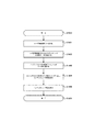
図6は、インデックスコード作成部336がインデックスコードを作成する処理の実施形態についてのフローチャートである。インデックスコード作成処理は、ステップS600から開始し、ステップS601でコード配置情報リスト520を受領する。ステップS602では、コード配置情報リスト520からインデックスコード作成データを作成する。インデックスコード作成用データとは、コード配置情報リスト520に登録されたレコードに含まれる文字列、数値などをバイト配列に変換したデータを意味する。ステップS603では、インデックスコード作成用データをエンコーダ338に渡し、インデックスコード画像を作成する。インデックスコード画像は、コードの種類は限定されないが、インデックスコード画像のサイズを小さくする点で、1次元バーコードよりも2次元コードを用いる方が望ましい。インデックスコード画像のエンコードが終了した段階でインデックスコード作成部336は、ステップS604で作成したインデックスコード画像を画像合成部340に渡して処理を終了する。
FIG. 6 is a flowchart of an embodiment of a process in which the index
図7は、画像合成部340が実行する処理のフローチャートである。図7の処理は、ステップS700から開始し、ステップS701で、バッファメモリから描画データを読出し、また画像合成部340がバッファリングしておいたインデックスコード画像を読み出す。ステップS702では、描画データを画像データに対応する付随データとして、インデックスコード画像の位置、サイズなどの情報を追加する。ステップS703で、画像合成が終了したインデックスコード付画像をプリンタドライバ316に返し、バッファリングさせ、処理をステップS704で終了させる。
FIG. 7 is a flowchart of processing executed by the
プリンタドライバ316は、受領した描画データをPDLに変換し、プリンタ制御言語のコードを追加した後、スプーラ318に渡す。スプーラ318は、画像形成エンジン320と通信してインデックスコード付画像を画像形成エンジン320に転送する。画像形成エンジン320は、受領した印刷データを、プリンタ制御言語を使用して印刷データの印刷を実行することで、インデックスコード付画像の印刷が完了する。
The
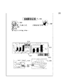
図8は、本実施形態の画像処理装置300が作成した電子ドキュメント800の実施形態を示す。図8に示した電子ドキュメント800は、複数の画像データ802〜824が存在している。画像処理装置300は、図8に示す印刷物を与えるこの電子ドキュメント800に対するプリント指令を受領すると、グラフィックエンジン314によってコード情報を含む電子ドキュメントを描画データに変換する。描画データは、その後、プリンタドライバ316に渡される。プリンタドライバ316は、描画データをインデックスコード付画像作成部332に渡す。
FIG. 8 shows an embodiment of an
インデックスコード付画像作成部316は、コード配置情報取得部332は、描画データ中の画像データ802〜824を抽出する。抽出された画像データは、図5に示した描画コマンドの付随情報を抽出することによって取得される。そして、画像データ802〜824は、それぞれデコーダ334に渡されて、デコードが試行されるので、画像データがコード画像である場合は確実にデコードが可能である。図8の電子ドキュメント800では、画像データ802(Code39)、810(PDF417)、816(Code128)、820(QR)、824(DataMatrix)についてデコード試行が成功したものとして説明する。デコード結果は、コード配置情報リスト520に追加され、生成されたコード配置情報リスト520がインデックスコード付画像作成部336に渡される。
The
インデックスコード付画像作成部336は、コード情報リスト520をインデックスコード作成部336に渡し、コード情報リスト520からインデックスコード作成用データをバイト列として生成する。作成されたインデックスコード作成用データは、エンコーダ338に渡され、インデックスコード画像が作成される。作成されたインデックスコード画像は、画像合成処理部340に渡され、付属データを画像として規定する描画コマンドに対応する付属データの画像として、その、画像、位置およびサイズなどの情報を記述して画像合成を完了する。作成されたインデックスコード付画像は、プリンタドライバ316へと渡され、印刷データとされ、スプーラ318を介して画像形成エンジン320に転送され、印刷物が作成される。
The index code-added
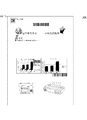
図9は、図8で説明した処理を経て画像形成エンジン320から出力された印刷物900の実施形態を示す。印刷物900は、電子ドキュメント800に対応する画像を、指定された印刷用紙上に形成している。また、画像処理装置300が作成したインデックスコード画像910が合成されており、合成されたインデックスコード画像910は、図9に示した実施形態では、印刷物の左上の文書・画像認識性に影響を与えない領域に追加されているのが示されている。なお、他の実施形態ではインデックスコード画像は、印刷物900の左右上下に4箇所形成させることもできる。左右上下の4箇所に作成する場合には、印刷物をスキャナにより読み込ませる場合の読み取り方向によらず効率的にインデックスコード画像を取得することが可能となる。また、インデックスコード画像を複数形成する場合には、それぞれコード情報の内容を変更し、インデックスコード画像全部が取得された段階で、全コード情報を与えるように、コード情報の内容を互いに変えることもできる。
FIG. 9 shows an embodiment of a printed
図10は、本実施形態の画像処理装置がインデックスコート付画像の読取りを実行する場合、インデックスコード読取部360が実行する処理のフローチャートを示す。インデックスコード付画像の読み取り処理は、ステップS1000から開始し、ステップS1001で、スキャナなどが取得した画像データを受取る。ステップS1002では、画像中の領域をインデックスコード抽出の目的で切り出す。ステップS1003では、未処理の領域があるか否かを判断し、未処理の領域がない場合(no)処理をステップS1010に分岐させ、デコード失敗のエラー通知を返し、処理をアプリケーションに返し、処理を終了する。
FIG. 10 shows a flowchart of processing executed by the index
一方、ステップS1003で未処理の領域がある場合(yes)、ステップS1004で切り出した領域をインデックスコード読取部364に渡し、ステップS1005で、デコーダ362を呼出し、デコード試行を実行する。なお、ステップS1005のデコード試行は、切り出した領域について、デコード失敗した場合でも、角度を修正しながら、デコード試行を行う。デコード試行が結果的に成功しなかった場合(no)、処理をステップS1003に戻し、他の領域の判断を実行させる。また、ステップS1005でデコードに成功した場合(yes)、処理をステップS1006に分岐させ、デコード結果からコード配置情報リストを取得する。さらにステップS1007では、デコードされたインデックスコードの回転角度を取得し、画像読取りの読み取り角度を取得し、読み取り角度およびデコードしたコード配置情報リスト520を後述する一般コード情報読取部366に返し、ステップS1009で処理を終了させる。
On the other hand, if there is an unprocessed area in step S1003 (yes), the area cut out in step S1004 is transferred to the index
図11は、読取り角度およびデコードしたコード配置情報リスト520を取得した一般コード情報読取部366が実行する処理の実施形態を示す。図11に示す一般コード情報読取部366の処理は、ステップS1100から開始し、ステップS1101で画像データを受領し、ステップS1102で画像の向きとコード配置情報リストを受け取ったか否かを判断する。ステップS1102で、画像の向きとコード配置情報リストを受け取っていないと判断された場合(no)、画像データの全域探索を行い、一般コード情報の取得を行い、ステップS1111で、アプリケーションに対して一般コード情報リストを返し、処理をステップS1112で終了させる。
FIG. 11 shows an embodiment of processing executed by the general code
また、ステップS1102で、画像の向きとコード配置情報リストを受け取ったと判断された場合(yes)、ステップS1104で画像データを画像向きの一致させるように回転変換を行い、ステップS1105で、未処理のコード配置情報があるかを判断する。なお、画像の向きの一致処理は、画像データ全体を画像の向きに合わせて回転させた後に画像データの領域切り出し処理をおこなうこともできるし、画像全体の回転を行う代わりに、切り出し領域を画像の向きに合わせて補正するようにしてもよい。切り出し領域の方向を修正する場合、画像データ全体を処理しなくて済むため、処理速度が向上する。未処理のコード配置情報が無いと判断された場合(no)、ステップS1111に処理を分岐させ、一般コード情報リストをアプリケーションに返し、ステップS1112で処理を終了させる。 If it is determined in step S1102 that the image orientation and code arrangement information list have been received (yes), in step S1104, rotation conversion is performed so that the image data matches the image orientation. In step S1105, an unprocessed image is processed. Determine if there is code placement information. In the image orientation matching process, the entire image data can be rotated in accordance with the orientation of the image, and then the image data area extraction process can be performed. You may make it correct | amend according to direction. When correcting the direction of the cutout region, it is not necessary to process the entire image data, so that the processing speed is improved. If it is determined that there is no unprocessed code arrangement information (no), the process branches to step S1111 to return the general code information list to the application, and the process ends in step S1112.
ステップS1105の判断で未処理のコード配置情報があると判断された場合(yes)、ステップS1106でコード配置情報を基に画像データの領域を切り出し、ステップS1107で切り出した領域の画像をコード配置情報で指定されるデコーダに渡し、デコード結果を作成する。ステップS1108では、デコードが成功したか否かを判断し、デコードに成功しない場合(no)、処理をステップS1105に戻し、処理を繰り返す。また、ステップS1108でデコードが成功した場合(yes)、処理をステップS1109に分岐させ、一般コード情報リストを更新する。その後、さらに未処理の領域があるか否かを、処理をステップS1105に戻して、未処理のコード配置情報が無くなるまで処理を反復させる。 If it is determined in step S1105 that there is unprocessed code arrangement information (yes), an area of image data is extracted based on the code arrangement information in step S1106, and an image of the area extracted in step S1107 is code arrangement information. The result is passed to the decoder specified by, and the decoding result is created. In step S1108, it is determined whether or not the decoding is successful. If the decoding is not successful (no), the process returns to step S1105 and the process is repeated. If the decoding is successful in step S1108 (yes), the process branches to step S1109, and the general code information list is updated. Thereafter, the process returns to step S1105 to determine whether or not there is an unprocessed area, and the process is repeated until there is no unprocessed code arrangement information.
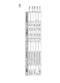
図12は、一般コード情報読取部366が生成する一般コード情報リスト1200の実施形態を示す。一般コード情報リスト1200は、コードごとにリストのレコード1202〜1210が形成されており、レコード内には、コードを特徴付けるための情報が登録されており、各列がコード情報のそれぞれ対応する情報を与えている。一般コード情報を構成する要素情報としては、コードの種類、デコードデータ、コードの位置情報、コードの回転角度などを登録することができる。コード種類、コードの位置情報、コードの回転角度は、コード配置情報リスト520のエンコード種類、範囲情報、回転角度と同様の機能を有する情報である。
FIG. 12 shows an embodiment of the general
また、デコードデータには、図11のステップS1107のデコード処理によって得られた文字列などのバイト配列が格納される。なお、一般コード情報リスト1200に登録できる要素情報は、図12に示した情報に限定されるものではなく、要素情報を適宜削減したり、追加することができる。例えば、追加することができる要素情報としては、例えば誤り訂正レベルや特定産業規格(Industrial Standard)の情報など、デコード処理によって得られる他の情報を追加してもよい。
In the decoded data, a byte array such as a character string obtained by the decoding process in step S1107 in FIG. 11 is stored. The element information that can be registered in the general
図13を参照してアプリケーション352がスキャナ356を使用して画像を取得し、取得した画像データから一般コード情報リスト1200を生成するまでの処理の実施形態を説明する。図13に示した実施形態では、図9に示した画像をスキャナ356によって読み込むものとする。
With reference to FIG. 13, an embodiment of processing until the application 352 acquires an image using the
スキャナ356に図9に示した画像を載置して、読取り指令を受領したアプリケーション352は、TWAINドライバ354を呼出し画像900の読み取り処理を実行し、図13に示されるスキャン画像1300を得る。アプリケーション352は、スキャン画像1300のデータをインデックスコード付画像読取部360に渡す。その後、インデックスコード付画像読取部360は、スキャン画像をインデックスコード読取部364に渡す。
The application 352 that has placed the image shown in FIG. 9 on the
スキャン画像1300は、インデックスコード付画像読取部360に渡されると、インデックスコード読取部364は、スキャン画像1300中でインデックスコード画像の存在する可能性のある領域として規定される四隅領域1302、1306、1314、1316を切り出す。切り出した領域1302〜1316は、デコーダ362に渡され、デコード結果が生成される。図13に示した実施形態では、領域1306にコード画像が形成されている。領域1306について、インデックスコードのデコード試行処理では、コード画像の回転が行われ、図示した実施形態では、回転角度270°時計回りにコード画像を回転させた段階でデコードが成功するものとして、以下さらに説明する。
When the scanned
デコード結果は、図5に示したコード配置情報リスト520をアプリケーション352に対して取得させ、デコードしたインデックスコード画像の向き情報および領域1306の位置から、スキャン画像1300の読み取り方向が時計周りに270°回転されていたことが判断される。この判断の結果、アプリケーション352は、取得したコード配置情報リスト520と、スキャン画像1300の向き情報とをインデックスコード付画像読取部360に渡す。
As a result of decoding, the code
次いで、インデックスコード付画像読取部360は、スキャン画像1300と、コード配置情報リスト520と、スキャン画像の向き情報とを、一般コード情報読取部366に渡す。一般コード情報読取部366は、コード配置情報リスト520と、スキャン画像1300の向き情報とを使用して、領域1304、1308、1312、1318、1320を切り出す。そして切り出した領域1304、1308、1312、1318、1320のそれぞれを、デコーダ362に渡し、デコードを実行する。その結果、切り出した領域1304、1308、1312、1318、1320に含まれる画像は、コード配置情報リスト520に登録されたエンコード方式Code39、PDF417、Code128、QR、DataMatrixを使用しながらも、各コード画像に対してそれぞれのエンコード方式をトライアンドエラーさせることなくデコードされる。
Next, the index code-added
また、図12に示す一般コード情報リスト1200は、本実施形態により、デコード結果から高精度、かつ高速に作成することができる。その後、一般コード情報リスト1200は、インデックスコード付画像読取部360に渡される。インデックスコード付画像読取部360は、取得した一般コード情報リスト1200をアプリケーション352に返し、一般コード情報を使用した後続処理を可能とする。
In addition, the general
以上の例では、画像処理装置300のアプリケーション352がTWAINドライバ354を介して画像データを取得するものとして説明した。しかしながら、他の実施形態では、画像データを取得できる限り他のシーケンスを用いることができる。例えば、複写機として実装された画像形成エンジン320が読み取った画像データをファイル化し、画像ファイルをネットワーク上の任意のストレージ領域に保存しておく。アプリケーション352は、保存された画像ファイルにアクセスし、FTP、HTTPなどのファイル転送プロトコルを使用して画像ファイルをダウンロードし、上述したデコード処理に提供することもできる。
In the above example, the application 352 of the
以上説明したように、本実施形態では、写真や図表などとともに任意の位置・大きさ・回転角度で埋め込まれた複数多種のエンコード方式を有するコード情報を含む電子ドキュメントについて、高精度・短時間での高効率のコード認識が可能となる。また、印刷処理時にインデックスコードを四隅のいずれかに付与し、読取処理時にインデックスコード検出領域として四隅領域をとるようにすることで、スキャン時の紙原稿の向きによらずに確実にコードを認識させることができる。さらに、本実施形態は、特定の文書作成アプリケーションに限定されることなく、汎用的な電子文書作成アプリケーションによって作成された電子文書に対して適用可能である。 As described above, in this embodiment, an electronic document including code information having a plurality of various encoding methods embedded at an arbitrary position, size, and rotation angle together with a photograph, a chart, and the like can be obtained with high accuracy and in a short time. Highly efficient code recognition. In addition, an index code is assigned to one of the four corners during the printing process, and the four corner areas are taken as the index code detection area during the reading process, so that the code can be reliably recognized regardless of the orientation of the paper document during scanning. Can be made. Furthermore, the present embodiment is not limited to a specific document creation application, and can be applied to an electronic document created by a general-purpose electronic document creation application.
以下、図14を参照して、画像処理装置の第2の実施形態について説明する。第2の実施形態の画像処理装置1400は、機能ブロックとしては第1の実施形態の画像処理装置と同様の構成を備える。しかしながら、各機能ブロックが画像処理装置として実装されるパーソナルコンピュータ1410と、複写機1430とに分離して実装される点で、第1実施形態の画像処理装置とは相違する。
Hereinafter, the second embodiment of the image processing apparatus will be described with reference to FIG. The
図14に示す画像処理装置1400は、パーソナルコンピュータ1410と、パーソナルコンピュータ1410がネットワークプリンタなどとして接続する複写機1430として実装されている。インデックスコード付画像作成部1450は、複写機1430の機能モジュールとして実装され、パーソナルコンピュータ1410は、専らコード情報を埋め込む処理を実行する。図14に示した実施形態では、プリンタドライバ1416は、既存のものが利用され、複写機1430の機能モジュールが、本実施形態のインデックスコード付画像を作成する。
An
なお、図14に示すインデックスコード付画像作成部1450は、第1の実施形態で説明したと同様の機能を提供している。第2の実施形態では、コード配置情報取得部1452および画像合成処理部1456は、描画データではなく、プリンタ制御言語のコマンドを含むPDLなどのフォーマットで作成された印刷データを解析することを除き、第1の実施例と同様の処理を実行するため、これ以上の詳細な説明は省略する。第2の実施形態では、インデックスコード付画像の作成を複写機の機能として提供することができる。
Note that the index code-added image creating unit 1450 shown in FIG. 14 provides the same functions as described in the first embodiment. In the second embodiment, the code arrangement
図15は、第3の実施形態の画像処理装置1500を示す。第3の実施形態の画像処理装置1500は、インデックスコード付画像読取部1510は、第1の実施形態と同様の機能モジュールを含んで構成される。しかしながら、第3の実施形態では、読取処理シーケンスでスキャナ1530からの画像データを使用してインデックスコードを読取り、一般コード情報リスト生成処理を実行する点で相違する。図15の画像処理装置1500を詳細に説明すると、画像処理装置1500は、スキャナ1530と、スキャナを制御し、ラスタデータなどにイメージ変換し、さらに処理要求を外部から受領して画像に対して各種の処理を実行するアプリケーションとを含んでいる。読取られた画像データは、インデックスコード読取手段として機能するインデックスコード読取部1512と、コード情報をデコードした制御情報として機能する一般コード情報を提供する一般コード情報読取部1514とに入力される。インデックスコード読取部1512は、スキャンされたインデックスコード付画像を受取ってコード配置情報リストを復号するモジュールである。一般コード情報読取部1514は、画像データとコード配置情報リストとを受け取って画像データ中に含まれる一般コードの位置、エンコード種類、デコードされたバイト列情報などを指定する一般コード情報リストを生成する。デコーダ1516は、1次元バーコードや2次元コードの画像から元の文字列やバイト配列を復号するモジュールであり、デコーダ334と同様の機能を有している。なお、一般コード情報は、画像処理装置1500の読込画像に関してアプリケーション1520が実行する処理を制御する制御情報として機能し、制御情報に基づいて、画像処理装置300は、画像編集、複製出力、画像転送などの処理を実行させている。
FIG. 15 shows an
画像処理装置の第4の実施形態では、画像処理装置は、インデックスコード付画像に、インデックスコードを複数画像データに配置する処理を実行する。第4の実施形態では、インデックスコード画像は、画像処理装置300により指定される描画データの複数の指定領域、例えば四隅に配置される。四隅に配置されるインデックスコード画像は、すべて同一の情報(全ての一般コードの配置情報)をエンコードすることができる。上述したインデックスコードを使用することにより、インデックスコード読取処理時に一部のインデックスコードが読めなかった場合でも残りのインデックスコードから一般コード情報リストを取得でき、コード認識精度を向上させることができる。
In the fourth embodiment of the image processing apparatus, the image processing apparatus executes processing for arranging an index code in a plurality of image data on an image with an index code. In the fourth embodiment, index code images are arranged in a plurality of designated areas, for example, four corners, of drawing data designated by the
また、全てのインデックスコードに同じ情報(全ての一般コードの配置情報)をエンコードすることに代えて、各インデックスコードに一般コードの配置情報を分散してエンコードするように実装することができる。各インデックスコードに一般コードの情報を分散して配置することにより、インデックスコード1つあたりの画像サイズを小さく抑えることができ、文書のレイアウトや見た目に対する影響を低減させることができる。 Further, instead of encoding the same information (all general code arrangement information) in all index codes, the general code arrangement information can be distributed and encoded in each index code. By disposing the general code information in each index code, the image size per index code can be kept small, and the influence on the layout and appearance of the document can be reduced.
以下、画像処理装置の第5の実施形態について説明する。画像処理装置の第5の実施形態では、機能モジュール構成は、第1の実施形態のものと同様に実装される。しかしながら、インデックスコード作成部336およびコード配置情報取得部332の処理が異なる。図16は、画像処理装置の第5の実施形態におけるインデックスコード作成部336の処理のフローチャートである。図6の処理とは異なり、図16の処理では、インデックスコード作成用データをエンコーダに渡す前に、ステップS1603でインデックスコード作成用データにヘッダデータを付加する。
The fifth embodiment of the image processing apparatus will be described below. In the fifth embodiment of the image processing apparatus, the functional module configuration is implemented in the same manner as in the first embodiment. However, the processes of the index
ヘッダデータは、例えば24ビットの固定長データとして構成することができ、後述するインデックスコード読取部の処理において、インデックスコードを、一般のコードとの区別を容易に識別するための識別データとして用いられる。第5の実施形態では、画像データ中に複数のコード情報が存在する場合であってもデコード処理を排除して直接インデックスコードを識別することができ、インデックスコード画像を付加する位置を予め定めずとも、画像データの特性に応じて適切な箇所に埋設することが可能となる。 The header data can be configured as, for example, 24-bit fixed-length data, and is used as identification data for easily identifying the index code from a general code in the processing of the index code reading unit described later. . In the fifth embodiment, even when there are a plurality of pieces of code information in the image data, the index code can be identified directly by eliminating the decoding process, and the position where the index code image is added is not determined in advance. In both cases, it is possible to embed it in an appropriate location according to the characteristics of the image data.
図17は、画像処理装置の第5の実施形態で、コード配置情報取得部332が実行する処理のフローチャートである。図10とは、ステップS1006で、デコード結果からコード配置情報リストを取得する処理を実行する前に、ステップS1706でデコードデータがインデックスコードのデータかを判断する。説明する実施形態では、デコードデータの最初の3byte(24ビット)の固定長データが、インデックスコードを示す値と一致しているか否かを比較する。ステップS1706でデコードデータがインデックスコードのデータであると判断された場合(yes)、ステップS1707でコード配置情報リストを取得し、ステップS1708で画像の向き情報の取得を行い、ステップS1710で取得した情報をアプリケーションに返し、ステップS1711で処理を終了させる。
FIG. 17 is a flowchart of processing executed by the code arrangement
一方、ステップS1706でデコードデータがインデックスコードのデータでない(一般コードのデータである)と判断された場合(no)、処理をステップS1703に戻し、未処理の領域があるか否かを判断し、未処理の領域が無くなるまで、処理を反復させる。
図16および図17に示した処理を使用することで、インデックスコード検出領域に一般コードが含まれている場合でも一般コードをインデックスコードとみなして処理することがなくなるので、誤動作を防止し、検出効率を高めることが可能となる。
On the other hand, if it is determined in step S1706 that the decoded data is not index code data (general code data) (no), the process returns to step S1703 to determine whether there is an unprocessed area. The process is repeated until there are no unprocessed areas.
By using the processing shown in FIG. 16 and FIG. 17, even when a general code is included in the index code detection area, the general code is not considered to be processed as an index code, thereby preventing malfunction and detection. Efficiency can be increased.
なお、第5の実施形態では、インデックスコードを一般コードと区別するための識別データとしての固定長データを、インデックスコード作成データの先頭に付加するものとして説明した。さらに他の実施形態では、例えば固定長データをインデックスコード作成データの末尾に付加することもできる。さらに、他の実施形態では、インデックスコード作成データからSHA−1、MD−5などの既知の一方向関数を使用してハッシュ値を算出し、ハッシュ値を識別データとして使用することもできる。 In the fifth embodiment, the fixed length data as identification data for distinguishing the index code from the general code is described as being added to the head of the index code creation data. In still another embodiment, for example, fixed-length data can be added to the end of the index code creation data. In another embodiment, a hash value can be calculated from index code creation data using a known one-way function such as SHA-1 or MD-5, and the hash value can be used as identification data.
以下、図18、図19を使用して本発明の第6の実施形態における画像処理装置について説明する。第6の実施形態における画像処理装置は、第1の実施形態を同様に実装することができるが、コード配置情報リストおよびインデックスコード読取部364、一般コード情報読取部366での処理が異なる。図18は、第6の実施形態の画像処理装置が使用するコード配置情報リスト1800である。なお、図18に示すコード配置情報リストは、図5のコード配置情報リスト520と比較し、インデックスコード自身の位置および回転角度の情報を格納するレコードが追加されている点に留意されたい。
The image processing apparatus according to the sixth embodiment of the present invention will be described below with reference to FIGS. The image processing apparatus according to the sixth embodiment can similarly implement the first embodiment, but the processing in the code arrangement information list and index
図19は、第6の実施形態におけるインデックスコード読取部364の処理のフローチャートである。処理は、図10に示した処理とは、ステップS1907で画像の向き情報ではなく、デコードされたインデックスコードの位置・回転角度を一般コード情報読取部366に返すことを除き、図10の処理と同様にして処理が実行される。また、図20は、本発明の第6の実施形態におけるインデックスコード読取部364の処理のフローチャートを示す。図20に示した実施形態は、図11の処理とは、画像の向き情報ではなく、ステップS2002で、デコードされたインデックスコードの位置・回転角度を受取り、以後の処理に利用する点で相違する。
FIG. 19 is a flowchart of the process of the index
さらに、ステップS2004では、画像データの位置補正を実行する点で相違する。その他の処理ステップは、図10の処理と共通するので詳細な説明は省略する。ステップS2004の位置補正処理は、インデックスコード読取部364は、コード情報リスト1800に記載されているインデックスコードの位置・回転角度と、実際にデコードされたインデックスコードの位置・回転角度とを比較し、位置および回転角度が、それぞれ一致するように画像データを回転・並進移動を行う処理を実行する。
Further, step S2004 is different in that position correction of image data is executed. The other processing steps are the same as the processing in FIG. In the position correction process of step S2004, the index
第6の実施形態では、スキャン時に紙文書がある程度ずれている場合でもスキャン画像のズレを補正することができ、一般コード情報の領域を適切に切り出すことが可能になり、コード認識精度を向上させることができる。第6の実施形態では、ステップS2004で画像データの位置補正処理を行った後、ステップS2006で画像データの領域切り出し処理を行なうものとして説明している。しかしながら、さらに他の実施形態では、画像全体の位置補正処理を行う代わりに、ステップS2006で切り出し領域について位置補正を実行するようにしてもよい。説明する他の実施形態では、画像データ全体について回転および並進移動処理を実行する必要が無くなるのでさらに、処理速度を向上させることができる。 In the sixth embodiment, even when a paper document is shifted to some extent during scanning, it is possible to correct the deviation of the scanned image, and to appropriately cut out the area of the general code information, thereby improving the code recognition accuracy. be able to. In the sixth embodiment, the image data position correction process is performed in step S2004, and then the image data area extraction process is performed in step S2006. However, in still another embodiment, instead of performing position correction processing for the entire image, position correction may be performed for the cutout region in step S2006. In other embodiments to be described, it is not necessary to perform rotation and translation processing on the entire image data, so that the processing speed can be further improved.
以下、図21を使用して次に、第7の実施形態の画像処理装置が実行する処理を説明する。第7の実施形態における画像処理装置は、第4の実施形態および第6の実施形態を組合わせた構成を備え、一般コード情報読取部364での処理内容が異なる。図21に示したインデックスコード読取部364の処理についてのフローチャートを示す。図20の処理とは、画像データの回転処理ではなく、ステップS2104で画像データのスキュー補正処理を実行する。スキュー補正は、四隅に配置された各々のインデックスコードにおけるコード情報リスト1800に記載の位置と、実際にデコードされた位置の差を計算し、スキュー補正処理を行うことで実現される。
Hereinafter, processing executed by the image processing apparatus according to the seventh embodiment will be described with reference to FIG. The image processing apparatus according to the seventh embodiment has a configuration in which the fourth embodiment and the sixth embodiment are combined, and processing contents in the general code
したがって、図21の実施形態は、四隅に配置されたインデックスコードをスキュー補正のためのタイミングマークとして利用するものである。第7の実施形態は、スキャン時に印刷物がある程度ズレて読込まれた場合や、ソータなどの搬送装置による搬送時に歪みが生じた印刷物でもスキャン画像のズレや歪みを補正することができ、一般コードの領域を適切に切り出すことで、第4の実施例よりもさらにコード認識精度を向上させることができる。 Therefore, the embodiment of FIG. 21 uses the index codes arranged at the four corners as timing marks for skew correction. The seventh embodiment can correct the deviation and distortion of the scanned image even when the printed material is read with a certain amount of deviation during scanning, or even when the printed material is distorted when conveyed by a conveying device such as a sorter. By appropriately cutting out the area, the code recognition accuracy can be further improved as compared with the fourth embodiment.
図22は、本実施形態の画像処理装置の実装形態2200を示す。図22に示すように、画像処理装置の実装形態2200としては、パーソナルコンピュータ2202または多機能複写機2206として実装することができる。画像処理装置をパーソナルコンピュータ2202として実装する場合、パーソナルコンピュータ2202は、本実施形態の画像処理方法を実装する機能をプリンタドライバとして実装する。また、パーソナルコンピュータ2202は、例えばドキュメント管理アプリケーション、ドキュメント作成アプリケーションとしてインデックスコード付画像読取り部360を実装する。
FIG. 22 shows an
パーソナルコンピュータ2202は、ドキュメント管理アプリケーションなどを使用して作成した電子ドキュメントに対して、以後の画像処理を制御するためのコード情報を追加する。ドキュメント管理アプリケーションは、制御情報を適切なエンコード方式を使用してコード画像とする。パーソナルコンピュータ2202は、コード画像からコード配置情報、インデックスコード画像を作成し、電子ドキュメントに付加し、インデックスコード付画像を印刷データとして生成する。
The
印刷データは、例えば、ローカルプリンタ、ネットワークプリンタなどとして構成された多機能複写機2206に転送され、印刷物2208として出力される。印刷物2208は、パーソナルコンピュータ2202に接続されたフラットベットタイプのスキャナ2204によりインデックスコード付画像としてパーソナルコンピュータ2202へと転送される。パーソナルコンピュータ2202は、インデックスコード付画像を解析し、制御情報などを含む一般コード情報を取得し、読み込んだ印刷物に対する以後の画像処理を制御している。
The print data is transferred to a
また、複写機として本実施形態の画像処理装置を実装する場合、画像処理装置の各機能モジュールは、複写機のアプリケーションまたはミドルウェアとして実装される。多機能複写機2206は、電子ドキュメントに対して画像処理を制御するための制御情報からコード画像を作成し、電子ドキュメントに付加して、電子写真方式、インクジェット記録方式などのプロセスを使用して印刷物2208を作成する。作成された印刷物2208は、ユーザに配布される。印刷物2208の配布を受けたユーザが印刷物2208に対して画像形成、画像編集、画像転送などを含む画像処理を行うために、多機能複写機2206で印刷物2208を読み込ませる。多機能複写機2206は、インデックスコード付画像を解析し、一般コード情報として制御情報を取得し、多機能複写機2206における以後の画像処理を制御している。
When the image processing apparatus according to this embodiment is mounted as a copying machine, each functional module of the image processing apparatus is mounted as an application or middleware of the copying machine. The
本実施形態の上記機能は、C、C++、Java(登録商標)、など、レガシープログラミング言語やオブジェクト指向プログラミング言語などで記述された装置実行可能なプログラムにより実現でき、当該プログラムは、ハードディスク装置、CD−ROM、MO、フレキシブルディスク、EEPROM、EPROMなどの装置可読な記録媒体に格納して頒布することができ、また他装置が可能な形式でネットワークを介して伝送することができる。 The above functions of the present embodiment can be realized by a device executable program written in a legacy programming language or an object-oriented programming language such as C, C ++, Java (registered trademark), etc. It can be stored and distributed in a device-readable recording medium such as ROM, MO, flexible disk, EEPROM, EPROM, etc., and can be transmitted via a network in a format that other devices can.
これまで本実施形態につき説明してきたが、本発明は、上述した実施形態に限定されるものではなく、他の実施形態、追加、変更、削除など、当業者が想到することができる範囲内で変更することができ、いずれの態様においても本発明の作用・効果を奏する限り、本発明の範囲に含まれるものである。 Although the present embodiment has been described so far, the present invention is not limited to the above-described embodiment, and other embodiments, additions, changes, deletions, and the like can be conceived by those skilled in the art. It can be changed, and any aspect is within the scope of the present invention as long as the effects and effects of the present invention are exhibited.
100…パーソナルコンピュータ、102…CPU、104…ROM/RAM、106…HDD、108…通信部、110…ドライブ装置、112…表示装置、114…入力装置、116…記録媒体、118…システムバス・I/Oバス、200…複写機、210…コントローラ、240…エンジン部、300…画像処理装置、310…印刷物出力機能部、350…インデックスコード付画像取得部、312、352…アプリケーション、314…グラフィックエンジン、316…プリンタドライバ、318…スプーラ、320…画像形成エンジン、354…TWAINドライバ、360…インデックスコード付画像読取部、362…デコーダ、364…インデックスコード読取部、366…一般コード情報読取部
DESCRIPTION OF
Claims (19)
前記電子ドキュメントから描画データを作成する描画データ作成手段と、
前記描画データから前記コード画像を読取って前記コード画像をデコードし、前記デコードの結果から少なくとも前記コード画像が配置されている範囲に関する情報である範囲情報を取得してコード配置情報を作成し、前記コード配置情報をインデックスコード画像にエンコードして、インデックスコード画像を作成し、前記インデックスコード画像を前記描画データに合成することによりインデックスコード付画像を作成するインデックスコード付画像作成手段と、
を含む画像処理装置。 An image processing apparatus for creating print data of an electronic document to which one or more encoded code images are added,
Drawing data creating means for creating drawing data from the electronic document;
Reading the code image from the drawing data, decoding the code image, obtaining range information that is information on a range where the code image is arranged at least from the decoding result, creating code arrangement information, An index code-attached image creating means for creating an index code image by encoding code arrangement information into an index code image, creating an index code image, and combining the index code image with the drawing data;
An image processing apparatus.
前記描画データを受領して前記インデックスコード画像作成手段に渡し、前記インデックスコード付画像を受領して印刷データを作成する印刷データ作成手段と、
前記印刷データ作成手段の作成した前記印刷データを受領順に出力して印刷物を作成させるキュー手段と、
を含むことを特徴とする画像処理装置。 The image processing apparatus according to claim 1 further includes:
Print data creation means for receiving the drawing data and passing it to the index code image creation means, receiving the image with the index code and creating print data;
Queue means for outputting the print data created by the print data creation means in order of receipt to create a printed matter;
An image processing apparatus comprising:
前記コード配置情報取得手段は、前記描画データを受領してデコーダにより前記描画データの画像をデコードし、前記範囲情報を前記コーディング情報と対として登録する前記コード配置情報を作成し、
前記インデックスコード作成手段は、前記コード配置情報を受領し、エンコーダによりインデックスコード画像を作成し、
前記画像合成手段は、前記インデックスコード画像を、前記描画データの画像を描画するための描画コマンドの付属データに追加して前記インデックスコード画像が付加されたインデックスコード付画像を作成して、前記印刷データ作成手段に渡す、請求項1または2に記載の画像処理装置。 The index code-added image creation means includes code arrangement information acquisition means, index code creation means, and image composition means,
The code arrangement information acquisition means receives the drawing data, decodes the image of the drawing data by a decoder, creates the code arrangement information for registering the range information as a pair with the coding information,
The index code creating means receives the code arrangement information, creates an index code image by an encoder,
The image composition means adds the index code image to data attached to a drawing command for drawing an image of the drawing data, creates an image with an index code to which the index code image is added, and prints The image processing apparatus according to claim 1, wherein the image processing apparatus transfers the data to a data creation unit.
前記コード配置情報取得手段は、前記描画データを受領してデコーダにより前記描画データの画像をデコードし、前記コード画像のコーディング種類、前記範囲情報、および、回転角度を前記コーディング情報と対として登録する前記コード配置情報を作成する、
請求項1から3のいずれか1項に記載の画像処理装置。 The code arrangement information further includes a coding type and a rotation angle of the code image,
The code arrangement information acquisition unit receives the drawing data, decodes the image of the drawing data by a decoder, and registers the coding type, the range information, and the rotation angle of the code image as a pair with the coding information. Creating the code arrangement information;
The image processing apparatus according to claim 1.
前記印刷物を読取ってインデックスコード付画像を生成するスキャナ手段と、
前記スキャナ手段が作成した前記インデックスコード付画像を受領し、前記インデックスコード付画像から取得された前記コード画像を使用して画像処理を実行するアプリケーション手段と、
前記アプリケーション手段から、前記インデックスコード付画像を受領し、インデックスコードを読取り、読取ったインデックスコードをデコードしてデコードが成功した場合にデコード結果を使用して前記インデックスコード付画像が含む前記コード画像をデコードし一般コード情報を取得して前記アプリケーション手段に返す、インデックスコード付画像読取手段と
を含む画像処理装置。 Image processing for controlling image processing by extracting the code image from a printed matter including one or more code images and an index code image that specifies at least range information that is information regarding a range in which the code image is arranged A device,
Scanner means for reading the printed matter and generating an image with an index code;
Application means for receiving the image with the index code created by the scanner means and executing image processing using the code image acquired from the image with the index code;
The image with index code is received from the application means, the index code is read, the read index code is decoded, and when the decoding is successful, the code image included in the index code-added image using the decoding result An image processing apparatus comprising: an index code-added image reading unit that decodes and acquires general code information and returns the information to the application unit.
前記インデックスコード付画像読取手段は、インデックスコード読取手段と、一般コード情報読取手段とを含み、
前記インデックスコード読取手段は、前記インデックスコード付画像を受領してデコーダにより前記インデックスコード付画像から、インデックスコードを識別して前記コーディング情報、前記範囲情報および前記回転角度を前記コーディング情報と対として登録する前記コード配置情報をデコードし、
前記一般コード情報読取手段は、前記インデックスコード読取手段の前記デコード結果として前記コード配置情報を受領し、前記インデックスコード付画像が含む前記コード画像をデコードし一般コード情報を取得して前記アプリケーション手段に返す、請求項8に記載の画像処理装置。 The index code image further includes a coding type of the code image and a rotation angle,
The image reading unit with an index code includes an index code reading unit and a general code information reading unit,
The index code reading unit receives the index code-added image, identifies an index code from the index code-added image by a decoder, and registers the coding information, the range information, and the rotation angle as a pair with the coding information. Decoding the code arrangement information
The general code information reading unit receives the code arrangement information as the decoding result of the index code reading unit, decodes the code image included in the index code-added image, acquires general code information, and sends it to the application unit. The image processing apparatus according to claim 8, which is returned.
前記電子ドキュメントから描画データを作成する描画データ作成手段と、
前記描画データから前記コード画像を読取って前記コード画像をデコードし、前記デコードの結果から少なくとも前記コード画像が配置されている範囲に関する情報である範囲情報を取得してコード配置情報を作成し、前記コード配置情報をインデックスコード画像にエンコードして、インデックスコード画像を作成し、前記インデックスコード画像を前記描画データに合成することによりインデックスコード付画像を作成するインデックスコード付画像作成手段と、
前記印刷物を読取って生成されたインデックスコード付画像を受領し、前記インデックスコード付画像から取得された前記コード画像を使用して画像処理を実行するアプリケーション手段と、
前記アプリケーション手段から、前記インデックスコード付画像を受領し、インデックスコードを読取り、読取ったインデックスコードをデコードしてデコードが成功した場合にデコード結果を使用して前記インデックスコード付画像が含む前記コード画像をデコードし一般コード情報を取得して前記アプリケーション手段に返す、インデックスコード付画像読取手段と
を含む画像処理装置。 An image processing apparatus for creating print data of an electronic document to which one or more encoded code images are added,
Drawing data creating means for creating drawing data from the electronic document;
The code image is read from the drawing data, the code image is decoded, and at least the range information that is information about the range where the code image is arranged is obtained from the decoding result to create code arrangement information, An index code-added image creating means for creating an index code image by encoding code arrangement information into an index code image, creating an index code image, and synthesizing the index code image with the drawing data;
Application means for receiving an image with an index code generated by reading the printed matter and executing image processing using the code image acquired from the image with an index code;
The image with the index code is received from the application means, the index code is read, the read index code is decoded, and when the decoding is successful, the code image included in the index code-added image using the decoding result An image processing apparatus comprising: an index code-added image reading unit that decodes and acquires general code information and returns the information to the application unit.
前記電子ドキュメントから描画データを作成するステップと、
前記描画データから前記コード画像を読取って前記コード画像をデコードするステップと、
前記デコードの結果から少なくとも前記コード画像が配置されている範囲に関する情報である範囲情報を取得してコード配置情報を作成するステップと、
前記コード配置情報をインデックスコード画像にエンコードして、インデックスコード画像を作成し、前記インデックスコード画像を前記描画データに合成することによりインデックスコード付画像を作成するステップと
を実行する、画像処理方法。 An image processing method executed by an image processing apparatus to create print data of an electronic document to which one or more encoded code images are added, the image processing apparatus comprising:
Creating drawing data from the electronic document;
Reading the code image from the drawing data and decoding the code image;
Obtaining range information, which is information relating to a range where at least the code image is arranged, from the decoding result, and creating code arrangement information;
An image processing method, comprising: encoding the code arrangement information into an index code image to create an index code image, and synthesizing the index code image with the drawing data to create an image with an index code.
前記印刷物を読取ってインデックスコード付画像を生成するステップと、
前記スキャナ手段が作成した前記インデックスコード付画像を受領するステップと、
前記インデックスコード付画像を受領し、インデックスコードを読取り、読取ったインデックスコードをデコードするステップと、
前記デコードが成功した場合にデコード結果であるコード配置情報を使用して前記インデックスコード付画像が含む前記コード画像をデコードし、一般コード情報を取得して画像処理を実行するステップと
を実行する、画像処理方法。 The image processing apparatus executes and controls the image processing by extracting the code image from a printed matter including one or more code images and an index code image that specifies the coding type, range information, and rotation angle of the code image. An image processing method for
Reading the printed matter to generate an image with an index code;
Receiving the image with the index code created by the scanner means;
Receiving the image with the index code, reading the index code, and decoding the read index code;
Decoding the code image included in the image with the index code using the code arrangement information which is a decoding result when the decoding is successful, obtaining general code information and executing image processing; and Image processing method.
Priority Applications (1)
| Application Number | Priority Date | Filing Date | Title |
|---|---|---|---|
| JP2008221727A JP5211941B2 (en) | 2008-08-29 | 2008-08-29 | Image processing apparatus, image processing method, and program |
Applications Claiming Priority (1)
| Application Number | Priority Date | Filing Date | Title |
|---|---|---|---|
| JP2008221727A JP5211941B2 (en) | 2008-08-29 | 2008-08-29 | Image processing apparatus, image processing method, and program |
Publications (2)
| Publication Number | Publication Date |
|---|---|
| JP2010057058A true JP2010057058A (en) | 2010-03-11 |
| JP5211941B2 JP5211941B2 (en) | 2013-06-12 |
Family
ID=42072468
Family Applications (1)
| Application Number | Title | Priority Date | Filing Date |
|---|---|---|---|
| JP2008221727A Expired - Fee Related JP5211941B2 (en) | 2008-08-29 | 2008-08-29 | Image processing apparatus, image processing method, and program |
Country Status (1)
| Country | Link |
|---|---|
| JP (1) | JP5211941B2 (en) |
Cited By (1)
| Publication number | Priority date | Publication date | Assignee | Title |
|---|---|---|---|---|
| US8590775B2 (en) | 2009-07-30 | 2013-11-26 | Ricoh Company, Limited | Image processing apparatus, image processing method, and computer readable storage medium |
Citations (4)
| Publication number | Priority date | Publication date | Assignee | Title |
|---|---|---|---|---|
| JP2001043308A (en) * | 1999-07-27 | 2001-02-16 | Hitachi Ltd | Bar code reading method and bar code reading system |
| JP2006211535A (en) * | 2005-01-31 | 2006-08-10 | Fuji Xerox Co Ltd | Image processing apparatus, control method of computer and program |
| JP2007304890A (en) * | 2006-05-11 | 2007-11-22 | Hypergear:Kk | Reading method of two-dimensional code, and electronic document generation device |
| JP2008187241A (en) * | 2007-01-26 | 2008-08-14 | Fuji Xerox Co Ltd | Image processing unit and image processing program |
-
2008
- 2008-08-29 JP JP2008221727A patent/JP5211941B2/en not_active Expired - Fee Related
Patent Citations (4)
| Publication number | Priority date | Publication date | Assignee | Title |
|---|---|---|---|---|
| JP2001043308A (en) * | 1999-07-27 | 2001-02-16 | Hitachi Ltd | Bar code reading method and bar code reading system |
| JP2006211535A (en) * | 2005-01-31 | 2006-08-10 | Fuji Xerox Co Ltd | Image processing apparatus, control method of computer and program |
| JP2007304890A (en) * | 2006-05-11 | 2007-11-22 | Hypergear:Kk | Reading method of two-dimensional code, and electronic document generation device |
| JP2008187241A (en) * | 2007-01-26 | 2008-08-14 | Fuji Xerox Co Ltd | Image processing unit and image processing program |
Cited By (1)
| Publication number | Priority date | Publication date | Assignee | Title |
|---|---|---|---|---|
| US8590775B2 (en) | 2009-07-30 | 2013-11-26 | Ricoh Company, Limited | Image processing apparatus, image processing method, and computer readable storage medium |
Also Published As
| Publication number | Publication date |
|---|---|
| JP5211941B2 (en) | 2013-06-12 |
Similar Documents
| Publication | Publication Date | Title |
|---|---|---|
| US7681121B2 (en) | Image processing apparatus, control method therefor, and program | |
| EP2264995B1 (en) | Image processing apparatus, image processing method, and computer program | |
| JP4738180B2 (en) | Image processing apparatus and electronic file generation method | |
| US7542605B2 (en) | Image processing apparatus, control method therefor, and program | |
| US7957038B2 (en) | Code information printing apparatus, printing method, restoration apparatus, and restoration method | |
| US20060114484A1 (en) | Image processing apparatus and method therefor | |
| JP2007174270A (en) | Image processing apparatus, image processing method, storage medium, and program | |
| US8054508B2 (en) | Image processing apparatus, method, and computer program product that generates and encodes coupled information identifying image copying and processing devices | |
| JPH04280163A (en) | Picture processor | |
| JP4945372B2 (en) | Multi-function input / output device and control method thereof, multi-function input / output device control program, and recording medium | |
| JP4983610B2 (en) | Image processing device | |
| EP2403228B1 (en) | Image scanning apparatus, computer readable medium, and image storing method | |
| EP2146302A1 (en) | Apparatus, method, program, and storage medium | |
| EP2040451B1 (en) | Information processing apparatus and information processing method | |
| JP5211941B2 (en) | Image processing apparatus, image processing method, and program | |
| JP2009033589A (en) | Image forming apparatus, program and recording medium | |
| JP4049169B2 (en) | Image processing apparatus, image processing method, and image processing program | |
| JP2008085824A (en) | Image processing system, image processing apparatus, server device, image processing method, and program | |
| JP2008160339A (en) | Image forming apparatus | |
| JP2007328487A (en) | Two dimensional code generation device, two dimensional code generation method, two dimensional code generation program, information embedding device, information embedding method, information embedding program, and two dimensional code | |
| JP2004338292A (en) | Color image processing device, image processing method and image processing program | |
| JP5062633B2 (en) | Image processing apparatus, image processing method, and program | |
| JP2006203667A (en) | Image processing device, image processing method and image processing program | |
| JP2009130525A (en) | Image processor | |
| JP2006146316A (en) | Image processor and system control method therefor |
Legal Events
| Date | Code | Title | Description |
|---|---|---|---|
| A621 | Written request for application examination |
Free format text: JAPANESE INTERMEDIATE CODE: A621 Effective date: 20110607 |
|
| A977 | Report on retrieval |
Free format text: JAPANESE INTERMEDIATE CODE: A971007 Effective date: 20120528 |
|
| A131 | Notification of reasons for refusal |
Free format text: JAPANESE INTERMEDIATE CODE: A131 Effective date: 20120626 |
|
| A521 | Written amendment |
Free format text: JAPANESE INTERMEDIATE CODE: A523 Effective date: 20120808 |
|
| A131 | Notification of reasons for refusal |
Free format text: JAPANESE INTERMEDIATE CODE: A131 Effective date: 20121204 |
|
| A521 | Written amendment |
Free format text: JAPANESE INTERMEDIATE CODE: A523 Effective date: 20121227 |
|
| TRDD | Decision of grant or rejection written | ||
| A01 | Written decision to grant a patent or to grant a registration (utility model) |
Free format text: JAPANESE INTERMEDIATE CODE: A01 Effective date: 20130129 |
|
| A61 | First payment of annual fees (during grant procedure) |
Free format text: JAPANESE INTERMEDIATE CODE: A61 Effective date: 20130211 |
|
| FPAY | Renewal fee payment (event date is renewal date of database) |
Free format text: PAYMENT UNTIL: 20160308 Year of fee payment: 3 |
|
| LAPS | Cancellation because of no payment of annual fees |