JP2010055363A - Projector - Google Patents
Projector Download PDFInfo
- Publication number
- JP2010055363A JP2010055363A JP2008219461A JP2008219461A JP2010055363A JP 2010055363 A JP2010055363 A JP 2010055363A JP 2008219461 A JP2008219461 A JP 2008219461A JP 2008219461 A JP2008219461 A JP 2008219461A JP 2010055363 A JP2010055363 A JP 2010055363A
- Authority
- JP
- Japan
- Prior art keywords
- projector
- housing
- usb memory
- lid
- covering member
- Prior art date
- Legal status (The legal status is an assumption and is not a legal conclusion. Google has not performed a legal analysis and makes no representation as to the accuracy of the status listed.)
- Withdrawn
Links
Images


Abstract
Description
本発明は、USB機器を接続するための接続部を備えるプロジェクタに関し、特に、プロジェクタに接続されたUSB機器の紛失やUSB機器からの情報の漏洩を抑制するための構造に関する。 The present invention relates to a projector including a connection unit for connecting a USB device, and more particularly to a structure for suppressing loss of a USB device connected to the projector and leakage of information from the USB device.
プロジェクタに画像データを供給する媒体として、近年、プロジェクタに直接接続して利用するUSB(Universal Serial Bus)メモリ等の可搬型記憶媒体が利用されている。このようなプロジェクタは、例えば、USBメモリが接続された状態で携帯性が低下しないように、筐体の外周面に、USBメモリの外形形状に沿って、内側に向かって没入したUSBメモリ用の収容部を備えている(例えば、引用文献1)。 As a medium for supplying image data to a projector, a portable storage medium such as a USB (Universal Serial Bus) memory that is directly connected to a projector is recently used. Such a projector is, for example, for a USB memory that is immersed inward along the outer shape of the USB memory on the outer peripheral surface of the housing so that the portability does not deteriorate when the USB memory is connected. A housing part is provided (for example, cited document 1).
しかしながら、従来のプロジェクタでは、USBメモリは、プロジェクタに接続された状態で外部に露出しているため、USBメモリの盗難や紛失の虞があった。USBメモリの盗難や紛失は、USBメモリ内に格納されている情報の漏洩という問題をも生じる。 However, in the conventional projector, the USB memory is exposed to the outside while being connected to the projector, and thus there is a risk of the USB memory being stolen or lost. Theft or loss of a USB memory also causes a problem of leakage of information stored in the USB memory.
本発明は上述の課題に鑑みてなされたものであり、直接接続されているUSB機器から表示すべき画像を表す画像データを取得するプロジェクタにおける、USB機器の盗難、紛失の抑制を目的とする。 SUMMARY An advantage of some aspects of the invention is that a projector that acquires image data representing an image to be displayed from a directly connected USB device suppresses theft or loss of the USB device.
本発明は、上述の課題の少なくとも一部を解決するためになされたものであり、以下の形態または適用例として実現することが可能である。 SUMMARY An advantage of some aspects of the invention is to solve at least a part of the problems described above, and the invention can be implemented as the following forms or application examples.
[適用例1]
プロジェクタであって、筐体と、前記筐体に設けられ、前記画像データを記憶するUSB機器を接続するための接続部と、前記USB機器が前記接続部に接続された状態で前記USB機器を覆うように、前記筐体に装着される被覆部材と、を備えるプロジェクタ。
[Application Example 1]
A projector, a housing, a connection unit provided in the housing for connecting the USB device for storing the image data, and the USB device in a state where the USB device is connected to the connection unit. And a covering member attached to the casing so as to cover the projector.
適用例1のプロジェクタによれば、被覆部材は、USB機器が接続部に接続された状態で、USB機器を覆うように筐体に装着される。従って、USB機器が接続部に接続されている状態で、プロジェクタの外部に露出されることを回避できる。よって、USB機器の盗難・紛失を抑制できる。 According to the projector of Application Example 1, the covering member is attached to the housing so as to cover the USB device in a state where the USB device is connected to the connection unit. Therefore, it is possible to avoid exposure to the outside of the projector while the USB device is connected to the connection unit. Therefore, the theft and loss of the USB device can be suppressed.
[適用例2]
適用例1記載のプロジェクタにおいて、更に、前記接続部を有し、前記USB機器を収容する収容部を備えており、前記被覆部材は、前記収容部に装着されるとともに、前記収容部に装着された状態で前記筐体の外形に沿うように形成されている。適用例2のプロジェクタによれば、被覆部材は、筐体に装着された状態で筐体の外形に沿うように形成されている。従って、USB機器が接続された状態で筐体に装着された被覆部材が、筐体の表面から突出しないので、プロジェクタの設置や運搬時に、USB機器および被覆部材が邪魔になること(障害となること)を抑制できる。
[Application Example 2]
The projector according to Application Example 1 further includes a storage unit that includes the connection unit and stores the USB device, and the covering member is mounted on the storage unit and mounted on the storage unit. In such a state, it is formed along the outer shape of the casing. According to the projector of Application Example 2, the covering member is formed along the outer shape of the casing in a state where the covering member is mounted on the casing. Therefore, since the covering member attached to the housing in a state where the USB device is connected does not protrude from the surface of the housing, the USB device and the covering member are obstructive (disturbance) when the projector is installed or transported. Can be suppressed.
[適用例3]
適用例1または適用例2記載のプロジェクタは、更に、前記プロジェクタの保守もしくは点検に使用される開口部を備え、前記被覆部材は、前記収容部と前記開口部とを共に覆うように形成されている。適用例3のプロジェクタによれば、被覆部材は、USB機器を収容する収容部とプロジェクタの保守・点検に使用される開口部とを共に覆うように形成される。従って、プロジェクタの部材数の増加を抑制できる。
[Application Example 3]
The projector described in Application Example 1 or Application Example 2 further includes an opening used for maintenance or inspection of the projector, and the covering member is formed so as to cover both the housing part and the opening. Yes. According to the projector of Application Example 3, the covering member is formed so as to cover both the housing unit that houses the USB device and the opening used for maintenance and inspection of the projector. Therefore, an increase in the number of members of the projector can be suppressed.
[適用例4]
適用例1ないし適用例3いずれか記載のプロジェクタは、更に、前記USB機器が前記接続部に接続された状態で、前記被覆部材が前記筐体から取り外しされることを防止する防止手段を備える。適用例4のプロジェクタによれば、被覆部材の筐体からの取り外しが防止されるので、被覆部材が装着されている間は、USB機器を容易に取り外すことができなくなる。従って、USB機器の紛失や盗難を抑制できる。
[Application Example 4]
The projector according to any one of Application Example 1 to Application Example 3 further includes a prevention unit that prevents the covering member from being removed from the housing in a state where the USB device is connected to the connection unit. According to the projector of Application Example 4, since the removal of the covering member from the housing is prevented, the USB device cannot be easily removed while the covering member is attached. Therefore, loss or theft of the USB device can be suppressed.
[適用例5]
適用例4記載のプロジェクタは、電源プラグを接続するためのソケットを備えており、前記防止手段は、前記ソケットに前記電源プラグが接続されている場合、前記被覆部材が前記筐体から取り外されることを防止する。一般的に、プロジェクタの稼働中は、電源プラグがソケットに接続されている。従って、適用例4のプロジェクタによれば、稼働中に、誤ってUSB機器が取り外されることを抑制できる。よって、動作中にUSB機器が取り外されることによる画像データの破壊、USB機器の損傷を抑制できる。
[Application Example 5]
The projector according to the application example 4 includes a socket for connecting a power plug, and the prevention unit is configured to remove the covering member from the housing when the power plug is connected to the socket. To prevent. In general, a power plug is connected to a socket while the projector is in operation. Therefore, according to the projector of the application example 4, it is possible to prevent the USB device from being mistakenly removed during operation. Therefore, it is possible to suppress the destruction of image data and the damage of the USB device due to the removal of the USB device during operation.
[適用例6]
適用例4記載のプロジェクタは、電源プラグを接続するためのソケットを備えており、前記防止手段は、前記ソケットに前記電源プラグが接続されていない場合、前記被覆部材が前記筐体から取り外されることを防止する。適用例6のプロジェクタによれば、動作していない状態で設置されている場合や運搬中など、電源非接続時に被覆部材の取り外しが防止される。従って、USB機器の紛失、盗難を抑制できる。
[Application Example 6]
The projector according to the application example 4 includes a socket for connecting a power plug, and the prevention unit is configured to remove the covering member from the housing when the power plug is not connected to the socket. To prevent. According to the projector of Application Example 6, removal of the covering member is prevented when the power supply is not connected, such as when the projector is installed in an inoperative state or during transportation. Therefore, loss or theft of the USB device can be suppressed.
[適用例7]
適用例4記載のプロジェクタは、画像を投射表示するための投射レンズを備えており、前記筐体は、前記投射レンズを保護するためのレンズカバーを備えており、前記防止手段は、前記レンズカバーが開いている場合に、前記被覆部材が前記筐体から取り外されることを防止する。適用例7のプロジェクタによれば、レンズカバーが開いている場合に、被覆部材の取り外しが防止される。一般的に、レンズカバーが開いているときはプロジェクタが動作中であるので、動作中にUSB機器が取り外されることによる画像データの破壊、USB機器の損傷を抑制できる。
[Application Example 7]
The projector according to the application example 4 includes a projection lens for projecting and displaying an image, the casing includes a lens cover for protecting the projection lens, and the prevention unit includes the lens cover. When the is open, the covering member is prevented from being removed from the housing. According to the projector of Application Example 7, when the lens cover is open, removal of the covering member is prevented. Generally, since the projector is operating when the lens cover is open, it is possible to suppress the destruction of the image data and the damage of the USB device due to the removal of the USB device during the operation.
[適用例8]
適用例4記載のプロジェクタは、画像を投射表示するための投射レンズを備えており、前記筐体は、前記投射レンズを保護するための開閉式のレンズカバーを備えており、前記防止手段は、前記レンズカバーが閉じている場合に、前記被覆部材が前記筐体から取り外されることを防止する。適用例8のプロジェクタによれば、レンズカバーが閉じている場合に、被覆部材の取り外しが防止される。一般的に、レンズカバーが閉じているときはプロジェクタが動作していない状態であるので、動作していない状態で設置されている場合や運搬中における、USB機器の紛失、盗難を抑制できる。
[Application Example 8]
The projector according to the application example 4 includes a projection lens for projecting and displaying an image, the casing includes an openable lens cover for protecting the projection lens, and the prevention unit includes: When the lens cover is closed, the covering member is prevented from being removed from the housing. According to the projector of application example 8, when the lens cover is closed, the covering member is prevented from being removed. Generally, since the projector is not operating when the lens cover is closed, loss or theft of the USB device can be suppressed when it is installed in a non-operating state or during transportation.
[適用例9]
適用例1ないし適用例8いずれか記載のプロジェクタにおいて、前記被覆部材および前記筐体の少なくとも一方は、前記USB機器の接続状態が視認可能となるように構成された確認手段を備える。適用例9のプロジェクタによれば、被覆部材は、USB機器の接続状態を視認可能に構成された確認手段を備えている。従って、被覆部材を筐体に装着した状態で、USB機器が接続されているか否かを利用者が視認することができる。よって、利用者の利便性を向上できる。
[Application Example 9]
In the projector according to any one of Application Examples 1 to 8, at least one of the covering member and the housing includes a confirmation unit configured to make the connection state of the USB device visible. According to the projector of the application example 9, the covering member includes the confirmation unit configured to visually recognize the connection state of the USB device. Therefore, the user can visually recognize whether or not the USB device is connected in a state where the covering member is mounted on the housing. Therefore, user convenience can be improved.
[適用例10]
適用例1ないし適用例9いずれか記載のプロジェクタにおいて、前記被覆部材は、前記USB機器に係合する係合部材であって、前記被覆部材の筐体からの取り外しに伴って、前記USB機器が前記接続部から取り外されるように構成された係合部材を備える。適用例10のプロジェクタによれば、被覆部材は、筐体からの被覆部材の取り外しに伴って、USB機器が接続部から取り外されるように構成された係合部材を備えている。すなわち、USB機器は、被覆部材の筐体からの取り外し時に、被覆部材と共に接続部から取り外される。従って、利用者は、被覆部材とUSB機器とをまとめて取り外すことができるため、利用者の手間を省略できる。よって、利用者の利便性を向上できる。
[Application Example 10]
In the projector according to any one of Application Examples 1 to 9, the covering member is an engaging member that engages with the USB device, and the USB device is attached when the covering member is detached from the housing. An engagement member configured to be detached from the connection portion is provided. According to the projector of Application Example 10, the covering member includes the engaging member configured to remove the USB device from the connection portion when the covering member is removed from the housing. That is, the USB device is removed from the connecting portion together with the covering member when the covering member is detached from the housing. Therefore, since the user can remove the covering member and the USB device together, the user's trouble can be omitted. Therefore, user convenience can be improved.
本発明において、上述した種々の態様は、適宜、組み合わせたり、一部を省略したりして適用することができる。 In the present invention, the various aspects described above can be applied by appropriately combining or omitting some of them.
A.第1実施例
A1.プロジェクタ概略構成:
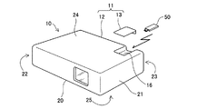
図1および図2を参照して、プロジェクタ10の概略構成について説明する。図1は、第1実施例におけるプロジェクタの外部構成を例示する説明図である。図2は、第1実施例におけるプロジェクタ10に設けられている収容部を例示する説明図である。プロジェクタ10は、取得した画像データに応じて光学像を形成し、形成した光学像を、投射レンズを介して投写面であるスクリーンに投射するプロジェクタである。プロジェクタ10は、画像を形成する画像形成光学系および画像をスクリーンに投射する投射光学系を収容する外装ケース11を備える。
A. First Example A1. Projector configuration:
A schematic configuration of the
外装ケース11は、筐体12と蓋13とを備える。筐体12は、前面20,側面21,22、背面23,上面24および下面25の6つの長方形状の面を有しており、略直方体状に形成されている。筐体12には、プロジェクタ10に投射させるための画像データが格納されているUSBメモリ50の外形全体を収容するための収容部16が設けられている。収容部16は、上面24から背面23に亘って窪み状に形成されている。蓋13は、収容部16に収容されているUSBメモリ50を覆うように、収容部16に装着される。なお、本実施例において、筐体12は、特許請求の範囲における「筐体」に当たり、蓋13は特許請求の範囲おける「被覆部材」にあたり、収容部16は、特許請求の範囲の「収容部」に当たり、USBメモリは特許請求の範囲における「USB機器」に当たる。
The
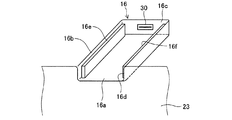
図2を参照して収容部16について説明する。図2は、外装ケース11を背面23から視認したときの、収容部16の周辺部分の拡大図である。収容部16は、それぞれ互いに隣接する側面とほぼ直角に交わる底面16a、側面16b、16cおよび16dを備えており、外装ケース11の内側に向かってU字状に陥没した形状に形成されている。収容部16の側面16cには、USBメモリ50のインタフェース30が設けられている。収容部16は、USBメモリ50の全体が完全に収容可能な大きさおよび形状となるように形成されており、例えば、利用者がUSBメモリ50をインタフェース30に容易に接続できる必要十分な大きさおよび形成に形成されている。第1実施例において、インタフェース30は、特許請求の範囲の「接続手段」に当たる。
The
また、収容部16の側面16b、16dは、収容部16の内側に向けて蓋13を支持するための突状部16e、16fを備える。突状部16e、16fは、蓋13の厚み分だけ、上面24から内側に形成されている。突状部16e、16fは、側面16b、16dから1mm程度突状に形成されていればよい。なお、突状部16e、16fを設けなくても良い。
Further, the side surfaces 16 b and 16 d of the
図3は、第1実施例における蓋13の装着状態を例示する説明図である。図3(a)は、蓋13の装着前の状態を表しており、図3(b)は、蓋13の装着後の状態を表している。図3(a)に示すように、USBメモリ50がインタフェース30に挿入されると、USBメモリ50の外形全体は収容部16内に完全に収容される。このとき、USBメモリ50とプロジェクタ10の画像形成光学系との間の信号制御線が接続される。利用者は、この状態で蓋13を筐体12に装着する。
FIG. 3 is an explanatory view illustrating the mounting state of the
蓋13は、筐体12への装着時、筐体12の外形に沿うように形成されている。すなわち、蓋13は、筐体12の外周面である背面23と上面24に沿うように、ほぼ段差無く筐体12に装着される。「ほぼ段差無く」とは、完全に段差が無い状態だけでなく、製造誤差による微少な段差や、筐体12と蓋13との境界部分に生じる溝による段差を含むことを意味する。
The
具体的には、蓋13は、背面23の切り欠き部分23a(図3(a)に太実線で示す)とほぼ同じ形状に形成されている薄板状の背面部14と、収容部16の頂点16g,16h,16i,16jを結合して形成される平面とほぼ同形状に形成されている薄板状の上面部15を備えており、背面部14と上面部15とが略直角に交わるように形成されている。蓋13をこのように形成することにより、蓋13は、筐体12への装着時に、突状部16e、16fに支持されて、背面部14が切り欠き部分23aに嵌合されるとともに、上面部15が上面24に嵌合される。この結果、筐体12と蓋13により、外周面に段差の無い外装ケース11が構成される。
Specifically, the
A2.機能ブロック:
図4は、第1実施例におけるプロジェクタ10を示す説明図である。プロジェクタ10は、制御部100と、インタフェース30と、光源装置300と、照明光学系310と、画像形成光学系320と、投写光学系350とを有している。光源装置300は、光源ランプ110と図示しない電力供給部を有している。照明光学系310は、レンズやミラーなど種々の光学素子を有している。画像形成光学系320は、レンズやミラーなどの種々の光学素子によって構成された光分離光学系325、液晶ライトバルブ330R、330G、330Bおよびクロスダイクロイックプリズム340を有する。
A2. Function block:
FIG. 4 is an explanatory diagram showing the
制御部100は、光源装置300と、照明光学系310と、画像形成光学系320と、投写光学系350のそれぞれの動作を制御する。例えば光源装置300を制御して光を射出させたり、液晶ライトバルブ330Rのトランジスタの駆動制御を行って画像を形成したりする。制御部100は、インタフェース30に接続されたUSBメモリ50から表示すべき画像を表す画像データGDを取得し、取得した画像データGDに種々の画像処理を施す。そして、種々の画像処理を施した画像処理後の画像データGDに基づいて、画像形成光学系320を制御する。
The
光源装置300は、制御部100からの指示に応じて光源ランプ110に電力を供給する。光源ランプ110は、電力供給を受けて、照射方向Dに向けて光を照射する。照射方向Dは、光軸AXと平行である。なお、図示を省略しているが、光源ランプ110からの光は、平行化レンズを通過して照明光学系310に入射するように構成されている。
The
照明光学系310は、光源装置300からの光の照度を均一化する。また、照明光学系310は、光源装置300からの光の偏光方向を一方向に揃える。この理由は、光源装置300からの光を有効に利用するためである。照度分布と偏光方向とが調整された光は、画像形成光学系320に入射する。
The illumination
画像形成光学系320は、入射光を、赤(R)、緑(G)、青(B)の3つの色光に分離し、制御部100からの指示に基づいて3つの色光を合成する。具体的には、分離された3つの色光は、各色に対応付けられた液晶ライトバルブ330R、330G、330Bによって、それぞれ変調され、クロスダイクロイックプリズム340によって合成される。合成光は、投写光学系350に入射する。
The image forming
投写光学系350は、入射光を、図示しないスクリーンに投写する。これにより、スクリーン上には画像データGDにより表される画像が表示される。
The projection
なお、光源装置300、照明光学系310、画像形成光学系320および投写光学系350のそれぞれの構成には、周知の種々の構成を採用可能である。
Various well-known configurations can be adopted as the configurations of the
以上説明した第1実施例のプロジェクタ10によれば、USBメモリ50の被覆部材としての蓋13は、USBメモリ50がインタフェース30に接続された状態で、USBメモリ50を覆うように筐体12に装着される。従って、USBメモリ50がインタフェース30に接続されている状態で、外部に露出されることを回避できる。よって、USBメモリ50の盗難・紛失を抑制できる。
According to the
また、第1実施例のプロジェクタ10によれば、蓋13および収容部16は、蓋13が筐体12に装着された状態で筐体12の外形に沿うように形成されている。従って、USBメモリ50が接続された状態で、USBメモリ50や筐体12に装着された蓋13が、筐体12の表面から突出しないので、プロジェクタ10の設置や運搬時に、USBメモリ50および蓋13が邪魔になることを抑制できる。
Further, according to the
B.第2実施例:
第2実施例では、プロジェクタの電源プラグの接続/非接続に応じて、筐体12に装着された蓋の取り外しを防止するロック機構を備えるプロジェクタについて説明する。なお、本明細書において、「ロック機構」は特許請求の範囲の「防止手段」に当たる。第2実施例のプロジェクタは、画像形成手段や照明光学系等の内部構成については第1実施例と同様である。
B. Second embodiment:
In the second embodiment, a projector including a lock mechanism that prevents removal of a lid attached to the
B1.プロジェクタ概略構成:
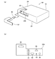
図5は、第2実施例におけるプロジェクタ10aを説明する説明図である。図5(a)は、プロジェクタ10aは、電源プラグ60が差し込まれる電源ソケット61と、第1実施例と同様に、収容部16が形成された筐体12と、収容部16に装着される蓋13aを有している。電源プラグ60は、一端が電源ソケット61に接続され、他端が、商用電源に接続されており、電源ソケット61を介して商用電源からの電力をプロジェクタ10aに供給する。第2実施例では、電源プラグ60がプロジェクタ10aに非接続の状態、すなわち、電源プラグ60が電源ソケット61に差し込まれていない状態のときに、蓋13aの取り外しができないように、プロジェクタ10aの筐体12と蓋13aとに、取り外しを防止するロック機構を設けている。ロック機構は、第2実施例では、ロック受け部26とソレノイド27とから構成されている。
B1. Projector configuration:
FIG. 5 is an explanatory diagram for explaining the projector 10a in the second embodiment. 5A, the projector 10a includes a
電源ソケット61は、電源プラグ60の接続を検出する検出部62を備える。検出部62は、電源ソケット61に設けられており、電源プラグ60が電源ソケット61に形成されると筐体12の内側に押し込まれるように構成されている。プロジェクタ10aは、内部に図示しない二次電池を備えており、検出部62の押下を検出すると、ソレノイドに電流が供給されるように構成されている。例えば、プロジェクタ10aは、検出部62の押下検出によってオン状態となり、ソレノイドに電力を供給するスイッチ回路を備えていてもよい。
The
図6は、第2実施例における蓋13aのロック機構について説明する模式図である。図6(a)〜(d)は、蓋13aの筐体12への装着時のロック機構の動きを、時系列で表している。図6(a)に示すように、蓋13aは、背面部14aと上面部15aとを備えている。背面部14aと上面部15aは、第1実施例の背面部14と上面部15とほぼ同一の構成を有している。ただし、第2実施例の背面部14aは、背面23よりも厚く形成されており、筐体12への装着時に、背面23に接しない部分にロック受け部26が構成されている。ロック受け部26は、窪み状に形成された孔部26aを備える。
FIG. 6 is a schematic diagram for explaining the locking mechanism of the
筐体12は、背面23の内側であって、ロック受け部26に対向する位置にソレノイド27を備えている。ソレノイド27は、可動鉄心28および図示しない内蔵ばね、磁気回路となるフレーム、固定鉄芯および励磁用コイルを備える。可動鉄心28は、ロック受け部26の孔部26aに嵌合する形状に形成されている。ソレノイド27は、電源プラグ60が電源ソケット61に差し込まれている間(以降、本明細書では「接続中」と呼ぶ)、励磁用コイルに電流が供給されるように構成されている。従って、ソレノイド27は、接続中、可動鉄心28が筐体12の内側方向(ソレノイド27の内側方向)に向かって可動鉄心28を引っ張る電磁力が発生するプル型のソレノイドである。
The
可動鉄心28は、電源プラグ60が電源ソケット61に差し込まれていない状態では、図示しない内蔵ばねの付勢力によって、図6(a)に示すように、側面16dから収容部16の内側に突出している。背面部14aに対向する可動鉄心28の部位は、図6(a)に示すように、斜面状に形成されている。これは、背面部14aによる押圧に応じて可動鉄心28を可動させるためである。
When the
図6(b)に示すように、蓋13aが筐体12の上方から収容部16を覆うように装着されはじめると、可動鉄心28は背面部14aに押圧されて、矢印X1に示すように筐体12の内側方向に移動する。筐体12への蓋13aの装着が完了すると、図6(c)に示すように、可動鉄心28は、内蔵ばね29の付勢により矢印X2方向に押され、ロック受け部26の孔部26aに嵌め込まれる。このように、プロジェクタ10aは、電源プラグ60の非接続中に蓋13aが筐体12に装着されると、ロック受け部26にソレノイド27の可動鉄心28が差し込まれたロック状態となる。この結果、非接続中は、筐体12からの蓋13aの取り外しが防止される。
As shown in FIG. 6B, when the
電源ソケット61に電源プラグ60が接続されて検出部62が押圧されると、励磁用コイルに電流が供給される。励磁用コイルに電流が供給されると、ソレノイド27の励磁用コイルに電磁力が発生し、図6(d)に示すように、可動鉄心28が筐体12の内側方向(矢印X1方向)に向かって引っ張られる。この結果、ロック受け部26からソレノイド27の可動鉄心28が抜かれ、ロック状態が解除される。すなわち、第2実施例のプロジェクタ10aは、電源プラグ60が非接続の間(非接続中)は、蓋13aを筐体12から取り外すことができず、接続されると取り外しが可能となる。
When the
以上説明した第2実施例のプロジェクタ10aによれば、蓋13aの筐体12からの取り外しが防止されるので、蓋13aが筐体12に装着されている間は、USBメモリ50を容易に取り外すことができなくなる。従って、USBメモリ50の紛失や盗難を抑制できる。
According to the projector 10a of the second embodiment described above, the
一般的に、非接続時にはプロジェクタ10aは動作しておらず、設置されている場合や運搬中である場合に当たる。従って、第2実施例のプロジェクタ10aによれば、電源非接続時(非接続時)に蓋13aの取り外しが防止されるので、設置された状態でUSBメモリ50の管理者がプロジェクタ10aの近傍に存在しない場合や、運搬時にプロジェクタ10aが乱雑に扱われた場合にも、USBメモリ50の紛失、盗難を抑制できる。
Generally, the projector 10a does not operate when not connected, and corresponds to a case where the projector 10a is installed or is being transported. Therefore, according to the projector 10a of the second embodiment, the
C.第3実施例:
第3実施例では、投写光学系350に含まれる投射レンズのレンズカバーの開閉に応じて、筐体12に装着される蓋の取り外しを防止するロック機構を設けたプロジェクタについて説明する。第3実施例では、レンズカバーが開かれると、筐体12からの蓋の取り外しが防止される。第3実施例のプロジェクタにおいて、画像形成手段や照明光学系等の内部構成については第1実施例と同様である。
C. Third embodiment:
In the third embodiment, a projector provided with a lock mechanism that prevents the lid attached to the
C1.プロジェクタ概略構成:
図7は、第3実施例におけるプロジェクタ10bについて説明する説明図である。図7(a)は、プロジェクタ10bの概略構成を示しており、図7(b)は、蓋13bの取り外しを防止するためのロック機構について模式的に表している。第3実施例において、ロック機構は、接続部材80と、ロックバー90と、貫通孔Hとから構成されている。図7(a)に示すように、プロジェクタ10bは、投射レンズをカバーするための、スライド式に構成されたレンズカバー40を備えている。レンズカバー40は、スライドバー41をスライド溝42に沿って矢印Yのように移動させることにより、スライドバー41の動きに連動して開閉する。なお、第3実施例では、スライドバー41を図面右から左へ移動させることによりレンズカバー40が開き、スライドバー41を図面左から右へ移動させることによりレンズカバー40が閉じるように構成されている。スライドバー41は、レンズカバー40と一体的に構成されている。
C1. Projector configuration:
FIG. 7 is an explanatory diagram for explaining the
図7(b)に示すように、スライドバー41は、レンズカバー40に接合されている。また、蓋13bの上面部15bは、長辺の略中央部分にスライドバー41のスライド方向にほぼ平行に形成された貫通孔Hを有している。そして、第3実施例のプロジェクタ10bには、ロックバー90と、ロックバー90とスライドバー41とを連結する接続部材80とが設けられている。ロックバー90は、貫通孔Hの貫通方向の延長上に設けられており、貫通孔Hに挿抜可能な形状に構成されている。例えば、貫通孔Hが図7(b)に示すように角柱状である場合には、ロックバー90は、貫通孔Hよりも若干小さい角柱状(例えば、長辺に並行に切断した場合の矩形断面の縦横の長さを、0.5mm程度小さい角柱状)に形成されていればよい。角柱状に限らず、円形や三角形など種々の形状を適用可能である。
As shown in FIG. 7B, the
筐体12からの蓋13bの取り外しを防止するロック機構について説明する。図7(b)に示すように、スライドバー41がレンズカバー40の開方向に向けて移動されると、スライドバー41と接続部材80により連結されたロックバー90は、スライドバー41と同方向(レンズカバー40の開方向)に移動する。この結果、ロックバー90は貫通孔Hに挿入され、蓋13bはロック状態となり、筐体12からの蓋13bの取り外しができなくなる。スライドバー41がレンズカバー40の閉方向に向けて移動されると、ロックバー90は貫通孔Hから抜かれロック状態が解除され、蓋13bの取り外しが可能となる。
A lock mechanism for preventing the
以上説明した第3実施例のプロジェクタ10bによれば、レンズカバー40が開いている場合に、蓋13bの筐体12からの取り外しが防止される。一般的に、レンズカバー40が開いているときはプロジェクタ10bが動作中であるので、動作中にUSBメモリ50が取り外されることによる画像データの破壊、USBメモリ50の損傷を抑制できる。
According to the
D.第4実施例:
第4実施例では、USBメモリ50を収容するための収容部16を覆うように筐体12に装着される蓋に、収容部16の内部すなわち、USBメモリ50の接続状態を利用者により視認可能とする確認窓を設けたプロジェクタについて説明する。第4実施例のプロジェクタにおいて、画像形成手段や照明光学系等の内部構成については第1実施例と同様である。
D. Fourth embodiment:
In the fourth embodiment, a user can visually recognize the inside of the
D1.プロジェクタ概略構成:
図8は、プロジェクタ10cについて説明する説明図である。図8(a)は、プロジェクタ10cの概略構成を示しており、図8(c)は、蓋13cに形成された確認窓から視認される収容部16内部の状態を示している。
D1. Projector configuration:
FIG. 8 is an explanatory diagram for explaining the
図8(a)に示すように、第4実施例の蓋13cは、収容部16の内部を視認可能に構成された確認窓400を備える。確認窓400は、蓋13cの上面部15cに略円形に形成された貫通穴内に、ガラスなどの透明な樹脂が嵌め込まれることにより構成されている。本実施例において、確認窓400は、特許請求の範囲における「確認手段」に当たる。
As shown to Fig.8 (a), the
例えば、図8(b)に示すように、インタフェース30にUSBメモリ50が接続/非接続されている場合、利用者は、図8(b)に斜線ハッチングで示すように、確認窓400を介してUSBメモリ50の上面31を視認できる。すなわち、利用者は、確認窓400を見ることにより、USBメモリ50が接続されているかを確認できる。
For example, as shown in FIG. 8B, when the
以上説明した第4実施例のプロジェクタ10cによれば、蓋13cは、USBメモリ50の接続状態を視認可能に構成された確認窓400を備えている。従って、蓋13cを筐体12に装着した状態で、USBメモリ50が接続されているか否か等USBメモリ50の状態を利用者が視認することができる。よって、利用者の利便性を向上できる。
According to the
E.第5実施例:
第5実施例では、収容部と、プロジェクタの部材の保守・点検等に用いられる開口部とを共に覆うように形成されている蓋を備えるプロジェクタについて説明する。ここで、「プロジェクタの部材」とは、例えば、交換可能な光源ランプや着脱可能なフィルターなどを含む。第5実施例のプロジェクタにおいて、画像形成手段や照明光学系等の内部構成については第1実施例と同様である。
E. Example 5:
In the fifth embodiment, a projector including a lid formed so as to cover both a housing portion and an opening portion used for maintenance and inspection of a member of the projector will be described. Here, the “projector member” includes, for example, a replaceable light source lamp and a detachable filter. In the projector of the fifth embodiment, the internal configuration of the image forming means and the illumination optical system is the same as that of the first embodiment.
E1.プロジェクタ概略構成:
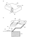
図9は、第5実施例におけるプロジェクタ10dの構成について説明する説明図である。プロジェクタ10dは、外装ケース11dとして、筐体12dと蓋13dとを備える。筐体12dは略矩形上に形成されており、筐体12dの一つの隅部には、内側に陥没した収容部216を備える。収容部216には、USBメモリ50と共に光源ランプ110が収容されている。プロジェクタ10dは、光源ランプ110を交換可能に構成されており、収容部216は、光源ランプ110を交換するための開口部を兼ねている。第5実施例において、収容部216は、特許請求の範囲における「収容部」および「開口部」に当たる。
E1. Projector configuration:
FIG. 9 is an explanatory diagram illustrating the configuration of the
蓋13dは、上述の第1実施例において説明した蓋13と同様に、筐体12dの背面23と上面24とにほぼ段差無く筐体12に装着されるように形成されている。すなわち、収容部216を覆うことにより、蓋13dは、USBメモリ50だけでなく、光源ランプ110をも併せて被覆するように構成されている。
Similarly to the
以上説明した第5実施例のプロジェクタ10dによれば、蓋13dは、USBメモリ50とプロジェクタ10dの他の部材である光源ランプ110とを共に被覆するように形成される。従って、プロジェクタ10dの部材の数の増大を抑制できる。
According to the
F.第6実施例:
第6実施例では、USBメモリ50を覆う蓋の筐体12からの取り外しに伴って、USBメモリ50が蓋とともにインタフェース30から取り外されるように構成されたプロジェクタについて説明する。第6実施例のプロジェクタにおいて、画像形成手段や照明光学系等の内部構成については第1実施例と同様である。
F. Example 6:
In the sixth embodiment, a projector configured so that the
F1.プロジェクタ概略構成:
図10は、第6実施例におけるプロジェクタ10eの概略構成について説明する説明図である。図11は、第6実施例における蓋13eの構成について説明する説明図である。プロジェクタ10eは、筐体12および蓋13eを備えている。筐体12は、第1実施例と同様に、内側にUSBメモリ50接続用のインタフェース30を備えている。
F1. Projector configuration:
FIG. 10 is an explanatory diagram illustrating a schematic configuration of the
第6実施例では、図10に示すように、筐体12に装着されている蓋13eの取り外し時に、USBメモリ50も同時にインタフェース30から取り外されるよう構成されている。
In the sixth embodiment, as shown in FIG. 10, the
図11(a)に示すように、蓋13eは、背面部14eと、上面部15eと、係合部70を備える。係合部70は、上面部15eにおける背面部14eとは逆側の端部に設けられた薄板状の部材であり、筐体12に装着した状態でUSBメモリ50のコネクタ51に対応する位置に形成された切り欠き部71と、蓋13eの取り外し時にUSBメモリ50に当接する当接部72とから構成される。切り欠き部71の幅Dは、USBメモリ50のコネクタ51の幅dに一致もしくは幅dよりも若干(例えば、1mm程度)大きく形成されている。なお、USBメモリ50のコネクタ51の幅dは、予め規格により規定されている。本実施例において、係合部70は、特許請求の範囲における「係合部材」に当たる。
As shown in FIG. 11A, the
蓋13eは、USBメモリ50がインタフェース30に接続されている状態で、図11(b)に示すように、収容部16の上方(上面24側)から筐体12に装着される。USBメモリ50のコネクタ51は、インタフェース30に接続された状態で、本体52とインタフェース30が設けられている側面16cとの間に数ミリ程度の隙間が生じており、蓋13eの筐体12への装着に伴い、係合部70が本体52と側面16cとの隙間に挿入される。この結果、図11(c)に示すように、コネクタ51は切り欠き部71に嵌合する。
The
蓋13eは、水平方向(USBメモリ50の挿抜方向)に引き抜かれることにより、筐体12から取り外される。このとき、当接部72がUSBメモリ50の本体52に当接する。言い換えれば、USBメモリ50が係合部70に係合した(引っ掛かった)状態となる。よって、蓋13eを引き抜いて筐体12から取り外すと、蓋13eの係合部70に引っ掛かっているUSBメモリ50も蓋13eと共に水平方向に引っ張られる。この結果、USBメモリ50はインタフェース30から引き抜かれる。
The
以上説明した第6実施例のプロジェクタ10eによれば、蓋13eは、筐体12からの蓋13eの取り外しに伴って、USBメモリ50がインタフェース30から取り外されるように構成された係合部70を備えている。すなわち、USBメモリ50は、蓋13eの筐体12からの取り外し時に、蓋13eと共にインタフェース30から取り外される。従って、利用者は、蓋13eとUSBメモリ50とをまとめて取り外すことができるため、利用者の手間を省略できる。よって、利用者の利便性を向上できる。
According to the
G.第7実施例:
第7実施例では、外部記憶装置やUSBメモリ50以外の記憶媒体等を接続するための接続インタフェースを、USBメモリ50とともに覆う蓋13fを備えるプロジェクタ10fについて説明する。第7実施例のプロジェクタにおいて、画像形成手段や照明光学系等の内部構成については第1実施例と同様である。
G. Seventh embodiment:
In the seventh embodiment, a
G1.プロジェクタ概略構成:
図12は、第7実施例におけるプロジェクタ10fを説明する説明図である。図12(a)は、プロジェクタ10fの概略構成を示す斜視図であり、図12(b)は、外部記憶装置やUSBメモリ50以外の記憶媒体等を接続するための接続インタフェース群を、プロジェクタ10fの背面23側からみた平面図である。第7実施例において、収容部226には、USBメモリ50のインタフェース30と、各種機器の接続インタフェースが設けられている。
G1. Projector configuration:
FIG. 12 is an explanatory diagram illustrating the
各種インタフェースとしては、第7実施例では、図12(b)に示すように、USBメモリ50接続用のインタフェース30の他に、DVDプレーヤーやゲーム機器を接続するためのコンポーネント入力端子91,パソコン等をシリアル接続するための端子であるコントロール端子92(例えば、RS−232C)、ビデオを接続するためのビデオ端子93,ビデオカメラ等を接続するためのSビデオ端子94およびパソコンと接続するためのPC/コンポーネント端子95(VGAコネクタ用)を備える。
As various interfaces, in the seventh embodiment, as shown in FIG. 12B, in addition to the
蓋13fは、筐体12に装着された状態で、インタフェース30に接続されたUSBメモリ50だけでなく、各種端子91〜95も被覆するように形成されている。
The
以上説明した第7実施例のプロジェクタ10fによれば、USBメモリ50と各種端子91〜95とをまとめて被覆するように蓋13fが形成されている。従って、USBメモリ50から画像データを読み込んでスクリーンに画像を表示する際に、インタフェース30以外の各種端子91〜95への埃等の付着を抑制できる。よって、プロジェクタ10fの故障を抑制できる。
According to the
H.第8実施例:
第8実施例では、USBメモリ50がインタフェース30に接続された状態で、USBメモリ50内に記憶されている情報(画像データGD)をホストコンピュータから編集可能に構成したプロジェクションシステムについて説明する。
H. Example 8:
In the eighth embodiment, a projection system will be described in which information (image data GD) stored in the
H1.プロジェクタ概略構成:
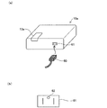
図13は、第8実施例のプロジェクションシステム1000について説明する説明図である。プロジェクションシステム1000は、第1実施例において説明したプロジェクタ10と、ホストコンピュータPCを備える。第8実施例では、USBメモリ50とホストコンピュータPCは、相互に無線通信可能となるように無線LANや赤外線通信などの無線通信手段を備えている。ホストコンピュータPCには、USBメモリ50に記憶されている画像データGDを編集可能なアプリケーションソフトが組み込まれている。
H1. Projector configuration:
FIG. 13 is an explanatory diagram for explaining the
第8実施例のUSBメモリ50は、インタフェース30を介してホストコンピュータPCと通信するための電力をプロジェクタ10から取得している。
The
ホストコンピュータPCは、USBメモリ50を外部記憶装置として認識する。利用者は、アプリケーションソフトを用いてUSBメモリ50内の画像データGDを編集することができる。
The host computer PC recognizes the
以上説明した第8実施例のプロジェクションシステム1000によれば、USBメモリ50をプロジェクタ10に接続した状態で、USBメモリ50に記憶されている画像データGDを編集できる。従って、画像データGDの編集を所望する場合に、USBメモリ50を、その都度、プロジェクタ10から取り外す必要が無くなる。よって、USBメモリ50の紛失、画像データの盗難を抑制できるとともに、利用者の利便性を向上できる。
According to the
なお、プロジェクタ10は、第2実施例のプロジェクタ10a〜プロジェクタ10fを適用してもよい。例えば、第2実施例、第3実施例のように、USBメモリ50の取り外しが禁止(防止)されるロック機構を備える場合には、ロックを外すことなく画像データGDの編集を行うことができ、好適である。
The
I.変形例:
(1)上述の各実施例の蓋もしくは筐体12に、更に、USBメモリ50の動作状態を視認可能なインジケータを設けても良い。図14は、変形例におけるプロジェクタ10gの概略構成について説明する説明図である。図14(a)は、蓋にインジケータを設けた例を示しており、図14(b)は、筐体12にインジケータを設けた例を示している。変形例のプロジェクタにおいて、画像形成手段や照明光学系等の内部構成については第1実施例と同様である。
I. Variation:
(1) You may provide the indicator which can visually recognize the operation state of the
図14(a)に示すように、変形例のプロジェクタ10gは、蓋13gに、インジケータ500を有する。また、図14(b)に示すように、変形例のプロジェクタ10hは、筐体12にインジケータ501を有する。インジケータ500、501は、例えば、エルイーディー(LED)等の発光素子を用いて構成されている。プロジェクタ10gの制御部(図示省略)は、USBメモリ50がインタフェース30に接続されている場合や、制御部がUSBメモリにアクセスしている場合等、種々の任意のタイミングでインジケータ500、501を表示させてもよい。インジケータ500、501と制御部とは、有線もしくは無線により接続されている。インジケータ500、501は、特許請求の範囲の「確認手段」の一態様に含まれる。
As shown in FIG. 14A, the
変形例のプロジェクタによれば、蓋が装着されUSBメモリ50が外部から視認できない状態であっても、USBメモリ50の動作状態がインジケータ500、501により外部から一目でわかるため、利用者の利便性の向上を図ることができる。
According to the projector of the modified example, even when the lid is attached and the
(2)第2実施例および第3実施例では、ロックバー90を孔部26aもしくは貫通孔Hに挿入することにより、蓋がロック状態となるようにロック機構を構成しているが、ロック機構は、第2実施例および第3実施例に記載した態様に限られるものではなく、蓋等の部品を他の部品から取り外すことを防止する周知の種々の構成を適用可能である。例えば、一般的なシリンダー状や南京錠を設けても良い。また、例えば、ロック機構に、指紋認証や静脈認証を併せて設けても良い。
(2) In the second and third embodiments, the lock mechanism is configured so that the lid is locked by inserting the
(3)第3実施例では、スライドバー41の動作に伴ってロック機構が動作するように構成されているが、例えば、スライドバー41の開閉を検知するセンサを設け、センサの検出結果に応じて、ロック機構を動作するように構成してもよい。こうすれば、接続部材80を設ける必要がないため、接続部材80の損傷によるロック機構の動作不良を回避できる。また、第2実施例においても、同様に、電源プラグ60の接続を検出するセンサを設け、センサの検出結果に応じてロック機構を動作するように構成してもよい。
(3) In the third embodiment, the lock mechanism is configured to operate in accordance with the operation of the
(4)第2実施例では、電源プラグ60がプロジェクタ10aに接続されていない状態、すなわち、電源プラグ60が電源ソケット61に差し込まれていない状態のときに、蓋13aの取り外しができないように、プロジェクタの筐体12と蓋13aとに、取り外しを防止するロック機構を設けているが、例えば、第2実施例の構成とは逆に、電源プラグがプロジェクタに接続され、プロジェクタが稼働している状態、すなわち、電源プラグ60が電源ソケット61に差し込まれている状態のときに、蓋13aの取り外しができないように、ロック機構を構成してもよい。この場合、ロック機構に含まれるソレノイドをプッシュ型に構成すればよい。こうすれば、接続中は、可動鉄心28がロック受け部26に挿入されているため、蓋13aはロック状態となり、蓋13aの取り外しが防止される。従って、動作中など電源が供給されている状態で、誤ってUSBメモリ50が取り外されることを抑制できる。よって、プロジェクタ10aの動作中にUSBメモリ50が取り外されることによる画像データの破壊、USB機器の損傷を抑制できる。なお、ここで「稼働している状態」とは、プロジェクタの電源が投入され画像表示処理を行っている場合だけでなく、単に、電源プラグ60が電源ソケット61に接続されている状態をも含むことを意味する。
(4) In the second embodiment, the
(5)第3実施例では、レンズカバー40が開かれると、筐体12からの蓋13bの取り外しが防止されるように構成されているが、例えば、レンズカバー40が閉じられると、筐体12からの蓋13bの取り外しが防止されるように構成してもよい。この場合、例えば、第3実施例とは逆に、ロックバー90が、蓋13bの図面左側から貫通孔Hに挿入されるように構成すればよい。レンズカバー40は、スライドバー41が図7の図面左から右に移動されることにより閉じるように構成されているので、本変形例のように構成することにより、レンズカバー40が閉じられると、蓋13bはロック状態となり、筐体12からの蓋13bの取り外しが防止される。一般的に、レンズカバー40が閉じられている場合、プロジェクタ10bは動作していない状態で設置されている場合や運搬中などである。従って、設置された状態でUSBメモリ50の管理者がプロジェクタ10bの近傍に存在しない場合や、運搬時にプロジェクタ10bが乱雑に扱われた場合にも、USBメモリ50の紛失、盗難を抑制できる。
(5) In the third embodiment, when the
(6)上述の各実施例では、USBメモリ50を被覆する被覆部材として取り外し可能な蓋が用いられているが、被覆部材としては蓋に限られない。例えば、筐体12に取り付けられた開閉可能な蓋や、USBメモリ50の全体を覆うように設けられるカバーなど種々の態様を適用可能である。
(6) In each of the embodiments described above, a removable cover is used as a covering member that covers the
(7)上述の各実施例では、USBメモリ50の被覆部材としての蓋は、筐体12の外形に沿うように、すなわち、筐体12の外周面と段差がほぼ生じないように形成されているが、例えば、USBメモリ50の被覆部材が、筐体12の外形(外周面)から突出するように形成されていてもよい。例えば、インタフェース30に接続された状態でUSBメモリ50が筐体12から突出しており、被覆部材としてUSBメモリ50の外形(少なくとも筐体12から突出している部分)を覆うカバー状の部材を用いてもよい。この場合、どの部分にUSBメモリ50が設置されているか明確にわかるという利点がある。
(7) In each of the above-described embodiments, the lid as the covering member of the
(8)上述の第1実施例、第4実施例〜第7実施例では、蓋13を筐体12から取り外し防止とするロック機構は備えられていないが、第1実施例、第4実施例〜第7実施例のプロジェクタにロック機構を備えてもよいことは言うまでもない。
(8) In the first embodiment, the fourth embodiment to the seventh embodiment described above, the lock mechanism for preventing the
(9)上述の第4実施例では、蓋13cの確認窓400には、ガラス等の樹脂が嵌め込まれているが、例えば、ガラス等の樹脂が嵌め込まれておらず、単なる貫通孔であっても良い。また、例えば、確認窓400を開閉可能な構成としてもよい。収容部16の内部が視認できる態様であれば、確認窓400は種々の形状、構成を適用可能である。
(9) In the above-described fourth embodiment, resin such as glass is fitted in the
(10)上述の第5実施例では、光源ランプ110とUSBメモリ50とをともに被覆するように蓋13dが構成されているが、例えば、フィルターなど他の部材とUSBメモリ50とをともに被覆するように蓋を構成してもよい。また、1以上の他の部材とUSBメモリ50とをまとめて被覆するように蓋を構成してもよい。
(10) In the fifth embodiment described above, the
(11)上述の第8実施例では、USBメモリ50とホストコンピュータPCとが、直接、無線通信を行うこととしているが、例えば、プロジェクタ10を介してホストコンピュータPCとUSBメモリ50とが通信を行うように構成してもよい。この場合、プロジェクタ10とホストコンピュータPCとの間は有線/無線いずれの通信態様でもよい。また、プロジェクタと携帯電話とが赤外線等による通信を行い、画像データの編集を行うことができるように構成してもよい。
(11) In the eighth embodiment described above, the
以上、本発明の種々の実施例について説明したが、本発明はこれらの実施例に限定されず、その趣旨を逸脱しない範囲で種々の構成をとることができる。 As mentioned above, although the various Example of this invention was described, this invention is not limited to these Examples, A various structure can be taken in the range which does not deviate from the meaning.
10、10a、10b、10c、10d、10e、10f、10g、10h…プロジェクタ、11、11d…外装ケース、12、12d…筐体、13、13a、13b、13c、13d、13e、13f、13g…蓋、14、14a、14e…背面部、15a、15b、15c、15d、15e…上面部、16、216,226…収容部、16a…底面、16b…側面、16c…側面、16d…側面、16e…突状部、16g、16h、16i、16j…頂点、20…前面、21…側面、23…背面、23a…切り欠き部分、24…上面、25…下面、26…ロック受け部、26a…孔部、27…ソレノイド、28…可動鉄心、30…インタフェース、31…上面、40…レンズカバー、41…スライドバー、42…スライド溝、51…コネクタ、52…本体、60…電源プラグ、61…電源ソケット、70…係合部、71…切り欠き部、72…当接部、80…接続部材、90…ロックバー、91…コンポーネント入力端子、92…コントロール端子、93…ビデオ端子、94…Sビデオ端子、95…PC/コンポーネント端子、100…制御部、110…光源ランプ、300…光源装置、310…照明光学系、320…画像形成光学系、325…光分離光学系、330R、330G、330B…液晶ライトバルブ、340…クロスダイクロイックプリズム、350…投写光学系、400…確認窓
10, 10a, 10b, 10c, 10d, 10e, 10f, 10g, 10h ... projector, 11, 11d ... exterior case, 12, 12d ... casing, 13, 13a, 13b, 13c, 13d, 13e, 13f, 13g ...
Claims (10)
筐体と、
前記筐体に設けられ、前記画像データを記憶するユニバーサルシリアルバス(Universal Serial Bus:USB)機器を接続するための接続部と、
前記USB機器が前記接続部に接続された状態で前記USB機器を覆うように、前記筐体に装着される被覆部材と、を備えるプロジェクタ。 A projector,
A housing,
A connection unit for connecting a universal serial bus (USB) device provided in the housing and storing the image data;
And a covering member attached to the casing so as to cover the USB device in a state where the USB device is connected to the connection unit.
前記接続部を有し、前記USB機器を収容する収容部を備えており、
前記被覆部材は、前記収容部に装着されるとともに、前記収容部に装着された状態で前記筐体の外形に沿うように形成されている、プロジェクタ。 The projector according to claim 1, further comprising:
Having the connecting portion and having a housing portion for housing the USB device;
The said covering member is a projector with which it mounts | wears with the said accommodating part, and is formed so that the external shape of the said housing | casing may be followed in the state with which the said accommodating part was mounted | worn.
前記プロジェクタの保守もしくは点検に使用される開口部を備え、
前記被覆部材は、前記収容部と前記開口部とを共に覆うように形成されている、プロジェクタ。 The projector according to claim 1 or 2, further comprising:
With an opening used for maintenance or inspection of the projector,
The projector is a projector formed so as to cover both the housing portion and the opening.
前記USB機器が前記接続部に接続された状態で、前記被覆部材が前記筐体から取り外されることを防止する防止手段を備える、プロジェクタ。 The projector according to any one of claims 1 to 3, further comprising:
A projector comprising prevention means for preventing the covering member from being removed from the housing in a state where the USB device is connected to the connection portion.
前記プロジェクタは、電源プラグを接続するためのソケットを備えており、
前記防止手段は、前記ソケットに前記電源プラグが接続されている場合、前記被覆部材が前記筐体から取り外されることを防止する、プロジェクタ。 The projector according to claim 4, wherein
The projector includes a socket for connecting a power plug,
The prevention means prevents the covering member from being removed from the casing when the power plug is connected to the socket.
前記プロジェクタは、電源プラグを接続するためのソケットを備えており、
前記防止手段は、前記ソケットに前記電源プラグが接続されていない場合、前記被覆部材が前記筐体から取り外されることを防止する、プロジェクタ。 The projector according to claim 4, wherein
The projector includes a socket for connecting a power plug,
The prevention means prevents the covering member from being removed from the casing when the power plug is not connected to the socket.
前記プロジェクタは、画像を投射表示するための投射レンズを備えており、
前記筐体は、前記投射レンズを保護するためのレンズカバーを備えており、
前記防止手段は、前記レンズカバーが開いている場合に、前記被覆部材が前記筐体から取り外されることを防止する、プロジェクタ。 The projector according to claim 4, wherein
The projector includes a projection lens for projecting and displaying an image,
The housing includes a lens cover for protecting the projection lens,
The said prevention means is a projector which prevents that the said coating | coated member is removed from the said housing | casing, when the said lens cover is open.
前記プロジェクタは、画像を投射表示するための投射レンズを備えており、
前記筐体は、前記投射レンズを保護するための開閉式のレンズカバーを備えており、
前記防止手段は、前記レンズカバーが閉じている場合に、前記被覆部材が前記筐体から取り外されることを防止する、プロジェクタ。 The projector according to claim 4, wherein
The projector includes a projection lens for projecting and displaying an image,
The housing includes an openable lens cover for protecting the projection lens,
The prevention means prevents the covering member from being removed from the casing when the lens cover is closed.
前記被覆部材および前記筐体の少なくとも一方は、前記USB機器の接続状態が視認可能となるように構成された確認手段を備える、プロジェクタ。 A projector according to any one of claims 1 to 8,
At least one of the covering member and the housing includes a confirmation unit configured to make a connection state of the USB device visible.
前記被覆部材は、前記USB機器に係合する係合部材であって、前記被覆部材の筐体からの取り外しに伴って、前記USB機器が前記接続部から取り外されるように構成された係合部材を備える、プロジェクタ。 A projector according to any one of claims 1 to 9,
The covering member is an engaging member that engages with the USB device, and is configured such that the USB device is detached from the connection portion when the covering member is detached from the housing. A projector comprising:
Priority Applications (1)
| Application Number | Priority Date | Filing Date | Title |
|---|---|---|---|
| JP2008219461A JP2010055363A (en) | 2008-08-28 | 2008-08-28 | Projector |
Applications Claiming Priority (1)
| Application Number | Priority Date | Filing Date | Title |
|---|---|---|---|
| JP2008219461A JP2010055363A (en) | 2008-08-28 | 2008-08-28 | Projector |
Publications (2)
| Publication Number | Publication Date |
|---|---|
| JP2010055363A true JP2010055363A (en) | 2010-03-11 |
| JP2010055363A5 JP2010055363A5 (en) | 2011-09-29 |
Family
ID=42071213
Family Applications (1)
| Application Number | Title | Priority Date | Filing Date |
|---|---|---|---|
| JP2008219461A Withdrawn JP2010055363A (en) | 2008-08-28 | 2008-08-28 | Projector |
Country Status (1)
| Country | Link |
|---|---|
| JP (1) | JP2010055363A (en) |
Cited By (2)
| Publication number | Priority date | Publication date | Assignee | Title |
|---|---|---|---|---|
| JP2012118366A (en) * | 2010-12-02 | 2012-06-21 | Seiko Epson Corp | Projector |
| CN105229873A (en) * | 2013-04-25 | 2016-01-06 | 三菱电机株式会社 | Socket protection cover and electronic equipment |
Citations (4)
| Publication number | Priority date | Publication date | Assignee | Title |
|---|---|---|---|---|
| JP2001266993A (en) * | 2000-03-24 | 2001-09-28 | Nec Gumma Ltd | Information processor |
| JP2004207400A (en) * | 2002-12-24 | 2004-07-22 | Seiko Epson Corp | Cover for electronic equipment housing and projector |
| JP2004214973A (en) * | 2002-12-27 | 2004-07-29 | Olympus Corp | Recording medium housing apparatus and digital camera |
| US20070070308A1 (en) * | 2005-09-23 | 2007-03-29 | Topseed Technology Corp. | Projector having built-in portable universal serial bus on the go |
-
2008
- 2008-08-28 JP JP2008219461A patent/JP2010055363A/en not_active Withdrawn
Patent Citations (4)
| Publication number | Priority date | Publication date | Assignee | Title |
|---|---|---|---|---|
| JP2001266993A (en) * | 2000-03-24 | 2001-09-28 | Nec Gumma Ltd | Information processor |
| JP2004207400A (en) * | 2002-12-24 | 2004-07-22 | Seiko Epson Corp | Cover for electronic equipment housing and projector |
| JP2004214973A (en) * | 2002-12-27 | 2004-07-29 | Olympus Corp | Recording medium housing apparatus and digital camera |
| US20070070308A1 (en) * | 2005-09-23 | 2007-03-29 | Topseed Technology Corp. | Projector having built-in portable universal serial bus on the go |
Cited By (3)
| Publication number | Priority date | Publication date | Assignee | Title |
|---|---|---|---|---|
| JP2012118366A (en) * | 2010-12-02 | 2012-06-21 | Seiko Epson Corp | Projector |
| CN105229873A (en) * | 2013-04-25 | 2016-01-06 | 三菱电机株式会社 | Socket protection cover and electronic equipment |
| US9627805B2 (en) | 2013-04-25 | 2017-04-18 | Mitsubishi Electric Corporation | Receptacle protection cover and electronic device |
Similar Documents
| Publication | Publication Date | Title |
|---|---|---|
| JP2006227413A (en) | Projection-type display apparatus | |
| EP3719570A1 (en) | Projector | |
| JP5573240B2 (en) | Projector and image projection method using projector | |
| WO2014156228A1 (en) | Drive recorder | |
| US20090256673A1 (en) | Image acquisition system and method of authenticating image acquisition device in the image acquisition system | |
| JP2010055363A (en) | Projector | |
| JP2002344848A (en) | Lens protection device for projector | |
| JP2005134575A (en) | Picture display projector | |
| JP6069942B2 (en) | Projector and projector control method | |
| US20140085272A1 (en) | Projector system and control method for the projector system | |
| JP2005085831A (en) | Cabinet for electronic apparatus, and projector equipped therewith | |
| JP2008292656A (en) | Projector | |
| JP2010122281A (en) | Projector | |
| JP2008256945A (en) | Projection type display device | |
| JP2009217132A (en) | Image display device | |
| JP2005192095A (en) | Electronic apparatus | |
| JP6056204B2 (en) | Projector and projector control method | |
| JP2013228532A (en) | Projector system and control method for the same | |
| JP2012093605A (en) | Projection type display device and control method thereof | |
| JP5206345B2 (en) | projector | |
| JP3121046U (en) | projector | |
| JP4334238B2 (en) | Light source device for projection display device and projection display device | |
| JP5176744B2 (en) | projector | |
| JP2009169088A (en) | Attaching mechanism for filter device | |
| JP2010217255A (en) | Projector |
Legal Events
| Date | Code | Title | Description |
|---|---|---|---|
| A521 | Written amendment |
Free format text: JAPANESE INTERMEDIATE CODE: A523 Effective date: 20110812 |
|
| A621 | Written request for application examination |
Free format text: JAPANESE INTERMEDIATE CODE: A621 Effective date: 20110812 |
|
| A977 | Report on retrieval |
Free format text: JAPANESE INTERMEDIATE CODE: A971007 Effective date: 20130208 |
|
| A131 | Notification of reasons for refusal |
Free format text: JAPANESE INTERMEDIATE CODE: A131 Effective date: 20130219 |
|
| A761 | Written withdrawal of application |
Free format text: JAPANESE INTERMEDIATE CODE: A761 Effective date: 20130222 |