JP6069942B2 - Projector and projector control method - Google Patents
Projector and projector control method Download PDFInfo
- Publication number
- JP6069942B2 JP6069942B2 JP2012176775A JP2012176775A JP6069942B2 JP 6069942 B2 JP6069942 B2 JP 6069942B2 JP 2012176775 A JP2012176775 A JP 2012176775A JP 2012176775 A JP2012176775 A JP 2012176775A JP 6069942 B2 JP6069942 B2 JP 6069942B2
- Authority
- JP
- Japan
- Prior art keywords
- shutter
- projector
- image
- power
- projection
- Prior art date
- Legal status (The legal status is an assumption and is not a legal conclusion. Google has not performed a legal analysis and makes no representation as to the accuracy of the status listed.)
- Expired - Fee Related
Links
Images


Classifications
-
- G—PHYSICS
- G03—PHOTOGRAPHY; CINEMATOGRAPHY; ANALOGOUS TECHNIQUES USING WAVES OTHER THAN OPTICAL WAVES; ELECTROGRAPHY; HOLOGRAPHY
- G03B—APPARATUS OR ARRANGEMENTS FOR TAKING PHOTOGRAPHS OR FOR PROJECTING OR VIEWING THEM; APPARATUS OR ARRANGEMENTS EMPLOYING ANALOGOUS TECHNIQUES USING WAVES OTHER THAN OPTICAL WAVES; ACCESSORIES THEREFOR
- G03B21/00—Projectors or projection-type viewers; Accessories therefor
- G03B21/14—Details
- G03B21/142—Adjusting of projection optics
-
- G—PHYSICS
- G03—PHOTOGRAPHY; CINEMATOGRAPHY; ANALOGOUS TECHNIQUES USING WAVES OTHER THAN OPTICAL WAVES; ELECTROGRAPHY; HOLOGRAPHY
- G03B—APPARATUS OR ARRANGEMENTS FOR TAKING PHOTOGRAPHS OR FOR PROJECTING OR VIEWING THEM; APPARATUS OR ARRANGEMENTS EMPLOYING ANALOGOUS TECHNIQUES USING WAVES OTHER THAN OPTICAL WAVES; ACCESSORIES THEREFOR
- G03B21/00—Projectors or projection-type viewers; Accessories therefor
- G03B21/14—Details
- G03B21/145—Housing details, e.g. position adjustments thereof
-
- G—PHYSICS
- G03—PHOTOGRAPHY; CINEMATOGRAPHY; ANALOGOUS TECHNIQUES USING WAVES OTHER THAN OPTICAL WAVES; ELECTROGRAPHY; HOLOGRAPHY
- G03B—APPARATUS OR ARRANGEMENTS FOR TAKING PHOTOGRAPHS OR FOR PROJECTING OR VIEWING THEM; APPARATUS OR ARRANGEMENTS EMPLOYING ANALOGOUS TECHNIQUES USING WAVES OTHER THAN OPTICAL WAVES; ACCESSORIES THEREFOR
- G03B21/00—Projectors or projection-type viewers; Accessories therefor
- G03B21/14—Details
- G03B21/20—Lamp housings
- G03B21/2086—Security or safety means in lamp houses
Description
本発明は、プロジェクター、及びプロジェクターの制御方法に関する。 The present invention relates to a projector and a projector control method.
画像を投写するプロジェクターには、投写レンズを保護する、または画像の投写を一時的に中断する(画像ミュート機能という)ために投写光を遮断する目的で、筐体の投写レンズ用開口部を閉鎖可能なスライド式レンズシャッターを搭載したものがある。しかし、使用者が、使用後にレンズシャッターを閉鎖するのを忘れ、そのまま持ち運んでしまう虞があった。 For projectors that project images, the projector's projection lens opening is closed to protect the projection lens or to block projection light to temporarily interrupt image projection (referred to as an image mute function). Some are equipped with possible slide-type lens shutters. However, there is a possibility that the user forgets to close the lens shutter after use and carries it as it is.
下記に示す特許文献1には、レンズシャッターの閉鎖に連動してプロジェクターの電源をオフするプロジェクターが開示されている。このようなプロジェクターによれば、レンズシャッターを閉じればすぐに電源をオフするのでレンズシャッターを閉め忘れたまま持ち運ぶのを防止することができる。
しかしながら、特許文献1のプロジェクターでは、画像の投写を一時的に中断する画像ミュート機能と、電源オフ時におけるレンズシャッターの閉め忘れの防止を両立することはできなかった。また、レンズシャッターの開閉とプロジェクターの電源オン・オフを連動させた場合、誤ってレンズシャッターを開閉しただけでプロジェクターの電源がオン・オフしてしまうという問題があった。
However, the projector of
本発明は、上述の課題の少なくとも一部を解決するためになされたものであり、以下の形態または適用例として実現することが可能である。 SUMMARY An advantage of some aspects of the invention is to solve at least a part of the problems described above, and the invention can be implemented as the following forms or application examples.
[適用例1]本適用例に係るプロジェクターは、光源から射出された光を画像情報に応じて変調して投写面に投写する画像投写手段と、前記画像投写手段を収容する筐体と、を備えたプロジェクターであって、前記筐体に設けられ、前記画像投写手段からの投写光が通過する開口部と、前記開口部を開閉可能なシャッターと、前記シャッターの位置を検出するシャッター位置検出手段と、前記シャッター位置検出手段の検出結果に基づき、前記シャッターが所定のオフ位置で所定時間保持された場合に、前記プロジェクターの電源をオフする制御手段と、を備えたことを特徴とする。 Application Example 1 A projector according to this application example includes: an image projection unit that modulates light emitted from a light source according to image information and projects the light onto a projection plane; and a housing that houses the image projection unit. A projector provided in the housing, through which the projection light from the image projection unit passes, a shutter that can open and close the opening, and a shutter position detection unit that detects the position of the shutter And control means for turning off the power of the projector when the shutter is held at a predetermined off position for a predetermined time based on the detection result of the shutter position detection means.
本適用例によれば、開口部を開閉可能なシャッターを所定のオフ位置で所定時間保持することでプロジェクターの電源をオフするので、誤ってシャッターをオフ位置に移動させた場合でも、シャッターを所定時間内に他の位置に移動させれば電源オフ操作を取り消すことが可能となる。 According to this application example, the projector is turned off by holding the shutter that can open and close the opening at a predetermined off position for a predetermined time. Therefore, even if the shutter is accidentally moved to the off position, the shutter is not If it is moved to another position within the time, the power-off operation can be canceled.
[適用例2]上記適用例に記載のプロジェクターにおいて、前記制御手段は、前記シャッター位置検出手段の検出結果に基づき、前記シャッターが所定のオン位置で所定時間保持された場合に、前記プロジェクターの電源をオンする、ことを特徴とする。 Application Example 2 In the projector according to the application example described above, the control unit is configured to supply power to the projector when the shutter is held at a predetermined on position for a predetermined time based on a detection result of the shutter position detection unit. Is turned on.
本適用例によれば、シャッターを所定のオン位置で所定時間保持することでプロジェクターの電源をオンするので、誤ってシャッターをオン位置に移動させた場合でも、シャッターを所定時間内に他の位置に移動させれば電源オン操作を取り消すことが可能となる。 According to this application example, the projector is turned on by holding the shutter at a predetermined on position for a predetermined time, so even if the shutter is accidentally moved to the on position, the shutter is moved to another position within the predetermined time. If it is moved to, it becomes possible to cancel the power-on operation.
[適用例3]上記適用例に記載のプロジェクターにおいて、前記シャッターが前記オフ位置、または前記オン位置で保持されているときに報知する報知手段、をさらに備えたことを特徴とする。 Application Example 3 In the projector according to the application example described above, it is further characterized by further comprising notification means that notifies when the shutter is held at the off position or the on position.
本適用例によれば、シャッターがオフ位置またはオン位置に保持されている場合に報知するので、ユーザーが誤ってシャッターをオフ位置、またはオン位置に移動させた場合に、シャッターを他の位置に移動させるよう促すことが可能となる。 According to this application example, the notification is made when the shutter is held at the off position or the on position. Therefore, if the user accidentally moves the shutter to the off position or the on position, the shutter is moved to another position. It can be prompted to move.
[適用例4]上記適用例に記載のプロジェクターにおいて、前記シャッターは所定の閉位置にあるときに前記開口部を閉塞し、前記オフ位置は前記閉塞状態を保ちながら前記シャッターを移動させた位置、であることを特徴とする。 Application Example 4 In the projector according to the application example described above, the opening is closed when the shutter is in a predetermined closed position, and the off position is a position where the shutter is moved while maintaining the closed state. It is characterized by being.
本適用例によれば、シャッターを閉位置に移動させて開口部を閉塞した後、シャッターをオフ位置に移動させることで開口部の閉塞状態を保持しながら電源をオフすることが可能となる。 According to this application example, after the shutter is moved to the closed position to close the opening, the power is turned off while maintaining the closed state of the opening by moving the shutter to the off position.
[適用例5]上記適用例に記載のプロジェクターにおいて、前記シャッターは所定の開位置にあるときに前記開口部を開放し、前記オン位置は、前記開放状態を保ちながら前記シャッターを移動させた位置、であることを特徴とする。 Application Example 5 In the projector according to the application example described above, the opening is opened when the shutter is in a predetermined open position, and the on position is a position where the shutter is moved while maintaining the open state. It is characterized by being.
本適用例によれば、シャッターを開位置に移動させて開口部を開放した後、シャッターをオン位置に移動させることで開口部の開放状態を保持しながら電源をオンすることが可能となる。 According to this application example, after the shutter is moved to the open position to open the opening, the power can be turned on while the open state of the opening is maintained by moving the shutter to the on position.
[適用例6]上記適用例に記載のプロジェクターにおいて、前記制御手段は、前記シャッターが前記オフ位置、および前記閉位置にあるときに前記画像投写手段による投写を中断する画像ミュート状態にすることを特徴とする。 Application Example 6 In the projector according to the application example described above, the control unit sets an image mute state in which projection by the image projection unit is interrupted when the shutter is in the off position and the closed position. Features.
本適用例によれば、シャッターを閉位置に移動させて投写を中断する画像ミュート状態にした後、シャッターをオフ位置に移動させることで、画像ミュート状態を保持したまま電源をオフすることが可能となる。 According to this application example, it is possible to turn off the power while maintaining the image mute state by moving the shutter to the closed position and setting the image mute state to interrupt projection, and then moving the shutter to the off position. It becomes.
[適用例7]上記適用例に記載のプロジェクターにおいて、前記制御手段は、前記プロジェクターの電源をオンした後、前記シャッターを前記オン位置に所定の時間保持された場合に、前記画像投写手段の輝度を変更する、ことを特徴とする。 Application Example 7 In the projector according to the application example described above, when the control unit is turned on, the brightness of the image projection unit is maintained when the shutter is held at the on position for a predetermined time. It is characterized by changing.
本適用例によれば、プロジェクターの電源オン後、シャッターをオン位置で所定時間保持することで画像投写手段の輝度を変更するので、面倒なメニュー操作を行うことなく、シャッター操作のみで電源オン後の輝度変更が可能となる。 According to this application example, after the projector is turned on, the brightness of the image projection unit is changed by holding the shutter at the on position for a predetermined time, so that only the shutter operation is performed without turning on the troublesome menu operation. The brightness can be changed.
[適用例8]本適用例に係るプロジェクターの制御方法は、光源から射出された光を画像情報に応じて変調して投写面に投写する画像投写手段と、前記画像投写手段からの投写光が通過する開口部と、前記開口部を開閉可能なシャッターと、を備えたプロジェクターの制御方法であって、前記シャッターの位置を検出するシャッター位置検出ステップと、前記シャッター位置検出ステップにより、前記シャッターが所定のオフ位置で所定時間保持されたことが検出された場合に、前記プロジェクターの電源をオフする制御ステップと、を有することを特徴とする。 Application Example 8 A projector control method according to this application example includes an image projection unit that modulates light emitted from a light source according to image information and projects the modulated light onto a projection surface, and projection light from the image projection unit. A projector control method comprising: an opening that passes through; and a shutter that can open and close the opening, wherein the shutter is detected by a shutter position detecting step that detects the position of the shutter, and the shutter position detecting step. And a control step of turning off the power of the projector when it is detected that the projector is held for a predetermined time at a predetermined off position.
本適用例によれば、開口部を開閉可能なシャッターを所定のオフ位置で所定時間保持することでプロジェクターの電源をオフするので、誤ってシャッターをオフ位置に移動させた場合でも、シャッターを所定時間内に他の位置に移動させれば電源オフ操作を取り消すことが可能となる。 According to this application example, the projector is turned off by holding the shutter that can open and close the opening at a predetermined off position for a predetermined time. Therefore, even if the shutter is accidentally moved to the off position, the shutter is not If it is moved to another position within the time, the power-off operation can be canceled.
以下、図面を参照して本発明の実施形態について説明するが、以下の実施形態は特許請求の範囲にかかる発明を限定するものではなく、また、実施形態における特徴の組み合わせの全てが発明の解決手段に必須であるとは限らない。 Hereinafter, embodiments of the present invention will be described with reference to the drawings. However, the following embodiments do not limit the invention according to the scope of claims, and all combinations of features in the embodiments are solutions of the invention. It is not always essential to the means.
(第1実施形態)
図1は本実施形態のプロジェクター1の斜視図であり、図1(a)はシャッター4が開位置にあるとき、図1(b)はシャッター4が閉位置にあるときの状態を示す。
図1に示すように、プロジェクター1は、上面2t、前面2fなどを有する筐体2によって装置本体が覆われた構成となっている。なお、本実施形態においては、プロジェクター1に対して、投写方向である前面2f方向を前方として説明する。
(First embodiment)
1A and 1B are perspective views of the
As shown in FIG. 1, the
筐体2の上面2tには、ユーザーにより入力操作が行われる複数の操作キーを備えた入力操作手段23が備えられ、入力操作手段23の近傍には、プロジェクター1の動作状態を報知するための報知手段26が備えられている。
The
筐体2の前面2fには、開口部3が形成されており、開口部3の後方には、前方に向かって画像光(投写光)を投写する投写レンズ13が備えられている。すなわち、投写光は開口部3を通過して投写面に投写される。
開口部3には、カバー部材としてのシャッター4が開閉可能に備えられており、開口部3をシャッター4で閉塞することによって、投写レンズ13を保護するとともに投写光を遮光することが可能となっている。
An
The
シャッター4は、例えば合成樹脂等の材料からなる略矩形の板状体であり、その1つの角部には、開閉操作を行うための操作ツマミ4aが一体的に形成されている(図3参照)。
操作ツマミ4aは、筐体2の上面2tに形成されたスリット5から露出しており、そのスリット5に沿って操作ツマミ4aを左右にスライド操作することによって、シャッター4の開閉を行うことができる。また、操作ツマミ4aは、筐体2の上面2tよりも上方に突出するようになっており、スライド操作を容易にしている。
The
The
図1(a)に示すように、シャッター4が開位置の状態にあるとき、シャッター4は、開口部3を開放し、投写レンズ13が露出する。さらに、図1(b)に示すように、シャッター4が閉位置の状態にあるとき、シャッター4は、開口部3を閉塞する。
また、筐体2の内側、シャッター4と隣接する部分には、シャッター4の位置を検出する、図示しないフォトセンサーなどで構成されるシャッター位置検出手段25(図4参照)が配置されており、シャッター4が、オン位置、開位置、閉位置、オフ位置のいずれにあるかを判断することができるようになっている。
As shown in FIG. 1A, when the
In addition, a shutter position detection means 25 (see FIG. 4) configured by a photosensor (not shown) that detects the position of the
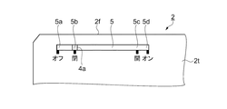
図2は、プロジェクター1の上面2tに位置するスリット5の周辺の拡大図であり、上面側から見た図である。また、図3(a)〜(d)は、プロジェクター1の開口部3周辺の拡大図であり、前面側から見た図である。ここで、図3(a)〜(d)は、シャッター4の開閉状態を示している。
図2に示すように、スリット5は、筐体2の前面2fと略平行に形成されており、シャッター4は、操作ツマミ4aがスリット5の左端部(前方に向かって左側の端部)5aに接する位置と、操作ツマミ4aがスリット5の右端部(前方に向かって右側の端部)5dに接する位置との間を移動可能になっている。
FIG. 2 is an enlarged view of the periphery of the
As shown in FIG. 2, the
操作ツマミ4aをスライド操作して、スリット5の左端部5aに移動させると、シャッター4は、図3(a)に示すように開口部3を閉塞し、投写レンズ13を覆ってその射出面を保護するとともに遮光状態にする。
次に操作ツマミ4aをスライド操作して、スリット5の右端部5dに移動させると、シャッター4は、図3(d)に示すように、投写レンズ13の前方(射出方向)から移動し、開口部3を開放させる。この結果、開口部3から投写レンズ13が露出し、画像光の投写が可能な状態となる。
When the
Next, when the
また、スリット5には左端部5aと右端部5dの間に位置5b、5cがある。
位置5bは左端部5a寄りにあり、操作ツマミ4aをスライド操作して、シャッター4をスリット5の位置5bに移動させることにより、左端部5aまで移動させなくても、図3(b)に示すように、シャッター4が開口部3を閉塞し、投写レンズ13を覆って画像光を遮光状態にすることができる。
また、位置5cは右端部5d寄りにあり、操作ツマミ4aをスライド操作して、シャッター4をスリット5の位置5cに移動させることにより、右端部5dまで移動させなくても、図3(c)に示すように、開口部3を開放させることができる。
なお、これ以降、操作ツマミ4aをスリット5の左端部5aに移動させたときのシャッター4の位置を「オフ位置」と呼び、操作ツマミ4aをスリット5の右端部5dに移動させたときのシャッター4の位置を「オン位置」と呼び、操作ツマミ4aをスリット5の位置5cに移動させたときのシャッター4の位置を「開位置」と呼び、操作ツマミ4aをスリット5の位置5bに移動させたときのシャッター4の位置を「閉位置」と呼ぶ。
The
The
Further, the position 5c is close to the right end portion 5d, and the
Hereinafter, the position of the
図4は、本実施形態のプロジェクターの概略構成を示すブロック図である。
図4に示すように、プロジェクター1は、画像投写手段10、OSD処理手段16、画像信号処理手段17、画像信号入力手段18、制御手段20、記憶手段21、光源制御手段22、入力操作手段23、シャッター位置検出手段25、報知手段26、電源端子30、電源部31等で構成されており、これらは筐体2(図1)の内部、または外面に収容されている。
FIG. 4 is a block diagram illustrating a schematic configuration of the projector according to the present embodiment.
As shown in FIG. 4, the
画像投写手段10は、光源11、光変調装置としての3つの液晶ライトバルブ12(12R,12G,12B)、投写光学系としての投写レンズ13、液晶駆動手段14等を含んでいる。画像投写手段10は、光源11から射出された光を、液晶ライトバルブ12R,12G,12Bで変調し、投写レンズ13から投写することによってスクリーンSC等の投写面に画像を表示する。
The image projection means 10 includes a
光源11は、超高圧水銀ランプやメタルハライドランプ等からなる放電型の光源ランプ11aと、光源ランプ11aが放射した光を液晶ライトバルブ12R,12G,12B側に反射するリフレクター11bとを含んで構成されている。光源11から射出された光は、図示しないインテグレーター光学系によって輝度分布が略均一な光に変換され、図示しない色分離光学系によって光の3原色である赤色(R),緑色(G),青色(B)の各色光成分に分離された後、それぞれ液晶ライトバルブ12R,12G,12Bに入射する。
The
液晶ライトバルブ12R,12G,12Bは、一対の透明基板間に液晶が封入された液晶パネル等によって構成される。液晶ライトバルブ12R,12G,12Bには、マトリックス状に配列された複数の画素(図示せず)が形成されており、液晶に対して画素毎に駆動電圧を印加可能となっている。
液晶駆動手段14が、入力される画像情報に応じた駆動電圧を各画素に印加すると、各画素は、画像情報に応じた光透過率に設定される。このため、光源11から射出された光は、この液晶ライトバルブ12R,12G,12Bを透過することによって変調され、画像情報に応じた画像光が色光毎に形成される。
形成された各色の画像光は、図示しない色合成光学系によって画素毎に合成されてカラーの画像光となった後、投写レンズ13によってスクリーンSC等に拡大投写される。
The liquid
When the liquid
The formed image light of each color is synthesized for each pixel by a color synthesis optical system (not shown) to become color image light, and then enlarged and projected onto the screen SC or the like by the
本実施形態では、光源として光源ランプ11aを用いて投写するプロジェクター1を例示したが、本発明は光源としてLED(Light Emitting Diode)光源やレーザー光源などを用いて投写するプロジェクターにも適用することができる。
In the present embodiment, the
なお、本実施形態では、画像投写手段10は、光変調装置としての3つの液晶ライトバルブ12R,12G,12Bを用いた透過型液晶方式の投写光学系を例示したが、反射型液晶表示方式やマイクロミラーデバイス方式(ライトスイッチ表示方式)など、他の表示方式の光変調装置を採用しても良い。
In the present embodiment, the
制御手段20は、図示しないCPU(Central Processing Unit)や、各種データ等の一時記憶に用いられるRAM(Random Access Memory)等を備え、記憶手段21に記憶されている制御プログラム(図示せず)に従って動作することによりプロジェクター1の動作を統括制御する。つまり、制御手段20は、記憶手段21とともにコンピューターとして機能する。制御手段20は、時間を計時するタイマー201を備える。
The control means 20 includes a CPU (Central Processing Unit) (not shown), a RAM (Random Access Memory) used for temporary storage of various data, and the like, according to a control program (not shown) stored in the storage means 21. By operating, the overall operation of the
記憶手段21は、図示しないフラッシュメモリーやFeRAM(Ferroelectric RAM:強誘電体メモリー)等の書き換え可能な不揮発性のメモリーにより構成されている。記憶手段21には、プロジェクター1の動作を制御するための制御プログラムや、プロジェクター1の動作条件等を規定する各種設定データ等が記憶されている。
The storage means 21 is composed of a rewritable nonvolatile memory such as a flash memory (not shown) or FeRAM (Ferroelectric RAM). The
入力操作手段23は、ユーザーがプロジェクター1に対して各種指示を行うための複数の操作キーを備えている。
入力操作手段23が備える操作キーとしては、電源のオン・オフを交互に切り替えるための電源キーや、画像信号入力手段18に入力される複数の画像入力端子を切り替えるための入力切替キー、各種設定を行うための設定メニューを重畳表示させるメニューキー、メニューからユーザーが設定項目を選択するカーソルキー、決定キー、エスケープキー、ヘルプキー等がある。
The input operation means 23 includes a plurality of operation keys for the user to give various instructions to the
The operation keys provided in the input operation means 23 include a power key for alternately switching on / off the power, an input switching key for switching a plurality of image input terminals input to the image signal input means 18, and various settings. There are a menu key for superimposing a setting menu for performing, a cursor key for selecting a setting item from the menu, a determination key, an escape key, a help key, and the like.
ユーザーが入力操作手段23の各種操作キーを操作すると、入力操作手段23は、ユーザーの操作内容に応じた操作信号を制御手段20に出力する。なお、入力操作手段23は、リモートコントローラー(リモコン)信号受信手段(図示せず)と遠隔操作が可能なリモートコントローラー(図示せず)を有した構成としてもよい。この場合、リモートコントローラーは、ユーザーの操作内容に応じた赤外線等の操作信号を発し、リモコン信号受信手段がこれを受信して制御情報として制御手段20に伝達する。
When the user operates various operation keys of the
画像信号入力手段18は、上述したように複数の画像入力端子を備えており、各画像入力端子より、ビデオ再生装置やパーソナルコンピューター等、外部の画像出力装置から、図示しないケーブル、又は通信機器などを介して画像情報が入力される。入力された画像情報は、制御手段20の指示に基づき、画像信号処理手段17に出力される。
The image signal input means 18 includes a plurality of image input terminals as described above, and from each image input terminal, an external image output device such as a video playback device or a personal computer, a cable or a communication device (not shown). The image information is input via. The input image information is output to the image
画像信号処理手段17は、画像信号入力手段18から入力される画像情報を、液晶ライトバルブ12R,12G,12Bの各画素の階調を表す画像情報に変換する。ここで、変換された画像情報は、赤(R),緑(G),青(B)の色光別になっており、各液晶ライトバルブ12R,12G,12Bのすべての画素に対応する複数の画素値によって構成されている。画素値とは、対応する画素の光透過率を定めるものであり、この画素値によって、各画素を透過し射出する光の強弱(階調)が規定される。
The image signal processing means 17 converts the image information input from the image signal input means 18 into image information representing the gradation of each pixel of the liquid
OSD処理手段16は、制御手段20の指示に基づいて、投写画像上に、メニュー画像やメッセージ画像等のOSD(オンスクリーンディスプレイ)画像を重畳して表示するための処理を行う。OSD処理手段16は、図示しないOSDメモリーを備えており、OSD画像を形成するための図形やフォント等を表すOSD画像情報を記憶している。
The
制御手段20が、OSD画像の重畳表示を指示すると、OSD処理手段16は、必要なOSD画像情報をOSDメモリーから読み出し、投写画像上の所定の位置にOSD画像が重畳されるように、画像信号処理手段17から入力される画像情報にこのOSD画像情報を合成する。OSD画像情報が合成された画像情報は、液晶駆動手段14に出力される。なお、制御手段20からOSD画像を重畳する旨の指示がない場合には、OSD処理手段16は、画像信号処理手段17から入力される画像情報を、そのまま液晶駆動手段14に出力する。制御手段20は、この他に、後述する電源オン・オフなどの制御を行う。
When the
液晶駆動手段14は、OSD処理手段16から入力される画像情報に従って液晶ライトバルブ12R,12G,12Bを駆動すると、液晶ライトバルブ12R,12G,12Bは、画像情報に応じた画像を形成し、この画像が投写レンズ13から投写される。
When the liquid
光源制御手段22は、制御手段20の指示に基づいて、光源11に対する電力の供給と停止とを制御し、光源11の点灯、及び消灯を切り替える。また、光源制御手段22は光源11の輝度を多段階で調整する機能を持つ。
The light
シャッター位置検出手段25は、図示しない複数のフォトセンサーやメカスイッチなどで構成され、シャッター4を操作ツマミ4aでスライド移動したときの位置がオン位置、開位置、閉位置、オフ位置のいずれの位置にあるかを検出し、その検出結果を制御手段20に通知する。
The shutter position detection means 25 is composed of a plurality of photo sensors and mechanical switches (not shown), and the position when the
報知手段26は、LEDやブザーなどで構成され、制御手段20の指示に基づき、プロジェクター1の動作状態を報知するものである。報知手段26が報知するプロジェクター1の動作状態としては、電源のオン・オフや異常発生、画像ミュート状態、シャッター4をオン位置またはオフ位置に保持している状態などがある。
The
電源部31には、AC100V等の電力が電源端子30を介して外部から供給される。電源部31は、例えば、商用電源(交流電源)を所定の電圧の直流電源に変換して、プロジェクター1の各部に電力を供給する。また、電源部31は、制御手段20の指示に基づいて、画像の投写に必要な電力(動作電力)を各部に供給する状態(電源オン状態)と、動作電力の供給を停止して、電源をオンにするための操作を待機する状態(スタンバイ状態)とを切り替えることができる。
Power such as AC 100 V is supplied to the
本実施形態のプロジェクター1は、上記のように構成されているため、電源端子30に電源ケーブル(図示せず)が接続され、電源部31に電力が供給されると、電源部31は、少なくとも制御手段20、記憶手段21、入力操作手段23に電力(スタンバイ電力)の供給を行い、制御手段20は、この電力供給を受けて、制御プログラムに従った動作を開始する。
電力が供給された直後には、プロジェクター1は、スタンバイ状態(「電源オフ状態」ともいう。)であり、光源11を消灯させた状態を維持している。そして、入力操作手段23に備わる電源キーがユーザーにより操作されると、制御手段20は、電源部31に指示をして、各部への動作電力の供給を開始させ、プロジェクター1を電源オン状態に移行させる。
Since the
Immediately after the power is supplied, the
次に、本実施形態のプロジェクター1のシャッター4の位置と動作状態の遷移を、図5を用いて説明する。
Next, the transition of the position and operation state of the
状態(a)はプロジェクター1が動作中でシャッター4が開位置にあり画像を投写している状態を示す。
状態(b)は状態(a)の状態からシャッター4を閉位置に移動させた状態を示す。この状態ではシャッター4が開口部3を閉鎖するため、投写光が遮断され、画像ミュート状態になる。状態(b)からシャッター4を開位置に移動させた場合は状態(a)に遷移し、画像の投写を再開する。
状態(c)は状態(b)の状態からシャッター4をオフ位置に移動させた状態を示す。この状態では、シャッター4が開口部3を閉鎖した画像ミュート状態が保持され、電源をオフするための時間待ち状態になる。
状態(d)は状態(c)のようにシャッター4がオフ位置で保持されたまま所定時間T1(例えば1秒)を経過した状態を示す。このとき、プロジェクター1は電源がオフされスタンバイ状態になる。状態(c)から所定時間T1を経過する前にシャッター4を閉位置に移動させた場合は状態(b)に遷移する。
状態(e)は状態(d)のようにプロジェクター1がスタンバイ状態でシャッター4がオン位置に移動した状態を示す。このとき、プロジェクター1はまだ電源オンせず、画像を投写しておらず、電源オン待ち状態になる。
状態(f)は状態(e)のようにシャッター4がオン位置で保持されたまま所定時間T3(例えば1秒)を経過した状態を示す。このとき、プロジェクター1は電源がオンされ画像の投写が開始される。
状態(f)から所定時間T2(例えば0.5秒)を経過する前にシャッター4を開位置に移動させた場合は状態(a)に遷移する。また、状態(f)は画像投写手段10の輝度を変更するための時間待ち状態にもなる。
状態(g)はプロジェクター1が電源オンした後、状態(f)のようにシャッター4がオン位置で保持されたまま所定時間T2(例えば0.5秒)を経過した状態を示す。このとき、プロジェクター1は画像投写手段10の輝度が所定のステップでアップまたはダウンし、再度状態(f)に遷移する。
State (a) shows a state in which the
The state (b) shows a state where the
State (c) shows a state in which the
The state (d) indicates a state in which a predetermined time T1 (for example, 1 second) has elapsed while the
The state (e) indicates a state in which the
The state (f) indicates a state in which a predetermined time T3 (for example, 1 second) has passed while the
When the
The state (g) indicates a state in which a predetermined time T2 (for example, 0.5 seconds) has passed after the
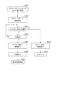
次に、本実施形態のプロジェクター1の動作を図6、及び図7のフローチャートを用いて説明する。図6はプロジェクター1が動作中にシャッター4が移動したことを検出したときの動作、図7はプロジェクター1がスタンバイ中にシャッター4がオン位置に移動したことを検出した時の動作を示すフローチャートである。本実施形態において、シャッター4はオン位置、開位置、閉位置、オフ位置のいずれかに設定されているものとする。
Next, the operation of the
(動作中にシャッター4が移動したことを検出したとき)
図6に示すように、プロジェクター1が動作中にシャッター4が他の位置に移動したことを検出すると(ステップS101)、ステップS102に遷移する。
(When it is detected that the
As shown in FIG. 6, when it is detected that the
ステップS102において制御手段20は、シャッター4が開位置にあるか否かを調べる。シャッター4が開位置にある場合(ステップS102:Y)、ステップS105に遷移する。シャッター4が開位置にない場合(ステップS102:N)、ステップS103に遷移する。
In step S102, the control means 20 checks whether or not the
ステップS103において制御手段20は、シャッター4が閉位置にあるか否かを調べる。シャッター4が閉位置にある場合(ステップS103:Y)、ステップS106に遷移する。シャッター4が閉位置にない場合(ステップS103:N)、ステップS104に遷移する。
In step S103, the control means 20 checks whether or not the
ステップS104において制御手段20は、シャッター4がオン位置にあるか否かを調べる。シャッター4がオン位置にある場合(ステップS104:Y)、ステップS112に遷移する。シャッター4がオン位置にない(つまりシャッター4がオフ位置にある)場合(ステップS104:N)、ステップS108に遷移する。なお、ステップS101からステップS104がシャッター位置検出ステップに相当する。
In step S104, the control means 20 checks whether the
ステップS105において制御手段20は、プロジェクター1の画像ミュート状態(画面ミュート)を解除して画像の投写を再開させ、ステップS107に遷移する。
In step S105, the
ステップS106において制御手段20は、プロジェクター1を画像ミュート状態にして画像の投写を中断させ、ステップS107に遷移する。
In step S106, the
ステップS107において本動作フローを終了する。 In step S107, the operation flow ends.
ステップS108において制御手段20は、プロジェクター1を画像ミュート状態にして画像の投写を中断させ、ステップS109に遷移する。
In step S108, the
ステップS109において制御手段20は、タイマー201による計時をスタートし、報知手段26によりシャッター4がオフ位置で保持されていることを報知し、ステップS110に遷移する。
In step S109, the
ステップS110において制御手段20は、シャッター4がオフ位置にあるか否かを調べる。シャッター4がオフ位置にある場合(ステップS110:Y)、ステップS111に遷移する。シャッター4がオフ位置にない(つまりシャッター4が他の位置に移動した)場合(ステップS110:N)、ステップS117に遷移する。
In step S110, the control means 20 checks whether or not the
ステップS111において制御手段20は、タイマー201による計時時間が所定時間T1(例えば1秒)を経過したか否かを調べる。タイマー201による計時時間が所定時間T1を経過した場合(ステップS111:Y)、ステップS118に遷移する。タイマー201による計時時間が所定時間T1を経過していない場合(ステップS111:N)、ステップS110に遷移する。
In step S111, the control means 20 checks whether or not the time measured by the
ステップS112において制御手段20は、プロジェクター1の画像ミュート状態を解除して画像の投写を再開させ、ステップS113に遷移する。
In step S112, the
ステップS113において制御手段20は、タイマー201による計時をスタートし、報知手段26によりシャッター4がオン位置で保持されていることを報知し、ステップS114に遷移する。
In step S113, the control means 20 starts the time measurement by the
ステップS114において制御手段20は、シャッター4がオン位置にあるか否かを調べる。シャッター4がオン位置にある場合(ステップS114:Y)、ステップS115に遷移する。シャッター4がオン位置にない(つまりシャッター4が他の位置に移動した)場合(ステップS114:N)、ステップS117に遷移する。
In step S114, the control means 20 checks whether or not the
ステップS115において制御手段20は、タイマー201による計時時間が所定時間T2(例えば0.5秒)を経過したか否かを調べる。タイマー201による計時時間が所定時間T2を経過した場合(ステップS115:Y)、ステップS116に遷移する。タイマー201による計時時間が所定時間T2を経過していない場合(ステップS115:N)、ステップS114に遷移する。
In step S115, the control means 20 checks whether or not the time measured by the
ステップS116において制御手段20は、光源制御手段22により光源11の輝度をあらかじめ定められたステップでアップまたはダウンし、ステップS113に遷移する。例えば光源11の輝度が最も明るくなっている場合は暗くなる方向に輝度をダウンさせる。
In step S116, the control means 20 increases or decreases the brightness of the
ステップS117において、制御手段20は、タイマー201の計時を停止し、次に報知手段26による報知を終了してステップS102に遷移する。
In step S117, the control means 20 stops the time measurement of the
ステップS118において、制御手段20は、タイマー201の計時を停止し、次に報知手段26による報知を終了してステップS119に遷移する。
In step S118, the control means 20 stops the timing of the
ステップS119において、制御手段20は、光源制御手段22により光源11を消灯し、ステップS120に遷移する。
In step S119, the
ステップS120において、制御手段20は、プロジェクター1の電源をオフしてスタンバイ状態に移行させ、本動作フローを終了する。なお、ステップS110からステップS111,ステップS118,ステップS119を経てステップS120に至る遷移が制御ステップに相当する。
In step S120, the
(スタンバイ中にシャッター4がオン位置に移動したことを検出したとき)
図7に示すように、プロジェクター1がスタンバイ中に、シャッター位置検出手段25によりシャッター4がオン位置に移動したことを検出すると(ステップS201)、ステップS202に遷移する。
(When it is detected that the
As shown in FIG. 7, when the
ステップS202において制御手段20は、タイマー201による計時をスタートし、報知手段26によりシャッター4がオン位置で保持されていることを報知し、ステップS203に遷移する。
In step S202, the
ステップS203において制御手段20は、シャッター4がオン位置にあるか(保持されているか)否かを調べる。シャッター4がオン位置にある場合(ステップS203:Y)、ステップS204に遷移する。シャッター4がオン位置にない、即ちシャッター4が他の位置に移動した場合(ステップS203:N)、ステップS209に遷移する。
In step S203, the control means 20 checks whether or not the
ステップS204において制御手段20は、タイマー201による計時時間が所定時間T3(例えば1秒)を経過したか否かを調べる。タイマー201による計時時間が所定時間T3を経過した場合(ステップS204:Y)、ステップS205に遷移する。タイマー201による計時時間が所定時間T3を経過していない場合(ステップS204:N)、ステップS203に遷移する。
In step S204, the control means 20 checks whether or not the time measured by the
ステップS205において、制御手段20は、タイマー201の計時を停止し、次に報知手段26による報知を終了してステップS206に遷移する。
In step S205, the control means 20 stops the time count of the
ステップS206において、制御手段20は、光源制御手段22により、光源11を点灯させ、ステップS207に遷移する。
In step S206, the
ステップS207において、制御手段20は、画像信号入力手段18より入力される画像信号に基づく画像を画像投写手段10に投写させ、本動作フローを終了する。
In step S207, the
ステップS209において、制御手段20は、タイマー201の計時を停止し、次に報知手段26による報知を終了してステップS210に遷移する。
In step S209, the control means 20 stops the time count of the
ステップS210において、制御手段20は、プロジェクター1をスタンバイ状態に移行させ、本動作フローを終了する。
In step S210, the
以上説明したように、本実施形態のプロジェクター1によれば、投写光を遮断するシャッター4をオフ位置で所定時間T1の間保持することによりプロジェクター1の電源をオフするので、誤ってシャッター4をオフ位置に移動させた場合でも、シャッター4を所定時間T1が経過する前に他の位置に移動させれば電源オフ操作を取り消すことが可能となる。
As described above, according to the
また、シャッター4をオン位置で所定時間T3の間保持することでプロジェクター1の電源をオンするので、誤ってシャッター4をオン位置に移動させた場合でも、シャッター4を所定時間T3が経過する前に他の位置に移動させれば電源オン操作を取り消すことが可能となる。
Further, since the
また、シャッター4がオフ位置またはオン位置に保持されている場合には、報知手段26により報知するので、ユーザーが誤ってシャッター4をオフ位置、またはオン位置に移動させた場合にシャッター4を他の位置に移動させるよう促すことが可能となる。
また、シャッター4を閉位置に移動させて投写光を遮断した後、シャッター4をオフ位置に移動させることで投写光の遮断状態を保持しながら電源をオフすることが可能となる。
In addition, when the
In addition, after the
また、シャッター4を開位置に移動させて開放した後、シャッター4をオン位置に移動させることで開放状態を保持しながら電源をオンすることが可能となる。
また、シャッター4を閉位置に移動させて投写を中断する画像ミュート状態にした後、シャッター4をオフ位置に移動させることで、画像ミュート状態を保持したまま電源をオフすることが可能となる。
また、プロジェクター1の電源オン後、シャッター4をオン位置で所定時間T2の間保持することで画像投写手段10の投写輝度を変更するので、面倒なメニュー操作を行うことなく、シャッター4の操作のみで電源オン後の輝度変更が可能となる。
Further, after the
In addition, after moving the
Further, since the projection brightness of the image projection means 10 is changed by holding the
また、上記実施形態は、以下のように変更してもよい。
(変形例1)
上記実施形態において、スリット5のオフ位置(5a)、オン位置(5d)にそれぞれスプリング機構を備え、操作ツマミ4aオフ位置、オン位置で保持した後、操作ツマミ4aを離すことにより、スプリング機構によって、シャッター4がそれぞれ閉位置(5b)、開位置(5c)に移動するようにしてもよい。これにより、ユーザーがシャッター4をオフ位置、オン位置で保持してプロジェクター1の電源がオフ、オンしたのを確認した後、操作ツマミ4aを離すだけで、シャッター4を閉位置、開位置に移動させるための操作が不要になる。また、シャッター4を開位置、閉位置へ移動させるつもりがオン位置、オフ位置まで移動させてしまった場合、操作ツマミ4aを離せば、シャッター4を所望の開位置、閉位置に移動させることができる。
Moreover, you may change the said embodiment as follows.
(Modification 1)
In the above embodiment, the spring mechanism is provided at each of the off position (5a) and the on position (5d) of the
(変形例2)
シャッター4がオフ位置で保持されたまま所定時間T1を経過した場合に、上記実施形態においては電源がオフされスタンバイ状態になっていたが、完全な電源オフ状態(その状態からシャッター4をオン位置に移動させても電源がオンしない状態)に移行させてもよい。この場合は、電源プラグを一度抜き差しするなどによって、プロジェクターをスタンバイ状態に移行させる。このような構成でも、上記実施形態と同様に、誤ってシャッター4をオフ位置に移動させた場合でも、シャッター4を所定時間T1内に他の位置に移動させれば電源オフ操作を取り消すことができる。
(Modification 2)
When the predetermined time T1 elapses while the
1…プロジェクター、4…シャッター、4a…操作ツマミ、5…スリット、10…画像投写手段、11…光源、12R,12G,12B…液晶ライトバルブ、13…投写レンズ、14…液晶駆動手段、16…OSD処理手段、17…画像信号処理手段、18…画像信号入力手段、20…制御手段、201…タイマー、21…記憶手段、22…光源制御手段、23…入力操作手段、25…シャッター位置検出手段、26…報知手段、30…電源端子、31…電源部。
DESCRIPTION OF
Claims (6)
前記画像投写手段を収容する筐体と、を備えたプロジェクターであって、
前記筐体に設けられ、前記画像投写手段からの投写光が通過する開口部と、
前記開口部を開閉可能なシャッターと、
前記シャッターの位置を検出するシャッター位置検出手段と、
前記シャッター位置検出手段の検出結果に基づき、前記シャッターが所定のオフ位置で所定時間保持された場合に、前記プロジェクターの電源をオフする制御手段と、を備え、
前記制御手段は、前記シャッター位置検出手段の検出結果に基づき、前記シャッターが所定のオン位置で所定時間保持された場合に、前記電源をオンし、
前記制御手段は、前記電源をオンした後、前記シャッターを前記オン位置に所定の時間保持された場合に、前記画像投写手段の輝度を変更することを特徴とする、プロジェクター。 Image projection means for modulating the light emitted from the light source according to the image information and projecting it on the projection surface;
A projector housing the image projecting means,
An opening provided in the housing and through which projection light from the image projection means passes;
A shutter capable of opening and closing the opening;
Shutter position detecting means for detecting the position of the shutter;
Control means for turning off the power of the projector when the shutter is held at a predetermined off position for a predetermined time based on the detection result of the shutter position detection means ,
The control means turns on the power when the shutter is held at a predetermined on position for a predetermined time based on a detection result of the shutter position detection means,
The projector, wherein after the power is turned on, the brightness of the image projection unit is changed when the shutter is held at the on position for a predetermined time .
前記シャッターが前記オフ位置、または前記オン位置で保持されているときに報知する報知手段、をさらに備えたことを特徴とする、プロジェクター。 The projector according to claim 1 ,
A projector further comprising an informing means for informing when the shutter is held at the off position or the on position.
前記シャッターは所定の閉位置にあるときに前記開口部を閉塞し、前記オフ位置は前記閉塞状態を保ちながら前記シャッターを移動させた位置、であることを特徴とする、プロジェクター。 The projector according to claim 1 or 2 ,
The projector, wherein the shutter closes the opening when the shutter is in a predetermined closed position, and the off position is a position where the shutter is moved while maintaining the closed state.
前記シャッターは所定の開位置にあるときに前記開口部を開放し、前記オン位置は、前記開放状態を保ちながら前記シャッターを移動させた位置、であることを特徴とする、プロジェクター。 The projector according to any one of claims 1 to 3 ,
The projector opens the opening when the shutter is in a predetermined open position, and the ON position is a position where the shutter is moved while maintaining the open state.
前記制御手段は、前記シャッターが前記オフ位置、および前記閉位置にあるときに前記画像投写手段による投写を中断する画像ミュート状態にすることを特徴とする、プロジェクター。 The projector according to claim 3 ,
The projector according to claim 1, wherein the control unit sets an image mute state in which projection by the image projection unit is interrupted when the shutter is in the off position and the closed position.
前記画像投写手段を収容する筐体に設けられ前記画像投写手段からの投写光が通過する開口部と、前記開口部を開閉可能なシャッターと、を備えたプロジェクターの制御方法であって、
前記シャッターの位置を検出するシャッター位置検出ステップと、
前記シャッター位置検出ステップにより、前記シャッターが所定のオフ位置で所定時間保持されたことが検出された場合に、前記プロジェクターの電源をオフする制御ステップと、
前記シャッター位置検出ステップでの検出結果に基づき、前記シャッターが所定のオン位置で所定時間保持された場合に、前記電源をオンするステップと、
前記電源をオンした後、前記シャッターを前記オン位置に所定の時間保持された場合に、前記画像投写手段の輝度を変更するステップと、
を有することを特徴とする、プロジェクターの制御方法。 Image projection means for modulating the light emitted from the light source according to the image information and projecting it on the projection surface;
A method for controlling a projector, comprising: an opening provided in a housing that accommodates the image projection means, through which projection light from the image projection means passes; and a shutter that can open and close the opening,
A shutter position detecting step for detecting the position of the shutter;
A control step of turning off the power of the projector when the shutter position detecting step detects that the shutter is held at a predetermined off position for a predetermined time;
Based on the detection result in the shutter position detection step, when the shutter is held at a predetermined on position for a predetermined time, turning on the power supply;
Changing the brightness of the image projection means when the shutter is held in the on position for a predetermined time after turning on the power;
A projector control method comprising the steps of:
Priority Applications (2)
| Application Number | Priority Date | Filing Date | Title |
|---|---|---|---|
| JP2012176775A JP6069942B2 (en) | 2012-08-09 | 2012-08-09 | Projector and projector control method |
| US13/961,999 US9261757B2 (en) | 2012-08-09 | 2013-08-08 | Projector and method for controlling projector using a slidable lens shutter |
Applications Claiming Priority (1)
| Application Number | Priority Date | Filing Date | Title |
|---|---|---|---|
| JP2012176775A JP6069942B2 (en) | 2012-08-09 | 2012-08-09 | Projector and projector control method |
Publications (3)
| Publication Number | Publication Date |
|---|---|
| JP2014035461A JP2014035461A (en) | 2014-02-24 |
| JP2014035461A5 JP2014035461A5 (en) | 2015-09-03 |
| JP6069942B2 true JP6069942B2 (en) | 2017-02-01 |
Family
ID=50065961
Family Applications (1)
| Application Number | Title | Priority Date | Filing Date |
|---|---|---|---|
| JP2012176775A Expired - Fee Related JP6069942B2 (en) | 2012-08-09 | 2012-08-09 | Projector and projector control method |
Country Status (2)
| Country | Link |
|---|---|
| US (1) | US9261757B2 (en) |
| JP (1) | JP6069942B2 (en) |
Families Citing this family (3)
| Publication number | Priority date | Publication date | Assignee | Title |
|---|---|---|---|---|
| JP7067539B2 (en) * | 2019-09-26 | 2022-05-16 | セイコーエプソン株式会社 | Projector control method and projector |
| JP2022077600A (en) * | 2020-11-12 | 2022-05-24 | セイコーエプソン株式会社 | Color measuring device |
| JP2022077753A (en) | 2020-11-12 | 2022-05-24 | セイコーエプソン株式会社 | Color measuring device |
Family Cites Families (13)
| Publication number | Priority date | Publication date | Assignee | Title |
|---|---|---|---|---|
| US6570621B2 (en) * | 2001-05-21 | 2003-05-27 | Hewlett-Packard Development Company, L.P. | Lens cap detection |
| JP4734851B2 (en) * | 2004-05-14 | 2011-07-27 | カシオ計算機株式会社 | Projection apparatus, projection control method, and program |
| JP2007004031A (en) * | 2005-06-27 | 2007-01-11 | Olympus Imaging Corp | Projector apparatus |
| JP4710657B2 (en) | 2006-03-03 | 2011-06-29 | セイコーエプソン株式会社 | projector |
| JP2009042677A (en) * | 2007-08-10 | 2009-02-26 | Toshiba Corp | Projector device and method of controlling projector device |
| JP2009075305A (en) * | 2007-09-20 | 2009-04-09 | Seiko Epson Corp | Projector and control method |
| US8573781B2 (en) * | 2007-10-30 | 2013-11-05 | Seiko Epson Corporation | Projector and control method for the same |
| JP2009135877A (en) * | 2007-10-30 | 2009-06-18 | Seiko Epson Corp | Projector and method of controlling the same |
| JP2010113265A (en) * | 2008-11-10 | 2010-05-20 | Seiko Epson Corp | Projector, and image mute setting/canceling method in projector |
| JP2010281863A (en) * | 2009-06-02 | 2010-12-16 | Seiko Epson Corp | Projector |
| JP2011197385A (en) * | 2010-03-19 | 2011-10-06 | Seiko Epson Corp | Projector and image projection method with projector |
| JP2012027055A (en) * | 2010-07-20 | 2012-02-09 | Seiko Epson Corp | Projector and projector control method |
| JP2012093605A (en) | 2010-10-28 | 2012-05-17 | Seiko Epson Corp | Projection type display device and control method thereof |
-
2012
- 2012-08-09 JP JP2012176775A patent/JP6069942B2/en not_active Expired - Fee Related
-
2013
- 2013-08-08 US US13/961,999 patent/US9261757B2/en active Active
Also Published As
| Publication number | Publication date |
|---|---|
| JP2014035461A (en) | 2014-02-24 |
| US9261757B2 (en) | 2016-02-16 |
| US20140043590A1 (en) | 2014-02-13 |
Similar Documents
| Publication | Publication Date | Title |
|---|---|---|
| JP5573240B2 (en) | Projector and image projection method using projector | |
| JP2013105171A (en) | Projector and control method of the same | |
| JP6127757B2 (en) | Projector and projector control method | |
| JP2009075305A (en) | Projector and control method | |
| JP6069942B2 (en) | Projector and projector control method | |
| JP2012215756A (en) | Projector and control method for projector | |
| JP2009042677A (en) | Projector device and method of controlling projector device | |
| JP2009276649A (en) | Image display device, projector, and control method for image display device | |
| US20140085272A1 (en) | Projector system and control method for the projector system | |
| JP6056204B2 (en) | Projector and projector control method | |
| JP6171379B2 (en) | Projector and projector control method | |
| JP5834746B2 (en) | Projector and projector control method | |
| JP6070871B2 (en) | Projector and control method thereof | |
| JP2013029642A (en) | Image display device and control method of the same | |
| JP2011197385A (en) | Projector and image projection method with projector | |
| JP5625950B2 (en) | Projector system and method for controlling projector system | |
| JP2012141486A (en) | Projector and control method of the same | |
| JP2013190617A (en) | Projector and control method of projector | |
| JP2012220599A (en) | Projector and method of controlling the projector | |
| JP2014126760A (en) | Projector and control method of projector | |
| JP2012252133A (en) | Projector and control method of projector | |
| JP2009042507A (en) | Projector and its control method | |
| JP2009063959A (en) | Projector and its control method | |
| JP2015018151A (en) | Projector and projector control method | |
| JP2014048617A (en) | Projector, and control method of projector |
Legal Events
| Date | Code | Title | Description |
|---|---|---|---|
| RD04 | Notification of resignation of power of attorney |
Free format text: JAPANESE INTERMEDIATE CODE: A7424 Effective date: 20150108 |
|
| A521 | Request for written amendment filed |
Free format text: JAPANESE INTERMEDIATE CODE: A523 Effective date: 20150710 |
|
| A621 | Written request for application examination |
Free format text: JAPANESE INTERMEDIATE CODE: A621 Effective date: 20150710 |
|
| A977 | Report on retrieval |
Free format text: JAPANESE INTERMEDIATE CODE: A971007 Effective date: 20160526 |
|
| A131 | Notification of reasons for refusal |
Free format text: JAPANESE INTERMEDIATE CODE: A131 Effective date: 20160531 |
|
| RD04 | Notification of resignation of power of attorney |
Free format text: JAPANESE INTERMEDIATE CODE: A7424 Effective date: 20160610 |
|
| RD03 | Notification of appointment of power of attorney |
Free format text: JAPANESE INTERMEDIATE CODE: A7423 Effective date: 20160624 |
|
| A521 | Request for written amendment filed |
Free format text: JAPANESE INTERMEDIATE CODE: A523 Effective date: 20160727 |
|
| TRDD | Decision of grant or rejection written | ||
| A01 | Written decision to grant a patent or to grant a registration (utility model) |
Free format text: JAPANESE INTERMEDIATE CODE: A01 Effective date: 20161206 |
|
| A61 | First payment of annual fees (during grant procedure) |
Free format text: JAPANESE INTERMEDIATE CODE: A61 Effective date: 20161219 |
|
| R150 | Certificate of patent or registration of utility model |
Ref document number: 6069942 Country of ref document: JP Free format text: JAPANESE INTERMEDIATE CODE: R150 |
|
| LAPS | Cancellation because of no payment of annual fees |