JP2010054283A - Device and method for measuring shape change - Google Patents
Device and method for measuring shape change Download PDFInfo
- Publication number
- JP2010054283A JP2010054283A JP2008218317A JP2008218317A JP2010054283A JP 2010054283 A JP2010054283 A JP 2010054283A JP 2008218317 A JP2008218317 A JP 2008218317A JP 2008218317 A JP2008218317 A JP 2008218317A JP 2010054283 A JP2010054283 A JP 2010054283A
- Authority
- JP
- Japan
- Prior art keywords
- displacement
- observation
- axis
- image
- target mark
- Prior art date
- Legal status (The legal status is an assumption and is not a legal conclusion. Google has not performed a legal analysis and makes no representation as to the accuracy of the status listed.)
- Granted
Links
Images


Landscapes
- Image Analysis (AREA)
- Length Measuring Devices By Optical Means (AREA)
- Processing Or Creating Images (AREA)
- Image Processing (AREA)
Abstract
Description
本発明は、測定対象物に固定された複数の測定対象マークの変位を測定し、測定結果に基づいて測定対象物の形状の変化を画像として表示する形状変化測定装置及び方法に関する。 The present invention relates to a shape change measurement apparatus and method for measuring displacement of a plurality of measurement object marks fixed to a measurement object and displaying a change in shape of the measurement object as an image based on a measurement result.
2台のカメラを用いて同一のマークを撮像することにより、ステレオ計測を行うことができる(特許文献1)。一般的なステレオ計測を行う際には、2つのカメラのレンズの光軸を相互に平行に配置し、光軸方向に関して、2つのカメラのレンズの主点の位置を一致させる。1つの目標マークを2つのカメラで同時に撮像することにより、目標マークの位置を検出することができる。 Stereo measurement can be performed by imaging the same mark using two cameras (Patent Document 1). When performing general stereo measurement, the optical axes of the lenses of the two cameras are arranged in parallel to each other, and the positions of the principal points of the lenses of the two cameras are matched with respect to the optical axis direction. The position of the target mark can be detected by simultaneously imaging one target mark with two cameras.
従来のステレオ計測においては、2つのカメラの位置及び姿勢に高い精度が要求される。また、1つのマークを2つのカメラで同時に撮像する必要があるため、計測時のカメラの設置条件が制約を受ける。また、静止したマークの位置の測定には有用であるが、マークの位置の変位の時刻暦の測定には適さない。 In conventional stereo measurement, high accuracy is required for the position and orientation of the two cameras. In addition, since it is necessary to capture one mark with two cameras at the same time, the camera installation conditions during measurement are restricted. Although it is useful for measuring the position of a stationary mark, it is not suitable for measuring the time calendar of the displacement of the mark position.
本発明の一観点によると、
測定対象マークを観測し、該測定対象マークの位置情報を取得する第1の観測装置と、
画像を出力する画像出力装置と、
前記第1の観測装置及び前記画像出力装置を制御する制御装置と
を有し、
前記制御装置は、
測定対象物に対応する解析モデルを複数の有限要素に区分し、該有限要素の節点の位置を記憶し、
前記測定対象物上に定義された複数の測定対象マークの位置を記憶し、
前記測定対象物に力学的作用を与えたときの、前記測定対象マークの各々の位置情報の時刻暦を、前記第1の観測装置から取得し、
前記第1の観測装置から取得した前記位置情報の時刻暦に基づいて、前記節点の各々の変位を算出し、
前記節点の各々の変位に基づいて、前記測定対象物の形状または姿勢の変化を、前記画像出力装置表示させる形状変化測定装置が提供される。
According to one aspect of the invention,
A first observation device that observes the measurement target mark and obtains position information of the measurement target mark;
An image output device for outputting an image;
A control device for controlling the first observation device and the image output device;
The control device includes:
The analysis model corresponding to the measurement object is divided into a plurality of finite elements, and the positions of the nodes of the finite elements are stored.
Storing the positions of a plurality of measurement object marks defined on the measurement object;
Obtaining a time calendar of each position information of the measurement target mark when a mechanical action is given to the measurement target object from the first observation device;
Based on the time calendar of the position information acquired from the first observation device, to calculate the displacement of each of the nodes,
A shape change measuring device is provided that displays a change in the shape or posture of the measurement object on the image output device based on the displacement of each of the nodes.
本発明の他の観点によると、
測定対象物に対応する解析モデルを複数の有限要素に区分し、有限要素同士の節点の位置を確定する工程と、
前記測定対象物に固定された複数の測定対象マークの位置の時刻暦を測定する工程と、
前記測定対象マークの位置の時刻暦に基づいて、前記節点の各々の変位の時刻暦を算出する工程と、
前記節点の各々の変位の時刻暦に基づいて、前記測定対象物の形状の変化を画像として表示する工程と
を有する形状変化測定方法が提供される。
According to another aspect of the invention,
Dividing the analysis model corresponding to the measurement object into a plurality of finite elements, and determining the positions of the nodes between the finite elements;
Measuring a time calendar of the position of a plurality of measurement object marks fixed to the measurement object;
Calculating a time calendar of displacement of each of the nodes based on a time calendar of the position of the measurement target mark;
And a step of displaying a change in shape of the measurement object as an image based on a time calendar of the displacement of each of the nodes.
実際に観測した観測対象マークの変位量から、節点の変位量を算出することにより、観測対象物の形状の変化を画像表示することが可能になる。これにより、形状の変化を容易に視認することができる。 By calculating the displacement amount of the node from the actually observed displacement amount of the observation target mark, it is possible to display an image of the change in the shape of the observation target object. Thereby, the change of shape can be visually recognized easily.
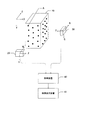
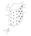
図1に、実施例による形状変化測定装置の概略図を示す。XYZ直交座標系(グローバル座標系)が定義された空間に、測定対象物10が配置される。測定対象物10の表面に、複数の測定対象マークAが固定されている。測定対象マークAは、測定対象物10の表面に直接描画することにより形成してもよいし、マークが形成された部材を測定対象物10の表面に貼り付けてもよい。
FIG. 1 shows a schematic diagram of a shape change measuring apparatus according to an embodiment. The
測定対象物10は、外力が加えられることにより変形する。測定対象物10が変形すると、測定対象マークAが変位する。
The
第1の観測装置20及び第2の観測装置30が、測定対象マークAを観測する。第1の観測装置20及び第2の観測装置30には、例えば、ディジタルカメラが用いられる。観測対象マークAに、1からnまで通番を付したとき、一部の観測対象マークA1〜Aiが第1の観測装置20で観測され、他の観測対象マークAi+1〜Anが第2の観測装置30で観測される。なお、すべての観測対象マークA1〜Anが、両方の観測装置20及び30で観測されるようにしてもよいし、一部の観測対象マークAj〜Aj+mが、両方の観測装置20及び30で観測されるようにしてもよい。
The
第1の観測装置20及び第2の観測装置30の各々は、レンズと受像面とを含む。第1の観測装置20に固定された第1のローカル座標系が定義され、第2の観測装置30に固定された第2のローカル座標系が定義される。第1のローカル座標系は、第1の観測装置20のレンズの光軸に一致するW軸、W軸に垂直で、かつ相互に直交するU軸及びV軸で定義され、その原点は、レンズの主点に一致する。受像面は、UV面に平行である。第2のローカル座標系は、第2の観測装置30のレンズの光軸に一致するT軸、T軸に垂直で、かつ相互に直交するR軸及びS軸で定義され、その原点は、レンズの主点に一致する。受像面は、RS面に平行である。
Each of the
第1の観測装置20及び第2の観測装置30で撮像された画像データが、処理装置40に入力される。処理装置40は、入力された画像データを処理し、観測対象物10の形状変化の時刻暦を求める。形状変化の時刻暦は、画像表示装置41に画像として表示される。
Image data captured by the
図2に、実施例による形状変化測定方法のフローチャートを示す。まず、ステップSA1において、CADを用いて測定対象物の形状を定義する。測定対象物の形状は、CAD座標系内に定義される。 FIG. 2 shows a flowchart of the shape change measuring method according to the embodiment. First, in step SA1, the shape of the measurement object is defined using CAD. The shape of the measurement object is defined in the CAD coordinate system.
ステップSA2において、CAD座標系と関連付けたグローバル座標系(XYZ座標系)を定義する。通常は、CAD座標系をグローバル座標系として採用すればよい。 In step SA2, a global coordinate system (XYZ coordinate system) associated with the CAD coordinate system is defined. Usually, the CAD coordinate system may be adopted as the global coordinate system.
ステップSA3において、CADで定義された測定対象物を、仮想的に複数の有限要素に分割する。 In step SA3, the measurement object defined by CAD is virtually divided into a plurality of finite elements.
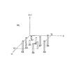
図3に、有限要素に分割された測定対象物10を示す。測定対象物10の表面に複数の測定対象マークAが固定されている。図3は、測定対象物10が立方体の多数の要素に分割された例を示している。各要素の頂点に節点Bが画定される。各要素を、多角形の表面を持つ任意の立体形状としてもよい。この場合、多角形の表面の頂点が節点Bとなる。制御装置40は、グローバル座標系における各節点Bの位置を記憶する。
FIG. 3 shows the
ステップSA4において、実際の測定対象物10に取り付けられている測定対象マークAのグローバル座標系における位置を、制御装置40に記憶させる。
In step SA4, the position of the measurement target mark A attached to the
ステップSA5において、グローバル座標系が定義された空間内に、第1の観測装置20及び第2の観測装置30を配置し、固定する。制御装置40に、第1の観測装置20及び第2の観測装置30の、グローバル座標系内における位置と姿勢を記憶させる。第1の観測装置20の位置は、そのレンズの主点のグローバル座標で特定される。第1の観測装置20の姿勢は、そのレンズの光軸、即ちW軸の方向と、U軸の方向とで特定される。同様に、第2の観測装置30の位置は、そのレンズの主点のグローバル座標で特定され、姿勢は、T軸及びR軸の方向で特定される。
In step SA5, the
実施例では、第1の観測装置20に固定された第1のローカル座標系のW軸が、グローバル座標系のZ軸に平行になり、第2の観測装置30に固定された第2のローカル座標系のT軸が、グローバル座標系のX軸に平行になるように、第1及び第2の観測装置20、30を配置した。この配置の場合、第1の観測装置20は、W軸に直交する方向、すなわちXY面内方向の変位を観測し、第2の観測装置30は、T軸に直交する方向、すなわちYZ面内方向の変位を観測することができる。
In the embodiment, the W axis of the first local coordinate system fixed to the
観測対象物10に予想される変形に応じて、第1及び第2の観測装置20、30を配置することが好ましい。例えば、外力の向きがXY面に平行であり、その大きさがZ方向に関してほぼ一定であれば、測定対象物10の変形は、ほぼXY面に平行な方向に生じると予測される。この変形は、主として第1の観測装置20によって観測することができる。
It is preferable to arrange the first and
以下の説明では、観測対象物10が、主としてXY面内に平行な方向に変形すると予測される場合について説明する。
In the following description, a case will be described in which the
ステップSA6において、測定対象物10に外力を加えながら、観測対象マークAを、第1の観測装置20及び第2の観測装置30で撮像する。撮像された画像データは、制御装置40に入力される。制御装置40は、画像解析を行うことにより、受像面内における観測対象マークAの像の位置を計測する。以下の工程では、第1の観測装置20で取得された画像データの処理について説明する。第2の観測装置30で取得された画像データの処理も、同様に行われる。
In step SA6, the observation object mark A is imaged by the
第1の観測装置20の受像面は、第1のローカル座標系のUV面に平行である。このため、受像面内の位置は、U座標及びV座標で特定される。観測時刻t0、t1、t2・・・における画像データを解析することにより、これらの観測時刻における観測対象マークAの受像面内の位置、すなわち(U,V)座標を検出する。以下、観測対象マークA1の位置の検出方法の一例について説明する。
The image receiving plane of the
まず、画像データから、観測対象マークA1を含む長方形の領域を切り取る。切り取られた領域の(U,V)座標、例えば長方形の1つの頂点の(U,V)座標を記憶する。切り取られた画像データに、ノイズ除去を目的として、低域通過フィルタ、または収縮膨張操作等の処理を行う。ノイズが除去された画像データを用い、切り取られた領域内における観測対象マークA1の位置を検出する。 First, from the image data, cut out a rectangular region including the observation target marks A 1. The (U, V) coordinates of the clipped area, for example, the (U, V) coordinates of one vertex of the rectangle are stored. The cut image data is subjected to processing such as a low-pass filter or contraction / expansion operation for the purpose of noise removal. Using the image data from which noise is removed, detecting a position of the observation target marks A 1 in cropped area.
マーク位置の検出には、重心演算かピーク値検出法を用いることが好ましい。マークの像がぼやけている場合があるため、エッジ検出法やパターンマッチング法による位置検出は適さない。光強度にしきい値を設定し、しきい値以上の画素についてのみ重心演算を行うことにより、背景の光強度の強弱の影響を受けにくくすることができる。 For the detection of the mark position, it is preferable to use the center of gravity calculation or the peak value detection method. Since the mark image may be blurred, position detection by the edge detection method or pattern matching method is not suitable. By setting a threshold value for the light intensity and performing the centroid calculation only for pixels that are equal to or greater than the threshold value, it is possible to make it less susceptible to the influence of the background light intensity.
切り取られた領域の位置、及び切り取られた領域内における観測対象マークA1の位置により、受像面内における観測対象マークA1の(U,V)座標を算出することができる。同様の方法で、他の観測対象マークA2〜Anの(U,V)座標を求める。 Position of the cropped area, and the cut position of the observation target marks A 1 in the region, it is possible to calculate the observation target marks A 1 of (U, V) coordinates in the image receiving plane. In a similar way, determine the (U, V) coordinates of another observation target mark A 2 to A n.
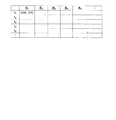
図4に示すように、観測対象マークA1、A2・・・ごとに、座標及び変位量の時刻暦テーブルが準備されている。この時刻暦テーブルには、時刻ごとに、(U,V)座標及び変位量(ΔU,ΔV)を記憶する領域が確保されている。求められた(U,V)座標の値を、図4に示した時刻暦テーブルの(U,V)座標記憶領域に記憶する。 As shown in FIG. 4, a time calendar table of coordinates and displacement amounts is prepared for each of the observation target marks A 1 , A 2 . In this time calendar table, an area for storing (U, V) coordinates and displacement amounts (ΔU, ΔV) is secured for each time. The obtained (U, V) coordinate values are stored in the (U, V) coordinate storage area of the time calendar table shown in FIG.
ステップSA7において、観測対象マークAの各々の受像面内における時刻暦から、観測対象マークAの各々について、観測時刻ごとの変位を計算する。例えば、観測対象マークA1の時刻t0及びt1における位置が(U10,V10)及び(U11,V11)である場合、観測時刻t1における観測対象マークA1の変位(ΔU11,ΔV11)は、(U11−U10、V11−V10)になる。図4に示した時刻暦テーブルの変位量記憶領域に、計算により求められた変位量(ΔU,ΔV)を記憶する。 In step SA7, the displacement at each observation time is calculated for each observation target mark A from the time calendar in the image receiving plane of each observation target mark A. For example, when the positions of the observation target mark A 1 at the times t 0 and t 1 are (U 10 , V 10 ) and (U 11 , V 11 ), the displacement (ΔU of the observation target mark A 1 at the observation time t 1 11 , ΔV 11 ) becomes (U 11 −U 10 , V 11 −V 10 ). The displacement amounts (ΔU, ΔV) obtained by calculation are stored in the displacement amount storage area of the time calendar table shown in FIG.
次に、観測対象マークごと、及び観測時刻ごとの変位量から、(U,V)座標上で抽出された複数の点(抽出点)における変位量を観測時刻ごとに算出し、算出結果を記憶する。以下、抽出点の変位量を算出する方法について説明する。 Next, the displacement amount at a plurality of points (extraction points) extracted on the (U, V) coordinates is calculated for each observation time from the displacement amount for each observation target mark and each observation time, and the calculation result is stored. To do. Hereinafter, a method for calculating the displacement amount of the extraction point will be described.
図5に、算出された変位量を記憶するテーブルの一例を示す。観測時刻ごとに、抽出点の変位量を記憶するテーブルが準備されている。抽出点は、例えば、U軸方向及びV軸方向に、ある格子間隔で設けた正方格子の格子点に一致するように抽出される。抽出点のU座標は、U1、U2、U3・・・となり、V座標は、V1、V2、V3・・・となる。抽出点ごとに、変位量(ΔU,ΔV)を記憶する領域が確保されている。 FIG. 5 shows an example of a table that stores the calculated displacement amount. A table for storing the displacement amount of the extraction point is prepared for each observation time. For example, the extraction points are extracted so as to coincide with the lattice points of a square lattice provided at a certain lattice interval in the U-axis direction and the V-axis direction. The U coordinates of the extraction points are U 1 , U 2 , U 3 ..., And the V coordinates are V 1 , V 2 , V 3 . An area for storing the displacement (ΔU, ΔV) is secured for each extraction point.
図6を参照して、抽出点(Ui,Vj)における変位量の算出方法について説明する。(U,V)平面上に、複数の観測対象マークA1〜Anが分布する。観測時刻t1における観測対象マークA1〜Anの各々のU軸方向の変位量ΔUは、図4に示したように既に求められている。抽出点(Ui,Vj)における変位量は、変位量が既知の複数の点の変位量から、例えば補間演算等により推測することができる。V軸方向の変位量ΔVも、同様に推測することができる。観測時刻t2以降の各観測時刻について同様の処理を行い、観測時刻ごとに、図5に示したテーブルの変位量記憶領域に、算出された変位量を格納する。 With reference to FIG. 6, a method of calculating the displacement amount at the extraction point (U i , V j ) will be described. A plurality of observation object marks A 1 to An are distributed on the (U, V) plane. Displacement ΔU of each U-axis direction of the observation target marks A 1 to A n at the observation time t 1 has already been determined as shown in FIG. The displacement amount at the extraction point (U i , V j ) can be estimated from the displacement amounts of a plurality of points whose displacement amounts are known, for example, by interpolation calculation. The displacement amount ΔV in the V-axis direction can be similarly estimated. Performs the same processing for each observation time of the observation time t 2 later, for each observation time, the displacement of storage area of the table shown in FIG. 5, it stores the calculated displacement.
なお、図5に示した変位量記憶用のテーブルを準備する代わりに、変位量の近似関数を決定してもよい。変位量の近似関数fu、fvは、受像面上の位置を(U,V)とし、経過時間をtとして、下記のように表記することができる。
ΔU=fu(U,V,t)
ΔV=fv(U,V,t)
ステップSA8において、レンズ特性を考慮して、受像面上の(U,V)座標を、第1のローカル座標系のW軸を基準とした極角θ、及びUW面を基準とした方位角φに変換する。さらに、変位量ΔU及びΔVも、極角の変化量Δθ及び方位角の変化量Δφに変換する。以下、変換方法について説明する。
Instead of preparing the displacement amount storage table shown in FIG. 5, an approximate function of the displacement amount may be determined. The approximate functions fu and fv of the displacement amount can be expressed as follows, where the position on the image receiving surface is (U, V) and the elapsed time is t.
ΔU = fu (U, V, t)
ΔV = fv (U, V, t)
In step SA8, in consideration of lens characteristics, the (U, V) coordinates on the image receiving surface are set to polar angle θ with reference to the W axis of the first local coordinate system, and azimuth angle φ with reference to the UW surface. Convert to Further, the displacement amounts ΔU and ΔV are also converted into a polar angle variation Δθ and an azimuth variation Δφ. Hereinafter, the conversion method will be described.
図7に示すように、レンズが薄い単レンズの場合、レンズの主点21から受像面22までの距離Lが既知であれば、観測対象マークAの像AIの(U,V)座標を、(θ、φ)に変換することができる。さらに、変位量(ΔU、ΔV)を、角度の変化量(Δθ,Δφ)に変換することができる。なお、複合レンズを用いる場合にも、レンズ特性に基づいて、変位量(ΔU、ΔV)を角度の変化量(Δθ,Δφ)に変換することができる。
As shown in FIG. 7, when the lens is a thin single lens, if the distance L from the
図8に示すように、観測時刻ごとに、抽出点に対応する(θ、φ)座標と、角度の変化量(Δθ、Δφ)との関係を示す角度変化量テーブルが準備されている。角度変化量テーブルには、抽出点ごとに、角度変化量を記憶する領域が確保されている。変換により算出された角度変化量(Δθ,Δφ)を、角度変化量の記憶領域に格納する。 As shown in FIG. 8, for each observation time, an angle change amount table showing the relationship between the (θ, φ) coordinates corresponding to the extraction point and the angle change amounts (Δθ, Δφ) is prepared. In the angle change amount table, an area for storing the angle change amount is secured for each extraction point. The angle change amounts (Δθ, Δφ) calculated by the conversion are stored in the storage area for the angle change amount.
なお、図8に示した角度変化量テーブルの代わりに、角度変化量の近似関数を決定してもよい。角度変化量の近似関数fθ、fφは、極角をθ、方位角をφ、経過時間をtとして、下記のように表記することができる。
Δθ=fθ(θ,φ,t)
Δφ=fφ(θ,φ,t)
ステップSA9において、図8に示した角度変化量テーブルに基づいて、第1の観測装置20で観測されている表面上の節点Bの各々の角度変化量(Δθ,Δφ)を、観測時刻ごとに算出する。
Instead of the angle change amount table shown in FIG. 8, an approximate function of the angle change amount may be determined. The approximate functions fθ and fφ of the angle change amount can be expressed as follows, where the polar angle is θ, the azimuth angle is φ, and the elapsed time is t.
Δθ = fθ (θ, φ, t)
Δφ = fφ (θ, φ, t)
In step SA9, based on the angle change amount table shown in FIG. 8, each angle change amount (Δθ, Δφ) of the node B on the surface observed by the
節点Bのグローバル座標は、ステップSA3で既に記憶されている。グローバル座標系と第1のローカル座標系との関係は、ステップSA5で既に記憶されているため、節点Bのグローバル座標から、当該節点Bのローカル座標(θ、φ)を求めることができる。図8に示した角度変化量テーブルを参照して、節点Bのローカル座標(θ,φ)から、その角度変化量(Δθ,Δφ)を、補間演算等により算出することができる。 The global coordinates of node B are already stored in step SA3. Since the relationship between the global coordinate system and the first local coordinate system is already stored in step SA5, the local coordinates (θ, φ) of the node B can be obtained from the global coordinates of the node B. With reference to the angle change amount table shown in FIG. 8, the angle change amounts (Δθ, Δφ) can be calculated from the local coordinates (θ, φ) of the node B by interpolation or the like.
図9に示すように、節点B1、B2・・・の角度変化量(Δθ,Δφ)の時刻暦を記憶するためのテーブルが準備されている。このテーブルには、節点ごと、及び観測時刻ごとに、角度変化量(Δθ,Δφ)を記憶する領域が確保されている。算出された角度変化量(Δθ,Δφ)を、図9に示したテーブルの角度変化量記憶領域に格納する。 As shown in FIG. 9, a table for storing the time calendar of the angle change amounts (Δθ, Δφ) of the nodes B 1 , B 2 ... Is prepared. In this table, an area for storing the amount of change in angle (Δθ, Δφ) is secured for each node and each observation time. The calculated angle change amounts (Δθ, Δφ) are stored in the angle change amount storage area of the table shown in FIG.
ステップSA10において、第1の観測装置20で観測されている表面上の節点Bの各々の角度変化量(Δθ,Δφ)を、グローバル座標系における変位量(ΔX,ΔY)に変換する。
In step SA10, each angle change amount (Δθ, Δφ) of the node B on the surface observed by the
図10を参照して、節点B1の角度変化量(Δθ,Δφ)を、グローバル座標系における変位量(ΔX,ΔY)に変換する方法について説明する。第1の観測装置20では、第1のローカル座標系のW軸に垂直な方向への変位を計測することとしたため、節点B1の変位方向は、W軸に垂直であると仮定する。
Referring to FIG. 10, angle variation of the node B 1 and ([Delta] [theta], [Delta] [phi), the displacement amount in the global coordinate system ([Delta] X, [Delta] Y) how to convert will be described. In the
節点B1を含みW軸に垂直な仮想平面Swを定義する。第1のローカル座標系において(θ,φ)方向に延びる仮想直線と仮想平面Swとの交点が、時刻t=tiにおける節点B1に一致する。(θ+Δθ,φ+Δφ)方向に延びる仮想直線と仮想平面Swとの交点が、時刻t=ti+1における節点B1に一致する。このようにして、時刻tiからti+1までの節点B1の変位(ΔX,ΔY)を算出することができる。 Define a virtual plane perpendicular Sw to W axis includes node B 1. In the first local coordinate system (theta, phi) intersection of the imaginary straight line and the virtual plane Sw extending in a direction matches to the node B 1 at time t = t i. The intersection of the virtual straight line extending in the (θ + Δθ, φ + Δφ) direction and the virtual plane Sw coincides with the node B 1 at time t = ti + 1 . In this way, the displacement (ΔX, ΔY) of the node B 1 from time t i to t i + 1 can be calculated.
外力がZ方向に関して均一であり、その向きがXY面に平行である場合には、各節点の変位量は、Z方向に関してほぼ一定であると考えられる。この条件下で、第1の観測装置20で観測される表面上の節点以外の節点の変位量を算出することができる。具体的には、点(X,Y,Z)の節点の変位量は、(X,Y)座標が、この節点の(X,Y)座標と等しく、かつ第1の観測装置20で観測される表面上に位置する節点の変位量と同一であると推測される。
When the external force is uniform in the Z direction and the direction is parallel to the XY plane, the displacement amount of each node is considered to be substantially constant in the Z direction. Under this condition, the displacement amount of the nodes other than the nodes on the surface observed by the
図11に示すように、節点B1、B2・・・の各々の変位(ΔX,ΔY)を記憶する変位時刻暦テーブルが準備されている。このテーブルには、節点ごと、及び観測時刻ごとに、変位(ΔX,ΔY)を記憶するための領域が確保されている。算出された変位量を、この変位量時刻暦テーブルの該当記憶領域に格納する。 As shown in FIG. 11, a displacement time calendar table for storing the displacements (ΔX, ΔY) of the nodes B 1 , B 2 ... Is prepared. In this table, an area for storing displacement (ΔX, ΔY) is secured for each node and each observation time. The calculated displacement amount is stored in the corresponding storage area of the displacement amount time calendar table.
第2の観測装置30で得られた画像データにより、同様の方法で、第2の観測装置30で観測される表面上の節点の各々の観測時刻ごとの変位(ΔY,ΔZ)が求まる。第2の観測装置30で得られた画像データに基づいて算出された各節点の変位ΔYが、Z方向に関してほぼ一定であれば、第1の観測装置20で得られた画像データに基づいて算出された変位(ΔX,ΔY)がZ方向に関してほぼ一定であるという予測が妥当であったことがと確認される。
Based on the image data obtained by the
ステップSA11において、図11に示した節点の変位量時刻暦テーブルに基づいて、測定対象物10の形状の変化の様子を、画像表示装置41に動画として表示する。
In step SA11, the state of change in the shape of the measuring
図12に、画像表示装置41の概略図を示す。表示画面内に対象物表示領域42が確保されており、その外側に、操作部43、経過時間表示バー44、及び表示指令部45が表示されている。対象物表示領域42内に、対象物が3次元的に表示される。操作部43を通して、表示開始、表示停止、表示一時停止等の操作を行う。経過時間表示バー44には、現在表示されている時刻までの経過時間が棒状に表示される。また、経過時間表示バーを介して観測開始からの経過時間を指定して、指定された時刻からの形状の変化を表示させることができる。
FIG. 12 shows a schematic diagram of the
表示指令部45を通して、対象物表示領域42内に表示されている画像の拡大、縮小、回転等の指示を行う。このため、種々の視点から観測対象物10の変形を確認することができる。なお、各節点の変位量を拡大して表示することができる。観測対象物の形状を変化が僅かである場合には、変位量を拡大して表示することにより、形状の変化を視認しやすくなる。
An instruction to enlarge, reduce, rotate, etc. the image displayed in the
測定対象物の形状を、時間の経過と共に連続的に表示することにより、測定対象物10の形状の変化を、視覚的に容易に把握することができる。各部の変形量を容易に把握できるようにするために、等変位量線を表示したり、変位量に応じて表示色を変えるコンター表示を行ってもよい。
By continuously displaying the shape of the measurement object as time passes, the change in the shape of the
上記実施例では、観測対象物10が、主としてXY面に平行な方向にのみ変位するという条件を仮定した。次に、第2の観測装置30により、Z方向への変位が検出された場合について説明する。
In the above-described embodiment, it is assumed that the
図13に示すように、観測対象物10上の観測対象マークAiが、第1の観測装置20で観測され、観測対象マークAjが、第2の観測装置30で観測される。第1の観測装置20で取得された画像データの解析により、観測対象マークAiが、W軸に垂直な方向、すなわちXY面に平行な方向に、Ai(t=ti)からAi(t=ti+1)に変位したと推測される。同様に、第2の観測装置30で取得された画像データの解析により、観測対象マークAjが、T軸に垂直な方向、すなわちYZ面に平行な方向に、Aj(t=ti)からAj(t=ti+1)に変位したと推測される。
As shown in FIG. 13, the observation target mark Ai on the
観測対象マークAi及びAjの近傍の節点Bkの変位は、観測対象マークAi及びAjの変位の影響を受ける。観測対象マークAiの変位のみを考慮すると、節点Bkの変位先は、XY面に平行な方向に変位した点Bkiと予測される。観測対象マークAjの変位のみを考慮すると、節点Bkの変位先は、YZ面に平行な方向に変位した点Bkjと予測される。実際の変位は、変位先Bkiへの変位と、変位先Bkjへの変位とを合成したものとなる。変位先Bkiへの変位と、変位先Bkjへの変位とを重み付けして合成することにより、実際の変位先Bk(t=ti+1)が求まる。重み付けは、節点Bkから観測対象マークAi及びAjまでの距離等を考慮して行う。 The displacement of the node Bk near the observation target marks Ai and Aj is affected by the displacement of the observation target marks Ai and Aj. Considering only the displacement of the observation target mark Ai, the displacement destination of the node Bk is predicted as the point Bki displaced in the direction parallel to the XY plane. Considering only the displacement of the observation target mark Aj, the displacement destination of the node Bk is predicted to be the point Bkj displaced in the direction parallel to the YZ plane. The actual displacement is a combination of the displacement to the displacement destination Bki and the displacement to the displacement destination Bkj. The actual displacement destination Bk (t = t i + 1 ) can be obtained by weighting and combining the displacement to the displacement destination Bki and the displacement to the displacement destination Bkj. The weighting is performed in consideration of the distance from the node Bk to the observation target marks Ai and Aj.
一般的なステレオ計測においては、1つの観測対象マークを2台のカメラで同時に観測しなければならない。上記実施例による方法では、2台の観測装置20、30で、異なる観測対象マークAi、Ajを観測しても、節点Bkの3次元方向の変位を推測することができる。なお、観測装置の数は、1台または2台に限定されない。3台以上の観測装置を用いてもよい。
In general stereo measurement, one observation target mark must be observed simultaneously by two cameras. In the method according to the above-described embodiment, even when different observation target marks Ai and Aj are observed with the two
次に、1つの観測対象マークを2台の観測装置20、30で観測する場合の変位の算出方法について説明する。
Next, a displacement calculation method when observing one observation target mark with the two
図14に示すように、1つの観測対象マークAiを第1の観測装置20及び第2の観測装置30の両方で観測している。第1の観測装置20で取得された画像データの解析により、W軸に対して垂直な方向への変位先Ai1(t=ti+1)が決定される。第2の観測装置30で取得された画像データの解析により、T軸に対して垂直な方向への変位先Ai2(t=ti+1)が決定される。実際の変位先Ai(t=ti+1)は、第1のローカル座標系の原点と変位先Ai1(t=ti+1)とを結ぶ直線SL1と、第2のローカル座標系の原点と変位先Ai2(t=ti+1)とを結ぶ直線SL2との交点に一致する。このようにして、実際の変位先Ai(t=ti+1)を算出することができる。
As shown in FIG. 14, one observation target mark Ai is observed by both the
上記実施例では、ステップSA8において、ローカル座標系における極角θ及び方位角φで、抽出点の位置及び変位を表している。極角θ及び方位角φは、観測装置と観測対象マークとの距離に依存する倍率の影響を受けない。倍率の違いを考慮して演算を行う必要がないため、変位量算出のための演算時間を短縮することが可能になる。 In the above embodiment, in step SA8, the position and displacement of the extraction point are represented by the polar angle θ and the azimuth angle φ in the local coordinate system. The polar angle θ and the azimuth angle φ are not affected by the magnification depending on the distance between the observation apparatus and the observation target mark. Since it is not necessary to perform calculation in consideration of the difference in magnification, it is possible to reduce the calculation time for calculating the displacement.
次に、図15を参照して、観測対象物10に測定対象マークを固定する他の構成例について説明する。
Next, with reference to FIG. 15, another configuration example for fixing the measurement target mark to the
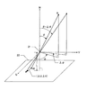
図15に示すように、例えば観測対象物10の1つの表面14が、第1の観測対象物20に対向している。第1の観測装置20から見て横方向を向く表面15に、複数のマーク表示部材11が取り付けられている。マーク表示部材15の各々は、表面15から突出しており、第1の観測装置20に対向する表面を含む。第1の観測装置20に対向する表面に、観測対象マークCが表示されている。
As shown in FIG. 15, for example, one
表面15がW軸に平行である場合、表面15に直接描画したマークを第1の観測装置20で観測することはできない。図15に示したように、表面15から突出したマーク表示部材11を取り付けることにより、表面15に対して固定された観測対象マークCを第1の観測装置20で観測することができる。
When the
図1に示した第2の観測装置30では、図15の表面15に固定された観測対象マークのX軸方向の変位を検出することができない。マーク表示部材11を用いて表面15に固定された観測対象マークCを、第1の観測装置20で観察することにより、観測対象マークCのX軸方向の変位を検出することが可能になる。
The
W軸に直交し、表面15に含まれる方向(図15においてはV軸方向)に関して、マーク表示部材11同士が重ならないように配置することが好ましい。このように配置すると、表面15に固定されたすべての観測対象マークCを第1の観測装置20で観測することができる。
It is preferable to arrange the
W軸方向に関して異なる位置に配置される観測対象マークCのうち、第1の観測装置20の被写界深度内に位置するものは、受像面上に結像させることができる。被写界深度からはずれて受像面上に結像しない場合でも、重心演算等の手法を用いて、観測対象マークCの像の(U,V)座標を検出することができる。
Of the observation target marks C arranged at different positions in the W-axis direction, those located within the depth of field of the
図16に、上記実施例による形状変化測定装置を搭載することができる射出成型機の正面図を示す。射出成型機340が、射出装置350及び型締装置370を含んで構成される。
FIG. 16 shows a front view of an injection molding machine in which the shape change measuring device according to the above embodiment can be mounted. The
射出装置350は、加熱シリンダ351を備え、加熱シリンダ351に、樹脂を供給するホッパ352が配設される。また、加熱シリンダ351内に、スクリュー353が進退自在かつ回転自在に配設される。スクリュー353の後端は、支持部材354によって回転自在に支持される。支持部材354に、サーボモータ等の計量モータ355が駆動部として取り付けられている。計量モータ355の回転が、計量モータ355の出力軸361に取り付けられたタイミングベルト356を介して、被駆動部のスクリュー353に伝達される。計量モータ355の出力軸361の後端に、検出器362が直結している。検出器362は、計量モータ355の回転数または回転量を検出する。検出器362により検出された回転数または回転量に基づいて、スクリュー353の回転速度が求められる。
The
射出装置350はさらに、スクリュー353と平行なねじ軸357を回転自在に備える。ねじ軸357の後端は、サーボモータ等の射出モータ359の出力軸363に取り付けられたタイミングベルト358を介して、射出モータ359に連結されている。従って、射出モータ359によってねじ軸357を回転させることができる。ねじ軸357の前端は支持部材354に固定されたナット360と螺合させられる。駆動部である射出モータ359を駆動し、タイミングベルト358を介して駆動伝達部であるねじ軸357を回転させると、支持部材354が前後進する。
The
支持部材354に、荷重の検出器であるロードセル365が取り付けられている。支持部材354の前後進運動が、ロードセル365を介してスクリュー353に伝えられることにより、スクリュー353が前後進する。ロードセル365により検出された力に対応するデータが、制御装置310に送出される。射出モータ359の出力軸363の後端に、検出器364が直結している。検出器364は、射出モータ359の回転数または回転量を検出する。検出器364により検出された回転数及び回転量に基づいて、スクリュー353の前後進方向の移動速度または前後進方向の位置が求められる。
A
型締装置370は、可動側の金型371が取り付けられた可動プラテン372と、固定側の金型373が取り付けられた固定プラテン374とを含む。可動プラテン372と固定プラテン374とは、タイバー375によって連結される。可動プラテン372はタイバー375に沿って摺動可能である。また、型締装置370は、トグル機構377を含む。トグル機構377は、一端が可動プラテン372と連結し、他端がトグルサポート376と連結する。トグルサポート376の中央において、ボールねじ軸379が回転自在に支持されている。トグル機構377に設けられたクロスヘッド380に固定されたナット381が、ボールねじ軸379に螺合させられている。また、ボールねじ軸379の後端にプーリ382が配設され、サーボモータ等の型締モータ378の出力軸383とプーリ382との間に、タイミングベルト384が架け渡されている。
The
型締装置370において、駆動部である型締モータ378を駆動すると、型締モータ378の回転が、タイミングベルト384を介して、駆動伝達部であるボールねじ軸379に伝達される。そして、ボールねじ軸379及びナット381によって、運動方向が回転運動から直線運動に変換され、トグル機構377が作動させられる。トグル機構377の作動により、可動プラテン372がタイバー375に沿って摺動し、型閉じ、型締め及び型開きが行われる。
In the
型締モータ378の出力軸383の後端に、検出器385が直結している。検出器385は、型締モータ378の回転数または回転量を検出する。検出器385により検出された回転数または回転量に基づいて、ボールねじ軸379の回転に伴って進退するクロスヘッド380の位置、または、トグル機構377によってクロスヘッド380に連結された被駆動部である可動プラテン372の位置が求められる。制御装置310が、計量モータ355、射出モータ359、型締モータ378を制御する。
A
可動側の金型371と固定側の金型373との間に、キャビティcavが形成される。キャビティcavと加熱シリンダ351の内部とが連通している。
A cavity cav is formed between the
型締めを行うと、可動側の金型371及び固定側の金型373に応力が印加され、これらの金型がわずかに変形する。射出成形品の形状の精密度を高めるために、金型のわずかな変形を観測することが望まれる。
When the mold clamping is performed, stress is applied to the
可動側の金型371と固定側の金型373の側面に複数の観測対象マークが固定される。これらの観測対象マークを、上記実施例による形状変化装置を用いて観測することにより、金型の変形の様子を画像により確認することができる。
A plurality of observation target marks are fixed to the side surfaces of the
上記実施例では、観測対象マークAの変位量を検出するための観測装置20。30にディジタルカメラを用いたが、他の方法で変位量を検出してもよい。例えば、レーザ変位計を用いて観測対象マークの変位量を検出することも可能である。
In the above-described embodiment, the digital camera is used for the
以上実施例に沿って本発明を説明したが、本発明はこれらに制限されるものではない。例えば、種々の変更、改良、組み合わせ等が可能なことは当業者に自明であろう。 Although the present invention has been described with reference to the embodiments, the present invention is not limited thereto. It will be apparent to those skilled in the art that various modifications, improvements, combinations, and the like can be made.
10 観測対象物
11 マーク表示部材
20 第1の観測装置
30 第2の観測装置
40 処理装置
41 画像表示装置
42 対象物表示領域
43 操作部
44 経過時間表示バー
45 表示指令部
A、C 観測対象マーク
B 節点
XYZ グローバル座標系
UVW 第1のローカル座標系
RST 第2のローカル座標系
DESCRIPTION OF
Claims (5)
画像を出力する画像出力装置と、
前記第1の観測装置及び前記画像出力装置を制御する制御装置と
を有し、
前記制御装置は、
測定対象物に対応する解析モデルを複数の有限要素に区分し、該有限要素の節点の位置を記憶し、
前記測定対象物上に定義された複数の測定対象マークの位置を記憶し、
前記測定対象マークの各々の位置情報の時刻暦を、前記第1の観測装置から取得し、
前記第1の観測装置から取得した前記位置情報の時刻暦に基づいて、前記節点の各々の変位を算出し、
前記節点の各々の変位に基づいて、前記測定対象物の形状または姿勢の変化を、前記画像出力装置に表示させる形状変化測定装置。 A first observation device that observes the measurement target mark and obtains position information of the measurement target mark;
An image output device for outputting an image;
A control device for controlling the first observation device and the image output device;
The control device includes:
The analysis model corresponding to the measurement object is divided into a plurality of finite elements, and the positions of the nodes of the finite elements are stored.
Storing the positions of a plurality of measurement object marks defined on the measurement object;
Obtaining a time calendar of each position information of the measurement target mark from the first observation device;
Based on the time calendar of the position information acquired from the first observation device, to calculate the displacement of each of the nodes,
A shape change measurement device that displays a change in the shape or posture of the measurement object on the image output device based on the displacement of each of the nodes.
前記制御装置は、
前記第1の観測装置から取得した前記画像データの時刻暦に基づいて、前記受像面内における前記測定対象マークの位置の時刻暦を求め、
前記受像面内における前記測定対象マークの位置の時刻暦から、該測定対象マークの変位の時刻暦を算出し、
前記測定対象マークの変位の時刻暦に基づいて、前記節点の変位の時刻暦を算出する請求項1に記載の形状変化測定装置。 The first observation device includes a lens and an image receiving surface, and outputs image data of an image projected on the image receiving surface via the lens to the control device,
The control device includes:
Based on the time calendar of the image data acquired from the first observation device, obtain the time calendar of the position of the measurement target mark in the image receiving surface,
From the time calendar of the position of the measurement target mark in the image receiving surface, calculate the time calendar of the displacement of the measurement target mark,
The shape change measurement apparatus according to claim 1, wherein a time calendar of displacement of the node is calculated based on a time calendar of displacement of the measurement target mark.
前記制御装置は、
前記受像面上における像の変位を、W軸を基準とした極角の変化量、及びUW平面を基準とした方位角の変化量に換算し、
前記節点の各々の変位を、W軸を基準とした極角の変化量とUV平面を基準とした方位角の変化量とで表し、
前記節点の各々の、W軸を基準とした極角の変化量と、UV平面を基準とした方位角の変化量とに基づいて、該節点の変位を算出する請求項2に記載の形状変化測定装置。 A first local coordinate system by a W axis that coincides with the optical axis of the lens of the first observation apparatus, a U axis and a V axis that pass through the principal point of the lens and are orthogonal to the W axis and orthogonal to each other When defining
The control device includes:
The displacement of the image on the image receiving surface is converted into a change amount of the polar angle with respect to the W axis and a change amount of the azimuth angle with respect to the UW plane,
The displacement of each of the nodes is represented by a change amount of the polar angle with respect to the W axis and a change amount of the azimuth angle with respect to the UV plane,
The shape change according to claim 2, wherein the displacement of the node is calculated based on a change amount of the polar angle with respect to the W axis and a change amount of the azimuth angle with respect to the UV plane of each of the nodes. measuring device.
前記第2の観測装置は、レンズと受像面とを含み、該レンズを介して該受像面上に投影された画像の画像データを前記制御装置に出力し、
前記第2の観測装置の前記レンズの光軸に一致するT軸、該レンズの主点を通過してT軸に直交し、かつ相互に直交するR軸及びS軸により第2のローカル座標系を定義したとき、
前記制御装置は、
前記節点の各々の変位を算出する際に、W軸を基準とした極角の変化量及びUV平面を基準とした方位角の変化量のみならず、T軸を基準とした極角の変化量及びRT平面を基準とした方位角の変化量に基づいて、前記節点の各々の変位を算出する請求項3に記載の形状変化測定装置。 And a second observation device that observes the measurement target mark and obtains position information of the measurement target mark,
The second observation device includes a lens and an image receiving surface, and outputs image data of an image projected on the image receiving surface via the lens to the control device,
A second local coordinate system by a T-axis coinciding with the optical axis of the lens of the second observation device, an R-axis and an S-axis passing through the principal point of the lens and orthogonal to the T-axis and mutually orthogonal When defining
The control device includes:
When calculating the displacement of each of the nodes, not only the change amount of the polar angle based on the W axis and the change amount of the azimuth angle based on the UV plane, but also the change amount of the polar angle based on the T axis. The shape change measuring device according to claim 3, wherein the displacement of each of the nodes is calculated based on a change amount of the azimuth angle with respect to the RT plane.
前記測定対象物に固定された複数の測定対象マークの位置の時刻暦を測定する工程と、
前記測定対象マークの位置の時刻暦に基づいて、前記節点の各々の変位の時刻暦を算出する工程と、
前記節点の各々の変位の時刻暦に基づいて、前記測定対象物の形状の変化を画像として表示する工程と
を有する形状変化測定方法。 Dividing the analysis model corresponding to the measurement object into a plurality of finite elements, and determining the positions of the nodes between the finite elements;
Measuring a time calendar of the position of a plurality of measurement object marks fixed to the measurement object;
Calculating a time calendar of displacement of each of the nodes based on a time calendar of the position of the measurement target mark;
And a step of displaying a change in shape of the measurement object as an image based on a time calendar of displacement of each of the nodes.
Priority Applications (1)
| Application Number | Priority Date | Filing Date | Title |
|---|---|---|---|
| JP2008218317A JP5553493B2 (en) | 2008-08-27 | 2008-08-27 | Shape change measuring apparatus and method |
Applications Claiming Priority (1)
| Application Number | Priority Date | Filing Date | Title |
|---|---|---|---|
| JP2008218317A JP5553493B2 (en) | 2008-08-27 | 2008-08-27 | Shape change measuring apparatus and method |
Publications (2)
| Publication Number | Publication Date |
|---|---|
| JP2010054283A true JP2010054283A (en) | 2010-03-11 |
| JP5553493B2 JP5553493B2 (en) | 2014-07-16 |
Family
ID=42070381
Family Applications (1)
| Application Number | Title | Priority Date | Filing Date |
|---|---|---|---|
| JP2008218317A Expired - Fee Related JP5553493B2 (en) | 2008-08-27 | 2008-08-27 | Shape change measuring apparatus and method |
Country Status (1)
| Country | Link |
|---|---|
| JP (1) | JP5553493B2 (en) |
Cited By (3)
| Publication number | Priority date | Publication date | Assignee | Title |
|---|---|---|---|---|
| JP2013036987A (en) * | 2011-07-08 | 2013-02-21 | Canon Inc | Information processing device and information processing method |
| KR101349541B1 (en) * | 2013-04-15 | 2014-01-08 | 주식회사백상 | Three Dimension Measurement System and Method of Large Component |
| CN115655214A (en) * | 2022-12-26 | 2023-01-31 | 山东省国土空间生态修复中心 | Ground settlement measuring device for exploration and using method |
Citations (8)
| Publication number | Priority date | Publication date | Assignee | Title |
|---|---|---|---|---|
| JPH06186141A (en) * | 1992-12-16 | 1994-07-08 | Hitachi Ltd | Remaining stress prediction method |
| JPH11108630A (en) * | 1997-09-30 | 1999-04-23 | Shiseido Co Ltd | 3d shape measuring method, and method for analyzing distortion and stress on skin surface using the same |
| JP2001025464A (en) * | 1999-05-13 | 2001-01-30 | Shiseido Co Ltd | Method for analyzing individual facial expression deformation process |
| JP2001043402A (en) * | 1999-07-30 | 2001-02-16 | Mitsubishi Electric Corp | Device and method for displaying deformed curved- surface |
| JP2003242485A (en) * | 2002-02-20 | 2003-08-29 | Topcon Corp | Processor and processing method for stereo image |
| JP2005173706A (en) * | 2003-12-08 | 2005-06-30 | Shipbuild Res Assoc Japan | Method and apparatus for shape estimation, and method and apparatus for analytic element generation |
| WO2007010875A1 (en) * | 2005-07-15 | 2007-01-25 | Asahi Glass Company, Limited | Shape inspection method and device |
| JP2007298343A (en) * | 2006-04-28 | 2007-11-15 | Tokyo Institute Of Technology | Method for evaluating welding deformation, and residual stress |
-
2008
- 2008-08-27 JP JP2008218317A patent/JP5553493B2/en not_active Expired - Fee Related
Patent Citations (8)
| Publication number | Priority date | Publication date | Assignee | Title |
|---|---|---|---|---|
| JPH06186141A (en) * | 1992-12-16 | 1994-07-08 | Hitachi Ltd | Remaining stress prediction method |
| JPH11108630A (en) * | 1997-09-30 | 1999-04-23 | Shiseido Co Ltd | 3d shape measuring method, and method for analyzing distortion and stress on skin surface using the same |
| JP2001025464A (en) * | 1999-05-13 | 2001-01-30 | Shiseido Co Ltd | Method for analyzing individual facial expression deformation process |
| JP2001043402A (en) * | 1999-07-30 | 2001-02-16 | Mitsubishi Electric Corp | Device and method for displaying deformed curved- surface |
| JP2003242485A (en) * | 2002-02-20 | 2003-08-29 | Topcon Corp | Processor and processing method for stereo image |
| JP2005173706A (en) * | 2003-12-08 | 2005-06-30 | Shipbuild Res Assoc Japan | Method and apparatus for shape estimation, and method and apparatus for analytic element generation |
| WO2007010875A1 (en) * | 2005-07-15 | 2007-01-25 | Asahi Glass Company, Limited | Shape inspection method and device |
| JP2007298343A (en) * | 2006-04-28 | 2007-11-15 | Tokyo Institute Of Technology | Method for evaluating welding deformation, and residual stress |
Cited By (3)
| Publication number | Priority date | Publication date | Assignee | Title |
|---|---|---|---|---|
| JP2013036987A (en) * | 2011-07-08 | 2013-02-21 | Canon Inc | Information processing device and information processing method |
| KR101349541B1 (en) * | 2013-04-15 | 2014-01-08 | 주식회사백상 | Three Dimension Measurement System and Method of Large Component |
| CN115655214A (en) * | 2022-12-26 | 2023-01-31 | 山东省国土空间生态修复中心 | Ground settlement measuring device for exploration and using method |
Also Published As
| Publication number | Publication date |
|---|---|
| JP5553493B2 (en) | 2014-07-16 |
Similar Documents
| Publication | Publication Date | Title |
|---|---|---|
| JP6407812B2 (en) | Machine tool control system capable of obtaining workpiece origin and workpiece origin setting method | |
| US10775148B2 (en) | Determining a position of a movable part of a coordinate measuring machine | |
| CN109655024B (en) | Method for calibrating external parameters of displacement sensor by adopting space transformation technology | |
| US9915516B2 (en) | Method for controlling shape measuring apparatus | |
| US9335622B2 (en) | Information processing device and information processing system | |
| JP5670416B2 (en) | Robot system display device | |
| EP2499616B1 (en) | Three-dimensional measurement method | |
| JP6053119B2 (en) | Machine vision inspection system and determination method of position measurement result thereof | |
| JP2010145231A (en) | Apparatus and method for measuring displacement of object | |
| US10422629B2 (en) | Method and apparatus for determining a plurality of spatial coordinates on a measurement object | |
| JP5553493B2 (en) | Shape change measuring apparatus and method | |
| KR101078651B1 (en) | System and method for measuring a curved surface | |
| US10697748B2 (en) | Method for controlling shape measuring apparatus | |
| JP5698331B2 (en) | Injection molding machine | |
| JP2010112731A (en) | Joining method of coordinate of robot | |
| JP5203100B2 (en) | Structure analysis apparatus and structure analysis method | |
| JP5473710B2 (en) | Temperature estimation device and analysis device | |
| EP3985347B1 (en) | Device, method and program for measuring point clouds | |
| US11189040B2 (en) | Arrangement and method for capturing a mark arrangement arranged on an object | |
| Tan et al. | Calibration of single-axis nanopositioning cell subjected to thermal disturbance | |
| JP5516974B2 (en) | Vision sensor mounting apparatus and method | |
| JP5610579B2 (en) | 3D dimension measuring device | |
| Sievers et al. | Vision feedback in an automatic nanohandling station inside an SEM | |
| KR20090049720A (en) | Method of the auto calibration for the laser vision system using x-y stage | |
| JP6219030B2 (en) | Processing data generation device and machine tool |
Legal Events
| Date | Code | Title | Description |
|---|---|---|---|
| A621 | Written request for application examination |
Free format text: JAPANESE INTERMEDIATE CODE: A621 Effective date: 20101213 |
|
| A977 | Report on retrieval |
Free format text: JAPANESE INTERMEDIATE CODE: A971007 Effective date: 20120705 |
|
| A131 | Notification of reasons for refusal |
Free format text: JAPANESE INTERMEDIATE CODE: A131 Effective date: 20120710 |
|
| A521 | Written amendment |
Free format text: JAPANESE INTERMEDIATE CODE: A523 Effective date: 20120905 |
|
| A131 | Notification of reasons for refusal |
Free format text: JAPANESE INTERMEDIATE CODE: A131 Effective date: 20130528 |
|
| A521 | Written amendment |
Free format text: JAPANESE INTERMEDIATE CODE: A523 Effective date: 20130725 |
|
| TRDD | Decision of grant or rejection written | ||
| A01 | Written decision to grant a patent or to grant a registration (utility model) |
Free format text: JAPANESE INTERMEDIATE CODE: A01 Effective date: 20140527 |
|
| A61 | First payment of annual fees (during grant procedure) |
Free format text: JAPANESE INTERMEDIATE CODE: A61 Effective date: 20140527 |
|
| R150 | Certificate of patent or registration of utility model |
Ref document number: 5553493 Country of ref document: JP Free format text: JAPANESE INTERMEDIATE CODE: R150 |
|
| LAPS | Cancellation because of no payment of annual fees |