EP3985347B1 - Device, method and program for measuring point clouds - Google Patents
Device, method and program for measuring point clouds Download PDFInfo
- Publication number
- EP3985347B1 EP3985347B1 EP19933509.2A EP19933509A EP3985347B1 EP 3985347 B1 EP3985347 B1 EP 3985347B1 EP 19933509 A EP19933509 A EP 19933509A EP 3985347 B1 EP3985347 B1 EP 3985347B1
- Authority
- EP
- European Patent Office
- Prior art keywords
- measurement
- dimensional data
- dimensional
- sensor
- measurement object
- Prior art date
- Legal status (The legal status is an assumption and is not a legal conclusion. Google has not performed a legal analysis and makes no representation as to the accuracy of the status listed.)
- Active
Links
- 238000000034 method Methods 0.000 title claims description 20
- 238000005259 measurement Methods 0.000 claims description 452
- 230000008859 change Effects 0.000 claims description 42
- 230000033001 locomotion Effects 0.000 claims description 36
- 238000000691 measurement method Methods 0.000 claims description 7
- 230000008569 process Effects 0.000 description 16
- 238000011960 computer-aided design Methods 0.000 description 14
- 238000010586 diagram Methods 0.000 description 10
- 238000006073 displacement reaction Methods 0.000 description 10
- 230000004044 response Effects 0.000 description 5
- 230000009466 transformation Effects 0.000 description 5
- 238000012545 processing Methods 0.000 description 3
- 230000006870 function Effects 0.000 description 2
- 238000003491 array Methods 0.000 description 1
- 230000005540 biological transmission Effects 0.000 description 1
- 238000004140 cleaning Methods 0.000 description 1
- 230000003247 decreasing effect Effects 0.000 description 1
- 230000007547 defect Effects 0.000 description 1
- 230000000694 effects Effects 0.000 description 1
- 230000010365 information processing Effects 0.000 description 1
- 238000007689 inspection Methods 0.000 description 1
- 239000004973 liquid crystal related substance Substances 0.000 description 1
- 239000011159 matrix material Substances 0.000 description 1
- 230000003287 optical effect Effects 0.000 description 1
- 238000010422 painting Methods 0.000 description 1
- 238000005498 polishing Methods 0.000 description 1
- 239000004065 semiconductor Substances 0.000 description 1
- 238000011179 visual inspection Methods 0.000 description 1
- 238000005406 washing Methods 0.000 description 1
Images


Classifications
-
- G—PHYSICS
- G01—MEASURING; TESTING
- G01B—MEASURING LENGTH, THICKNESS OR SIMILAR LINEAR DIMENSIONS; MEASURING ANGLES; MEASURING AREAS; MEASURING IRREGULARITIES OF SURFACES OR CONTOURS
- G01B11/00—Measuring arrangements characterised by the use of optical techniques
- G01B11/002—Measuring arrangements characterised by the use of optical techniques for measuring two or more coordinates
- G01B11/005—Measuring arrangements characterised by the use of optical techniques for measuring two or more coordinates coordinate measuring machines
-
- G—PHYSICS
- G01—MEASURING; TESTING
- G01B—MEASURING LENGTH, THICKNESS OR SIMILAR LINEAR DIMENSIONS; MEASURING ANGLES; MEASURING AREAS; MEASURING IRREGULARITIES OF SURFACES OR CONTOURS
- G01B11/00—Measuring arrangements characterised by the use of optical techniques
- G01B11/24—Measuring arrangements characterised by the use of optical techniques for measuring contours or curvatures
-
- B—PERFORMING OPERATIONS; TRANSPORTING
- B25—HAND TOOLS; PORTABLE POWER-DRIVEN TOOLS; MANIPULATORS
- B25J—MANIPULATORS; CHAMBERS PROVIDED WITH MANIPULATION DEVICES
- B25J13/00—Controls for manipulators
- B25J13/08—Controls for manipulators by means of sensing devices, e.g. viewing or touching devices
- B25J13/088—Controls for manipulators by means of sensing devices, e.g. viewing or touching devices with position, velocity or acceleration sensors
-
- B—PERFORMING OPERATIONS; TRANSPORTING
- B25—HAND TOOLS; PORTABLE POWER-DRIVEN TOOLS; MANIPULATORS
- B25J—MANIPULATORS; CHAMBERS PROVIDED WITH MANIPULATION DEVICES
- B25J19/00—Accessories fitted to manipulators, e.g. for monitoring, for viewing; Safety devices combined with or specially adapted for use in connection with manipulators
- B25J19/02—Sensing devices
- B25J19/021—Optical sensing devices
-
- B—PERFORMING OPERATIONS; TRANSPORTING
- B25—HAND TOOLS; PORTABLE POWER-DRIVEN TOOLS; MANIPULATORS
- B25J—MANIPULATORS; CHAMBERS PROVIDED WITH MANIPULATION DEVICES
- B25J9/00—Programme-controlled manipulators
- B25J9/16—Programme controls
- B25J9/1679—Programme controls characterised by the tasks executed
-
- G—PHYSICS
- G01—MEASURING; TESTING
- G01S—RADIO DIRECTION-FINDING; RADIO NAVIGATION; DETERMINING DISTANCE OR VELOCITY BY USE OF RADIO WAVES; LOCATING OR PRESENCE-DETECTING BY USE OF THE REFLECTION OR RERADIATION OF RADIO WAVES; ANALOGOUS ARRANGEMENTS USING OTHER WAVES
- G01S17/00—Systems using the reflection or reradiation of electromagnetic waves other than radio waves, e.g. lidar systems
- G01S17/88—Lidar systems specially adapted for specific applications
- G01S17/89—Lidar systems specially adapted for specific applications for mapping or imaging
-
- G—PHYSICS
- G06—COMPUTING; CALCULATING OR COUNTING
- G06T—IMAGE DATA PROCESSING OR GENERATION, IN GENERAL
- G06T7/00—Image analysis
- G06T7/30—Determination of transform parameters for the alignment of images, i.e. image registration
-
- G—PHYSICS
- G06—COMPUTING; CALCULATING OR COUNTING
- G06T—IMAGE DATA PROCESSING OR GENERATION, IN GENERAL
- G06T2200/00—Indexing scheme for image data processing or generation, in general
- G06T2200/04—Indexing scheme for image data processing or generation, in general involving 3D image data
-
- G—PHYSICS
- G06—COMPUTING; CALCULATING OR COUNTING
- G06T—IMAGE DATA PROCESSING OR GENERATION, IN GENERAL
- G06T2207/00—Indexing scheme for image analysis or image enhancement
- G06T2207/10—Image acquisition modality
- G06T2207/10028—Range image; Depth image; 3D point clouds
Description
- The present invention relates to a measurement device, a measurement method, and a measurement program.
- In factory automation, a known technique measures multiple point clouds with the three-dimensional (3D) coordinates indicating different points on surfaces of a workpiece from multiple measurement points using, for example, a range sensor. The measurement points are at different positions with respect to the workpiece. A specific point cloud is selected from the multiple measured point clouds as a reference for registration by which the positions and the orientations of the other point clouds are aligned with the position and the orientation of the reference point cloud. The point cloud after the registration is used for workpiece identification. Non-Patent Literature 1 describes registration of multiple point clouds measured at multiple different measurement points.
JP 2007-3285 A - Non-Patent Literature 1: Ryuji Ono, Keiko Ono, 3D Image Recognition Based on Extracted Key Points, The 77th National Convention of Information Processing Society of Japan
- The accuracy of workpiece identification can vary depending on the values of multiple parameters that specify the conditions for measuring each point cloud (e.g., the number of times the point clouds are measured, the time intervals at which the point clouds are measured, the movement distance of the range sensor, the movement speed of the range sensor, the angle at which the range sensor measures the workpiece, the focus range of the range sensor, or the position coordinates of each measurement point). When, for example, the range sensor is moved slower and measures point clouds more times, workpiece identification can be performed with a sufficiently large number of point clouds with sufficiently high quality and thus with improved accuracy. In contrast, when the range sensor is moved faster and measures point clouds more times, workpiece identification is performed with an insufficient number of point clouds with insufficient quality and thus with decreased accuracy. When the range sensor is moved faster, the range sensor may be adjusted to measure point clouds an appropriate number of times. In this case, workpiece identification can be performed with an appropriate number of point clouds with appropriate quality and with relatively improved accuracy. However, when the range sensor is moved slower to improve the accuracy of workpiece identification, the range sensor takes more time to measure point clouds and cannot achieve high productivity aimed in factory automation.
- As described above, the accuracy of workpiece identification or the productivity can vary with different combinations of the values of the parameters specifying the conditions for measuring the point clouds. The relationship remains undefined between a change in each parameter value and the resultant change in the accuracy of workpiece identification or the productivity. The parameters specifying the conditions for measuring the point clouds are to be set to satisfy the conditions intended by the user for measuring point clouds based on the accuracy of workpiece identification or productivity. However, manually setting optimum values for the parameters is not easy.
- In response to the above issue, one or more aspects of the present invention are directed to a measurement device, a measurement method, and a measurement program for outputting values satisfying conditions designated by a user as the values of parameters specifying conditions for obtaining 3D measurement data representing a measurement object.
- A measurement device according to an aspect of the present invention includes a three-dimensional sensor mountable on a robot, a parameter setter, a drive controller, a sensor controller, a registration processor, a functional component configured to perform a comparison, a storage, an input unit, and an output unit. The three-dimensional sensor measures a measurement object to obtain three-dimensional data sets represented by three-dimensional coordinates indicating points on a surface of the measurement object. The parameter setter sets and changes, within a predetermined range, values of a plurality of parameters specifying conditions for obtaining the three-dimensional data sets by measurement. The three-dimensional data sets are obtained by measurement at a plurality of measurement points at which the three-dimensional sensor is at different positions with respect to the measurement object. The three-dimensional data sets include a three-dimensional data set obtained by measurement at a specific measurement point of the plurality of measurement points and a three-dimensional data set obtained by measurement at a measurement point other than the specific measurement point. The three-dimensional data set obtained by measurement at the measurement point other than the specific measurement point is a data set to be registered to the three-dimensional data set obtained by measurement at the specific measurement point. The drive controller outputs, based on the parameter values resulting from the setting or the change, a drive command instructing a driver that drives a joint of the robot to change a position of the three-dimensional sensor with respect to the measurement object. The sensor controller controls, based on the parameter values resulting from the setting or the change, the three-dimensional sensor to measure the measurement object at the plurality of measurement points to obtain the three-dimensional data sets representing the measurement object. The registration processor registers the three-dimensional data set obtained by measurement at the measurement point other than the specific measurement point to the three-dimensional data set obtained by measurement at the specific measurement point to obtain three-dimensional data. The functional component configured to perform a comparison compares the three-dimensional data obtained by the registration processor with 3D CAD data representing the measurement object to obtain an identification result. The storage stores the identification result in association with the parameter values resulting from the setting or the change. The input unit receives, from a user, designation of a priority condition for obtaining three-dimensional data by measurement. The output unit outputs one or more combinations of values of parameters satisfying the priority condition based on association between identification results of the measurement object and the parameter values resulting from the setting or the change. The one or more combinations are arranged in order of a higher degree of satisfying the priority condition. The user simply selects one of the combinations of the values of the parameters output as combinations that satisfy the priority condition designated by the user. This eliminates complicated manual adjustment of the parameters. The user can thus easily and rapidly set the parameters satisfying the priority condition designated by the user without complicated parameter adjustment.
- The plurality of parameters specifying the conditions for obtaining the three-dimensional data sets by measurement may include at least one parameter selected from the group consisting of the number of times measurement is performed to obtain the three-dimensional data sets, a movement distance of the three-dimensional sensor, a movement speed of the three-dimensional sensor, time intervals at which measurement is performed to obtain the three-dimensional data sets, an angle at which the three-dimensional sensor measures the measurement object, a focus range of the three-dimensional sensor, and position coordinates of each of the plurality of measurement points. Setting the above parameters allows customization of the conditions for obtaining 3D measurement data to satisfy the priority condition designated by the user.
- The predetermined range of values for each parameter specifying the conditions for obtaining the three-dimensional data sets by measurement may be estimated to satisfy the priority condition designated by the user using the input unit. Narrowing the predetermined range of values for each parameter specifying the conditions for obtaining 3D measurement data to a range of values estimated to satisfy the priority condition designated by the user reduces the number of measurement processes for 3D data and the number of registration processes for parameter setting, thus allowing easy and rapid setting of the parameters satisfying the priority condition designated by the user.
- A measurement method according to another aspect of the present invention is implementable by a measurement device including a three-dimensional sensor mountable on a robot. The three-dimensional sensor measures a measurement object to obtain three-dimensional data sets represented by three-dimensional coordinates indicating points on a surface of the measurement object. The measurement method includes setting and changing values, outputting a drive command, controlling the three-dimensional sensor, registering the three-dimensional data sets, storing an identification result, comparing three-dimensional data with 3D CAD data, receiving designation, and outputting one or more combinations. The setting and changing the values includes setting and changing, within a predetermined range, values of a plurality of parameters specifying conditions for obtaining the three-dimensional data sets by measurement. The three-dimensional data sets are obtained by measurement at a plurality of measurement points at which the three-dimensional sensor is at different positions with respect to the measurement object. The three-dimensional data sets include a three-dimensional data set obtained by measurement at a specific measurement point of the plurality of measurement points and a three-dimensional data set obtained by measurement at a measurement point other than the specific measurement point. The three-dimensional data set obtained by measurement at the measurement point other than the specific measurement point is a data set to be registered to the three-dimensional data set obtained by measurement at the specific measurement point. The outputting the drive command includes outputting, based on the parameter values resulting from the setting or the change, a drive command instructing a driver that drives a joint of the robot to change a position of the three-dimensional sensor with respect to the measurement object. The controlling the three-dimensional sensor includes controlling, based on the parameter values resulting from the setting or the change, the three-dimensional sensor to measure the measurement object at the plurality of measurement points to obtain the three-dimensional data sets representing the measurement object. The registering the three-dimensional data sets includes registering the three-dimensional data set obtained by measurement at the measurement point other than the specific measurement point to the three-dimensional data set obtained by measurement at the specific measurement point to obtain three-dimensional data. The comparing three-dimensional data with 3D CAD data comprises comparing the three-dimensional data obtained through said registering with 3D CAD data representing the measurement object to obtain an identification result. The storing the identification result includes storing the identification result in association with the parameter values resulting from the setting or the change. The receiving the designation includes receiving, from a user, designation of a priority condition for obtaining three-dimensional data by measurement. The outputting one or more combinations includes outputting one or more combinations of values of parameters satisfying the priority condition based on association between identification results of the measurement object and the parameter values resulting from the setting or the change. The one or more combinations are arranged in order of a higher degree of satisfying the priority condition. The user simply selects one of the combinations of the values of the parameters output as combinations that satisfy the priority condition designated by the user. This eliminates complicated manual adjustment of the parameters. The user can thus easily and rapidly set the parameters satisfying the priority condition designated by the user without complicated parameter adjustment.
- A measurement program according to another aspect of the present invention is a program executable by a measurement device including a three-dimensional sensor mountable on a robot. The three-dimensional sensor measures a measurement object to obtain three-dimensional data sets represented by three-dimensional coordinates indicating points on a surface of the measurement object. The measurement program is executable by the measurement device to perform operations including setting and changing values, outputting a drive command, controlling the three-dimensional sensor, registering the three-dimensional data sets, comparing three-dimensional data with 3D CAD data, storing an identification result, receiving designation, and outputting one or more combinations. The setting and changing the values includes setting and changing, within a predetermined range, values of a plurality of parameters specifying conditions for obtaining the three-dimensional data sets by measurement. The three-dimensional data sets are obtained by measurement at a plurality of measurement points at which the three-dimensional sensor is at different positions with respect to the measurement object. The three-dimensional data sets include a three-dimensional data set obtained by measurement at a specific measurement point of the plurality of measurement points and a three-dimensional data set obtained by measurement at a measurement point other than the specific measurement point. The three-dimensional data set obtained by measurement at the measurement point other than the specific measurement point is a data set to be registered to the three-dimensional data set obtained by measurement at the specific measurement point. The outputting the drive command includes outputting, based on the parameter values resulting from the setting or the change, a drive command instructing a driver that drives a joint of the robot to change a position of the three-dimensional sensor with respect to the measurement object. The controlling the three-dimensional sensor includes controlling, based on the parameter values resulting from the setting or the change, the three-dimensional sensor to measure the measurement object at the plurality of measurement points to obtain the three-dimensional data sets representing the measurement object. The registering the three-dimensional data sets includes registering the three-dimensional data set obtained by measurement at the measurement point other than the specific measurement point to the three-dimensional data set obtained by measurement at the specific measurement point to obtain three-dimensional data. The comparing three-dimensional data with 3D CAD data comprises comparing the three-dimensional data obtained through said registering with 3D CAD data representing the measurement object to obtain an identification result. The storing the identification result includes storing the identification result in association with the parameter values resulting from the setting or the change. The receiving the designation includes receiving, from a user, designation of a priority condition for obtaining three-dimensional data by measurement. The outputting one or more combinations includes outputting one or more combinations of values of parameters satisfying the priority condition based on association between identification results of the measurement object and the parameter values resulting from the setting or the change. The one or more combinations are arranged in order of a higher degree of satisfying the priority condition. The user simply selects one of the combinations of the values of the parameters output as combinations that satisfy the priority condition designated by the user. This eliminates complicated manual adjustment of the parameters. The user simply selects one of the combinations of the values of the parameters output as combinations that satisfy the priority condition designated by the user. This eliminates complicated manual adjustment of the parameters. The user can thus easily and rapidly set the parameters satisfying the priority condition designated by the user without complicated parameter adjustment.
- The technique according to the above aspects of the present invention allows the values of the parameters specifying the conditions for obtaining the 3D measurement data representing a measurement object to be output as values that satisfy the condition designated by the user.
-
-
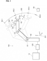
FIG. 1 is a diagram of a measurement system in an embodiment of the present invention showing its overall structure. -
FIG. 2 is a diagram describing a sequence of 3D data registration in the -
FIG. 3 is a block diagram of the measurement system and a measurement device in the embodiment of the present invention showing the hardware configuration. -
FIG. 4 is a diagram describing a process of associating an identification result of a measurement object for each of all possible combinations of values of multiple parameters specifying conditions for obtaining 3D measurement data with the parameter values in the embodiment of the present invention. -
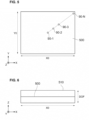
FIG. 5 is a diagram describing the process of associating an identification result of the measurement object for each of all possible combinations of values of multiple parameters specifying conditions for obtaining 3D measurement data with the parameter values in the embodiment of the present invention. -
FIG. 6 is a diagram describing the process of associating an identification result of the measurement object for each of all possible combinations of values of multiple parameters specifying conditions for obtaining 3D measurement data with the parameter values in the embodiment of the present invention. -
FIG. 7 is a flowchart of an example process of associating an identification result of the measurement object for each of all possible combinations of values of multiple parameters specifying conditions for obtaining 3D measurement data with the parameter values in the embodiment of the present invention. -
FIG. 8 is a graph showing example identification results of the measurement object in the embodiment of the present invention. -
FIG. 9 is a flowchart of a process of outputting one or more combinations of the values of the parameters satisfying a priority condition for obtaining 3D measurement data in the embodiment of the present invention. -
FIG. 10 is a functional block diagram of a computer system in the embodiment of the present invention. - One or more embodiments according to one aspect of the present invention will now be described with reference to the drawings. The embodiments are described for easy understanding of the present invention and do not limit the present invention. The present invention may be modified or improved without departing from the scope of the present invention, which is defined by the appended claims. The present invention covers the equivalents that fall within the scope of the present invention. The same components are given the same reference numerals, and will not be described repeatedly.
-
FIG. 1 is a diagram of ameasurement system 100 in an embodiment of the present invention showing its overall structure. Themeasurement system 100 includes arobot 60, a three-dimensional (3D)sensor 70 mounted on therobot 60, acomputer system 10 that controls driving of therobot 60 and measurement for 3D data representing ameasurement object 80 performed by the3D sensor 70, and arobot controller 120 that controls the motion of therobot 60 in response to a command from thecomputer system 10. - The 3D data is represented by the 3D coordinates indicating points on surfaces of the
measurement object 80. For example, the 3D data may include a point cloud or a range image. A point cloud is, for example, a set of points each having 3D coordinates (x, y, z) in an orthogonal xyz coordinate system. A range image is, for example, a set of pixels each having a pixel value indicating a distance d corresponding to two-dimensional (2D) image coordinates (u, v) in an orthogonal uv coordinate system. The distance d is a distance between the3D sensor 70 and themeasurement object 80. - The
3D sensor 70 may be a range sensor that measures a point cloud or a range image sensor combining a range sensor and a 2D sensor to obtain a range image. The range sensor measures the distance d as depth information. The range sensor may use, for example, trigonometry, time of flight, or a phase difference in measurement. The 2D sensor is an image sensor that captures a 2D image. A 2D image differs from a range image in not using the distance d as its pixel value. The range image sensor may be, for example, a camera that captures multiple 2D images of themeasurement object 80 with the 2D sensor changing its position, and obtains a range image having pixel values indicating the distances d through stereoscopic image processing. In another example, the range image sensor may be a stereo camera that captures multiple images of themeasurement object 80 in different directions at a time to obtain a range image that has pixel values indicating the distances d. - The
robot 60 is, for example, an articulated robot (e.g., a vertical articulated robot or a horizontal articulated robot) with arobot hand 63 for manipulating (e.g., gripping, sucking, moving, assembling, or inserting) themeasurement object 80. Therobot 60 includesdrivers 61 for driving the joints anddisplacement detectors 62 for detecting displacement (angular displacement) of the joints. Thedrivers 61 are, for example, servomotors that are driven in response to a drive command from therobot controller 120. Thedisplacement detectors 62 are, for example, encoders (e.g., incremental encoders or absolute encoders) that detect the rotation angles of the servomotors. Therobot 60 incorporates, at each joint, thedriver 61 and thedisplacement detector 62. - The
robot 60 operates as an autonomous manipulator in various tasks such as picking, assembling, transporting, painting, inspecting, polishing, and washing themeasurement object 80. Themeasurement object 80 is, for example, a workpiece or a part. Examples of workpieces include mechanical parts for powertrain systems of automobiles (e.g., engines and transmissions) and electronic parts for electrical systems. - The
measurement system 100 controls the driving of each joint of therobot 60 to change the position of the3D sensor 70 with respect to themeasurement object 80. Themeasurement system 100 measures themeasurement object 80 at multiple measurement points 90-1, 90-2, and 90-3 to 90-N with the3D sensor 70 at the corresponding different positions to obtain 3D measurement data, where N is an integer greater than or equal to 2. For example, themeasurement system 100 may obtain, at one or more specific measurement points of the multiple measurement points 90-1, 90-2, and 90-3 to 90-N, 3D data representing themeasurement object 80 by measurement while therobot 60 is stopped and may obtain, at each measurement points other than the specific measurement points, 3D data representing themeasurement object 80 by measurement while therobot 60 is in motion. For example, themeasurement system 100 may measure 3D data representing themeasurement object 80 at all the measurement points 90-1, 90-2, and 90-3 to 90-N while therobot 60 is stopped. - In
FIG. 1 , a coordinatesystem 201 is defined with respect to therobot 60, a coordinatesystem 202 is defined with respect to therobot hand 63, and a coordinatesystem 203 is defined with respect to the3D sensor 70. The coordinatesystem 201 is referred to as a robot coordinate system, the coordinatesystem 202 as a tool coordinate system, and the coordinatesystem 203 as a sensor coordinate system. -
FIG. 2 is a diagram describing a sequence of 3D data registration in the embodiment of the present invention. Registration refers to coordinate transformation for aligning the position and the orientation of one 3D data set with the position and the orientation of another 3D data set. 3D data sets 150-1, 150-2, and 150-3 to 150-N are sets of 3D data representing themeasurement object 80 measured at the measurement points 90-1, 90-2, and 90-3 to 90-N. The measurement point 90-1 may be selected as a specific measurement point from the measurement points 90-1, 90-2, and 90-3 to 90-N. The 3D measurement data sets 150-2, 150-3 to 150-N obtained at the measurement points 90-2, 90-3 to 90-N other than at the specific measurement point 90-1 may each be registered to the 3D measurement data 150-1 obtained at the specific measurement point 90-1 to obtain 3D data 150-S. Any of the 3D data sets other than the 3D data 150-1 may be used as a reference for registration of the other 3D data sets. - For example, iterative closest point (ICP) may be used as a registration algorithm. For each point in one 3D data set, ICP identifies the closest point in another 3D data set and tentatively determines the closest point as a corresponding point. ICP estimates a rigid transformation that minimizes the distance between each pair of corresponding points and iterates the identification of corresponding points and the estimation of a rigid transformation to minimize the distance between each pair of corresponding points in the 3D data sets. Before execution of ICP, a known algorithm may be used to estimate the corresponding points based on the features of 3D data. Such a known algorithm may use, for example, a point pair feature (PPF).
- An example hardware configuration of the
measurement system 100 and ameasurement device 200 in the embodiment of the present invention will now be described with reference toFIG. 3 . - The
measurement device 200 includes thecomputer system 10 and the3D sensor 70. Themeasurement system 100 includes themeasurement device 200, therobot 60, and therobot controller 120. Thecomputer system 10 includes anarithmetic unit 20, astorage 30, an input-output interface 40, and adisplay interface 50. Thearithmetic unit 20 includes a central processing unit (CPU) 21, a read-only memory (ROM) 22, and a random-access memory (RAM) 23. The input-output interface 40 is connected to the3D sensor 70, therobot controller 120, and aninput device 130. Theinput device 130 is, for example, a keyboard, a mouse, or a touchpad. Thedisplay interface 50 is connected to adisplay 140. Thedisplay 140 is, for example, a liquid crystal display. - The
storage 30 is a computer-readable recording medium, such as a disk medium (e.g., a magnetic recording medium or a magneto-optical recording medium) or a semiconductor memory (e.g., a volatile memory or a nonvolatile memory). Such a recording medium may be referred to as, for example, a nontransitory recording medium. Thestorage 30 stores ameasurement program 31 for implementing a measurement method according to the embodiment of the present invention. Themeasurement program 31 is read into theRAM 23 from thestorage 30 and interpreted and executed by theCPU 21. Themeasurement program 31 also functions as a main program for controlling the motion of therobot 60. Thestorage 30 also stores 3D computer-aided design (CAD)data 32 representing themeasurement object 80. - The
arithmetic unit 20 receives, through the input-output interface 40, an input of information indicating the displacement of each joint of therobot 60 output from thedisplacement detector 62 and outputs a drive command to eachdriver 61 that drives the a corresponding joint of therobot 60. - The
robot controller 120 controls, in response to the drive command output from thearithmetic unit 20 through the input-output interface 40, driving of each driver 61 (e.g., the number of rotations and the torque of the servomotor) that drives the joint of therobot 60. - The
3D sensor 70 measures, in response to a measurement command output from thearithmetic unit 20 through the input-output interface 40, themeasurement object 80 to obtain 3D data sets 150-1, 150-2, and 150-3 to 150-N for themeasurement object 80. - The
arithmetic unit 20 outputs, through the input-output interface 40, the measurement command to instruct the3D sensor 70 to obtain the 3D measurement data sets 150-1, 150-2, and 150-3 to 150-N for themeasurement object 80 and the drive command for controlling the driving of thedrivers 61. Thearithmetic unit 20 also receives inputs of the 3D data sets 150-1, 150-2, and 150-3 to 150-N for themeasurement object 80 measured by the3D sensor 70. TheRAM 23 temporarily stores the 3D data sets 150-1, 150-2, and 150-3 to 150-N for themeasurement object 80 measured by the3D sensor 70 and functions as a work area for registration performed by thearithmetic unit 20. Thearithmetic unit 20 compares the 3D data 150-S resulting from the registration with the3D CAD data 32 representing themeasurement object 80 to identify themeasurement object 80. Thearithmetic unit 20 may transform the coordinates representing the 3D data 150-S in the sensor coordinatesystem 203 to the coordinates in the robot coordinatesystem 201 using a known transformation matrix and estimate the position and the orientation of themeasurement object 80 with respect to therobot 60. - The
display 140 shows the results of various processes (e.g., an identification result of the measurement object 80) performed with themeasurement program 31. - Although the
robot 60 includes asingle driver 61 and asingle displacement detector 62 in the example shown inFIG. 3 , therobot 60 may include asmany drivers 61 anddisplacement detectors 62 as the joints. - The process of associating a result from identifying the
measurement object 80 for each of all possible combinations of the values of parameters specifying conditions for obtaining 3D measurement data with the parameter values will now be described with reference toFIGs. 4 to 9 . 3D measurement data representing themeasurement object 80 may be obtained at one or more specific measurement points of the measurement points 90-1, 90-2, and 90-3 to 90-N while therobot 60 is stopped, and 3D measurement data representing themeasurement object 80 may be obtained at each measurement point other than the specific measurement points while therobot 60 is in motion. In this case, the parameters may include, for example, at least one selected from the group consisting of the number of times the measurement is performed to obtain the 3D data representing themeasurement object 80, the movement distance of the3D sensor 70, the angle at which the3D sensor 70 measures themeasurement object 80, the focus range of the3D sensor 70, the movement speed of the3D sensor 70, and the time intervals at which the measurement is performed to obtain 3D data representing themeasurement object 80. 3D measurement data representing themeasurement object 80 may be obtained while therobot 60 is stopped at all the measurement points 90-1, 90-2, and 90-3 to 90-N. In this case, the parameters may include, for example, at least one selected from the group consisting of the number of times the measurement is performed to obtain 3D data representing themeasurement object 80, the movement distance of the3D sensor 70, the angle at which the3D sensor 70 measures themeasurement object 80, the focus range of the3D sensor 70, and the position coordinates of each of the measurement points 90-1, 90-2, and 90-3 to 90-N. The focus range of the3D sensor 70 refers to the depth of field. - As shown in
FIG. 4 , thearithmetic unit 20 defines an orthogonal XYZ coordinate system including an XY plane, which is parallel to the placement surface of acontainer 160 containing randomly placed measurement objects 80, and Z-direction, which is perpendicular to the placement surface of thecontainer 160. Thecontainer 160 has a length X0 in X-direction and a length Y0 in Y-direction. The3D sensor 70 is located with respect to eachmeasurement object 80 to satisfy the condition for achieving the best focus at a distance Z0 from themeasurement object 80. - As shown in
FIG. 5 , thearithmetic unit 20 defines aplane 500 that defines a range in which the3D sensor 70 is movable in X- and Y-directions. Theplane 500 is a projection plane obtained by projecting the planar shape of thecontainer 160 viewed in Z-direction onto the plane of Z = Z0. Theplane 500 has a length in X-direction equal to the length X0 and a length in Y-direction equal to Y0. - As shown in
FIG. 6 , thearithmetic unit 20 sets a range of depth of field (DOF) in Z-direction in which the3D sensor 70 is located with respect to eachmeasurement object 80 to satisfy the condition for achieving focus. Thearithmetic unit 20 defines a3D space 510 within the range of DOF from theplane 500 as a space defining the range in which the3D sensor 70 is movable in X-, Y-, and Z-directions. The DOF herein corresponds to the depth of field of the3D sensor 70. The position coordinates of the measurement points 90-1, 90-2, and 90-3 to 90-N of the3D sensor 70 are all within the3D space 510. - The
arithmetic unit 20 obtains the 3D data sets 150-1, 150-2, and 150-3 to 150-N by measurement while randomly changing, within a predetermined range, the values of the parameters that specify the conditions for obtaining each of the 3D measurement data sets 150-1, 150-2, and 150-3 to 150-N, with each of the measurement points 90-1, 90-2, and 90-3 to 90-N of the3D sensor 70 at position coordinates within the3D space 510. Thearithmetic unit 20 compares the 3D data 150-S obtained through registration of the 3D data sets 150-1, 150-2, and 150-3 to 150-N with the3D CAD data 32 representing themeasurement object 80 and stores the identification result (success or failure of the identification) of eachmeasurement object 80 into thestorage 30 in a manner associated with a corresponding combination of the parameter values. The range of possible values for each parameter may be set by default based on, for example, the performance or specifications of the3D sensor 70 and therobot 60 to practically allow measurement for the 3D data representing themeasurement object 80. The range of possible values for each parameter may be estimated to satisfy a priority condition designated by the user for obtaining the 3D measurement data. The priority condition will be described in detail later. - As shown in
FIG. 5 , thearithmetic unit 20 may set, for example, the measurement point 90-1 at the center of theplane 500 from which the3D sensor 70 starts measurement to obtain 3D data, the measurement point 90-N on an edge of theplane 500 at which the3D sensor 70 ends the 3D measurement, and the other measurement points 90-2 and 90-3 to 90-(N-1) on the straight line connecting the two measurement points 90-1 and 90-N. In this case, the distance between the measurement points 90-1 and 90-N is equal to the movement distance of the3D sensor 70. When the movement speed of the3D sensor 70 is constant, the movement time of the3D sensor 70 can be calculated based on the movement distance and the movement speed of the3D sensor 70. When the time intervals for obtaining the 3D measurement data are constant, the number of times the measurement is performed to obtain 3D data can be calculated based on the movement time of the3D sensor 70 and the measurement time intervals. The angle at which the3D sensor 70 measures themeasurement object 80 is the angle at which a line segment passing through the3D sensor 70 and themeasurement object 80 intersects with a predetermined reference line (e.g., a horizontal line or a vertical line). - For example, the
arithmetic unit 20 fixes the movement speed of the3D sensor 70 at a constant speed, successively changes the time intervals for obtaining the 3D measurement data from an upper end to a lower end of a predetermined range while the3D sensor 70 is moving at the fixed speed, and obtains the 3D measurement data representing themeasurement object 80 by the number of times calculated based on each time interval at which the measurement is performed to obtain 3D data. Thearithmetic unit 20 iterates such a process while successively changing the movement speed of the3D sensor 70 from an upper end to a lower end of a predetermined range. In this manner, thearithmetic unit 20 obtains multiple sets of 3D measurement data representing eachmeasurement object 80 while successively changing the movement speed of the3D sensor 70 and the number of times the measurement is performed to obtain 3D data from the upper end to the lower end, compares the 3D data 150-S obtained through registration of the multiple 3D data sets with the3D CAD data 32 representing themeasurement object 80, and stores the identification result (success or failure of the identification) of themeasurement object 80 into thestorage 30 in a manner associated with the corresponding combination of the parameter values. - Each of the measurement points 90-1, 90-2, and 90-3 to 90-N may be at any position coordinates within the
3D space 510, other than at the example coordinates shown inFIG. 5 . The measurement points 90-1, 90-2, and 90-3 to 90-N may be at position coordinates at which the3D sensor 70 measures themeasurement object 80 at different angles. The3D sensor 70 may move along a curve or a combination of a straight line and a curve, rather than along a straight line. -
FIG. 7 is a flowchart of an example process of associating an identification result of themeasurement object 80 for each of all possible combinations of the values of the parameters specifying the conditions for obtaining the 3D measurement data with the corresponding parameter values. - In
step 701, thearithmetic unit 20 defines, based on the values X0, Y0, and Z0 described above, the3D space 510 that defines the range in which the3D sensor 70 is movable in X-, Y-, and Z-directions. - In
step 702, thearithmetic unit 20 sets, based on information for the3D space 510 defined instep 701, the values of the parameters specifying the conditions for obtaining the 3D measurement data representing themeasurement object 80 within a predetermined range. - In
step 703, thearithmetic unit 20 outputs, based on the parameter values set in step 702 (or changed instep 707 described later), a drive command for instructing thedrivers 61 that drive the joints of therobot 60 to change the position of the3D sensor 70 with respect to themeasurement object 80 and outputs a measurement command for instructing the3D sensor 70 to measure themeasurement object 80 to obtain the 3D data sets 150-1, 150-2, and 150-3 to 150-N for themeasurement object 80 at the measurement points 90-1, 90-2, and 90-3 to 90-N. - In
step 704, thearithmetic unit 20 registers the 3D data sets 150-1, 150-2, and 150-3 to 150-N obtained instep 703 to obtain the 3D data 150-S. - In
step 705, thearithmetic unit 20 compares the 3D data 150-S obtained through the registration performed instep 704 with the3D CAD data 32 representing themeasurement object 80 and stores the identification result (success or failure of the identification) of themeasurement object 80 into thestorage 30 in a manner associated with the combination of the parameter values set instep 702. - In
step 706, thearithmetic unit 20 determines whether the processing insteps 703 to 705 has been performed on all possible combinations of the values of the parameters that specify the conditions for obtaining the 3D measurement data representing themeasurement object 80. - In
step 707, thearithmetic unit 20 changes the values of the parameters specifying the conditions for obtaining the 3D measurement data representing themeasurement object 80 within a predetermined range. -
FIG. 8 is a graph showing example identification results of themeasurement object 80. This 3D graph shows the successful identification count of themeasurement object 80 against the movement speed of the3D sensor 70 and the number of times the measurement is performed to obtain 3D data. The successful identification count of themeasurement object 80 refers to the number of times identification of themeasurement object 80 has been successful out of the total number of times the measurement is performed to obtain 3D data. The movement speeds of 20%, 40%, 60%, 80%, and 100% of the3D sensor 70 each indicate the ratio of the movement speed of the3D sensor 70 to a predetermined speed. -
FIG. 9 is a flowchart of a process of outputting one or more combinations of the values of parameters satisfying a priority condition for obtaining the 3D measurement data sets 150-1, 150-2, and 150-3 to 150-N. - In
step 901, thearithmetic unit 20 performs, for all combinations of the parameter values within a range of possible values for each parameter specifying the conditions for obtaining the 3D measurement data representing themeasurement object 80, measurement for multiple 3D data sets, registration of the obtained 3D measurement data sets, identification of themeasurement object 80 based on the 3D data 150-S obtained through the registration, and association of the identification result of themeasurement object 80 with the parameter values. These processes are the same as the processes performed insteps 701 to 707 in the flowchart shown inFIG. 7 . - In
step 902, thearithmetic unit 20 receives designation of a priority condition for obtaining the 3D measurement data representing themeasurement object 80 from the user. The user can operate theinput device 130 to input the priority condition for obtaining the 3D measurement data into thecomputer system 10. The user may designate, for example, the maximum successful identification count for themeasurement object 80 as a priority condition for obtaining the 3D measurement data. The user may designate, for example, the average successful identification count or more than the average successful identification count for themeasurement object 80 and the shortest time for obtaining the 3D measurement data representing themeasurement object 80 as priority conditions for obtaining the 3D measurement data. The user may designate, for example, the average successful identification count or more than the average successful identification count for themeasurement object 80 and the highest movement speed of the3D sensor 70 as priority conditions for obtaining the 3D measurement data. The user may designate, for example, a well-balanced relationship between the successful identification count of themeasurement object 80, the time taken for obtaining the 3D measurement data representing themeasurement object 80, and the movement speed of the3D sensor 70 as a priority condition for obtaining the 3D measurement data. - In
step 903, thearithmetic unit 20 outputs to, for example, thedisplay 140, one or more combinations of the values of the parameters satisfying the priority condition designated by the user. The combinations are arranged in order of a higher degree of satisfying the priority condition based on the association between the values of the parameters specifying the conditions for obtaining the 3D measurement data and the identification results of themeasurement object 80. In this case, thearithmetic unit 20 may output the highest-order M combinations with a high degree of satisfying the priority condition selected from all combinations of the parameter values, where M is an integer greater than or equal to 2. Thearithmetic unit 20 may output a single optimum combination of the values of the parameters satisfying the priority condition designated by the user. - The order of
steps step 902 before the process instep 901, thearithmetic unit 20 may narrow, insteps measurement object 80 to the range of values for each parameter satisfying the priority condition designated by the user for obtaining the 3D measurement data. For example, the user may designate the average successful identification count or more than the average successful identification count of themeasurement object 80 and the highest movement speed of the3D sensor 70 as priority conditions for obtaining the 3D measurement data. In this case, thearithmetic unit 20 may narrow the range of possible values for each parameter specifying the conditions for obtaining the 3D measurement data to the range of parameter values that allow the3D sensor 70 to move at a predetermined speed or higher. -
FIG. 10 is a functional block diagram of thecomputer system 10 in the embodiment of the present invention. Thecomputer system 10 includes the hardware resources (thearithmetic unit 20, thestorage 30, and the input-output interface 40) that operate in cooperation with themeasurement program 31 to implement the functional components including aparameter setter 101, adrive controller 102, asensor controller 103, aregistration processor 104, astorage 105, aninput unit 106, anoutput unit 107, a coordinatetransformer 108, a position-orientation estimator 109, and amotion target calculator 110. - The
parameter setter 101 sets and changes, within a predetermined range (e.g., a default range or a range of parameter values estimated to satisfy the priority condition designated by the user for obtaining 3D measurement data), the values of the parameters specifying the conditions for obtaining 3D measurement data sets for the measurement objects 80 (steps FIG. 7 ). The 3D measurement data sets are obtained at the measurement points 90-1, 90-2, and 90-3 to 90-N at which the3D sensor 70 is at different positions with respect to themeasurement object 80. The 3D measurement data sets include a 3D data set for themeasurement object 80 obtained at a specific measurement point of the measurement points and a 3D measurement data set for themeasurement object 80 obtained at each of measurement points other than the specific measurement point. The 3D measurement data set obtained at each measurement point other than the specific measurement point is to be registered to the 3D measurement data set obtained at the specific measurement point. - The
drive controller 102 outputs, for each change of the value of at least one of the parameters specifying the conditions for obtaining each 3D measurement data set, a drive command instructing thedrivers 61 that drive the joints of therobot 60 to change, based on the parameter values resulting from the change, the position of the3D sensor 70 with respect to the measurement object 80 (step 703 inFIG. 7 ). - The
sensor controller 103 controls, for each change of the value of at least one of the parameters specifying the conditions for obtaining each 3D measurement data set, the3D sensor 70 to measure themeasurement object 80 to obtain the 3D data sets 150-1, 150-2, and 150-3 to 150-N for themeasurement object 80 at the measurement points 90-1, 90-2, and 90-3 to 90-N based on the parameter values resulting from the change (step 703 inFIG. 7 ). - The
registration processor 104 registers, for each change of the value of at least one of the parameters specifying the conditions for obtaining each 3D measurement data set, the 3D measurement data obtained at each measurement point other than a specific measurement point to the 3D measurement data obtained at the specific measurement point (step 704 inFIG. 7 ). - The
storage 105 stores, for each change of the value of at least one of the parameters specifying the conditions for obtaining each 3D measurement data set, the identification result of themeasurement object 80 based on the 3D data 150-S obtained through the registration in association with parameter values (step 705 inFIG. 7 ). - The
input unit 106 receives designation of a priority condition for obtaining the 3D measurement data from the user (step 902 inFIG. 9 ). - The
output unit 107 outputs to, for example, thedisplay 140, one or more combinations of the values of the parameters satisfying the priority condition designated by the user based on the association between the identification results of themeasurement object 80 and the values of the parameters specifying the conditions for obtaining each 3D measurement data set. The combinations are arranged in order of a higher degree of satisfying the priority condition (step 903 inFIG. 9 ). The user can select, from the combination(s) of the values of the parameters satisfying the priority condition, any one combination of parameter values by operating theinput device 130. Theparameter setter 101 sets the values of the parameters specifying the condition for obtaining each 3D measurement data set based on the user selection. - The
measurement system 100 controls therobot 60 and the3D sensor 70 based on the combination of the parameter values selected by the user from the combinations of values of the parameters satisfying the priority condition specified by the user to obtain the 3D measurement data sets 150-1, 150-2, and 150-3 to 150-N for themeasurement object 80. Themeasurement system 100 registers the 3D data sets 150-1, 150-2, and 150-3 to 150-N to obtain the 3D data 110-S. - The coordinate
transformer 108 transforms the coordinates representing the 3D data 110-S in the sensor coordinatesystem 203 to the coordinates in the robot coordinatesystem 201. - The position-
orientation estimator 109 estimates the position and the orientation of themeasurement object 80 with respect to therobot 60 based on the 3D data defined in the robot coordinatesystem 201 resulting from the coordinate transformation performed by the coordinatetransformer 108. - The
motion target calculator 110 calculates motion targets for therobot 60 to manipulate themeasurement object 80 based on the position and the orientation of themeasurement object 80 with respect to therobot 60. The motion targets include a target position and a target orientation of therobot 60 to manipulate (e.g., grip, suck, move, assemble, or insert) themeasurement object 80. - The components described above (the
parameter setter 101, thedrive controller 102, thesensor controller 103, theregistration processor 104, thestorage 105, theinput unit 106, theoutput unit 107, the coordinatetransformer 108, the position-orientation estimator 109, and the motion target calculator 110) may be implemented by, for example, dedicated hardware resources (e.g., applicationspecific integrated circuits or ASICs, or field-programmable gate arrays or FPGAs), rather than by the hardware resources (thearithmetic unit 20, thestorage 30, the input-output interface 40) in thecomputer system 10 operating in cooperation with themeasurement program 31. - The coordinate
transformer 108, the position-orientation estimator 109, and themotion target calculator 110 are optional components. Thecomputer system 10 may replace the optional components with other functional components corresponding to the measurement intended by themeasurement system 100. For example, themeasurement system 100 may be a system for visual inspection to determine any defect on aninspection object 80. In this case, themeasurement system 100 eliminates the coordinatetransformer 108, the position-orientation estimator 109, and themotion target calculator 110. - The
measurement object 80 may be identified with higher accuracy with themultiple measurement 3D data sets 150-1, 150-2, and 150-3 to 150-N obtained at the multiple different measurement points 90-1, 90-2, and 90-3 to 90-N than with a single 3D measurement data set obtained at a single measurement point. However, obtaining multiple 3D measurement data sets at multiple different measurement points can increase the difficulty of manually setting the parameters specifying the conditions for obtaining the 3D measurement data sets. In themeasurement system 100 in the embodiment of the present invention, the user simply selects any one combination from one or more combinations of the parameter values output as satisfying the priority condition designated by the user. This eliminates manual adjustment of complicated parameters. The user can thus easily and rapidly set the parameters satisfying the priority condition designated by the user without manually adjusting the complicated parameters. This also increases the ratio of identification success of themeasurement object 80. - The
robot 60 may be any robot for a service industry (e.g., an operating robot, a medical robot, a cleaning robot, a rescue robot, or a security robot), rather than an industrial robot for factory automation. -
- 10
- computer system
- 20
- arithmetic unit
- 21
- CPU
- 22
- ROM
- 23
- RAM
- 30
- storage
- 31
- measurement program
- 32
- CAD data
- 40
- input-output interface
- 50
- display interface
- 60
- robot
- 61
- driver
- 62
- displacement detector
- 70
- 3D sensor
- 80
- measurement object
- 90
- measurement point
- 100
- measurement system
- 101
- parameter setter
- 102
- drive controller
- 103
- sensor controller
- 104
- registration processor
- 105
- storage
- 106
- input unit
- 107
- output unit
- 108
- coordinate transformer
- 109
- position-orientation estimator
- 110
- motion target calculator
- 120
- robot controller
- 130
- input device
- 140
- display
- 200
- measurement device
Claims (5)
- A measurement device (200) being configured to carry out the method of claim 4 and comprising:a three-dimensional sensor (70) mountable on a robot (60), the three-dimensional sensor (70) being configured to measure a measurement object (80) to obtain three-dimensional data sets (150-1, 150-2, 150-3 to 150-N) represented by three-dimensional coordinates indicating points on a surface of the measurement object (80);a parameter setter (101) configured to set and change, within a predetermined range, values of a plurality of parameters specifying conditions for obtaining the three-dimensional data sets (150-1, 150-2, 150-3 to 150-N) by measurement, the three-dimensional data sets (150-1, 150-2, 150-3 to 150-N) being obtained by measurement at a plurality of measurement points (90-1, 90-2, 90-3 to 90-N) at which the three-dimensional sensor (70) is at different positions with respect to the measurement object (80), the three-dimensional data sets (150-1, 150-2, 150-3 to 150-N) including a three-dimensional data set (150-1) obtained by measurement at a specific measurement point (90-1) of the plurality of measurement points (90-1, 90-2, 90-3 to 90-N) and a three-dimensional data set (150-2, 150-3 to 150-N) obtained by measurement at a measurement point (90-2, 90-3 to 90-N) other than the specific measurement point (90-1), the three-dimensional data set (150-2, 150-3 to 150-N) obtained by measurement at the measurement point (90-2, 90-3 to 90-N) other than the specific measurement point (90-1) being a data set to be registered to the three-dimensional data set (150-1) obtained by measurement at the specific measurement point (90-1);a drive controller (102) configured to output, based on the parameter values resulting from the setting or the change, a drive command instructing a driver (61) configured to drive a joint of the robot (60) to change a position of the three-dimensional sensor (70) with respect to the measurement object (80);a sensor controller (103) configured to control, based on the parameter values resulting from the setting or the change, the three-dimensional sensor (70) to measure the measurement object (80) at the plurality of measurement points (90-1, 90-2, 90-3 to 90-N) to obtain the three-dimensional data sets (150-1, 150-2, 150-3 to 150-N) representing the measurement object (80);a registration processor (104) configured to register the three-dimensional data set (150-2, 150-3 to 150-N) obtained by measurement at the measurement point (90-2, 90-3 to 90-N) other than the specific measurement point (90-1) to the three-dimensional data set (150-1) obtained by measurement at the specific measurement point (90-1) to obtain three-dimensional data (150-S);a functional component configured to compare the three-dimensional data (150-S) obtained by the registration processor with 3D CAD data representing the measurement object (80) to obtain an identification result;a storage (105) configured to store the identification result in association with the parameter values resulting from the setting or the change;an input unit (106) configured to receive, from a user, designation of a priority condition for obtaining three-dimensional data by measurement; andan output unit (107) configured to output one or more combinations of values of parameters satisfying the priority condition based on association between identification results of the measurement object (80) and the parameter values resulting from the setting or the change, the one or more combinations being arranged in order of a higher degree of satisfying the priority condition.
- The measurement device (200) according to claim 1, wherein
the plurality of parameters include at least one parameter selected from the group consisting of the number of times measurement is performed to obtain the three-dimensional data sets (150-1, 150-2, 150-3 to 150-N), a movement distance of the three-dimensional sensor (70), a movement speed of the three-dimensional sensor (70), time intervals at which measurement is performed to obtain the three-dimensional data sets (150-1, 150-2, 150-3 to 150-N), an angle at which the three-dimensional sensor (70) measures the measurement object (80), a focus range of the three-dimensional sensor (70), and position coordinates of each of the plurality of measurement points (90-1, 90-2, 90-3 to 90-N). - The measurement device (200) according to claim 1 or claim 2, wherein
the predetermined range is estimated to satisfy the priority condition designated by the user using the input unit (106). - A measurement method implementable by a measurement device (200) including a three-dimensional sensor (70) mountable on a robot (60), the three-dimensional sensor (70) being configured to measure a measurement object (80) to obtain three-dimensional data sets (150-1, 150-2, 150-3 to 150-N) represented by three-dimensional coordinates indicating points on a surface of the measurement object (80), the measurement method comprising:setting and changing, within a predetermined range, values of a plurality of parameters specifying conditions for obtaining the three-dimensional data sets (150-1, 150-2, 150-3 to 150-N) by measurement, the three-dimensional data sets (150-1, 150-2, 150-3 to 150-N) being obtained by measurement at a plurality of measurement points (90-1, 90-2, 90-3 to 90-N) at which the three-dimensional sensor (70) is at different positions with respect to the measurement object (80), the three-dimensional data sets (150-1, 150-2, 150-3 to 150-N) including a three-dimensional data set (150-1) obtained by measurement at a specific measurement point (90-1) of the plurality of measurement points (90-1, 90-2, 90-3 to 90-N) and a three-dimensional data set (150-2, 150-3 to 150-N) obtained by measurement at a measurement point (90-2, 90-3 to 90-N) other than the specific measurement point (90-1), the three-dimensional data set (150-2, 150-3 to 150-N) obtained by measurement at the measurement point (90-2, 90-3 to 90-N) other than the specific measurement point (90-1) being a data set to be registered to the three-dimensional data set (150-1) obtained by measurement at the specific measurement point (90-1);outputting, based on the parameter values resulting from the setting or the change, a drive command instructing a driver (61) configured to drive a joint of the robot (60) to change a position of the three-dimensional sensor (70) with respect to the measurement object (80);controlling, based on the parameter values resulting from the setting or the change, the three-dimensional sensor (70) to measure the measurement object (80) at the plurality of measurement points (90-1, 90-2, 90-3 to 90-N) to obtain the three-dimensional data sets (150-1, 150-2, 150-3 to 150-N) representing the measurement object (80);registering the three-dimensional data set (150-2, 150-3 to 150-N) obtained by measurement at the measurement point (90-2, 90-3 to 90-N) other than the specific measurement point (90-1) to the three-dimensional data set (150-1) obtained by measurement at the specific measurement point (90-1) to obtain three-dimensional data (150-S);comparing the three-dimensional data (150-S) obtained through said registering with 3D CAD data representing the measurement object (80) to obtain an identification result;storing the identification result in association with the parameter values resulting from the setting or the change;receiving, from a user, designation of a priority condition for obtaining three-dimensional data by measurement; andoutputting one or more combinations of values of parameters satisfying the priority condition based on association between identification results of the measurement object (80) and the parameter values resulting from the setting or the change, the one or more combinations being arranged in order of a higher degree of satisfying the priority condition.
- A measurement program (31) executable by a measurement device (200) including a three-dimensional sensor (70) mountable on a robot (60), the three-dimensional sensor (70) being configured to measure a measurement object (80) to obtain three-dimensional data sets (150-1, 150-2, 150-3 to 150-N) represented by three-dimensional coordinates indicating points on a surface of the measurement object (80), the measurement program (31) being executable by the measurement device to perform operations comprising:setting and changing, within a predetermined range, values of a plurality of parameters specifying conditions for obtaining the three-dimensional data sets (150-1, 150-2, 150-3 to 150-N) by measurement, the three-dimensional data sets (150-1, 150-2, 150-3 to 150-N) being obtained by measurement at a plurality of measurement points (90-1, 90-2, 90-3 to 90-N) at which the three-dimensional sensor (70) is at different positions with respect to the measurement object (80), the three-dimensional data sets (150-1, 150-2, 150-3 to 150-N) including a three-dimensional data set (150-1) obtained by measurement at a specific measurement point (90-1) of the plurality of measurement points (90-1, 90-2, 90-3 to 90-N) and a three-dimensional data set (150-2, 150-3 to 150-N) obtained by measurement at a measurement point (90-2, 90-3 to 90-N) other than the specific measurement point (90-1), the three-dimensional data set (150-2, 150-3 to 150-N) obtained by measurement at the measurement point (90-2, 90-3 to 90-N) other than the specific measurement point (90-1) being a data set to be registered to the three-dimensional data set (150-1) obtained by measurement at the specific measurement point (90-1);outputting, based on the parameter values resulting from the setting or the change, a drive command instructing a driver (61) configured to drive a joint of the robot (60) to change a position of the three-dimensional sensor (70) with respect to the measurement object (80);controlling, based on the parameter values resulting from the setting or the change, the three-dimensional sensor (70) to measure the measurement object (80) at the plurality of measurement points (90-1, 90-2, 90-3 to 90-N) to obtain the three-dimensional data sets (150-1, 150-2, 150-3 to 150-N) representing the measurement object (80);registering the three-dimensional data set (150-2, 150-3 to 150-N) obtained by measurement at the measurement point (90-2, 90-3 to 90-N) other than the specific measurement point (90-1) to the three-dimensional data set (150-1) obtained by measurement at the specific measurement point (90-1) to obtain three-dimensional data (150-S);comparing the three-dimensional data (150-S) obtained through said registering with 3D CAD data representing the measurement object (80) to obtain an identification result;storing the identification result in association with the parameter values resulting from the setting or the change;receiving, from a user, designation of a priority condition for obtaining three-dimensional data by measurement; andoutputting one or more combinations of values of parameters satisfying the priority condition based on association between identification results of the measurement object(80) and the parameter values resulting from the setting or the change, the one or more combinations being arranged in order of a higher degree of satisfying the priority condition.
Applications Claiming Priority (1)
| Application Number | Priority Date | Filing Date | Title |
|---|---|---|---|
| PCT/JP2019/023978 WO2020255229A1 (en) | 2019-06-17 | 2019-06-17 | Cloud observation device, cloud observation method, and program |
Publications (3)
| Publication Number | Publication Date |
|---|---|
| EP3985347A1 EP3985347A1 (en) | 2022-04-20 |
| EP3985347A4 EP3985347A4 (en) | 2022-08-24 |
| EP3985347B1 true EP3985347B1 (en) | 2024-04-03 |
Family
ID=74036988
Family Applications (1)
| Application Number | Title | Priority Date | Filing Date |
|---|---|---|---|
| EP19933509.2A Active EP3985347B1 (en) | 2019-06-17 | 2019-06-17 | Device, method and program for measuring point clouds |
Country Status (5)
| Country | Link |
|---|---|
| US (1) | US20220228851A1 (en) |
| EP (1) | EP3985347B1 (en) |
| JP (1) | JP7134413B2 (en) |
| CN (1) | CN113811740B (en) |
| WO (1) | WO2020255229A1 (en) |
Families Citing this family (1)
| Publication number | Priority date | Publication date | Assignee | Title |
|---|---|---|---|---|
| TW202235239A (en) * | 2020-11-18 | 2022-09-16 | 日商發那科股份有限公司 | Device for adjusting parameter, robot system, method, and computer program |
Family Cites Families (12)
| Publication number | Priority date | Publication date | Assignee | Title |
|---|---|---|---|---|
| JP3218553B2 (en) * | 1995-03-28 | 2001-10-15 | 日本電信電話株式会社 | Robot system control method and device |
| JPH113490A (en) * | 1997-06-10 | 1999-01-06 | Mitsubishi Electric Corp | Supervisory device |
| JP4052323B2 (en) * | 2005-06-22 | 2008-02-27 | コニカミノルタセンシング株式会社 | 3D measurement system |
| JP4508283B2 (en) * | 2007-03-09 | 2010-07-21 | オムロン株式会社 | Recognition processing method and image processing apparatus using this method |
| JP5251080B2 (en) * | 2007-11-20 | 2013-07-31 | 株式会社Ihi | Object recognition method |
| JP2010032331A (en) * | 2008-07-28 | 2010-02-12 | Keyence Corp | Image measuring apparatus and computer program |
| JP2010121999A (en) * | 2008-11-18 | 2010-06-03 | Omron Corp | Creation method of three-dimensional model, and object recognition device |
| JP5245937B2 (en) * | 2009-03-12 | 2013-07-24 | オムロン株式会社 | Method for deriving parameters of three-dimensional measurement processing and three-dimensional visual sensor |
| WO2014171418A1 (en) * | 2013-04-19 | 2014-10-23 | 凸版印刷株式会社 | Three-dimensional shape measurement device, three-dimensional shape measurement method, and three-dimensional shape measurement program |
| JP5950122B2 (en) * | 2013-12-27 | 2016-07-13 | 株式会社国際電気通信基礎技術研究所 | Calibration apparatus, calibration method, and calibration program |
| JP6551184B2 (en) * | 2015-11-18 | 2019-07-31 | オムロン株式会社 | Simulation apparatus, simulation method, and simulation program |
| JP6410861B2 (en) * | 2017-03-09 | 2018-10-24 | キヤノン株式会社 | Measuring device, processing device, and article manufacturing method |
-
2019
- 2019-06-17 EP EP19933509.2A patent/EP3985347B1/en active Active
- 2019-06-17 CN CN201980096267.6A patent/CN113811740B/en active Active
- 2019-06-17 WO PCT/JP2019/023978 patent/WO2020255229A1/en unknown
- 2019-06-17 JP JP2021528079A patent/JP7134413B2/en active Active
- 2019-06-17 US US17/611,926 patent/US20220228851A1/en active Pending
Also Published As
| Publication number | Publication date |
|---|---|
| CN113811740B (en) | 2023-11-21 |
| WO2020255229A1 (en) | 2020-12-24 |
| US20220228851A1 (en) | 2022-07-21 |
| EP3985347A4 (en) | 2022-08-24 |
| JP7134413B2 (en) | 2022-09-12 |
| CN113811740A (en) | 2021-12-17 |
| EP3985347A1 (en) | 2022-04-20 |
| JPWO2020255229A1 (en) | 2020-12-24 |
Similar Documents
| Publication | Publication Date | Title |
|---|---|---|
| JP6331517B2 (en) | Image processing apparatus, system, image processing method, and image processing program | |
| EP1607194B1 (en) | Robot system comprising a plurality of robots provided with means for calibrating their relative position | |
| EP2981397B1 (en) | A robot system and method for calibration | |
| EP1584426B1 (en) | Tool center point calibration system | |
| CN108326850B (en) | Method and system for robot to accurately move mechanical arm to reach specified position | |
| US9824451B2 (en) | Camera pose estimation | |
| CN113386122B (en) | Method and device for optimizing measurement parameters and computer-readable storage medium | |
| KR101842286B1 (en) | Method for Automatic Calibration of Robot | |
| Gotlih et al. | Determination of accuracy contour and optimization of workpiece positioning for robot milling. | |
| EP3985347B1 (en) | Device, method and program for measuring point clouds | |
| EP2696164A1 (en) | Three-dimensional position/posture recognition device, three-dimensional position/posture recognition method, and three-dimensional position/posture recognition program | |
| Xu et al. | Industrial robot base assembly based on improved Hough transform of circle detection algorithm | |
| WO2023013740A1 (en) | Robot control device, robot control system, and robot control method | |
| Nakhaeinia et al. | Adaptive robotic contour following from low accuracy RGB-D surface profiling and visual servoing | |
| EP4245480A1 (en) | Measuring system, measuring device, measuring method, and measuring program | |
| US11193755B2 (en) | Measurement system, measurement device, measurement method, and measurement program | |
| CN115972192A (en) | 3D computer vision system with variable spatial resolution | |
| JP2005186193A (en) | Calibration method and three-dimensional position measuring method for robot | |
| US20200326175A1 (en) | Device for Measuring Objects | |
| Xu et al. | A fast and straightforward hand-eye calibration method using stereo camera | |
| Zhao et al. | Multiple cameras visual servoing used for large scale 3D positioning | |
| KR100784734B1 (en) | Error compensation method for the elliptical trajectory of industrial robot | |
| JP7450857B2 (en) | Measurement parameter optimization method and device, and computer control program | |
| JP6275345B1 (en) | Conversion coefficient calculation device, conversion coefficient calculation method, and conversion coefficient calculation program | |
| Hartmann et al. | Robot-Based Machining of Unmodeled Objects via Feature Detection in Dense Point Clouds |
Legal Events
| Date | Code | Title | Description |
|---|---|---|---|
| STAA | Information on the status of an ep patent application or granted ep patent |
Free format text: STATUS: THE INTERNATIONAL PUBLICATION HAS BEEN MADE |
|
| PUAI | Public reference made under article 153(3) epc to a published international application that has entered the european phase |
Free format text: ORIGINAL CODE: 0009012 |
|
| STAA | Information on the status of an ep patent application or granted ep patent |
Free format text: STATUS: REQUEST FOR EXAMINATION WAS MADE |
|
| 17P | Request for examination filed |
Effective date: 20211110 |
|
| AK | Designated contracting states |
Kind code of ref document: A1 Designated state(s): AL AT BE BG CH CY CZ DE DK EE ES FI FR GB GR HR HU IE IS IT LI LT LU LV MC MK MT NL NO PL PT RO RS SE SI SK SM TR |
|
| A4 | Supplementary search report drawn up and despatched |
Effective date: 20220726 |
|
| RIC1 | Information provided on ipc code assigned before grant |
Ipc: G06T 7/30 20170101ALI20220720BHEP Ipc: B25J 9/16 20060101ALI20220720BHEP Ipc: G01B 11/24 20060101AFI20220720BHEP |
|
| DAV | Request for validation of the european patent (deleted) | ||
| DAX | Request for extension of the european patent (deleted) | ||
| GRAP | Despatch of communication of intention to grant a patent |
Free format text: ORIGINAL CODE: EPIDOSNIGR1 |
|
| STAA | Information on the status of an ep patent application or granted ep patent |
Free format text: STATUS: GRANT OF PATENT IS INTENDED |
|
| RIC1 | Information provided on ipc code assigned before grant |
Ipc: G01S 17/89 20200101ALI20240110BHEP Ipc: G01S 17/88 20060101ALI20240110BHEP Ipc: B25J 9/16 20060101ALI20240110BHEP Ipc: G01B 11/24 20060101AFI20240110BHEP |
|
| GRAS | Grant fee paid |
Free format text: ORIGINAL CODE: EPIDOSNIGR3 |
|
| GRAA | (expected) grant |
Free format text: ORIGINAL CODE: 0009210 |
|
| STAA | Information on the status of an ep patent application or granted ep patent |
Free format text: STATUS: THE PATENT HAS BEEN GRANTED |
|
| INTG | Intention to grant announced |
Effective date: 20240208 |
|
| AK | Designated contracting states |
Kind code of ref document: B1 Designated state(s): AL AT BE BG CH CY CZ DE DK EE ES FI FR GB GR HR HU IE IS IT LI LT LU LV MC MK MT NL NO PL PT RO RS SE SI SK SM TR |
|
| REG | Reference to a national code |
Ref country code: CH Ref legal event code: EP |
|
| REG | Reference to a national code |
Ref country code: DE Ref legal event code: R096 Ref document number: 602019049801 Country of ref document: DE |