JP2010053564A - 水栓装置 - Google Patents
水栓装置 Download PDFInfo
- Publication number
- JP2010053564A JP2010053564A JP2008218520A JP2008218520A JP2010053564A JP 2010053564 A JP2010053564 A JP 2010053564A JP 2008218520 A JP2008218520 A JP 2008218520A JP 2008218520 A JP2008218520 A JP 2008218520A JP 2010053564 A JP2010053564 A JP 2010053564A
- Authority
- JP
- Japan
- Prior art keywords
- temperature
- flow rate
- unit
- operation unit
- amount
- Prior art date
- Legal status (The legal status is an assumption and is not a legal conclusion. Google has not performed a legal analysis and makes no representation as to the accuracy of the status listed.)
- Granted
Links
- XLYOFNOQVPJJNP-UHFFFAOYSA-N water Substances O XLYOFNOQVPJJNP-UHFFFAOYSA-N 0.000 claims abstract description 103
- 230000008859 change Effects 0.000 claims description 60
- 238000007599 discharging Methods 0.000 claims description 5
- 230000007423 decrease Effects 0.000 claims description 3
- 238000010977 unit operation Methods 0.000 description 20
- 230000004048 modification Effects 0.000 description 15
- 238000012986 modification Methods 0.000 description 15
- 230000009471 action Effects 0.000 description 8
- 230000000694 effects Effects 0.000 description 8
- 230000006870 function Effects 0.000 description 6
- 230000003247 decreasing effect Effects 0.000 description 3
- 238000010586 diagram Methods 0.000 description 2
- 230000004044 response Effects 0.000 description 2
- 239000000203 mixture Substances 0.000 description 1
- 230000009467 reduction Effects 0.000 description 1
- 229910001285 shape-memory alloy Inorganic materials 0.000 description 1
- 238000005406 washing Methods 0.000 description 1
Images


Landscapes
- Domestic Plumbing Installations (AREA)
- Control Of Temperature (AREA)
Abstract
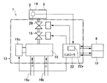
【解決手段】本発明は、吐出される湯水の温度及び流量を調整可能な水栓装置(1)であって、吐出される湯水の温度を調整するための温調操作部(10)と、吐出される湯水の流量を調整するための流調操作部(8)と、温調操作部により調整された設定温度の湯水を生成する温度調整部(16)と、流調操作部により調整された設定流量の湯水を吐出させる流量調整部(18)と、温調操作部及び流調操作部の操作に応じて、温度調整部及び流量調整部を制御する制御部(22)と、を有し、制御部は、流調操作部の操作量に対する設定流量の変化量を、設定温度に応じて変化させることを特徴としている。
【選択図】図2
Description
従って、本発明は、流調の際には吐水温度に配慮し、温調の際には吐水流量に配慮した水栓装置を提供することを目的としている。
このように構成された本発明によれば、設定温度が高い場合には、流調操作部を大きく操作しなければ設定流量を増大させることができないので、使用者の誤操作により高温大流量の吐水が為されるのを防止することができる。
このように構成された本発明によれば、設定流量が大きい場合には、温調操作部を大きく操作しなければ設定温度を上昇させることができないので、使用者の誤操作により高温大流量の吐水が為されるのを防止することができる。
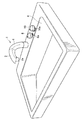
まず、図1乃至図4を参照して、本発明の第1実施形態による水栓装置を説明する。図1は、本実施形態による水栓装置全体を示す斜視図である。図2は、本実施形態による水栓装置の構成を示すブロック図である。さらに、図3及び図4は本実施形態の水栓装置の作用を示すグラフである。
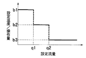
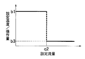
図6に示すように、本変形例の水栓装置において、コントローラ22は、単位操作量当たりの設定温度の変化量、即ち、温調操作部10を所定角度回転させたときの設定温度の変化量を、設定流量に応じて2段階に変化させるように構成されている。設定流量が0以上q2未満の場合には、単位操作量当たりの設定温度の変化量はb1にされ、設定流量がq2以上の場合には、単位操作量当たりの設定温度の変化量はb3にされる。なお、本変形例においては、設定流量q2=8[L/min]であり、単位操作量当たりの設定温度の変化量b1=0.5[゜C/deg]、b3=0.1[゜C/deg]である。
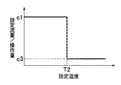
図7は、本発明の第2実施形態による水栓装置の作用を示すグラフであり、横軸に設定温度を、縦軸に単位操作量当たりの設定流量の変化量を示している。
図9は、本変形例による水栓装置の作用を示すグラフであり、横軸に設定温度を、縦軸に単位操作量当たりの設定流量の変化量を示している。
2 吐水ヘッド
2a 吐水口
4 洗面ボウル
6 水栓本体
8 流調操作部
10 温調操作部
12 水栓装置機能部
16 温調バルブ(温度調整部)
16a 給湯管
16b 給水管
18 流量調整弁(流量調整部)
20 電磁弁
22 コントローラ
22a メモリ
Claims (5)
- 吐出される湯水の温度及び流量を調整可能な水栓装置であって、
吐出される湯水の温度を調整するための温調操作部と、
吐出される湯水の流量を調整するための流調操作部と、
上記温調操作部により調整された設定温度の湯水を生成する温度調整部と、
上記流調操作部により調整された設定流量の湯水を吐出させる流量調整部と、
上記温調操作部及び上記流調操作部の操作に応じて、上記温度調整部及び上記流量調整部を制御する制御部と、を有し、
上記制御部は、上記流調操作部の操作量に対する設定流量の変化量を、設定温度に応じて変化させることを特徴とする水栓装置。 - 上記制御部は、設定温度が高い場合には、設定温度が低い場合よりも、上記流調操作部の操作量に対する設定流量の変化量を小さくする請求項1記載の水栓装置。
- 吐出される湯水の温度及び流量を調整可能な水栓装置であって、
吐出される湯水の温度を調整するための温調操作部と、
吐出される湯水の流量を調整するための流調操作部と、
上記温調操作部により調整された設定温度の湯水を生成する温度調整部と、
上記流調操作部により調整された設定流量の湯水を吐出させる流量調整部と、
上記温調操作部及び上記流調操作部の操作に応じて、上記温度調整部及び上記流量調整部を制御する制御部と、を有し、
上記制御部は、上記温調操作部の操作量に対する設定温度の変化量を、設定流量に応じて変化させることを特徴とする水栓装置。 - 上記制御部は、設定流量が大きい場合には、設定流量が小さい場合よりも、上記温調操作部の操作量に対する設定温度の変化量を小さくする請求項3記載の水栓装置。
- 上記制御部は、上記温調操作部が温度を上昇させる方向に操作された場合のみ、上記温調操作部の操作量に対する設定温度の変化量を変化させ、上記温調操作部が温度を下降させる方向に操作された場合には、上記温調操作部の操作量に対する設定温度の変化量を一定にする請求項3又は4記載の水栓装置。
Priority Applications (1)
| Application Number | Priority Date | Filing Date | Title |
|---|---|---|---|
| JP2008218520A JP5532503B2 (ja) | 2008-08-27 | 2008-08-27 | 水栓装置 |
Applications Claiming Priority (1)
| Application Number | Priority Date | Filing Date | Title |
|---|---|---|---|
| JP2008218520A JP5532503B2 (ja) | 2008-08-27 | 2008-08-27 | 水栓装置 |
Publications (2)
| Publication Number | Publication Date |
|---|---|
| JP2010053564A true JP2010053564A (ja) | 2010-03-11 |
| JP5532503B2 JP5532503B2 (ja) | 2014-06-25 |
Family
ID=42069761
Family Applications (1)
| Application Number | Title | Priority Date | Filing Date |
|---|---|---|---|
| JP2008218520A Expired - Fee Related JP5532503B2 (ja) | 2008-08-27 | 2008-08-27 | 水栓装置 |
Country Status (1)
| Country | Link |
|---|---|
| JP (1) | JP5532503B2 (ja) |
Citations (2)
| Publication number | Priority date | Publication date | Assignee | Title |
|---|---|---|---|---|
| JPH05161563A (ja) * | 1991-12-17 | 1993-06-29 | Sekisui Chem Co Ltd | シャワー装置 |
| JP2003311135A (ja) * | 2002-04-18 | 2003-11-05 | Aluvo:Kk | 流体混合装置における制御装置 |
-
2008
- 2008-08-27 JP JP2008218520A patent/JP5532503B2/ja not_active Expired - Fee Related
Patent Citations (2)
| Publication number | Priority date | Publication date | Assignee | Title |
|---|---|---|---|---|
| JPH05161563A (ja) * | 1991-12-17 | 1993-06-29 | Sekisui Chem Co Ltd | シャワー装置 |
| JP2003311135A (ja) * | 2002-04-18 | 2003-11-05 | Aluvo:Kk | 流体混合装置における制御装置 |
Also Published As
| Publication number | Publication date |
|---|---|
| JP5532503B2 (ja) | 2014-06-25 |
Similar Documents
| Publication | Publication Date | Title |
|---|---|---|
| US10753489B2 (en) | Electronic faucet device | |
| JP4385408B2 (ja) | 水栓装置 | |
| JP2004265378A (ja) | 電子制御温度調整弁 | |
| JP5532503B2 (ja) | 水栓装置 | |
| JP6982805B2 (ja) | 自動水栓装置 | |
| JP5024729B2 (ja) | 水栓装置 | |
| JP5153708B2 (ja) | 流量調節装置 | |
| JP5445337B2 (ja) | 給湯機 | |
| JP4775900B2 (ja) | 水栓装置 | |
| JP6187911B2 (ja) | 吐水装置 | |
| JP7223603B2 (ja) | 水栓及び水栓装置 | |
| JP6692525B2 (ja) | 電子水栓装置 | |
| JP5152691B2 (ja) | 水栓装置 | |
| JP3993415B2 (ja) | 自動水栓 | |
| JP5446032B2 (ja) | 湯水混合装置 | |
| JP6610934B2 (ja) | 自動水栓 | |
| JP2011033091A (ja) | 湯水混合水栓 | |
| JP2011058213A (ja) | 吐水装置 | |
| JP4775901B2 (ja) | 水栓装置 | |
| JP7527726B2 (ja) | 電子混合水栓 | |
| JP6656595B2 (ja) | 電子水栓装置 | |
| JP2010077734A (ja) | 水栓装置 | |
| JP2015155618A (ja) | シングルレバー水栓 | |
| JP2011058212A (ja) | 吐水装置 | |
| JP6607349B2 (ja) | 自動水栓 |
Legal Events
| Date | Code | Title | Description |
|---|---|---|---|
| A621 | Written request for application examination |
Free format text: JAPANESE INTERMEDIATE CODE: A621 Effective date: 20110805 |
|
| A977 | Report on retrieval |
Free format text: JAPANESE INTERMEDIATE CODE: A971007 Effective date: 20121130 |
|
| A131 | Notification of reasons for refusal |
Free format text: JAPANESE INTERMEDIATE CODE: A131 Effective date: 20121210 |
|
| A521 | Written amendment |
Free format text: JAPANESE INTERMEDIATE CODE: A523 Effective date: 20130207 |
|
| A131 | Notification of reasons for refusal |
Free format text: JAPANESE INTERMEDIATE CODE: A131 Effective date: 20130819 |
|
| A521 | Written amendment |
Free format text: JAPANESE INTERMEDIATE CODE: A523 Effective date: 20131017 |
|
| TRDD | Decision of grant or rejection written | ||
| A01 | Written decision to grant a patent or to grant a registration (utility model) |
Free format text: JAPANESE INTERMEDIATE CODE: A01 Effective date: 20140331 |
|
| R150 | Certificate of patent or registration of utility model |
Ref document number: 5532503 Country of ref document: JP Free format text: JAPANESE INTERMEDIATE CODE: R150 |
|
| A61 | First payment of annual fees (during grant procedure) |
Free format text: JAPANESE INTERMEDIATE CODE: A61 Effective date: 20140413 |
|
| LAPS | Cancellation because of no payment of annual fees |