JP2010052915A - Position recognition device and position recognition system of radio transmitter - Google Patents
Position recognition device and position recognition system of radio transmitter Download PDFInfo
- Publication number
- JP2010052915A JP2010052915A JP2008221005A JP2008221005A JP2010052915A JP 2010052915 A JP2010052915 A JP 2010052915A JP 2008221005 A JP2008221005 A JP 2008221005A JP 2008221005 A JP2008221005 A JP 2008221005A JP 2010052915 A JP2010052915 A JP 2010052915A
- Authority
- JP
- Japan
- Prior art keywords
- radio wave
- wave transmitter
- recognition
- tag
- image
- Prior art date
- Legal status (The legal status is an assumption and is not a legal conclusion. Google has not performed a legal analysis and makes no representation as to the accuracy of the status listed.)
- Granted
Links
Images


Classifications
-
- H—ELECTRICITY
- H01—ELECTRIC ELEMENTS
- H01Q—ANTENNAS, i.e. RADIO AERIALS
- H01Q1/00—Details of, or arrangements associated with, antennas
- H01Q1/12—Supports; Mounting means
- H01Q1/22—Supports; Mounting means by structural association with other equipment or articles
- H01Q1/2208—Supports; Mounting means by structural association with other equipment or articles associated with components used in interrogation type services, i.e. in systems for information exchange between an interrogator/reader and a tag/transponder, e.g. in Radio Frequency Identification [RFID] systems
- H01Q1/2216—Supports; Mounting means by structural association with other equipment or articles associated with components used in interrogation type services, i.e. in systems for information exchange between an interrogator/reader and a tag/transponder, e.g. in Radio Frequency Identification [RFID] systems used in interrogator/reader equipment
-
- H—ELECTRICITY
- H01—ELECTRIC ELEMENTS
- H01Q—ANTENNAS, i.e. RADIO AERIALS
- H01Q21/00—Antenna arrays or systems
- H01Q21/28—Combinations of substantially independent non-interacting antenna units or systems
-
- H—ELECTRICITY
- H01—ELECTRIC ELEMENTS
- H01Q—ANTENNAS, i.e. RADIO AERIALS
- H01Q3/00—Arrangements for changing or varying the orientation or the shape of the directional pattern of the waves radiated from an antenna or antenna system
- H01Q3/02—Arrangements for changing or varying the orientation or the shape of the directional pattern of the waves radiated from an antenna or antenna system using mechanical movement of antenna or antenna system as a whole
- H01Q3/04—Arrangements for changing or varying the orientation or the shape of the directional pattern of the waves radiated from an antenna or antenna system using mechanical movement of antenna or antenna system as a whole for varying one co-ordinate of the orientation
Abstract
Description
本発明は、RFIDタグの如き電波発信器の位置を認識するための位置認識装置及び位置認識システムに関する。 The present invention relates to a position recognition device and a position recognition system for recognizing the position of a radio wave transmitter such as an RFID tag.
従来、各種の物品にRFIDタグを添付し、このRFIDタグにて記憶された情報を電波にて取得することで、物品の位置等を管理するための物品管理システムが提案されている。例えば、特許文献1には、物品にRFIDタグを取り付け、このRFIDタグに対するデータの書き込みや読取りを行うRFID質問器等を用いて物品管理を行うシステムが開示されている。
2. Description of the Related Art Conventionally, there has been proposed an article management system for managing the position and the like of an article by attaching RFID tags to various articles and acquiring information stored in the RFID tag by radio waves. For example,
また、特許文献2には、アレイアンテナを用いてRFIDタグの位置を特定すると共に、アレイアンテナの周囲をカメラにて撮影し、この撮影にて得られた画像上にRFIDタグの位置を表示する装置が開示されている。
In
このようなシステムにおいては、RFIDタグからの電波を感度よく受信できるタグ読取り装置が必要となる。特に、現在国内で標準化が進められているUHF帯域の電子タグシステムでは、UHF帯の特性を活かした中距離(例えば7から10m程度)の伝送を行うことを目標としているため、タグ読取り装置にも高い出力が要求され、タグ読取り装置から送信される電波の到達範囲も広くなる。 In such a system, a tag reader capable of receiving radio waves from the RFID tag with high sensitivity is required. In particular, the UHF band RFID tag system, which is currently being standardized in Japan, aims to perform transmission over a medium distance (for example, about 7 to 10 m) utilizing the characteristics of the UHF band. Higher output is required, and the reach of radio waves transmitted from the tag reader is widened.
このような場合、特許文献1に記載のような装置では、複数のRFIDタグが近距離で配置されている場合には、これら複数のRFIDタグからの電波が混在してRFID質問器等にて受信されてしまうため、各RFIDタグの位置認識を正確に行うことが困難である。例えば、複数の収納棚が隣接配置されており、各収納棚に物品が収納されている場合において、各物品に貼付されたRFIDタグからの電波が混在してしまうため、特定の収納棚に収納された物品のみを認識することは困難である。
In such a case, in the apparatus as described in
これに対して、特許文献2に記載の装置では、アレイアンテナやカメラを用いることで、各RFIDタグの位置を一層正確に認識可能となることが予想される。しかしながら、各RFIDタグの位置を認識できたとしても、各RFIDタグに記憶されている情報(例えば当該RFIDタグや当該RFIDタグが貼付されている物品の属性情報)を各RFIDタグと関連付けることが困難であった。すなわち、各RFIDタグから属性情報を読取るためには、さらに読取り装置が必要になるが、このように読取り装置によって属性情報を読み取っても、当該属性情報が、アレイアンテナやカメラを用いて識別されたRFIDタグのいずれの情報であるのかを特定することができなかったので、RFIDタグを用いた物品管理には不十分であった。
On the other hand, in the apparatus described in
さらに、特許文献2に記載の装置では、単に認識対象領域の全体をカメラで撮影していたので、認識対象領域がある程度広い場合には、この認識対象領域をカバーするためにカメラの撮影範囲を広げる必要があり、比較的小さな物品を画像上で認識することが困難になるため、物品管理を目的とするシステムには直ちに適用することができなかった。
Furthermore, in the apparatus described in
本発明は、上記に鑑みてなされたものであって、広範な認識対象領域においても、比較的小さな物品に貼付等された電波発信器の位置と情報とを関連付けて認識することを可能とし、物品管理を目的とするシステムの実用性を高めることができる、電波発信器の位置認識装置及び位置認識システムを提供することを目的とする。 The present invention has been made in view of the above, and enables recognition of a position of a radio wave transmitter affixed to a relatively small article in association with information even in a wide recognition target area, It is an object of the present invention to provide a radio wave transmitter position recognition device and position recognition system that can enhance the practicality of a system for article management.
上述した課題を解決し、目的を達成するために、請求項1に記載の電波発信器の位置認識装置は、電波発信器が配置された認識対象領域を撮影する撮影手段と、前記電波発信器から発信された電波を受信するアレイアンテナと、前記アレイアンテナからの受信出力に基づいて、前記認識対象領域における前記アレイアンテナとの対向面上での前記電波発信器の位置を特定する受信位置特定手段と、前記受信位置特定手段にて特定された前記電波発信器の位置に基づいて、前記撮影手段にて撮影された画像上における前記電波発信器の位置を特定する画像位置特定手段と、前記電波発信器から発信された電波を受信し、当該電波に含まれる当該電波発信器の識別情報及び属性情報を取得する情報読取り手段と、前記情報読取り手段にて取得された前記電波発信器の識別情報及び属性情報の中から、前記アレイアンテナにて受信された電波に含まれる前記電波発信器の識別情報に対応する属性情報を取得することにより、前記画像位置特定手段にて位置が特定された電波発信器の属性情報を特定する属性情報特定手段とを備えることを特徴とする。
In order to solve the above-described problems and achieve the object, the radio wave transmitter position recognition apparatus according to
請求項2に記載の電波発信器の位置認識装置は、請求項1に記載の電波発信器の位置認識装置において、前記画像位置特定手段にて前記電波発信器の位置を特定した後、前記撮影手段は、前記画像位置特定手段にて特定された前記電波発信器の画像上において所定方法にて特定された位置を中心に、前記認識対象領域の拡大画像を撮影し、前記画像位置特定手段は、前記撮影手段にて撮影された拡大画像上における前記電波発信器の位置を特定することを特徴とする。
The radio wave transmitter position recognition device according to
請求項3に記載の電波発信器の位置認識装置は、請求項1又は2に記載の電波発信器の位置認識装置において、当該位置認識装置を、前記認識対象領域に沿って移動させる移動手段を備えたことを特徴とする。
The radio wave transmitter position recognition device according to
請求項4に記載の電波発信器の位置認識システムは、認識対象領域に配置された電波発信器の位置を認識するための位置認識システムであって、前記請求項1から3のいずれか一項に記載の電波発信器の位置認識装置と、前記認識対象領域において前記位置認識装置の最小認識範囲の周縁に対応する位置に設置された位置認識用の電波発信器とを備え、前記位置認識装置は、前記位置認識用の電波発信器からの電波を当該位置認識装置に設けたアレイアンテナにて受信することにより当該位置認識用の電波発信器の位置を認識し、当該認識した位置認識用の電波発信器の位置に基づいて、前記認識対象領域に対する当該位置認識装置の認識範囲を特定することを特徴とする。
The position recognition system of the radio wave transmitter according to
請求項1に記載の電波発信器の位置認識装置によれば、画像位置特定手段にて位置が特定された電波発信器の属性情報を特定することで、電波発信器の位置のみならず、電波発信器の属性情報を関連付けて認識でき、物品管理を目的とするシステムの実用性を高めることができる。
According to the position recognition device of the radio wave transmitter according to
また、請求項2に記載の電波発信器の位置認識装置によれば、電波発信器の位置を特定した後、さらに拡大画像上における電波発信器の位置を特定するので、比較的小さな物品に関しても、その位置及び属性情報を関連付けて認識でき、物品管理を目的とするシステムの実用性を一層高めることができる。
According to the radio wave transmitter position recognizing device according to
また、請求項3に記載の電波発信器の位置認識装置によれば、位置認識装置を認識対象領域に沿って移動させる移動手段を備えたので、広範な認識対象領域に配置された物品に関しても、移動手段にて位置認識装置の認識範囲を移動させた上で物品の認識を行うことができ、物品管理を目的とするシステムの実用性を一層高めることができる。 Further, according to the position recognition device for a radio wave transmitter according to the third aspect, since the moving means for moving the position recognition device along the recognition target area is provided, the article arranged in a wide recognition target area is also provided. The article can be recognized after the recognition range of the position recognition device is moved by the moving means, and the utility of the system for article management can be further enhanced.
また、請求項4に記載の電波発信器の位置認識システムによれば、位置認識用の電波発信器の位置に基づいて、認識対象領域に対する当該位置認識装置の認識範囲を特定するので、認識対象領域に対する当該位置認識装置の位置を一層正確に特定でき、物品の位置を一層高精度で認識できるので、物品管理を目的とするシステムの実用性を一層高めることができる。
According to the radio wave transmitter position recognition system according to
〔実施の形態〕
以下に添付図面を参照して、この発明に係る電波発信器の位置認識装置及び位置認識システムの一実施の形態を詳細に説明する。ただし、この実施の形態によって本発明が限定されるものではない。
Embodiment
Exemplary embodiments of a position recognition device and a position recognition system for a radio wave transmitter according to the present invention will be explained below in detail with reference to the accompanying drawings. However, the present invention is not limited by this embodiment.
(概念)
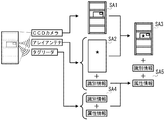
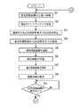
最初に、本実施の形態に係る位置認識システムによる位置認識の概念について説明する。図1は位置認識の概念を示す説明図である。この位置認識システムでは、収納棚に収納された物品の位置を認識すると共に、当該物品の属性情報を取得することを目的とする。物品は、RFIDタグによって構成された識別タグが貼付されており、この識別タグには、当該識別タグを一意に識別するための識別情報と、当該識別タグが貼付された物品の属性情報(例えば、物品の大きさ、重量、所有者)を対応付けて構成された情報が、予め記憶されている。なお、以下の各処理の説明ではステップを「S」と略記する。
(concept)
First, the concept of position recognition by the position recognition system according to the present embodiment will be described. FIG. 1 is an explanatory diagram showing the concept of position recognition. An object of this position recognition system is to recognize the position of an article stored in a storage shelf and to acquire attribute information of the article. The article is attached with an identification tag constituted by an RFID tag. This identification tag has identification information for uniquely identifying the identification tag and attribute information of the article to which the identification tag is attached (for example, , The size of the article, the weight, and the owner) are stored in advance. In the following description of each process, the step is abbreviated as “S”.
この識別タグを含む収納棚をCCDカメラにて撮影することで、収納棚の画像データを得る(SA1)。また、この識別タグから送信される電波をアレイアンテナで受信することで、識別タグの位置データと識別情報を得る(SA2)。CCDカメラにて取得した画像データに、アレイアンテナで取得した位置データを重畳することで、収納棚における識別タグの位置を示す画像データ(以下「重畳画像データ」)を得る(SA3)(識別タグの位置は星印で示す。後述する図面において同じ)。また、タグリーダによって、識別タグに記憶された識別情報と属性情報を非接触で読み取る(SA4)。そして、アレイアンテナで取得した識別情報と、タグリーダにて読み取られた識別情報とに基づいて、重畳画像データで表示された識別タグの属性情報を特定する(SA5)。これらの処理を行うことで、結果として、収納棚における識別タグの位置や、この識別タグが貼付された物品の属性情報を得ることができ、収納棚に収納された物品を遠隔的に管理することが可能となる。 The storage shelf including the identification tag is photographed with a CCD camera to obtain image data of the storage shelf (SA1). Further, by receiving the radio wave transmitted from the identification tag by the array antenna, the position data and identification information of the identification tag are obtained (SA2). Image data indicating the position of the identification tag on the storage shelf (hereinafter, “superimposed image data”) is obtained by superimposing the position data acquired by the array antenna on the image data acquired by the CCD camera (SA3) (identification tag) The position of is indicated by an asterisk (the same applies to the drawings described later). Also, the tag reader reads the identification information and attribute information stored in the identification tag in a non-contact manner (SA4). Then, based on the identification information acquired by the array antenna and the identification information read by the tag reader, the attribute information of the identification tag displayed by the superimposed image data is specified (SA5). By performing these processes, as a result, the position of the identification tag in the storage shelf and the attribute information of the article to which the identification tag is attached can be obtained, and the articles stored in the storage shelf can be managed remotely. It becomes possible.
特に、本実施の形態では、認識対象領域を複数段階(ここでは2段階)に切り替えることで、物品の位置認識を一層詳細に行うことを可能としている。以下の説明では、広域の認識範囲を「通常認識範囲」、狭域(拡大された)の認識範囲を「拡大認識範囲」と称する。概略的には、最初に、CCDカメラにて通常認識範囲を撮影し、通常認識範囲に存在する物品を特定する。次いで、この通常認識範囲に存在する物品の中で、一層詳細に認識したい物品が存在する範囲を拡大認識範囲として指示し、CCDカメラにて拡大認識範囲を撮影し、拡大認識範囲に存在する物品を特定する。 In particular, in the present embodiment, the position of the article can be recognized in more detail by switching the recognition target region to a plurality of stages (here, two stages). In the following description, the wide recognition range is referred to as “normal recognition range”, and the narrow (enlarged) recognition range is referred to as “enlarged recognition range”. In general, first, a normal recognition range is photographed by a CCD camera, and an article existing in the normal recognition range is specified. Next, among the articles existing in the normal recognition range, the range where the article to be recognized in more detail is designated as the enlarged recognition range, the enlarged recognition range is photographed by the CCD camera, and the article existing in the enlarged recognition range Is identified.
(構成)
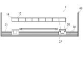
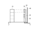
次に、本実施の形態に係る位置認識システムの構成を説明する。図2は位置認識システムの平面図、図3は図2の側面図、図4は図2の収納棚の要部斜視図である。位置認識システム1は、複数の収納棚10、これら複数の収納棚10の正面に配置された位置認識装置20、この位置認識装置20を移動させる移動機構30、及びこれら収納棚10や位置認識装置20を囲むように配置された電波吸収体40を備えて構成されている。
(Constitution)
Next, the configuration of the position recognition system according to the present embodiment will be described. 2 is a plan view of the position recognition system, FIG. 3 is a side view of FIG. 2, and FIG. 4 is a perspective view of the main part of the storage shelf of FIG. The
(構成―収納棚)
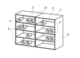
最初に、収納棚10の構成について説明する。収納棚10は、管理対象となる物品を収納する収納手段である。この収納棚10の具体的な構成な任意であるが、例えば、図4に示すように、上下一対の水平状の枠板11と左右一対の鉛直状の枠板12とを組み合わせて形成された枠体に、複数の水平状の棚板13を一定間隔を隔てて配置して構成されており、これら棚板13の上面に任意の物品2を載置することができる。ここでは、図2に示すように、このように構成された収納棚10を、鉛直状の枠板が隣接するように複数並設することによって収納列14が形成されている。
(Configuration-storage shelf)
First, the configuration of the
このように構成された収納棚10に収納される各物品2には、識別タグ3が貼付されている。この識別タグ3は、特許請求の範囲における電波発信器に対応するもので、例えば電源内蔵型(アクティブ型)のUHF帯のRFIDタグとして構成されており、内部メモリに予め記憶された情報を電波送信する。この情報としては、上述したように、識別情報(以下「タグID」)と属性情報が含まれる。
An
また、各収納棚10の正面(通路側の面)には、位置調整用タグ4が設けられている。この位置調整用タグ4は、特許請求の範囲における位置調整用の電波発信器に対応するもので、識別タグ3と同様に電源内蔵型のRFIDタグとして構成されており、内部メモリに予め記憶されたタグIDを電波送信する。ここでは、位置調整用タグ4は、後述する拡大認識範囲の外延に対応するように、各収納棚10の正面の複数個所に配置されている。なお、これら識別タグ3及び位置調整用タグ4としては、電源非内蔵型(パッシブ型)のRFIDタグを用いてもよく、この場合には、位置認識装置20に送信アンテナを設け、この送信アンテナから送信した電波によって、識別タグ3及び位置調整用タグ4に電磁誘導を生じさせて起電力を発生させてもよい。
Further, a
(構成―位置認識装置)
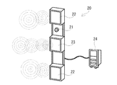
次に、位置認識装置20の構成について説明する。図5は位置認識装置20の斜視図、図6は位置認識装置20の電気的構成を示すブロック図である。位置認識装置20は、識別タグ3の位置を認識することにより、当該識別タグ3が貼付されている物品2の位置を認識するものであり、概略的には、CCDカメラ21、アレイアンテナ22、タグリーダ23、及び制御ユニット24を備える。なお、実際には、制御ユニット24を、有線又は無線にてパーソナルコンピュータの如き外部機器に接続し、制御ユニット24の機能の一部を、このパーソナルコンピュータ側で行うようにしてもよい。
(Configuration-position recognition device)
Next, the configuration of the
CCDカメラ21は、識別タグ3が配置された認識対象領域を撮影するもので、特許請求の範囲における撮影手段に対応する。ここでは、CCDカメラ21は、撮影範囲を少なくとも通常認識範囲と拡大認識範囲の2段階に切り替え可能である。この切り替えの具体的方法は任意であるが、例えば、CCDカメラ21の対物側に設けたレンズを駆動させて光学的にズームを行う方法や、CCDカメラ21にて取得された電子画像データを電子的にズームする方法を挙げることができる。なお、本実施の形態では、CCDカメラ21を用いているが、その他の任意の撮影手段、例えばCMOSカメラを採用してもよい。
The
アレイアンテナ22は、識別タグ3から送信された電波を受信する。このアレイアンテナ22は、同一特性を持つ複数の受信アンテナを、基板面上において直交する2方向に沿って並設して構成されたもので、これら各受信アンテナにて受信された電波の振幅及び位相差を後述する受信位置特定部29bによって解析することで、アレイアンテナ22に対する電波の入射方向を特定し、識別タグ3の位置を特定する。また、アレイアンテナ22は、識別タグ3から送信された電波を受信することにより、当該電波に含まれるタグIDを取得する。
The
タグリーダ23は、識別タグ3から発信された電波を受信し、当該電波に含まれる当該識別タグ3のタグID及び属性情報を取得するもので、特許請求の範囲における情報読取り手段に対応する。このタグリーダ23は、識別タグ3に対応するUHF帯のリーダであり、その具体的構成は公知のものを適用できる。
The
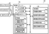
制御ユニット24は、CCDカメラ21、アレイアンテナ22、及びタグリーダ23を制御する制御手段であり、入力部25、出力部26、入出力インターフェース(以下「入出力IF」)27、記憶部28、及び制御部29を備える。
The
入力部25は、位置認識装置20に情報を入力するための入力手段であり、その具体的な構成は任意であるが、例えばタッチパネルやディプスイッチを用いて構成されている。
The
出力部26は、位置認識装置20から情報を出力するための出力手段であり、その具体的な構成は任意であるが、例えば液晶モニタやスピーカを用いて構成されている。ただし、これら入力部25や出力部26は、例えば有線又は無線ネットワークにて入出力を行うネットワークインターフェース等として構成してもよい。
The
入出力IF27は、CCDカメラ21、アレイアンテナ22、及びタグリーダ23との間における入力又は出力を行うためのインターフェースであり、その具体的な構成は任意であるが、例えば入出力接点端子やインターフェースボードを用いて構成されている。
The input / output IF 27 is an interface for performing input or output between the
記憶部28は、位置認識装置20の制御に必要な各種の情報を記憶する記憶手段であり、例えばHD(ハードディスク)やフラッシュメモリによって構成されている。特に、この記憶部28には、認識位置情報データベース(以下、データベースを「DB」と称する)28a、タグ種別情報DB28b、通常認識範囲情報DB28cが任意の方法で記憶されている。
The
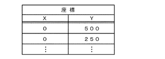
認識位置情報DB28aは、図7に構成例を示すように、複数の座標を格納して構成されている。各座標は、移動機構30における後述する水平スライダ32の座標(図示X座標)及び垂直スライダ34の座標(図示Y座標)であり、位置認識装置20を通常認識範囲の正面に移動させるための座標である。この座標は、後述する位置認識処理における認識順序に応じた順序で格納されている。
The recognized
タグ種別情報DB28bは、図8に構成例を示すように、各タグIDと、各タグIDが識別タグ3と位置調整用タグ4のいずれのタグIDであるのかを特定するための情報(図示では、該当するタグを示すフラグ)とを、相互に関連付けて構成された情報(以下「タグ種別情報」)を格納するタグ種別情報格納手段である。
As shown in the configuration example of FIG. 8, the tag
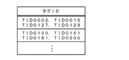
通常認識範囲情報DB28cは、図9に構成例を示すように、各通常認識範囲に対応する位置に配置された位置調整用タグ4のタグID(ここでは、各通常認識範囲の外縁位置上に存在する4つの位置調整用タグ4のタグID)を格納して構成されている。このタグIDは、後述する位置認識処理における認識順序に応じた順序で格納されている。
As shown in the configuration example of FIG. 9, the normal recognition
制御部29は、位置認識装置20の各部を制御するための制御手段であり、例えば、図示しないCPU(Central Processing Unit)及びこのCPU上で実行されるプログラム(OS及びアプリケーションプログラムを含む)によって構成されている。この制御部29は、機能概念的に、移動制御部29a、受信位置特定部29b、画像位置特定部29c、重畳表示部29d、及び属性情報特定部29eを備える。これら各部の具体的機能については後述する。これら各部は、任意の記憶媒体やネットワークを介して位置認識プログラムを当該位置認識装置20にインストールすることで構成される。
The
(構成―移動機構)
次に、図2、3に示す移動機構30の構成について説明する。移動機構30は、位置認識装置20を移動するため移動手段であり、水平レール31、水平スライダ32、垂直レール33、及び垂直スライダ34を備える。水平レール31は、水平スライダ32を摺動可能とするための水平軌道を形成する一対のレールであり、収納列14の正面に配置されており、収納列14に沿って、かつ、収納列14の長手方向の全長に至るように敷設されている。水平スライダ32は、水平レール31に載置されており、この水平スライダ32における任意の位置に水平移動する。
(Configuration-moving mechanism)
Next, the configuration of the moving
これら水平レール31及び水平スライダ32の具体的構成は任意であるが、例えば水平レール31の内部に複数の電機子を並設すると共に、水平スライダ32の内部に磁石を設け、電機子にて形成された磁場による磁石の反発力を用いて、水平スライダ32を移動させることができる(この点は、垂直レール33及び垂直スライダ34について同じ)。垂直レール33は、垂直スライダ34を摺動可能とするための垂直軌道を形成するレールであり、水平スライダ32に載置され、鉛直方向に沿った向きで、収納棚10の下端から上端に至るように敷設されている。垂直スライダ34は、垂直レール33に載置されており、この垂直スライダ34における任意の位置に垂直(鉛直)移動する。これら水平スライダ32及び垂直スライダ34は、図示しない有線又は無線にて位置認識装置20に電気的に接続されている。
The specific configurations of the
(構成―電波吸収体)
次に、図2、3に示す電波吸収体40の構成について説明する。電波吸収体40は、外部からの電波が位置認識システムに入り込むことを防止し、あるいは、識別タグ3や位置調整用タグ4から送信された電波が位置認識システムの外部に漏洩することを防止する手段である。この電波吸収体40の具体的構成は任意であるが、例えば、フェライト等の磁性体粉末を樹脂に含有させて透磁損失によって電磁波減衰を図るものや、導電性物質を絶縁体に分散させて誘導損失により電波減衰を図るものを用いた板状体を、床面上に立設することで構成される。
(Configuration-wave absorber)
Next, the configuration of the
(処理)
次に、このように構成された位置認識システムにおける位置認識処理について説明する(以下の各処理の説明ではステップを「S」と略記する)。図10、11は位置認識処理のフローチャートである。なお、以下の説明では、位置認識装置20の位置調整を自動的に行う場合について説明するが、使用者が手動で調整することも可能であり、この場合には、移動機構30の制御に関する処理の全部又は一部を省略することもできる。
(processing)
Next, a position recognition process in the position recognition system configured as described above will be described (in the following description of each process, step is abbreviated as “S”). 10 and 11 are flowcharts of the position recognition process. In the following description, a case where the position adjustment of the
使用者が位置認識装置20の入力部25を介した任意の方法で位置認識処理を起動したり、あるいは、位置認識の所定の開始タイミングが到来したことが位置認識装置20の制御部29における公知のスケジュール機能によって自動的に認識された場合に、位置認識処理が開始される。移動制御部29aは、水平スライダ32及び垂直スライダ34を駆動し、当該位置認識装置20を、所定の最初の通常認識範囲の正面に移動させる(SA1)。ここでは、図2に示す複数の収納棚10を図示左側から右側に至る順に認識対象とし、各収納棚10に関しては上段側から下段側に至る順に、2段ずつを認識対象とする。このため、SA1では、最も左側の収納棚10における上から1段目及び2段目を最初の通常認識範囲とし、この最初の通常認識範囲の正面中央に位置認識装置20を移動させる(図3の状態)。具体的には、移動制御部29aは、認識位置情報DB28aに格納されている先頭の座標を取得し、この座標に水平スライダ32及び垂直スライダ34を移動させる。
The
次いで、識別タグ3及び位置調整用タグ4から送信された電波をアレイアンテナ22を介して受信する(SA2)。そして、受信位置特定部29bは、当該受信された電波を公知の理論によって解析し、各電波の振幅及び位相差に基づいて、識別タグ3及び各位置調整用タグ4の位置を特定する(SA3)。なお、厳密には、振幅及び位相差による解析では、位置認識装置20に対する識別タグ3及び位置調整用タグ4の方向のみが特定されることになるが、ここでは、位置認識装置20に対する収納棚10の位置が予め特定されており、かつ、収納棚10における奥行き方向の距離は無視できるものと考るため、識別タグ3及び位置調整用タグ4の方向が特定されることで、位置認識装置20に対する識別タグ3及び位置調整用タグ4の位置が実質的に特定される(以下、識別タグ3及び位置調整用タグ4の位置認識において同じ)。ここで、アレイアンテナ22で受信した電波が識別タグ3と位置調整用タグ4のいずれのものであるのかは、当該アレイアンテナ22で受信された電波に含まれるタグIDを取得し、このタグIDに基づいてタグ種別情報DB28bを参照することで、区別することができる。
Next, the radio waves transmitted from the
そして、受信位置特定部29bは、SA3で位置を特定した位置調整用タグ4の中から、最初の通常認識範囲に対応する位置に配置された位置調整用タグ4を選別する(SA4)。この選別は、最初の通常認識範囲に対応する位置に配置された位置調整用タグ4のタグIDを、通常認識範囲情報DB28cから取得することで行うことができる。
Then, the reception
次いで、画像位置特定部29cは、CCDカメラ21にて、最初の通常認識範囲を撮影し(SA5)、この撮影によって得られた画像の外縁が、最初の通常認識範囲に対応する位置に配置された各位置調整用タグ4の位置に一致するように、CCDカメラ21の撮影範囲を微調整する(SA6)。このため、重畳表示部29dは、撮影によって得られた画像を出力部26のモニタ上に表示し、この画像に位置調整用タグ4の位置を重畳表示する。この重畳時の基準位置は、例えば、CCDカメラ21の中央位置とアレイアンテナ22の中央位置を予め機械的に一致させておくことで、決定することができる。そして、重畳表示において、各位置調整用タグ4の位置が画像の外縁に位置するように、CCDカメラ21の撮影範囲を調整する。撮影範囲の調整は、CCDカメラ21の撮影範囲をズームイン又はズームアウトすることで行うが、必要に応じて、CCDカメラ21の撮影方向を公知の駆動部を介して調整したり、水平スライダ32及び垂直スライダ34を駆動して当該位置認識装置20の位置を調整することで、行なってもよい(これらの調整方法は、後述するSA10の調整において同じ)。
Next, the image
このCCDカメラ21の位置の微調整後、CCDカメラ21にて最初の通常認識範囲を再び撮影し(SA7)、重畳表示部29dが、この撮影によって取得した画像データ上に、SA2で特定した識別タグ3の位置を重畳させ、この重畳画像を出力部26を介して表示出力する(SA8)。この重畳画像の出力例を図12に示す。使用者は、この表示を見て、より詳細に認識したい物品2(表示上では識別タグ3)を入力部25を介した任意の方法で指示する。図13には、図示上方右側よりの識別タグ3が指示された例を示す。このように指示された物品2を含む所定範囲(例えば、CCDカメラ21の最大拡大範囲)が、上述した拡大認識範囲となる。
After the fine adjustment of the position of the
この拡大認識範囲の指示があった場合(SA9、Yes)、画像位置特定部29cは、拡大認識範囲に配置された位置調整用タグ4の位置と、CCDカメラ21による撮影範囲の外縁とが一致するように、CCDカメラ21の撮影範囲を調整する(SA10)。
When the enlargement recognition range is instructed (SA9, Yes), the image
このCCDカメラ21の位置調整後、CCDカメラ21にて拡大認識範囲を撮影し(SA11)、重畳表示部29dが、この撮影によって取得した画像データ上に、拡大認識範囲に含まれる識別タグ3の位置を重畳させ、この重畳画像を出力部26を介して表示出力する(SA12)。この重畳画像の出力例を図14に示す。
After the position of the
また、タグリーダ23は、識別タグ3から発信された電波を受信し、当該電波に含まれる当該識別タグ3のタグID及び属性情報を取得する(SA13)。そして、属性情報特定部29eは、当該タグリーダ23にて取得された属性情報の中から、SA9で使用者に指示された拡大認識範囲に含まれる識別タグ3の属性情報を特定する(SA14)。このため、SA2で取得されたタグIDの中から、識別タグ3のタグIDを選別する。この選別は、SA2で取得されたタグIDに基づいて、タグ種別情報DB28bを参照することで行うことができる。そして、タグリーダ23にて取得された属性情報の中から、当該選別したタグIDに対応する属性情報(当該選別したタグIDと共に同一の電波に包含された状態でタグリーダ23にて受信された属性情報)を特定する。
Further, the
そして、属性情報特定部29eは、このように取得した属性情報を、所定の出力方法で出力部26を介して出力する(SA15)。この出力方法は任意であるが、例えば、属性情報をテキストデータとして出力部26を介して出力したり、SA12の重畳画像にさらに属性情報を重畳表示してもよい。図14にはこのように重畳表示した例を示す(ここでは、物品2の名称として、「保管物A」及び「保管物B」をテキスト表示している)。この重畳表示の際におけるテキストデータの出力位置の特定は、当該テキストデータ(属性情報)に対応するタグIDの重畳位置を参照して行うことができる。
Then, the attribute
次いで、移動制御部29aは、次に認識すべき通常認識範囲があるか否かを判定し(SA16)、次の通常認識範囲がある場合には(SA16、Yes)、SA1に移行して、上述した「最初の通常認識範囲」を「当該次に認識すべき通常認識範囲」に読み替えて同様の処理を行なう。以降、SA2からSA15を同様に行い、次の通常認識範囲がないと判定された場合に(SA16、No)、位置認識処理が終了する。
Next, the
(効果)
このように本実施の形態によれば、画像位置特定部29cにて位置が特定された識別タグ3の属性情報を属性情報特定部29eが特定することで、識別タグ3の位置のみならず、識別タグ3(又は識別タグ3が貼付された物品2)の属性情報を関連付けて認識でき、物品管理を目的とするシステムの実用性を高めることができる。
(effect)
Thus, according to the present embodiment, the attribute
また、本実施の形態によれば、識別タグ3の位置を特定した後、さらに拡大画像上における識別タグ3の位置を特定するので、比較的小さな物品に関しても、その位置及び属性情報を関連付けて認識でき、物品管理を目的とするシステムの実用性を一層高めることができる。
Further, according to the present embodiment, after the position of the
また、本実施の形態によれば、位置認識装置20を認識対象領域に沿って移動させる移動機構30を備えたので、広範な認識対象領域に配置された物品に関しても、移動機構30にて位置認識装置20の認識範囲を移動させた上で物品の認識を行うことができ、物品管理を目的とするシステムの実用性を一層高めることができる。
Further, according to the present embodiment, the moving
また、本実施の形態によれば、位置調整用識別タグ4の位置に基づいて、認識対象領域に対する当該位置認識装置20の認識範囲を特定するので、認識対象領域に対する当該位置認識装置20の位置を一層正確に特定でき、物品2の位置を一層高精度で認識できるので、物品管理を目的とするシステムの実用性を一層高めることができる。
Further, according to the present embodiment, since the recognition range of the
〔実施の形態に対する変形例〕
以上、本発明に係る一実施の形態について説明したが、本発明の具体的な構成及び手段は、特許請求の範囲に記載した各発明の技術的思想の範囲内において、任意に改変及び改良することができる。以下、このような変形例について説明する。
[Modifications to Embodiment]
Although one embodiment of the present invention has been described above, specific configurations and means of the present invention are arbitrarily modified and improved within the scope of the technical idea of each invention described in the claims. be able to. Hereinafter, such a modification will be described.
(解決しようとする課題や発明の効果について)
まず、発明が解決しようとする課題や発明の効果は、前記した内容に限定されるものではなく、本発明によって、前記に記載されていない課題を解決したり、前記に記載されていない効果を奏することもでき、また、記載されている課題の一部のみを解決したり、記載されている効果の一部のみを奏することがある。
(About problems to be solved and effects of the invention)
First, the problems to be solved by the invention and the effects of the invention are not limited to the above-described contents, and the present invention solves the problems not described above or has the effects not described above. There are also cases where only some of the described problems are solved or only some of the described effects are achieved.
(位置認識処理について)
図10、11に示したフローチャートは例示であり、各処理の内容やタイミングを変更することも可能である。例えば、タグリーダ23によるタグID及び属性情報の取得は、アレイアンテナ22による位置特定やCCDカメラ21による撮影の前段で行ってもよい。また、通常認識範囲に対する撮影範囲の位置合わせは、機械的手段等によって行うこともでき、この場合には、SA3〜SA6を省略してもよい。
(About position recognition processing)
The flowcharts shown in FIGS. 10 and 11 are examples, and the contents and timing of each process can be changed. For example, the
1 位置認識システム
2 物品
3 識別タグ
4 位置調整用タグ
10 収納棚
11、12 枠板
13 棚板
14 収納列
20 位置認識装置
21 CCDカメラ
22 アレイアンテナ
23 タグリーダ
24 制御ユニット
25 入力部
26 出力部
27 入出力IF
28 記憶部
28a 認識位置情報DB
28b タグ種別情報DB
28c 通常認識範囲情報DB
29 制御部
29a 移動制御部
29b 受信位置特定部
29c 画像位置特定部
29d 重畳表示部
29e 属性情報特定部
30 移動機構
31 水平レール
32 水平スライダ
33 垂直レール
34 垂直スライダ
40 電波吸収体
DESCRIPTION OF
28
28b Tag type information DB
28c Normal recognition range information DB
DESCRIPTION OF
Claims (4)
前記電波発信器から発信された電波を受信するアレイアンテナと、
前記アレイアンテナからの受信出力に基づいて、前記認識対象領域における前記アレイアンテナとの対向面上での前記電波発信器の位置を特定する受信位置特定手段と、
前記受信位置特定手段にて特定された前記電波発信器の位置に基づいて、前記撮影手段にて撮影された画像上における前記電波発信器の位置を特定する画像位置特定手段と、
前記電波発信器から発信された電波を受信し、当該電波に含まれる当該電波発信器の識別情報及び属性情報を取得する情報読取り手段と、
前記情報読取り手段にて取得された前記電波発信器の識別情報及び属性情報の中から、前記アレイアンテナにて受信された電波に含まれる前記電波発信器の識別情報に対応する属性情報を取得することにより、前記画像位置特定手段にて位置が特定された電波発信器の属性情報を特定する属性情報特定手段と、
を備えることを特徴とする電波発信器の位置認識装置。 Photographing means for photographing the recognition target area where the radio wave transmitter is disposed;
An array antenna for receiving radio waves transmitted from the radio wave transmitter;
Receiving position specifying means for specifying the position of the radio wave transmitter on the surface facing the array antenna in the recognition target area based on the reception output from the array antenna;
Based on the position of the radio wave transmitter specified by the reception position specifying means, image position specifying means for specifying the position of the radio wave transmitter on the image taken by the shooting means;
Information reading means for receiving radio waves transmitted from the radio wave transmitter and acquiring identification information and attribute information of the radio wave transmitter included in the radio waves;
The attribute information corresponding to the identification information of the radio wave transmitter included in the radio wave received by the array antenna is acquired from the identification information and attribute information of the radio wave transmitter acquired by the information reading means. Attribute information specifying means for specifying the attribute information of the radio wave transmitter whose position is specified by the image position specifying means,
A position recognizing device for a radio wave transmitter, comprising:
前記撮影手段は、前記画像位置特定手段にて特定された前記電波発信器の画像上において所定方法にて特定された位置を中心に、前記認識対象領域の拡大画像を撮影し、
前記画像位置特定手段は、前記撮影手段にて撮影された拡大画像上における前記電波発信器の位置を特定すること、
を特徴とする請求項1に記載の電波発信器の位置認識装置。 After specifying the position of the radio wave transmitter by the image position specifying means,
The imaging means captures an enlarged image of the recognition target area around a position specified by a predetermined method on the image of the radio wave transmitter specified by the image position specifying means,
The image position specifying means specifies a position of the radio wave transmitter on an enlarged image photographed by the photographing means;
The position recognition apparatus for a radio wave transmitter according to claim 1.
を備えたことを特徴とする請求項1又は2に記載の電波発信器の位置認識装置。 Moving means for moving the position recognition device along the recognition target area;
The position recognition device for a radio wave transmitter according to claim 1 or 2, further comprising:
前記請求項1から3のいずれか一項に記載の電波発信器の位置認識装置と、
前記認識対象領域において前記位置認識装置の最小認識範囲の周縁に対応する位置に設置された位置認識用の電波発信器とを備え、
前記位置認識装置は、前記位置認識用の電波発信器からの電波を当該位置認識装置に設けたアレイアンテナにて受信することにより当該位置認識用の電波発信器の位置を認識し、当該認識した位置認識用の電波発信器の位置に基づいて、前記認識対象領域に対する当該位置認識装置の認識範囲を特定すること、
を特徴とする電波発信器の位置認識システム。 A position recognition system for recognizing the position of a radio wave transmitter arranged in a recognition target area,
A position recognition device for a radio wave transmitter according to any one of claims 1 to 3,
A radio wave transmitter for position recognition installed at a position corresponding to the periphery of the minimum recognition range of the position recognition device in the recognition target area,
The position recognizing device recognizes the position of the position recognizing radio wave transmitter by receiving the radio wave from the position recognizing radio wave transmitter by an array antenna provided in the position recognizing device, and recognizes the position. Identifying the recognition range of the position recognition device for the recognition target area based on the position of the position recognition radio wave transmitter;
A position recognition system for radio wave transmitters.
Priority Applications (1)
| Application Number | Priority Date | Filing Date | Title |
|---|---|---|---|
| JP2008221005A JP5236398B2 (en) | 2008-08-29 | 2008-08-29 | Radio wave transmitter position recognition device and position recognition system |
Applications Claiming Priority (1)
| Application Number | Priority Date | Filing Date | Title |
|---|---|---|---|
| JP2008221005A JP5236398B2 (en) | 2008-08-29 | 2008-08-29 | Radio wave transmitter position recognition device and position recognition system |
Publications (2)
| Publication Number | Publication Date |
|---|---|
| JP2010052915A true JP2010052915A (en) | 2010-03-11 |
| JP5236398B2 JP5236398B2 (en) | 2013-07-17 |
Family
ID=42069241
Family Applications (1)
| Application Number | Title | Priority Date | Filing Date |
|---|---|---|---|
| JP2008221005A Active JP5236398B2 (en) | 2008-08-29 | 2008-08-29 | Radio wave transmitter position recognition device and position recognition system |
Country Status (1)
| Country | Link |
|---|---|
| JP (1) | JP5236398B2 (en) |
Cited By (7)
| Publication number | Priority date | Publication date | Assignee | Title |
|---|---|---|---|---|
| WO2014136559A1 (en) * | 2013-03-04 | 2014-09-12 | 日本電気株式会社 | Article management system, information processing device, and control method and control program therefor |
| EP3276742A1 (en) * | 2016-07-26 | 2018-01-31 | Toshiba TEC Kabushiki Kaisha | Tag reading device |
| KR20190114008A (en) * | 2017-03-02 | 2019-10-08 | 마이크론 테크놀로지, 인크. | Method and apparatus for determining real time location information of RFID device |
| JP2021042080A (en) * | 2016-07-28 | 2021-03-18 | ボストン ダイナミクス,インコーポレイテッド | Inventory control |
| US10958593B2 (en) | 2017-03-02 | 2021-03-23 | Micron Technology, Inc. | Methods and apparatuses for processing multiple communications signals with a single integrated circuit chip |
| JP2021071296A (en) * | 2019-10-29 | 2021-05-06 | 三菱電機ビルテクノサービス株式会社 | Wireless tag position detection system |
| JP7345367B2 (en) | 2019-11-25 | 2023-09-15 | 東芝テック株式会社 | Information processing device, information processing system, and program |
Citations (4)
| Publication number | Priority date | Publication date | Assignee | Title |
|---|---|---|---|---|
| JP2004175509A (en) * | 2002-11-27 | 2004-06-24 | Nec Corp | Article location management device |
| JP2004342007A (en) * | 2003-05-19 | 2004-12-02 | Nippon Telegr & Teleph Corp <Ntt> | Article retrieval system |
| JP2007200035A (en) * | 2006-01-26 | 2007-08-09 | Ntt Docomo Inc | Wireless tag reading system and method |
| JP2007297181A (en) * | 2006-04-28 | 2007-11-15 | Nec Corp | Rfid tag recognition system, rfid tag recognizing method, and program for performing rfid tag recognizing method |
-
2008
- 2008-08-29 JP JP2008221005A patent/JP5236398B2/en active Active
Patent Citations (4)
| Publication number | Priority date | Publication date | Assignee | Title |
|---|---|---|---|---|
| JP2004175509A (en) * | 2002-11-27 | 2004-06-24 | Nec Corp | Article location management device |
| JP2004342007A (en) * | 2003-05-19 | 2004-12-02 | Nippon Telegr & Teleph Corp <Ntt> | Article retrieval system |
| JP2007200035A (en) * | 2006-01-26 | 2007-08-09 | Ntt Docomo Inc | Wireless tag reading system and method |
| JP2007297181A (en) * | 2006-04-28 | 2007-11-15 | Nec Corp | Rfid tag recognition system, rfid tag recognizing method, and program for performing rfid tag recognizing method |
Cited By (17)
| Publication number | Priority date | Publication date | Assignee | Title |
|---|---|---|---|---|
| US11527054B2 (en) | 2013-03-04 | 2022-12-13 | Nec Corporation | Article management system, information processing apparatus, and control method and control program of information processing apparatus |
| US10438084B2 (en) | 2013-03-04 | 2019-10-08 | Nec Corporation | Article management system, information processing apparatus, and control method and control program of information processing apparatus |
| WO2014136559A1 (en) * | 2013-03-04 | 2014-09-12 | 日本電気株式会社 | Article management system, information processing device, and control method and control program therefor |
| US10885374B2 (en) | 2013-03-04 | 2021-01-05 | Nec Coporation | Article management system, information processing apparatus, and control method and control program of information processing apparatus |
| EP3276742A1 (en) * | 2016-07-26 | 2018-01-31 | Toshiba TEC Kabushiki Kaisha | Tag reading device |
| JP7118123B2 (en) | 2016-07-28 | 2022-08-15 | ボストン ダイナミクス,インコーポレイテッド | Inventory control |
| JP2021042080A (en) * | 2016-07-28 | 2021-03-18 | ボストン ダイナミクス,インコーポレイテッド | Inventory control |
| CN110383910A (en) * | 2017-03-02 | 2019-10-25 | 美光科技公司 | For determining the method and apparatus of the real-time position information of RFID device |
| KR102252835B1 (en) * | 2017-03-02 | 2021-05-20 | 마이크론 테크놀로지, 인크. | Method and apparatus for determining real-time location information of RFID device |
| US11055657B2 (en) | 2017-03-02 | 2021-07-06 | Micron Technology, Inc. | Methods and apparatuses for determining real-time location information of RFID devices |
| US10958593B2 (en) | 2017-03-02 | 2021-03-23 | Micron Technology, Inc. | Methods and apparatuses for processing multiple communications signals with a single integrated circuit chip |
| KR20190114008A (en) * | 2017-03-02 | 2019-10-08 | 마이크론 테크놀로지, 인크. | Method and apparatus for determining real time location information of RFID device |
| US11677685B2 (en) | 2017-03-02 | 2023-06-13 | Micron Technology, Inc. | Methods and apparatuses for processing multiple communications signals with a single integrated circuit chip |
| US11783287B2 (en) | 2017-03-02 | 2023-10-10 | Micron Technology, Inc. | Methods and apparatuses for determining real-time location information of RFID devices |
| JP2021071296A (en) * | 2019-10-29 | 2021-05-06 | 三菱電機ビルテクノサービス株式会社 | Wireless tag position detection system |
| JP7325297B2 (en) | 2019-10-29 | 2023-08-14 | 三菱電機ビルソリューションズ株式会社 | Wireless tag position detection system |
| JP7345367B2 (en) | 2019-11-25 | 2023-09-15 | 東芝テック株式会社 | Information processing device, information processing system, and program |
Also Published As
| Publication number | Publication date |
|---|---|
| JP5236398B2 (en) | 2013-07-17 |
Similar Documents
| Publication | Publication Date | Title |
|---|---|---|
| JP5236398B2 (en) | Radio wave transmitter position recognition device and position recognition system | |
| US10091429B2 (en) | Mobile terminal having two cameras and method for storing images taken by two cameras | |
| US10373389B2 (en) | Mobile terminal and method of operating thereof | |
| US10499782B2 (en) | Robot cleaner and a system including the same | |
| CN107959788B (en) | Mobile terminal and operating method thereof | |
| US10175736B2 (en) | Touch panel and a wireless input apparatus and mobile terminal including touch panel | |
| KR20170123125A (en) | Mobile terminal and method for controlling the same | |
| US9454301B2 (en) | Mobile terminal controlled by at least one touch and method of controlling therefor | |
| CN107948394A (en) | Mobile terminal | |
| KR20170139408A (en) | Moving picture photographing apparatus having dual cameras | |
| KR20170013555A (en) | Mobile terminal and method for controlling the same | |
| KR20170079198A (en) | Mobile terminal and operating method thereof | |
| KR20180037923A (en) | Mobile terminal and control method thereof | |
| KR20180038445A (en) | Mobile terminal | |
| CN107908990B (en) | Radio frequency card positioning scanning system | |
| KR101830739B1 (en) | Touch panel, mobile terminal and wireless input apparatus | |
| KR20170041098A (en) | Mobile device and method for operating the same | |
| JP2006040059A (en) | Object information acquiring device, object authentication devices, and control method thereof | |
| CN109154711A (en) | Camera model and and its auto-focusing method | |
| JP2018101198A (en) | Radio communication device and ticket examination machine | |
| KR20170024276A (en) | Mobile terminal and method for controlling the same | |
| KR20160080538A (en) | Mobile terminal and method for controlling the same | |
| KR20160148926A (en) | Mobile terminal and method for controlling the same | |
| KR102637419B1 (en) | Mobile terminal and 3D image conversion method thereof | |
| KR20180049629A (en) | Touch input apparatus using a stylus pen and method for detecting touch thereof |
Legal Events
| Date | Code | Title | Description |
|---|---|---|---|
| A621 | Written request for application examination |
Free format text: JAPANESE INTERMEDIATE CODE: A621 Effective date: 20110624 |
|
| A977 | Report on retrieval |
Free format text: JAPANESE INTERMEDIATE CODE: A971007 Effective date: 20130311 |
|
| TRDD | Decision of grant or rejection written | ||
| A01 | Written decision to grant a patent or to grant a registration (utility model) |
Free format text: JAPANESE INTERMEDIATE CODE: A01 Effective date: 20130313 |
|
| A61 | First payment of annual fees (during grant procedure) |
Free format text: JAPANESE INTERMEDIATE CODE: A61 Effective date: 20130327 |
|
| R150 | Certificate of patent or registration of utility model |
Free format text: JAPANESE INTERMEDIATE CODE: R150 Ref document number: 5236398 Country of ref document: JP Free format text: JAPANESE INTERMEDIATE CODE: R150 |
|
| FPAY | Renewal fee payment (event date is renewal date of database) |
Free format text: PAYMENT UNTIL: 20160405 Year of fee payment: 3 |