JP2010052773A - Synthetic resin plug cap excellent in segregation disposal performance - Google Patents
Synthetic resin plug cap excellent in segregation disposal performance Download PDFInfo
- Publication number
- JP2010052773A JP2010052773A JP2008220202A JP2008220202A JP2010052773A JP 2010052773 A JP2010052773 A JP 2010052773A JP 2008220202 A JP2008220202 A JP 2008220202A JP 2008220202 A JP2008220202 A JP 2008220202A JP 2010052773 A JP2010052773 A JP 2010052773A
- Authority
- JP
- Japan
- Prior art keywords
- region
- wall portion
- wall
- weakening line
- axial
- Prior art date
- Legal status (The legal status is an assumption and is not a legal conclusion. Google has not performed a legal analysis and makes no representation as to the accuracy of the status listed.)
- Granted
Links
Images


Abstract
Description
本発明は、合成樹脂製打栓キャップ、より詳細には、使用後に、キャップ本体を容器口部から容易に取り外して廃棄することが可能な分別廃棄性を有すると共にタンパーエビデント特性(不正にキャップを容器口部から取り除こうとすると、その痕跡が残留する特性)を備えた合成樹脂製打栓キャップに関する。 The present invention relates to a synthetic resin stopper cap. More specifically, the present invention has a separable disposal property that allows the cap body to be easily removed from the container mouth portion and disposed of after use, and has a tamper-evident characteristic (tampered cap) When the material is removed from the container mouth portion, the present invention relates to a synthetic resin stopper cap having a characteristic that a trace remains.
容器口部に打栓により嵌合固定されるキャップ本体と該キャップ本体に開閉自在に設けられた上蓋とからなる合成樹脂製打栓キャップ(以下、単に打栓キャップという。)は、使用後工具等を用いない限り容器口部から容易に取外すことができない構造になっている。しかしながら、最近では、資源の再利用などの観点から、容器とキャップの分別廃棄性が要求され、内容物取り出し後の使用済み容器から、格別の工具を用いることなく、キャップ本体を容易に取り外すことができるようにした分別廃棄性に優れた打栓キャップが種々提案されている(例えば、特許文献1)。 A synthetic resin stopper cap (hereinafter simply referred to as a stopper cap) comprising a cap main body fitted and fixed to the container mouth portion by a stopper and an upper lid that can be freely opened and closed on the cap body is a tool after use. Unless it uses etc., it has a structure that cannot be easily removed from the container mouth. However, recently, from the viewpoint of reusing resources, the container and cap must be separated and disposed of, and the cap body can be easily removed from the used container after the contents have been removed without using a special tool. Various types of stopper caps that are excellent in separation and disposal have been proposed (for example, Patent Document 1).
本出願人は、上記特許文献1に記載されているものをさらに改良してより分別廃棄性に優れた打栓キャップとして、図7、8に示すものを提供した(特許文献2参照)。該提案の打栓キャップは、容器口部が嵌合固定されるキャップ本体61とキャップ本体61に開閉自在にヒンジ結合された上蓋62からなり、キャップ本体61の筒状側壁66(図8参照)には、内側壁部66aと外側壁部66bに周方向スリット68が形成されている外側壁部を引き裂き可能な引き裂き領域Xと、引き裂き不能な固定領域Yが形成されている。そして、図7に示す筒状側壁66のA〜E、Pの各位置での断面を図8に拡大して示すように、引き裂き領域Xと固定領域Yの一方の境界部には、外側壁部66bに上端から下端まで軸方向スコア67が形成され(図8A)、引き裂き領域Xでは、筒状側壁の厚み部分を上端から下方に深く延びるスリット68により、内側壁部の下端部分が引き裂き可能な薄肉の連結部69で外側壁部に連結されており(図8A〜D、P)、固定領域Xでは、内側壁部66aと外側壁部66bとが肉厚連結部71で一体化され(E)、引き裂き領域Xにおける内側壁部66aでは、容器口部との係合突起70が形成されていない係合突起の寸断部分73が薄肉に形成されている(図8P)。
The present applicant has further improved the one described in
上記提案の打栓キャップ60は上記構成により、内容液を取り出した後の使用済みキャップについて、キャップ本体61を容器口部から取り外すには、上蓋61を開いて横方向又は下方に引っ張ると、まず軸方向スコア67が破断されて、周方向の引き裂き口が形成され、ついで上蓋62を水平方向横倒しの状態で周方向に引っ張ることにより、内側壁部66aと外側壁部66bと連結する薄肉の連結部69が破断されて、引き裂き領域Xで外側壁部が内側壁部から引き剥がされ、それにより内側壁部の内周面に形成されている複数(図7では8箇所)の寸断部分73で分離されている複数の係合突起70と容器との係合が緩くなり、キャップ本体61を容器口部から簡単に引き剥がすことが可能となる。
The proposed
しかしながら、上記従来の合成樹脂製打栓キャップは、未開封のまま上蓋62を垂直状態に開いて故意に垂直に引っ張り上げた場合、軸方向スコア67に引き裂き力が効果的に作用せずに、軸方向スコア67が破断せずに引っ張り力が外側壁部全体に引き上げ荷重として作用してしまい、その状態で強く上方に引き上げると図9に示すようにキャップ本体61が容器口部72からスポッと抜けてしまう場合がある。このようにして抜けたキャップを上蓋を閉じた状態で容器口部に強く押し込むと軸方向スコアが破断されていない元の未開封状態になって、一度開封されたことが分からない状態に復帰してしまい、タンパーエビデント性に欠けるという問題点がある。
However, when the above-mentioned conventional synthetic resin stopper cap is unopened and the
そこで本発明は、流通段階でいたずら等により軸方向スコアが破断しない状態で打栓キャップが容器から外れてしまうことを確実に防止することができ、タンパーエビデント性に優れ、且つ使用後には工具等を使用しないで容器から簡単に除去できる合成樹脂製打栓キャップを提供することを目的とする。 Therefore, the present invention can surely prevent the stopper cap from being detached from the container in a state where the axial score does not break due to mischief or the like in the distribution stage, has excellent tamper evidence, and has a tool after use. It is an object of the present invention to provide a synthetic resin stopper cap that can be easily removed from a container without using any other material.
本発明者は、上記課題を解決するために種々研究した結果、上蓋を上方に引っ張ったときにキャップのすっぽ抜けが生じる原因は、従来のキャップの場合、ヒンジ連結部の下方位置では外側壁部と内側壁部の連結部は完全に切れているか弱化部となっているが、軸方向スコアからヒンジ連結部と反対側の部分は、外側壁部と内側壁部の下端が連結しているため、引き上げ力は軸方向弱化線に対して垂直方向に作用し、軸方向弱化線を引裂く力としては殆ど作用せずに、引張り力が軸方向弱化線部からその外側まで達してしまうことに原因があることが判明し、さらに研究した結果本発明に通達したものである。 As a result of various studies conducted by the present inventor to solve the above-mentioned problems, the cause of the cap slipping out when the upper lid is pulled upward is that in the case of the conventional cap, the outer wall is located below the hinge connecting portion. The connection part between the inner wall part and the inner wall part is completely cut or weakened, but the outer wall part and the lower end of the inner wall part are connected to the part opposite to the hinge connection part from the axial score. Therefore, the pulling force acts in a direction perpendicular to the axial direction weakening line, hardly acts as a force to tear the axial direction weakening line, and the tensile force reaches from the axial direction weakening line portion to the outside thereof. As a result of further research, the present invention has been notified.
上記課題を解決する本発明の合成樹脂製打栓キャップは、容器口部に打栓により嵌合固定されるキャップ本体と、該キャップ本体に開閉自在にヒンジ結合された上蓋とからなり、前記キャップ本体は、頂板部とその周縁部から垂下している筒状側壁を有し、該筒状側壁は上端から下方に延びている周方向スリットにより内側壁部と外側壁部に区画され、該外側壁部の上端部にヒンジ連結部により前記上蓋がヒンジ結合され、前記内側壁部の下端内面には容器口部の外面と係合する厚肉の係合突起が形成されてなり、前記外側壁部を前記内側壁部から連結領域を残して周方向に引き裂き可能に形成されてなる合成樹脂製打栓キャップにおいて、前記外側壁部には前記ヒンジ連結部近傍に軸方向弱化線が形成され、且つ前記外側壁部と前記内側壁部との下端間には、分離領域、易破断領域及び連結領域が周方向に順に形成され、前記分離領域は前記軸方向弱化線を基準として、前記ヒンジ連結部と反対側に5〜60゜だけ離れた位置から開始されて、ヒンジ連結部側に前記軸方向弱化線から25〜165゜離れた位置まで延びる領域に形成されていることを特徴とするものである。なお、前記「周方向スリット」は、必ずしも全周に亘るスリットのみを意味するのではなく、連結部領域にはスリットを形成しない場合も含むものである。
The synthetic resin stopper cap of the present invention that solves the above problems comprises a cap body that is fitted and fixed to a container mouth portion by stoppering, and an upper lid that is hinged to the cap body so as to be openable and closable. The main body has a top plate part and a cylindrical side wall depending from the peripheral part, and the cylindrical side wall is partitioned into an inner side wall part and an outer side wall part by a circumferential slit extending downward from the upper end. The upper lid is hinged to the upper end portion of the wall portion by a hinge connecting portion, and a thick engagement protrusion that engages with the outer surface of the container mouth portion is formed on the lower end inner surface of the inner wall portion, and the outer wall In the synthetic resin stopper cap formed so that the portion can be torn in the circumferential direction leaving the connecting region from the inner wall portion, an axial weakening line is formed in the vicinity of the hinge connecting portion on the outer wall portion, And the outer wall and the inner wall A separation region, an easily breakable region, and a connection region are sequentially formed in the circumferential direction between the lower ends of the first and second portions, and the separation region is 5 to 60 degrees on the opposite side of the hinge connection portion with respect to the axial weakening line. It is characterized in that it is formed in a region starting from a distant position and extending to a
前記分離領域は、前記連結領域に隣接する連結領域側分離領域、前記ヒンジ連結部下方に位置するヒンジ連結部下方分離領域、及び前記易破断領域に隣接する易破断領域側分離領域が周方向に順次連続してなり、前記分離領域の周方向長さは前記筒状側壁の周方向全周の50%以下であり、前記易破断領域側分離領域は前記軸方向弱化線と反対側に位置するヒンジ連結部端部下方位置から該ヒンジ連結部と反対側に5〜110゜だけ離れた位置まで延びる領域に形成されていることが望ましい。 The separation region includes a connection region side separation region adjacent to the connection region, a hinge connection portion lower separation region located below the hinge connection portion, and an easily breakable region side separation region adjacent to the easy break region in the circumferential direction. The separation region is continuously continuous, the circumferential length of the separation region is 50% or less of the entire circumferential circumference of the cylindrical side wall, and the easy break region separation region is located on the opposite side of the axial weakening line. It is desirable to form in a region extending from a position below the end of the hinge connecting portion to a position away from the hinge connecting portion by 5 to 110 °.
本願の請求項1〜2に記載の発明の合成樹脂製打栓キャップによれば、容器に装着してある打栓キャップの上蓋を開いて引き上げたとき、ヒンジ連結部下方の外側壁部が持ち上がると共に、軸方向弱化線を基準としてヒンジ連結部下方部と反対側に形成されている分離領域も同時に引き上げられるので、前記分離領域開始点を起点として分離領域が斜めに持ち上がり、その結果、前記軸方向弱化線部も斜めに持ち上がり、前記軸方向弱化線にはその上端から該弱化線部を引裂く分力が作用し、確実に軸方向弱化線が破断する。したがって、本発明によれば軸方向弱化線を破断することなく、キャップ本体を容器口から工具を用いずに除去することは不可能であり、タンパーエビデント性に優れている。
According to the synthetic resin stopper cap of the invention described in
また、請求項2に記載の発明によれば、より確実に前記軸方向弱化線を破断することができ、且つ前記分離領域がキャップ本体の容器口部への保持力に影響を与えることなく、キャップ本体の容器口部への強い保持力を維持できる。
Further, according to the invention of
以下図面に基づいて、本実施形態に係る合成樹脂製打栓キャップを詳細に説明する。
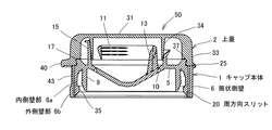
図1は本実施形態に係る合成樹脂製打栓キャップの正面断面図を示し、図2はその上蓋を開いた状態での平面図、図3はその底面図である。
本実施形態の合成樹脂製打栓キャップ50は、キャップ本体1と上蓋2とから成り、キャップ本体1は、頂板部5と、その周縁部から垂下している筒状側壁6とから構成されている。頂板部5の内面には、筒状側壁6とは間隔を置いて下方に延びているインナーリング9が形成されている。このインナーリング9と筒状側壁6との間の空間に図5に示すように容器口部45が嵌め込まれることにより、キャップ本体1は、容器口部45に装着されて容器が密封される。
Hereinafter, a synthetic resin stopper cap according to the present embodiment will be described in detail with reference to the drawings.
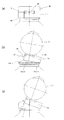
FIG. 1 is a front sectional view of a synthetic resin stopper cap according to the present embodiment, FIG. 2 is a plan view with its upper lid opened, and FIG. 3 is a bottom view thereof.
The synthetic
また、頂板部5には、注出用開口を形成するためのスコア10が形成されており、頂板部5の上面側には、スコア破断用のプルリング11が支柱13を介して設けられている。さらに、頂板部5の上面側には、スコア10を取り囲むようにして、注出液案内用の筒状突起15が形成されており、注出用開口を介して注ぎ出された内容液は、この筒状突起15によって案内される。この筒状突起15の上端は、ラッパ状に広がって液の排出をスムーズに行い得るようになっており、後述するヒンジ連結部25側において、筒状突起15の背が低く形成され、上蓋2を閉じるときに上蓋2の旋回を妨害しないように構成されている。また、筒状突起15の外側には、上蓋2を保持するための周状突起17が形成されている。
The
また、キャップ本体1の筒状側壁6は、内側壁部6aと外側壁部6bとから形成されており、筒状側壁6の厚み部分について、その全周にわたって上端から下方に延びるスリット20により、内側壁部6aと外側壁部6bとに区画されている。尚、スリット20は、必ずしも全周にわたって形成されることはなく、円弧状に形成されていてもよい。
Further, the cylindrical side wall 6 of the
上蓋2は、天板部31と、天板部31の周縁から延びているスカート部33とから形成され、図1に明示してあるように、キャップ本体1の筒状側壁6の外側壁部6bの上端部分にヒンジ連結部25によってスカート部33の下端部が連結されている。このヒンジ連結部25は、中央の幅広バンド部25aと、その両側の小幅バンド部25b、25cから形成されている(図2)。
The
天板部31の内面には、シール用の周状突起34が形成されている。上蓋2を閉じたとき、シール用の周状突起34が注出液案内用の筒状突起15の内面に密着し、スコア10を破断して注出用開口形成後のシール性が確保される。また、上蓋2のスカート部33の内面下方部分には、凹部37が形成されており、キャップ本体1の周状突起17の上端部が、この凹部37と係合することにより、閉じられた上蓋2が安定に保持されるようになっている。
A
さらに、上蓋2のスカート部33の外面には、前述したヒンジ連結部25とは反対側部分に、開封用鍔40が設けられている。この開封用鍔40を指で引っ掛けて上蓋2を上方に持ち上げることにより上蓋2の開封を容易に行うことができる。また、キャップ本体1の筒状側壁6(外側壁部6b)の外面には、上蓋2を閉じたときに上記の開封用鍔40が位置する部分に、滑らかな凹面43が形成されており、開封用鍔40の指での引っ掛けを容易に行うことができるようになっている。
Further, an opening
以上の構造は、上記特許文献1に記載されたものと同様な構造であるが、本実施形態に係る打栓キャップ50は、特に筒状壁部6の外側壁部6bと内側壁部6aとの間に形成される周方向スリット20の下端の形態及び外側壁部6bに形成される軸方向弱化線27及びヒンジ連結部25の位置を以下に詳述するように工夫することによって上記問題点を解決したものである。
The above structure is the same structure as that described in
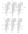
即ち、本実施形態の打栓キャップでは、筒状側壁6を内側壁部6aと外側壁部6bに区画する周方向スリット20の下方位置の形態は、図4に周方向の要部位置での断面を拡大して示すように、スリット20が完全に下端まで貫通して内側壁部6aと外側壁部6b下端が繋がってなく分離している部分(以下、この部分を分離領域21aという)と、外側壁部6bを周方向に引っ張ることによって容易に破断できる易破断連結部23(図4(d)(e))で繋がっている易破断領域部分(以下、この部分を易破断領域21bという)と、内側壁部6aと外側壁部6bとが容易に破断することができない所定の肉厚の非破断連結部24(図4(f))で完全に繋がっている部分(以下、この部分を連結領域21cという)があり、その3つの形態の組み合わせからなり、その組み合わせ範囲に特徴を有する。なお、分離領域21aの形態は、スリットが完全に下端位置まで貫通しているものに限らず、下端が薄膜状に繋がっていているもの等、微弱の力で直ぐに破断でき実質上分離しているものと同様に機能するものであればよい。さらに、連結領域21cの形態は、肉厚の非破断連結部24をスリットを全く設けないことにより形成することもできる。
That is, in the stopper cap of the present embodiment, the form of the lower position of the circumferential slit 20 that divides the cylindrical side wall 6 into the
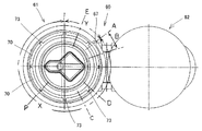
図3に筒状側壁6における分離領域21a、易破断領域21b、連結領域21cが形成される区間配置の概念を示し、それぞれの領域における図3に示す主要位置での断面形状を図4に拡大して示している。
FIG. 3 shows the concept of the section arrangement in which the
本実施形態では、外側壁部6bには、上記ヒンジ連結部25の一方側の端部(一方の小幅のバンド部25b)の近傍において、その上端から下端乃至その近傍まで延びている軸方向弱化線27が形成されており、該軸方向弱化線27は、キャップ使用後に容器からキャップを除去するに際して、上蓋を開いた状態で下方に引っ張ることによって外側壁部を該弱化線から軸方向に破断させる役割を果たすものである。本実施形態では、軸方向弱化線27は、外側壁部の外周面側に薄肉部29を残した軸方向スコアとして形成されているが、必ずしもそれに限らずミシン目など外側壁部6bを軸方向に容易に引裂き可能であればよい。
In the present embodiment, the
そして、図4(a)に拡大して示すように軸方向弱化線27の上端から所定深さに切り込み(ノッチ)28が形成され、上蓋を下方に引き下げた場合、軸方向弱化線27が引き裂き易いように構成されていると共に、不正にキャップを取り除こうとして上蓋を上方に引き上げた場合、該切り込みから破断が開始されて、軸方向スコアが容易に且つ確実に破断できるように構成されている。軸方向弱化線27は、前記切り込み28が形成されている部分以外は、前記したように薄肉部29を残してスコアが形成され、それにより引き裂き前まで外側壁部が破断されずに一体に繋がっており、形状を保持している。
Then, as shown in an enlarged view in FIG. 4A, a
本実施形態では、軸方向弱化線27は1個のみ形成され外側壁部6bは1ヶ所のみで軸方向に切断されるが、前記切り込み28は、他方の小幅のバンド部25c近傍にも設けてもよい。他方の小幅バンド部近傍にも切り込みを設けることによって、キャップを容器から除去するときに、外側壁部を軸方向に破断し、次いで周方向に引っ張って易破断領域21bを破断する際、上蓋2が水平方向に倒れ易く周方向破断がより容易となる。
In the present embodiment, only one
そして、本実施形態では、軸方向弱化線27を基準にして周方向左右に前記分離領域21aが形成されている。本実施形態における分離領域21aは、軸方向弱化線27を基準として、前記ヒンジ連結部25と反対側(図3における回転方向左側)に5〜60゜、望ましくは15〜35゜だけ離れた位置から開始されて、前記ヒンジ連結部側に前記軸方向弱化線27から25〜165゜、望ましくは165〜110゜離れた位置まで延びる領域に形成されている。分離領域が軸方向弱化線27からヒンジ連結部25と反対側周方向に5゜以下であるとその作用が生じ難く、60゜以上であると分離領域が広くなり、キャップ本体の容器口部への係合が緩くなると共に、使用状態でヒンジ連結部が位置する部分が緩くなり、上蓋の開閉が不安定になり好ましくない。また、分離領域が軸方向弱化線27からヒンジ連結部側に25゜以下であるとその作用が生じ難く、165゜以上であると上蓋の開閉が不安定になると共に軸方向弱化線27の破断が起こり難くなるおそれがある。
And in this embodiment, the said isolation | separation area |
更に好ましい本実施形態における分離領域21aは、前記連結領域21cに隣接する軸方向弱化線27までの連結領域側分離領域21a−1、前記ヒンジ連結部下方に位置するヒンジ連結部下方分離領域21a−2、及び前記易破断領域21bに隣接する易破断領域側分離領域21a−3が周方向に順次連続して形成されている。そして、前記連結領域側分離領域21a−1に続いて前記軸方向弱化線27からヒンジ連結部の下方位置(この部分の分離領域をヒンジ連結部下方分離領域21a−2とする)を通過して小幅バンド部25cの下方位置から図3において右回転周方向に5〜110゜、望ましくは25〜45゜の範囲まで易破断領域側分離領域21a−3が形成されている。易破断領域側分離領域21a−3が5゜以下であると分離領域の外側壁部6bが上方に上がり難くなり、軸方向弱化線が破断され難くなる。しかしながら、110゜以上に設けると装着状態での内側壁部の拘束が弱くなるので、上記範囲内とする。
Further, in the present preferred embodiment, the
以上のように、本実施形態では分離領域21aは、ヒンジ連結部の下方位置ばかりでなくそれを挟んでその左右にも所定区間に亘って外側壁部と内側壁部の下端が分離している分離領域を構成している。該分離領域の周方向全周に対する割合は、50%以下の範囲が望ましい。分離領域が50%以上あると内側壁部の拘束が弱く、キャップ本体の係合突起35の容器への係合力が弱くなると共に軸方向弱化線が破断され難くなり、望ましくない。本実施形態では、係合突起を環状突起として形成し、後述するように内側壁部下端に形成される軸方向切り込みを、内側壁部の内周面に形成される係合突起35の容器への係合保持力を高めるために、周方向に略180゜間隔で2本しか形成していないが、該軸方向切り込みの外周を覆う外側壁部の分離領域21aは前記軸方向切り込み位置にかからないようにするのが望ましい。
As described above, in the present embodiment, the
本実施形態の打栓キャップは、以上のように構成され、使用に際してはキャップ本体が打栓により図6(a)に示すように、容器口部45に装着されている。
使用後廃棄するに際してボトルから分離除去するには、上蓋2を開いて下方に引き下げることによって、軸方向弱化線27を破断し、次いで、その状態で上蓋を外側に倒して周方向に引き回すことによって、易破断連結部23が破断され、連結領域のみで外側壁部が内側壁部と繋がった状態となる。この状態では、内側壁部は外側壁部による拘束が殆どなくなり、内側壁部は弾性変形により広がりやすくなり、上蓋をさらに上方に引き上げて内側壁部から引き剥がされた外側壁部を介して引き上げることによって、内側壁部の係合突起35が容器口部の係合部を乗り越えるように容易に変形し、打栓キャップを容器口部から簡単に除去することができ、分別廃棄が可能となる。
The stopper cap of the present embodiment is configured as described above, and in use, the cap body is attached to the
To separate and remove from the bottle when discarded after use, the
以上は、使用済みキャップを容器口部から除去する場合であるが、未開封状態で不正にキャップを容器口部から取り除こうとした場合には、上蓋2を開いて上方に引き上げようとした場合には、ヒンジ連結部25を介して、筒状側壁の外側壁部6bに引張り力が作用する。その際、本実施形態では、外側壁部6bと内側壁部6aとの分離領域は、ヒンジ連結部下方部分を挟んで左右に存在し、特に軸方向弱化線27よりヒンジ連結部下方部分と反対側にも連結部領域側分離領域21a−1を形成しているので、上方への引張り力よって、図6(b)に示すように連結部領域側分離領域21a−1が連結部領域との境界部を起点に斜め上方に持上げられる結果、分離領域21aの外側壁部6bの下端が軸方向弱化線27を中心として斜めに浮き上がり、それに伴って、外側壁部の上端縁周方向の張力が働くため、軸方向弱化線27の上端から破断が起こる。特に、本実施形態では、軸方向弱化線27の上端には予め切り込み28を入れてあるので、そこから確実に破断が開始し軸方向弱化線27が同図(c)に示すように完全に破断した状態となり、一目で異常を発見することができ、タンパーエビデント性に優れている。
The above is a case where the used cap is removed from the container mouth, but when the cap is illegally removed from the container mouth in an unopened state, the
本発明の合成樹脂製打栓キャップは、調味料や種々の飲料等の内容物が充填されるガラス瓶、合成樹脂製ボトル及び金属製ボトル、或いは紙製容器に適用でき、使用後にこれらの容器から工具等を必要とせずに簡単に取り外すことができ、分別廃棄性に優れ、しかもタンパーエビデント性にも優れているので、産業上の利用可能性が高い。 The synthetic resin stopper cap of the present invention can be applied to glass bottles filled with contents such as seasonings and various beverages, synthetic resin bottles and metal bottles, or paper containers. Since it can be easily removed without the need for tools, etc., it has excellent separation and disposal properties and excellent tamper evidence properties, so it is highly industrially applicable.
1 キャップ本体 2 上蓋
5 頂板部 6 筒状側壁
6a 内側壁部 6b 外側壁部
9 インナーリング 10 スコア
13 支柱 15 筒状突起
20 周方向スリット 21a 分離領域
21a−1 連結領域側分離領域
21a−2 ヒンジ連結部下方分離領域
21a−3 易破断領域側分離領域
21b 易破断領域 21c 連結領域
23 易破断連結部 24 非破断連結部
25 ヒンジ連結部 25a 幅広バンド部
25b、c 小幅バンド部 27 軸方向弱化線
28 切込み 31 天板部
33 スカート部 35 係合突起
37 凹部 40 開封用鍔
43 凹面 45 容器口部
DESCRIPTION OF
Claims (2)
前記外側壁部には前記ヒンジ連結部近傍に軸方向弱化線が形成され、且つ前記外側壁部と前記内側壁部との下端間には、分離領域、易破断領域及び連結領域が周方向に順に形成され、前記分離領域は前記軸方向弱化線を基準として、前記ヒンジ連結部と反対側に5〜60゜だけ離れた位置から開始されて、ヒンジ連結部側に前記軸方向弱化線から25〜165゜離れた位置まで延びる領域に形成されていることを特徴とする合成樹脂製打栓キャップ。 A cap body that is fitted and fixed to the container mouth portion by a stopper and an upper lid that is hinged to the cap body so as to be openable and closable. The cap body hangs from a top plate portion and a peripheral portion thereof. The cylindrical side wall is partitioned into an inner wall portion and an outer wall portion by a circumferential slit extending downward from the upper end, and the upper lid is hinged to the upper end portion of the outer wall portion by a hinge connecting portion. A thick engagement protrusion is formed on the inner surface of the lower end of the inner wall portion to engage with the outer surface of the container mouth portion, and the outer wall portion is torn apart from the inner wall portion in the circumferential direction leaving a connection region. In the synthetic resin stopper cap made possible,
An axial direction weakening line is formed in the outer wall portion in the vicinity of the hinge connection portion, and a separation region, an easily breakable region, and a connection region are provided in the circumferential direction between lower ends of the outer wall portion and the inner wall portion. The separation regions are formed in order, starting from a position separated by 5 to 60 ° on the opposite side of the hinge connecting portion with respect to the axial weakening line, and 25 25 from the axial weakening line on the hinge connecting portion side. A synthetic resin stopper cap formed in a region extending to a position separated by 165 °.
Priority Applications (1)
| Application Number | Priority Date | Filing Date | Title |
|---|---|---|---|
| JP2008220202A JP5202189B2 (en) | 2008-08-28 | 2008-08-28 | Synthetic resin stopper cap with excellent separation and disposal |
Applications Claiming Priority (1)
| Application Number | Priority Date | Filing Date | Title |
|---|---|---|---|
| JP2008220202A JP5202189B2 (en) | 2008-08-28 | 2008-08-28 | Synthetic resin stopper cap with excellent separation and disposal |
Publications (2)
| Publication Number | Publication Date |
|---|---|
| JP2010052773A true JP2010052773A (en) | 2010-03-11 |
| JP5202189B2 JP5202189B2 (en) | 2013-06-05 |
Family
ID=42069117
Family Applications (1)
| Application Number | Title | Priority Date | Filing Date |
|---|---|---|---|
| JP2008220202A Active JP5202189B2 (en) | 2008-08-28 | 2008-08-28 | Synthetic resin stopper cap with excellent separation and disposal |
Country Status (1)
| Country | Link |
|---|---|
| JP (1) | JP5202189B2 (en) |
Cited By (4)
| Publication number | Priority date | Publication date | Assignee | Title |
|---|---|---|---|---|
| JP2012020756A (en) * | 2010-07-13 | 2012-02-02 | Japan Crown Cork Co Ltd | Lid for synthetic resin container |
| JP2016222310A (en) * | 2015-05-29 | 2016-12-28 | 株式会社吉野工業所 | Hinge cap |
| WO2018066451A1 (en) * | 2016-10-06 | 2018-04-12 | 日本クロージャー株式会社 | Synthetic resin container lid |
| WO2018168242A1 (en) * | 2017-03-13 | 2018-09-20 | 日本クロージャー株式会社 | Synthetic resin container lid |
Citations (5)
| Publication number | Priority date | Publication date | Assignee | Title |
|---|---|---|---|---|
| JP2002337909A (en) * | 2001-05-10 | 2002-11-27 | Japan Crown Cork Co Ltd | Composite container cap |
| JP2006021792A (en) * | 2004-07-08 | 2006-01-26 | Toyo Kogei Kogyo Co Ltd | Hinge cap for separated disposal |
| JP2007008539A (en) * | 2005-06-30 | 2007-01-18 | Tenryu Kagaku Kogyo Kk | Lid device for liquid container |
| JP2007022567A (en) * | 2005-07-13 | 2007-02-01 | Japan Crown Cork Co Ltd | Cap excellent in source segregation discarding performance |
| JP2008184207A (en) * | 2007-01-31 | 2008-08-14 | Yoshino Kogyosho Co Ltd | Separately disposable spout cap |
-
2008
- 2008-08-28 JP JP2008220202A patent/JP5202189B2/en active Active
Patent Citations (5)
| Publication number | Priority date | Publication date | Assignee | Title |
|---|---|---|---|---|
| JP2002337909A (en) * | 2001-05-10 | 2002-11-27 | Japan Crown Cork Co Ltd | Composite container cap |
| JP2006021792A (en) * | 2004-07-08 | 2006-01-26 | Toyo Kogei Kogyo Co Ltd | Hinge cap for separated disposal |
| JP2007008539A (en) * | 2005-06-30 | 2007-01-18 | Tenryu Kagaku Kogyo Kk | Lid device for liquid container |
| JP2007022567A (en) * | 2005-07-13 | 2007-02-01 | Japan Crown Cork Co Ltd | Cap excellent in source segregation discarding performance |
| JP2008184207A (en) * | 2007-01-31 | 2008-08-14 | Yoshino Kogyosho Co Ltd | Separately disposable spout cap |
Cited By (10)
| Publication number | Priority date | Publication date | Assignee | Title |
|---|---|---|---|---|
| JP2012020756A (en) * | 2010-07-13 | 2012-02-02 | Japan Crown Cork Co Ltd | Lid for synthetic resin container |
| JP2016222310A (en) * | 2015-05-29 | 2016-12-28 | 株式会社吉野工業所 | Hinge cap |
| WO2018066451A1 (en) * | 2016-10-06 | 2018-04-12 | 日本クロージャー株式会社 | Synthetic resin container lid |
| JP2018058622A (en) * | 2016-10-06 | 2018-04-12 | 日本クロージャー株式会社 | Synthetic resin container lid |
| CN109803902A (en) * | 2016-10-06 | 2019-05-24 | 日本克乐嘉制盖株式会社 | Synthetic resin container lid |
| EP3524539A4 (en) * | 2016-10-06 | 2020-06-24 | Nippon Closures Co., Ltd. | Synthetic resin container lid |
| US11180293B2 (en) | 2016-10-06 | 2021-11-23 | Nippon Closures Co., Ltd. | Synthetic resin container lid |
| WO2018168242A1 (en) * | 2017-03-13 | 2018-09-20 | 日本クロージャー株式会社 | Synthetic resin container lid |
| JP2018150059A (en) * | 2017-03-13 | 2018-09-27 | 日本クロージャー株式会社 | Synthetic resin lid |
| US11180288B2 (en) | 2017-03-13 | 2021-11-23 | Nippon Closures Co., Ltd. | Synthetic resin container lid |
Also Published As
| Publication number | Publication date |
|---|---|
| JP5202189B2 (en) | 2013-06-05 |
Similar Documents
| Publication | Publication Date | Title |
|---|---|---|
| CN105691875B (en) | Tamper-evident closure for the access opening of a container, in particular a bottle | |
| JP2005289389A (en) | Hinged cap having no pull-ring | |
| JP5202189B2 (en) | Synthetic resin stopper cap with excellent separation and disposal | |
| JP4803661B2 (en) | Tamper-evident hinge cap | |
| JP4401467B2 (en) | Plastic cap | |
| JP5342047B2 (en) | Plastic cap with excellent capping and sorting | |
| JP4916199B2 (en) | Cap with excellent separation and disposal | |
| JP5643136B2 (en) | Container lid | |
| JP5027019B2 (en) | Plastic cap with excellent capping and sorting | |
| JP7357926B2 (en) | Separable plug-type hinged cap | |
| JP4762780B2 (en) | Cap for good separation and disposal | |
| JP2008213924A (en) | Hinged cap with separation mechanism | |
| JP6601787B2 (en) | Hinge cap with improved sorting and disposal | |
| JP5069426B2 (en) | Pouring tool | |
| JP5188220B2 (en) | Plastic cap with excellent capping and sorting | |
| JP5312874B2 (en) | Plastic cap | |
| JP5303253B2 (en) | Plastic cap | |
| JP6261413B2 (en) | Capping resin cap | |
| JP5713437B2 (en) | Hinge cap | |
| JP7466988B2 (en) | Hinge Cap | |
| JP5627262B2 (en) | Hinge cap | |
| JP4489236B2 (en) | Hinge cap that can be separated and discarded | |
| JP5684624B2 (en) | Capping resin cap | |
| JP5268793B2 (en) | Hinge cap | |
| JP5367351B2 (en) | Hinge cap |
Legal Events
| Date | Code | Title | Description |
|---|---|---|---|
| A621 | Written request for application examination |
Free format text: JAPANESE INTERMEDIATE CODE: A621 Effective date: 20110422 |
|
| A977 | Report on retrieval |
Free format text: JAPANESE INTERMEDIATE CODE: A971007 Effective date: 20121025 |
|
| A131 | Notification of reasons for refusal |
Free format text: JAPANESE INTERMEDIATE CODE: A131 Effective date: 20121031 |
|
| A521 | Written amendment |
Free format text: JAPANESE INTERMEDIATE CODE: A523 Effective date: 20121227 |
|
| TRDD | Decision of grant or rejection written | ||
| A01 | Written decision to grant a patent or to grant a registration (utility model) |
Free format text: JAPANESE INTERMEDIATE CODE: A01 Effective date: 20130206 |
|
| A61 | First payment of annual fees (during grant procedure) |
Free format text: JAPANESE INTERMEDIATE CODE: A61 Effective date: 20130212 |
|
| R150 | Certificate of patent or registration of utility model |
Ref document number: 5202189 Country of ref document: JP Free format text: JAPANESE INTERMEDIATE CODE: R150 Free format text: JAPANESE INTERMEDIATE CODE: R150 |
|
| FPAY | Renewal fee payment (event date is renewal date of database) |
Free format text: PAYMENT UNTIL: 20160222 Year of fee payment: 3 |