JP2010051990A - Method of manufacturing necked elbow - Google Patents
Method of manufacturing necked elbow Download PDFInfo
- Publication number
- JP2010051990A JP2010051990A JP2008217789A JP2008217789A JP2010051990A JP 2010051990 A JP2010051990 A JP 2010051990A JP 2008217789 A JP2008217789 A JP 2008217789A JP 2008217789 A JP2008217789 A JP 2008217789A JP 2010051990 A JP2010051990 A JP 2010051990A
- Authority
- JP
- Japan
- Prior art keywords
- bending
- die
- elbow
- neck
- eccentric
- Prior art date
- Legal status (The legal status is an assumption and is not a legal conclusion. Google has not performed a legal analysis and makes no representation as to the accuracy of the status listed.)
- Pending
Links
Images


Landscapes
- Bending Of Plates, Rods, And Pipes (AREA)
- Metal Extraction Processes (AREA)
Abstract
Description
本発明は、配管系に使用され、接続用の直管を端部に設けたネック付きエルボの製造方法に関し、さらに詳しくは、ネック部および曲げ部の全長に亘り、寸法特性(偏平度、偏肉率)や品質特性(しわ等)に優れ、高能率生産に最適なネック付きエルボの製造方法に関するものである。 The present invention relates to a method for manufacturing an elbow with a neck that is used in a piping system and is provided with a straight pipe for connection at an end, and more specifically, dimensional characteristics (flatness, unevenness over the entire length of the neck and the bent portion. The present invention relates to a method for producing an elbow with a neck that is excellent in meat ratio) and quality characteristics (wrinkles, etc.) and is optimal for high-efficiency production.
発電および化学プラント等に用いられるエルボ配管は、エルボとエルボの両端に溶接された直管部とから構成される。エルボ配管に用いられるエルボの成形方法としては、押し曲げ方式やマンドレル方式があるが、通常の肉厚寸法品(t/D≦15%)を主体として、マンドレル方式が広く適用されている。 Elbow piping used in power generation and chemical plants is composed of an elbow and a straight pipe welded to both ends of the elbow. As elbow forming methods used for elbow piping, there are a push-bending method and a mandrel method, but the mandrel method is widely applied mainly for normal wall thickness products (t / D ≦ 15%).
マンドレル方式でエルボを製造する場合には、例えば、非特許文献1の41頁、図3.6に示すような、マンドレル拡管曲げ(ハンブルグ曲げ)がエルボの加工法として最も普及している。このマンドレル拡管曲げでは、素管とマンドレルを加熱した状態で加工が施され、マンドレルの形状は素管外径が製品側に向かって徐々に大きくなるように構成されているのが特徴であり、素管は拡管しながら曲げ成形される。このようにして得られたエルボ製品は、曲げ外周側の減肉が小さく、また曲げ内周側のしわも抑制されることが経験的に認識されている。 In the case of manufacturing an elbow by the mandrel method, for example, mandrel pipe bending (Hamburg bending) as shown in FIG. 3.6 on page 41 of Non-Patent Document 1 is the most popular elbow processing method. In this mandrel pipe bending, processing is performed in a state where the raw tube and the mandrel are heated, and the shape of the mandrel is characterized in that the outer diameter of the raw tube is gradually increased toward the product side. The raw tube is bent while being expanded. It has been empirically recognized that the elbow product obtained in this way has a small thickness reduction on the bending outer periphery side and also suppresses wrinkles on the bending inner periphery side.
また、特許文献1では、冷間加工によりマンドレルを用いた押通し曲げ方式でエルボを成形する曲管の製造装置を提案している。すなわち、提案の製造装置では、ワーク導入坑道を具えたガイド金型と、ガイド金型の上方に設けられ曲管の内側曲率と合致する円弧状型面を具えた内金型と、曲管の外側曲率と合致する円弧状型面を具えた外金型と、当該外金型と内金型の型締に基づき構成される彎曲坑道内にその上方口側から挿脱可能に嵌挿し、ワークの肉厚相当の環状間隙を成形するための彎曲マンドレルとで成形金型を構成しており、所定の曲率を具えた曲管を成形することができる。 Patent Document 1 proposes a bent pipe manufacturing apparatus that forms an elbow by a push-bending method using a mandrel by cold working. That is, in the proposed manufacturing apparatus, a guide mold having a workpiece introduction tunnel, an inner mold having an arc-shaped mold surface that is provided above the guide mold and matches the inner curvature of the curved pipe, and a curved pipe An outer mold having an arcuate mold surface that matches the outer curvature, and a curved tunnel constructed based on the clamping of the outer mold and the inner mold so that the workpiece can be inserted and removed from the upper opening side. The bending mold for forming the annular gap corresponding to the wall thickness of the molding die constitutes a molding die, and a curved pipe having a predetermined curvature can be molded.
上述の加工方法および製造装置は、エルボの成形加工に関するものであり、一定の品質と生産効率を確保することができる。ところが、配管系に使用されるエルボとして、配管の溶接施工性を向上させるため、接続用の直管部を片端または両端に設けたネック付きエルボが有用であることから、これらを効率的に製造することが必要になる。 The above-described processing method and manufacturing apparatus relate to elbow molding, and can ensure a certain quality and production efficiency. However, as elbows used in piping systems, elbows with necks with a straight pipe part for connection at one or both ends are useful to improve the weldability of pipes. It becomes necessary to do.
ネック付きエルボの製造に際し、例えば、従来の代表的な加工法であるマンドレル拡管曲げ法でネック付きエルボを製造する場合には、前述した装置構成(非特許文献1の41頁、図3.6)により、端部のネック長さを見込んだ長めのエルボ管を成形加工し、次いで、ネック部に相当する部分を金型に入れて直管に矯正加工することが必要になる。 When manufacturing an elbow with a neck, for example, when manufacturing an elbow with a neck by a mandrel tube bending method, which is a typical representative processing method, the above-described apparatus configuration (see page 41 of Non-Patent Document 1, FIG. 3.6). ), It is necessary to form a long elbow tube with the neck length of the end portion taken into account, and then put a portion corresponding to the neck portion into a mold and correct it into a straight tube.
すなわち、従来のネック付きエルボの製造では、管の曲げ加工とその後のネック付け加工との2行程からなる加工作業を必要としていたため、製造行程が煩雑になるとともに、成形されるネック長さには限界があり、JIS B 2312等では従来の曲げ加工法を前提として短めのネック長さ、例えば、16〜30mm程度に限定されている。 That is, in the production of a conventional elbow with a neck, since a processing operation consisting of a two-step process of bending a pipe and a subsequent necking process is required, the manufacturing process becomes complicated and the length of the neck to be formed is reduced. Is limited, and JIS B 2312 and the like are limited to a short neck length, for example, about 16 to 30 mm, on the premise of the conventional bending method.
実際の配管作業において、ネックに直管を溶接する場合に、JIS規格より長いネック部を設けたエルボを用いることにより、作業性を大幅に改善できる。このようなことから、所定のネック長さを具備したネック付きエルボを、優れた寸法特性や品質特性を確保しつつ、効率的に製造することが要請される。
本出願人は、ネック付きエルボの製造効率化の要請に対応し、押し通しによるエルボ成形加工を施す際に、ダイス穴径の入側中心軸と出側中心軸とが偏芯しているダイス(以下、「偏芯ダイス」という)を用い、素管を押し抜いて縮径加工と同時に曲げ加工を施し、1行程でネック付きエルボを製造する方法を提案した(特願2007−007118号参照)。 The present applicant responded to the demand for the production efficiency of the elbow with neck, and when the elbow forming process by push-through is performed, the die having the eccentric center axis of the die hole diameter and the central axis of the exit side ( (Hereinafter referred to as “eccentric dies”), a method of manufacturing an elbow with a neck in one stroke by pushing out the raw tube and bending it at the same time as the diameter reduction processing (see Japanese Patent Application No. 2007-007118). .
図1は、偏芯ダイスの構成をダイス穴径の入側中心軸と出側中心軸とが一致しているダイス(以下、「対称ダイス」という)と比較して説明する図であり、(a)は対称ダイス、(b)は偏芯ダイスを示している。 FIG. 1 is a diagram for explaining the configuration of an eccentric die in comparison with a die in which the inlet side central axis and the outlet side central axis of the die hole diameter coincide with each other (hereinafter referred to as “symmetrical die”). a) shows a symmetrical die, and (b) shows an eccentric die.
対称ダイス1aではダイス穴径の入側中心軸と出側中心軸とが一致し、周方向に亘り均一にダイス角度αが設けられている。これに対し、偏芯ダイス1bはダイス穴径の入側中心軸と出側中心軸とが偏芯しているダイスであり、周方向に亘りダイス角度βが変化する。図1(b)に示すように、偏芯ダイス1bのA部ではテーパ面が成形されダイス角度βが大きく、B部ではダイス角度βがほぼゼロ(0°)でありテーパ面が成形されない。
In the
素管を曲げ加工する場合には、前記図1(b)に示す偏芯ダイス1bのA部(ダイス角度βが大きい部位)が曲げ加工で曲げ外周側に位置するように、B部(ダイス角度βを設けない部位)が曲げ内周側に位置するように偏芯ダイス1bを配置する。このように配置された偏芯ダイス1bを用い、素管を押し抜いて縮径加工を行うと、A部で主に塑性変形し外径が縮み肉厚が増えるのに対し、B部では塑性変形そのものが小さく肉厚変動は殆ど生じない。
In the case of bending the base tube, the B part (die dies) is positioned so that the A part (the part where the die angle β is large) of the
さらに、成形加工において縮径加工と曲げ加工を組み合わせると、素管の押し抜き縮径加工によって管断面は塑性変形状態となり、その状態で素管に曲げ加工を加えることにより、成形加工する部位に組み合わせ応力の効果を生じさせることができる。すなわち、塑性変形状態にある素管に曲げ加工を施すことにより、曲げ加工のために新たに加えるべき曲げモーメントを小さくすることができる。 Furthermore, when the diameter reducing process and bending process are combined in the forming process, the tube cross-section becomes a plastically deformed state due to the punching diameter reducing process of the element tube, and by bending the element tube in that state, the part to be processed is formed. The effect of combined stress can be produced. That is, the bending moment to be newly applied for the bending process can be reduced by bending the element pipe in the plastic deformation state.
曲げ加工の際に、素管に加えるべき曲げモーメントを抑制できるようになると、曲げ手段として、旋回機能を有する曲げアームのような簡易な構造からなる手段を採用することができる。このように、曲げ手段として比較的簡易な構造を採用できるようになると、上述した偏芯ダイスの作用と組み合わせて、両ネックまたは片ネックに拘わらず、ネック付きエルボを1行程からなる縮径加工と曲げ加工によって効率的に製造できる。 When the bending moment to be applied to the raw pipe can be suppressed during the bending process, a means having a simple structure such as a bending arm having a turning function can be adopted as the bending means. In this way, when a relatively simple structure can be adopted as a bending means, the elbow with a neck is reduced in diameter by one stroke regardless of both necks or one neck in combination with the action of the eccentric dies described above. And can be efficiently manufactured by bending.
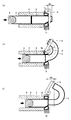
図2は、両ネック付きエルボを1行程からなる縮径加工と曲げ加工によって製造する方法を説明する図であり、(a)は先端側ネックの成形プロセスを示し、(b)は曲げ部の成形プロセスを示し、(c)は後端側ネックの成形プロセスを示す。ネック付きエルボ2の成形加工には、素管3を案内するガイドチューブ4と、素管3を挿入側から逐次または連続的に押し抜く装置5とを備えて、偏芯ダイス1bを用いた縮径加工に引き続き、素管3の管端を曲げアーム6でクランプすることにより曲げ加工を行う。
FIG. 2 is a view for explaining a method of manufacturing an elbow with both necks by a diameter reduction process and bending process consisting of one stroke, (a) shows a forming process of the front end side neck, and (b) shows a bending part. The molding process is shown, and (c) shows the molding process of the rear end side neck. For forming the
先端側のネック成形は、曲げアーム6で素管の管端をクランプすることなくネック長さN1に相当する直管部を押し抜く(図2(a))。次に、曲げ部の成形は、素管3の管端を曲げアーム6でクランプし曲げ加工に移行し、所定の曲げ角度に至るまで曲げ加工を行う(図2(b))。さらに、後端側のネック成形は、曲げ加工が所定の曲げ角度に至るまで進行したのち、素管3の管端から曲げアーム6のクランプを開放し、ネック長さN2の直管部を押し抜く(図2(c))。
In the neck formation on the distal end side, the straight pipe portion corresponding to the neck length N1 is pushed out without clamping the pipe end of the raw pipe with the bending arm 6 (FIG. 2A). Next, the bending portion is formed by clamping the tube end of the
前記図2に示す成形方法によれば、ネック付きエルボを効率的に製造することができるが、ネック部における寸法特性が悪化し、特に偏肉の発生が顕著になる。また、曲げ加工された管の内周側では圧縮応力が作用することから、内周側の肉厚は厚くなるとともに、内周側でしわを発生し易い。 According to the molding method shown in FIG. 2, an elbow with a neck can be efficiently manufactured, but the dimensional characteristics at the neck portion are deteriorated, and the occurrence of uneven thickness is particularly remarkable. Further, since compressive stress acts on the inner peripheral side of the bent tube, the inner peripheral side is thicker and wrinkles are likely to occur on the inner peripheral side.
さらに、偏芯ダイス出側に配置された曲げアームを用いた曲げ加工では、偏芯ダイスから押し抜かれた後、曲げ加工の進捗にともなって曲げ部に加わる曲げモーメントが増大する。このため、曲げ部に新たな塑性変形が生じることから、局所扁平が生じ易くなる。 Further, in the bending process using the bending arm arranged on the eccentric die exit side, the bending moment applied to the bending portion increases as the bending process progresses after being pushed out from the eccentric die. For this reason, since a new plastic deformation arises in a bending part, it becomes easy to produce local flatness.
本発明は、このようなネック付きエルボの製造方法における問題に鑑みてなされたものであり、ネック部および曲げ部の全長に亘り肉厚変動(偏肉)をなくすとともに、曲げ部におけるしわ発生や局所扁平を抑制し、寸法特性や品質特性に優れ、高能率生産に最適なネック付きエルボの製造方法を提供することを目的としている。 The present invention has been made in view of the problems in the method of manufacturing such an elbow with a neck, and eliminates fluctuations in thickness (uneven thickness) over the entire length of the neck portion and the bent portion, The purpose is to provide a method for producing an elbow with a neck that suppresses local flattening, has excellent dimensional characteristics and quality characteristics, and is optimal for high-efficiency production.
本発明者らは、前記の課題を解決するため、押し通し縮径曲げによるエルボ成形加工について検討した結果、適切に対称ダイスと偏芯ダイスを切り替え、同時に偏芯ダイスを適正に配置することにより、素管を押し抜いて縮径加工と同時に曲げ加工を施すことにより、ネック部および曲げ部の全長に亘り偏肉をなくすことができ、両ネックまたは片ネックのいずれを形成するのに拘わらず、1行程からなる効率的な成形プロセスにより、ネック付きエルボを製造できることに着目した。 In order to solve the above-mentioned problems, the present inventors have examined the elbow molding process by push-through diameter reduction bending.As a result, by appropriately switching between a symmetrical die and an eccentric die, and simultaneously arranging the eccentric die properly, By extruding the raw tube and bending at the same time as the diameter reduction processing, uneven thickness can be eliminated over the entire length of the neck portion and the bending portion, regardless of whether both necks or one neck is formed, It was noted that an elbow with a neck could be manufactured by an efficient molding process consisting of one stroke.
図3は、全長に亘り偏肉のないネック付きエルボを成形加工するプロセスを模式的に説明する図であり、(a)はネック部の成形プロセスを示し、(b)は曲げ部の成形プロセスを示している。図3(a)に示すように、ネック部の成形プロセスでは、対称ダイス1aを用い周方向に均一なダイス角度αで縮径加工を行い、その後も曲げ加工を加えることなく所定長さの直管部を押し抜く。このため、ネック部では素管肉厚を周方向に均等に増肉することが可能であり、成形加工にともなう偏肉発生をなくすことができる。
FIG. 3 is a diagram schematically illustrating a process of forming an elbow with a neck having no unevenness over the entire length, wherein (a) shows a forming process of the neck part, and (b) shows a forming process of the bent part. Is shown. As shown in FIG. 3A, in the forming process of the neck portion, the
図3(b)に示す曲げ部の成形プロセスでは、対称ダイス1aを偏芯ダイス1bに切り換えて縮径加工を行い、引き続き所定の曲げ角度に至るまで曲げ加工を施す。対称ダイス1aから偏芯ダイス1bに切り替えるのは、対称ダイス1aをダイス傾斜角θで傾斜させることにより、偏芯ダイス1bを構成することができる。偏芯ダイス1bに切り換えることにより、偏芯ダイス1bのA部におけるダイス角度βは(α+θ、ただし、θ<α)となる。
In the bending part forming process shown in FIG. 3B, the
このとき、偏芯ダイス1bのダイス角度βの大きいA部が曲げ外周側に位置するように、ダイス角度βの小さいB部が曲げ内周側に位置するように配置することにより、素管3の縮径加工にともない、A部では材料が主に塑性変形し外径が縮み肉厚が増えるのに対し、B部では材料の塑性変形そのものが小さく肉厚変動は殆ど生じない。このため、引き続いて曲げ加工を行うことにより、曲げ外周側に位置するA部では縮径加工による増肉と曲げ加工による減肉とを相殺させ減肉を少なくできる。
At this time, the
次に、後端側ネック部を成形する場合には、前記図3(a)に示すように、偏芯ダイス1bを対称ダイス1aに切り替えて、対称ダイス1aによる周方向に均一なダイス角度αで縮径加工を行い、その後も曲げ加工を加えることなく所定長さの直管部を押し抜く。これにより、後端側ネック部の成形加工にともなう偏肉発生をなくすことができる。
Next, when the rear end side neck portion is molded, as shown in FIG. 3A, the
偏芯ダイスを用いて縮径加工を行う場合に、ダイス穴径の入側中心軸と出側中心軸とには偏芯Hが生じる。このため、図3(b)に示すように、曲げ部の成形プロセスで偏芯ダイスを用いて縮径加工を行う際に、ダイス穴径の出側中心軸と素管のパスラインと一致させ、ダイス穴径の入側中心軸を素管のパスラインより偏芯Hを下方に移動させる。 When diameter reduction processing is performed using an eccentric die, eccentricity H is generated between the entrance side central axis and the exit side central axis of the die hole diameter. For this reason, as shown in FIG. 3B, when the diameter reduction process is performed using an eccentric die in the bending portion forming process, the exit side central axis of the die hole diameter is matched with the pass line of the raw pipe. Then, the eccentric H is moved downward from the pass line of the raw pipe along the entrance-side central axis of the die hole diameter.
曲げ部の成形プロセスで縮径加工を行う場合の偏芯Hの修正法として、図4に示すように、曲げ部の成形プロセスで縮径加工を行う際に、偏芯ダイスのダイス穴径の入側中心軸と素管のパスラインと一致させ、ダイス穴径の出側中心軸を素管のパスラインより偏芯Hを上方に移動させる方式を採用することができる。 As shown in FIG. 4, as a method of correcting the eccentricity H when the diameter reduction processing is performed in the bending portion forming process, when the diameter reduction processing is performed in the bending portion forming process, the die hole diameter of the eccentric die is changed. It is possible to adopt a method in which the eccentric center H is moved upwardly from the pass line of the raw pipe by making the inlet side central axis coincide with the pass line of the raw pipe and the outgoing center axis of the die hole diameter.
上記図3では、両ネック付きエルボ製品を対象として成形加工プロセスを説明したが、その成形加工プロセス内容は両ネック付きエルボ製品に限定されるものではなく、片ネック付きエルボ製品の成形加工にも適用できるものである。 In FIG. 3 described above, the molding process has been described for the elbow product with both necks. However, the content of the molding process is not limited to the elbow product with both necks, but also for the elbow product with one neck. Applicable.
ところで、上記図3で示す成形加工プロセスでは、曲げ部の成形プロセスで縮径加工と曲げ加工を組み合わせることにより、組み合わせ応力の効果が生じ、所要の曲げモーメントを小さくすることができるが、偏芯ダイスの出側において、曲げ加工の進捗にともなって曲げ部に加わる曲げモーメントが増大することがある。 By the way, in the molding process shown in FIG. 3, the combined stress effect is produced by combining the diameter reduction process and the bending process in the bending part molding process, and the required bending moment can be reduced. On the exit side of the die, the bending moment applied to the bent portion may increase with the progress of the bending process.
例えば、エルボ製品の曲げ加工の中間過程で曲げモーメントが最大になる現象が現れると、偏芯ダイスから押し抜かれた素管に新たな塑性変形が生じることになる。このため、エルボ製品の曲げ部に局所扁平が生じ易くなる。 For example, if a phenomenon in which the bending moment is maximized in the intermediate process of elbow product bending, a new plastic deformation occurs in the blank tube pushed out of the eccentric die. For this reason, it becomes easy to produce local flatness in the bending part of an elbow product.
さらに、曲げ部の内周側に発生するしわは、曲げ加工時の圧縮応力に起因するものである。このため、曲げ加工に要する曲げモーメントを抑制できれば、曲げ外周側の引張応力および曲げ内周側の圧縮応力を小さくでき、圧縮応力に起因する曲げ内周側に発生するしわを防止できる。 Furthermore, wrinkles generated on the inner peripheral side of the bent portion are caused by compressive stress during bending. Therefore, if the bending moment required for the bending process can be suppressed, the tensile stress on the outer periphery side of the bending and the compressive stress on the inner periphery side of the bending can be reduced, and wrinkles generated on the inner periphery side of the bending due to the compressive stress can be prevented.
通常、ネック付きエルボの成形加工には、素管を逐次または連続的に押し抜きながら、曲げ加工手段として旋回用の曲げアームを用い、素管の管端をクランプする方式が用いられる。この場合に、曲げ加工にともなう曲げモーメントは、曲げアーム旋回中心の配置条件、および曲げアームの旋回速度と押し抜き速度との比で示される速度比λの影響を受けることになる。 In general, the elbow with a neck is formed by a method of clamping a pipe end of a pipe using a bending arm for turning as a bending means while pushing the pipe sequentially or continuously. In this case, the bending moment accompanying the bending process is affected by the arrangement condition of the bending arm turning center and the speed ratio λ indicated by the ratio of the bending arm turning speed and the punching speed.
本発明は、上記図3に示すネック付きエルボを1行程で成形加工するプロセスを前提とする検討結果や知見に基づいて完成されたものであり、下記(1)および(2)のネック付きエルボの製造方法を要旨としている。 The present invention has been completed on the basis of the examination results and knowledge based on the process of forming the neck elbow shown in FIG. 3 in one stroke, and includes the following elbows (1) and (2). The manufacturing method is the gist.
(1)ガイドチューブに挿入された素管を挿入側から逐次または連続的に押し抜きながら、対称ダイスを用いて縮径加工するネック部成形プロセスと、偏芯ダイスに切り換えて縮径加工し、前記素管を曲げアームで保持して所定の曲げ角度に至るまで曲げ加工する曲げ部成形プロセスとを組み合わせてネック付きエルボを製造する方法であって、前記曲げ部成形プロセスにおいて、縮径加工により前記素管の曲げ外周側の肉厚を曲げ内周側の肉厚に比べて増肉させると同時に、前記曲げアームの旋回中心を偏芯ダイスの出側先端位置よりダイス入側に移動させた位置とし、所定のオフセット量Osを設けて曲げ加工を施すことを特徴とするネック付きエルボの製造方法である。 (1) Neck part forming process in which diameter reduction processing is performed using a symmetric die while sequentially or continuously pushing out the raw tube inserted in the guide tube, and the diameter reduction processing is performed by switching to an eccentric die, A method of manufacturing an elbow with a neck in combination with a bending part forming process in which the raw tube is held by a bending arm and bent to a predetermined bending angle, and in the bending part forming process, At the same time as increasing the thickness of the bending pipe on the outer peripheral side compared to the thickness on the inner side of the bending, the turning center of the bending arm was moved from the exit end position of the eccentric die to the die entry side. This is a method of manufacturing an elbow with a neck, characterized in that it is bent at a position and provided with a predetermined offset amount Os.
(2)上記(1)のネック付きエルボの製造方法は、前記曲げアームの旋回中心と偏芯ダイスの出側先端位置との距離で示されるオフセット量Os(mm)と、偏芯ダイスの仕上直径d(mm)との関係が下記(1)式を満足するのが望ましい。
Os/d=0.09〜0.18 ・・・ (1)
(2) The manufacturing method of the elbow with a neck of (1) described above includes the offset amount Os (mm) indicated by the distance between the turning center of the bending arm and the exit end position of the eccentric die, and the finish of the eccentric die. It is desirable that the relationship with the diameter d (mm) satisfies the following formula (1).
Os / d = 0.09-0.18 (1)
さらに、安定して扁平やしわ発生をなくすために、曲げアームの旋回速度Vφ(R・ω)と素管の押し抜き速度Vw(mm/s)との比で示される速度比λ(Vφ/Vw)を0.9〜1.1の範囲で管理するのが望ましい。速度比λ(Vφ/Vw)がこの範囲を外れる場合、すなわち曲げアーム旋回速度Vφが過度に遅かったり、または速かったりすると、扁平やしわ発生をし易いことによる。さらに、また旋回アームに過度の荷重が働くことから、設備保全上からも望ましくない。 Furthermore, in order to eliminate the occurrence of flatness and wrinkles stably, the speed ratio λ (Vφ / V) expressed by the ratio of the bending arm turning speed Vφ (R · ω) and the blank tube punching speed Vw (mm / s). It is desirable to manage Vw) in the range of 0.9 to 1.1. If the speed ratio λ (Vφ / Vw) is out of this range, that is, if the bending arm turning speed Vφ is excessively slow or fast, flatness and wrinkles are likely to occur. Furthermore, since an excessive load acts on the swivel arm, it is not desirable from the viewpoint of equipment maintenance.
本発明のネック付きエルボの製造方法によれば、適切に対称ダイスと偏芯ダイスを切り替え、同時に偏芯ダイスを適正に配置することにより、素管を押し抜いて縮径加工し曲げ加工を施すとともに、曲げアームのオフセット量(旋回中心と偏芯ダイスの出側先端位置との距離)を適切に選択し、さらに速度比(曲げアームの旋回速度と押し抜き速度の比)を制御することにより、両ネックまたは片ネックを形成するに拘わらず、高能率に製造することができる。 According to the method of manufacturing an elbow with a neck of the present invention, by appropriately switching between a symmetrical die and an eccentric die, and simultaneously arranging the eccentric die appropriately, the raw tube is pushed out to reduce the diameter and perform bending. At the same time, by properly selecting the offset amount of the bending arm (distance between the turning center and the exit tip position of the eccentric die), and further controlling the speed ratio (ratio between the bending arm turning speed and the punching speed) In spite of forming both necks or one neck, it can be manufactured with high efficiency.
しかも、得られたネック付きエルボ製品は、ネック部および曲げ部の全長に亘り偏肉をなくすとともに、曲げ部におけるしわ発生や局所扁平を抑制し、優れた寸法特性や品質特性を確保することができる。 In addition, the resulting elbow-equipped elbow product eliminates uneven thickness over the entire length of the neck and bend, and suppresses wrinkling and local flatness in the bend, ensuring excellent dimensional characteristics and quality characteristics. it can.
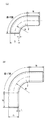
図5は、本発明が対象とするネック付きエルボ製品の外観形状を示す図であり、(a)は片ネック付きエルボ製品を、(b)は両ネック付きエルボ製品を示している。ネック付きエルボ2の形状は軸心を基準とする曲率半径R並びに外径D、内径および肉厚tで規定されており、用途によってロングエルボ(曲率半径Rが1.5×外径D)、またはショートエルボ(曲率半径Rが外径D)に区分される。
FIGS. 5A and 5B are views showing the external shape of a necked elbow product to which the present invention is applied. FIG. 5A shows an elbow product with one neck and FIG. 5B shows an elbow product with both necks. The shape of the
図5(a)に示す片ネック付きエルボ2は、曲げ部の片端に溶接施工用の直管からなる長さNのネック部を設けており、図5(b)に示す両ネック付きエルボ2は、曲げ部の両端に溶接施工用の直管からなる長さNのネック部を設ける。
An
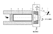
図6は、本発明のネック付きエルボの製造方法を実施するための模式的な装置構成例を示す図である。素管3を挿入するガイドチューブ4と素管3を挿入側から逐次または連続的に押し抜くための押し抜き装置5が配置される。そして、ガイドチューブ4の先端側にダイスタンド7が設けられており、このダイスタンド7に縮径加工を施すためのダイス装置1と、曲げ加工を施す曲げ手段として曲げアーム6が配置される。
FIG. 6 is a diagram showing a schematic apparatus configuration example for carrying out the method for manufacturing an elbow with a neck according to the present invention. A
ダイス装置1は傾斜機構を備えており、ネック部または曲げ部の成形プロセス切替にともなって、対称ダイスと偏芯ダイスとの切替を行う。対称ダイスを用いて縮径加工する場合は、素管肉厚は周方向に均等に増肉される。一方、偏芯ダイスを用いて縮径加工する場合は、偏芯ダイスのダイス角度βが大きい部位が曲げ外周側に位置し、ダイス角度βの小さい部位が曲げ内周側に位置するように配置され、素管肉厚は曲げ外周側において曲げ内周側に比べて増肉される。 The die apparatus 1 includes an inclination mechanism, and performs switching between a symmetric die and an eccentric die in accordance with switching of the forming process of the neck portion or the bent portion. In the case of reducing the diameter using a symmetric die, the thickness of the raw tube is increased uniformly in the circumferential direction. On the other hand, when diameter reduction processing is performed using an eccentric die, the eccentric die is arranged so that the portion where the die angle β is large is located on the bending outer peripheral side and the portion where the die angle β is small is located on the bending inner peripheral side. The wall thickness of the blank tube is increased on the outer peripheral side of the bending as compared with the inner peripheral side of the bending.
曲げアーム6は、ダイス装置1の出側領域に配置され、ダイスタンド7に固定される。このとき、曲げアーム6は、旋回中心を偏芯ダイスの出側先端位置よりダイス入側に移動させた位置とし、所定のオフセット量Osを設けて配置される。曲げアーム6の先端には、図示しないが、素管3を保持するためのアームクランプが設けられる。アームクランプは、ネック部または曲げ部の成形プロセス切替にともない、保持または開放の操作を繰り返す。
The bending
さらに、ダイスタンド7には、偏芯ダイスを用いて縮径加工を行う場合に、偏芯Hを修正するため、ダイス装置1および曲げアーム6と連動して昇降可能な装置が設置される。
Further, the die stand 7 is provided with a device capable of moving up and down in conjunction with the die device 1 and the
素材鋼管から設計寸法に切断された素管3は、ガイドチューブ4に挿入され、ガイドチューブ4の後端側に配置された押し込み装置5の油圧シリンダーの作動によって、押し抜き速度Vw(mm/s)でダイス装置1に押し込まれる。
The
先端側ネック部の縮径加工のプロセスでは、対称ダイスを用いて素管肉厚を周方向に均等に増肉し、曲げアーム6のアームクランプで素管を保持することなく所定長さの直管部を押し抜く。このため、先端側ネック部では、成形加工にともなう偏肉を発生することがない。
In the process of reducing the diameter of the neck on the front end side, the wall thickness of the pipe is uniformly increased in the circumferential direction by using a symmetric die, and the straight pipe of a predetermined length is not held by the arm clamp of the
曲げ部の縮径加工のプロセスでは、対称ダイスを偏芯ダイスに切り換えるため、ダイス傾斜角度θが設定され、これと連動してダイスタンド7が偏芯Hを修正すると同時に、曲げアーム6のアームクランプが素管3を保持し、曲げアーム6は旋回速度Vφ(R・ω)で、所定の曲げ角度φに至るまで曲げ加工を施す。
In the process of reducing the diameter of the bending portion, the die inclination angle θ is set to switch the symmetric die to the eccentric die, and the die stand 7 corrects the eccentricity H in conjunction with this, and at the same time, the arm of the
このときの曲げ部の縮径加工のプロセスでは、縮径加工された素管3は、偏芯ダイスのダイス角度βが大きい部位で増肉加工され、その後の曲げ加工にともなう減肉と相殺されるため、肉厚変動が小さくなる。
In the process of reducing the diameter of the bent portion at this time, the diameter-reduced
後端側ネック部の縮径加工プロセスでは、曲げアーム6が所定の曲げ角度φに達した後、偏芯ダイスから対称ダイスに切り換えるため、ダイス傾斜角度θをゼロ(零)に設定し、これと連動してダイスタンド7を下降させ、偏芯Hをゼロ(零)にすると同時に、曲げアーム6のアームクランプによる素管の保持を開放し、所定長さのネック部を押し抜く。
In the process of reducing the diameter of the rear end side neck portion, the die tilt angle θ is set to zero (zero) in order to switch from the eccentric die to the symmetric die after the
本発明のネック付きエルボの製造方法では、上記図6に示す装置構成において、曲げアームの旋回中心を偏芯ダイスの出側先端位置よりダイス入側に移動させた位置に配置し、曲げアームの旋回中心と偏芯ダイスの出側先端位置との距離で示されるオフセット量Osを設ける。 In the method of manufacturing an elbow with a neck according to the present invention, in the apparatus configuration shown in FIG. 6, the turning center of the bending arm is arranged at a position moved from the exit end position of the eccentric die to the die entry side. An offset amount Os indicated by the distance between the turning center and the exit end position of the eccentric die is provided.
オフセット量Osを適切に選択して曲げ加工を施すことにより、偏芯ダイスから押し抜かれた素管に付加される曲げモーメントを増大させることがない。このため、偏芯ダイス出側を通過した素管に新たな塑性変形が生じることがなく、曲げ加工にともなう扁平変形が解消され、曲げ部に局所扁平が発生することを防止できる。同様に、曲げ内周側の圧縮応力を低減できるので、圧縮応力に起因するしわ発生を防止できる。 By appropriately selecting the offset amount Os and performing the bending process, the bending moment applied to the blank pipe pushed out from the eccentric die is not increased. Therefore, new plastic deformation does not occur in the raw pipe that has passed through the eccentric die outlet side, flat deformation accompanying bending is eliminated, and local flatness can be prevented from occurring in the bent portion. Similarly, since the compressive stress on the inner side of the bending can be reduced, wrinkles caused by the compressive stress can be prevented.
適切なオフセット量Osは、素管の押し抜き寸法との関係が確認されており、曲げアームのオフセット量Os(mm)と、偏芯ダイスの仕上直径d(mm)との関係が下記(1)式を満足するのが望ましい。
Os/d=0.09〜0.18 ・・・ (1)
The appropriate offset amount Os has been confirmed to be related to the punching dimension of the raw tube, and the relationship between the offset amount Os (mm) of the bending arm and the finishing diameter d (mm) of the eccentric die is as follows (1) It is desirable to satisfy the formula.
Os / d = 0.09-0.18 (1)
上記(1)式において、Os/d値が0.09未満であると、偏芯ダイスから押し抜かれた素管に付加される曲げモーメントの増加が見られ、新たな塑性変形が生じ曲げ加工にともなう変形により、曲げ部に局所扁平が発生し易くなる。 In the above formula (1), if the Os / d value is less than 0.09, an increase in the bending moment applied to the blank pipe pushed out from the eccentric die is observed, and new plastic deformation occurs, resulting in bending. Due to the accompanying deformation, local flattening easily occurs in the bent portion.
一方、上記Os/d値が0.18を超えるようになると、偏芯ダイスから押し抜き後、曲げモーメントの増大は回避できるが、曲げ内周側にしわの起点が生じ、曲げ部にしわが発生し易くなる。 On the other hand, if the Os / d value exceeds 0.18, an increase in the bending moment can be avoided after punching out from the eccentric die, but a wrinkle starting point occurs on the inner circumference side of the bend, and wrinkles occur in the bent portion. It becomes easy to do.
本発明のネック付きエルボの製造方法では、曲がり部に発生する扁平を軽減し、同時にしわ発生をなくすために、曲げアームの旋回速度Vφ(R・ω)と素管の押し抜き速度Vw(mm/s)との比で示される速度比λ(Vφ/Vw)を0.9〜1.1で稼働させるのが望ましい。すなわち、速度比λ(Vφ/Vw)がこの範囲を外れる場合、具体的には、曲げアーム旋回速度Vφが過度に遅かったり、または速かったりする場合には、扁平やしわ発生をし易く、また旋回アームに過度の荷重が働くことから、設備保全上も望ましくない。 In the method of manufacturing an elbow with a neck according to the present invention, in order to reduce the flatness generated in the bent portion and eliminate wrinkles at the same time, the turning speed Vφ (R · ω) of the bending arm and the punching speed Vw (mm It is desirable to operate at a speed ratio λ (Vφ / Vw) represented by a ratio of 0.9 to 1.1. That is, when the speed ratio λ (Vφ / Vw) is out of this range, specifically, when the bending arm turning speed Vφ is excessively slow or fast, flatness and wrinkles are likely to occur. Since an excessive load acts on the swivel arm, it is not desirable for equipment maintenance.
前記図6に示す装置構成例からなる押し通し装置を用いて、寸法が外径60.5mm×肉厚3.8mm×長さ400mmである素管(炭素鋼)を準備し、偏芯ダイスによる押し抜き仕上寸法が55mmとなる両ネック付きエルボを製造した。このときの成形加工による縮径率は10%に相当する。 Using a push-through device comprising the device configuration example shown in FIG. 6, a raw tube (carbon steel) having an outer diameter of 60.5 mm, a wall thickness of 3.8 mm, and a length of 400 mm is prepared and pushed by an eccentric die. An elbow with both necks with a blanking dimension of 55 mm was produced. In this case, the reduction ratio by the forming process corresponds to 10%.
ダイス半角αが7.5°の対称ダイスを用い、素管の押し抜き速度Vwを2.5mm/sで一定として、ネック部の成形加工を行った。次いで曲げ部の成形加工の開始と同時にダイスを傾斜し、傾斜角度θ=αとして偏芯ダイスに切り替えた。このときの曲げアームの旋回速度Vφ(R・ω)を制御し、速度比λ(Vφ/Vw)と曲げアームのオフセット量Os(mm)を設定した。 Using a symmetric die having a die half angle α of 7.5 °, the punching speed Vw of the raw tube was constant at 2.5 mm / s, and the neck portion was formed. Next, the die was tilted simultaneously with the start of the bending process, and the tilt angle was changed to θ = α to switch to an eccentric die. The turning speed Vφ (R · ω) of the bending arm at this time was controlled, and the speed ratio λ (Vφ / Vw) and the bending arm offset amount Os (mm) were set.
本実施例では、先端側ネック部の長さ100mmを縮径加工し、次いで偏芯ダイスに切り替え、曲げアームで素管をクランプして所定の曲げ角度に至るまで曲げ加工を行い、曲げ加工後はダイス傾斜を戻し対称ダイスに切り替えて後端側ネック部を縮径加工し、曲がり部の扁平率の測定、並びに局所扁平およびしわ発生の評価を行った。 In this embodiment, the tip side neck portion is reduced in diameter by 100 mm, then switched to an eccentric die, the element tube is clamped by a bending arm, and bending is performed until a predetermined bending angle is obtained. Changed the slope of the die back to a symmetrical die, reduced the diameter of the neck at the rear end, measured the flatness of the bent portion, and evaluated the occurrence of local flatness and wrinkles.
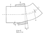
図7は、ネック付きエルボ成形加工後の測定位置を示す図である。該当する測定位置での短径d1および長径d2から平均径d0を算出して、下記(2)より扁平率Frを求めた。算出された扁平率Frの結果および評価結果を表1に示す。
Fr(%)={(d2−d1)/d0}×100 ・・・ (2)
FIG. 7 is a diagram illustrating a measurement position after the elbow with neck forming process. The average diameter d0 was calculated from the short diameter d1 and the long diameter d2 at the corresponding measurement position, and the flattening ratio Fr was obtained from the following (2). Table 1 shows the calculated flatness Fr and the evaluation results.
Fr (%) = {(d2-d1) / d0} × 100 (2)
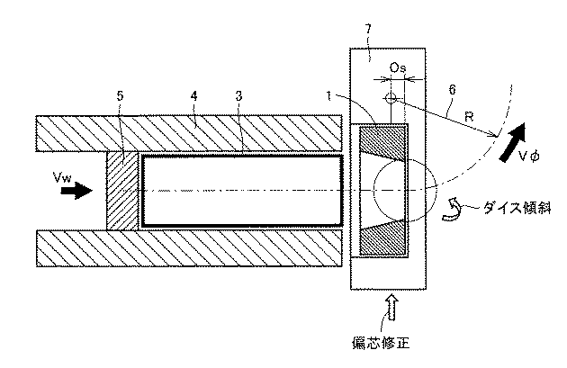
表1の結果から、オフセット量Osを設けない場合には(試験No.1、2)、曲げ加工の中間過程において曲げモーメントが大きくなって、扁平率が増大し、曲げ部に局所扁平が観察された。 From the results of Table 1, when the offset amount Os is not provided (Test Nos. 1 and 2), the bending moment increases in the intermediate process of bending, the flatness increases, and local flatness is observed in the bent portion. It was done.
一方、オフセット量Osを大きくしすぎて、Os/d値が0.27になると(試験No.7、8)、ダイス出側位置の曲げ部内周側にしわ発生があった。
これに対し、本発明で規定するOs/d値が0.09〜0.18の範囲においては(試験No.3〜6)、いずれも曲げ加工の中間過程において曲げモーメントの増加が抑制され、扁平率Frは20%未満に低減されるとともに、しわ発生は観察されなかった。
On the other hand, when the offset amount Os was increased too much and the Os / d value reached 0.27 (Test Nos. 7 and 8), wrinkles occurred on the inner peripheral side of the bent portion at the die exit side position.
On the other hand, when the Os / d value specified in the present invention is in the range of 0.09 to 0.18 (test Nos. 3 to 6), increase in bending moment is suppressed in the intermediate process of bending, The flattening ratio Fr was reduced to less than 20%, and wrinkle generation was not observed.
本実施例では、扁平率Frの測定と同時に、縮径加工された素管が偏芯ダイスのダイス角度βが大きい部位で増肉加工され、その後の曲げ加工にともなう減肉と相殺され、肉厚変動が小さくなり、偏肉率が6%以下に抑制されていることを確認している。 In this example, simultaneously with the measurement of the flattening ratio Fr, the diameter-reduced element pipe is increased in thickness at a portion where the die angle β of the eccentric die is large, and is offset with the decrease in thickness due to subsequent bending. It has been confirmed that the thickness variation is reduced and the thickness deviation rate is suppressed to 6% or less.
本発明のネック付きエルボの製造方法によれば、適切に対称ダイスと偏芯ダイスを切り替え、同時に偏芯ダイスを適正に配置することにより、素管を押し抜いて縮径加工し曲げ加工を施すとともに、曲げアームのオフセット量(旋回中心と偏芯ダイスの出側先端位置との距離)を適切に選択し、さらに速度比(曲げアームの旋回速度と押し抜き速度の比)を制御することにより、両ネックまたは片ネックを形成するに拘わらず、高能率に製造することができる。 According to the method of manufacturing an elbow with a neck of the present invention, by appropriately switching between a symmetrical die and an eccentric die, and simultaneously arranging the eccentric die appropriately, the raw tube is pushed out to reduce the diameter and perform bending. At the same time, by properly selecting the offset amount of the bending arm (distance between the turning center and the exit tip position of the eccentric die), and further controlling the speed ratio (ratio between the bending arm turning speed and the punching speed) In spite of forming both necks or one neck, it can be manufactured with high efficiency.
しかも、得られたネック付きエルボ製品は、ネック部および曲げ部の全長に亘り偏肉をなくすとともに、曲げ部におけるしわ発生や局所扁平を抑制し、優れた寸法特性や品質特性を確保することができる。これによりエルボ配管に用いられるネック付きエルボの成形加工法として広く利用することができる。 In addition, the resulting elbow-equipped elbow product eliminates uneven thickness over the entire length of the neck and bend, and suppresses wrinkling and local flatness in the bend, ensuring excellent dimensional characteristics and quality characteristics. it can. Thereby, it can utilize widely as a shaping | molding processing method of the elbow with a neck used for elbow piping.
1:ダイス、ダイス装置、 1a:対称ダイス
1b:偏芯ダイス、 2:エルボ
3:素管、 4:ガイドチューブ
5:押し抜き装置、 6:曲げアーム
7:ダイスタンド
DESCRIPTION OF SYMBOLS 1: Die, die apparatus, 1a: Symmetrical die 1b: Eccentric die, 2: Elbow 3: Raw pipe, 4: Guide tube 5: Punching device, 6: Bending arm 7: Die stand
Claims (3)
前記対称ダイスをダイス穴径の入側中心軸と出側中心軸とが偏芯しているダイス(以下、「偏芯ダイス」という)に切り換えて縮径加工し、前記素管を曲げアームで保持して所定の曲げ角度に至るまで曲げ加工する曲げ部成形プロセスとを組み合わせてネック付きエルボを製造する方法であって、
前記曲げ部成形プロセスにおいて、縮径加工により前記素管の曲げ外周側の肉厚を曲げ内周側の肉厚に比べて増肉させると同時に、前記曲げアームの旋回中心を偏芯ダイスの出側先端位置よりダイス入側に移動させた位置とし、所定のオフセット量Osを設けて曲げ加工を施すことを特徴とするネック付きエルボの製造方法。 A die in which the central axis of the die hole diameter coincides with the central axis of the outlet side (hereinafter referred to as a “symmetrical die”) while the core tube inserted into the guide tube is sequentially or continuously pushed out from the insertion side. Neck part forming process to reduce the diameter using
The symmetric die is switched to a die having an eccentric center axis on the die hole diameter and an eccentric center axis on the die side (hereinafter referred to as “eccentric die”) to reduce the diameter, and the raw tube is bent with a bending arm. A method of manufacturing an elbow with a neck in combination with a bending part forming process of holding and bending to a predetermined bending angle,
In the bending part forming process, the wall thickness of the bending outer circumference side of the base pipe is increased compared with the thickness of the bending inner circumference side by reducing the diameter, and at the same time, the turning center of the bending arm is brought out of the eccentric die. A method of manufacturing an elbow with a neck, characterized in that a bending is performed by providing a predetermined offset amount Os at a position moved from the side tip position to the die entry side.
Os/d=0.09〜0.18 ・・・ (1) The relationship between the offset amount Os (mm) indicated by the distance between the turning center of the bending arm and the exit end position of the eccentric die satisfies the following formula (1). The manufacturing method of the elbow with a neck of Claim 1 characterized by the above-mentioned.
Os / d = 0.09-0.18 (1)
Priority Applications (1)
| Application Number | Priority Date | Filing Date | Title |
|---|---|---|---|
| JP2008217789A JP2010051990A (en) | 2008-08-27 | 2008-08-27 | Method of manufacturing necked elbow |
Applications Claiming Priority (1)
| Application Number | Priority Date | Filing Date | Title |
|---|---|---|---|
| JP2008217789A JP2010051990A (en) | 2008-08-27 | 2008-08-27 | Method of manufacturing necked elbow |
Publications (1)
| Publication Number | Publication Date |
|---|---|
| JP2010051990A true JP2010051990A (en) | 2010-03-11 |
Family
ID=42068469
Family Applications (1)
| Application Number | Title | Priority Date | Filing Date |
|---|---|---|---|
| JP2008217789A Pending JP2010051990A (en) | 2008-08-27 | 2008-08-27 | Method of manufacturing necked elbow |
Country Status (1)
| Country | Link |
|---|---|
| JP (1) | JP2010051990A (en) |
Cited By (7)
| Publication number | Priority date | Publication date | Assignee | Title |
|---|---|---|---|---|
| CN103464591A (en) * | 2013-09-09 | 2013-12-25 | 张家港保税区恒隆钢管有限公司 | Steel tube reducing mould |
| CN104043741A (en) * | 2014-06-27 | 2014-09-17 | 张家港保税区亚信汽车零部件科技有限公司 | Steel tube necking die |
| CN107511425A (en) * | 2017-08-23 | 2017-12-26 | 柳州劲胜科技有限公司 | Punched pipefitting necking die |
| CN109351853A (en) * | 2018-11-05 | 2019-02-19 | 南通江华热动力机械有限公司 | A kind of three-dimensional bending tube composite molding tooling |
| CN111203487A (en) * | 2020-01-09 | 2020-05-29 | 徐寿强 | Combined cone attached inclination angle necking machine |
| CN111570647A (en) * | 2020-05-27 | 2020-08-25 | 成都佰缇丽贸易有限公司 | Short pipe material necking machine |
| CN113290093A (en) * | 2020-02-21 | 2021-08-24 | 苏州工业园区良裕科技有限公司 | Method for realizing multiple bending by using pipe bender |
Citations (1)
| Publication number | Priority date | Publication date | Assignee | Title |
|---|---|---|---|---|
| JP2008173650A (en) * | 2007-01-16 | 2008-07-31 | Sumikin Kiko Kk | Elbow product with neck and method of manufacturing the same |
-
2008
- 2008-08-27 JP JP2008217789A patent/JP2010051990A/en active Pending
Patent Citations (1)
| Publication number | Priority date | Publication date | Assignee | Title |
|---|---|---|---|---|
| JP2008173650A (en) * | 2007-01-16 | 2008-07-31 | Sumikin Kiko Kk | Elbow product with neck and method of manufacturing the same |
Cited By (7)
| Publication number | Priority date | Publication date | Assignee | Title |
|---|---|---|---|---|
| CN103464591A (en) * | 2013-09-09 | 2013-12-25 | 张家港保税区恒隆钢管有限公司 | Steel tube reducing mould |
| CN104043741A (en) * | 2014-06-27 | 2014-09-17 | 张家港保税区亚信汽车零部件科技有限公司 | Steel tube necking die |
| CN107511425A (en) * | 2017-08-23 | 2017-12-26 | 柳州劲胜科技有限公司 | Punched pipefitting necking die |
| CN109351853A (en) * | 2018-11-05 | 2019-02-19 | 南通江华热动力机械有限公司 | A kind of three-dimensional bending tube composite molding tooling |
| CN111203487A (en) * | 2020-01-09 | 2020-05-29 | 徐寿强 | Combined cone attached inclination angle necking machine |
| CN113290093A (en) * | 2020-02-21 | 2021-08-24 | 苏州工业园区良裕科技有限公司 | Method for realizing multiple bending by using pipe bender |
| CN111570647A (en) * | 2020-05-27 | 2020-08-25 | 成都佰缇丽贸易有限公司 | Short pipe material necking machine |
Similar Documents
| Publication | Publication Date | Title |
|---|---|---|
| JP2010051990A (en) | Method of manufacturing necked elbow | |
| JP4826634B2 (en) | Manufacturing method of ultra-thin metal tube by cold rolling method | |
| TWI295201B (en) | ||
| CN106541253A (en) | A kind of production technology of steel pipe | |
| JP4774809B2 (en) | Manufacturing method of ultra-thin seamless metal tube by cold rolling method | |
| CA2743165C (en) | Method for producing seamless metallic tube by cold rolling | |
| JP2008173648A (en) | Method and apparatus for cold bending pipe, and elbow manufactured by the same method and apparatus | |
| JP2010131617A (en) | Method of manufacturing ultra-thin wall seamless metallic pipe using floating plug | |
| JP2014004626A (en) | Method of manufacturing different-diameter tubular component, and molding metal mold | |
| WO2002024366A1 (en) | Method of forming cold diametrally reducing roll for metal pipe and metal pipe formed by the method | |
| RU2474485C2 (en) | Method of combined pipe end upsetting | |
| JP2008221280A (en) | Pipe expanding method and pipe expanding apparatus of uoe steel pipe | |
| JPH09103819A (en) | Production for tube excellent in shape precision by using drawing and drawing tool | |
| JPH01245914A (en) | Manufacture of metallic pipe excellent in out-of-roundness of outer diameter | |
| CN207668243U (en) | A kind of processing unit (plant) of minor radius bending pipe fitting | |
| JP2008173650A (en) | Elbow product with neck and method of manufacturing the same | |
| CN216095642U (en) | Steel pipe forming device | |
| CN113798382B (en) | Processing method for thinning back accumulation of tee joint | |
| CN216126437U (en) | Die set for avoiding cracking of steel pipe welding position | |
| JP4213370B2 (en) | Method for producing annealed wire rod for cold working | |
| RU2119837C1 (en) | Method of making electrically welded limit-length tubes | |
| CN109675977B (en) | Thin-wall metal pipe bending method | |
| CN113976662A (en) | Steel pipe forming device | |
| WO2020029008A1 (en) | Separator plate forming method | |
| JP2003220419A (en) | Forming rolls and forming method |
Legal Events
| Date | Code | Title | Description |
|---|---|---|---|
| A621 | Written request for application examination |
Free format text: JAPANESE INTERMEDIATE CODE: A621 Effective date: 20100428 |
|
| A977 | Report on retrieval |
Free format text: JAPANESE INTERMEDIATE CODE: A971007 Effective date: 20120208 |
|
| A131 | Notification of reasons for refusal |
Effective date: 20120306 Free format text: JAPANESE INTERMEDIATE CODE: A131 |
|
| A02 | Decision of refusal |
Free format text: JAPANESE INTERMEDIATE CODE: A02 Effective date: 20120717 |