JP2010049361A - Numerical control device having theoretical machine position calculation means - Google Patents
Numerical control device having theoretical machine position calculation means Download PDFInfo
- Publication number
- JP2010049361A JP2010049361A JP2008211111A JP2008211111A JP2010049361A JP 2010049361 A JP2010049361 A JP 2010049361A JP 2008211111 A JP2008211111 A JP 2008211111A JP 2008211111 A JP2008211111 A JP 2008211111A JP 2010049361 A JP2010049361 A JP 2010049361A
- Authority
- JP
- Japan
- Prior art keywords
- machine position
- machine
- theoretical
- difference
- unit
- Prior art date
- Legal status (The legal status is an assumption and is not a legal conclusion. Google has not performed a legal analysis and makes no representation as to the accuracy of the status listed.)
- Granted
Links
Images


Abstract
Description
本発明は数値制御装置に関し、特に、理論的な機械位置と実際の機械位置の差分を常時検出することが可能な数値制御装置に関する。 The present invention relates to a numerical control device, and more particularly to a numerical control device that can always detect a difference between a theoretical machine position and an actual machine position.
数値制御装置は、加工プログラムに従って工作機械の工具や工作物(ワーク)の移動や回転などを制御し、工作機械に工作物(ワーク)を加工させる制御装置である。数値制御装置は、指令部1とサーボ制御部2とを有する。指令部1からの移動指令に基づいてサーボ制御部2はアンプ3を介してサーボモータ4を駆動制御する。サーボモータ4には、位置検出器5が取り付けられている(図7参照)。
The numerical control device is a control device that controls the movement or rotation of a tool or workpiece (work) of a machine tool according to a machining program, and causes the machine tool to process the workpiece (work). The numerical control device includes a
まず、指令部1について説明する。指令部1の加工プログラム100は、工作機械を制御しワークを加工するプログラムである。機械座標更新処理部101は、加工プログラム100を解析する解析手段101a、解析手段101aで解析された加工プログラム100の加工経路である位置データおよび送り速度を基に補間処理する補間手段101bを有する。
First, the
機械座標更新処理部101の補間手段101bの補間処理で得られた補間パルスによる移動指令は、加減速処理手段102により加減速処理がなされた後、サーボ制御部2に移動指令が出力される。
The movement command based on the interpolation pulse obtained by the interpolation processing of the
指令部1からの移動指令は、サーボ制御部2の位置偏差量加算手段200に入力する。位置偏差量加算手段200には、サーボモータ4に取り付けられている位置検出器5からのフィードバックパルス信号も入力する。位置偏差量加算手段200では、前記移動指令と前記フィードバック信号の差分演算がなされ、演算結果は位置偏差量レジスタ201に送られる。位置偏差量レジスタ201は、位置・速度・電流制御手段202および指令部1に位置偏差量を出力する。位置・速度・電流制御手段202は、位置・速度・電流制御によりアンプ3を制御しサーボモータ4を駆動する。上記指令部1に出力される位置偏差量を以下、位置偏差FBという。位置偏差FBは換言すると数値制御装置のサーボ制御部2で受け取った移動指令と実際の機械位置との差分である。
The movement command from the
指令部1は、この位置偏差FBを位置偏差監視手段111で常時監視している。そして、位置偏差監視手段111は、位置偏差FBに異常があると判断すると、軸移動停止手段110に対して指令する。該手段110は、軸移動の停止を行う処理を開始する。
The
位置偏差監視手段111には、位置偏差FBの異常を判断するための基準となる「許容される位置偏差」が予め設定されている。位置偏差FBは軸移動速度に依存して変化するため、前記許容される位置偏差は軸の最大速度から算出されている。位置偏差監視手段111は、前記許容される位置偏差を超える位置偏差FBが検出された場合に軸移動停止手段110に指令し、アラームを発生させて軸を停止させていた。 In the position deviation monitoring unit 111, an “allowable position deviation” serving as a reference for determining an abnormality in the position deviation FB is set in advance. Since the position deviation FB varies depending on the shaft movement speed, the allowable position deviation is calculated from the maximum speed of the shaft. When the position deviation FB exceeding the allowable position deviation is detected, the position deviation monitoring means 111 instructs the axis movement stopping means 110 to generate an alarm and stop the axis.
そのため、移動中の軸に何らかの異常により位置ずれが発生しても、位置偏差FBが許容される位置偏差以上になるまで、何らかの異常による位置ずれを検出できなかった。また、位置偏差FBは前述のとおりサーボ制御部2が受け取った指令と実際の機械位置(位置検出器5からのフィードバック情報)との差分であるため、指令部1に何らかの異常が発生し、不正な指令がサーボ制御部2に出力されたとしても、それを検出することはできなかった。
For this reason, even if a positional deviation occurs due to some abnormality in the moving shaft, the positional deviation due to any abnormality could not be detected until the positional deviation FB exceeds the allowable positional deviation. Further, since the position deviation FB is the difference between the command received by the
位置偏差に基づいて異常検出する技術として例えば特許文献1、特許文献2がある。特許文献1に開示される技術は、モータ回転速度が低速の場合でも、外力などで発生した異常(指令位置からのずれ)を短時間のうちに検出する技術である。
For example,
この技術は、サーボモータの実駆動と並行してサーボモータ駆動のシミュレーションを行う。実駆動で得られた位置偏差とシミュレーションで得られた位置偏差の差分を監視して、その差分が設定値を超えた場合にアラームを発生させる。 This technology performs a servo motor drive simulation in parallel with the actual drive of the servo motor. The difference between the position deviation obtained by actual driving and the position deviation obtained by simulation is monitored, and an alarm is generated when the difference exceeds a set value.
しかし、この技術は、指令部から与えられた指令値をサーボモータ部内でのみ処理するため、指令部に異常が発生してサーボ制御部に異常な値を指令しても、その異常を検知できない。また、異常の判断をサーボ制御部内で行うため、異常が発生した機械位置を正確に把握することは困難である。 However, since this technology processes the command value given from the command unit only within the servo motor unit, even if an error occurs in the command unit and an abnormal value is commanded to the servo control unit, the error cannot be detected. . Further, since the abnormality is determined in the servo control unit, it is difficult to accurately grasp the machine position where the abnormality has occurred.
また、特許文献2には、リミットスイッチを用いないで数値制御工作機械のオーバトラベルを検出する技術が開示されている。この技術は、速度指令から理論位置偏差を算出し、それを実位置偏差と比較する。
軸がオーバトラベルしてダンパに接触すると、実位置偏差が増大するので、理論位置偏差を超える値となる。理論位置偏差を超えるかを検出することでオーバトラベルを判断する。これにより、リミットスイッチを用いることなくオーバトラベルを検出する。 When the shaft overtravels and comes into contact with the damper, the actual position deviation increases, so that the value exceeds the theoretical position deviation. Overtravel is determined by detecting whether the theoretical position deviation is exceeded. Thereby, overtravel is detected without using a limit switch.
特許文献2に開示される技術は、物理的に設けられたダンパに接触することで発生する位置ずれの検出をリミットスイッチの代わりにするものである。ダンパに接触することで、必然的に発生する位置ずれをより早く検出するために理論位置偏差と実位置偏差の比較を行っており、指令位置や機械位置は考慮されていない。
The technique disclosed in
そこで本発明の目的は、数値制御装置の指令部が制御上発生する遅れを考慮して理論的な機械位置を求め、この理論的な機械位置と位置検出器から得た実際の機械位置の情報を比較することで、理論的な機械位置と実際の機械位置の差分を常時検出する機能を備えた数値制御装置を提供することである。 Accordingly, an object of the present invention is to obtain a theoretical machine position in consideration of a delay generated in the control of the command unit of the numerical control device, and information on the actual machine position obtained from the theoretical machine position and the position detector. Is to provide a numerical control device having a function of constantly detecting a difference between a theoretical machine position and an actual machine position.
本願の請求項1に係る発明は、機械を駆動する軸の制御を行うサーボ制御部へ軸移動を指令する指令部を有する数値制御装置において、前記サーボ制御部は、各軸の位置を検出する検出手段からの信号に基づき実際の機械位置を算出する実機械位置算出手段を備え、前記指令部は、機械座標指令位置から、加減速による出力の遅れ量、およびサーボ制御部の出力の遅れ量を差し引いた理論上の機械位置を算出する理論機械位置算出手段と、該理論機械位置算出手段で算出された値と前記サーボ制御部で検出された実際の機械位置との差を算出する機械位置差分算出手段と、該機械位置差分算出手段で算出した値を予め定められた値と比較する機械位置差分監視手段と、該機械位置差分監視手段で比較した値が予め定められた値を超えた時、軸移動を停止する手段とワーニングを出力する手段の少なくとも一方を備えた数値制御装置である。
The invention according to
請求項2は、外部入力信号あるいはNCプログラム指令により前記理論機械位置算出手段による理論機械位置の更新を停止することを特徴とする請求項1に記載の数値制御装置である。 According to a second aspect of the present invention, in the numerical control device according to the first aspect, the updating of the theoretical machine position by the theoretical machine position calculating means is stopped by an external input signal or an NC program command.
請求項3に係る発明は、前記機械位置差分算出手段で求めた値、あるいは該算出に使用した理論機械位置および実際の機械位置を記録する記録手段と、該記録手段に記録した値を出力する出力手段と、を有することを特徴とする請求項1または請求項2に記載の数値制御装置である。
The invention according to claim 3 outputs a value obtained by the machine position difference calculating means, a recording means for recording the theoretical machine position and the actual machine position used for the calculation, and a value recorded in the recording means. The numerical control device according to
本発明により、数値制御装置の指令部が制御上発生する遅れを考慮して理論的な機械位置を求め、この理論的な機械位置と位置検出器から得た実際の機械位置の情報とを比較することで、理論的な機械位置と実際の機械位置の差分を検出する機能を備えた数値制御装置を提供できる。 According to the present invention, a theoretical machine position is obtained in consideration of a delay generated in the control of the command unit of the numerical controller, and this theoretical machine position is compared with information on the actual machine position obtained from the position detector. By doing so, it is possible to provide a numerical control device having a function of detecting a difference between a theoretical machine position and an actual machine position.
本発明は、軸の移動速度によらず、一定の許容範囲を超えた差分が検出された場合に軸の移動を停止させることができる。さらに、機械的な外力、指令部、サーボ制御部を問わず、何らかの異常で理論的な機械位置と実際の機械位置に差が生じた場合、それを直ちに検知し、制御を停止させることで、従来よりも工作機械のダメージを少なくすることができる。 The present invention can stop the movement of the shaft when a difference exceeding a certain allowable range is detected regardless of the moving speed of the shaft. Furthermore, regardless of mechanical external force, command unit, servo control unit, if there is a difference between the theoretical machine position and the actual machine position due to some abnormality, it is immediately detected and the control is stopped, Damage to machine tools can be reduced as compared with conventional machines.
一般に、数値制御装置において、非常停止時にはフォローアップが行われており、外力による軸の移動に応じて指令部の機械位置が更新されている。本発明において理論的な機械位置はサーボ制御部の制御に用いられない。そのため、軸の制御に影響を与えずに、理論的な機械位置の更新を停止させることが可能である。この理論的な機械位置の更新停止で得られる情報は、フォローアップや制御上発生する遅れに伴う機械位置の更新の影響を受けない。 Generally, in a numerical control device, follow-up is performed at an emergency stop, and the machine position of the command unit is updated according to the movement of the shaft by an external force. In the present invention, the theoretical machine position is not used for control of the servo control unit. Therefore, the theoretical machine position update can be stopped without affecting the control of the shaft. The information obtained by the theoretical machine position update stop is not affected by the machine position update caused by the follow-up or control delay.
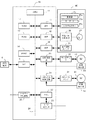
以下、本発明の実施形態を図面とともに説明する。図1は、本発明に係る理論機械位置と機械位置差分を算出する構成を説明する図である。数値制御装置は、背景技術で説明したように、指令部1とサーボ制御部2とを有する。指令部1からの移動指令に基づいてサーボ制御部2はアンプ3を介してサーボモータ4を駆動制御する。サーボモータ4には、位置検出器5が内蔵されている。場合によっては、軸が制御するテーブル側に位置検出器5を取り付けることができる。以下、サーボモータ4に位置検出器5が内蔵された実施形態を例として説明する。
Hereinafter, embodiments of the present invention will be described with reference to the drawings. FIG. 1 is a diagram illustrating a configuration for calculating a theoretical machine position and a machine position difference according to the present invention. As described in the background art, the numerical control device includes a
指令部1の加工プログラム100は、工作機械を制御しワークを加工するプログラムである。機械座標更新処理部101は、加工プログラム100を解析する解析手段101a、解析手段101aで解析された加工プログラム100の加工経路である位置データおよび送り速度等を基に補間処理する補間手段101bを有する。
The
補間手段101bの補間処理で得られた移動指令である補間パルスは、加減速処理手段102により加減速処理がなされた後、サーボ制御部2にパルス量である移動指令が出力される。
The interpolation pulse, which is a movement command obtained by the interpolation processing of the
機械座標更新処理部101は、各軸の現在位置が保存される現在位置レジスタACC1A(以下、単に「ACC1A」という)を備えている。ACC1Aには、数値制御装置の補間周期に同期して機械の各軸の移動量であるパルス量が加算手段ADD1Aにより加算され該レジスタACC1Aに保存される。
The machine coordinate
指令部1は、加減速処理による遅れ量を求める手段を備えている。加減速による遅れ量は、加減速処理手段102の入力と出力の差を積算した量である。加減速処理による遅れ量を求める手段は、加算手段ADD1Bと加算結果を一時的に記憶するレジスタであるアキュームレータACC1B(以下、「ACC1B」という)を備えている。加算手段ADD1Bには、加減速処理手段102への入力、加減速処理手段102からの出力、およびACC1Bからの出力が入力し、演算結果はACC1Bで一時的に記憶され、ACC1Bにはサンプリング時点における加減速による遅れ量が記憶される。
The
ここで、図3に示される直線型加減速制御を例にとって、加減速による遅れ量を説明する。なお、横軸は時間、縦軸は送り速度を表している。また、時定数τを40msec、補間周期Tを8msecとする。加減速処理手段102には、補間周期毎に補間手段101bから図3(a)に示される移動指令である補間パルスが入力する。加減速処理手段102は、入力した補間パルスを時定数τの40msecで加減速制御し、図3(b)に示される加減速制御された移動指令であるパルス量を出力する。加減速による遅れ量は、図3(b)の灰色部分に示されるように、送り速度が加速あるいは減速しているときに発生する。 Here, taking the linear acceleration / deceleration control shown in FIG. 3 as an example, the delay amount due to acceleration / deceleration will be described. The horizontal axis represents time, and the vertical axis represents the feed rate. The time constant τ is 40 msec and the interpolation period T is 8 msec. The acceleration / deceleration processing means 102 receives an interpolation pulse which is a movement command shown in FIG. 3A from the interpolation means 101b for each interpolation period. The acceleration / deceleration processing means 102 performs acceleration / deceleration control on the input interpolation pulse with a time constant τ of 40 msec, and outputs a pulse amount that is a movement command subjected to acceleration / deceleration control shown in FIG. The amount of delay due to acceleration / deceleration occurs when the feed rate is accelerating or decelerating, as shown in the gray portion of FIG.
指令部1は更に、理論機械位置算出手段103と機械位置差分算出手段104を備えている。これらに関してはサーボ制御部2について説明した後に説明する。また、図2や図5では、図1で説明した「指令位置」、「加減速による遅れ量」、および「実機械位置」に関する構成は記載を省略している。
The
次に、サーボ制御部2について説明する。サーボ制御部2に入力した移動指令は、位置偏差量加算手段200に入力する。位置偏差量加算手段200には、サーボモータ4に取り付けられている位置検出器5からのフィードバック信号も入力する。位置偏差量加算手段200では、前記移動指令と前記フィードバック信号の差分演算がなされ、演算結果は位置偏差量レジスタ201に送られる。位置偏差量レジスタ201は、位置・速度・電流制御手段202および指令部1に位置偏差量を出力する。位置・速度・電流制御手段202は、位置・速度・電流制御によりアンプ3を制御しサーボモータ4を駆動する。
Next, the
サーボ制御部2は、実機械位置算出手段203を備えている。実機械位置算出手段203は、軸に設置される位置検出器5からのフィードバック信号であるパルスを積算することにより「実際の機械位置」を算出する。
The
実機械位置算出手段203は、加算手段ADD2と加算結果を一時的に記憶するレジスタであるアキュームレータACC2(以下、「ACC2」という)を備えている。ADD2には、サンプリング周期毎に位置検出器5からの位置フィードバックデータとACC2に一時記憶したデータとが入力し、ADD2での加算結果はACC2で一時的に記憶され、ACC2にはサンプリング時点における実際の機械位置が記憶される。
The actual machine
次に、指令部1の理論機械位置算出手段103と機械位置差分算出手段104について説明する。理論機械位置算出手段103は、数1式に基づき軸の理論機械位置を算出する手段である。算出した理論機械位置は、機械位置差分算出手段104に出力される。
Next, the theoretical machine
理論機械位置=指令位置−(加減速による出力の遅れ量+位置偏差) (数1) Theoretical machine position = Command position-(Output delay due to acceleration / deceleration + Position deviation) (Equation 1)
機械位置差分算出手段104は、理論機械位置算出手段103で算出した理論機械位置と実機械位置算出手段203で算出した実機械位置により数式2に基づき軸の「機械位置差分」を算出する手段である。
The machine position difference calculating means 104 is a means for calculating the “machine position difference” of the axis based on the
機械位置差分=理論機械位置−実際の機械位置 (数2) Machine position difference = Theoretical machine position-Actual machine position (Equation 2)
前述したように、「実際の機械位置」はサーボモータ4に設置される位置検出器5からのフィードバック信号を積算することで求められ、サーボ制御部2に設けられる実機械位置算出手段203で算出される。
As described above, the “actual machine position” is obtained by integrating feedback signals from the
機械位置差分算出手段104で算出した「機械位置差分」は、軸の移動中を含め、常に”0”(ゼロ)を示すべき量である。その「機械位置差分」の値が”0”(ゼロ)でなくなるのは、軸制御に何らかの不都合や異常が発生したことを示す。 The “machine position difference” calculated by the machine position difference calculation means 104 is an amount that should always indicate “0” (zero), including during movement of the axis. That the “machine position difference” value is not “0” (zero) indicates that some inconvenience or abnormality has occurred in the axis control.
ここで、数1式で示される理論機械位置を算出するために用いられる「指令位置」、「加減速による出力の遅れ量」、および「位置偏差」の3つのデータについて説明する。
●指令位置
「指令位置」は、指令部が加工プログラムや手動運転などに従い、軸を制御して到達させようとする機械座標上のある位置を意味する。
Here, three data “command position”, “output delay amount due to acceleration / deceleration”, and “position deviation” used to calculate the theoretical machine position expressed by the
● Command position “Command position” means a certain position on the machine coordinates that the command unit tries to reach by controlling the axis according to the machining program or manual operation.
●加減速制御による遅れ量
「加減速制御による遅れ量」は、軸移動の開始時および減速時に機械系にショックや振動を与えないようにするために行われる加速、減速に関係し、指令された速度への加減速に伴って発生する前記指令位置に対する遅れを意味する。
Delay amount due to acceleration / deceleration control The delay amount due to acceleration / deceleration control is a command related to acceleration / deceleration performed to prevent shock and vibration from being applied to the mechanical system at the start of axis movement and deceleration. It means a delay with respect to the command position that occurs with acceleration / deceleration to a certain speed.
図4は、加減速制御を説明する図である。加減速制御には、図3を用いて説明した直線型加減速(図4(a)参照)や指数関数型加減速制御(図4(b)参照)、ベル型加減速(図示省略)など種々のものがある。横軸は時間、縦軸は速度を表している。工作機械などの各軸を駆動するサーボモータは数値制御装置などの制御装置で駆動制御される。サーボモータを急激に駆動もしくは停止させることは困難であるから、一般に移動指令に対して加減速制御を行って、加速時には移動指令を徐々に増大させ、また、減速時には徐々に移動指令を減少させるようにしている。加減速の制御を行うと出力の遅れ量が発生する。 FIG. 4 is a diagram for explaining acceleration / deceleration control. For acceleration / deceleration control, linear acceleration / deceleration (see FIG. 4A), exponential acceleration / deceleration control (see FIG. 4B), bell-type acceleration / deceleration (not shown), etc. described with reference to FIG. There are various things. The horizontal axis represents time, and the vertical axis represents speed. A servo motor for driving each axis of a machine tool or the like is driven and controlled by a control device such as a numerical control device. Since it is difficult to drive or stop the servo motor suddenly, generally, acceleration / deceleration control is performed on the movement command, and the movement command is gradually increased during acceleration, and the movement command is gradually decreased during deceleration. I am doing so. When acceleration / deceleration is controlled, output delay occurs.
図4(a)に示した直線型加減速の場合の「加減速による出力の遅れ量」を例にとって説明する。「加減速による出力の遅れ量」は、指令された速度への加減速に伴って発生する、上記指令位置に対する遅れを意味する。図4(a)では、灰色部分が「加減速による出力の遅れ量」に相当する。これは、加減速処理の種別により異なるものである。一例として、補間後直線加減速の場合の計算式(数式3)を示す。 A description will be given by taking the “output delay amount due to acceleration / deceleration” in the case of the linear acceleration / deceleration shown in FIG. The “delay amount of output due to acceleration / deceleration” means a delay with respect to the command position, which occurs with acceleration / deceleration to the commanded speed. In FIG. 4A, the gray portion corresponds to “the output delay amount due to acceleration / deceleration”. This differs depending on the type of acceleration / deceleration processing. As an example, a calculation formula (Formula 3) in the case of linear acceleration / deceleration after interpolation is shown.
Q=Ft*1/60*(1/2*Tc/1000) (数3)
Q:加減速による出力の遅れ量(mmまたはinch)
Ft:計算周期における送り速度(mm/minまたはinch/min)
Tc:切削時定数
Q = Ft * 1/60 * (1/2 * Tc / 1000) (Equation 3)
Q: Output delay due to acceleration / deceleration (mm or inch)
Ft: Feed rate in calculation cycle (mm / min or inch / min)
Tc: Cutting time constant
●位置偏差
「位置偏差」は、サーボ制御部2が受け取った移動指令と実際の機械位置との差分である。サーボ制御部2はループゲイン以外を用いた制御を独自に行うことがありえる。背景技術で説明した図7に示すとおり、実際の遅れ量は位置偏差FBとしてサーボ制御部2から指令部1へ周期的に通知されるので、サーボ制御部2の出力の遅れ量としては理論値を用いずに実際の遅れ量である「位置偏差」を用いることができる。
● Position Deviation “Position Deviation” is the difference between the movement command received by the
次に、図1で説明した「理論機械位置」と「機械位置差分」を用いて行う軸移動の停止動作、ワーニング動作、理論機械位置の更新停止動作について説明する。図2は、前記動作を行う機能を備えた本発明の実施形態の要部ブロック図である。図1と共通する部分の説明は記載を省略する。
機械位置差分算出手段104は、算出した機械位置差分を機械位置差分監視手段106と記録手段108に出力する。理論機械位置算出更新停止手段105は、理論機械位置算出手段103の理論機械位置を算出する演算を中止し、理論機械位置の更新を停止する手段である。理論機械位置算出更新停止手段105は、工作機械に接続されている非常停止手段(図示省略)などの外部からの信号入力や特定のアラームが発生した時の信号などをトリガーとして、理論機械位置算出更新停止手段105に理論機械位置の更新停止を指令する。この理論機械位置の更新停止で得られる「位置情報」は、フォローアップや制御上発生する遅れに伴う機械位置の更新の影響を受けない。そのため、異常発生により理論的な機械位置更新を停止させることにより、異常が発生した機械位置を正確に把握することができる。理論機械位置算出更新停止手段105を付加することにより、以下の利用形態がある。
Next, the axis movement stop operation, the warning operation, and the theoretical machine position update stop operation performed using the “theoretical machine position” and the “machine position difference” described in FIG. 1 will be described. FIG. 2 is a principal block diagram of an embodiment of the present invention having a function of performing the above operation. Description of portions common to FIG. 1 is omitted.
The machine position
一般に工作機械の重力軸は落下防止のためブレーキ機能が用意されており、非常停止時にはこのブレーキが作動して重力軸の落下を防止する。しかし、ブレーキの劣化や故障により所定の距離では停止できなくなる恐れがあり得る。そこで、本発明の実施形態で、非常停止時の信号をトリガーにして理論機械位置算出更新停止手段105により理論機械位置算出手段103を停止させ、重力軸において、非常停止時の機械位置(非常停止をトリガーとして更新を停止させた理論的な機械位置)と重力軸落下防止用ブレーキにより実際に停止した位置における実機械位置との差分を算出し記録する。 In general, the gravity axis of a machine tool is provided with a brake function for preventing the fall, and this brake is actuated to prevent the gravity axis from falling during an emergency stop. However, it may be impossible to stop at a predetermined distance due to deterioration or failure of the brake. Therefore, in the embodiment of the present invention, the theoretical machine position calculation update stop means 105 is stopped by the theoretical machine position calculation update stop means 105 using the signal at the time of emergency stop as a trigger, and the machine position (emergency stop at the time of emergency stop on the gravity axis). And the difference between the actual machine position at the actual stop position by the gravity axis fall-preventing brake is calculated and recorded.
そして、この差分を監視して、許容範囲を超える差分が発生した場合には警告を出す。また、前記差分を非常停止毎、適時、もしくは警告が出たら蓄積された記録を読み出して、その内容を分析することにより、ブレーキの効き具合の変化を把握し、その劣化や異常を事前に察知するのに役立てることができる。理論機械位置の停止位置と実機械位置の(ブレーキによる)停止位置の差分が所定の距離に収まっているか否かを定期的に監視することで、ブレーキ異常による事故の防止を図ることができる。 This difference is monitored, and a warning is issued if a difference exceeding the allowable range occurs. In addition, the accumulated difference is read at each emergency stop, in a timely manner, or when a warning is issued, and the accumulated records are read and analyzed to understand changes in the effectiveness of the brakes and to detect deterioration and abnormalities in advance. Can help you. By regularly monitoring whether the difference between the stop position of the theoretical machine position and the stop position of the actual machine position (by the brake) is within a predetermined distance, it is possible to prevent accidents due to brake abnormality.
また、本発明の実施形態で、スキップ機能(移動終点が数値制御装置外部からの信号(スキップ信号)で与えられる軸の送り制御機能)において、スキップ信号をトリガーにして実機械位置の変化記録を得る。実機械位置が希望する位置まで到達しているか否か、その過不足量を確認してからスキップ信号入力用スイッチ位置を調整することができる。 In the embodiment of the present invention, in the skip function (the axis feed control function in which the movement end point is given by a signal (skip signal) from the outside of the numerical controller), the change signal of the actual machine position is recorded using the skip signal as a trigger. obtain. The skip signal input switch position can be adjusted after confirming whether or not the actual machine position has reached the desired position and the excess or deficiency amount.
機械位置差分監視手段106は、機械位置差分算出手段104で算出された機械位置差分が差分の許容量の範囲内にあるか否かを監視する手段である。差分の許容量は、差分の許容量S2により機械位置差分監視手段106に予め設定しておく。機械位置差分監視手段106は、機械位置差分が差分の許容量として設定した値を超えると、必要に応じて信号出力手段107と軸移動停止手段110のいずれか一方または両方に差分を超えたことを示す信号を出力する。 The machine position difference monitoring means 106 is a means for monitoring whether or not the machine position difference calculated by the machine position difference calculation means 104 is within the allowable difference range. The allowable amount of difference is set in advance in the machine position difference monitoring means 106 by the allowable amount of difference S2. When the machine position difference exceeds a value set as the allowable difference, the machine position difference monitoring means 106 has exceeded the difference in one or both of the signal output means 107 and the axis movement stop means 110 as necessary. A signal indicating is output.
信号出力手段107は、前記差分を超えたことを示す信号を入力すると、PMC(プログラマブル・マシン・コントローラ)やシーケンサ、ネットワークなどを介して接続したパーソナルコンピュータなどの外部機器へワーニング信号を出力する。すなわち、機械位置差分が差分の許容量を超えたか否かの判断結果を外部へ通知のみ行う手段である。これはPMCやシーケンサを介して独自の対策を行う場合や、ネットワークなどを介して接続した監視用のパーソナルコンピュータ上に警告を表示させるなどに利用する。 When a signal indicating that the difference has been exceeded is input, the signal output means 107 outputs a warning signal to an external device such as a personal computer connected via a PMC (programmable machine controller), sequencer, network, or the like. That is, it is a means for only notifying the outside of the determination result as to whether or not the machine position difference exceeds the allowable difference. This is used when an original measure is taken via a PMC or sequencer, or when a warning is displayed on a monitoring personal computer connected via a network or the like.
軸移動停止手段110は、前記差分を超えたことを示す信号が入力すると軸移動停止処理を実行する。例えば、軸が何かに衝突する異常が発生した場合、従来技術における位置偏差監視手段111(図7参照)による軸移動停止よりもダメージが小さいうちに軸を停止させることができる。これは、例えば僅かな位置ずれの発生であっても、直ちに軸を停止させる必要がある場合に利用する。もちろん、信号出力手段107と軸移動停止手段110を両方利用することで、例えば監視用コンピュータに警告を表示させるとともに、軸を停止させることもできる。 The axis movement stop means 110 executes the axis movement stop process when a signal indicating that the difference has been exceeded is input. For example, when an abnormality occurs in which the shaft collides with something, the shaft can be stopped while the damage is smaller than the shaft movement stop by the position deviation monitoring means 111 (see FIG. 7) in the prior art. This is used when it is necessary to stop the shaft immediately even if a slight misalignment occurs, for example. Of course, by using both the signal output means 107 and the axis movement stop means 110, for example, a warning can be displayed on the monitoring computer and the axis can be stopped.
記録手段108は、機械位置差分算出手段104で算出した「機械位置差分」を記憶する機能を有するとともに、それを算出した際の「理論機械位置」、「実際の機械位置」を記憶する機能を有する。更には、「機械座標(指令値)」、「加減速の遅れ量」、「位置偏差FB」を記憶する機能を付加してもよい。記録手段108に記憶された前記各情報は、その記録を参照できるように記録出力手段109を介して、数値制御装置の外部装置に出力することができる。記録を出力する記録出力手段109を設けることにより、以下の利用形態がある。
The
加工プログラムの実行結果の記録を分析することで、「機械位置差分が大きくなっている箇所」=「無理な加工指令を行っている箇所」を特定し、加工プログラムを改善することができる。開発した機械の性能評価(軸の駆動力不足はないか、またはどの程度のワークまで扱えるかなどを実機でテストし評価するなど)を行える。機械出荷前や日常における点検(点検用の加工プログラムの実行結果をチェックし、機械位置差分が大きくなっているところが無いか確認する。)を行える。 By analyzing the record of the execution result of the machining program, it is possible to identify “location where the machine position difference is large” = “location where an unreasonable machining command is performed” and improve the machining program. The performance of the developed machine can be evaluated (e.g., testing and evaluating with a real machine whether there is a lack of shaft driving force or how much workpiece can be handled). Inspections can be performed before shipment of the machine and on a daily basis (checking the execution result of the machining program for inspection and checking if there is any increase in the machine position difference).
一般に、数値制御装置において、非常停止時にはフォローアップが行われており、外力による軸の移動に応じて指令部の機械位置が更新されている。本発明において理論的な機械位置はサーボ制御部の制御に用いられない。そのため、軸の制御に影響を与えずに、理論的な機械位置の更新を停止させることが可能である。この理論的な機械位置の更新停止で得られる情報は、フォローアップや制御上発生する遅れに伴う機械位置の更新の影響を受けない。なお、フォローアップとは位置偏差量が0になるように位置指令を行うことであり、非常停止時や、数値制御工作機械(図示省略)の軸を手回しハンドルなどを使い人力で動かす時など、サーボ制御部2からサーボモータ4の制御を行わない状態の間に行われる。
Generally, in a numerical control device, follow-up is performed at an emergency stop, and the machine position of the command unit is updated according to the movement of the shaft by an external force. In the present invention, the theoretical machine position is not used for control of the servo control unit. Therefore, the theoretical machine position update can be stopped without affecting the control of the shaft. The information obtained by the theoretical machine position update stop is not affected by the machine position update caused by the follow-up or control delay. Follow-up is a position command so that the amount of positional deviation becomes zero. When an emergency stop occurs, the axis of a numerically controlled machine tool (not shown) is turned manually and moved manually using a handle, etc. This is performed while the
図5は、本発明と従来技術である位置偏差を監視する機能を備えた数値制御装置を説明する図である。位置偏差FBを位置偏差監視手段111で常時監視している。そして、位置偏差監視手段111は、位置偏差FBに異常があると判断すると、軸移動停止手段110に対して指令し、該手段110は軸移動の停止を行う処理を開始する。その他の構成は、図2に関する説明と同様であるので記載を省略する。
FIG. 5 is a diagram for explaining a numerical control device having a function of monitoring the positional deviation according to the present invention and the prior art. The position deviation FB is constantly monitored by the position deviation monitoring means 111. When the position deviation monitoring unit 111 determines that there is an abnormality in the position deviation FB, the position deviation monitoring unit 111 instructs the axis
図6は、この発明による数値制御装置の要部ブロック図である。数値制御装置10は、
バス24、プロセッサ(CPU)11、ROM12、RAM13、SRAM14、外部機器接続用のインタフェース15、操作盤60に備えられている表示器/手動入力装置25、手動パルス発生器26、倍率選択スイッチとのインタフェース17,18,19、軸制御回路20、スピンドル制御回路21、PMC(プログラマブル・マシン・コントローラ)22およびI/Oユニット23を有している。図6に示される軸制御回路20やスピンドル制御回路21は、図2に示されるサーボ制御部2に相当する。したがって、軸制御回路20やスピンドル制御回路21は、位置検出器50や位置検出器51からのフィードバック信号を積算し、実際の機械位置を算出する機能を備えている。なお、軸制御回路20やスピンドル制御回路21は、プロセッサ(CPU)を有してもよい。
FIG. 6 is a principal block diagram of the numerical control apparatus according to the present invention. The
The
ROM12には加工プログラムの作成および編集のために必要とされる編集モードの処理や自動運転のための処理を実施するための各種システムプログラムが予め書き込まれている。プロセッサ(CPU)11は、ROM12に格納されているシステムプログラムをバス24を介して読み出し、このシステムプログラムに従って、数値制御装置10を全体的に制御する。プロセッサ(CPU)11は、図2における指令部1の理論機械位置算出、機械位置差分算出、機械位置差分監視などの処理をこのシステムプログラムに従って実行する。
Various system programs for executing processing in an edit mode and processing for automatic operation necessary for creating and editing a machining program are written in the
RAM13は一時的な計算データや表示データを格納するメモリである。SRAMメモリ14は、図示しないバッテリでバックアップされており、数値制御装置10の電源がオフにされても記憶状態が保持される不揮発性メモリとして構成されている。SRAMメモリ14には、外部接続機器用のインタフェース15を介して読み込まれた加工プログラム、工具オフセット量、パラメータや、表示器/手動入力装置25を介して入力される加工プログラム、工具オフセット量、パラメータなどを記憶する。図2に示される記録手段108としてSRAM14を用いることができる。
The
インタフェース15は、数値制御装置10に接続可能な外部機器のためのインタフェースであり、コンパクトフラッシュ(登録商標)のようなメモリカード類やフロッピィディスクなどの外部情報記録媒体を接続するための外部機器16が接続される。外部機器16からは、加工プログラム、工具オフセット量、パラメータなどが読み込まれ、また、数値制御装置10内で編集された加工プログラム、工具オフセット量、パラメータなどを、外部機器16を介してコンパクトフラッシュ(登録商標)のようなメモリカード類やフロッピィディスクなどの外部情報記録媒体に記憶することができる。
The
PMC22は、数値制御装置10に内蔵されたシーケンスコントローラであり、数値制御工作機械(図示省略)の補助装置、例えば、クーラント、主軸、工具自動交換装置(ATC)などのアクチュエータを制御する。
The
PMC22は、加工プログラムで指令されたM機能、S機能およびT機能に従って、これら補助装置側で必要な信号を変換し、I/Oユニット23から数値制御工作機械(図示省略)の補助装置側に出力する。この出力信号により、各種アクチュエータなどの補助装置が作動する。また、PMC22は、操作盤60の各種スイッチなどの信号をI/Oユニット23を介して受け取り、必要な処理を行ってプロセッサ(CPU)11に渡す。
The
数値制御工作機械(図示省略)の各軸の現在位置、アラーム、パラメータ、加工プログラムなどの画像データが、表示器/手動入力装置25に送られ、表示器25aに表示される。
Image data such as a current position of each axis of a numerically controlled machine tool (not shown), an alarm, a parameter, and a machining program is sent to the display /
表示器/手動入力装置25は、操作盤60に設けられており、液晶ディスプレイ(表示器)25a、キーボード25b、ソフトウェアキー25cなどを備えた手動データ入力装置である。インタフェース17は、キーボード25b,ソフトウェアキー25cからのデータを受けてプロセッサ(CPU)11に渡す。
The display /
キーボード25bは、データ入力に使用される操作キーや、ファンクションキーなどを備えている。ソフトウェアキー25cは、オペレータによる画面選択に合わせてキーの意味が変わり、その内容が画面上に表示される。図2に示される差分の許容量S2をキーボード25bを用いて設定することができる。また、その他の入力手段を用いてもよい。
The
インタフェース18は、手動パルス発生器26に接続され、手動パルス発生器26からのパルス信号を受ける。手動パルス発生器26は、操作盤60に実装されている。手動パルス発生器26は、数値制御工作機械(図示省略)の各軸を精密に位置決めするために使用されるものであり、手動ハンドル27の回転量に応じてパルス信号を発生し、このパルス信号に応じて各軸の移動を行う。
The interface 18 is connected to the
操作盤60には倍率選択スイッチ(手動送り量設定スイッチ)28が設けられている。倍率選択スイッチ28は、手動パルス発生器26によるハンドル送りの倍率を選択設定するものであり、インタフェース19に接続されている。インタフェース19は、倍率選択スイッチ28より倍率設定信号をプロセッサ(CPU)11に渡す。ネットワーク制御部29は、外部のパーソナルコンピュータ(図示省略)などとの間で情報を交換する手段である。上述したシステムプログラムを実行することによって得られた機械位置差分監視に基づくワーニング信号S3は、PMC22に入力され、PMC22からI/Oユニット23を介して補助装置を制御する。また、ワーニング信号S3は、ネットワーク制御部29を介してネットワークに接続されたコンピュータのモニタ画面などに表示させることができる。
The
数値制御工作機械(図示省略)が有しているサーボモータ40には位置検出器50が取り付けられており、この位置検出器50がサーボモータ40の回転に同期してフィードバック信号を出力する。このフィードバック信号は軸制御回路20に帰還され、軸制御回路20は、プロセッサ(CPU)11からの各制御軸の移動指令とフィードバック信号に基いて、位置、速度の制御を行い、数値制御工作機械(図示省略)の各軸のサーボアンプ30に駆動信号を出力する。サーボアンプ30は、この指令を受けて、数値制御工作機械(図示省略)の各軸のサーボモータ40を駆動する。
A
数値制御工作機械(図示省略)が有しているスピンドルモータ41には位置検出器51が取り付けられており、この位置検出器51がスピンドルモータ41の回転に同期してフィードバック信号を出力する。このフィードバック信号はスピンドル制御回路21に帰還され、スピンドル制御回路21は、プロセッサ(CPU)11から送られた主軸回転速度指令とフィードバック信号により速度の制御を行い、スピンドルアンプ31にスピンドル速度信号を出力する。スピンドルアンプ31は、このスピンドル速度信号を受けてスピンドルモータ41を指令された回転速度で回転させ、主軸に装着された工具あるいは工作物(ワーク)(図示省略)を回転駆動する。
A
1 指令部
100 加工プログラム
101 機械座標(指令値)更新処理部
101a 解析手段
101b 補間手段
102 加減速処理手段
103 理論機械位置算出手段
104 機械位置差分算出手段
105 理論機械位置算出更新停止手段
106 機械位置差分監視手段
107 信号出力手段
108 記録手段
109 記録出力手段
110 軸移動停止手段
111 位置偏差監視手段
2 サーボ制御部
200 位置偏差量加算手段
201 位置偏差量レジスタ
202 位置・速度・電流制御手段
203 実機械位置算出手段
3 アンプ
4 サーボモータ
5 位置検出器
DESCRIPTION OF
Claims (3)
前記サーボ制御部は、各軸の位置を検出する検出手段からの信号に基づき実際の機械位置を算出する実機械位置算出手段を備え、
前記指令部は、機械座標指令位置から、加減速による出力の遅れ量、およびサーボ制御部の出力の遅れ量を差し引いた理論上の機械位置を算出する理論機械位置算出手段と、
該理論機械位置算出手段で算出された値と前記サーボ制御部で検出された実際の機械位置との差を算出する機械位置差分算出手段と、
該機械位置差分算出手段で算出した値を予め定められた値と比較する機械位置差分監視手段と、
該機械位置差分監視手段で比較した値が予め定められた値を超えた時、軸移動を停止する手段とワーニングを出力する手段の少なくとも一方を備えた数値制御装置。 In a numerical controller having a command unit that commands axis movement to a servo control unit that controls a shaft that drives a machine,
The servo control unit includes an actual machine position calculating unit that calculates an actual machine position based on a signal from a detecting unit that detects a position of each axis,
The command unit calculates a theoretical machine position by subtracting an output delay amount due to acceleration / deceleration and an output delay amount of the servo control unit from a machine coordinate command position; and
Machine position difference calculating means for calculating a difference between the value calculated by the theoretical machine position calculating means and the actual machine position detected by the servo control unit;
Machine position difference monitoring means for comparing the value calculated by the machine position difference calculating means with a predetermined value;
A numerical control device comprising at least one of means for stopping shaft movement and means for outputting a warning when a value compared by the machine position difference monitoring means exceeds a predetermined value.
該記録手段に記録した値を出力する出力手段と、
を備えたことを特徴とする請求項1または請求項2に記載の数値制御装置。 A value obtained by the machine position difference calculating means, or a recording means for recording a theoretical machine position and an actual machine position used for the calculation;
Output means for outputting the value recorded in the recording means;
The numerical control apparatus according to claim 1, further comprising:
Priority Applications (1)
| Application Number | Priority Date | Filing Date | Title |
|---|---|---|---|
| JP2008211111A JP5236392B2 (en) | 2008-08-19 | 2008-08-19 | Numerical control device having theoretical machine position calculating means |
Applications Claiming Priority (1)
| Application Number | Priority Date | Filing Date | Title |
|---|---|---|---|
| JP2008211111A JP5236392B2 (en) | 2008-08-19 | 2008-08-19 | Numerical control device having theoretical machine position calculating means |
Publications (2)
| Publication Number | Publication Date |
|---|---|
| JP2010049361A true JP2010049361A (en) | 2010-03-04 |
| JP5236392B2 JP5236392B2 (en) | 2013-07-17 |
Family
ID=42066410
Family Applications (1)
| Application Number | Title | Priority Date | Filing Date |
|---|---|---|---|
| JP2008211111A Active JP5236392B2 (en) | 2008-08-19 | 2008-08-19 | Numerical control device having theoretical machine position calculating means |
Country Status (1)
| Country | Link |
|---|---|
| JP (1) | JP5236392B2 (en) |
Cited By (6)
| Publication number | Priority date | Publication date | Assignee | Title |
|---|---|---|---|---|
| CN102455684A (en) * | 2011-10-20 | 2012-05-16 | 西安交通大学 | Dynamic characteristic on-line tester of feeding system of numerical control machine |
| WO2014207779A1 (en) * | 2013-06-24 | 2014-12-31 | 三菱電機株式会社 | Numerical control apparatus |
| US9021873B2 (en) | 2012-06-28 | 2015-05-05 | Fanuc Corporation | Brake abnormality diagnosis method and brake abnormality diagnosis device |
| JP2016074072A (en) * | 2014-10-08 | 2016-05-12 | ファナック株式会社 | Control device of machine tool including automatic tool changer |
| US9753449B2 (en) | 2013-04-08 | 2017-09-05 | Mitsubishi Electric Corporation | Numerical control device |
| CN112518421A (en) * | 2019-09-18 | 2021-03-19 | 发那科株式会社 | Diagnostic device and diagnostic method |
Citations (6)
| Publication number | Priority date | Publication date | Assignee | Title |
|---|---|---|---|---|
| JPH02184281A (en) * | 1989-01-10 | 1990-07-18 | Fanuc Ltd | Generation of excessive error alarm |
| JPH0452708A (en) * | 1990-06-14 | 1992-02-20 | Fanuc Ltd | Malfunction check system |
| JPH04117506A (en) * | 1990-09-07 | 1992-04-17 | Fanuc Ltd | Position correcting system by acceleration control |
| JPH04255002A (en) * | 1991-02-06 | 1992-09-10 | Fanuc Ltd | Malfunction check system for numerically controlled machine tool |
| JPH0511830A (en) * | 1991-07-09 | 1993-01-22 | Fanuc Ltd | Display device for numeral-controlled machine tool |
| JP2005115433A (en) * | 2003-10-03 | 2005-04-28 | Fanuc Ltd | Numerical control device |
-
2008
- 2008-08-19 JP JP2008211111A patent/JP5236392B2/en active Active
Patent Citations (6)
| Publication number | Priority date | Publication date | Assignee | Title |
|---|---|---|---|---|
| JPH02184281A (en) * | 1989-01-10 | 1990-07-18 | Fanuc Ltd | Generation of excessive error alarm |
| JPH0452708A (en) * | 1990-06-14 | 1992-02-20 | Fanuc Ltd | Malfunction check system |
| JPH04117506A (en) * | 1990-09-07 | 1992-04-17 | Fanuc Ltd | Position correcting system by acceleration control |
| JPH04255002A (en) * | 1991-02-06 | 1992-09-10 | Fanuc Ltd | Malfunction check system for numerically controlled machine tool |
| JPH0511830A (en) * | 1991-07-09 | 1993-01-22 | Fanuc Ltd | Display device for numeral-controlled machine tool |
| JP2005115433A (en) * | 2003-10-03 | 2005-04-28 | Fanuc Ltd | Numerical control device |
Cited By (10)
| Publication number | Priority date | Publication date | Assignee | Title |
|---|---|---|---|---|
| CN102455684A (en) * | 2011-10-20 | 2012-05-16 | 西安交通大学 | Dynamic characteristic on-line tester of feeding system of numerical control machine |
| US9021873B2 (en) | 2012-06-28 | 2015-05-05 | Fanuc Corporation | Brake abnormality diagnosis method and brake abnormality diagnosis device |
| US9753449B2 (en) | 2013-04-08 | 2017-09-05 | Mitsubishi Electric Corporation | Numerical control device |
| WO2014207779A1 (en) * | 2013-06-24 | 2014-12-31 | 三菱電機株式会社 | Numerical control apparatus |
| JPWO2014207779A1 (en) * | 2013-06-24 | 2017-02-23 | 三菱電機株式会社 | Numerical controller |
| JP2016074072A (en) * | 2014-10-08 | 2016-05-12 | ファナック株式会社 | Control device of machine tool including automatic tool changer |
| CN112518421A (en) * | 2019-09-18 | 2021-03-19 | 发那科株式会社 | Diagnostic device and diagnostic method |
| JP2021047617A (en) * | 2019-09-18 | 2021-03-25 | ファナック株式会社 | Diagnostic device and diagnosis method |
| US11754994B2 (en) | 2019-09-18 | 2023-09-12 | Fanuc Corporation | Diagnostic apparatus and diagnostic method |
| JP7436169B2 (en) | 2019-09-18 | 2024-02-21 | ファナック株式会社 | Diagnostic equipment and method |
Also Published As
| Publication number | Publication date |
|---|---|
| JP5236392B2 (en) | 2013-07-17 |
Similar Documents
| Publication | Publication Date | Title |
|---|---|---|
| JP5236392B2 (en) | Numerical control device having theoretical machine position calculating means | |
| US11531319B2 (en) | Failure prediction device and machine learning device | |
| US11048227B2 (en) | Abnormality detection device of machine tool | |
| US7590468B2 (en) | Robot system | |
| US9753449B2 (en) | Numerical control device | |
| WO1995004633A1 (en) | Tool life estimation method | |
| JP6434246B2 (en) | Numerical control device with machine abnormality history analysis support function | |
| US6975919B2 (en) | Monitoring system, method for the process-parallel monitoring of collision or overload situations in machine tools | |
| JP2006155351A (en) | Controller | |
| JP2011118840A (en) | Numerical control device having motor load torque measuring function | |
| JP2009080752A (en) | Controller of machine tool having collision detection function | |
| JP2006154998A (en) | Controller | |
| JP2019165533A (en) | Controller | |
| US10401826B2 (en) | Numerical controller facilitating measure to be taken after detection of interference | |
| JPS5947322B2 (en) | Stroke over detection method | |
| US10120367B2 (en) | Numerical controller performing repetitive machining | |
| US20180181101A1 (en) | Numerical controller | |
| JP6333915B2 (en) | Numerical controller | |
| US20170329312A1 (en) | Numerical controller | |
| US11156986B2 (en) | Machining program editing device | |
| US10564630B2 (en) | Numerical controller | |
| JP2002328707A (en) | Numerical controller | |
| JPH0569656B2 (en) | ||
| JP7355965B1 (en) | Numerical control device and numerical control system | |
| CN111185801A (en) | Numerical controller |
Legal Events
| Date | Code | Title | Description |
|---|---|---|---|
| A621 | Written request for application examination |
Free format text: JAPANESE INTERMEDIATE CODE: A621 Effective date: 20110420 |
|
| A131 | Notification of reasons for refusal |
Free format text: JAPANESE INTERMEDIATE CODE: A131 Effective date: 20120724 |
|
| A977 | Report on retrieval |
Free format text: JAPANESE INTERMEDIATE CODE: A971007 Effective date: 20120726 |
|
| A521 | Written amendment |
Free format text: JAPANESE INTERMEDIATE CODE: A523 Effective date: 20120924 |
|
| TRDD | Decision of grant or rejection written | ||
| A01 | Written decision to grant a patent or to grant a registration (utility model) |
Free format text: JAPANESE INTERMEDIATE CODE: A01 Effective date: 20130305 |
|
| A61 | First payment of annual fees (during grant procedure) |
Free format text: JAPANESE INTERMEDIATE CODE: A61 Effective date: 20130327 |
|
| R150 | Certificate of patent or registration of utility model |
Free format text: JAPANESE INTERMEDIATE CODE: R150 Ref document number: 5236392 Country of ref document: JP Free format text: JAPANESE INTERMEDIATE CODE: R150 |
|
| FPAY | Renewal fee payment (event date is renewal date of database) |
Free format text: PAYMENT UNTIL: 20160405 Year of fee payment: 3 |