JP2010049257A - Substrate for mirror support with reduced weight and mirror provided with mirror support with reduced weight - Google Patents
Substrate for mirror support with reduced weight and mirror provided with mirror support with reduced weight Download PDFInfo
- Publication number
- JP2010049257A JP2010049257A JP2009191982A JP2009191982A JP2010049257A JP 2010049257 A JP2010049257 A JP 2010049257A JP 2009191982 A JP2009191982 A JP 2009191982A JP 2009191982 A JP2009191982 A JP 2009191982A JP 2010049257 A JP2010049257 A JP 2010049257A
- Authority
- JP
- Japan
- Prior art keywords
- substrate
- recess
- width
- substrate according
- mirror
- Prior art date
- Legal status (The legal status is an assumption and is not a legal conclusion. Google has not performed a legal analysis and makes no representation as to the accuracy of the status listed.)
- Granted
Links
- 239000000758 substrate Substances 0.000 title claims abstract description 155
- 239000000463 material Substances 0.000 claims description 23
- 238000007373 indentation Methods 0.000 claims description 20
- 239000002241 glass-ceramic Substances 0.000 claims description 17
- 238000000034 method Methods 0.000 claims description 9
- 239000011343 solid material Substances 0.000 claims description 8
- VYPSYNLAJGMNEJ-UHFFFAOYSA-N Silicium dioxide Chemical compound O=[Si]=O VYPSYNLAJGMNEJ-UHFFFAOYSA-N 0.000 claims description 5
- 239000013585 weight reducing agent Substances 0.000 claims description 4
- 239000005388 borosilicate glass Substances 0.000 claims description 3
- 230000007423 decrease Effects 0.000 claims description 3
- 229910018125 Al-Si Inorganic materials 0.000 claims description 2
- 229910018520 Al—Si Inorganic materials 0.000 claims description 2
- 239000006112 glass ceramic composition Substances 0.000 claims 2
- 238000007665 sagging Methods 0.000 abstract description 14
- KRHYYFGTRYWZRS-UHFFFAOYSA-N Fluorane Chemical compound F KRHYYFGTRYWZRS-UHFFFAOYSA-N 0.000 description 10
- 239000011521 glass Substances 0.000 description 8
- 238000000227 grinding Methods 0.000 description 5
- 238000005498 polishing Methods 0.000 description 5
- 241000264877 Hippospongia communis Species 0.000 description 4
- 239000006061 abrasive grain Substances 0.000 description 4
- 238000005530 etching Methods 0.000 description 4
- 230000003287 optical effect Effects 0.000 description 4
- 230000004580 weight loss Effects 0.000 description 4
- 238000010586 diagram Methods 0.000 description 3
- 229910052751 metal Inorganic materials 0.000 description 3
- 239000002184 metal Substances 0.000 description 3
- 239000006094 Zerodur Substances 0.000 description 2
- 230000002411 adverse Effects 0.000 description 2
- 238000005452 bending Methods 0.000 description 2
- 238000004519 manufacturing process Methods 0.000 description 2
- IYLGZMTXKJYONK-ACLXAEORSA-N (12s,15r)-15-hydroxy-11,16-dioxo-15,20-dihydrosenecionan-12-yl acetate Chemical compound O1C(=O)[C@](CC)(O)C[C@@H](C)[C@](C)(OC(C)=O)C(=O)OCC2=CCN3[C@H]2[C@H]1CC3 IYLGZMTXKJYONK-ACLXAEORSA-N 0.000 description 1
- 238000012935 Averaging Methods 0.000 description 1
- 235000019892 Stellar Nutrition 0.000 description 1
- 229910010413 TiO 2 Inorganic materials 0.000 description 1
- 230000001133 acceleration Effects 0.000 description 1
- 229910045601 alloy Inorganic materials 0.000 description 1
- 239000000956 alloy Substances 0.000 description 1
- 230000004075 alteration Effects 0.000 description 1
- 239000003795 chemical substances by application Substances 0.000 description 1
- 239000011248 coating agent Substances 0.000 description 1
- 238000000576 coating method Methods 0.000 description 1
- 230000000694 effects Effects 0.000 description 1
- 239000005350 fused silica glass Substances 0.000 description 1
- 230000005484 gravity Effects 0.000 description 1
- 238000010297 mechanical methods and process Methods 0.000 description 1
- 230000005226 mechanical processes and functions Effects 0.000 description 1
- 229910044991 metal oxide Inorganic materials 0.000 description 1
- 150000004706 metal oxides Chemical class 0.000 description 1
- 150000002739 metals Chemical class 0.000 description 1
- IYLGZMTXKJYONK-UHFFFAOYSA-N ruwenine Natural products O1C(=O)C(CC)(O)CC(C)C(C)(OC(C)=O)C(=O)OCC2=CCN3C2C1CC3 IYLGZMTXKJYONK-UHFFFAOYSA-N 0.000 description 1
- 210000002966 serum Anatomy 0.000 description 1
- 238000001228 spectrum Methods 0.000 description 1
- 239000000126 substance Substances 0.000 description 1
- 238000004381 surface treatment Methods 0.000 description 1
- 238000003856 thermoforming Methods 0.000 description 1
- 238000007740 vapor deposition Methods 0.000 description 1
Images


Classifications
-
- G—PHYSICS
- G02—OPTICS
- G02B—OPTICAL ELEMENTS, SYSTEMS OR APPARATUS
- G02B7/00—Mountings, adjusting means, or light-tight connections, for optical elements
- G02B7/18—Mountings, adjusting means, or light-tight connections, for optical elements for prisms; for mirrors
- G02B7/182—Mountings, adjusting means, or light-tight connections, for optical elements for prisms; for mirrors for mirrors
- G02B7/183—Mountings, adjusting means, or light-tight connections, for optical elements for prisms; for mirrors for mirrors specially adapted for very large mirrors, e.g. for astronomy, or solar concentrators
-
- G—PHYSICS
- G02—OPTICS
- G02B—OPTICAL ELEMENTS, SYSTEMS OR APPARATUS
- G02B5/00—Optical elements other than lenses
- G02B5/08—Mirrors
- G02B5/10—Mirrors with curved faces
-
- Y—GENERAL TAGGING OF NEW TECHNOLOGICAL DEVELOPMENTS; GENERAL TAGGING OF CROSS-SECTIONAL TECHNOLOGIES SPANNING OVER SEVERAL SECTIONS OF THE IPC; TECHNICAL SUBJECTS COVERED BY FORMER USPC CROSS-REFERENCE ART COLLECTIONS [XRACs] AND DIGESTS
- Y10—TECHNICAL SUBJECTS COVERED BY FORMER USPC
- Y10T—TECHNICAL SUBJECTS COVERED BY FORMER US CLASSIFICATION
- Y10T428/00—Stock material or miscellaneous articles
- Y10T428/24—Structurally defined web or sheet [e.g., overall dimension, etc.]
- Y10T428/24149—Honeycomb-like
- Y10T428/24165—Hexagonally shaped cavities
-
- Y—GENERAL TAGGING OF NEW TECHNOLOGICAL DEVELOPMENTS; GENERAL TAGGING OF CROSS-SECTIONAL TECHNOLOGIES SPANNING OVER SEVERAL SECTIONS OF THE IPC; TECHNICAL SUBJECTS COVERED BY FORMER USPC CROSS-REFERENCE ART COLLECTIONS [XRACs] AND DIGESTS
- Y10—TECHNICAL SUBJECTS COVERED BY FORMER USPC
- Y10T—TECHNICAL SUBJECTS COVERED BY FORMER US CLASSIFICATION
- Y10T428/00—Stock material or miscellaneous articles
- Y10T428/24—Structurally defined web or sheet [e.g., overall dimension, etc.]
- Y10T428/24273—Structurally defined web or sheet [e.g., overall dimension, etc.] including aperture
- Y10T428/24281—Struck out portion type
- Y10T428/24289—Embedded or interlocked
-
- Y—GENERAL TAGGING OF NEW TECHNOLOGICAL DEVELOPMENTS; GENERAL TAGGING OF CROSS-SECTIONAL TECHNOLOGIES SPANNING OVER SEVERAL SECTIONS OF THE IPC; TECHNICAL SUBJECTS COVERED BY FORMER USPC CROSS-REFERENCE ART COLLECTIONS [XRACs] AND DIGESTS
- Y10—TECHNICAL SUBJECTS COVERED BY FORMER USPC
- Y10T—TECHNICAL SUBJECTS COVERED BY FORMER US CLASSIFICATION
- Y10T428/00—Stock material or miscellaneous articles
- Y10T428/24—Structurally defined web or sheet [e.g., overall dimension, etc.]
- Y10T428/24273—Structurally defined web or sheet [e.g., overall dimension, etc.] including aperture
- Y10T428/24298—Noncircular aperture [e.g., slit, diamond, rectangular, etc.]
- Y10T428/24306—Diamond or hexagonal
-
- Y—GENERAL TAGGING OF NEW TECHNOLOGICAL DEVELOPMENTS; GENERAL TAGGING OF CROSS-SECTIONAL TECHNOLOGIES SPANNING OVER SEVERAL SECTIONS OF THE IPC; TECHNICAL SUBJECTS COVERED BY FORMER USPC CROSS-REFERENCE ART COLLECTIONS [XRACs] AND DIGESTS
- Y10—TECHNICAL SUBJECTS COVERED BY FORMER USPC
- Y10T—TECHNICAL SUBJECTS COVERED BY FORMER US CLASSIFICATION
- Y10T428/00—Stock material or miscellaneous articles
- Y10T428/24—Structurally defined web or sheet [e.g., overall dimension, etc.]
- Y10T428/24942—Structurally defined web or sheet [e.g., overall dimension, etc.] including components having same physical characteristic in differing degree
- Y10T428/2495—Thickness [relative or absolute]
Abstract
Description
本発明は、軽量化した鏡体支持体用の基板及び軽量化した鏡体支持体が設けられた鏡体に関する。 The present invention relates to a substrate for a reduced-weight mirror support and a mirror provided with a reduced-weight mirror support.
軽量化した鏡体支持体用の基板及び軽量化した鏡体支持体が設けられた鏡体は、例えば、地球天文学において、地球から離れた観測地点からの大気スペックルのひずみ及びゆがみをなくすと共に、観測結果に背景光源としてコントラスト減少効果をもたらす、絶えず増加する地球の光害を回避するために、宇宙旅行等の地球外用途において用いられることが多い。 For example, in Earth astronomy, a mirror body provided with a lightened mirror support substrate and a lightened mirror support body eliminates distortion and distortion of atmospheric speckles from observation points far from the earth. Often used in extraterrestrial applications such as space travel to avoid ever-increasing Earth light pollution, which brings contrast reduction effects to observation results as a background light source.
地球天文学ではまた、恒星体の軌道を観測するような場合において、鏡体を調節するとき又は移動している物体を追尾するときに、移動質量の重量が軽ければ調整及び再設定するのに必要な力が減少するため、質量が小さい利用可能なシステムを作製することが有利である。 Earth astronomy also requires adjusting and resetting the moving mass if the weight of the moving mass is light when adjusting the mirror or tracking a moving object, such as when observing the orbit of a stellar object It is advantageous to make an available system with a low mass because the force is reduced.
しかし、軽量化することに加えて、鏡体支持体の剛性又は鏡体支持体に収容されている鏡体に起因する鏡体支持体のたるみも非常に重要になる。 However, in addition to weight reduction, the rigidity of the mirror support or the slack of the mirror support due to the mirror housed in the mirror support is also very important.
初めは、質量を低減することによって純粋に軽量化することが簡単且つ明白な方策であると思われるかもしれないが、質量を低減した後に残る構造体に強度及び剛性に関連する非常に高い要件が課されることがすぐに明らかとなる。 Initially, it may seem that a pure weight reduction by reducing the mass is a simple and obvious measure, but the very high requirements related to strength and stiffness in the structure that remains after the mass is reduced Immediately it becomes clear that is imposed.
元の重量の半分未満の領域(実際には初期重量の2/3未満の領域)を得る場合、鏡体支持体用の基板を処理することに厳しい課題が提起される。この状況は、ガラス又はガラスセラミック等の材料を高精度に仕上げる必要がある場合に特により困難なものとなる。 When obtaining an area less than half of the original weight (actually an area less than 2/3 of the initial weight), severe challenges are posed in processing the substrate for the mirror support. This situation becomes particularly difficult when materials such as glass or glass ceramic need to be finished with high precision.
軽量化されているが依然として使用することができる剛性を有する鏡体支持体を得るために様々な試験が行われている。 Various tests have been carried out to obtain a rigid body support that is lightweight but still usable.
球面を板部材と組み付け、このようにして閉じた剛性構造体を得る、軽量化した鏡体支持体の構造が製造されている。しかし、この解決策の不都合点は、そのような球面が、通常、鏡体支持体の基本構造体とは異なる熱膨張挙動を有するため、多くの用途において不可避である温度変動によってさらなる歪みが生じる可能性があるということである。さらに、この場合に用いられる加熱成形加工では、高精密に成形することは明らかに不可能である。 A lightweight support structure for a mirror body is manufactured in which a spherical surface is assembled with a plate member to obtain a closed rigid structure in this way. However, the disadvantage of this solution is that such spheres usually have a different thermal expansion behavior than the basic structure of the mirror support, so that further fluctuations are caused by temperature fluctuations that are inevitable in many applications. There is a possibility. Furthermore, it is clearly impossible to form with high precision by the thermoforming process used in this case.
本発明の目的は、特に鏡体支持体用の基板を提供することであり、この基板は、軽量化されているにもかかわらず依然として高い剛性を保ち、これは、基板用に提供されている保持装置内に取り込まれた後にわずかにしかたるまないことを意味する。 The object of the present invention is to provide a substrate, in particular for a mirror support, which still has a high rigidity despite being reduced in weight, which is provided for a substrate. It means that it is only slightly slack after being taken into the holding device.
この目的は、軽量化した、特に鏡体支持体用の基板を用いて驚くほど簡単な方法で達成することができ、基板の面、好ましくは裏面には複数の凹部が導入されており、その結果として特にそれらの凹部間にはつなぎ部材が画定され、基板は、つなぎ部材の少なくとも第1の部分が、つなぎ部材の第2の部分とは異なる幅を有することを特徴とする。 This object can be achieved in a surprisingly simple way with a lighter substrate, in particular a substrate for a mirror support, in which a plurality of recesses are introduced on the surface of the substrate, preferably the back surface, As a result, in particular, a connecting member is defined between the recesses, and the substrate is characterized in that at least a first part of the connecting member has a different width than a second part of the connecting member.
この目的はまた、軽量化した鏡体支持体用の基板であって、第1の凹部及び第2の凹部が該基板の面に導入され、その結果として第1の凹部間、及び/又は第1の凹部と第2の凹部との間につなぎ部材が画定され、特に第2の凹部は保持装置用の取り込み部すなわち担持部を画定する、基板によって達成される。基板は、第1の凹部を画定するつなぎ部材の少なくとも第1の部分が、第2の凹部を画定するつなぎ部材の第2の部分とは異なる幅を有することを特徴とする。 The purpose is also a substrate for a mirror support that has been reduced in weight, wherein a first recess and a second recess are introduced into the surface of the substrate, and as a result between the first recesses and / or the second recess. A bridging member is defined between one recess and the second recess, and in particular the second recess is achieved by a substrate that defines an intake or carrier for the holding device. The substrate is characterized in that at least a first portion of the linking member defining the first recess has a different width than a second portion of the linking member defining the second recess.
鏡体は、鏡体支持体用の基板によって提供されるのが好ましく、この場合、基板の上面に反射面が少なくとも部分的に設けられているか、又は上面に反射面が少なくとも部分的に形成されている。 The mirror body is preferably provided by a substrate for a mirror support, in which case the reflective surface is at least partially provided on the top surface of the substrate or the reflective surface is at least partially formed on the top surface. ing.
本発明のこの説明のために、軽量化した基板の定義としては、特に基板にある凹部によって実現されている材料の除去によって、中実材料を用いる実施の形態よりも軽量である構造形態の基板を含む。 For the purposes of this description of the invention, the definition of a lighter substrate is defined as a substrate having a structural form that is lighter than an embodiment that uses solid material, particularly by the removal of material realized by recesses in the substrate. including.
この材料除去しない材料、したがって中実材料は、基板の円盤状構造形態又は円柱状構造形態を含むのが本質的に好ましく、これらの形態は円筒形、楕円形、矩形、六角形及び/若しくは八角形であってもよい。 This non-removable material, and thus the solid material, preferably comprises a disk-like or cylindrical structure form of the substrate, these forms being cylindrical, elliptical, rectangular, hexagonal and / or octagonal. It may be square.
正式には、円盤に言及する減量パーセントは、ドイツ航空宇宙センター(the National Space Agency of the Federal Republic of Germany)によって定義されており、例えば、凸面の影響も減量パーセントの要因となり、これも上記減量の定義と一致している。 Formally, the weight loss percentage referring to the disk is defined by the National Space Agency of the Federal Republic of Germany, for example, the influence of convex surfaces also contributes to the weight loss percentage, which is also the above weight loss Is consistent with the definition.
本発明の一実施の形態では、凹部、特に第1の凹部及び/又は第2の凹部は、基板の裏面に導入される。本発明のさらなる実施の形態では、第1の凹部を画定するつなぎ部材の第1の部分は、第2の凹部、したがって取り込み部を画定するつなぎ部材の第2の部分よりも小さい幅を有する。 In one embodiment of the invention, the recesses, in particular the first recesses and / or the second recesses, are introduced into the back surface of the substrate. In a further embodiment of the invention, the first part of the tether defining the first recess has a smaller width than the second part of the tether defining the second recess and thus the intake.
さらなる一実施の形態では、(取り込み部を画定する)つなぎ部材の第2の部分と隣接するつなぎ部材の第1の部分は、つなぎ部材の第2の部分と隣接しないつなぎ部材の第1の部分の幅よりも大きい幅を有する。 In a further embodiment, the first portion of the linkage member adjacent to the second portion of the linkage member (defining the capture portion) is the first portion of the linkage member not adjacent to the second portion of the linkage member. It has a width larger than the width.
別の好ましい実施の形態では、つなぎ部材の少なくとも1つの部分は、それらの長さ範囲に沿って変化する幅を有し、これらの変化する幅によって、例えば、基板に設けられている保持装置用の取り込み部の近く又は基板の縁領域の近く等、局所的な強度要件を有する位置に非常に効果的に導入することができる。 In another preferred embodiment, at least one part of the tether has a width that varies along their length range, and these varying widths, for example, for a holding device provided on a substrate Can be introduced very effectively at locations with local strength requirements, such as near the capture area or near the edge region of the substrate.
特に、(取り込み部を画定する)つなぎ部材の第2の部分と隣接するつなぎ部材の第1の部分は、取り込み部から幅が減少し始める。好ましくは、つなぎ部材の第1の部分の幅は、この領域において連続的に減少する。 In particular, the first portion of the tie member adjacent to the second portion of the tie member (defining the capture portion) begins to decrease in width from the capture portion. Preferably, the width of the first part of the tether is continuously reduced in this region.
基板は、保持装置用の取り込み部すなわち担持部が位置付けられる領域において補強される。詳細には、担持部の近くに位置付けられるか又は取り込み部に割り当てられるつなぎ部材が補強される。この領域において、つなぎ担持部はより広い幅を有する。第1に、第2の凹部、したがって保持装置用の担持部を画定するつなぎ部材は、第1の凹部を画定するつなぎ装置よりも広い幅を有する。第2に、中心としての取り込み部から外側へ延在するつなぎ部材は、外側方向に幅が減少する。特に、それらのつなぎ部材は半径方向に延在している。 The substrate is reinforced in the region where the intake or carrier for the holding device is located. In particular, the tether located near the carrier or assigned to the intake is reinforced. In this region, the tether carrier has a wider width. First, the tether defining the second recess and thus the carrier for the holding device has a wider width than the tether defining the first recess. Secondly, the connecting member that extends outward from the central capturing portion has a width that decreases in the outward direction. In particular, the connecting members extend in the radial direction.
凹部、特に第1の凹部が六角形又は三角形のくぼみ部を画定すれば非常に高い強度及び剛性を提供することができるため、非常に有利である。本発明の第1の実施の形態では、凹部、特に第1の凹部の主な部分は、本質的にハニカム形状のくぼみ部によって画定される。しかしこの場合、凹部、特に第1の凹部の主な部分は、基板の縁にある全ての凹部を含んでいるわけではなく、また、支持構造体の境界を定めている全ての凹部を含んでいるわけでもない。これは、これらの凹部がこれらの場所において、予め与えられた幾何学的形状の構造によってそれらの規則性に悪影響を与えられているためである。 It is very advantageous that the recesses, in particular the first recesses, define a hexagonal or triangular recess, which can provide very high strength and rigidity. In the first embodiment of the invention, the recess, in particular the main part of the first recess, is defined by an essentially honeycomb-shaped recess. In this case, however, the main part of the recess, in particular the first recess, does not include all the recesses at the edge of the substrate, and also includes all the recesses that delimit the support structure. Not even. This is because these recesses are adversely affected at these locations by their pre-given geometric structure in their regularity.
上述の方策、及び特に後述する処理ステップを用いると、驚くべきことに、中実材料と比較した場合に85%超、好ましくは88%超まで基板を軽量化することが可能となり、それにもかかわらず、基板のたるみは非常にわずかしか生じなかった。 Using the measures described above, and in particular the processing steps described below, it has surprisingly been possible to reduce the substrate weight by more than 85%, preferably more than 88% when compared to solid materials, nevertheless. There was very little sagging of the substrate.
少なくとも最後の処理ステップのうちの1つにおいてフッ化水素酸、好ましくは10体積%超のフッ化水素酸を含有するエッチング剤をくぼみ部の形成に使用する場合、ガラス及びガラスセラミックが非常に有利であった。このように、特に耐破損性である、つなぎ部材の表面、したがって基板の表面が提供される。 Glass and glass ceramics are very advantageous when an etchant containing hydrofluoric acid, preferably more than 10% by volume of hydrofluoric acid, is used to form the recesses in at least one of the last processing steps. Met. In this way, the surface of the tether, and thus the surface of the substrate, is provided which is particularly resistant to breakage.
しかし、概して、少なくとも部分的に化学的除去プロセス、特にフッ化水素酸を含有するエッチング剤を用いるエッチングによって凹部、特に第1の凹部及び/又は第2の凹部を作り出す場合、ガラス及びガラスセラミックが有利であった。このように除去率を非常に精密に調整することができた。 However, in general, if the recesses, in particular the first recesses and / or the second recesses, are created at least partially by a chemical removal process, in particular by etching with an etchant containing hydrofluoric acid, the glass and glass ceramic are It was advantageous. Thus, the removal rate could be adjusted very precisely.
さらに、少なくとも部分的に、固定砥粒を用いた研削、並びに遊離砥粒及びエッチング剤を用いたエッチング又はラップ仕上げによって、凹部、特に第1の凹部及び/又は第2の凹部を有利に作り出すことができた。 Furthermore, the recesses, in particular the first recesses and / or the second recesses, are advantageously created, at least in part, by grinding with fixed abrasive grains and etching or lapping with loose abrasive grains and an etchant. I was able to.
好ましい実施の形態では、つなぎ部材の高さがおよそ90mm、基板の直径がおよそ700mmである場合、つなぎ部材の幅は2.5mm以下、実際には好ましくは2mmよりも小さい。 In a preferred embodiment, when the height of the linking member is approximately 90 mm and the diameter of the substrate is approximately 700 mm, the width of the linking member is 2.5 mm or less, and in practice preferably less than 2 mm.
別の好ましい実施の形態では、つなぎ部材の高さが140mm〜150mm、基板の直径がおよそ1200mmである場合、つなぎ部材の幅は2.5mm以下、実際には好ましくは2mmよりも小さい。 In another preferred embodiment, when the height of the connecting member is 140 mm to 150 mm and the diameter of the substrate is approximately 1200 mm, the width of the connecting member is 2.5 mm or less, preferably preferably less than 2 mm.
六角形すなわちハニカム形状である凹部、特に第1の凹部の場合に、少なくとも1つのくぼみ部、好ましくはいくつかのくぼみ部が70mm〜120mm、好ましくは80mm〜110mm、最も好ましくはおよそ95mmの対辺距離を画定する場合、個々のくぼみ部の驚くほどわずかなたるみしか観測されなかった。 In the case of a recess having a hexagonal or honeycomb shape, in particular a first recess, at least one recess, preferably several recesses are 70 mm to 120 mm, preferably 80 mm to 110 mm, most preferably approximately 95 mm across. When defining, only surprisingly little sagging of individual indentations was observed.
三角形である凹部、特に第1の凹部の場合に、少なくとも1つの個々のくぼみ部、好ましくはいくつかのくぼみ部が、70mm〜210mm、好ましくは120mm〜180mm、最も好ましくはおよそ140mmの辺の長さを画定する場合、同様に驚くほど良好な挙動を観測することができた。 In the case of recesses that are triangular, in particular the first recess, at least one individual recess, preferably several recesses, has a side length of 70 mm to 210 mm, preferably 120 mm to 180 mm, most preferably approximately 140 mm. A surprisingly good behavior could be observed as well when defining the length.
ぞれぞれの個々の(六角形の)くぼみ部のたるみがこのように低減することによって、少なくともこの個々のくぼみ部の領域において研磨挙動が最適化される。これは、この場合、機械的応力又は重力下での鏡体の理論的形状からのずれがより小さくなるためである。したがって、6mm〜8mmの典型的な鏡体板の厚さは、最大およそ12nmに過ぎない驚くほど小さいたるみしか生じない。三角形のくぼみ部の場合、同様の驚くほど良好な状態が生じ、同様に個々のくぼみ部のたるみは、鏡体板の厚さが6mm〜8mmである場合、およそ12nmよりも小さいままである。 By reducing the sag of each individual (hexagonal) recess in this way, the polishing behavior is optimized at least in the region of this individual recess. This is because in this case the deviation from the theoretical shape of the mirror body under mechanical stress or gravity is smaller. Thus, a typical mirror plate thickness of 6 mm to 8 mm results in a surprisingly small sag, which is only up to approximately 12 nm. In the case of triangular indentations, the same surprisingly good condition occurs, as well as the indentations of the individual indentations remain below approximately 12 nm when the thickness of the body plate is between 6 mm and 8 mm.
つなぎ部材が、少なくとも部分的にT字形の断面を画定する、隆起した裏面構造部、特に基底部となる隆起した裏面部材を有する場合に、機械的特性をさらに大幅に改善することができる。 The mechanical properties can be further improved significantly if the tether has a raised back structure, in particular a raised back member that serves as a base, at least partially defining a T-shaped cross section.
鏡体の反射面用に提供される表面の裏側の材料厚さが、つなぎ部材間の領域において実質的に一定である場合も有利である。これは、このようにして、最小限の重量でありながらも基板の平坦な範囲に依然として必要な強度も提供することができるためである。この場合、材料の±20%未満である材料厚さのずれは実質的に一定であることを意味する。 It is also advantageous if the material thickness on the back side of the surface provided for the reflecting surface of the mirror body is substantially constant in the region between the tethers. This is because, in this way, it can still provide the necessary strength to the flat area of the substrate while having a minimum weight. In this case, it means that the deviation in material thickness, which is less than ± 20% of the material, is substantially constant.
しかし、基板用の機械的保持装置の領域においては、生じる力を、本質的にたるみを生ずることなしに吸収することができるように、材料の厚さはより大きいことが好ましい。 However, in the area of the mechanical holding device for the substrate, the thickness of the material is preferably greater so that the forces that occur can be absorbed without essentially sagging.
しかし、代替的な構成では、底面は、つなぎ部材間に放物面形状を有してもよい。 However, in alternative configurations, the bottom surface may have a parabolic shape between the tethers.
本発明の一実施の形態では、基板は、その裏面が実質的に平坦に形成されていることを特徴とする。基板の裏面が実質的に平坦に形成される場合、後の研磨の間に支持体としての役割を果たすことができ、この支持体はさらなる曲げモーメント(鏡体の後の形状に悪影響を及ぼす可能性がある)を導入しないため、そのような構成は有利である。 In one embodiment of the present invention, the back surface of the substrate is formed substantially flat. If the back side of the substrate is formed to be substantially flat, it can serve as a support during subsequent polishing, which can adversely affect the subsequent bending moment (the subsequent shape of the mirror) Such an arrangement is advantageous because it does not introduce
本発明の一実施の形態では、基板は、その外縁が実質的に閉じて形成されていることをさらに特徴とする。基板の外縁が本質的に閉じて形成されている場合、この外周はその強度にもかなり貢献する。この場合、円形のつなぎ部材によってその外縁が形成されていれば有利である。 In one embodiment of the present invention, the substrate is further characterized in that its outer edge is substantially closed. If the outer edge of the substrate is formed to be essentially closed, this circumference also contributes considerably to its strength. In this case, it is advantageous if the outer edge is formed by a circular connecting member.
縁を画定する円形のつなぎ部材は、直径がおよそ700mmである第1の実施の形態では、幅がおよそ3mm〜8mm、高さがおよそ70mm〜120mmになるのが好ましく、直径がおよそ1200mmである第2の実施の形態では、高さがおよそ120mm〜180mmである。 The circular tether that defines the edge is preferably about 3 mm to 8 mm wide, about 70 mm to 120 mm high, and about 1200 mm in diameter in the first embodiment having a diameter of about 700 mm. In the second embodiment, the height is approximately 120 mm to 180 mm.
基板の厚さと直径との比は、1:3〜1:10の範囲、好ましくは1:5〜1:8の範囲にあり、最も好ましくはおよそ1:6±15%であるのが好ましい。 The ratio of substrate thickness to diameter is in the range of 1: 3 to 1:10, preferably in the range of 1: 5 to 1: 8, most preferably about 1: 6 ± 15%.
上記処理ステップ及び基板の説明した特徴部を用いると、基板、したがって後に基板に導入される鏡体も、その自重下での最大のたるみがおよそ0.5μm〜3μmに過ぎないことが達成された。したがって、基板は、鏡体がその自重下でおよそ0.5μm〜3μmの最大のたるみを有することをさらに特徴とする。 Using the above processing steps and the described features of the substrate, it was achieved that the substrate, and therefore the mirror subsequently introduced into the substrate, also had a maximum sag of only about 0.5 μm to 3 μm under its own weight. . Thus, the substrate is further characterized in that the mirror has a maximum sag of approximately 0.5 μm to 3 μm under its own weight.
この場合、基板は、その最大面すなわち主な面をほぼ水平にして、したがって3つの点において底面に対して平行に取り付けられ、この3つの点は、縁から1/3±15%、したがって基板の直径の半分すなわち半径のおよそ2/3のところに導入された。 In this case, the substrate is mounted with its maximum or main surface approximately horizontal and thus parallel to the bottom surface at three points, which are 1/3 ± 15% from the edge, and thus the substrate. Was introduced at about half the diameter, i.e. approximately 2/3 of the radius.
地球外用途の場合であっても、基板が単一の一体構造である材料ブロックから製造される場合に機械的特性の特定の利点が生じる。 Even for extraterrestrial applications, certain advantages of mechanical properties arise when the substrate is manufactured from a single monolithic material block.
基板が熱膨張が小さい材料を含むか、又は実際にはこの材料から成る場合、顕著な利点がさらにもたらされる。例えばホウケイ酸ガラスの場合のように、室温、特に摂氏0度〜50度の範囲の温度におけるこの材料の熱膨張係数が、1ケルビン当たり4×10⁻⁶未満であることが好ましい。 A significant advantage is further provided if the substrate comprises or in fact consists of a material with low thermal expansion. It is preferred that the coefficient of thermal expansion of this material is less than 4 × 10 −6 per Kelvin at room temperature, especially in the temperature range of 0 to 50 degrees Celsius, as in the case of borosilicate glass, for example.
別の特に好ましい実施の形態では、例えば石英ガラスの場合のように、室温、特に摂氏0度〜50度の範囲の温度における熱膨張係数が、1ケルビン当たり1×10⁻⁶未満であることが好ましい。 In another particularly preferred embodiment, the coefficient of thermal expansion is less than 1 × 10 −6 per Kelvin at room temperature, in particular in the range of 0 to 50 degrees Celsius, as in the case of quartz glass, for example. preferable.
最も好ましくは、ガラスセラミックが基板材料として用いられる場合のように、室温、特に摂氏0度〜50度の範囲の温度における熱膨張係数が、1ケルビン当たり0.1×10⁻⁶未満である。好ましいガラスセラミックは一般に、Li−Al−siガラスセラミックを含み、室温において特に熱膨張が小さい特に好ましいガラスセラミックとして、ショット アクチエンゲゼルシャフト(マインツ)からZERODUR(登録商標)の名称で市販されているLi−Al−siガラスセラミックが使用される。 Most preferably, the coefficient of thermal expansion is less than 0.1 × 10 −6 per Kelvin at room temperature, particularly in the range of 0 to 50 degrees Celsius, as when glass ceramic is used as the substrate material. Preferred glass ceramics generally include Li-Al-si glass ceramics and Li commercially available under the name ZERO DUR® from Schott Aktiengesellschaft, as a particularly preferred glass ceramic with particularly low thermal expansion at room temperature. -Al-si glass ceramic is used.
本発明の範囲は、本発明による鏡体支持体用の基板が設けられた鏡体にも及ぶ。鏡体が収容されている鏡体支持体の特性の以下の説明に関して、「反射面」又は「鏡体」の定義は、例えば1つ又は複数の金属、又は合金等の反射材料の採用を含むことができ、又は代替的に若しくは付加的に、電磁スペクトルの一部のみ又は一部に関して反射するように作用する干渉系の採用も含み得る。 The scope of the present invention also extends to a mirror provided with a substrate for a mirror support according to the present invention. With respect to the following description of the characteristics of the mirror support in which the mirror is housed, the definition of “reflecting surface” or “mirror” includes the adoption of a reflective material such as one or more metals or alloys, for example. It can also, or alternatively or additionally, involve the use of an interference system that acts to reflect only or part of the electromagnetic spectrum.
鏡体の第1の実施の形態では、金属反射層が基板の面の少なくとも一部に採用されている。 In the first embodiment of the mirror body, the metal reflection layer is employed on at least a part of the surface of the substrate.
鏡体の第2の実施の形態では、第1の実施の形態とは代替的に又はこれに加えて、誘電反射層系又は誘電多層系が、基板の面の少なくとも一部に採用されている。 In the second embodiment of the mirror body, instead of or in addition to the first embodiment, a dielectric reflective layer system or a dielectric multilayer system is employed for at least part of the surface of the substrate. .
一実施の形態では、基板の反射面の少なくとも一部が平坦に形成される。 In one embodiment, at least a part of the reflective surface of the substrate is formed flat.
好ましい実施の形態では、基板の反射面の少なくとも一部は平坦ではなく、球形又は非球形に形成され、且つ/又は特にそのような場合、少なくともその反射面の好ましくは別の部分又は同じ部分が特に凸状若しくは凹状であるように平坦ではなく形成され得る。 In a preferred embodiment, at least a part of the reflective surface of the substrate is not flat and is formed in a spherical or non-spherical shape, and / or in such cases, preferably at least another part or the same part of the reflective surface is preferred. In particular, it may be formed not flat, such as convex or concave.
本発明の別の構成では、基板の面、好ましくは反射面の少なくとも一部が平坦ではなく、特に自由な形状で形成され得る。 In another configuration of the invention, the surface of the substrate, preferably at least part of the reflective surface, is not flat and can be formed in a particularly free shape.
付加的な構成又は同様に代替的な構成では、特に基板の反射面は、回折面構造を含み得る。したがって、鏡体は、その表面、特にその反射面の少なくとも一部が回折面構造を含むことをさらに特徴とする。 In an additional configuration or likewise an alternative configuration, in particular the reflective surface of the substrate may comprise a diffractive surface structure. Therefore, the mirror body is further characterized in that at least a part of its surface, particularly its reflecting surface, includes a diffractive surface structure.
この回折構造は、格子構造、及び/又は好ましくはこの場合ホログラフィック構造、特に画定位相面膨張構造(defined phase-front-expanding structure)も含み得る。 This diffractive structure may also comprise a grating structure and / or preferably in this case a holographic structure, in particular a defined phase-front-expanding structure.
この回折構造は、例えば研削及び/又は研磨した後でリソグラフィーエッチングプロセスによって作り出すことができる。 This diffractive structure can be created, for example, by a lithographic etching process after grinding and / or polishing.
さらに、一実施の形態において、基板又は鏡体の表面の少なくとも一部、特にその反射面の一部がフレネル構造を有する場合、本発明の範囲内に含まれる。 Furthermore, in one embodiment, when at least a part of the surface of the substrate or the mirror body, particularly a part of the reflecting surface thereof has a Fresnel structure, it is included in the scope of the present invention.
基板は、反射層を成すその表面で完全に閉じられることができる。かなりの機械的強度が提供される。 The substrate can be completely closed at its surface forming the reflective layer. Considerable mechanical strength is provided.
代替的には、基板はまた、反射層を成すその表面に開口、好ましくは中心開口を有していてもよい。 Alternatively, the substrate may also have an opening, preferably a central opening, on its surface forming the reflective layer.
機械的強度を高めるために、好ましくはこの中心開口は内縁を有することができ、これによって実質的に閉じて形成される。有利な一実施の形態では、内縁は円形のつなぎ部材によって形成される。好ましくは、円形のつなぎ部材の幅はおよそ3mm〜8mm、高さはおよそ10mm〜50mm、好ましくは20mm〜40mm、最も好ましくはおよそ30mmである。 In order to increase the mechanical strength, preferably this central opening can have an inner edge, thereby being formed substantially closed. In an advantageous embodiment, the inner edge is formed by a circular tether. Preferably, the circular tether has a width of about 3 mm to 8 mm, a height of about 10 mm to 50 mm, preferably 20 mm to 40 mm, and most preferably about 30 mm.
ガラスセラミックから成る基板の実施の形態は、機械的強度が高いこと、及び過酷な環境における用途の場合に安定性があることによって、例えば宇宙旅行及び/又は地球外天文学の分野等における地球外用途にも非常に適している。特に、そのような構造形態は、例えば宇宙船のエンジンをかけて急激に揺さぶられるような荷重を受ける(これはまた特に、例えば曲げ振動等の振動、したがって自己共振振動も誘発することにつながる)際に生じる加速力の変化により非常に良好に挙動することができる。 Embodiments of substrates made of glass ceramic have high mechanical strength and are stable when used in harsh environments, for example in extraterrestrial applications, such as in the field of space travel and / or extraterrestrial astronomy Also very suitable. In particular, such a structural configuration is subjected to a load that is abruptly shaken, for example on a spacecraft engine (this also leads to in particular vibrations such as bending vibrations and thus also self-resonant vibrations). It can behave very well due to changes in acceleration forces that occur during the process.
しかし、本発明による鏡体は、地球上の用途、特に地球天文学の分野において卓越して好適であり、この理由は、鏡体の軽量化が、それらの機械的保持装置の構造の重量の低減も伴い、また、それらの調整における力の低減も伴うためである。 However, the mirrors according to the invention are outstandingly suitable for terrestrial applications, in particular in the field of earth astronomy, because the weight reduction of the mirrors reduces the weight of the structure of their mechanical holding devices. It is also accompanied by a reduction in force in the adjustment.
本発明は、好ましい実施形態に基づいて添付の図面を参照して以下で詳細に説明する。 The invention will be described in detail below on the basis of preferred embodiments and with reference to the accompanying drawings.
以下の詳細な説明では、分かりやすくするために一定の縮尺では描かれていない図面を参照する。 In the following detailed description, reference is made to the drawings which are not drawn to scale for clarity.
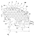
まず、図1を参照すると、軽量化した鏡体支持体用の基板の第1の実施形態の部分切り取り断面図が示されており、全体的に参照符号1が付されている。
First, referring to FIG. 1, a partial cut-away sectional view of a first embodiment of a substrate for a mirror support that has been reduced in weight is shown, and is generally designated by
この実施形態では、基板1は、一部品としての中実材料の一枚の円盤から製造されており、したがって、実質的に丸い円盤の形状をした一体構造(モノリシック構造)である。
In this embodiment, the
本発明の好ましい実施形態では、基板1は、どの時点においても異なる部分に分離されることはなく、別個の処理ステップ中であっても常に一部品のままである。
In a preferred embodiment of the invention, the
図1では底面から示されている基板1は、六角形すなわちハニカム形状のくぼみ部を画定する複数の第1の凹部2、3、4をその裏面に有する。
The
くぼみ部2、3、4とも記載されるこれらの第1の凹部2、3、4間にはつなぎ部材5、6が形成されており、これらのつなぎ部材がくぼみ部2、3、4を互いから分離している。
Connecting
六角形のくぼみ部に加えて、さらに、この実施形態では実質的に円形の断面を有する第2の凹部7、8が基板1の裏面に導入されており、第2の凹部7、8は、くぼみ部7、8とも記載することができ、提供される保持装置を取り込むように設けられている。基板1によって画定される鏡体支持体は、後述の使用のためにこの保持装置に導入される。
In addition to the hexagonal recess, in this embodiment, a
第2の凹部7、8は、特に円筒形の鞘のような形状である構造を本質的に有する部材9、10、すなわちつなぎ部材9、10によって囲まれており、これらの部材はおよそ3mm〜6mmの幅dst1を有する。また、円筒形の鞘形状を有するこれらの部材から本質的に星形に突出するつなぎ部材はおよそ3mm〜6mmの幅を有する。少なくとも円筒形の鞘形状の部材から第1のくぼみ形状凹部の端部まで星形に突出するつなぎ部材は、およそ3mm〜6mmの幅を有する。
The second recesses 7, 8 are surrounded by
この幅の寸法と対比して、ハニカム形状のくぼみ部2、3及び4間に画定されるつなぎ部材5及び6は、2.5mm以下、好ましくは2mm以下の幅tHSを有する。これらの寸法は、(横)部材の高さhsがおよそ90mmであり、基板の全直径がおよそ700mmである基板に利用されるのが有利である。
In contrast to the width dimension, the linking
したがって、本発明による鏡体支持体用の基板1において、異なる幅を有するつなぎ部材を使用する。すなわち、ハニカム形状のくぼみ部2、3、4を画定するつなぎ部材の第1の部分は、円筒形の凹部7、8を画定する部材9、10の幅とは異なる幅を有する。
Therefore, in the
このように、中実材料と比較して重量をかなり低減する場合でも強度要件を満たすことができるが、これらの要件は、基板1にわたって幅が一定であるつなぎ部材を使用することによっては満たすことができない。
In this way, strength requirements can be met even if the weight is significantly reduced compared to solid materials, but these requirements can be met by using a tether that has a constant width across the
直径がおよそ700mmであり、高さhdiskが本質的に90mm〜120mmであり、残りの鏡体支持板の厚さhbottomがおよそ4mm〜6mm、好ましくは5mmである場合、中実材料の円盤と比較して、全体的に重量を85%超低減することが可能である。 If the diameter is approximately 700 mm, the height h disk is essentially 90 mm to 120 mm, and the remaining mirror support plate thickness h bottom is approximately 4 mm to 6 mm, preferably 5 mm, a solid material disk It is possible to reduce the overall weight by more than 85% compared to
個々の場合に、例えば1200mmであるより大きい直径の場合、中実材料と比較して、88パーセント超、最大88.5パーセントまで重量を低減することができた。減量の定義に関しては、本明細書の導入部を参照されたい。 In individual cases, for larger diameters, for example 1200 mm, the weight could be reduced by more than 88 percent and up to 88.5 percent compared to solid materials. See the introductory part of this specification for the definition of weight loss.
さらに、本発明の範囲内で、つなぎ部材の長さ範囲に沿って変化する幅を有するつなぎ部材も提供することができる。 Further, a tie member having a width that varies along the length range of the tie member can be provided within the scope of the present invention.
好ましくは、円筒形の鞘のような形状の部材9、10から星形に突出するこれらのつなぎ部材は、それらの長さ範囲に沿って変化する幅を有するため、このようにしてそれぞれの局所的な安定性の要件により良く適合する。
Preferably, these tethers protruding in a star shape from the cylindrical sheath-
例えば、円筒形の鞘のような形状の部材9、10は、隣接する六角形のくぼみ部のつなぎ部材と合流する接点にかけて広くなるように設計することができ、これらの六角形のくぼみ部のつなぎ部材もこれらの接点の領域において広くすることができ、それによって、例えばこのように基板1に保持力をより良く導入することができる。
For example, the cylindrical sheath-
形状が図1に示す形状と本質的に対応する別の実施形態では、基板の直径φsはおよそ1200mmになり、つなぎ部材4、6及び部材9、10並びに他の(横)部材の高さhsはおよそ140mm〜150mmになる。また、この実施形態では、ハニカム形状のくぼみ部のそれぞれのつなぎ部材の幅は、2.5mm以下、好ましくは2mm以下であり、円筒形の鞘のような形状の部材9、10及びこれらから星形に突出するつなぎ部材の幅はおよそ3mm〜5mmになった。
In another embodiment, the shape essentially corresponds to the shape shown in FIG. 1, the substrate diameter φs is approximately 1200 mm, and the heights h of the connecting
第1の凹部の多くのものでハニカム形状にされたそれぞれのくぼみ部は、70mm〜120mm、好ましくは80mm〜110mm、最も好ましくはおよそ95mmの対辺距離すなわちスパン幅SWを有する。 Each indentation that is honeycomb shaped with many of the first recesses has an opposite side distance or span width SW of 70 mm to 120 mm, preferably 80 mm to 110 mm, and most preferably approximately 95 mm.
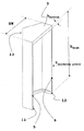
スパン幅の定義をより良く理解するために、図3を参照すると、図1に示される基板1の個々の六角形のくぼみ部(参照符号3)を側部から斜めに見た、部分切り取り断面図が示されている。
For better understanding of the definition of span width, referring to FIG. 3, a partially cut-away cross section of the individual hexagonal depression (reference numeral 3) of the
つなぎ部材5、6のそれ自体の相補部分が各ハニカム形状のくぼみ部2、3及び4に割り当てられているので、結果として、つなぎ部材5、6の幅の半分のみが各個々のくぼみ形状凹部、すなわち互いに隣接して配置されるハニカム2、3及び4に割り当てられており、したがって、それぞれが対になってつなぎ部材5及び6の全幅を画定する。
As a result, only half of the width of the connecting
したがって、スパン幅SWの寸法の定義において、いずれの場合にも、つなぎ部材5、6の幅の半分のみが、基本的に、個々のハニカム形状のくぼみ部3に使用される。
Therefore, in the definition of the dimension of the span width SW, in any case, only half of the width of the connecting
くぼみ部3の開いている裏面端部に配置される隆起した裏面部材11、12も図3において見ることができ、これらの隆起した裏面部材は、ハニカム形状のくぼみ部2、3及び4が互いに隣接して(対で)配置されると本質的にT字形の断面を有し、したがって、基板1から完成した鏡体支持体の安定性にかなり寄与する。
Also seen in FIG. 3 are the raised back
図3からは、鏡体の反射面として設けられている表面13の裏側の材料厚さ、したがって鏡体支持板の厚さすなわち鏡体板の厚さ(hbottom)が、少なくともつなぎ部材5及び6間の領域において実質的に一定であることも非常に良く分かる。
From FIG. 3, the material thickness on the back side of the
しかし、代替的な構成では、つなぎ部材間の鏡体支持板13のこの領域は、放物面となる厚さを辿る、すなわち各つなぎ部材に向かって厚くなってもよく、それによって、各つなぎ部材にさらにより良く力を導入することができる。
However, in an alternative configuration, this region of the
外縁14は、円筒形の鞘の形状で本質的に閉じて設計され、円形のつなぎ部材15によって形成される。
The
縁14を画定する円形のつなぎ部材15の幅は、直径φsがおよそ700mmである第1の実施形態ではおよそ3mm〜8mmになり、この場合、この縁の高さhsはおよそ70mm〜120mmである。
The width of the
鏡体板の厚さ(hbottom)と合わせたこの縁の高さhsは、円盤形状の一部品の鏡体支持体が、平坦又は凹状又は部分的に凹状である鏡体支持板13を有する限り、この支持体の厚さhdiskである。
The height h s of this edge combined with the thickness (h bottom ) of the mirror plate is such that the one-piece mirror support has a flat, concave or partially concave
直径φsがおよそ1200mmであるこの実施形態のより大きいバージョンでは、円形の縁15の高さはおよそ120mm〜180mmになり、縁14を画定するこの部材の幅はまた、およそ3mm〜8mmになる。
In a larger version of this embodiment where the diameter φ s is approximately 1200 mm, the height of the
円盤形状鏡体支持体1の厚さhdiskと基板1の直径φsとの比は、1:3〜1:10の範囲、好ましくは1:5〜1:8の範囲にある。最も好ましくは、基板の厚さhdiskと直径φsとの比は、±15%までのずれを伴っておよそ1:6の範囲にあり、基板1がその自重下で驚くほど高い剛性値を有する、すなわちたるみが極めて小さい。
The ratio of the thickness h disk of the disk-shaped
しかし、図1に示す鏡体支持体が、円形の断面を有する凹部7、8と係合する、鏡体支持体用に提供される保持装置(図示せず)で担持される場合、基板には、その自重により最大およそ1μm〜3μmのみのたるみが生じる。
However, when the mirror support shown in FIG. 1 is carried by a holding device (not shown) provided for the mirror support that engages the
第2の凹部7、8は、縁14から基板半径のおよそ1/3の距離に、また基板の中心点Msから半径の2/3の距離に配置される。
The second recesses 7, 8 are arranged at a distance of approximately 1/3 of the substrate radius from the
上述し、また後述する非円筒形の円盤形状又は柱状基板の場合、基板表面の質量中心から平均縁距離までの距離は、半径と見なされる。この場合、平均縁距離は、対称である中心軸線に対して垂直に延びる完全な円にわたって平均化することによって全ての縁距離の平均値となる。 In the case of the non-cylindrical disk shape or columnar substrate described above and described later, the distance from the center of mass of the substrate surface to the average edge distance is regarded as a radius. In this case, the average edge distance is the average of all edge distances by averaging over a complete circle extending perpendicular to the symmetrical central axis.
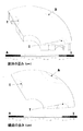
基板1のその自重によるたるみを、本質的に形状が同様に変化する表面の形態で図2に概略的に示す。
The sagging due to its own weight of the
図2の一方は、図1に示す基板1においてその自重により生じるたるみを示す、その上面を上方から斜めに見下ろした図である。この図は、自重による鏡体本体のたるみを示す。
One of FIGS. 2A and 2B shows a sag caused by its own weight in the
図2の下方には、鏡体支持板13の上面図が示されており、この図から、表面の等しいたるみがこの鏡面にわたってどのように本質的に対称的に分散するかを理解することができる。この図は鏡面のたるみを示す。
In the lower part of FIG. 2, a top view of the
図2に示すたるみすなわち歪みは、いわゆる「等値線プロット」によって示される。各線は、1つの一定のたるみ値を示す。例えば、図2の上方の目盛りは約−1.35μm(大文字「A」によって示される)から約−0.02μm(大文字「P」によって示される)の範囲である。より良く理解するために、等値線「B」及び「O」を上方の図に示す。後述の図4、図6及び図7にも同じ表現方法を選択する。 The sagging or distortion shown in FIG. 2 is indicated by a so-called “isoline plot”. Each line represents one constant sag value. For example, the upper scale in FIG. 2 ranges from about −1.35 μm (indicated by capital letter “A”) to about −0.02 μm (indicated by capital letter “P”). For better understanding, isolines “B” and “O” are shown in the upper diagram. The same expression method is also selected in FIGS. 4, 6 and 7 described later.
たるみの対称性は、図4の個々のくぼみ部3に関しても良好に認識することができ、図4は、図3において側部から斜めに見た部分切り取り断面図で示す個々のくぼみ部3の領域における鏡体板のたるみを示す。
The symmetry of the slack can be recognized well with respect to the
鏡体板13の固有の重量による本質的にハニカム形状のくぼみ部3の中心のたるみの最大値は、およそ12nmに過ぎないという驚くほど小さい最大値になる。
The maximum value of the center sag of the hollow honeycomb-shaped
このように、鏡体板13の後の処理、例えば研削及び研磨も極めて高精密に行うことができ、これは、後の鏡体の理論的形状からのずれが非常にわずかであることを意味する。
In this way, the subsequent processing of the
この処理の精密性は、基板1の裏面16が実質的に平坦であるように設計されていることによりさらに高まり、それによって、基板1が処理の際に実質的に平坦な下敷上に配置されたときに、基板1は、最小限の歪みしか受けない。
The precision of this process is further enhanced by the fact that the
別の構成では、基板1は、本明細書において示される全ての実施形態において開口17を有してもよく、この開口17は(基板の)ほぼ中心に配置されるのが好ましく、この場合、内縁18によって画定されるのが好ましい。
In another configuration, the
さらに好ましい構成では、この内縁18は、実質的に円筒形状の鞘の形に形成された円形の閉じた部材19によって形成され、後の鏡体の光学的構成に応じて、その幅はおよそ3mm〜8mmになり、その高さはおよそ10mm〜50mm、好ましくは20mm〜40mm、最も好ましくはおよそ30mmになる。
In a further preferred configuration, this
そのような開口17がない実施形態、すなわち、基板1の表面13すなわち鏡体支持板13の表面全体にわたって閉じている実施形態も、本発明の範囲内にある。そのような実施形態では、部材19を省くのが好ましく、開口17が本来あるであろう基板1の中心領域にもハニカム形状のくぼみ部を配置する。
Embodiments that do not have
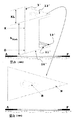
以下では図5を参照する。図5は、軽量化し、くぼみ部を画定する三角形の凹部2’、3’及び4’が設けられた鏡体支持体用の基板1’の本発明による第2の実施形態を、底面側から斜めに見下ろした部分切り取り断面図を示す。
In the following, reference is made to FIG. FIG. 5 shows, from the bottom side, a second embodiment according to the invention of a
本発明によるこの第2の実施形態では、図1〜図4に示す本発明による第1の実施形態と同じ参照番号が付されており、以下の説明では、本発明による第2の実施形態の参照番号に、さらに1つの引用符を追加して述べる。本発明による第1の実施形態に関して前もって与えられている全ての情報は、以下で別途明記しない限り第2の実施形態及びそのそれぞれの構成要素にも適用可能である。 In this second embodiment according to the present invention, the same reference numerals as in the first embodiment according to the present invention shown in FIGS. 1 to 4 are given, and in the following description, the second embodiment according to the present invention is described. Add one more quotation mark to the reference number. All information given in advance with respect to the first embodiment according to the invention is also applicable to the second embodiment and its respective components unless otherwise specified below.
また、本発明による第2の実施形態では、円盤形状基板1’の700mm又は1200mmという2つの直径φsを使用するのが好ましい。 In the second embodiment according to the present invention, it is preferred to use two diameters phi s of 700mm or 1200mm disk-shaped substrate 1 '.
第2の実施形態では、スパン幅SWを有する六角形ハニカム形状の第1の凹部2、3及び4の代わりに、三角形のくぼみ部2’、3’及び4’を、縁の長さKLによりそれらの寸法を画定し、この場合、図7にも示すように、くぼみ形状凹部によって画定されるそれぞれのつなぎ部材5’及び6’の幅の半分のみを基準として使用する。
In the second embodiment, instead of the hexagonal honeycomb-shaped first recesses 2, 3 and 4 having the span width SW,
三角形のくぼみ部を有するこの第2の実施形態では、辺の長さKLはおよそ70mm〜210mm、好ましくは120mm〜180mm、最も好ましくはおよそ140mmになる。 In this second embodiment with triangular indentations, the side length KL is approximately 70 mm to 210 mm, preferably 120 mm to 180 mm, most preferably approximately 140 mm.
基板1’の裏面16’にある隆起した裏面部材11’及び12’を図7ではよく認識することができ、これは、例えばくぼみ部3’及び4’の場合のように互いに隣接する三角形のくぼみ部に関して本質的にT字形の接続断面を基板1’に画定する。
The raised back
また、本発明によるこれらの実施形態の三角形くぼみ部の場合にも、それらの自重下で驚くほど小さいたるみ値しか生じなかった。 Also, in the case of the triangular indentations of these embodiments according to the present invention, only surprisingly small sag values occurred under their own weight.
たるみを判断するために、この実施形態も、ハニカム形状のくぼみ部を有する第1の実施形態に関して既に説明したような方法で判断した。 In order to determine the sagging, this embodiment was also determined by the method already described with respect to the first embodiment having a honeycomb-shaped recess.
図6は、図5に示す基板1’が3つの保持装置によって持ち上げられている場合、基板1’において生じるたるみを示し、この場合、3つの保持装置は、半径のおよそ2/3のところで基板1’と接触しているおり、一方の図はその上面から斜めに見下ろした部分切り取り断面図を示す。この図は、鏡体本体のその自重によるたるみを示す。
FIG. 6 shows the slack that occurs in the
基板1’の上面13’を上から見た図も図6の下側に示す。この図は、鏡面のたるみを示す。 A view of the upper surface 13 'of the substrate 1' as viewed from above is also shown on the lower side of FIG. This figure shows the sagging of the mirror surface.
また、この第2の実施形態では、最大たるみはわずか0.5μm〜3μmにしかならず、この鏡体支持体1’は極めて機械的に安定であることも示された。
In the second embodiment, the maximum sag is only 0.5 μm to 3 μm, and it has been shown that the
また、図7に示す個々のくぼみ部3’の場合、鏡体支持板13’のその自重によるたるみは最大でもおよそ12nmしか生じず、それによって、既に前述した利点を全て達成することができる。 Further, in the case of the individual indentations 3 'shown in FIG. 7, the slack due to the weight of the mirror support plate 13' is only about 12 nm at the maximum, whereby all the advantages already described above can be achieved.
この第2の実施形態では、前述した基板1’の厚さと直径との有利な比も実現することができる。 In this second embodiment, the advantageous ratio between the thickness and the diameter of the substrate 1 'described above can also be realized.
くぼみ形状凹部2、2’、3、3’、4及び4’の製造を説明するために図8を参照するが、この図8は、軽量化した基板1、1’の製造における処理ステップを説明するのに役立つ。
Reference is made to FIG. 8 to illustrate the manufacture of the recessed
凹部、特に第1の凹部2、2’、3、3’及び4、4’をまず、一部品の、したがって一体構造の円形本体の基板1、1’に、好ましくは図8のいくつかの位置に示されている回転工具20を使用することによってその裏面16、16’から導入する。基板1、1’は、好ましくは円盤形状又は柱状の基本形状であるが、柱状又は円盤形状の寸法に加えて、楕円形、矩形、六角形又は八角形の本体であってもよい。
The recesses, in particular the
回転工具20は、円筒形の鞘のような形状であるその外側並びにその前面22及び裏面23の両方に材料を除去するのに好適である砥粒構造物を担持したヘッド21を含む。
The
一方で、これらの砥粒構造物は、固定砥粒が設けられた砥石車からなる。 On the other hand, these abrasive grain structures are composed of a grinding wheel provided with fixed abrasive grains.
さらに、より細かく表面処理するために、遊離砥粒でラップ仕上げすることも含み得る。 Further, it may include lapping with loose abrasive for finer surface treatment.
くぼみ部2、2’、3、3’及び4、4’並びにこれらの間に配置されるつなぎ部材5、5’及び6、6’をそれぞれこのように本質的にそれらの基本形状から準備した後、これらのくぼみ部の表面から材料をさらに除去するためにエッチング剤でさらに処理することができる。
The
このエッチング剤は、特に、基板1、1’がガラス又はガラスセラミックである場合にフッ化水素酸を含むのも好ましい。
This etchant also preferably contains hydrofluoric acid, especially when the
特に好ましくは、エッチング剤は、10体積%超のフッ化水素酸を含む。 Particularly preferably, the etching agent comprises more than 10% by volume of hydrofluoric acid.
本質的にそのようなエッチング剤を用いて材料を除去する機械的処理であるこの手順に続いて、強度を高めるために、研削又はラップ仕上げにおいて用いられる研磨材によって、くぼみ部の各表面から、その最大直径にわたって少なくとも再度材料を除去することができる。 Following this procedure, which is essentially a mechanical process that removes material using such an etchant, from each surface of the indentation by an abrasive used in grinding or lapping to increase strength, Material can be removed at least again over its maximum diameter.
つなぎ部材の幅を減らすために、表面の材料のこのさらなる除去は0.5mm〜4mmにもなり得る。好ましくは、全てのガラス及びガラスセラミック(特に好ましい)を基板1、1’の材料として使用することができる。
In order to reduce the width of the tether, this further removal of surface material can be as much as 0.5 mm to 4 mm. Preferably, all glasses and glass ceramics (particularly preferred) can be used as the material for the
例えば、摂氏0度〜50度の範囲の温度における熱膨張係数が1ケルビン当たり4×10⁻⁶未満であるホウケイ酸ガラスをガラスとして使用することができる。 For example, a borosilicate glass having a thermal expansion coefficient of less than 4 × 10 −6 per Kelvin at a temperature in the range of 0 to 50 degrees Celsius can be used as the glass.
使用するのに特に好ましいのは、摂氏0度〜50度の範囲における熱膨張係数が1×10⁻⁶未満、通常は1ケルビン当たり0.5×10⁻⁶である石英ガラス(溶融石英)である。 Particularly preferred for use is quartz glass (fused quartz) with a coefficient of thermal expansion in the range of 0 to 50 degrees Celsius of less than 1 × 10 −6 , usually 0.5 × 10 −6 per Kelvin. is there.
これらのタイプのガラスは、超低膨張ガラスすなわちULEガラスとも称され、例えば米国特許第5,970,751号明細書に記載されている、例えばTiO2をドープした熱膨張係数が低い石英ガラス等のドープ石英ガラスも含み得る。 These types of glass are also referred to as ultra-low expansion glass or ULE glass, and are described in, for example, US Pat. No. 5,970,751, such as quartz glass having a low thermal expansion coefficient doped with TiO 2. May also be included.
しかし、摂氏0度〜50度の温度範囲における熱膨張係数が通常は1ケルビン当たり0.1×10⁻⁶未満であるガラスセラミックを使用するのが最も好ましい。 However, it is most preferred to use a glass ceramic whose coefficient of thermal expansion in the temperature range of 0 to 50 degrees Celsius is usually less than 0.1 × 10 −6 per Kelvin.
特に好ましいガラスセラミックは、例えば、独国特許出願公開第1902432号明細書、米国特許第4,851,372号明細書又は独国特許出願公開第102004008824号明細書に記載されているような、例えばショット アクチエンゲゼルシャフト (マインツ)のZERODUR(登録商標)等のLi−Al−Siガラスセラミックを含む。 Particularly preferred glass ceramics are, for example, those described in German Offenlegungsschrift 1902432, U.S. Pat. No. 4,851,372 or German Offenlegungsschrift 102004008824. It includes Li-Al-Si glass ceramics such as ZERODUR (registered trademark) of Schott Aktiengesellschaft.
別の好ましいガラスセラミックのファミリーは、例えば米国特許第5,591,682号明細書に記載されている、クリアセラム(登録商標)の名称で株式会社オハラ(日本)から市販されているものを含む。 Another preferred family of glass ceramics includes those commercially available from OHARA INC. (Japan) under the name Clear Serum®, for example as described in US Pat. No. 5,591,682. .
反射層を、鏡体支持体1、1’の表面13、13’の少なくとも一部に、好ましくはこの表面全体にわたって導入することができ、特に表面13、13’に研磨等の適切な処理ステップを繰り返し施した後でこのように製造することができる。
A reflective layer can be introduced on at least a part of the
この反射層は、蒸着又は任意の他の好適な塗布プロセスによって導入される金属層を含んでいてもよく、続いてこの層に、好ましくは金属酸化物誘電体層であるさらに別の層を被覆して保護することができる。 This reflective layer may comprise a metal layer introduced by vapor deposition or any other suitable application process, followed by coating this layer with another layer, preferably a metal oxide dielectric layer. And can be protected.
金属反射層とは代替的に、又はこれに加えて、誘電反射層又はさらには誘電反射多層系を導入することができる。 As an alternative to or in addition to the metallic reflective layer, a dielectric reflective layer or even a dielectric reflective multilayer system can be introduced.
それぞれの場合に目的とする光学的使用及び用途に応じて、この反射面の一部を平坦に形成するか、又は平坦ではなく、特に球形若しくは非球形に形成することができる。 Depending on the intended optical use and application in each case, a part of this reflecting surface can be formed flat, or not flat, in particular spherical or non-spherical.
このように、凸状、凹状並びに部分的に凸状及び/又は部分的に凹状である表面の幾何学的形状を作り出すことができる。しかし、表面13、13’の形状は、基板1、1’の裏面に凹部を導入した後で、一体構造である基板1、1’の本体から加工されるのが好ましい。
In this way, convex, concave and partially convex and / or partially concave surface geometries can be created. However, the shapes of the
球形及び非球形の形状に加えて、例えば光学的な計算から作り出すことができる自由に形成した表面も本発明の範囲内で使用することができる。 In addition to spherical and non-spherical shapes, freely formed surfaces that can be created, for example, from optical calculations can also be used within the scope of the present invention.
鏡体に衝突するそれぞれの電磁波の位相面の光膨張にさらに影響を与えるために、反射面13、13’は、例えば収差を補正するために使用することができる回折表面構造をさらに含み得る。
In order to further influence the optical expansion of the phase plane of each electromagnetic wave impinging on the mirror body, the reflecting
このために、この回折構造は、格子構造及び/又はホログラフィック構造、特に画定位相面膨張構造を含み得る。 For this purpose, the diffractive structure may comprise a grating structure and / or a holographic structure, in particular a delimited phase plane expansion structure.
凹面鏡又は凸面鏡の形状である場合に、基板1、1’の膨らみを小さくするために、表面13、13’の複数の部分はフレネル構造も含み得る。これは当業者に既知であるため図示しない。
In order to reduce the bulge of the
回折構造及びフレネル構造を同じ基板1、1’上で組み合わせて使用してもよく、本発明の範囲内にある。
A diffractive structure and a Fresnel structure may be used in combination on the
本発明は、別々に説明した上記実施形態に限定されず、それぞれ説明した他の実施形態の特徴を有する実施形態も含み、そのため、上記実施形態の例は特徴を限定するためのものではなく、例示に過ぎない。 The present invention is not limited to the above-described embodiments described separately, but also includes embodiments having the characteristics of the other embodiments described above. Therefore, the examples of the embodiments are not intended to limit the characteristics. It is only an example.
Claims (22)
前記第1の凹部を画定する前記つなぎ部材の少なくとも第1の部分は、前記第2の凹部を画定する前記つなぎ部材の第2の部分とは異なる幅を有することを特徴とする基板。 A substrate for a mirror support that has been reduced in weight, wherein the first recess and the second recess are introduced into the surface of the substrate, and as a result, between the first recess and the first recess, And a bridging member is defined between the first recess and the second recess, the second recess defining an intake for the holding device;
At least a first portion of the linking member defining the first recess has a different width than a second portion of the linking member defining the second recess.
Applications Claiming Priority (2)
| Application Number | Priority Date | Filing Date | Title |
|---|---|---|---|
| DE102008039042.9 | 2008-08-21 | ||
| DE102008039042A DE102008039042B4 (en) | 2008-08-21 | 2008-08-21 | Substrate for a mirror carrier with reduced weight and mirror with weight-reduced mirror carrier |
Publications (2)
| Publication Number | Publication Date |
|---|---|
| JP2010049257A true JP2010049257A (en) | 2010-03-04 |
| JP5244050B2 JP5244050B2 (en) | 2013-07-24 |
Family
ID=41605637
Family Applications (1)
| Application Number | Title | Priority Date | Filing Date |
|---|---|---|---|
| JP2009191982A Active JP5244050B2 (en) | 2008-08-21 | 2009-08-21 | A substrate for a light-weight mirror support and a mirror provided with a light-weight mirror support |
Country Status (4)
| Country | Link |
|---|---|
| US (2) | US8911098B2 (en) |
| JP (1) | JP5244050B2 (en) |
| DE (1) | DE102008039042B4 (en) |
| FR (1) | FR2935178B1 (en) |
Cited By (5)
| Publication number | Priority date | Publication date | Assignee | Title |
|---|---|---|---|---|
| EP2367390A1 (en) | 2010-03-05 | 2011-09-21 | Fujitsu Limited | Radio communication system, radio communication method, gateway apparatus, and radio station |
| JP2012162449A (en) * | 2011-01-19 | 2012-08-30 | Schott Ag | Substrate having lightweight structure |
| JP2012230149A (en) * | 2011-04-25 | 2012-11-22 | Mitsubishi Electric Corp | Lightweight mirror |
| JP2016531328A (en) * | 2013-09-13 | 2016-10-06 | レイセオン カンパニー | Optimal kinematic mount for large mirrors |
| JP2017024415A (en) * | 2015-07-23 | 2017-02-02 | ショット アクチエンゲゼルシャフトSchott AG | Monolithic support for full-surface support of workpiece |
Families Citing this family (11)
| Publication number | Priority date | Publication date | Assignee | Title |
|---|---|---|---|---|
| DE102008039042B4 (en) * | 2008-08-21 | 2011-04-14 | Schott Ag | Substrate for a mirror carrier with reduced weight and mirror with weight-reduced mirror carrier |
| DE102009005400B4 (en) * | 2009-01-19 | 2011-04-07 | Schott Ag | Substrate for a mirror support, made of glass or glass ceramic |
| DE102011051198B4 (en) * | 2011-06-20 | 2016-11-10 | Scanlab Ag | Method for producing a weight-optimized deflection mirror |
| US20130027795A1 (en) * | 2011-07-29 | 2013-01-31 | Gsi Group Corporation | Systems and methods for providing mirrors with high stiffness and low inertia involving chemical etching |
| DE102013106612A1 (en) | 2013-06-25 | 2015-01-08 | Schott Ag | Tool crown and with the tool crown manufacturable glass ceramic product |
| CN106019529B (en) * | 2016-06-23 | 2018-11-02 | 中国科学院长春光学精密机械与物理研究所 | A kind of space aluminium base mirror assembly |
| CN107797169B (en) * | 2017-11-16 | 2019-01-11 | 中国科学院长春光学精密机械与物理研究所 | Off axis reflector mirror and its processing method |
| US10877237B2 (en) | 2017-11-30 | 2020-12-29 | Raytheon Company | Multi-material mirror system |
| US11327208B2 (en) * | 2018-05-30 | 2022-05-10 | Raytheon Company | Method of manufacture for a lightweight, high-precision silicon carbide mirror assembly |
| US11726240B2 (en) * | 2020-02-14 | 2023-08-15 | Google Llc | Variable mesh low mass MEMS mirrors |
| CN113504626B (en) * | 2021-06-21 | 2023-04-11 | 上海现代先进超精密制造中心有限公司 | 3D prints optical reflector |
Citations (4)
| Publication number | Priority date | Publication date | Assignee | Title |
|---|---|---|---|---|
| JPS503655B1 (en) * | 1969-10-18 | 1975-02-07 | ||
| JPH052102U (en) * | 1991-06-26 | 1993-01-14 | 日本石英硝子株式会社 | Double-sided quartz glass lightweight mirror |
| JP2003185811A (en) * | 2001-12-14 | 2003-07-03 | Mitsubishi Electric Corp | Lightweight mirror |
| JP2005234344A (en) * | 2004-02-20 | 2005-09-02 | Taiheiyo Cement Corp | Mirror for astronomical telescope |
Family Cites Families (27)
| Publication number | Priority date | Publication date | Assignee | Title |
|---|---|---|---|---|
| US3514275A (en) * | 1965-10-18 | 1970-05-26 | Owens Illinois Inc | Lightweight telescope mirror blank product and process of producing the same from glass |
| DE1299131B (en) * | 1966-08-20 | 1969-07-10 | Zeiss Carl Fa | Optical mirror, especially for astronomical devices, in lightweight construction |
| DE1902432B2 (en) | 1967-07-01 | 1976-10-14 | Jenaer Glaswerk Schott & Gen., 6500 Mainz | TRANSPARENT GLASS CERAMICS WITH A THERMAL EXPANSION COEFFICIENT OF 0 + 1.5 TIMES 10 HIGH -7 / DEGREE C WHICH IS LITTLE TEMPERATURE DEPENDENT IN THE RANGE FROM -30 TO + 70 DEGREES C. |
| US3490405A (en) * | 1967-08-23 | 1970-01-20 | Nasa | Method and apparatus for making curved reflectors |
| US3600257A (en) * | 1969-01-09 | 1971-08-17 | Westinghouse Electric Corp | Lightweight mirror structures |
| US3754812A (en) * | 1971-03-04 | 1973-08-28 | Heraeus Schott Quarzschmelze | Lightweight optical elements with honeycomb support plate |
| JPS5838083B2 (en) * | 1980-01-22 | 1983-08-20 | 株式会社日本自動車部品総合研究所 | Die equipment for extrusion molding of honeycomb structures |
| DE3018785C2 (en) * | 1980-05-16 | 1982-04-15 | Heraeus Quarzschmelze Gmbh, 6450 Hanau | Lightweight mirrors, especially for astronomical purposes and processes for their manufacture |
| GB2159514B (en) | 1984-05-23 | 1987-12-02 | Zeiss Stiftung | Glass ceramic with specific thermal expansion behaviour |
| FR2609179B1 (en) | 1986-12-30 | 1989-08-18 | Sfim | PROCESS FOR REALIZING A REFLECTIVE FACE ON AN ALVEOLAR STRUCTURE IN ORDER TO OBTAIN AN ULTRA-LIGHT MIRROR |
| US4902216A (en) * | 1987-09-08 | 1990-02-20 | Corning Incorporated | Extrusion die for protrusion and/or high cell density ceramic honeycomb structures |
| KR920703324A (en) * | 1989-08-15 | 1992-12-17 | 원본미기재 | Film-Based Composite Structure for Ultralight SDI System |
| US5076700A (en) * | 1990-12-20 | 1991-12-31 | Litton Systems, Inc. | Bonded lightweight mirror structure |
| JP3031571B2 (en) | 1991-06-25 | 2000-04-10 | 触媒化成工業株式会社 | Hard coat film and substrate with hard coat film |
| JPH0815380B2 (en) | 1991-09-25 | 1996-02-14 | 三菱電機株式会社 | Method for manufacturing control device for charging generator |
| DE4220472C2 (en) * | 1992-03-05 | 2002-08-22 | Industrieanlagen Betriebsges | Process for the production of lightweight reflectors using silicon wafers |
| US5565052A (en) * | 1992-03-05 | 1996-10-15 | Industrieanlagen-Betriebsgesellschaft Gmbh | Method for the production of a reflector |
| JP2668057B2 (en) | 1994-09-13 | 1997-10-27 | 株式会社オハラ | Low expansion transparent glass ceramics |
| DE19840004A1 (en) * | 1998-09-02 | 2000-03-09 | Mekra Lang Gmbh & Co Kg | Outside mirrors for motor vehicles |
| US5970751A (en) | 1998-09-22 | 1999-10-26 | Corning Incorporated | Fused SiO2 -TiO2 glass method |
| EP1415779B1 (en) * | 2001-07-13 | 2009-09-23 | Ngk Insulators, Ltd. | Honeycomb structural body, honeycomb filter, and method of manufacturing the structural body and the filter |
| EP1316686B1 (en) * | 2001-12-03 | 2007-09-05 | Hitachi Metals, Ltd. | Ceramic honeycomb filter |
| FR2857660B1 (en) * | 2003-07-18 | 2006-03-03 | Snecma Propulsion Solide | THERMOSTRUCTURAL COMPOSITE STRUCTURE HAVING A COMPOSITION GRADIENT AND METHOD OF MANUFACTURING THE SAME |
| DE102004008824B4 (en) | 2004-02-20 | 2006-05-04 | Schott Ag | Glass ceramic with low thermal expansion and their use |
| FR2904433B1 (en) * | 2006-07-25 | 2008-11-28 | Alcatel Sa | DEVICE FOR FASTENING A VITROCERAMIC OR CERAMIC MIRROR ON A STRUCTURE ON BOARD A SPATIAL ENGINE OPERATING AT CRYOGENIC TEMPERATURE |
| WO2008126306A1 (en) * | 2007-03-30 | 2008-10-23 | Ibiden Co., Ltd. | Catalyst support |
| DE102008039042B4 (en) * | 2008-08-21 | 2011-04-14 | Schott Ag | Substrate for a mirror carrier with reduced weight and mirror with weight-reduced mirror carrier |
-
2008
- 2008-08-21 DE DE102008039042A patent/DE102008039042B4/en active Active
-
2009
- 2009-08-20 US US12/583,400 patent/US8911098B2/en active Active
- 2009-08-21 FR FR0904022A patent/FR2935178B1/en active Active
- 2009-08-21 JP JP2009191982A patent/JP5244050B2/en active Active
-
2014
- 2014-10-30 US US14/527,995 patent/US20150053836A1/en not_active Abandoned
Patent Citations (4)
| Publication number | Priority date | Publication date | Assignee | Title |
|---|---|---|---|---|
| JPS503655B1 (en) * | 1969-10-18 | 1975-02-07 | ||
| JPH052102U (en) * | 1991-06-26 | 1993-01-14 | 日本石英硝子株式会社 | Double-sided quartz glass lightweight mirror |
| JP2003185811A (en) * | 2001-12-14 | 2003-07-03 | Mitsubishi Electric Corp | Lightweight mirror |
| JP2005234344A (en) * | 2004-02-20 | 2005-09-02 | Taiheiyo Cement Corp | Mirror for astronomical telescope |
Cited By (6)
| Publication number | Priority date | Publication date | Assignee | Title |
|---|---|---|---|---|
| EP2367390A1 (en) | 2010-03-05 | 2011-09-21 | Fujitsu Limited | Radio communication system, radio communication method, gateway apparatus, and radio station |
| JP2012162449A (en) * | 2011-01-19 | 2012-08-30 | Schott Ag | Substrate having lightweight structure |
| JP2012230149A (en) * | 2011-04-25 | 2012-11-22 | Mitsubishi Electric Corp | Lightweight mirror |
| JP2016531328A (en) * | 2013-09-13 | 2016-10-06 | レイセオン カンパニー | Optimal kinematic mount for large mirrors |
| US9958638B2 (en) | 2013-09-13 | 2018-05-01 | Raytheon Company | Optimal kinematic mount for large mirrors |
| JP2017024415A (en) * | 2015-07-23 | 2017-02-02 | ショット アクチエンゲゼルシャフトSchott AG | Monolithic support for full-surface support of workpiece |
Also Published As
| Publication number | Publication date |
|---|---|
| FR2935178B1 (en) | 2015-03-13 |
| DE102008039042A1 (en) | 2010-03-04 |
| DE102008039042B4 (en) | 2011-04-14 |
| US8911098B2 (en) | 2014-12-16 |
| US20100103546A1 (en) | 2010-04-29 |
| FR2935178A1 (en) | 2010-02-26 |
| JP5244050B2 (en) | 2013-07-24 |
| US20150053836A1 (en) | 2015-02-26 |
Similar Documents
| Publication | Publication Date | Title |
|---|---|---|
| JP5244050B2 (en) | A substrate for a light-weight mirror support and a mirror provided with a light-weight mirror support | |
| US8864324B2 (en) | Substrate with lightweight structure | |
| EP2154583B1 (en) | Hairspring for sprung balance | |
| CN110998231B (en) | High-quality factor MEMS silicon life fancy vibration gyroscope | |
| EP1519250B1 (en) | Thermally compensated balance-hairspring resonator | |
| EP3759554B1 (en) | Method for manufacturing a hairspring | |
| JP5495809B2 (en) | Mirror support substrate made of glass or glass ceramic | |
| CH702151A1 (en) | Pieces of method for producing micromechanical including glass ceramic. | |
| EP2869138B1 (en) | Hairspring for a regulating member of a mechanical watch, regulating member provided with such a hairspring, and method for manufacturing such a hairspring | |
| EP3982205A1 (en) | Method for manufacturing a timepiece spring with precise stiffness | |
| JP4447694B2 (en) | Optical member support structure | |
| CH700812B1 (en) | Spiral spring for regulator unit of movement of clock or timepiece, has N arms with identical geometries occupying angular space or specific repetition angle around axis of spring and concentrically wound with respect to each other | |
| Hinkle et al. | Cryogenic single-crystal silicon optics | |
| CH714815A2 (en) | Process for manufacturing a silicon spiral for watchmaking | |
| Rozelot et al. | Aluminium mirrors versus glass mirrors | |
| Kaneda et al. | Development of SiC mirror for ASTRO-F | |
| Morrison | Development Problems of the Primary Mirror for Large Space Telescopes | |
| Ruch | Alternative substrates to glass mirrors | |
| KR20230065237A (en) | A method for manufacturing optical elements for optical telescopes usable in space missions | |
| CH709730A2 (en) | A method of manufacturing a composite balance spring. | |
| Geyl | High-power optics at REOSC | |
| Vukobratovich et al. | Optomechanical Engineering Handbook Ed. Anees Ahmad Boca Raton: CRC Press LLC, 1999 | |
| Guo et al. | Design and analysis of lightweight pointing mirror used in space camera | |
| JPH07240359A (en) | X-ray mask, x-ray mask blanks and their manufacture | |
| Schmidt-Kaler | Optical Configurations of Very Large Telescopes |
Legal Events
| Date | Code | Title | Description |
|---|---|---|---|
| A977 | Report on retrieval |
Free format text: JAPANESE INTERMEDIATE CODE: A971007 Effective date: 20110817 |
|
| A131 | Notification of reasons for refusal |
Free format text: JAPANESE INTERMEDIATE CODE: A131 Effective date: 20110905 |
|
| A601 | Written request for extension of time |
Free format text: JAPANESE INTERMEDIATE CODE: A601 Effective date: 20111205 |
|
| A602 | Written permission of extension of time |
Free format text: JAPANESE INTERMEDIATE CODE: A602 Effective date: 20111208 |
|
| A521 | Request for written amendment filed |
Free format text: JAPANESE INTERMEDIATE CODE: A523 Effective date: 20120305 |
|
| RD04 | Notification of resignation of power of attorney |
Free format text: JAPANESE INTERMEDIATE CODE: A7424 Effective date: 20120710 |
|
| A131 | Notification of reasons for refusal |
Free format text: JAPANESE INTERMEDIATE CODE: A131 Effective date: 20121115 |
|
| A521 | Request for written amendment filed |
Free format text: JAPANESE INTERMEDIATE CODE: A523 Effective date: 20130213 |
|
| TRDD | Decision of grant or rejection written | ||
| A01 | Written decision to grant a patent or to grant a registration (utility model) |
Free format text: JAPANESE INTERMEDIATE CODE: A01 Effective date: 20130307 |
|
| A61 | First payment of annual fees (during grant procedure) |
Free format text: JAPANESE INTERMEDIATE CODE: A61 Effective date: 20130405 |
|
| FPAY | Renewal fee payment (event date is renewal date of database) |
Free format text: PAYMENT UNTIL: 20160412 Year of fee payment: 3 |
|
| R150 | Certificate of patent or registration of utility model |
Free format text: JAPANESE INTERMEDIATE CODE: R150 Ref document number: 5244050 Country of ref document: JP Free format text: JAPANESE INTERMEDIATE CODE: R150 |
|
| R250 | Receipt of annual fees |
Free format text: JAPANESE INTERMEDIATE CODE: R250 |
|
| R250 | Receipt of annual fees |
Free format text: JAPANESE INTERMEDIATE CODE: R250 |
|
| R250 | Receipt of annual fees |
Free format text: JAPANESE INTERMEDIATE CODE: R250 |
|
| R250 | Receipt of annual fees |
Free format text: JAPANESE INTERMEDIATE CODE: R250 |
|
| R250 | Receipt of annual fees |
Free format text: JAPANESE INTERMEDIATE CODE: R250 |
|
| R250 | Receipt of annual fees |
Free format text: JAPANESE INTERMEDIATE CODE: R250 |
|
| R250 | Receipt of annual fees |
Free format text: JAPANESE INTERMEDIATE CODE: R250 |
|
| R250 | Receipt of annual fees |
Free format text: JAPANESE INTERMEDIATE CODE: R250 |
|
| R250 | Receipt of annual fees |
Free format text: JAPANESE INTERMEDIATE CODE: R250 |