JP2010048254A - Multi-frequency control stage for improved dampening of excitation factor - Google Patents
Multi-frequency control stage for improved dampening of excitation factor Download PDFInfo
- Publication number
- JP2010048254A JP2010048254A JP2009192760A JP2009192760A JP2010048254A JP 2010048254 A JP2010048254 A JP 2010048254A JP 2009192760 A JP2009192760 A JP 2009192760A JP 2009192760 A JP2009192760 A JP 2009192760A JP 2010048254 A JP2010048254 A JP 2010048254A
- Authority
- JP
- Japan
- Prior art keywords
- control stage
- nozzle chamber
- arc
- turbine
- entry
- Prior art date
- Legal status (The legal status is an assumption and is not a legal conclusion. Google has not performed a legal analysis and makes no representation as to the accuracy of the status listed.)
- Granted
Links
Images


Classifications
-
- F—MECHANICAL ENGINEERING; LIGHTING; HEATING; WEAPONS; BLASTING
- F01—MACHINES OR ENGINES IN GENERAL; ENGINE PLANTS IN GENERAL; STEAM ENGINES
- F01D—NON-POSITIVE DISPLACEMENT MACHINES OR ENGINES, e.g. STEAM TURBINES
- F01D9/00—Stators
- F01D9/02—Nozzles; Nozzle boxes; Stator blades; Guide conduits, e.g. individual nozzles
- F01D9/04—Nozzles; Nozzle boxes; Stator blades; Guide conduits, e.g. individual nozzles forming ring or sector
- F01D9/047—Nozzle boxes
-
- F—MECHANICAL ENGINEERING; LIGHTING; HEATING; WEAPONS; BLASTING
- F01—MACHINES OR ENGINES IN GENERAL; ENGINE PLANTS IN GENERAL; STEAM ENGINES
- F01D—NON-POSITIVE DISPLACEMENT MACHINES OR ENGINES, e.g. STEAM TURBINES
- F01D17/00—Regulating or controlling by varying flow
- F01D17/10—Final actuators
- F01D17/12—Final actuators arranged in stator parts
- F01D17/14—Final actuators arranged in stator parts varying effective cross-sectional area of nozzles or guide conduits
- F01D17/141—Final actuators arranged in stator parts varying effective cross-sectional area of nozzles or guide conduits by means of shiftable members or valves obturating part of the flow path
- F01D17/145—Final actuators arranged in stator parts varying effective cross-sectional area of nozzles or guide conduits by means of shiftable members or valves obturating part of the flow path by means of valves, e.g. for steam turbines
-
- F—MECHANICAL ENGINEERING; LIGHTING; HEATING; WEAPONS; BLASTING
- F01—MACHINES OR ENGINES IN GENERAL; ENGINE PLANTS IN GENERAL; STEAM ENGINES
- F01D—NON-POSITIVE DISPLACEMENT MACHINES OR ENGINES, e.g. STEAM TURBINES
- F01D17/00—Regulating or controlling by varying flow
- F01D17/10—Final actuators
- F01D17/12—Final actuators arranged in stator parts
- F01D17/18—Final actuators arranged in stator parts varying effective number of nozzles or guide conduits, e.g. sequentially operable valves for steam turbines
-
- F—MECHANICAL ENGINEERING; LIGHTING; HEATING; WEAPONS; BLASTING
- F01—MACHINES OR ENGINES IN GENERAL; ENGINE PLANTS IN GENERAL; STEAM ENGINES
- F01D—NON-POSITIVE DISPLACEMENT MACHINES OR ENGINES, e.g. STEAM TURBINES
- F01D9/00—Stators
- F01D9/06—Fluid supply conduits to nozzles or the like
-
- F—MECHANICAL ENGINEERING; LIGHTING; HEATING; WEAPONS; BLASTING
- F05—INDEXING SCHEMES RELATING TO ENGINES OR PUMPS IN VARIOUS SUBCLASSES OF CLASSES F01-F04
- F05D—INDEXING SCHEME FOR ASPECTS RELATING TO NON-POSITIVE-DISPLACEMENT MACHINES OR ENGINES, GAS-TURBINES OR JET-PROPULSION PLANTS
- F05D2220/00—Application
- F05D2220/30—Application in turbines
- F05D2220/31—Application in turbines in steam turbines
-
- F—MECHANICAL ENGINEERING; LIGHTING; HEATING; WEAPONS; BLASTING
- F05—INDEXING SCHEMES RELATING TO ENGINES OR PUMPS IN VARIOUS SUBCLASSES OF CLASSES F01-F04
- F05D—INDEXING SCHEME FOR ASPECTS RELATING TO NON-POSITIVE-DISPLACEMENT MACHINES OR ENGINES, GAS-TURBINES OR JET-PROPULSION PLANTS
- F05D2260/00—Function
- F05D2260/96—Preventing, counteracting or reducing vibration or noise
Abstract
Description
本発明は蒸気タービンに関する。特に、本発明は蒸気タービン制御段配列に関する。 The present invention relates to a steam turbine. In particular, the present invention relates to a steam turbine control stage arrangement.
多段蒸気タービンシステムの電力出力を絞る効率的手段は、分割された蒸気供給システムによるものであり、この場合、蒸気は、多数の隔離可能な、個々の制御可能な、進入の円弧を介して、タービン入口に進入する。部分円弧進入として知られるこの方法において、アクティブな第1段ノズルの数は、負荷の変化に応じて変化させられる。しかしながら、過去の部分円弧進入システムは、幾つかの欠点を有することが知られており、これらの欠点は、制御段における作業出力の効率を制限する。これらの制限の幾つかは、不可避な機械的制約、例えば、不可避な量のウィンデイジ及び乱流によるものであり、これは、回転する羽根が、蒸気を放出していないノズル群を通過しながら生じる。これは、特に制御段に続く第1の羽根列のための問題である、羽根の機械的な励振を生じる。この問題に対する解決は、混合のための体積を増大し、これにより羽根により均一な流れの分配を提供することによって、進入円弧と回転する羽根との間の距離を増大させることである。しかしながら、この解決手段は、タービン全長を増大するので望ましくない。 An efficient means of reducing the power output of a multi-stage steam turbine system is through a split steam supply system, where the steam is routed through a number of separable, individually controllable, incoming arcs, Enter the turbine inlet. In this method, known as partial arc approach, the number of active first stage nozzles is varied in response to changes in load. However, past partial arc approach systems are known to have several drawbacks that limit the efficiency of the work output in the control stage. Some of these limitations are due to unavoidable mechanical constraints, such as unavoidable amounts of windage and turbulence, which occur while rotating blades pass through nozzles that are not emitting steam. . This results in mechanical excitation of the blades, which is a problem especially for the first blade row following the control stage. The solution to this problem is to increase the distance between the incoming arc and the rotating blade by increasing the volume for mixing, thereby providing a uniform flow distribution by the blade. However, this solution is undesirable because it increases the overall length of the turbine.
翼の機械的励振の効果を減じかつタービンの混合区分の短縮を可能にする別の解決手段は、羽根及びノズルをより剛性にすることである。しかしながら、このようなアプローチは、より剛性の羽根は概して性能を低減するので、効率を高めるという要求に対して矛盾する。 Another solution that reduces the effect of the mechanical excitation of the blades and allows for a shortened turbine mixing section is to make the blades and nozzles more rigid. However, such an approach contradicts the need for increased efficiency because more rigid blades generally reduce performance.
米国特許第4780057号明細書は択一的な解決手段を提供し、この場合、部分円弧進入システムは、可変アスペクト比を備えた適切に配置された制御段ノズルを有しており、可変アスペクト比は蒸気分配を改善する。米国特許第5080558号明細書は、様々な寸法を有する制御ノズルを使用するさらに別の解決手段を提供している。 U.S. Pat. No. 4,478,0057 provides an alternative solution, in which the partial arc approach system has a suitably arranged control stage nozzle with a variable aspect ratio and a variable aspect ratio. Improves steam distribution. U.S. Pat. No. 5,080,558 provides yet another solution using a control nozzle having various dimensions.
しかしながら、このような構成は問題を排除せず、他の解決手段が必要とされている。 However, such a configuration does not eliminate the problem and other solutions are needed.
本発明は、部分円弧進入システムの制御段における周方向蒸気分配均一性の欠如により生じる問題に対する択一的な解決手段を提供する。 The present invention provides an alternative solution to the problem caused by the lack of circumferential steam distribution uniformity in the control stage of the partial arc approach system.
この問題は、独立請求項の主題によって解決された。有利な実施形態は従属請求項に与えられている。 This problem has been solved by the subject matter of the independent claims. Advantageous embodiments are given in the dependent claims.
本発明は、タービンの各ノズルチャンバのための進入の多数の円弧を提供し、有利には円弧を配列及び寸法決めする一般的な概念に基づく。 The present invention is based on the general concept of providing multiple arcs of entry for each nozzle chamber of a turbine, preferably arranging and sizing the arcs.
タービンが全負荷されているときの均一な周方向流れの点までは、制御段によって発生される励振の周波数が高くなるほど、混合チャンバにおける混合はより効率的になり、これにより、標準的な羽根の減じられすぎた周期的応力につながることが分かっている。この観察は、蒸気タービンのための制御段を提供する発明の1つの態様において利用されており、この場合、制御段は、タービンの負荷を制御するために蒸気進入流を調整するための、タービンの周囲に周方向に分配された複数のステージング弁と、各ステージング弁の下流端部に接続されたノズルチャンバと、各ノズルチャンバの下流部分を形成する進入の円弧と、ノズルチャンバの下流端部を形成する、進入の円弧における制御段ノズルとを有しており、制御段は、それぞれ異なる周方向寸法を備えた少なくとも2つの進入円弧を有する各ノズルチャンバを特徴とする。 Up to the point of uniform circumferential flow when the turbine is fully loaded, the higher the frequency of excitation generated by the control stage, the more efficient the mixing in the mixing chamber, which leads to standard vanes. Has been found to lead to excessively reduced periodic stresses. This observation is utilized in one aspect of the invention to provide a control stage for a steam turbine, where the control stage is a turbine for adjusting the steam inlet flow to control the turbine load. A plurality of staging valves distributed circumferentially around the nozzle chamber, a nozzle chamber connected to a downstream end of each staging valve, an arc of entry forming a downstream portion of each nozzle chamber, and a downstream end of the nozzle chamber And a control stage nozzle in the arc of entry forming the control stage, the control stage being characterized by each nozzle chamber having at least two entry arcs with different circumferential dimensions.
別の態様は、制御段を提供し、この場合、各進入の円弧が、別のノズルチャンバの進入の円弧によって周方向に分散させられており、これにより、改良された蒸気周方向供給均一性と、より高い供給調波とを提供している。制御段は、好適には、4つのステージング弁を有していてよく、この場合、各ノズルチャンバは、2つの進入円弧を有しており、これらの進入円弧は、周方向で対角で向き合った2つのステージング弁が開放している場合に、開放しているステージング弁に対応する進入円弧が、閉鎖されているステージング弁に対応する進入円弧と交互に配置されているように、配置及び構成されている。タービンが、さらに別の制御弁によってさらに負荷されると、第2及び第3の調波の間で励振が生じ、著しく改良された減衰効果を提供する。この配列の改良された減衰効果は、混合チャンバから通過するより均一な蒸気流を保証するか又はさもなければ混合チャンバの短縮を可能にすることによって、したがって取り付けられた標準的な羽根の数を増大しこれにより与えられた機械ロータ長さのための全体的な機械効率を増大することによって、標準的な羽根における機械的応力の差を減じるために、有利には利用されることができる。 Another aspect provides a control stage, where each entry arc is distributed circumferentially by another nozzle chamber entry arc, thereby providing improved steam circumferential supply uniformity. And higher supply harmonics. The control stage may preferably have four staging valves, in which case each nozzle chamber has two entry arcs that are opposed diagonally in the circumferential direction. When the two staging valves are open, the arrangement and configuration are such that the entry arc corresponding to the opened staging valve is alternately arranged with the entry arc corresponding to the closed staging valve Has been. As the turbine is further loaded by further control valves, excitation occurs between the second and third harmonics, providing a significantly improved damping effect. The improved damping effect of this arrangement ensures a more uniform vapor flow through the mixing chamber or otherwise allows for shortening of the mixing chamber, thus reducing the number of standard vanes installed. By increasing and thus increasing the overall mechanical efficiency for a given machine rotor length, it can be advantageously used to reduce the difference in mechanical stress in standard blades.
種々異なる進入の円弧を介して蒸気付加を不均衡にすることによって、標準的な羽根における応力負荷におけるさらなる改良が達成されることができることが分かった。この効果は、運転中に、ノズルチャンバの進入の円弧を通る供給密度が異なることを保証するように構成された少なくとも1つのノズルチャンバを提供する発明の別の態様によって提供される。 It has been found that further improvements in the stress loading on standard blades can be achieved by unbalanced steam addition through differently approaching arcs. This effect is provided by another aspect of the invention that provides at least one nozzle chamber configured to ensure that during operation, the supply density through the arc of entry of the nozzle chamber is different.
不均衡の実際の量は、このような不均衡から生じる機械効率を減じることを考慮して、与えられた機械の設計及び性能必要条件に依存する。 The actual amount of imbalance depends on the given machine design and performance requirements in view of reducing the mechanical efficiency resulting from such imbalance.
本発明のその他の目的及び利点は、添付の図面に関連した以下の説明から明らかなり、図面において、例示及び例によって、発明の実施形態が開示されている。 Other objects and advantages of the present invention will become apparent from the following description taken in conjunction with the accompanying drawings, in which embodiments of the invention are disclosed by way of illustration and example.
例えば、発明の実施形態は、添付の図面に関連して以下により完全に説明される。 For example, embodiments of the invention are described more fully hereinafter with reference to the accompanying drawings.
本発明の好適な実施形態がここで図面を参照しながら説明され、図面において、同じ参照符号は、全体を通じて、同じエレメントを表すために使用されている。以下の説明において、説明のために、数字の特定の詳細は、発明の徹底的な理解を提供するために示されている。しかしながら、発明は、これらの特定の詳細なしに実施されてよいことが明らかであるかもしれない。本明細書を通じて、円周参照は、タービン長手方向軸線からの一定の垂直な距離を有する円弧を表す。 Preferred embodiments of the present invention will now be described with reference to the drawings, wherein like reference numerals are used to refer to like elements throughout. In the following description, for purposes of explanation, specific details of the numbers are set forth in order to provide a thorough understanding of the invention. It may be evident, however, that the invention may be practiced without these specific details. Throughout this specification, a circumferential reference represents an arc having a constant vertical distance from the turbine longitudinal axis.
図1は、部分円弧進入システムを備えて構成された制御段10を備えた蒸気タービンの側面図である。制御段10は、蒸気タービンの負荷を制御するために、図2に示された、ステージング弁12を有している。ステージング弁12の下流には、ノズルチャンバ14が接続されている。ノズルチャンバ14の下流部分は、進入の円弧16を有しており、この進入の円弧は、下流端部において制御段ノズル18を有している。制御段ノズル18は、蒸気を、回転する制御段羽根19に方向付け、これらの制御段羽根は、ロータ25に取り付けられており、タービンが部分的に負荷されている時に制御段ノズル18からの可変蒸気分配に耐えるように頑丈に構成されている。制御羽根19の下流に配置された標準的な羽根30における応力をさらに減じるために、制御羽根19は、タービン圧力損失の大部分が制御羽根を横切って生じるように構成されている。標準的な羽根30の応力をさらに減じるために、混合チャンバ20が、標準的な羽根30と制御段羽根19との間に設けられている。この混合チャンバ20は、蒸気の周方向混合を保証するために必要とされる容積を提供するように構成されている。混合チャンバ20の長さ22は、制御段羽根19の下流端部と第1の標準的な羽根30の上流縁部との間の距離として定義される。
FIG. 1 is a side view of a steam turbine with a
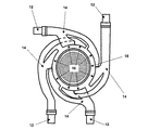
図2は、本発明の好適な実施形態の詳細を示しており、この場合、制御段は、4つのステージング弁12を有しており、各ステージング弁はノズルチャンバ14に接続されており、ノズルチャンバは、進入の円弧16を提供するように構成された下流部分を有している。各ノズルチャンバ14は2つの進入の円弧16を有しており、各ノズルチャンバ14の進入の円弧16は、別のノズルチャンバ14の進入の円弧16と交互に配置されている。この配列において、対角で向き合った2つのステージング弁12が開放される、これらの解放したステージング弁のノズルチャンバ14の端部を形成する進入の円弧16は、閉鎖したステージング弁12を有するノズルチャンバ14の進入の円弧16と交互に配置される。
FIG. 2 shows details of a preferred embodiment of the present invention, where the control stage has four
図3は、典型的な実施形態のノズルチャンバ14の詳細を示しており、このノズルチャンバは、周方向蒸気分配の有利な不均衡を提供する複数の特徴を含んでいる。図示のように、2つの進入の円弧16の周方向寸法L1,L2は異なっている。さらなる不均衡は、進入の円弧16の設計と組み合わされた、ノズルチャンバ14の分岐路15の寸法及び形状によって達成され、これらの分岐路15は、ノズルチャンバ14の蒸気流を分割し、分割された流れを進入の円弧16へ方向付ける。典型的な実施形態において、ノズルチャンバ14は、各進入の円弧16への流れに対する異なる抵抗を提供するために、寸法及び形状を介して構成されている。これは、可変供給密度を生じ、これは、羽根応力をさらに減じる不均衡を生ぜしめる。
FIG. 3 shows details of a
発明は、最も実用的かつ好適な実施形態であると考えられるものにおいて示されかつ説明されたが、発明の範囲内で変更が行われることができ、この変更は、ここに説明された詳細に限定されず、あらゆる及び全ての均等な装置を包含するために添付の請求項の完全な範囲に適合する。例えば、発明の実施形態は、片側蒸気タービンに関して説明されたが、発明は、両側蒸気タービンに等しく適用されることができる。さらに、本発明は、例示されたものとは異なる数のステージング弁12及び進入の円弧16を有する他の構成に適用されることもできる。
While the invention has been shown and described in what is considered to be the most practical and preferred embodiment, changes may be made within the scope of the invention, and this change will not be described in detail as described herein. Without limitation, it will fall within the full scope of the appended claims to include any and all equivalent devices. For example, although the embodiments of the invention have been described with respect to a single-sided steam turbine, the invention can be equally applied to double-sided steam turbines. Furthermore, the present invention may be applied to other configurations having a different number of
10 制御段、 12 ステージング弁、 14 ノズルチャンバ、 15 ノズルチャンバ分岐路、 16 進入の円弧、 18 制御段ノズル、 19 制御段羽根、 20 混合チャンバ、 22 混合チャンバ長さ、 25 ロータ、 30 標準的な羽根、 A 機械軸線、 L1,L2 進入の円弧の周方向寸法 10 control stages, 12 staging valves, 14 nozzle chambers, 15 nozzle chamber branches, 16 ingress arcs, 18 control stage nozzles, 19 control stage vanes, 20 mixing chambers, 22 mixing chamber lengths, 25 rotors, 30 standard Blade, A Machine axis, L1, L2 Circumferential dimension of the arc of entry
Claims (4)
前記タービンの負荷を制御するために、蒸気進入流を調整するための、前記タービンの周囲に周方向に分配された複数のステージング弁(12)と、
各ステージング弁(12)の下流端部に接続されたノズルチャンバ(14)と、
ノズルチャンバの下流部分を形成する少なくとも2つの進入の円弧(16)と、
前記ノズルチャンバ(14)の下流端部における、前記進入の円弧(16)における複数の制御段ノズル(18)と、が設けられている形式のものにおいて、
各ノズルチャンバ(14)の進入の円弧(16)の下流端部がそれぞれ、互いに異なる周方向寸法(L1,L2)を有することを特徴とする、蒸気タービンのための制御段。 In the control stage (10) for the steam turbine, the control stage comprises:
A plurality of staging valves (12) distributed circumferentially around the turbine for regulating steam inlet flow to control the turbine load;
A nozzle chamber (14) connected to the downstream end of each staging valve (12);
At least two entry arcs (16) forming a downstream portion of the nozzle chamber;
A plurality of control stage nozzles (18) in the approach arc (16) at the downstream end of the nozzle chamber (14),
A control stage for a steam turbine, characterized in that the downstream end of the entry arc (16) of each nozzle chamber (14) has a different circumferential dimension (L1, L2).
Applications Claiming Priority (2)
| Application Number | Priority Date | Filing Date | Title |
|---|---|---|---|
| EP08162848A EP2157287A1 (en) | 2008-08-22 | 2008-08-22 | Multifrequency control stage for improved dampening of excitation factors |
| EP08162848.9 | 2008-08-22 |
Publications (2)
| Publication Number | Publication Date |
|---|---|
| JP2010048254A true JP2010048254A (en) | 2010-03-04 |
| JP5334748B2 JP5334748B2 (en) | 2013-11-06 |
Family
ID=40792696
Family Applications (1)
| Application Number | Title | Priority Date | Filing Date |
|---|---|---|---|
| JP2009192760A Expired - Fee Related JP5334748B2 (en) | 2008-08-22 | 2009-08-24 | Multi-frequency control stage for improved damping of the excitation factor |
Country Status (5)
| Country | Link |
|---|---|
| US (1) | US8333555B2 (en) |
| EP (1) | EP2157287A1 (en) |
| JP (1) | JP5334748B2 (en) |
| CN (1) | CN101864995B (en) |
| DE (1) | DE102009036999A1 (en) |
Cited By (1)
| Publication number | Priority date | Publication date | Assignee | Title |
|---|---|---|---|---|
| JP2018066372A (en) * | 2016-09-20 | 2018-04-26 | ゼネラル・エレクトリック・カンパニイ | Fluidically controlled steam turbine inlet scroll |
Families Citing this family (8)
| Publication number | Priority date | Publication date | Assignee | Title |
|---|---|---|---|---|
| US11267916B2 (en) | 2014-02-07 | 2022-03-08 | Eastman Chemical Company | Adhesive composition comprising amorphous propylene-ethylene copolymer and polyolefins |
| US10647795B2 (en) | 2014-02-07 | 2020-05-12 | Eastman Chemical Company | Adhesive composition comprising amorphous propylene-ethylene copolymer and polyolefins |
| US9428598B2 (en) | 2014-02-07 | 2016-08-30 | Eastman Chemical Company | Amorphous propylene-ethylene copolymers |
| US10723824B2 (en) | 2014-02-07 | 2020-07-28 | Eastman Chemical Company | Adhesives comprising amorphous propylene-ethylene copolymers |
| US10308740B2 (en) | 2014-02-07 | 2019-06-04 | Eastman Chemical Company | Amorphous propylene-ethylene copolymers |
| US10696765B2 (en) | 2014-02-07 | 2020-06-30 | Eastman Chemical Company | Adhesive composition comprising amorphous propylene-ethylene copolymer and propylene polymer |
| US11156152B2 (en) | 2018-02-27 | 2021-10-26 | Borgwarner Inc. | Waste heat recovery system with nozzle block including geometrically different nozzles and turbine expander for the same |
| CN111927573B (en) * | 2020-08-24 | 2024-03-15 | 中国长江动力集团有限公司 | Structure, system and control method of turbine adjusting stage nozzle set |
Citations (6)
| Publication number | Priority date | Publication date | Assignee | Title |
|---|---|---|---|---|
| GB295639A (en) * | 1927-08-15 | 1928-09-13 | International General Electric Company Incorporated | |
| US2294127A (en) * | 1941-04-10 | 1942-08-25 | Westinghouse Electric & Mfg Co | Turbine nozzle chamber construction |
| JPS5465203A (en) * | 1977-11-01 | 1979-05-25 | Toshiba Corp | Nozzle cut-out governor for steam turbine |
| JPS5768505A (en) * | 1980-10-14 | 1982-04-26 | Toshiba Corp | Steam guide tube for steam tubbine |
| JPS5915603A (en) * | 1982-07-15 | 1984-01-26 | Hitachi Ltd | Nozzle box for steam turbine |
| JPS63302103A (en) * | 1987-05-15 | 1988-12-09 | ウエスチングハウス・エレクトリック・コーポレーション | Partial feed-in high pressure steam turbine |
Family Cites Families (6)
| Publication number | Priority date | Publication date | Assignee | Title |
|---|---|---|---|---|
| FR724732A (en) * | 1930-10-20 | 1932-05-02 | Brown | Distributor for steam or gas turbines |
| US1894117A (en) * | 1931-10-15 | 1933-01-10 | Gen Electric | Elastic fluid turbine |
| US2186952A (en) * | 1938-06-21 | 1940-01-16 | Gen Electric | Elastic fluid turbine |
| US5080558A (en) | 1990-06-07 | 1992-01-14 | Westinghouse Electric Corp. | Control stage nozzle vane for use in partial arc operation |
| DE4214775A1 (en) * | 1992-05-04 | 1993-11-11 | Abb Patent Gmbh | Steam turbine with a rotary valve |
| US6402465B1 (en) * | 2001-03-15 | 2002-06-11 | Dresser-Rand Company | Ring valve for turbine flow control |
-
2008
- 2008-08-22 EP EP08162848A patent/EP2157287A1/en not_active Withdrawn
-
2009
- 2009-08-12 DE DE102009036999A patent/DE102009036999A1/en not_active Ceased
- 2009-08-21 CN CN200910170943.8A patent/CN101864995B/en not_active Expired - Fee Related
- 2009-08-21 US US12/545,238 patent/US8333555B2/en active Active
- 2009-08-24 JP JP2009192760A patent/JP5334748B2/en not_active Expired - Fee Related
Patent Citations (6)
| Publication number | Priority date | Publication date | Assignee | Title |
|---|---|---|---|---|
| GB295639A (en) * | 1927-08-15 | 1928-09-13 | International General Electric Company Incorporated | |
| US2294127A (en) * | 1941-04-10 | 1942-08-25 | Westinghouse Electric & Mfg Co | Turbine nozzle chamber construction |
| JPS5465203A (en) * | 1977-11-01 | 1979-05-25 | Toshiba Corp | Nozzle cut-out governor for steam turbine |
| JPS5768505A (en) * | 1980-10-14 | 1982-04-26 | Toshiba Corp | Steam guide tube for steam tubbine |
| JPS5915603A (en) * | 1982-07-15 | 1984-01-26 | Hitachi Ltd | Nozzle box for steam turbine |
| JPS63302103A (en) * | 1987-05-15 | 1988-12-09 | ウエスチングハウス・エレクトリック・コーポレーション | Partial feed-in high pressure steam turbine |
Cited By (2)
| Publication number | Priority date | Publication date | Assignee | Title |
|---|---|---|---|---|
| JP2018066372A (en) * | 2016-09-20 | 2018-04-26 | ゼネラル・エレクトリック・カンパニイ | Fluidically controlled steam turbine inlet scroll |
| JP7053196B2 (en) | 2016-09-20 | 2022-04-12 | ゼネラル・エレクトリック・カンパニイ | Fluid-controlled steam turbine inlet scroll |
Also Published As
| Publication number | Publication date |
|---|---|
| JP5334748B2 (en) | 2013-11-06 |
| US20100047064A1 (en) | 2010-02-25 |
| CN101864995B (en) | 2015-09-30 |
| DE102009036999A1 (en) | 2010-02-25 |
| CN101864995A (en) | 2010-10-20 |
| US8333555B2 (en) | 2012-12-18 |
| EP2157287A1 (en) | 2010-02-24 |
Similar Documents
| Publication | Publication Date | Title |
|---|---|---|
| JP5334748B2 (en) | Multi-frequency control stage for improved damping of the excitation factor | |
| EP2589751B1 (en) | Turbine last stage flow path | |
| RU2638495C2 (en) | Turbine nozzle blade, turbine and aerodynamic portion of turbine nozzle blade | |
| EP1493900B1 (en) | Guide vane assembly for a gas turbine engine | |
| US8636463B2 (en) | Interior cooling channels | |
| US7607890B2 (en) | Robust microcircuits for turbine airfoils | |
| US8132417B2 (en) | Cooling of a gas turbine engine downstream of combustion chamber | |
| WO2012086044A1 (en) | Flow path structure and gas turbine exhaust diffuser | |
| US10006467B2 (en) | Assembly for a fluid flow machine | |
| GB2408546A (en) | Compressor casing treatment slots | |
| CA2849651A1 (en) | Axial turbomachine stator with ailerons at the blade roots | |
| RU2518703C2 (en) | Multistage radial turbine | |
| CZ20023684A3 (en) | Steam turbine inlet system, enhancing steam chamber and method for enhancing the steam turbine inlet system | |
| RU2538215C2 (en) | Outlet unit for steam turbine | |
| US20140356143A1 (en) | Assembly for a fluid flow machine | |
| US9664204B2 (en) | Assembly for a fluid flow machine | |
| US8545170B2 (en) | Turbo machine efficiency equalizer system | |
| JP2011099438A (en) | Steampath flow separation reduction system | |
| US10738624B2 (en) | Rotor device of a turbomachine | |
| US10774664B2 (en) | Plenum for cooling turbine flowpath components and blades | |
| US10508661B2 (en) | Gas turbine compressor | |
| US20140363277A1 (en) | Assembly for a fluid flow machine | |
| JP2011137413A (en) | Steam turbine | |
| JP6201548B2 (en) | Rotating machine | |
| JP2014194221A (en) | Fluid channel structure and gas turbine exhaust diffuser |
Legal Events
| Date | Code | Title | Description |
|---|---|---|---|
| RD04 | Notification of resignation of power of attorney |
Free format text: JAPANESE INTERMEDIATE CODE: A7424 Effective date: 20101227 |
|
| RD04 | Notification of resignation of power of attorney |
Free format text: JAPANESE INTERMEDIATE CODE: A7424 Effective date: 20101228 |
|
| A621 | Written request for application examination |
Free format text: JAPANESE INTERMEDIATE CODE: A621 Effective date: 20120820 |
|
| TRDD | Decision of grant or rejection written | ||
| A01 | Written decision to grant a patent or to grant a registration (utility model) |
Free format text: JAPANESE INTERMEDIATE CODE: A01 Effective date: 20130701 |
|
| A61 | First payment of annual fees (during grant procedure) |
Free format text: JAPANESE INTERMEDIATE CODE: A61 Effective date: 20130730 |
|
| R150 | Certificate of patent or registration of utility model |
Ref document number: 5334748 Country of ref document: JP Free format text: JAPANESE INTERMEDIATE CODE: R150 Free format text: JAPANESE INTERMEDIATE CODE: R150 |
|
| S533 | Written request for registration of change of name |
Free format text: JAPANESE INTERMEDIATE CODE: R313533 |
|
| R350 | Written notification of registration of transfer |
Free format text: JAPANESE INTERMEDIATE CODE: R350 |
|
| R250 | Receipt of annual fees |
Free format text: JAPANESE INTERMEDIATE CODE: R250 |
|
| R250 | Receipt of annual fees |
Free format text: JAPANESE INTERMEDIATE CODE: R250 |
|
| R250 | Receipt of annual fees |
Free format text: JAPANESE INTERMEDIATE CODE: R250 |
|
| R250 | Receipt of annual fees |
Free format text: JAPANESE INTERMEDIATE CODE: R250 |
|
| LAPS | Cancellation because of no payment of annual fees |