JP2010047924A - Stepladder - Google Patents
Stepladder Download PDFInfo
- Publication number
- JP2010047924A JP2010047924A JP2008211475A JP2008211475A JP2010047924A JP 2010047924 A JP2010047924 A JP 2010047924A JP 2008211475 A JP2008211475 A JP 2008211475A JP 2008211475 A JP2008211475 A JP 2008211475A JP 2010047924 A JP2010047924 A JP 2010047924A
- Authority
- JP
- Japan
- Prior art keywords
- leg
- movable
- legs
- movable step
- stepladder
- Prior art date
- Legal status (The legal status is an assumption and is not a legal conclusion. Google has not performed a legal analysis and makes no representation as to the accuracy of the status listed.)
- Granted
Links
- 210000001364 upper extremity Anatomy 0.000 claims abstract description 9
- 230000001429 stepping effect Effects 0.000 description 10
- 230000000295 complement effect Effects 0.000 description 7
- 229910052751 metal Inorganic materials 0.000 description 3
- 239000002184 metal Substances 0.000 description 3
- 229910052782 aluminium Inorganic materials 0.000 description 2
- XAGFODPZIPBFFR-UHFFFAOYSA-N aluminium Chemical compound [Al] XAGFODPZIPBFFR-UHFFFAOYSA-N 0.000 description 2
- 230000000052 comparative effect Effects 0.000 description 2
- 238000001125 extrusion Methods 0.000 description 2
- 239000000463 material Substances 0.000 description 1
- NJPPVKZQTLUDBO-UHFFFAOYSA-N novaluron Chemical compound C1=C(Cl)C(OC(F)(F)C(OC(F)(F)F)F)=CC=C1NC(=O)NC(=O)C1=C(F)C=CC=C1F NJPPVKZQTLUDBO-UHFFFAOYSA-N 0.000 description 1
- 230000010355 oscillation Effects 0.000 description 1
- 239000011435 rock Substances 0.000 description 1
Images


Landscapes
- Ladders (AREA)
Abstract
Description
この発明は、例えば、高所作業に用いられる脚立に関する。 The present invention relates to a stepladder used for work at a high place, for example.
この種の脚立としては、互いに開閉自在に連結されている前後の脚を備えており、各脚が、互いに左右方向に間隔をおいてのびた左右一対の支柱と、両支柱に渡されている踏ざんとを備えているものが知られている。 This type of stepladder has front and rear legs that are connected to each other so as to be openable and closable. Each leg has a pair of left and right support columns spaced apart from each other in the left and right direction and a step that is passed to both support columns. What is equipped with a gap is known.
脚立を使用する場合、踏ざんの幅が広いほど安定作業を行い易い。脚立の組立は、両支柱内に踏ざんの左右両端部が挿入された状態で、双方が互いに固定される工法が取られることが多い。その場合、踏ざんの幅は、支柱の前後方向の幅以下でなければならず、踏ざんの幅を広くすることに限界があった。 When using a stepladder, the wider the step, the easier it is to perform stable work. In many cases, the stepladder is assembled in such a manner that both the left and right ends of the step are inserted into the two columns, and both are fixed to each other. In that case, the width of the step must be less than or equal to the width in the front-rear direction of the column, and there was a limit to increasing the width of the step.
一方、踏ざんの幅を広くするために、支柱に挿入される、踏ざんの左右両端部を除いて、踏ざんの長さ方向中間部に、両支柱間から前後いずれかの側に突出させられた延長部が設けられ、延長部の分、踏ざんの幅を拡げようとする例も知られている。 On the other hand, in order to widen the width of the step, except for the left and right ends of the step, which are inserted into the column, the middle of the step is projected from either side of the column to either the front or back side. There is also an example in which an extended portion is provided, and the width of the step is increased by the amount of the extended portion.
しかしながら、この例においても、踏ざんの幅を広くすることに限界があった。その理由は、つぎの通りである。脚立を閉鎖状態にした場合、脚立の輸送・保管等の都合で、前後の脚の下端部同士は当接させられることが好ましい。この場合、脚立の閉鎖動作を行う際に、踏ざんの幅を広くしすぎると、前後の脚の踏ざんの延長部先端同士が衝突し、前後の脚の下端部同士が完全に当接させることができなくなってしまう。 However, even in this example, there was a limit to increasing the width of the step. The reason is as follows. When the stepladder is in a closed state, it is preferable that the lower end portions of the front and rear legs are brought into contact with each other for the convenience of transportation and storage of the stepladder. In this case, if the width of the step is made too wide when the stepladder is closed, the tips of the extension portions of the front and rear legs collide with each other and the lower ends of the front and rear legs are completely brought into contact with each other. It becomes impossible to do.
この発明の目的は、脚立の閉鎖動作を行う際に、前後の脚の踏ざん同士が衝突して閉鎖動作を妨げることを無くし、踏ざんの幅を可及的に広くできる脚立を提供することにある。 An object of the present invention is to provide a stepladder that can prevent the stepping action of the front and rear legs from colliding with each other when the stepping action is closed, thereby preventing the stepping action and making the width of the stepping step as wide as possible. It is in.
この発明による脚立は、左右方向にのびた開閉軸線を中心として互いに開閉自在に連結されている前後の脚を備えており、各脚が、互いに左右方向に間隔をおいてのびた左右一対の支柱と、両支柱に渡されている踏ざんとを備えており、各脚の踏ざんが、固定踏ざんおよび可動踏ざんよりなり、各脚の固定踏ざんの左右両端部が、左右対応する側の支柱に固定されており、前脚の可動踏ざんが、前脚の固定踏ざんの後縁部に、後脚の可動踏ざんが、後脚の固定踏ざんの前縁部に、上記開閉軸線と平行にのびた揺動軸線を中心として、それぞれ揺動自在に連結されており、両脚の開放姿勢から閉鎖姿勢に向かう閉鎖動作を行わせることによって、両脚の踏ざんの可動踏ざん同士が、互いに接触しかつ押圧されて、両脚の可動踏ざんが上向きに揺動可能であるものである。 The stepladder according to the present invention includes front and rear legs that are connected to each other so as to be openable and closable around an open / close axis extending in the left-right direction, and each leg includes a pair of left and right support columns spaced from each other in the left-right direction; Steps for each leg consist of a fixed step and a movable step, and the left and right ends of the fixed step for each leg are on the left and right sides The movable leg of the front leg is at the rear edge of the stationary leg of the front leg, and the movable leg of the rear leg is at the front edge of the stationary leg of the rear leg, parallel to the opening / closing axis. Centering on the extended swing axis, they are connected to each other so that they can swing, and by moving the both legs from the open position to the closed position, the movable steps of the steps of both legs come into contact with each other and When pressed, the movable step on both legs swings upward Possible are those that are.
この発明による脚立では、両脚の閉鎖動作にともない、前後の脚の可動踏ざん同士が、互いに接触しかつ押圧されて、上向きに揺動させられる。したがって、脚立の閉鎖動作を行う際に、前後の脚の踏ざん同士が衝突して、脚の閉鎖動作を妨げることが避けられる。したがって、踏ざんの幅を広くすることができる。 In the stepladder according to the present invention, with the closing operation of both legs, the movable steps of the front and rear legs are brought into contact with each other and pressed to be swung upward. Therefore, when the stepladder closing operation is performed, it is possible to prevent the stepping of the front and rear legs from colliding with each other and hindering the leg closing operation. Therefore, the width of the step can be increased.
さらに、各脚の可動踏ざんの下向きの揺動を規制するストッパを備えており、両脚の開放時において、ストッパによって、同可動踏ざんの下向きの揺動が規制された状態で、各脚の踏ざんの固定踏ざんの頂面および可動踏ざんの頂面が、面一に保持可能であると、脚立の使用時に、広い踏み面を安定して確保することができる。 In addition, a stopper is provided for restricting the downward swing of each leg of the movable step, and when the legs are opened, the downward swing of the movable step is restricted by the stopper. If the top surface of the stationary step and the top surface of the movable step can be held flush, a wide tread surface can be stably secured when the stepladder is used.
また、各脚の可動踏ざんの下向きの揺動が規制された状態で、両脚の開放姿勢から閉鎖姿勢に向かう閉鎖動作を行わせる際に、両脚の可動踏ざんの先端同士が、互いに接触しかつ押圧されるようになされていると、両脚の可動踏ざんを安定かつ確実に上向きに揺動させることができる。 In addition, when the downward swing of the movable step of each leg is restricted, the tip of the movable step of both legs comes into contact with each other when performing the closing operation from the open position of both legs to the closed position. And if it is made to press, the movable step of both legs can be rock | fluctuated upwards stably and reliably.
また、ストッパによって、両脚の一方の可動踏ざんだけが下向きの揺動が規制された状態で、両脚の開放姿勢から閉鎖姿勢に向かう閉鎖動作を行わせる際に、両脚の一方の可動踏ざんの先端および他方の可動踏ざんの底面が、互いに接触しかつ押圧されるようになされていると、脚立を閉鎖する際の他方の可動踏ざんの姿勢の如何に関わり無く、脚立を閉鎖することができる。 In addition, when the closing movement from the open position of both legs to the closed position is performed with only the movable step of one leg of both legs restricted by the stopper, If the tip and the bottom surface of the other movable step are in contact with each other and pressed, the stepladder can be closed regardless of the posture of the other movable step when closing the stepladder. it can.
また、他方の可動踏ざんの底面に、一方の可動踏ざんの先端との干渉を避けるための逃げが形成されていると、脚立の閉鎖動作を円滑に行うことができる。 Moreover, when the escape for avoiding interference with the tip of one movable step is formed on the bottom surface of the other step, the stepladder can be smoothly closed.
また、各支柱が、横断面コ字状をなすものであって、互いに平行に広がる対向状前後壁を有しており、各脚の両支柱が、前後壁の先端同士を相対させるように配列されており、各脚の両支柱の前後壁間に、固定踏ざんの左右両端部がそれぞれ挿入されており、前脚の両支柱の後壁の先端間から、可動踏ざんが後方に突出させられ、後脚の両支柱の前壁の先端間から、可動踏ざんが前方に突出させられていることが好ましい。 Each strut has a U-shaped cross section and has opposing front and rear walls extending in parallel with each other, and both struts of each leg are arranged so that the front ends of the front and rear walls are opposed to each other. The left and right ends of the fixed step are inserted between the front and rear walls of both struts of each leg, and the movable step is projected backward from between the tips of the rear walls of both front struts. It is preferable that a movable step is projected forward from between the front ends of the front walls of both pillars of the rear leg.
この発明によれば、脚立の閉鎖動作を行う際に、前後の脚の踏ざん同士が衝突することがない、踏ざんの幅を可及的にくした脚立が提供される。 According to the present invention, there is provided a stepladder in which the width of the step is made as small as possible so that the steps of the front and rear legs do not collide when the stepladder is closed.
この発明の実施の形態を図面を参照しながらつぎに説明する。 Embodiments of the present invention will be described below with reference to the drawings.
以下の説明において、矢印Aで示す方向を前、これと反対側を後といい、左右とは、前方より見て、そのその左右の側を左右というものとする。 In the following description, the direction indicated by the arrow A is referred to as the front and the opposite side is referred to as the rear, and the left and right are the left and right sides when viewed from the front.
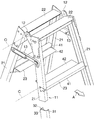
図1に示すように、脚立は、前後の脚11と、両脚11の両側面頂部にそれぞれ渡されかつ両脚11の頂部を左右方向にのびた開閉軸線Oを中心として両脚11を開閉自在に連結している一対の回転金具12と、両回転金具12のそれぞれ直下の位置で、両脚11の両側面にそれぞれ渡されている一対の開止金具13とを備えている。
As shown in FIG. 1, the stepladder is connected to the front and
両脚11は、前後の向きは逆であるが、同一構造のものである。以下、前脚11について説明し、後脚11の前脚11と対応する部分については、同一の符号を付して、その説明は、省略する。以下、とくに、必要の無い限り、前後の脚を識別する記載は省略する。
Both
脚11は、互いに間隔をおいてのびた左右一対の支柱21と、両支柱21の頂部に渡されている天板22と、天板22よりも下方レベルの位置で両支柱21に渡されている踏ざん23とよりなる
踏ざん23は、図1では、上段の踏ざん23のみを図示しているが、下段にも今1つの踏ざん24が渡されている(図4および図5)。
The
各支柱21は、横断面コ字状のアルミニウム押出型材製のものであって、互いに平行に拡がる対向状前後壁31、32と、これらの前後壁31、32の相対する両縁部の一方を連絡している側壁33とよりなる。両支柱21は、前後壁31、32の先端同士を相対させるように配置されている。
Each
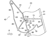
各踏ざん23は、固定踏ざん41と、固定踏ざん41の後縁部に上下揺動自在に連結されている可動踏ざん42とよりなる。固定踏ざん41および可動踏ざん42は、ともに、アルミニウム押出型材製のものである。可動踏ざん42の揺動軸線Cは、開閉軸線Oと平行にのびている。
Each
固定踏ざん41は、両支柱21の側壁33の間隔に等しいか、またはそれ以下の長さおよび各支柱21の前後壁31、32の間隔に等しいか、またはそれ以下の幅を有している。
The
固定踏ざん41の左右両端部が左右対応する側の支柱21の前後壁31、32間に挿入されている。この状態で、リベット(図示略)によって、両支柱21および固定踏ざん41の固定が果たされている。
The left and right ends of the
可動踏ざん42は、両支柱21の前後壁31、32の先端同士の間隔に等しい長さを有している。
The
図2および図3に、固定踏ざん41および可動踏ざん42の断面が詳細に示されている。図2に、可動踏ざん42が揺動範囲の下限に位置する状態を、図3に、その上限に位置する状態をそれぞれ示している。
2 and 3 show in detail the cross sections of the
固定踏ざん41は、横断面正方形に近い略方形筒状のものであって、頂壁51、後壁52、底壁53および前壁54よりなる。
The
可動踏ざん42は、固定踏ざん41と同様に、頂壁61、後壁62、底壁63および前壁64よりなるが、横断面三角形に近い方形筒状のものである。
Similar to the
まず、固定踏ざん41について、詳細に説明すると、頂壁51の頂面は、踏み面を形成し、これには、複数の並列状滑止リブ71が形成されている。頂壁51および後壁52の交差する角部には横断面半円弧状嵌合条溝72が後向きに形成されている。嵌合条溝72の上縁部には係合凸部73が下向きに設けられている。係合凸部73の先端面は、凸状円弧面となされている。係合凸部73の先端面のなす円弧の中心を、可動踏ざん42の揺動軸線Cが通っている。嵌合条溝72の底面は、同揺動中心Cを中心とする凹状円弧面に形成されている。
First, the fixed
後壁52および底壁53の交差する角部には、後方および下方に突出させられた横断面略逆L字状ストッパ突条74が設けられている。ストッパ突条74の基部上方には補完条溝75が形成されている。ストッパ突条74の基部前方には、可動踏ざん42の揺動軸線Cを中心として、円弧状に広がるガイド壁部76が設けられている。
At the corners where the
つぎに、可動踏ざん42について説明する。頂壁61の頂面には、固定踏ざん41の踏み面に対応して、並列状滑止リブ81が形成されている。前壁64は、固定踏ざん41の後壁52の高さとほぼ等しく、これと相対させられている。頂壁61および前壁64の交差する角部には、嵌合条溝72にはめ入れられている横断面略T字状嵌合突条82が前方突出状に設けられている。嵌合突条82の基部には、係合凸部73を前方から係合させた係合凹部83が上向きに形成されている。前壁64の前面下端近くには、補完条溝75に対応する補完突条84が設けられている。底壁53は、平坦部85およびこれの後縁に連なる凹状円弧部86よりなる。円弧部86の前縁に連なって、凸円弧状カバー壁部87が設けられている。カバー壁部87のなす円弧の中心は、可動踏ざん42の揺動軸線Cと一致させられている。カバー壁部87の前縁部には係合凸縁部88が上向きに設けられている。後壁52は、全体的に平坦であって、後斜め下向きに傾斜させられている。
Next, the
固定踏ざん41および可動踏ざん42を相対的に長さ方向にスライドさせることによって、嵌合条溝72および嵌合突条82が嵌合され、これにより、固定踏ざん41および可動踏ざん42の連結が果たされている。固定踏ざん41および可動踏ざん42が連結された状態で、可動踏ざん42が両支柱21の後壁52から後方に突出させられている。
By sliding the fixed
図2では、補完条溝75および補完突条84が互いに補完し合っている。ガイド壁部76にその下側からカバー壁部87が被覆されている。係合凸縁部88の先端は、ガイド壁部76に摺接させられている。補完突条84よりも下方の部分がストッパ突条74の先端後向面に前側から当接させられ、これにより、可動踏ざん42の下向き揺動が規制されている。換言するならば、ストッパ突条74の先端後向面が可動踏ざん42の下限ストッパ91を形成している。
In FIG. 2, the
図3では、固定踏ざん41の後壁52および可動踏ざん42の前壁64間に下向きに大きく広がる開口を形成しており、この開口にカバー壁部87が被覆されている。これにより、同後壁52および前壁64間に指等が挟まれることを防止できる。ストッパ突条74の基端前向面に係合凸縁部88が後側から当接させられ、これにより、可動踏ざん42の上向き揺動が規制されている。換言するならば、ストッパ突条74の基端前向面が可動踏ざん42の上限ストッパ92を形成している。
In FIG. 3, an opening that extends greatly downward is formed between the
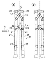
つぎに、図4および図5を参照しながら、脚11立の開閉動作を説明する。図4および図5において、その右側を前、これと反対側を後というものとする。
Next, the opening / closing operation of the
図5(a)は、脚立の使用時を示し、前後の脚11は開放状態である。前後の脚11の水平線に対する角度θ1は、約75°である。前後の脚11の踏ざん23は、いずれも水平である。すなわち、各踏ざん23の固定踏ざん41および可動踏ざん42の頂面は、水平な同一平面に含まれている。下限ストッパ91によって、可動踏ざん42の下向きの揺動が規制されている。
FIG. 5A shows the stepladder in use, and the front and
図5(a)に示す状態から前後の脚11を閉じていくと、両可動踏ざん42の頂面は同一面に含まれたままその水平線に対する角度を増加させていく。やがて、図5(b)に示すように、前後の脚11の踏ざん23の先端同士が初めて接触させられる。このときに、各踏ざん23の固定踏ざん41および可動踏ざん42の頂面が水平線に対してなす角度θ2は、約13°である。この状態から、両脚11をさらに閉じる方向に押圧すると、両踏ざん23の接触点Sは、各可動踏ざん42の揺動軸線Cよりも上方レベルに位置させられているため、両脚11に作用させられる押圧力の一部は、両可動踏ざん42の先端部を上向きに持ち上げるように作用する。
When the front and
両可動踏ざん42の先端部が持ち上げられていくにしたがって、両可動踏ざん42の先端部を接触させたままで、固定踏ざん41の頂面および可動踏ざん42の頂面は、面一であったときの180°からその角度を次第に狭めていく。図5(c)では、両脚11が互いに平行となっている。つまり、両脚11の水平線に対する角度は、90°である。
As the tips of the two
図5(d)では、両脚11が完全に閉じられていて、両脚11の下端同士が接触させられている。このときに、両脚11の水平線に対する角度θ3は、90°を、約7°程度超えている。両可動踏ざん42の底面同士は、双方の間に若干間隔をおいて、ほぼ垂直面内においてに相対させられている。
In FIG.5 (d), both the
以上は、両脚11を閉鎖するに際し、両可動踏ざん42が可動範囲の下限に位置させられている場合の説明である。ところが、両脚11を閉鎖するに際し、両可動踏ざん42がその下限に位置させられているとは限らず、両可動踏ざん42の少なくともいずれか一方がその揺動範囲のどこかに位置させられている可能性もある。
The above is an explanation of the case where both the
図5は、両脚11を閉鎖するに際し、後側の可動踏ざん42が上限ストッパ92によってその上向きの揺動が規制され、前側の可動踏ざん42が下限ストッパ91によってその下向きの揺動が規制されているケースを示すものである。
FIG. 5 shows that when the
図5(a)に、両可動踏ざん42が初めて接触させられたときの状態が示されている。後側の可動踏ざん42の底面に前側の可動踏ざん42の先端部が接触させられている。この状態から、さらに、両脚11が閉じられていくと、後側の可動踏ざん42の底面に前側の可動踏ざん42の先端部が接触させらたまま、後側の可動踏ざん42の底面にそって前側の可動踏ざん42の先端部が押し上げられていく。このときの様子が、図5(b)に示されている。最終的に両脚11が閉じたときは、図4(d)に示す通りである。
FIG. 5 (a) shows a state when the two
ここで、後側の可動踏ざん42の底面にそって前側の可動踏ざん42が移動していくときの様子を詳しく検証する。
Here, the manner in which the front
図6において、開閉軸線Oを中心とする揺動軸線Cの回転半径R上に、3つの第1〜第3揺動軸線C1、C2、C3が前から後にかけてプロットされている。第1〜第3揺動軸線C1、C2、C3に対応する、後側および前側を可動踏ざん42の3つの第1〜第3接触点S1、S2、S3が下から順に示されている。これらの第1〜第3接触点S1、S2、S3は、円弧部86上にある。第1接触点S1は、双方の可動踏ざん42が最初に接触する点である。第3接触点S3は、双方の可動踏ざん42が最終的に接触し、そこから離れていく点である。第2接触点S2は、第1接触点S1および第3接触点S3の中間点で、第1接触点S1および第3接触点S3からの距離はほぼ等しい。このことは、両脚11が閉じられる際に、揺動軸線C1、C2、C3が移動する距離と、後側の可動踏ざん42の円弧部86にそって前側の可動踏ざん42の先端が移動する距離S1、S2、S3とは釣り合っており、その際の前側の可動踏ざん42の揺動速度が一定であることを意味する。つまり、可動踏ざん42を押上げるために作用させられる押上力が、例えば、摩擦係数等の関係から、一定で、可動踏ざん42に無理な力が作用させられないのである。
In FIG. 6, three first to third oscillating axes C1, C2, and C3 are plotted from the front to the rear on the rotation radius R of the oscillating axis C with the opening / closing axis O as the center. Three first to third contact points S1, S2, S3 of the
比較例として、後側の可動踏ざん42の底面に円弧部86が無くて、後側の可動踏ざん42の底面全体が平坦である場合を想定する。図7に示すように、第1接触点S1および第3接触点S3の位置は、図6に示す場合と同じである。ところが、第1接触点S1および第3接触点S3の中間に第4接触点S4が示されている。第4接触点S4は、第2接触点S2に対応するものであるが、第1接触点S1から第4接触点S4までの距離は、第3接触点S3から第4接触点S4までの距離よりも大である。このことは、第1接触点S1から第4接触点S4まで、前側の可動踏ざん42の先端部はかなり速い速度で移動させられ、その後は、かなり遅い速度で移動させられる。この間に、前側の可動踏ざん42の先端部には、双方の可動踏ざん42間に作用する摩擦等による無理な力が加わることを意味する。
As a comparative example, it is assumed that there is no
図6および図7から分かることは、円弧部86が、前側の可動踏ざん42のスムースな揺動を妨げない逃げを形成し、双方の可動踏ざん42が互いに干渉し合わないようになっていることが分かる。
6 and 7, it can be seen that the
11 脚
21 支柱
23 踏ざん
41 固定踏ざん
42 可動踏ざん
O 開閉軸線
C 揺動軸線
11 legs
21 Prop
23 stepping on
41 Fixed step
42 Movable step
O Open / close axis
C Oscillation axis
Claims (6)
Priority Applications (1)
| Application Number | Priority Date | Filing Date | Title |
|---|---|---|---|
| JP2008211475A JP5457648B2 (en) | 2008-08-20 | 2008-08-20 | stepladder |
Applications Claiming Priority (1)
| Application Number | Priority Date | Filing Date | Title |
|---|---|---|---|
| JP2008211475A JP5457648B2 (en) | 2008-08-20 | 2008-08-20 | stepladder |
Publications (2)
| Publication Number | Publication Date |
|---|---|
| JP2010047924A true JP2010047924A (en) | 2010-03-04 |
| JP5457648B2 JP5457648B2 (en) | 2014-04-02 |
Family
ID=42065213
Family Applications (1)
| Application Number | Title | Priority Date | Filing Date |
|---|---|---|---|
| JP2008211475A Active JP5457648B2 (en) | 2008-08-20 | 2008-08-20 | stepladder |
Country Status (1)
| Country | Link |
|---|---|
| JP (1) | JP5457648B2 (en) |
Cited By (2)
| Publication number | Priority date | Publication date | Assignee | Title |
|---|---|---|---|---|
| JP2011084869A (en) * | 2009-10-13 | 2011-04-28 | Hasegawa Kogyo Co Ltd | Stepladder |
| KR20200112125A (en) * | 2019-03-21 | 2020-10-05 | 원종심 | Foot protection device for folding ladder |
Citations (3)
| Publication number | Priority date | Publication date | Assignee | Title |
|---|---|---|---|---|
| JPS5290241U (en) * | 1975-12-27 | 1977-07-06 | ||
| JPS59126099U (en) * | 1983-02-15 | 1984-08-24 | 椎名 正二 | A stepladder with a stable step on the horizontal rung |
| JP2001193276A (en) * | 2000-01-17 | 2001-07-17 | Hasegawa Kogyo Co Ltd | Working table |
-
2008
- 2008-08-20 JP JP2008211475A patent/JP5457648B2/en active Active
Patent Citations (3)
| Publication number | Priority date | Publication date | Assignee | Title |
|---|---|---|---|---|
| JPS5290241U (en) * | 1975-12-27 | 1977-07-06 | ||
| JPS59126099U (en) * | 1983-02-15 | 1984-08-24 | 椎名 正二 | A stepladder with a stable step on the horizontal rung |
| JP2001193276A (en) * | 2000-01-17 | 2001-07-17 | Hasegawa Kogyo Co Ltd | Working table |
Cited By (3)
| Publication number | Priority date | Publication date | Assignee | Title |
|---|---|---|---|---|
| JP2011084869A (en) * | 2009-10-13 | 2011-04-28 | Hasegawa Kogyo Co Ltd | Stepladder |
| KR20200112125A (en) * | 2019-03-21 | 2020-10-05 | 원종심 | Foot protection device for folding ladder |
| KR102180074B1 (en) * | 2019-03-21 | 2020-11-17 | 원종심 | Foot protection device for folding ladder |
Also Published As
| Publication number | Publication date |
|---|---|
| JP5457648B2 (en) | 2014-04-02 |
Similar Documents
| Publication | Publication Date | Title |
|---|---|---|
| US9132778B2 (en) | Luggage board movement mechanism | |
| JP5457648B2 (en) | stepladder | |
| JP6853105B2 (en) | Folding door | |
| JP5588654B2 (en) | stepladder | |
| JP6034173B2 (en) | Folding container | |
| JP6370656B2 (en) | Folding container | |
| JP2012219589A (en) | Stepladder | |
| JP5517346B2 (en) | Door stopper device | |
| JP4711338B2 (en) | Folding container | |
| JP5174437B2 (en) | Folding container | |
| JP4332884B2 (en) | stepladder | |
| KR20150084225A (en) | Deck truck | |
| JP6588268B2 (en) | container | |
| JP2015132133A (en) | Fixture | |
| JP4457392B2 (en) | Assembled plastic container | |
| JP6974839B2 (en) | Container with lid | |
| JP6588267B2 (en) | container | |
| JP6239321B2 (en) | Folding container | |
| TW201537602A (en) | Keyswitch structure | |
| JP3625762B2 (en) | Foldable container with divider | |
| JP6945853B2 (en) | Folding container | |
| JP3210040U (en) | Box pallet | |
| KR200468788Y1 (en) | Door provided with table | |
| JP5103208B2 (en) | Workbench | |
| KR20160147412A (en) | Double rotating shaft structure for lean back cover electronic apparatus |
Legal Events
| Date | Code | Title | Description |
|---|---|---|---|
| A621 | Written request for application examination |
Free format text: JAPANESE INTERMEDIATE CODE: A621 Effective date: 20110805 |
|
| A977 | Report on retrieval |
Free format text: JAPANESE INTERMEDIATE CODE: A971007 Effective date: 20121012 |
|
| A131 | Notification of reasons for refusal |
Free format text: JAPANESE INTERMEDIATE CODE: A131 Effective date: 20130226 |
|
| A521 | Request for written amendment filed |
Free format text: JAPANESE INTERMEDIATE CODE: A523 Effective date: 20130409 |
|
| TRDD | Decision of grant or rejection written | ||
| A01 | Written decision to grant a patent or to grant a registration (utility model) |
Free format text: JAPANESE INTERMEDIATE CODE: A01 Effective date: 20140107 |
|
| A61 | First payment of annual fees (during grant procedure) |
Free format text: JAPANESE INTERMEDIATE CODE: A61 Effective date: 20140110 |
|
| R150 | Certificate of patent or registration of utility model |
Ref document number: 5457648 Country of ref document: JP Free format text: JAPANESE INTERMEDIATE CODE: R150 Free format text: JAPANESE INTERMEDIATE CODE: R150 |
|
| R250 | Receipt of annual fees |
Free format text: JAPANESE INTERMEDIATE CODE: R250 |
|
| R250 | Receipt of annual fees |
Free format text: JAPANESE INTERMEDIATE CODE: R250 |
|
| R250 | Receipt of annual fees |
Free format text: JAPANESE INTERMEDIATE CODE: R250 |
|
| R250 | Receipt of annual fees |
Free format text: JAPANESE INTERMEDIATE CODE: R250 |
|
| R250 | Receipt of annual fees |
Free format text: JAPANESE INTERMEDIATE CODE: R250 |
|
| R250 | Receipt of annual fees |
Free format text: JAPANESE INTERMEDIATE CODE: R250 |
|
| R250 | Receipt of annual fees |
Free format text: JAPANESE INTERMEDIATE CODE: R250 |
|
| R250 | Receipt of annual fees |
Free format text: JAPANESE INTERMEDIATE CODE: R250 |