JP2010047348A - Reel, reel with embossed tape, and manufacturing method of semiconductor device - Google Patents
Reel, reel with embossed tape, and manufacturing method of semiconductor device Download PDFInfo
- Publication number
- JP2010047348A JP2010047348A JP2008211973A JP2008211973A JP2010047348A JP 2010047348 A JP2010047348 A JP 2010047348A JP 2008211973 A JP2008211973 A JP 2008211973A JP 2008211973 A JP2008211973 A JP 2008211973A JP 2010047348 A JP2010047348 A JP 2010047348A
- Authority
- JP
- Japan
- Prior art keywords
- flanges
- hub
- pair
- reel
- protrusions
- Prior art date
- Legal status (The legal status is an assumption and is not a legal conclusion. Google has not performed a legal analysis and makes no representation as to the accuracy of the status listed.)
- Granted
Links
Images

Landscapes
- Storage Of Web-Like Or Filamentary Materials (AREA)
- Wire Bonding (AREA)
Abstract
Description
本発明は、リール、エンボステープ付きリール、及び半導体装置の製造方法に関する。 The present invention relates to a reel, a reel with an embossed tape, and a method for manufacturing a semiconductor device.
エンボステープ等のテープ状部材を保管あるいは運搬して出荷梱包するに際しては、前記テープ状部材をリールに巻回して行う。このようなリールは、通常、前記テープ状部材を巻回するためのハブと、このハブの両端部に接続された一対のフランジとからなる。従来においては、巻回すべき前記テープ状部材の幅に応じたハブを有するリールを逐一作製して準備するようにしていた。換言すれば、前記テープ状部材の幅に応じた異なる種類(大きさ)のリールを逐一作製し、準備していた。 When a tape-like member such as an embossed tape is stored or transported and shipped and packed, the tape-like member is wound around a reel. Such a reel usually comprises a hub for winding the tape-like member and a pair of flanges connected to both ends of the hub. Conventionally, reels having hubs corresponding to the width of the tape-shaped member to be wound are produced and prepared one by one. In other words, reels of different types (sizes) corresponding to the width of the tape-shaped member were prepared and prepared one by one.
しかしながら、テープ状部材の幅に応じて独立にそれぞれ全く異なるリールを作製するとなると、製造工程が煩雑化し、各リールの製造コスト増大の原因となっていた。また、上述のようなフランジとハブとが一体化したリールは、スライド金型を用いて作製しなければならず、このスライド金型が高価なことに加えて、異なる種類(大きさ)のリール毎に異なるスライド金型を作製し、準備する必要がある。したがって、このような特殊な金型を使用しなければならないという観点からも、上述したリールの製造コストを増大させてしまう原因となっていた。 However, if reels that are completely different from each other according to the width of the tape-like member are manufactured independently, the manufacturing process becomes complicated, which causes an increase in manufacturing cost of each reel. In addition, the above-described reel in which the flange and the hub are integrated must be manufactured using a slide mold. In addition to the high cost of this slide mold, different types (sizes) of reels are used. It is necessary to prepare and prepare different slide molds for each. Therefore, from the viewpoint that such a special mold must be used, the manufacturing cost of the reel is increased.
特許文献1〜3に開示されたものにおいては、テープ状部材の幅に応じてハブの長さを調整すべく、リール全体を逐一製造しないまでも、その構成部材であるハブに関しては、複数の部材を準備し、これらを組合わせて前記テープ状部材の幅に対応していた。すなわち、前記テープ状部材の幅に対応すべく、リール全体を再構成しないまでも、その構成部材であるハブに関しては、逐一作製しなければならず、テープ状部材の幅に応じたリールの製造コストを十分に低減することができないという問題があった。
In the ones disclosed in
本発明は、確定したリール構成で異なる幅のテープ状部材の巻回を可能にし、前記テープ状部材の異なる幅に対応したリールの製造コストを低減することを目的とする。 An object of the present invention is to enable winding of tape-shaped members having different widths with a determined reel configuration, and to reduce the manufacturing cost of reels corresponding to different widths of the tape-shaped members.
本発明の一態様は、相対向するように配置された一対のフランジと、前記一対のフランジの、互いに対向する面上に取り付けられた、異なる長さを有する複数の突起と、前記一対のフランジの間に配置され、所定の材料を巻回するとともに、前記複数の突起と係合する複数の孔が形成されてなるハブとを具え、前記複数の突起を選択して前記ハブの前記孔中に係合させることにより、前記一対のフランジ間の距離を調整するように構成したことを特徴とする、リールに関する。 One embodiment of the present invention includes a pair of flanges arranged to face each other, a plurality of protrusions having different lengths attached to surfaces of the pair of flanges facing each other, and the pair of flanges And a hub formed by winding a predetermined material and having a plurality of holes engaged with the plurality of protrusions, and selecting the plurality of protrusions in the hole of the hub. The reel is configured to adjust a distance between the pair of flanges by being engaged with each other.
また、本発明の他の態様は、相対向するように配置された一対のフランジと、前記一対のフランジの一方の面上において、前記一対のフランジの他方と対向するようにして取り付けられた、異なる長さを有する複数の突起と、前記一対のフランジの前記他方の面上に取り付けられた、所定の材料を巻回するとともに、前記複数の突起と係合する複数の孔が形成されてなるハブとを具え、前記複数の突起を選択して前記ハブの前記孔中に係合させることにより、前記一対のフランジ間の距離を調整するように構成したことを特徴とする、リールに関する。 In another aspect of the present invention, a pair of flanges arranged to face each other, and on one surface of the pair of flanges, attached to face the other of the pair of flanges, A plurality of protrusions having different lengths and a plurality of holes that are wound on the other surface of the pair of flanges and wound with a predetermined material and engage with the plurality of protrusions are formed. A reel comprising: a hub, wherein the distance between the pair of flanges is adjusted by selecting the plurality of protrusions and engaging the plurality of protrusions in the hole of the hub.
さらに、本発明のその他の態様は、相対向するように配置された一対のフランジと、前記一対のフランジの、互いに対向する面上に取り付けられた、異なる長さを有する複数の突起と、前記一対のフランジの間に配置され、前記複数の突起と係合する複数の孔が形成されてなるハブと、半導体装置が収納され、前記ハブに対して巻回されたエンボステープとを具え、前記複数の突起を選択して前記ハブの前記孔中に係合させることにより、前記一対のフランジ間の距離を調整し、前記ハブに対して巻回する前記エンボステープの幅を調整するように構成したことを特徴とする、エンボステープ付きリールに関する。 Further, according to another aspect of the present invention, a pair of flanges arranged so as to face each other, a plurality of protrusions having different lengths attached to surfaces of the pair of flanges facing each other, A hub disposed between a pair of flanges and formed with a plurality of holes engaging with the plurality of protrusions; and an embossed tape that is housed in the semiconductor device and wound around the hub, A plurality of protrusions are selected and engaged in the hole of the hub, thereby adjusting a distance between the pair of flanges and adjusting a width of the embossed tape wound around the hub. The present invention relates to a reel with an embossed tape.
また、本発明の他の態様は、相対向するように配置された一対のフランジと、前記一対のフランジの一方の面上において、前記一対のフランジの他方と対向するようにして取り付けられた、異なる長さを有する複数の突起と、前記一対のフランジの前記他方の面上に取り付けられた、前記複数の突起と係合する複数の孔が形成されてなるハブと、半導体装置が収納され、前記ハブに対して巻回されたエンボステープとを具え、前記複数の突起を選択して前記ハブの前記孔中に係合させることにより、前記一対のフランジ間の距離を調整し、前記ハブに対して巻回する前記エンボステープの幅を調整するように構成したことを特徴とする、エンボステープ付きリールに関する。 In another aspect of the present invention, a pair of flanges arranged to face each other, and on one surface of the pair of flanges, attached to face the other of the pair of flanges, A plurality of protrusions having different lengths, a hub formed on the other surface of the pair of flanges and formed with a plurality of holes engaging with the plurality of protrusions, and a semiconductor device are housed, An embossed tape wound around the hub, and adjusting the distance between the pair of flanges by selecting the plurality of protrusions and engaging them in the holes of the hub. The present invention relates to a reel with an embossed tape, characterized in that the width of the embossed tape wound on the reel is adjusted.
さらに、本発明のその他の態様は、上記リールを準備する工程と、前記リールの前記ハブに対して、半導体装置を収納したエンボステープを巻回する工程と、を具えることを特徴とする、エンボステープの巻回方法に関する。 Furthermore, another aspect of the present invention includes a step of preparing the reel, and a step of winding an embossed tape containing a semiconductor device around the hub of the reel. The present invention relates to a method of winding an embossed tape.
本発明は、確定したリール構成で異なる幅のテープ状部材の巻回を可能にし、前記テープ状部材の異なる幅に対応したリールの製造コストを低減することができる。 The present invention enables winding of tape-like members having different widths with a determined reel configuration, and can reduce the manufacturing cost of reels corresponding to different widths of the tape-like members.
以下、本発明の具体的な実施形態について説明する。 Hereinafter, specific embodiments of the present invention will be described.
(第1の実施形態)
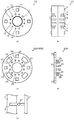
図1(a)は、本態様におけるリールを構成するハブの平面図であり、図1(b)は、図1(a)に示すハブの中央断面図である。図1(c)は、本態様のリールを構成するフランジの平面図であり、図1(d)及び(e)は、図1(c)に示すフランジの側面図である。図1(d)は、ハブに対して左方に位置するフランジを示し、図1(e)は、ハブに対して右方に位置するフランジを示している。また、図2は、リールの全体構成を示している。
(First embodiment)
Fig.1 (a) is a top view of the hub which comprises the reel in this aspect, FIG.1 (b) is a center sectional drawing of the hub shown to Fig.1 (a). FIG.1 (c) is a top view of the flange which comprises the reel of this aspect, FIG.1 (d) and (e) are side views of the flange shown in FIG.1 (c). FIG. 1D shows the flange located on the left side with respect to the hub, and FIG. 1E shows the flange located on the right side with respect to the hub. FIG. 2 shows the entire configuration of the reel.
図1(a)、(b)に示すように、本態様のリール30におけるハブ10は、略中央部において円形状の突起部材からなるフランジに対する係合部材11を有するとともに、その外周部において矩形状の突起部材からなるフランジに対する係合部材12を有している。なお、本例では、係合部材12の数は4としているが必要に応じて任意の数とすることができる。また係合部材11を円形状とし、係合部材12を矩形状としているが、必要に応じて任意の形状とすることができる。
As shown in FIGS. 1 (a) and 1 (b), the
図1(a)に示すように、係合部材11の周囲には、ハブ10の中心から外側に向けて、第1の孔13、第2の孔14及び第3の孔15がそれぞれ2つずつ形成されている。
As shown in FIG. 1A, there are two
図1(b)に示すように、孔の深さは、第1の孔13、第2の孔14及び第3の孔15の順に深くなっている。これは以下に説明するフランジ表面に形成された突起を係合させるために、前記突起の長さに対応させたものである。
As shown in FIG. 1B, the depth of the holes becomes deeper in the order of the
図1(c)、(d)に示すように、本態様のリール30におけるフランジ20A及び20Bは、略中央部において環状の凹部21が形成されているとともに、その外周部において矩形状の凹部22が形成されている。これらの凹部21及び22は、ハブ10とフランジ20A及び20Bとを組合せる際に、ハブ10の係合部材11及び12が係合するように構成されている。すなわち、以下に示すように突起によってフランジ20A及び20B間の距離を調整しないような場合は、ハブ10の係合部材11及び12が、フランジ20A及び20Bの凹部21及び22に直接係合することによって組み立てられる。
As shown in FIGS. 1C and 1D, the flanges 20 </ b> A and 20 </ b> B in the reel 30 of this aspect have an
また、図1(c)〜(e)に示すように、フランジ20A及び20Bの互いに対向する面上には、第1の突起23、第2の突起24及び第3の突起25が形成されている。突起の長さは、第1の突起23、第2の突起24及び第3の突起25の順に長くなっている。また、ハブ10とフランジ20A及び20Bとを組合せてリールを作製する場合、フランジ20A及び20Bの第1の突起23、第2の突起24及び第3の突起25は、それぞれハブ10の第1の孔13、第2の孔14及び第3の孔15に係合するので、これらの突起は、ハブ10に形成された孔の位置と合致するようにして形成する。
Further, as shown in FIGS. 1C to 1E, the
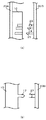
ハブ10とフランジ20A及び20Bとを組合せてリールを形成する場合、例えば、フランジ20A及び20B間を最も短くするには、第1の突起23、第2の突起24及び第3の突起25をそれぞれ第1の孔13、第2の孔14及び第3の孔15に埋め込むようにする。その場合、リールの形状は、図2(a)に示すような形状となる。この場合、上述したように、ハブ10の係合部材11及び12が、フランジ20A及び20Bの凹部21及び22に直接係合するようになる。
When a reel is formed by combining the
なお、本例では、第1の突起から第3の突起の長さ及び第1の孔から第3の孔の深さ、並びにハブ10の長さを調整することによって、フランジ20A及び20B間を例えば16mmとすることができる。
In this example, by adjusting the length of the third protrusion from the first protrusion, the depth of the third hole from the first hole, and the length of the
一方、フランジ20A及び20B間を最も長くするには、第1の突起23のみを第1の孔13中に嵌入する。この場合、ハブ10とフランジ20A及び20Bとは、第1の突起23と第1の孔13との係合によって保持されるので、図2(b)に示すように、フランジ20A及び20B間を長く設定することができる。
On the other hand, in order to make the distance between the flanges 20 </ b> A and 20 </ b> B the longest, only the
なお、本例では、第1の突起23の長さ及び第1の孔13の深さを調整することによって、フランジ20A及び20B間を例えば32mmとすることができる。
In this example, by adjusting the length of the
また、フランジ20A及び20B間を中程度の長さとするには、第1の突起23及び第2の突起24をそれぞれ第1の孔13及び第2の孔14中に嵌入する。この場合、ハブ10とフランジ20A及び20Bとは、第1の突起23と第1の孔13との係合、並びに第2の突起24と第2の孔14との係合によって保持されるので、図2(c)に示すように、フランジ20A及び20B間を中程度に長く設定することができる。
Further, in order to make the length between the
なお、本例では、第1の突起23の長さ及び第1の孔13の深さ、及び第2の突起24の長さ及び第2の孔14の深さを調整することによって、フランジ20A及び20B間を例えば24mmとすることができる。
In this example, the
このように、本態様では、一対のフランジの対向面上に異なる長さの複数の突起を形成するとともに、これら突起に対応してハブ中に複数の孔を形成し、前記ハブ中の前記孔中に嵌入させる突起を適宜選択することによって、前記一対のフランジ間の距離が調整できる。 Thus, in this aspect, a plurality of protrusions having different lengths are formed on the opposing surfaces of the pair of flanges, and a plurality of holes are formed in the hub corresponding to the protrusions, and the holes in the hub are formed. The distance between the pair of flanges can be adjusted by appropriately selecting the protrusions to be fitted therein.
また、前記突起及び前記孔は、巻回すべきテープ状部材の幅等を考慮して、リールを構成するフランジ及びハブに適宜形成するものではなく、総てのリールに対して予め画一的に形成しておくものである。したがって、巻回すべきテープ状部材の幅を考慮して、ハブ等を逐一形成することなく、確定したリール構成で異なる幅のテープ状部材の巻回を可能にすることができる。結果として、前記テープ状部材の異なる幅に対応したリールの製造コストを低減することができる。 Further, the protrusion and the hole are not appropriately formed on the flange and the hub constituting the reel in consideration of the width of the tape-like member to be wound, etc. It is to be formed. Therefore, in consideration of the width of the tape-shaped member to be wound, it is possible to wind the tape-shaped member having different widths with the determined reel configuration without forming a hub or the like one by one. As a result, the manufacturing cost of reels corresponding to different widths of the tape-like member can be reduced.
なお、本態様では、フランジ20A及び20Bに対して、長さの異なる3種類の突起23,24,25を形成し、これに対応させてハブ10に深さの異なる3種類の孔13,14,15を形成したが、突起及び孔の数は、設定すべきフランジ20A及び20Bの幅の種類に応じて任意の設定することができる。
In this embodiment, three types of
(第2の実施形態)
図3(a)は、第2の実施形態に係わるリールの構成図である。第1の実施形態では、一対のフランジ20A及び20Bを設け、この間にハブ10を配置するようにしたが、本態様では、一対のフランジの一方、すなわちフランジ20Aにハブ10を固定し、一対のフランジの他方、すなわちフランジ20Bに対して第1の突起23、第2の突起24及び第3の突起25を形成するようにしている。
(Second Embodiment)
FIG. 3A is a configuration diagram of a reel according to the second embodiment. In the first embodiment, a pair of
なお、特に図示しないが、図3(a)に示すハブ10は図1(a)、(b)に示すような態様を取る。
Although not particularly illustrated, the
本態様でも、フランジ20A及び20B間を最も短くするには、第1の突起23、第2の突起24及び第3の突起25をそれぞれ第1の孔13、第2の孔14及び第3の孔15に埋め込むようにする。その場合、リールの形状は、図2(a)に示すような形状となる。この場合、上述したように、ハブ10の係合部材11及び12が、フランジ20A及び20Bの凹部21及び22に直接係合するようになる。
Also in this embodiment, in order to make the distance between the
一方、フランジ20A及び20B間を最も長くするには、第1の突起23のみを第1の孔13中に嵌入する。この場合、ハブ10とフランジ20A及び20Bとは、第1の突起23と第1の孔13との係合によって保持されるので、図2(b)に示すように、フランジ20A及び20B間を長く設定することができる。
On the other hand, in order to make the distance between the flanges 20 </ b> A and 20 </ b> B the longest, only the
また、フランジ20A及び20B間を中程度の長さとするには、第1の突起23及び第2の突起24をそれぞれ第1の孔13及び第2の孔14中に嵌入する。この場合、ハブ10とフランジ20A及び20Bとは、第1の突起23と第1の孔13との係合、並びに第2の突起24と第2の孔14との係合によって保持されるので、図2(c)に示すように、フランジ20A及び20B間を中程度に長く設定することができる。
Further, in order to make the length between the
このように、本態様でも、一方のフランジの、他方のフランジとの対向面上に異なる長さの複数の突起を形成するとともに、これら突起に対応してハブ中に複数の孔を形成し、前記ハブ中の前記孔中に嵌入させる突起を適宜選択することによって、前記一対のフランジ間の距離が調整できるようになるものである。 Thus, also in this aspect, a plurality of protrusions with different lengths are formed on the surface of one flange facing the other flange, and a plurality of holes are formed in the hub corresponding to these protrusions. The distance between the pair of flanges can be adjusted by appropriately selecting a protrusion to be fitted into the hole in the hub.
また、前記突起及び前記孔は、巻回すべきテープ状部材の幅等を考慮して、リールを構成するフランジ及びハブに適宜形成するものではなく、総てのリールに対して予め画一的に形成しておくものである。したがって、巻回すべきテープ状部材の幅を考慮して、ハブ等を逐一形成することなく、確定したリール構成で異なる幅のテープ状部材の巻回を可能にすることができる。結果として、前記テープ状部材の異なる幅に対応したリールの製造コストを低減することができる。 Further, the protrusion and the hole are not appropriately formed on the flange and the hub constituting the reel in consideration of the width of the tape-like member to be wound, etc. It is to be formed. Therefore, in consideration of the width of the tape-shaped member to be wound, it is possible to wind the tape-shaped member having different widths with the determined reel configuration without forming a hub or the like one by one. As a result, the manufacturing cost of reels corresponding to different widths of the tape-like member can be reduced.
(第3の実施形態)
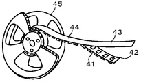
図4は、第1の実施形態及び第2の実施形態で得たリールに対して、半導体装置を収納したエンボステープを巻回した状態を示す図である。図4において、参照数字41は半導体チップを収納するポケット42を有するキャリアテープであり、参照数字43はキャリアテープ41の上側に圧着されるカバーテープであり、キャリアテープ41とカバーテープ43とが一体となってエンボステープ44を構成する。なお、参照数字45はこのエンボステープ44を巻き取るためのリールである。
(Third embodiment)
FIG. 4 is a view showing a state where an embossed tape containing a semiconductor device is wound around the reels obtained in the first embodiment and the second embodiment. In FIG. 4,
なお、本態様では、エンボステープ44の巻回状態に着目しているため、リール45の構成については簡略化している。
In this aspect, since the focus is on the winding state of the embossed
上述した第1の実施形態によれば、エンボステープ44の幅が変化した場合においても、一対のフランジの対向面上に異なる長さの複数の突起を形成するとともに、これら突起に対応してハブ中に複数の孔を形成し、前記ハブ中の前記孔中に嵌入させる突起を適宜選択することによって、前記一対のフランジ間の距離が調整できるので、確定したリール構成で異なる幅のテープ状部材の巻回を可能にすることができる。結果として、前記テープ状部材の異なる幅に対応したリールの製造コストを低減することができる。
According to the first embodiment described above, even when the width of the embossed
また、上述した第2の実施形態によれば、一方のフランジの、他方のフランジとの対向面上に異なる長さの複数の突起を形成するとともに、これら突起に対応してハブ中に複数の孔を形成し、前記ハブ中の前記孔中に嵌入させる突起を適宜選択することによって、前記一対のフランジ間の距離が調整できるので、確定したリール構成で異なる幅のテープ状部材の巻回を可能にすることができる。結果として、前記テープ状部材の異なる幅に対応したリールの製造コストを低減することができる。 Further, according to the second embodiment described above, a plurality of protrusions having different lengths are formed on the surface of one flange facing the other flange, and a plurality of protrusions are formed in the hub corresponding to these protrusions. The distance between the pair of flanges can be adjusted by forming a hole and appropriately selecting a protrusion to be fitted into the hole in the hub, so that tape-shaped members having different widths can be wound with a determined reel configuration. Can be possible. As a result, the manufacturing cost of reels corresponding to different widths of the tape-like member can be reduced.
以上、本発明を上記具体例に基づいて詳細に説明したが、本発明は上記具体例に限定されるものではなく、本発明の範疇を逸脱しない限りにおいてあらゆる変形や変更が可能である。 While the present invention has been described in detail based on the above specific examples, the present invention is not limited to the above specific examples, and various modifications and changes can be made without departing from the scope of the present invention.
例えば、上記具体例では、ハブ10内に孔を形成し、フランジ20A及び20Bに形成した突起を嵌入させて係合するようにしているが、図3(b)に示すように、ハブ11の表面に第2の突起17を形成するとともに、フランジ20Bに形成すべき突起27を受け皿状とし、ハブ11の第2の突起17とフランジ20B(20A)の突起27とを係合させるようにすることもできる。
For example, in the above specific example, a hole is formed in the
10…ハブ、11,12…係合部材、13…第1の孔、14…第2の孔、15…第3の孔、20A,20B…フランジ、21,22…凹部、23…第1の突起、24…第2の突起、25…第3の突起
DESCRIPTION OF
Claims (5)
前記一対のフランジの、互いに対向する面上に取り付けられた、異なる長さを有する複数の突起と、
前記一対のフランジの間に配置され、所定の材料を巻回するとともに、前記複数の突起と係合する深さの複数の孔が形成されてなるハブとを具え、
前記複数の突起を選択して前記ハブの前記孔中に係合させることにより、前記一対のフランジ間の距離を調整するように構成したことを特徴とする、リール。 A pair of flanges arranged to face each other;
A plurality of protrusions having different lengths mounted on opposite surfaces of the pair of flanges;
A hub that is disposed between the pair of flanges, winds a predetermined material, and has a plurality of holes formed at a depth to engage with the plurality of protrusions;
A reel configured to adjust a distance between the pair of flanges by selecting the plurality of protrusions and engaging the protrusions in the hole of the hub.
前記一対のフランジの一方の面上において、前記一対のフランジの他方と対向するようにして取り付けられた、異なる長さを有する複数の突起と、
前記一対のフランジの前記他方の面上に取り付けられた、所定の材料を巻回するとともに、前記複数の突起と係合する複数の孔が形成されてなるハブとを具え、
前記複数の突起を選択して前記ハブの前記孔中に係合させることにより、前記一対のフランジ間の距離を調整するように構成したことを特徴とする、リール。 A pair of flanges arranged to face each other;
A plurality of protrusions having different lengths attached on one surface of the pair of flanges so as to face the other of the pair of flanges;
A hub mounted on the other surface of the pair of flanges, wound with a predetermined material, and formed with a plurality of holes engaging with the plurality of protrusions;
A reel configured to adjust a distance between the pair of flanges by selecting the plurality of protrusions and engaging the protrusions in the hole of the hub.
前記一対のフランジの、互いに対向する面上に取り付けられた、異なる長さを有する複数の突起と、
前記一対のフランジの間に配置され、前記複数の突起と係合する複数の孔が形成されてなるハブと、
半導体装置が収納され、前記ハブに対して巻回されたエンボステープとを具え、
前記複数の突起を選択して前記ハブの前記孔中に係合させることにより、前記一対のフランジ間の距離を調整し、前記ハブに対して巻回する前記エンボステープの幅を調整するように構成したことを特徴とする、エンボステープ付きリール。 A pair of flanges arranged to face each other;
A plurality of protrusions having different lengths mounted on opposite surfaces of the pair of flanges;
A hub formed between the pair of flanges and formed with a plurality of holes engaging with the plurality of protrusions;
A semiconductor device is housed and comprises an embossed tape wound around the hub,
By selecting the plurality of protrusions and engaging them in the holes of the hub, the distance between the pair of flanges is adjusted, and the width of the embossed tape wound around the hub is adjusted. A reel with embossed tape, characterized in that it is constructed.
前記一対のフランジの一方の面上において、前記一対のフランジの他方と対向するようにして取り付けられた、異なる長さを有する複数の突起と、
前記一対のフランジの前記他方の面上に取り付けられた、前記複数の突起と係合する複数の孔が形成されてなるハブと、
半導体装置が収納され、前記ハブに対して巻回されたエンボステープとを具え、
前記複数の突起を選択して前記ハブの前記孔中に係合させることにより、前記一対のフランジ間の距離を調整し、前記ハブに対して巻回する前記エンボステープの幅を調整するように構成したことを特徴とする、エンボステープ付きリール。 A pair of flanges arranged to face each other;
A plurality of protrusions having different lengths attached on one surface of the pair of flanges so as to face the other of the pair of flanges;
A hub formed on the other surface of the pair of flanges and formed with a plurality of holes engaging with the plurality of protrusions;
A semiconductor device is housed and comprises an embossed tape wound around the hub,
By selecting the plurality of protrusions and engaging them in the holes of the hub, the distance between the pair of flanges is adjusted, and the width of the embossed tape wound around the hub is adjusted. A reel with embossed tape, characterized in that it is constructed.
前記リールの前記ハブに対して、半導体装置を収納したエンボステープを巻回する工程と、
を具えることを特徴とする、半導体装置の製造方法。 Preparing the reel according to claim 1 or 2,
Winding an embossed tape containing a semiconductor device around the hub of the reel;
A method of manufacturing a semiconductor device, comprising:
Priority Applications (1)
| Application Number | Priority Date | Filing Date | Title |
|---|---|---|---|
| JP2008211973A JP4660577B2 (en) | 2008-08-20 | 2008-08-20 | Reel, reel with embossed tape, and method for manufacturing semiconductor device |
Applications Claiming Priority (1)
| Application Number | Priority Date | Filing Date | Title |
|---|---|---|---|
| JP2008211973A JP4660577B2 (en) | 2008-08-20 | 2008-08-20 | Reel, reel with embossed tape, and method for manufacturing semiconductor device |
Related Child Applications (1)
| Application Number | Title | Priority Date | Filing Date |
|---|---|---|---|
| JP2010289474A Division JP5073047B2 (en) | 2010-12-27 | 2010-12-27 | Method for manufacturing reel and method for manufacturing reel with embossed tape |
Publications (3)
| Publication Number | Publication Date |
|---|---|
| JP2010047348A true JP2010047348A (en) | 2010-03-04 |
| JP2010047348A5 JP2010047348A5 (en) | 2010-07-15 |
| JP4660577B2 JP4660577B2 (en) | 2011-03-30 |
Family
ID=42064795
Family Applications (1)
| Application Number | Title | Priority Date | Filing Date |
|---|---|---|---|
| JP2008211973A Expired - Fee Related JP4660577B2 (en) | 2008-08-20 | 2008-08-20 | Reel, reel with embossed tape, and method for manufacturing semiconductor device |
Country Status (1)
| Country | Link |
|---|---|
| JP (1) | JP4660577B2 (en) |
Citations (8)
| Publication number | Priority date | Publication date | Assignee | Title |
|---|---|---|---|---|
| US4193560A (en) * | 1979-04-18 | 1980-03-18 | Diegel Herbert F | Adjustable width spool |
| JPS6078362U (en) * | 1983-11-04 | 1985-05-31 | 株式会社サンリオ | Reels for ribbons and tapes |
| JPS60119065U (en) * | 1983-12-27 | 1985-08-12 | ニツポ−株式会社 | Reel of tape for parts packaging |
| JPH0215952U (en) * | 1988-07-14 | 1990-02-01 | ||
| JPH0543139A (en) * | 1991-08-12 | 1993-02-23 | Mitsubishi Electric Corp | Embossed tape reel |
| JPH0637256U (en) * | 1992-10-26 | 1994-05-17 | 金井 宏之 | Reel for winding up electronic components |
| JPH08157146A (en) * | 1994-12-05 | 1996-06-18 | Daishinku Co | Taping reel for electronic part |
| US5622333A (en) * | 1996-01-03 | 1997-04-22 | Ipl Inc. | Adjustable wire reel |
-
2008
- 2008-08-20 JP JP2008211973A patent/JP4660577B2/en not_active Expired - Fee Related
Patent Citations (8)
| Publication number | Priority date | Publication date | Assignee | Title |
|---|---|---|---|---|
| US4193560A (en) * | 1979-04-18 | 1980-03-18 | Diegel Herbert F | Adjustable width spool |
| JPS6078362U (en) * | 1983-11-04 | 1985-05-31 | 株式会社サンリオ | Reels for ribbons and tapes |
| JPS60119065U (en) * | 1983-12-27 | 1985-08-12 | ニツポ−株式会社 | Reel of tape for parts packaging |
| JPH0215952U (en) * | 1988-07-14 | 1990-02-01 | ||
| JPH0543139A (en) * | 1991-08-12 | 1993-02-23 | Mitsubishi Electric Corp | Embossed tape reel |
| JPH0637256U (en) * | 1992-10-26 | 1994-05-17 | 金井 宏之 | Reel for winding up electronic components |
| JPH08157146A (en) * | 1994-12-05 | 1996-06-18 | Daishinku Co | Taping reel for electronic part |
| US5622333A (en) * | 1996-01-03 | 1997-04-22 | Ipl Inc. | Adjustable wire reel |
Also Published As
| Publication number | Publication date |
|---|---|
| JP4660577B2 (en) | 2011-03-30 |
Similar Documents
| Publication | Publication Date | Title |
|---|---|---|
| JP5073047B2 (en) | Method for manufacturing reel and method for manufacturing reel with embossed tape | |
| WO2015128518A1 (en) | Antenna and method for producing antennas | |
| CN102741698B (en) | Current detector and for the magnetic core parts of this current detector | |
| KR20130043343A (en) | Stator core for motor and manufacturing method thereof | |
| JP2013128003A (en) | Coil component | |
| JP4660577B2 (en) | Reel, reel with embossed tape, and method for manufacturing semiconductor device | |
| JP2012214299A (en) | Reel | |
| JP3818995B2 (en) | Toroidal coil and current sensor | |
| JP2002313635A (en) | Method of managing gap of inductor | |
| CN107408451B (en) | Resin case for inductance element and inductance element | |
| JP2011240945A (en) | Method for winding embossed carrier tape and embossed carrier tape | |
| JP2549871B2 (en) | Reel for taping | |
| JP2016039072A (en) | connector | |
| US8846275B2 (en) | Method for mask patterns | |
| JP5375922B2 (en) | Magnetic core and induction device | |
| JPH0543139A (en) | Embossed tape reel | |
| JP5736908B2 (en) | Manufacturing method of carrier tape | |
| JP2008298922A (en) | Spacer for carrying optical fiber, optical fiber cable equipped with it, and method of taking out coated optical fiber ribbon in optical fiber cable | |
| JP7495141B2 (en) | Reel cover | |
| JP2007209117A (en) | Stator core | |
| US20110239441A1 (en) | Method for making stator | |
| EP1434723B8 (en) | Packaging for a reel of magnetic tape | |
| JP2007035502A (en) | Manufacturing method of battery pack, and battery pack | |
| JP2009124789A (en) | Stator core | |
| JP2006273405A (en) | Storage tray for semiconductor device |
Legal Events
| Date | Code | Title | Description |
|---|---|---|---|
| A521 | Written amendment |
Free format text: JAPANESE INTERMEDIATE CODE: A523 Effective date: 20100528 |
|
| A621 | Written request for application examination |
Effective date: 20100528 Free format text: JAPANESE INTERMEDIATE CODE: A621 |
|
| A871 | Explanation of circumstances concerning accelerated examination |
Effective date: 20100528 Free format text: JAPANESE INTERMEDIATE CODE: A871 |
|
| A975 | Report on accelerated examination |
Effective date: 20100621 Free format text: JAPANESE INTERMEDIATE CODE: A971005 |
|
| A131 | Notification of reasons for refusal |
Free format text: JAPANESE INTERMEDIATE CODE: A131 Effective date: 20100706 |
|
| A521 | Written amendment |
Free format text: JAPANESE INTERMEDIATE CODE: A523 Effective date: 20100906 |
|
| RD02 | Notification of acceptance of power of attorney |
Effective date: 20100906 Free format text: JAPANESE INTERMEDIATE CODE: A7422 |
|
| TRDD | Decision of grant or rejection written | ||
| A01 | Written decision to grant a patent or to grant a registration (utility model) |
Free format text: JAPANESE INTERMEDIATE CODE: A01 Effective date: 20101207 |
|
| A01 | Written decision to grant a patent or to grant a registration (utility model) |
Free format text: JAPANESE INTERMEDIATE CODE: A01 |
|
| A61 | First payment of annual fees (during grant procedure) |
Free format text: JAPANESE INTERMEDIATE CODE: A61 Effective date: 20101228 |
|
| FPAY | Renewal fee payment (prs date is renewal date of database) |
Year of fee payment: 3 Free format text: PAYMENT UNTIL: 20140107 |
|
| FPAY | Renewal fee payment (prs date is renewal date of database) |
Free format text: PAYMENT UNTIL: 20140107 Year of fee payment: 3 |
|
| LAPS | Cancellation because of no payment of annual fees |