JP2010046824A - Method for manufacturing liquid delivering head, liquid delivering head and image forming apparatus - Google Patents
Method for manufacturing liquid delivering head, liquid delivering head and image forming apparatus Download PDFInfo
- Publication number
- JP2010046824A JP2010046824A JP2008210974A JP2008210974A JP2010046824A JP 2010046824 A JP2010046824 A JP 2010046824A JP 2008210974 A JP2008210974 A JP 2008210974A JP 2008210974 A JP2008210974 A JP 2008210974A JP 2010046824 A JP2010046824 A JP 2010046824A
- Authority
- JP
- Japan
- Prior art keywords
- nozzle
- repellent layer
- liquid
- water
- liquid discharge
- Prior art date
- Legal status (The legal status is an assumption and is not a legal conclusion. Google has not performed a legal analysis and makes no representation as to the accuracy of the status listed.)
- Granted
Links
Images


Landscapes
- Particle Formation And Scattering Control In Inkjet Printers (AREA)
Abstract
Description
本発明は、液体吐出ヘッドの製造方法、液体吐出ヘッド及び画像形成装置に関し、特に、表面に撥水層を有する液体吐出ヘッドの製造方法、該製造方法により製造された液体吐出ヘッド及び該液体吐出ヘッドを備える画像形成装置に関する。 The present invention relates to a method for manufacturing a liquid discharge head, a liquid discharge head, and an image forming apparatus, and in particular, a method for manufacturing a liquid discharge head having a water repellent layer on the surface, a liquid discharge head manufactured by the manufacturing method, and the liquid discharge The present invention relates to an image forming apparatus including a head.
プリンタ、ファクシミリ、複写装置、これらの複合機等の画像形成装置として、例えば、記録液(液体)の液滴を吐出する液体吐出ヘッドで構成した記録ヘッドを含む装置を用いて、媒体(以下「用紙」ともいうが材質を限定するものではなく、また、被記録媒体、記録媒体、転写材、記録紙なども同義で使用する。)を搬送しながら、液体としての記録液(以下、インクともいう。)を用紙に付着させて画像形成(記録、印刷、印写、印字も同義語で用いる。)を行なう、いわゆるインクジェット方式の画像形成装置がある。 As an image forming apparatus such as a printer, a facsimile machine, a copying machine, or a multifunction machine of these, for example, an apparatus including a recording head composed of a liquid discharge head that discharges liquid droplets of a recording liquid (liquid) is used. Although it is also referred to as “paper”, the material is not limited, and a recording medium (recording medium, recording medium, transfer material, recording paper, etc. is also used synonymously) and a recording liquid as a liquid (hereinafter also referred to as ink). There is a so-called ink jet type image forming apparatus in which image formation (recording, printing, printing, and printing are also used synonymously) is performed by attaching the sheet to a sheet.
なお、画像形成装置は、紙、糸、繊維、布、皮革、金属、プラスチック、ガラス、木材、セラミックス等の媒体に液体を吐出して画像形成を行う装置を意味し、また、「画像形成」とは、文字や図形等の意味を持つ画像を媒体に対して付与することだけでなく、パターン等の意味を持たない画像を媒体に付与することをも意味する。また、液体とは、記録液、インクに限るものではなく、画像形成を行うことができる液体であれば特に限定されるものではない。 The image forming apparatus means an apparatus for forming an image by discharging a liquid onto a medium such as paper, thread, fiber, cloth, leather, metal, plastic, glass, wood, ceramics, etc. The term “not only” means not only giving an image having a meaning such as a character or a figure to a medium but also giving an image having no meaning such as a pattern to the medium. The liquid is not limited to the recording liquid and the ink, and is not particularly limited as long as it is a liquid capable of forming an image.
液体吐出ヘッドはノズルから液滴を吐出させて記録を行うため、ノズルの形状、精度がインク滴の噴射特性に大きな影響を与える。液滴を安定にまっすぐに噴射する為には、流路内の設計やインクに圧力を印加する方法を最適化するのはもちろん必須な技術であるが、それだけでは不十分である。ノズル孔を形成しているノズル形成部材の表面の特性がインク滴の噴射特性に影響を与えるため、インクを噴射するノズルの周りをいつも安定な表面状態に保持する必要がある。その為には、インク吐出面のノズル開口周辺部にインクが付着、残留しないように撥水性を付与する必要がある。ノズル形成部材表面のノズル孔周辺部にインクが付着して不均一なインクだまりが発生すると、インク滴の吐出方向が曲げられたり、インク滴の大きさにバラツキが生じたり、インク滴の飛翔速度が不安定になる等の不都合が生じることが知られている。 Since the liquid ejection head performs recording by ejecting droplets from the nozzles, the shape and accuracy of the nozzles have a great influence on the ejection characteristics of the ink droplets. In order to eject droplets stably and straightly, it is an indispensable technique to optimize the design in the flow path and the method of applying pressure to the ink, but it is not sufficient. Since the characteristics of the surface of the nozzle forming member that forms the nozzle holes affect the ejection characteristics of the ink droplets, it is necessary to always maintain a stable surface state around the nozzles that eject the ink. For this purpose, it is necessary to provide water repellency so that ink does not adhere to and remain on the periphery of the nozzle opening on the ink ejection surface. If ink adheres to the periphery of the nozzle holes on the surface of the nozzle forming member and non-uniform ink pools occur, the ink droplet ejection direction is bent, the ink droplet size varies, and the ink droplet flying speed It is known that inconveniences such as instability occur.
撥水性の高い材料でノズル面を被覆することで、ノズル孔から吐出される液滴の直進性を高めたり、ノズル面に付着したインクや紙紛による汚れを取り除きやすくしたりすることが出来る。しかしながら、ノズル孔から撥水剤が入り込んでノズル内壁を覆ってしまったヘッドでは、インクを吐出するときにノズル内部で形成されるインクのメニスカスの位置が付着した撥水剤の影響を受けて安定せず、インクが吐出しない、あるいは曲がった方向に吐出される、といった不具合を生じる。さらにノズル内部に撥水剤が入り込む程度は各ノズルによってバラツキがあることが多い。 By covering the nozzle surface with a material having high water repellency, it is possible to improve the straightness of droplets ejected from the nozzle hole and to easily remove stains due to ink and paper dust adhering to the nozzle surface. However, in a head where the water repellent has entered the nozzle hole and covered the inner wall of the nozzle, the ink meniscus position formed inside the nozzle is stable under the influence of the attached water repellent when ejecting ink. The ink does not discharge or is discharged in a bent direction. Furthermore, the degree to which the water repellent enters the nozzles often varies from nozzle to nozzle.
このような不具合に対し、従来、充填剤等でノズル孔を塞いでマスクしてから撥水剤をノズルプレートに塗布する方法や、ノズルプレートに撥水剤を付与した後でノズル孔から内部に入り込んだ撥水剤を、撥水剤の入りこんだ量が各ノズル孔で均一になるように除去する方法等により液体吐出ヘッドのノズルプレートを製造する方法が知られている。具体的には、ノズルの内部に液体または固体を充填してから撥水膜を形成する方法(特許文献1参照)、ノズルから空気を噴出させながら撥水膜を形成する方法(特許文献2参照)、
ノズル面をマスキングした上で、ノズルプレートのインク液室面側からプラズマを照射してノズル孔に入り込んだ撥水剤を取り除く方法(特許文献3参照)、有機溶剤中に浸してノズル孔内に有機溶剤を流入させ、有機溶剤の下部に配置し、超音波発生源により、有機溶剤中に超音波を発生させ、この超音波によりノズル孔内に付着したフッ素樹脂を除去させる撥水剤の除去方法(特許文献4参照)等が提案されている。
In order to deal with such problems, conventionally, a method of applying a water repellent to the nozzle plate after blocking the nozzle hole with a filler or the like, or applying a water repellent to the nozzle plate and then moving the nozzle plate from the nozzle hole to the inside. There is known a method of manufacturing a nozzle plate of a liquid discharge head by, for example, a method of removing a water repellent that has entered so that the amount of water repellent penetrated is uniform in each nozzle hole. Specifically, a method of forming a water repellent film after filling the inside of the nozzle with a liquid or solid (see Patent Document 1), a method of forming a water repellent film while jetting air from the nozzle (see Patent Document 2) ),
A method of removing the water repellent that has entered the nozzle hole by irradiating plasma from the ink liquid chamber surface side of the nozzle plate after masking the nozzle surface (see Patent Document 3), soaking in an organic solvent in the nozzle hole Remove the water repellent agent that flows in the organic solvent, places it under the organic solvent, generates ultrasonic waves in the organic solvent by the ultrasonic source, and removes the fluororesin adhering to the nozzle holes by this ultrasonic wave The method (refer patent document 4) etc. are proposed.
しかしながら、特許文献1に記載された方法では、液体を充填した場合には処理液の浸入を十分に防げず、固体を充填した場合には、事後の充填材の除去が困難であり、残存した充填剤が吐出を妨げてしまう原因となりうる。また、特許文献2の方法では、複数あるノズル孔から均一に空気を吐出させることは困難であるため、撥水剤の入りこみを均一に制御することが困難である。さらに、特許文献3の方法では、ノズル面に対して鉛直となっている内壁部分で十分な除去が難しく、特許文献4の方法では、剥がれた撥水剤が大きく、残存して吐出を妨げる要因となりうるという問題がある。 However, in the method described in Patent Document 1, when the liquid is filled, the intrusion of the treatment liquid cannot be sufficiently prevented, and when the solid is filled, it is difficult to remove the subsequent filler and remain. The filler may cause the ejection to be hindered. Further, in the method of Patent Document 2, it is difficult to uniformly discharge air from a plurality of nozzle holes, so that it is difficult to uniformly control the penetration of the water repellent. Furthermore, in the method of Patent Document 3, it is difficult to sufficiently remove the inner wall portion that is perpendicular to the nozzle surface. In the method of Patent Document 4, the peeled water repellent is large and the remaining factors hinder the discharge. There is a problem that can be.
そこで、本発明は以上の従来技術における問題に鑑みてなされたものであり、ノズル内の撥水層を残存させることなく除去可能であり、吐出される液体の着弾位置に乱れを生じさせることなく、高画質な画像を形成可能な液体吐出ヘッドの製造方法、該製造方法により製造される液体吐出ヘッド、該液体吐出ヘッドを備える画像形成装置を提供することを目的とする。 Therefore, the present invention has been made in view of the above problems in the prior art, and can be removed without leaving the water-repellent layer in the nozzle, without causing disturbance in the landing position of the liquid to be discharged. An object of the present invention is to provide a method of manufacturing a liquid discharge head capable of forming a high-quality image, a liquid discharge head manufactured by the manufacturing method, and an image forming apparatus including the liquid discharge head.
前記課題を解決するために提供する本発明は、以下の通りである。
〔1〕 液体を吐出するノズルを有し、ノズル孔が開口する液体吐出側の表面に、樹脂膜からなる撥水層が形成されたノズルプレートを備える液体吐出ヘッドの製造方法において、前記ノズルプレート表面に前記樹脂膜からなる撥水層を形成する工程と、前記ノズルプレートを液体吐出ヘッドに組み込む工程と、前記ノズル内に撥水層溶解液のメニスカスを形成するように前記液体吐出ヘッド内に撥水層溶解液を充填する工程と、を有することを特徴とする液体吐出ヘッドの製造方法。
〔2〕 前記撥水層の前記樹脂膜が、単分子膜であることを特徴とする前記〔1〕に記載の液体吐出ヘッドの製造方法。
〔3〕 前記メニスカスが形成される位置が、前記ノズルの内径が最も小さく、かつ前記ノズル孔の開口部に最も近い位置であることを特徴とする前記〔1〕または〔2〕に記載の液体吐出ヘッドの製造方法。
〔4〕 前記撥水層溶解液が、界面活性剤を含有することを特徴とする前記〔1〕から〔3〕のいずれかに記載の液体吐出ヘッドの製造方法。
〔5〕 前記〔1〕から〔4〕のいずれかに記載の液体吐出ヘッドの製造方法により製造されたことを特徴とする液体吐出ヘッド。
〔6〕 前記〔1〕から〔4〕のいずれかに記載の液体吐出ヘッドの製造方法により製造された液体吐出ヘッドを備えることを特徴とする画像形成装置。
The present invention provided to solve the above problems is as follows.
[1] In a method of manufacturing a liquid discharge head, which includes a nozzle plate having a nozzle for discharging a liquid and having a water repellent layer made of a resin film formed on a surface on a liquid discharge side where a nozzle hole is opened, the nozzle plate Forming a water repellent layer made of the resin film on the surface; incorporating the nozzle plate into the liquid discharge head; and forming a meniscus of the water repellent layer solution in the nozzle. And a step of filling the water repellent layer solution.
[2] The method for manufacturing a liquid discharge head according to [1], wherein the resin film of the water repellent layer is a monomolecular film.
[3] The liquid according to [1] or [2], wherein a position where the meniscus is formed is a position where the inner diameter of the nozzle is the smallest and closest to the opening of the nozzle hole. Manufacturing method of the discharge head.
[4] The method for manufacturing a liquid discharge head according to any one of [1] to [3], wherein the water-repellent layer solution contains a surfactant.
[5] A liquid discharge head manufactured by the method for manufacturing a liquid discharge head according to any one of [1] to [4].
[6] An image forming apparatus comprising a liquid discharge head manufactured by the method of manufacturing a liquid discharge head according to any one of [1] to [4].
本発明によれば、ノズル内の撥水層を残存させることなく除去可能であり、吐出される液体の着弾位置に乱れを生じさせることなく、高画質な画像を形成可能な液体吐出ヘッドの製造方法、該製造方法により製造される液体吐出ヘッド、該液体吐出ヘッドを備える画像形成装置を提供することができる。 According to the present invention, it is possible to remove the water-repellent layer in the nozzle without leaving it, and to manufacture a liquid ejection head capable of forming a high-quality image without causing disturbance in the landing position of the ejected liquid A method, a liquid discharge head manufactured by the manufacturing method, and an image forming apparatus including the liquid discharge head can be provided.
本発明の効果として、請求項1の発明によれば、撥水層溶解液が、前記ノズル内にメニスカスを形成するように充填されるとしたので、ノズル内に入り込んだ撥水層が溶解されて撥水層溶解液とともに除去され、吐出される液体の着弾位置に乱れを生じさせることなく、高画質な画像を形成可能な液体吐出ヘッドを製造することができる。
請求項2の発明によれば、請求項1に記載の液体吐出ヘッドの製造方法において、前記撥水層の前記樹脂膜が、単分子膜であるとしたので、基材と撥水層との間に隙間を生じさせることなく溶解するので、毛細管現象で撥水層を溶解する液体がメニスカス位置より広がり、撥水層を基材から剥離することがないので、長期間にわたり撥水層溶解液を充填していてもノズル孔端部に形成された撥水層の耐久性が保たれる。
請求項3の発明によれば、請求項1または2に記載の液体吐出ヘッドの製造方法において、前記メニスカスが形成される位置が、前記ノズルの内径が最も小さく、かつ前記ノズル孔の開口部に最も近い位置であるとしたので、各ノズルのメニスカス位置が均一になり、その結果吐出される液体の着弾位置のバラツキを小さくすることができる。
請求項4の発明によれば、請求項1から3のいずれかに記載の液体吐出ヘッドの製造方法において、前記撥水層溶解液が、界面活性剤を含有するとしたので、前記撥水層溶解液の表面張力を下げ、各ノズル内に形成されるメニスカスの位置のバラツキを抑えることができる。
請求項5の発明によれば、請求項1から4のいずれかに記載の液体吐出ヘッドの製造方法により製造されたことを特徴とする液体吐出ヘッドとしたので、該液体吐出ヘッドを用いることにより、吐出される液体の着弾位置に乱れを生じさせることなく、高画質な画像を形成することができる。
請求項6の発明によれば、液体吐出ヘッドから液滴を吐出して画像を形成する画像形成装置において、請求項1から4のいずれかに記載の液体吐出ヘッドの製造方法により製造された液体吐出ヘッドを備える画像形成装置という構成としたので、吐出される液体の着弾位置に乱れを生じさせることなく、高画質な画像を形成することができる。
As an effect of the present invention, according to the invention of claim 1, since the water repellent layer solution is filled so as to form a meniscus in the nozzle, the water repellent layer that has entered the nozzle is dissolved. Thus, it is possible to manufacture a liquid discharge head capable of forming a high-quality image without disturbing the landing position of the liquid that is removed together with the water-repellent layer solution and discharged.
According to the invention of claim 2, in the method of manufacturing a liquid discharge head according to claim 1, since the resin film of the water repellent layer is a monomolecular film, Because it dissolves without creating a gap in between, the liquid that dissolves the water-repellent layer by capillary action spreads from the meniscus position, and the water-repellent layer does not peel from the substrate, so the water-repellent layer solution over a long period of time The durability of the water-repellent layer formed at the end of the nozzle hole can be maintained even when filled.
According to a third aspect of the present invention, in the method of manufacturing a liquid ejection head according to the first or second aspect, the position where the meniscus is formed is the smallest inner diameter of the nozzle and the opening of the nozzle hole. Since it is the closest position, the meniscus position of each nozzle becomes uniform, and as a result, the variation in the landing position of the discharged liquid can be reduced.
According to a fourth aspect of the present invention, in the method for manufacturing a liquid ejection head according to any one of the first to third aspects, the water-repellent layer solution contains a surfactant, and therefore the water-repellent layer is dissolved. The surface tension of the liquid can be reduced, and variations in the position of the meniscus formed in each nozzle can be suppressed.
According to the invention of claim 5, since the liquid discharge head is manufactured by the method of manufacturing a liquid discharge head according to any one of claims 1 to 4, by using the liquid discharge head, Therefore, it is possible to form a high-quality image without disturbing the landing position of the discharged liquid.
According to the invention of claim 6, in an image forming apparatus for forming an image by discharging droplets from the liquid discharge head, the liquid manufactured by the method of manufacturing a liquid discharge head according to any one of claims 1 to 4. Since the image forming apparatus includes the ejection head, a high-quality image can be formed without causing disturbance in the landing position of the liquid to be ejected.
以下に、本発明の液体吐出ヘッド及びその製造方法について、あわせて説明する。
本発明の液体吐出ヘッドは、ノズルプレート表面に樹脂膜からなる撥水層を形成する工程とノズルプレートを液体吐出ヘッドに組み込む工程と、撥水層を溶解する撥水層溶解液を、前記ノズル内に充填する工程とを有する。
本発明の液体吐出ヘッドは、上記工程により製造され、液滴を吐出するノズル、ノズルが連通する液室(加圧液室、吐出室、圧力室、液体流路などとも称される。)、液室内の液体を加圧する圧力を発生する圧力発生手段とを備え、圧力発生手段で発生させる圧力で液室内の液体を加圧することによってノズルから液滴を吐出させる。ノズルとしては、基体となるノズルプレートの厚さ方向に設けられた貫通孔により形成されたものである。
ノズルプレートとしては、ノズルプレートとしての強度を確保することができ、表面が親水性となる材質であれば特に制限はなく、例えば、ニッケルやステンレスなどの金属や、親水性樹脂、及びこれらの組み合わせなどから必要に応じて適宜選択することができる。
Hereinafter, the liquid discharge head and the manufacturing method thereof according to the present invention will be described together.
The liquid discharge head of the present invention includes a step of forming a water repellent layer made of a resin film on the surface of the nozzle plate, a step of incorporating the nozzle plate into the liquid discharge head, and a water repellent layer solution for dissolving the water repellent layer. Filling the inside.
The liquid discharge head of the present invention is manufactured by the above-described steps, and a nozzle that discharges droplets, a liquid chamber that communicates with the nozzle (also referred to as a pressurized liquid chamber, a discharge chamber, a pressure chamber, a liquid flow path, and the like), Pressure generating means for generating a pressure to pressurize the liquid in the liquid chamber, and the liquid in the liquid chamber is pressurized with the pressure generated by the pressure generating means, thereby ejecting droplets from the nozzle. The nozzle is formed by a through hole provided in the thickness direction of a nozzle plate serving as a base.
No particular limitation is imposed on the nozzle plate as long as the strength of the nozzle plate can be ensured and the surface is hydrophilic. For example, metals such as nickel and stainless steel, hydrophilic resins, and combinations thereof From the above, it can be appropriately selected as necessary.
前記ノズルプレートのノズル孔が開口する液体吐出側の表面に、樹脂膜からなる撥水層が形成される。
樹脂膜を形成する樹脂材料としては、撥水性の膜を形成可能であれば特に制限はなく、目的に応じて適宜選択することができるが、例えば、シリコーン樹脂、フッ素樹脂などが挙げられる。また、樹脂は単分子であることが好ましく、すなわち、形成される樹脂膜は単分子膜であることが好ましい。
A water repellent layer made of a resin film is formed on the surface on the liquid ejection side where the nozzle holes of the nozzle plate are opened.
The resin material for forming the resin film is not particularly limited as long as a water-repellent film can be formed, and can be appropriately selected according to the purpose. Examples thereof include silicone resins and fluororesins. The resin is preferably monomolecular, that is, the formed resin film is preferably a monomolecular film.
前記樹脂膜は、前記樹脂材料を含む塗工液を、ノズルプレートのノズル孔が開口する液体吐出側の表面に塗布し、必要に応じて乾燥処理などを行うことにより形成することができる。また、蒸着により樹脂膜を形成することができる。 The resin film can be formed by applying a coating liquid containing the resin material to the surface on the liquid discharge side where the nozzle holes of the nozzle plate are opened, and performing a drying process or the like as necessary. Moreover, a resin film can be formed by vapor deposition.
前記樹脂膜からなる撥水層は、ノズル孔開口部上に形成された領域に対し、あらかじめ開口処理を行って貫通させておくことが好ましい。開口処理としては、例えば、O2プラズマ照射やレーザ照射等の方法が挙げられる。
また、ノズル内壁において、液体吐出側表面に対して鉛直な部位に付着した撥水層は、プラズマ照射やレーザ照射で十分に除去することができないが、本発明の液体吐出ヘッドの製造方法によれば、残存した撥水層を撥水層溶解液に浸漬して溶解し、除去することができる。
It is preferable that the water-repellent layer made of the resin film is made to penetrate through a region formed on the nozzle hole opening in advance. Examples of the opening treatment include methods such as O 2 plasma irradiation and laser irradiation.
Further, the water-repellent layer adhering to a portion perpendicular to the liquid discharge side surface on the inner wall of the nozzle cannot be sufficiently removed by plasma irradiation or laser irradiation. However, according to the method of manufacturing a liquid discharge head of the present invention. For example, the remaining water-repellent layer can be dissolved by being immersed in the water-repellent layer solution.
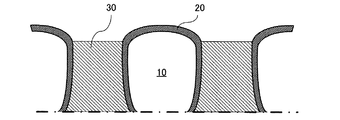
以下、撥水層の溶解について、図面を参照して説明する。図1〜6はいずれも、ノズルプレートの断面図である。なお、メニスカスの形状は図に表していない。
図1は、多数の分子が重合して形成された樹脂膜からなる撥水層20が、ノズル内部まで形成されているノズルプレート10に、撥水層溶解液30を充填した直後の状態を示す模式図である。
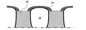
図2は、撥水層溶解液30を充填してから時間が経過し、撥水層20が溶解した状態を示す模式図である。
ノズルが十分に細い管状の構造であれば、静的には撥水層の影響よりも、毛細管現象の影響の方が強いため、ノズル孔を均一に構成すれば、充填した撥水層溶解液がメニスカスを張る位置もノズル毎に略均一になる。したがって、撥水層がノズル孔に入りこむ境界を各ノズルでおおよそ均一な位置にすることができる。
Hereinafter, dissolution of the water repellent layer will be described with reference to the drawings. 1 to 6 are sectional views of the nozzle plate. The shape of the meniscus is not shown in the figure.
FIG. 1 shows a state immediately after a
FIG. 2 is a schematic view showing a state in which the water-
If the nozzle has a sufficiently thin tubular structure, the influence of the capillary phenomenon is stronger than the influence of the water-repellent layer statically. Therefore, if the nozzle holes are configured uniformly, the filled water-repellent layer solution The position where the meniscus is stretched is also substantially uniform for each nozzle. Therefore, the boundary where the water repellent layer enters the nozzle hole can be set to a substantially uniform position for each nozzle.
図2のように、ノズルのノズル孔表面に対して鉛直な内壁部位に付着した撥水層は、プラズマ照射では十分に除去できないが、液体である撥水層溶解液に浸漬できるため、除去が可能である。また本発明では超音波の衝撃等で物理的に撥水剤を剥がし取った場合と異なり、撥水層を溶解させることから、剥がれた撥水層を固形物として残存させることなく、ノズル孔から液体として除去が可能である。 As shown in FIG. 2, the water repellent layer adhering to the inner wall portion perpendicular to the nozzle hole surface of the nozzle cannot be removed sufficiently by plasma irradiation, but can be removed because it can be immersed in the liquid water repellent layer solution. Is possible. Further, in the present invention, unlike the case where the water repellent is physically peeled off by an ultrasonic impact or the like, the water repellent layer is dissolved, so that the peeled water repellent layer does not remain as a solid substance and is left from the nozzle hole. It can be removed as a liquid.
一方、図3は、多数の分子が重合して形成された樹脂膜からなる撥水層20が撥水層溶解液30に長時間浸漬されたとき、ノズルプレート10から撥水層20が剥離し、隙間に撥水層溶解液30が毛細管現象で入り込んだ状態を表した模式図である。このように、過度に長期間にわたり撥水層溶解液30を充填していると、重合により巨大分子となる樹脂膜からなる撥水層20は、液体の界面において溶解によって基材と撥水層との間に隙間が生じ、この隙間に毛管現象で撥水層溶解液30が染込むことになり、撥水層と基材との界面から撥水層が剥がれて浮いてしまい、図4に示すように、ワイピングなどにより削り取られてしまうことがある。
On the other hand, FIG. 3 shows that when the
この現象を回避するために、撥水層20を形成する樹脂膜は、単分子からなる単分子膜であることが好ましい。
図5は、単分子膜から成る撥水層21がノズル内壁に形成されたノズルプレート10に撥水層溶解液30を充填し、メニスカス31が形成された直後の状態を示した図である。
界面において撥水層溶解液30に触れた撥水層21は溶解してしまうが、単分子であるため、分子間の水平方向にのびる結合が無く、ノズルプレート10と撥水層21との間には、図3に示したような隙間は生じない。この様子を図6に示す。
したがって、長期間、撥水層溶解液30を充填した状態を維持しても、ノズル孔のエッジ部における撥水層21の耐久性は低下しない。
In order to avoid this phenomenon, the resin film forming the
FIG. 5 is a view showing a state immediately after the water
The water-
Therefore, even if the state in which the water
撥水層溶解液は、インクジェット記録装置に適用される場合は、記録液であるインクよりもpHが大きな弱アルカリ性が好ましく、具体的にはpH9.5〜11であることが好ましい。pHが11を超えても、9.5未満であっても、液室の金属を溶解することがあるため好ましくない。 When applied to an ink jet recording apparatus, the water repellent layer solution is preferably weakly alkaline with a pH higher than that of the ink that is the recording liquid, and more preferably pH 9.5 to 11. Even if the pH exceeds 11 or less than 9.5, the metal in the liquid chamber may be dissolved, which is not preferable.
なお、撥水層溶解液は、溶媒として水を含有するが、その他の成分として、更に水溶性有機溶剤及びその他の添加剤を含んでいてもよい。
水溶性有機溶剤としては、例えば、ジメチルホルムアミド、ジメチルアセトアミド等のアミド類、アセトン等のケトン類、テトラヒドロフラン、ジオキサン等のエーテル類、ポリエチレングリコール、ポリプロピレングリコール等のポリアルキレングリコール類、エチレングリコール、プロピレングリコール、ブチレングリコール、トリエチレングリコール、1,2,6−ヘキサントリオール、チオジグリコール、ヘキシレングリコール、ジエチレングリコール等のアルキレングリコール類、エチレングリコールメチルエーテル、ジエチレングリコールモノメチルエーテル、トリエチレングリコールモノメチルエーテル等の多価アルコールの低級アルキルエーテル類、エタノール、イソプロピルアルコール、n−ブチルアルコール、イソブチルアルコール等の1価アルコール類の他、グリセリン、N−メチル−2−ピロリドン、1,3−ジメチル−イミダゾリジノン、トリエタノールアミン、スルホラン、ジメチルサルホキサイド等が挙げられる。上記水溶性有機溶剤の含有量については特に制限はないが、例えば、全質量の5〜60%、更には5〜40%が好適な範囲である。
The water repellent layer solution contains water as a solvent, but may further contain a water-soluble organic solvent and other additives as other components.
Examples of water-soluble organic solvents include amides such as dimethylformamide and dimethylacetamide, ketones such as acetone, ethers such as tetrahydrofuran and dioxane, polyalkylene glycols such as polyethylene glycol and polypropylene glycol, ethylene glycol, and propylene glycol. , Alkylene glycols such as butylene glycol, triethylene glycol, 1,2,6-hexanetriol, thiodiglycol, hexylene glycol, diethylene glycol, polyvalent such as ethylene glycol methyl ether, diethylene glycol monomethyl ether, triethylene glycol monomethyl ether Lower alkyl ethers of alcohol, ethanol, isopropyl alcohol, n-butyl alcohol, isobuty Other monohydric alcohols such as alcohols, glycerin, N- methyl-2-pyrrolidone, 1,3-dimethyl - imidazolidinone, triethanolamine, sulfolane, dimethyl monkey Hoki side, and the like. Although there is no restriction | limiting in particular about content of the said water-soluble organic solvent, For example, 5 to 60% of the total mass, Furthermore, 5 to 40% is a suitable range.
本発明の液体吐出ヘッドの製造方法においては、メニスカス位置が各ノズルにおいてより均一に形成されるように、撥水層溶解液に界面活性剤を添加して、撥水層溶解液の表面張力を十分に下げることにより、充填後に形成されるメニスカス位置のバラツキを抑えることができる。
撥水層溶解液の表面張力を低くすることにより、毛細管現象の影響が強まり、メニスカスを形成する位置が、ノズル開口部からノズル内径が最も小さい位置に一様に定められる。
In the method for manufacturing a liquid discharge head of the present invention, a surface active agent is added to the water repellent layer solution so that the meniscus position is more uniformly formed in each nozzle, and the surface tension of the water repellent layer solution is increased. By sufficiently lowering, variation in meniscus position formed after filling can be suppressed.
By reducing the surface tension of the water repellent layer solution, the influence of capillary action is strengthened, and the position where the meniscus is formed is uniformly determined from the nozzle opening to the position where the nozzle inner diameter is the smallest.
撥水層溶解液に添加される界面活性剤としては、ノニオン性界面活性剤、又はアニオン性界面活性剤が好ましい。
低分子量のアニオン性界面活性剤としては、例えば、スルホコハク酸ラウリル二ナトリウム、スルホコハク酸ポリオキシエチレンラウロイルエタノールアミドエステル二ナトリウム、ポリオキシエチレンアルキルスルホコハク酸二ナトリウム、カルボキシル化ポリオキシエチレンラウリルエーテルナトリウム塩、カルボキシル化ポリオキシエチレントリデシルエーテルナトリウム塩、ポリオキシエチレンラウリルエーテル硫酸ナトリウム、ポリオキシエチレンラウリルエーテル硫酸トリエタノールアミン、ポリオキシエチレンアルキルエーテル硫酸ナトリウム、アルキル硫酸ナトリウム、アルキル硫酸トリエタノールアミン等が挙げられるが、これらに限定されるわけではない。
以上のようなアニオン性物質の好適な使用量としては、全量に対して、0.05〜10質量%の範囲であり、更に好適には0.05〜5質量%である。
As the surfactant added to the water repellent layer solution, a nonionic surfactant or an anionic surfactant is preferable.
Examples of low molecular weight anionic surfactants include disodium lauryl sulfosuccinate, disodium polyoxyethylene lauroyl ethanolamide ester sulfosuccinate, disodium polyoxyethylene alkylsulfosuccinate, carboxylated polyoxyethylene lauryl ether sodium salt, Carboxylated polyoxyethylene tridecyl ether sodium salt, sodium polyoxyethylene lauryl ether sulfate, polyoxyethylene lauryl ether sulfate triethanolamine, polyoxyethylene alkyl ether sodium sulfate, sodium alkyl sulfate, alkyl sulfate triethanolamine, etc. However, it is not limited to these.
A suitable amount of the anionic substance as described above is in the range of 0.05 to 10% by mass, more preferably 0.05 to 5% by mass, based on the total amount.
また、撥水層溶解液には、上記の成分の他に、pH調整剤、防腐剤、防カビ剤、消泡剤等が添加されても良い。 In addition to the above components, a pH adjuster, an antiseptic, an antifungal agent, an antifoaming agent, and the like may be added to the water repellent layer solution.
本発明の液体吐出ヘッド、及び前記液体吐出ヘッドを搭載した画像記録装置は、撥水層溶解液をヘッドに充填した状態で出荷を行う。
本発明の液体吐出ヘッド及び該液体吐出搭載した画像記録装置を、撥水層溶解液をヘッドに充填した状態で出荷を行う出荷方法により出荷されることが好ましい。
ノズル内部の撥水層の溶解には時間がかかるが、溶解完了まで出荷を止めていては在庫が過多になるという問題を生じる。これに対し、上記のような出荷方法によれば、ヘッド出荷から初期充填までの時間を有効に使うことができる。
The liquid discharge head of the present invention and the image recording apparatus equipped with the liquid discharge head are shipped in a state where the water repellent layer solution is filled in the head.
The liquid discharge head of the present invention and the image recording apparatus mounted with the liquid discharge are preferably shipped by a shipping method in which the head is filled with a water-repellent layer solution.
Although it takes time to dissolve the water-repellent layer inside the nozzle, there is a problem that the inventory becomes excessive if the shipment is stopped until the dissolution is completed. On the other hand, according to the shipping method as described above, the time from head shipment to initial filling can be used effectively.
次に、本発明に係る液体吐出ヘッドを備える画像形成装置の一実施の形態について図7を参照して以下に説明する。図7は、本発明の画像形成装置の機構部の全体構成を説明する概略構成図である。 Next, an embodiment of an image forming apparatus including a liquid ejection head according to the present invention will be described below with reference to FIG. FIG. 7 is a schematic configuration diagram illustrating the overall configuration of the mechanism unit of the image forming apparatus of the present invention.
この画像形成装置はシリアル型画像形成装置であり、左右の側板に横架したガイド部材である主従のガイドロッド91、92でキャリッジ93を主走査方向に摺動自在に保持し、図示しない主走査モータによってタイミングベルトを介して矢示方向(キャリッジ主走査方向)に移動走査する。
This image forming apparatus is a serial type image forming apparatus, and a
このキャリッジ93には、イエロー(Y)、シアン(C)、マゼンタ(M)、ブラック(K)の各色のインク滴を吐出するための本発明に係る液体吐出ヘッドからなる記録ヘッド94を複数のノズルからなるノズル列を主走査方向と直交する副走査方向に配列し、インク滴吐出方向を下方に向けて装着している。
The
また、キャリッジ93には、記録ヘッド94のノズル列に対応して各色のインクを供給するためのヘッドタンク95を搭載している。
The
一方、給紙トレイの用紙積載部(圧板)83上に積載した用紙を給紙するための給紙部として、用紙積載部83から用紙を1枚ずつ分離給送する給紙コロ101、及び給紙コロ101に対向し、摩擦係数の大きな材質からなる分離パッド102を備え、この分離パッドは給紙コロ側に付勢されている。
On the other hand, as a sheet feeding unit for feeding sheets stacked on the sheet stacking unit (pressure plate) 83 of the sheet feeding tray, a
そして、この給紙部から給紙された用紙を記録ヘッド94の下方側に送り込むために、用紙を案内するガイド部材103と、カウンタローラ、搬送ガイド部材、先端加圧コロを有する押さえ部材とを備えるとともに、給送された用紙を静電吸着して記録ヘッド94に対向する位置で搬送するための搬送手段である搬送ベルトを備えている。
In order to feed the paper fed from the paper feeding unit to the lower side of the
さらに、キャリッジ93の走査方向一方側の非印字領域には、記録ヘッド94のノズルの状態を維持し、回復するための回復手段を含む維持回復機構(図示せず)を配置している。この維持回復機構には、記録ヘッド94の各ノズル面をキャピングするための各キャップ部材と、ノズル面をワイピングするためのブレード部材であるワイパーブレードと、増粘した記録液を排出するために記録に寄与しない液滴を吐出させる空吐出を行うときの液滴を受ける空吐出受けなどを備えている。
Further, a maintenance / recovery mechanism (not shown) including a recovery means for maintaining and recovering the state of the nozzles of the
また、キャリッジ93の走査方向他方側の非印字領域には、記録中などに増粘した記録液を排出するために記録に寄与しない液滴を吐出させる空吐出を行うときの液滴を受ける液体回収容器であるインク回収ユニット(空吐出受け)を配置し、このインク回収ユニットには記録ヘッド94のノズル列方向に沿った開口部などを備えている。
Further, in the non-printing area on the other side of the
キャリッジ93を移動させながら画像信号に応じて記録ヘッド94を駆動することにより、停止している用紙にインク滴を吐出して1行分を記録し、用紙を所定量搬送後、次の行の記録を行う。記録終了信号又は用紙の後端が記録領域に到達した信号を受けることにより、記録動作を終了して、用紙を排紙トレイ86に排紙する。
By driving the
このようなシリアル型画像形成装置において、本発明に係る液体吐出ヘッドを備えることによって、吐出される液体の着弾位置に乱れを生じさせることなく、安定した滴吐出特性が得られるので、高速で高画質画像を記録できるようになる。 In such a serial type image forming apparatus, by providing the liquid discharge head according to the present invention, stable droplet discharge characteristics can be obtained without causing disturbance in the landing position of the discharged liquid. It becomes possible to record image quality images.
以下、本発明の実施例を説明する。
以下の方法により、液体吐出ヘッドのノズルプレートA及びBを作製した。
1)ノズルプレートAの作製
Niノズルプレートに対し、高分子撥水剤(X-40-9250(10%)+KR-400(90%)、信越シリコーン株式会社製)を、ノズルプレートのノズル孔が開口する液体吐出側の表面にスピンコートした後、ノズルプレートの液室面側からO2プラズマを照射して、ノズル孔からノズル内面のノズルプレート液室面側に入り込んで形成された撥水層を除去した。
ノズル孔のノズル開口端部近傍は、液体吐出側の表面に対してほぼ垂直となっており、このほぼ垂直になっている領域のノズル内面の撥水層の除去の程度は各ノズル間でバラツキが見られた。
Examples of the present invention will be described below.
The nozzle plates A and B of the liquid discharge head were produced by the following method.
1) Preparation of nozzle plate A A polymer water repellent (X-40-9250 (10%) + KR-400 (90%), manufactured by Shin-Etsu Silicone Co., Ltd.) is applied to the Ni nozzle plate with nozzle holes in the nozzle plate. The water repellent formed by spin-coating the liquid discharge side surface of the nozzle opening and then irradiating O 2 plasma from the liquid chamber surface side of the nozzle plate and entering the nozzle plate liquid chamber surface side of the nozzle inner surface from the nozzle hole The layer was removed.
The vicinity of the nozzle opening end of the nozzle hole is substantially perpendicular to the surface on the liquid discharge side, and the degree of removal of the water-repellent layer on the inner surface of the nozzle in this substantially perpendicular region varies between nozzles. It was observed.
2)ノズルプレートBの作製
Niノズルプレートに対し、単分子のフッ素樹脂撥水剤(オプツールDSX 、ダイキン工業株式会社製)をノズルプレートのノズル孔が開口する液体吐出側の表面に真空蒸着した後、ノズルプレートの液室面側からO2プラズマを照射して、ノズル孔からノズル内面のノズルプレート液室面側に入り込んで形成された単分子膜の樹脂膜からなる撥水層を除去した。
ノズル孔のノズル開口端部近傍は、液体吐出側の表面に対してほぼ垂直となっており、このほぼ垂直になっている領域のノズル内面の撥水層の除去の程度は各ノズル間でバラツキが見られた。
2) Preparation of nozzle plate B After vacuum-depositing a monomolecular fluororesin water repellent (OPTOOL DSX, manufactured by Daikin Industries, Ltd.) on the surface of the liquid ejection side where the nozzle holes of the nozzle plate are opened. Then, O 2 plasma was irradiated from the liquid chamber surface side of the nozzle plate to remove the water-repellent layer made of a monomolecular resin film formed by entering the nozzle plate liquid chamber surface side of the nozzle inner surface from the nozzle hole.
The vicinity of the nozzle opening end of the nozzle hole is substantially perpendicular to the surface on the liquid discharge side, and the degree of removal of the water-repellent layer on the inner surface of the nozzle in this substantially perpendicular region varies between nozzles. It was observed.
(実施例1)
上記ノズルプレートAを用いて液体吐出ヘッドを作製した。
作製された液体吐出ヘッドに、下記に示す組成からなる撥水層溶解液Aを充填し、ノズル内にメニスカスを形成させた。50℃の環境下で3週間置いた後、図7に示す画像記録装置(IPSIO G707改造機、リコー製)に搭載し、インクを充填して150dpiピッチの網点からなる印刷物を作成した。作成された印刷物から、インクの着弾位置バラツキを評価した。結果を表1に示す。
Example 1
A liquid discharge head was manufactured using the nozzle plate A.
The prepared liquid discharge head was filled with a water repellent layer solution A having the composition shown below to form a meniscus in the nozzle. After 3 weeks in an environment of 50 ° C., it was mounted on an image recording apparatus (IPSIO G707 modified machine, manufactured by Ricoh) shown in FIG. 7 and filled with ink to produce a printed matter consisting of a halftone dot of 150 dpi pitch. The ink landing position variation was evaluated from the prepared printed matter. The results are shown in Table 1.
<撥水層溶解液Aの組成>
グリセリン 25部
2−ピロリドン 2部
デヒドロ酢酸ナトリウム 0.2部
チオ硫酸ナトリウム 0.2部
防腐防黴剤 0.4部
消泡剤(信越化学社製、KM−72F) 0.1部
イオン交換水 残量
上記組成に対し、さらにpH調整剤を加え、pH11.0に調整して用いた。
<Composition of water repellent layer solution A>
Glycerin 25 parts 2-pyrrolidone 2 parts sodium dehydroacetate 0.2 parts sodium thiosulfate 0.2 parts antiseptic / antifungal agent 0.4 parts antifoaming agent (manufactured by Shin-Etsu Chemical Co., Ltd., KM-72F) 0.1 part ion-exchanged water Residual amount To the above composition, a pH adjusting agent was further added to adjust the pH to 11.0.
(実施例2)
上記ノズルプレートBを用いて液体吐出ヘッドを作製した以外は、実施例1と同様にして撥水層溶解液Aを充填し、50℃の環境下で3週間置いた後、図7に示す画像記録装置 (IPSIO G707改造機、リコー製)に搭載し、インクを充填して150dpiピッチの網点からなる印刷物を作成した。作成された印刷物から、インクの着弾位置バラツキを評価した。また、撥水層溶解液充填直後に、メニスカス形成位置を観察した。結果をあわせて表1に示す。
(Example 2)
Except that a liquid discharge head was produced using the nozzle plate B, the water repellent layer solution A was filled in the same manner as in Example 1 and left at 50 ° C. for 3 weeks. It was mounted on a recording device (IPSIO G707 modified machine, manufactured by Ricoh Co., Ltd.) and filled with ink to produce a printed matter consisting of halftone dots of 150 dpi pitch. The ink landing position variation was evaluated from the prepared printed matter. In addition, the meniscus formation position was observed immediately after filling the water-repellent layer solution. The results are shown in Table 1.
(実施例3)
上記ノズルプレートBを用いて液体吐出ヘッドを作製した。
作製された液体吐出ヘッドに、下記に示す組成からなる撥水層溶解液Bを充填し、ノズル内にメニスカスを形成させた。50℃の環境下で3週間置いた後、図7に示す画像記録装置 (IPSIO G707改造機、リコー製)に搭載し、インクを充填して150dpiピッチの網点からなる印刷物を作成した。作成された印刷物から、インクの着弾位置バラツキを評価した。また、撥水層溶解液充填直後に、メニスカス形成位置を観察した。結果をあわせて表1に示す。
(Example 3)
A liquid discharge head was manufactured using the nozzle plate B.
The prepared liquid discharge head was filled with a water-repellent layer solution B having the following composition to form a meniscus in the nozzle. After 3 weeks in an environment of 50 ° C., it was mounted on an image recording apparatus (IPSIO G707 modified machine, manufactured by Ricoh) shown in FIG. 7 and filled with ink to create a printed matter consisting of halftone dots of 150 dpi pitch. The ink landing position variation was evaluated from the prepared printed matter. In addition, the meniscus formation position was observed immediately after filling the water-repellent layer solution. The results are shown in Table 1.
<撥水層溶解液Bの組成>
グリセリン 25部
2−ピロリドン 2部
オレフィンSTG(信越化学製) 2.0部
デヒドロ酢酸ナトリウム 0.2部
チオ硫酸ナトリウム 0.2部
防腐防黴剤 0.4部
消泡剤(信越化学社製、KM−72F) 0.1部
イオン交換水 残量
上記組成に対し、さらにpH調整剤を加え、pH11.0に調整して用いた。
<Composition of water repellent layer solution B>
Glycerin 25 parts 2-Pyrrolidone 2 parts Olefin STG (manufactured by Shin-Etsu Chemical) 2.0 parts Sodium dehydroacetate 0.2 part Sodium thiosulfate 0.2 part Antiseptic / antifungal agent 0.4 part Antifoam (manufactured by Shin-Etsu Chemical Co., Ltd., KM-72F) 0.1 parts Ion-exchanged water Remaining The composition was further adjusted to pH 11.0 by adding a pH adjuster.
(比較例1)
上記ノズルプレートAを用いて液体吐出ヘッドを作製した。作製された液体吐出ヘッドを50℃の環境下で3週間置いた後、図7に示す画像記録装置 (IPSIO G707改造機、リコー製)に搭載し、インクを充填して150dpiピッチの網点からなる印刷物を作成した。作成された印刷物から、インクの着弾位置バラツキを評価した。結果を表1に示す。
(Comparative Example 1)
A liquid discharge head was manufactured using the nozzle plate A. After the prepared liquid discharge head is placed in a 50 ° C. environment for 3 weeks, it is mounted on the image recording apparatus (IPSIO G707 remodeling machine, manufactured by Ricoh) shown in FIG. 7 and filled with ink from a halftone dot of 150 dpi pitch. I made a printed material. The ink landing position variation was evaluated from the prepared printed matter. The results are shown in Table 1.
(比較例2)
上記ノズルプレートBを用いて液体吐出ヘッドを作製した。作製された液体吐出ヘッドを50℃の環境下で3週間置いた後、図7に示す画像記録装置 (IPSIO G707改造機、リコー製)に搭載し、インクを充填して150dpiピッチの網点からなる印刷物を作成した。作成された印刷物から、インクの着弾位置バラツキを評価した。結果を表1に示す。
(Comparative Example 2)
A liquid discharge head was manufactured using the nozzle plate B. After the prepared liquid discharge head is placed in a 50 ° C. environment for 3 weeks, it is mounted on the image recording apparatus (IPSIO G707 remodeling machine, manufactured by Ricoh) shown in FIG. 7 and filled with ink from a halftone dot of 150 dpi pitch. I made a printed material. The ink landing position variation was evaluated from the prepared printed matter. The results are shown in Table 1.

インクの着弾位置バラツキは、印刷物を観察し、下記の基準に従って評価した。
◎:白スジ、黒スジはみられず、インクは規則正しいピッチで印字されている。
〇:やや、インク着弾位置に乱れは見られるものの、普通紙の印刷では白スジ、黒スジはさほど目立たない。
△:着弾位置に乱れが見られ、印字で白スジ、黒スジを生じるノズル孔がある。
×:殆どのノズル孔から吐出されたインクに着弾位置の乱れがある。白スジ、黒スジが非常に多い。
The ink landing position variation was evaluated according to the following criteria by observing the printed matter.
A: White stripes and black stripes are not observed, and ink is printed at a regular pitch.
A: Slightly disturbed ink landing position, but white and black streaks are not so noticeable when printing on plain paper.
(Triangle | delta): Disturbance is seen in a landing position and there exists a nozzle hole which produces a white stripe and a black stripe by printing.
X: The ink ejected from most of the nozzle holes has a disordered landing position. There are very many white and black stripes.
表1の結果から、撥水層溶解液を充填した実施例の液体吐出ヘッドは、充填しない比較例のヘッドよりもインク着弾位置のバラツキが小さいことがわかった。また、実施例2及び3を比較すると、界面活性剤(オレフィンSTG(信越化学製))を加えて表面張力を小さくした撥水層溶解液Bでノズル内部を浸漬した実施例3は、インク着弾位置バラツキが極めて小さいことがわかった。
一方、実施例2及び3について、撥水層溶解液をそれぞれ充填した状態のヘッドの観察を行った結果、実施例2のヘッドでは、ノズル間でメニスカスの形成された位置に若干バラツキがみられたのに対して、実施例3のヘッドには、メニスカスの形成される位置が均一であった。このことから、撥水層溶解液の濡れ性を高くすることで、ノズル内部に入り込んで形成された撥水層の影響を受けることなく、充填された溶液のメニスカスの形成位置がばらつくことを抑え、ノズルプレートの形状に依存して各ノズル間で均一な位置にメニスカス位置が定まったと考えられる。
From the results shown in Table 1, it was found that the liquid ejection head of the example filled with the water repellent layer solution had a smaller variation in ink landing position than the head of the comparative example without filling. In addition, when Examples 2 and 3 are compared, Example 3 in which the inside of the nozzle is immersed in a water-repellent layer solution B having a surface tension reduced by adding a surfactant (olefin STG (manufactured by Shin-Etsu Chemical)) is ink landing. It was found that the position variation was extremely small.
On the other hand, as a result of observing the heads filled with the water-repellent layer solution for Examples 2 and 3, the heads of Example 2 showed slight variations in the positions where meniscuses were formed between the nozzles. On the other hand, in the head of Example 3, the position where the meniscus was formed was uniform. For this reason, by increasing the wettability of the water-repellent layer solution, it is possible to suppress variations in the meniscus formation position of the filled solution without being affected by the water-repellent layer formed inside the nozzle. It is considered that the meniscus position is determined at a uniform position between the nozzles depending on the shape of the nozzle plate.
(実施例4)
実施例1の画像記録装置において、搭載した液体吐出ヘッドのノズル孔が開口する液体吐出側の表面に対し、ワイピングを1000回行った。その後、再度インクを充填して150dpiピッチの網点からなる印刷物を作成した。作成された印刷物から、上記と同様の基準でインクの着弾位置バラツキを評価した。結果を表2に示す。
Example 4
In the image recording apparatus of Example 1, wiping was performed 1000 times on the surface on the liquid discharge side where the nozzle hole of the mounted liquid discharge head was opened. After that, the ink was filled again, and a printed matter having a halftone dot of 150 dpi pitch was created. The ink landing position variation was evaluated from the prepared printed matter according to the same criteria as described above. The results are shown in Table 2.
(実施例5)
実施例2の画像形成装置において、実施例4と同様にしてワイピングを行い、印刷物を作成した。作成された印刷物から、上記と同様の基準でインクの着弾位置バラツキを評価した。結果を表2に示す。
(Example 5)
In the image forming apparatus of Example 2, wiping was performed in the same manner as in Example 4 to produce a printed matter. The ink landing position variation was evaluated from the prepared printed matter according to the same criteria as described above. The results are shown in Table 2.
(実施例6)
実施例3の画像形成装置において、実施例4と同様にしてワイピングを行い、印刷物を作成した。作成された印刷物から、上記と同様の基準でインクの着弾位置バラツキを評価した。結果を表2に示す。
(Example 6)
In the image forming apparatus of Example 3, wiping was performed in the same manner as in Example 4 to produce a printed matter. The ink landing position variation was evaluated from the prepared printed matter according to the same criteria as described above. The results are shown in Table 2.
表2の結果から、1000回のワイピング後、多数の分子が重合した高分子樹脂膜からなる撥水層を有する実施例4では、着弾位置バラツキが大きくなったのに対し、単分子膜の撥水層を有する実施例5及び6では、ワイピングする前(それぞれ実施例2及び4)と同様に良好であった。
実施例4の液体吐出ヘッドのノズルエッジを観察すると、ノズル孔のワイピング方向下手側で、撥インク性が低下してインクが付着し易く成っている部位があり、ノズル近傍の撥水層が剥がれて消失している部位もあることが観察された。このことから、撥水層は、単分子の樹脂からなる単分子膜により形成されることが好ましいことが明らかになった。
From the results in Table 2, in Example 4 having a water-repellent layer composed of a polymer resin film in which a large number of molecules are polymerized after 1000 times of wiping, the landing position variation was large, whereas the repellent property of the monomolecular film was large. Examples 5 and 6 having an aqueous layer were as good as before wiping (Examples 2 and 4 respectively).
When the nozzle edge of the liquid ejection head of Example 4 is observed, there is a portion where the ink repellency is lowered and the ink is easily attached on the lower side of the wiping direction of the nozzle hole, and the water repellent layer near the nozzle is peeled off. It was observed that some sites disappeared. From this, it became clear that the water repellent layer is preferably formed of a monomolecular film made of a monomolecular resin.
なお、これまで本発明を図面に示した実施形態をもって説明してきたが、本発明は図面に示した実施形態に限定されるものではなく、他の実施形態、追加、変更、削除など、当業者が想到することができる範囲内で変更することができ、いずれの態様においても本発明の作用・効果を奏する限り、本発明の範囲に含まれるものである。 Although the present invention has been described with the embodiments shown in the drawings, the present invention is not limited to the embodiments shown in the drawings, and other embodiments, additions, modifications, deletions, etc. Can be changed within the range that can be conceived, and any embodiment is included in the scope of the present invention as long as the effects and advantages of the present invention are exhibited.
10 ノズルプレート
20 撥水層(多数の分子が重合して形成された樹脂膜からなる撥水層)
21 撥水層(単分子膜からなる撥水層)
30 撥水層溶解液
31 メニスカス
94 記録ヘッド
10
21 Water repellent layer (water repellent layer composed of monomolecular film)
30 Water
Claims (6)
前記ノズルプレート表面に前記樹脂膜からなる撥水層を形成する工程と、
前記ノズルプレートを液体吐出ヘッドに組み込む工程と、
前記ノズル内に撥水層溶解液のメニスカスを形成するように前記液体吐出ヘッド内に撥水層溶解液を充填する工程と、を有することを特徴とする液体吐出ヘッドの製造方法。 In a method for manufacturing a liquid discharge head, comprising a nozzle plate having a nozzle for discharging a liquid and having a water repellent layer made of a resin film formed on a surface on a liquid discharge side where a nozzle hole opens.
Forming a water repellent layer made of the resin film on the nozzle plate surface;
Incorporating the nozzle plate into the liquid ejection head;
And a step of filling the liquid discharge head with the water-repellent layer solution so as to form a meniscus of the water-repellent layer solution in the nozzle.
Priority Applications (1)
| Application Number | Priority Date | Filing Date | Title |
|---|---|---|---|
| JP2008210974A JP5228693B2 (en) | 2008-08-19 | 2008-08-19 | Method for manufacturing liquid discharge head, liquid discharge head, and image forming apparatus |
Applications Claiming Priority (1)
| Application Number | Priority Date | Filing Date | Title |
|---|---|---|---|
| JP2008210974A JP5228693B2 (en) | 2008-08-19 | 2008-08-19 | Method for manufacturing liquid discharge head, liquid discharge head, and image forming apparatus |
Publications (2)
| Publication Number | Publication Date |
|---|---|
| JP2010046824A true JP2010046824A (en) | 2010-03-04 |
| JP5228693B2 JP5228693B2 (en) | 2013-07-03 |
Family
ID=42064347
Family Applications (1)
| Application Number | Title | Priority Date | Filing Date |
|---|---|---|---|
| JP2008210974A Expired - Fee Related JP5228693B2 (en) | 2008-08-19 | 2008-08-19 | Method for manufacturing liquid discharge head, liquid discharge head, and image forming apparatus |
Country Status (1)
| Country | Link |
|---|---|
| JP (1) | JP5228693B2 (en) |
Citations (3)
| Publication number | Priority date | Publication date | Assignee | Title |
|---|---|---|---|---|
| JP2000127442A (en) * | 1998-10-27 | 2000-05-09 | Canon Inc | Recording head and method for preserving recording head |
| JP2007216664A (en) * | 2005-10-20 | 2007-08-30 | Ricoh Co Ltd | Recording ink, recording media, ink media set, ink recorded article, inkjet recording method, and inkjet recording device |
| JP2007253479A (en) * | 2006-03-23 | 2007-10-04 | Fujifilm Corp | Nozzle plate manufacturing method, liquid droplet discharge head, and image forming apparatus |
-
2008
- 2008-08-19 JP JP2008210974A patent/JP5228693B2/en not_active Expired - Fee Related
Patent Citations (3)
| Publication number | Priority date | Publication date | Assignee | Title |
|---|---|---|---|---|
| JP2000127442A (en) * | 1998-10-27 | 2000-05-09 | Canon Inc | Recording head and method for preserving recording head |
| JP2007216664A (en) * | 2005-10-20 | 2007-08-30 | Ricoh Co Ltd | Recording ink, recording media, ink media set, ink recorded article, inkjet recording method, and inkjet recording device |
| JP2007253479A (en) * | 2006-03-23 | 2007-10-04 | Fujifilm Corp | Nozzle plate manufacturing method, liquid droplet discharge head, and image forming apparatus |
Also Published As
| Publication number | Publication date |
|---|---|
| JP5228693B2 (en) | 2013-07-03 |
Similar Documents
| Publication | Publication Date | Title |
|---|---|---|
| JP5347687B2 (en) | Image forming apparatus | |
| JP2008012826A (en) | Head cleaning device of inkjet printer and inkjet printer | |
| JP2006212870A (en) | Inkjet recorder | |
| JP2016124111A (en) | Inkjet recording device | |
| JP5028864B2 (en) | Inkjet recording device | |
| JP5228693B2 (en) | Method for manufacturing liquid discharge head, liquid discharge head, and image forming apparatus | |
| CN108297548B (en) | Recording head and ink jet recording apparatus provided with the same | |
| JP2006341392A (en) | Liquid droplet jet device and method for cleaning wiping member | |
| JP2011201287A (en) | Inkjet head assembly | |
| JP2006240235A (en) | Ink jet head cleaning device and ink jet recording apparatus | |
| JPH11334069A (en) | Ink jet head | |
| JP2011025476A (en) | Inkjet recorder and recovery method for liquid droplet ejection means | |
| CN108583012B (en) | Head cleaning mechanism and inkjet recording apparatus including the same | |
| JP6589891B2 (en) | Head cleaning mechanism and ink jet recording apparatus having the same | |
| JP5402440B2 (en) | Image forming apparatus and processing liquid coating apparatus | |
| JP2012240274A (en) | Liquid droplet ejection head cleaning device, liquid droplet ejection head, and image forming apparatus | |
| JP6589893B2 (en) | Head cleaning mechanism and ink jet recording apparatus having the same | |
| JP2007050608A (en) | Inkjet head recovering device, and cleaning method for inkjet head | |
| JP2015180536A (en) | Liquid ejection and recording device and liquid recovery method | |
| JP2019018355A (en) | Recording head and inkjet recording device including the same | |
| JP5304561B2 (en) | Image forming apparatus and processing liquid coating apparatus | |
| JP2014024258A (en) | Inkjet recording device | |
| JP6690558B2 (en) | Recording head and ink jet recording apparatus including the same | |
| JP2006168077A (en) | Maintenance method for image-forming apparatus | |
| JP2001146018A (en) | Ink-jet recording device, method for discharging ink from capping means of the device, and ink composition used in the device |
Legal Events
| Date | Code | Title | Description |
|---|---|---|---|
| A621 | Written request for application examination |
Free format text: JAPANESE INTERMEDIATE CODE: A621 Effective date: 20110613 |
|
| A977 | Report on retrieval |
Free format text: JAPANESE INTERMEDIATE CODE: A971007 Effective date: 20121121 |
|
| A131 | Notification of reasons for refusal |
Free format text: JAPANESE INTERMEDIATE CODE: A131 Effective date: 20121204 |
|
| A521 | Request for written amendment filed |
Free format text: JAPANESE INTERMEDIATE CODE: A523 Effective date: 20130125 |
|
| TRDD | Decision of grant or rejection written | ||
| A01 | Written decision to grant a patent or to grant a registration (utility model) |
Free format text: JAPANESE INTERMEDIATE CODE: A01 Effective date: 20130219 |
|
| A61 | First payment of annual fees (during grant procedure) |
Free format text: JAPANESE INTERMEDIATE CODE: A61 Effective date: 20130304 |
|
| FPAY | Renewal fee payment (event date is renewal date of database) |
Free format text: PAYMENT UNTIL: 20160329 Year of fee payment: 3 |
|
| R151 | Written notification of patent or utility model registration |
Ref document number: 5228693 Country of ref document: JP Free format text: JAPANESE INTERMEDIATE CODE: R151 |
|
| LAPS | Cancellation because of no payment of annual fees |