JP2010046215A - Biological information imaging apparatus and biological information imaging method - Google Patents
Biological information imaging apparatus and biological information imaging method Download PDFInfo
- Publication number
- JP2010046215A JP2010046215A JP2008211993A JP2008211993A JP2010046215A JP 2010046215 A JP2010046215 A JP 2010046215A JP 2008211993 A JP2008211993 A JP 2008211993A JP 2008211993 A JP2008211993 A JP 2008211993A JP 2010046215 A JP2010046215 A JP 2010046215A
- Authority
- JP
- Japan
- Prior art keywords
- information
- measurement
- image
- light
- acoustic wave
- Prior art date
- Legal status (The legal status is an assumption and is not a legal conclusion. Google has not performed a legal analysis and makes no representation as to the accuracy of the status listed.)
- Granted
Links
Images


Classifications
-
- A—HUMAN NECESSITIES
- A61—MEDICAL OR VETERINARY SCIENCE; HYGIENE
- A61B—DIAGNOSIS; SURGERY; IDENTIFICATION
- A61B5/00—Measuring for diagnostic purposes; Identification of persons
- A61B5/0093—Detecting, measuring or recording by applying one single type of energy and measuring its conversion into another type of energy
- A61B5/0095—Detecting, measuring or recording by applying one single type of energy and measuring its conversion into another type of energy by applying light and detecting acoustic waves, i.e. photoacoustic measurements
-
- A—HUMAN NECESSITIES
- A61—MEDICAL OR VETERINARY SCIENCE; HYGIENE
- A61B—DIAGNOSIS; SURGERY; IDENTIFICATION
- A61B5/00—Measuring for diagnostic purposes; Identification of persons
- A61B5/0059—Measuring for diagnostic purposes; Identification of persons using light, e.g. diagnosis by transillumination, diascopy, fluorescence
- A61B5/0073—Measuring for diagnostic purposes; Identification of persons using light, e.g. diagnosis by transillumination, diascopy, fluorescence by tomography, i.e. reconstruction of 3D images from 2D projections
-
- A—HUMAN NECESSITIES
- A61—MEDICAL OR VETERINARY SCIENCE; HYGIENE
- A61B—DIAGNOSIS; SURGERY; IDENTIFICATION
- A61B5/00—Measuring for diagnostic purposes; Identification of persons
- A61B5/02—Detecting, measuring or recording pulse, heart rate, blood pressure or blood flow; Combined pulse/heart-rate/blood pressure determination; Evaluating a cardiovascular condition not otherwise provided for, e.g. using combinations of techniques provided for in this group with electrocardiography or electroauscultation; Heart catheters for measuring blood pressure
- A61B5/021—Measuring pressure in heart or blood vessels
- A61B5/02133—Measuring pressure in heart or blood vessels by using induced vibration of the blood vessel
-
- A—HUMAN NECESSITIES
- A61—MEDICAL OR VETERINARY SCIENCE; HYGIENE
- A61B—DIAGNOSIS; SURGERY; IDENTIFICATION
- A61B5/00—Measuring for diagnostic purposes; Identification of persons
- A61B5/02—Detecting, measuring or recording pulse, heart rate, blood pressure or blood flow; Combined pulse/heart-rate/blood pressure determination; Evaluating a cardiovascular condition not otherwise provided for, e.g. using combinations of techniques provided for in this group with electrocardiography or electroauscultation; Heart catheters for measuring blood pressure
- A61B5/024—Detecting, measuring or recording pulse rate or heart rate
-
- A—HUMAN NECESSITIES
- A61—MEDICAL OR VETERINARY SCIENCE; HYGIENE
- A61B—DIAGNOSIS; SURGERY; IDENTIFICATION
- A61B5/00—Measuring for diagnostic purposes; Identification of persons
- A61B5/72—Signal processing specially adapted for physiological signals or for diagnostic purposes
- A61B5/7235—Details of waveform analysis
- A61B5/7253—Details of waveform analysis characterised by using transforms
-
- A—HUMAN NECESSITIES
- A61—MEDICAL OR VETERINARY SCIENCE; HYGIENE
- A61B—DIAGNOSIS; SURGERY; IDENTIFICATION
- A61B5/00—Measuring for diagnostic purposes; Identification of persons
- A61B5/74—Details of notification to user or communication with user or patient ; user input means
- A61B5/742—Details of notification to user or communication with user or patient ; user input means using visual displays
-
- A—HUMAN NECESSITIES
- A61—MEDICAL OR VETERINARY SCIENCE; HYGIENE
- A61B—DIAGNOSIS; SURGERY; IDENTIFICATION
- A61B5/00—Measuring for diagnostic purposes; Identification of persons
- A61B5/72—Signal processing specially adapted for physiological signals or for diagnostic purposes
- A61B5/7235—Details of waveform analysis
- A61B5/7253—Details of waveform analysis characterised by using transforms
- A61B5/7257—Details of waveform analysis characterised by using transforms using Fourier transforms
Abstract
Description
本発明は、生体情報イメージング装置および生体情報イメージング方法に関する。 The present invention relates to a biological information imaging apparatus and a biological information imaging method.
生体情報を取得する装置として、エックス線、超音波、MRI(核磁気共鳴法)を用いたイメージング装置が医療分野で多く採用され、診断に用いられている。 Imaging devices using X-rays, ultrasound, and MRI (nuclear magnetic resonance) are widely used in the medical field as devices for acquiring biological information, and are used for diagnosis.
このうち超音波診断装置に関して、特許文献1には、高フレームレートで取り込んだ超音波断層像同士の差分画像を用いて、心臓等を診断する方法が記載されている。この特許文献1の装置は、探触子により被検体に対し超音波を送受信して得られた複数の時系列の断層像を一旦メモリに記憶し、順次記憶された2フレームの断層像の対応する画素同士を引き算して差分画像を生成し、この生成された差分画像を画面表示する。
超音波診断装置では、超音波による診断の原理により、診断を行おうとする範囲(診断対象部位)の全域において差分画像を取得することが困難である。つまり超音波診断装置では、先ず、操作者が診断対象部位、例えば心臓や血管等の被検体内の運動組織部位や血流を有する部位へ向けて超音波送受信方向を設定して、超音波探触子を被検体へ当接する。そして、超音波探触子から被検体内へ超音波パルスを送波する。被検体内へ伝播した超音波は、被検体内の音響インピーダンスが異なる境界で反射する。その反射波(エコー)が超音波探触子で受信される。この探触子にて受信されたエコーは、受波回路により増幅、整相、検波等の処理が施され、次いで、A/D変換器でディジタル変換され、バッファメモリ回路内の一方のラインメモリへ記憶される。これによりバッファメモリ回路には超音波走査の1ライン分のデータが記憶される。 In the ultrasonic diagnostic apparatus, it is difficult to acquire a difference image over the entire range (diagnosis target site) in which diagnosis is performed due to the principle of ultrasonic diagnosis. That is, in the ultrasonic diagnostic apparatus, first, the operator sets the ultrasonic transmission / reception direction toward a diagnosis target site, for example, a moving tissue site in a subject such as a heart or a blood vessel or a site having blood flow, and the ultrasonic search. The touch element is brought into contact with the subject. Then, an ultrasonic pulse is transmitted from the ultrasonic probe into the subject. The ultrasonic wave propagated into the subject is reflected at a boundary where the acoustic impedance in the subject is different. The reflected wave (echo) is received by the ultrasonic probe. The echo received by the probe is subjected to processing such as amplification, phasing, and detection by a receiving circuit, then digitally converted by an A / D converter, and one line memory in the buffer memory circuit. Remembered. As a result, data for one line of ultrasonic scanning is stored in the buffer memory circuit.
次に、CPUは送波回路を制御し、第1番目の送受波とは異なる方向、例えば第1番目の送受波方向に隣接する方向へ超音波を送波させる。この送受に対し受信方向を同一にしてエコーを取り込む。この第2番目の送受信に同期して、バッファメモリ回路から第1番目のエコー信号が読み出されて第1の画像メモリへ転送記憶される。一方、第2番目のエコー信号はバッファメモリ回路の他方のラインメモリに記憶される。このようにして、超音波の送受信は順次方向を変えて行われ、1画像分の走査が完了すると送受信方向を初期方向へ戻して繰り返して行われる。そして、第1画像,第2画像,第3画像,…,第n画像というように複数の断層像が取り込まれる。 Next, the CPU controls the transmission circuit to transmit ultrasonic waves in a direction different from the first transmission / reception wave, for example, in a direction adjacent to the first transmission / reception direction. Echoes are captured with the same reception direction for this transmission and reception. In synchronization with the second transmission / reception, the first echo signal is read from the buffer memory circuit, transferred to and stored in the first image memory. On the other hand, the second echo signal is stored in the other line memory of the buffer memory circuit. In this way, transmission / reception of ultrasonic waves is performed by sequentially changing the direction, and when scanning for one image is completed, the transmission / reception direction is returned to the initial direction and repeated. Then, a plurality of tomographic images such as a first image, a second image, a third image,..., An nth image are captured.
このように超音波診断装置ではひとつの断層像を形成するために、線順次で取得した複数のライン画像を並べなければならない。つまり、超音波診断装置で得られる断層像はある一瞬の像形状を正確に表すものではなく、ライン画像の取得時刻の差に起因する形状歪みを含んだ画像となる。例えば心臓のような運動組織の断層像を取得した場合、断層像の右と左で運動の位相にずれが生じるのである。したがって、従来の超音波画像では、異なるフレームの画像間で像形状の比較を正しく行うことができなかった。 As described above, in order to form one tomographic image in the ultrasonic diagnostic apparatus, a plurality of line images acquired in line sequence must be arranged. That is, the tomographic image obtained by the ultrasonic diagnostic apparatus does not accurately represent a certain instantaneous image shape, but is an image including shape distortion caused by a difference in acquisition time of the line image. For example, when a tomographic image of a moving tissue such as the heart is acquired, the movement phase is shifted between right and left of the tomographic image. Therefore, in conventional ultrasonic images, image shapes cannot be correctly compared between images of different frames.
本発明は、上記課題に鑑み、異なるフレーム間の画像比較を正しく行うことができる、生体情報イメージング装置および生体情報イメージング方法の提供を目的とするものである。 The present invention has been made in view of the above problems, and an object of the present invention is to provide a biological information imaging apparatus and a biological information imaging method capable of correctly performing image comparison between different frames.
本発明の生体情報イメージング装置は、生体に光を照射し、前記生体内の組織が光を吸収することによって発生する音響波を測定する測定手段と、前記測定手段による第一の測定で得られた第一の情報を記憶する記憶手段と、前記測定手段による第二の測定で得られた第二の情報と、前記記憶手段に記憶された前記第一の情報とを用いて、前記生体内の組織の情報を画像化する情報処理手段と、を備えることを特徴とするものである。 The biological information imaging apparatus of the present invention is obtained by a first measurement by a measurement unit that irradiates a living body with light and measures an acoustic wave generated when the tissue in the living body absorbs light, and the measurement unit. Using the storage means for storing the first information, the second information obtained by the second measurement by the measurement means, and the first information stored in the storage means, And information processing means for imaging the information of the tissue.
本発明の生体情報イメージング方法は、生体に光を照射し、前記生体内の組織が光を吸収することによって発生する音響波を測定する第一の測定工程と、前記第一の測定工程で得られた第一の情報を記憶する記憶工程と、生体に光を照射し、前記生体内の組織が光を吸収することによって発生する音響波を測定する第二の測定工程と、前記第二の測定工程で得られた第二の情報と、前記記憶工程で記憶された前記第一の情報とを用いて、前記生体内の組織の情報を画像化する処理工程と、を含むことを特徴とするものである。 The biological information imaging method of the present invention is obtained by a first measurement step of irradiating a living body with light and measuring an acoustic wave generated when the tissue in the living body absorbs light, and the first measurement step. A storage step of storing the first information obtained, a second measurement step of irradiating the living body with light, and measuring an acoustic wave generated by the tissue in the living body absorbing the light, and the second Using the second information obtained in the measurement step and the first information stored in the storage step, and a processing step of imaging the tissue information in the living body. To do.
本発明によれば、異なるフレーム間の画像比較を正しく行うことができる。これにより、心臓をはじめとする内臓の動き、血流による血管の太さの変化など、運動組織の変化を正しく捉えることが可能となる。 According to the present invention, it is possible to correctly perform image comparison between different frames. As a result, it is possible to correctly capture changes in the motor tissue such as movements of internal organs including the heart and changes in blood vessel thickness due to blood flow.
本発明は、つぎのように構成した生体情報イメージング装置を提供するものである。 The present invention provides a biological information imaging apparatus configured as follows.
本発明の生体情報イメージング装置は、Photoacoustic Tomography(PAT:光音響トモグラフィー)を利用した生体情報イメージング装置である。この生体情報イメージング装置は、生体に光を照射し、前記生体内の組織が光を吸収することによって発生する音響波を測定する測定手段を備える。測定手段は、例えば光源と、生体に照射された光のエネルギーの一部を吸収した光吸収体から発生する音響波(超音波)を検出し電気信号に変換する音響波検出器とから構成される。また生体情報イメージング装置は、測定手段による第一の測定で得られた第一の情報を記憶する記憶手段(メモリ)を備える。記憶手段は、少なくとも一回の測定で得られる情報(例えば1フレーム分の再構成画像)を記憶可能な容量を有していることが好ましい。そして生体情報イメージング装置は、情報処理手段を備え、この情報処理手段は、測定手段による第二の測定で得られた第二の情報と、記憶手段に記憶された第一の情報とを用いて、生体内の組織の情報を画像化する。具体的には、第二の測定は、第一の測定とは組織の形状が異なるタイミングで行われ、情報処理手段は、第一の情報と第二の情報との差分を表す差分画像を生成する。ここで「組織の形状が異なる」とは、組織の形状、位置、大きさのうち少なくともいずれかが異なることを意味する。イメージングの対象となる組織は、例えば血管である。 The living body information imaging apparatus of the present invention is a living body information imaging apparatus using photoacoustic tomography (PAT: photoacoustic tomography). This living body information imaging apparatus includes a measuring unit that irradiates light to a living body and measures an acoustic wave generated when the tissue in the living body absorbs light. The measuring means includes, for example, a light source and an acoustic wave detector that detects an acoustic wave (ultrasonic wave) generated from a light absorber that absorbs part of the energy of light irradiated on the living body and converts it into an electrical signal. The The biological information imaging apparatus further includes storage means (memory) for storing the first information obtained by the first measurement by the measurement means. The storage means preferably has a capacity capable of storing information (for example, a reconstructed image for one frame) obtained by at least one measurement. The biological information imaging apparatus includes information processing means, which uses the second information obtained by the second measurement by the measurement means and the first information stored in the storage means. The information of the tissue in the living body is imaged. Specifically, the second measurement is performed at a timing when the shape of the tissue is different from that of the first measurement, and the information processing unit generates a difference image representing the difference between the first information and the second information. To do. Here, “the tissue shapes are different” means that at least one of the shape, position, and size of the tissue is different. The tissue to be imaged is, for example, a blood vessel.
(PATの基本原理)
PATは、光源から発生したパルス光を生体に照射し、生体内で伝播・拡散した光のエネルギーを吸収した生体組織から発生した音響波を検出し、それらの信号を解析処理する技術である。これにより、光を用いるために体内組織での光吸収の様子がわかると同時に、音響波(典型的には超音波)による検知を行うために、超音波診断装置とほぼ同等の解像度で生体内の光学特性値分布を得ることができる。
(Basic principle of PAT)
PAT is a technique for irradiating a living body with pulsed light generated from a light source, detecting acoustic waves generated from living tissue that has absorbed energy of light propagated and diffused in the living body, and analyzing and processing those signals. As a result, the state of light absorption in the body tissue can be understood because light is used, and at the same time, in order to detect by acoustic waves (typically ultrasonic waves), in vivo The optical characteristic value distribution can be obtained.
PATにおいて、光吸収により生体内の吸収体から得られる音響波の音圧Pは以下の式(1)で与えられる。
P=Γ・μa・Φ (1)
ここで、Γは弾性特性値であるグリューナイセン係数であり、体積膨張係数βと音速cの二乗の積を比熱CPで割ったものである。μaは吸収体の吸収係数、Φは局所的な領域
での光量(吸収体に照射される局所的な光量)である。
In PAT, the sound pressure P of the acoustic wave obtained from the absorber in the living body by light absorption is given by the following equation (1).
P = Γ · μ a · Φ (1)
Here, gamma is the glue Nai sensor coefficient is an elastic characteristic value is obtained by dividing the product of the square of the volume expansion coefficient β and sonic c specific heat C P. μ a is an absorption coefficient of the absorber, and Φ is a light amount in a local region (a local light amount irradiated on the absorber).
Γは組織が決まれば、ほぼ一定の値をとることが知られているので、音響波の大きさである音圧Pを時分割で測定することによりμaとΦの積、すなわち、光エネルギー吸収密度を見積もることができる。またこれを多点で測定することによって、吸収体の生体中における空間分布を得ることができる。 Γ is once the tissue, substantially because it is known to take a constant value, the product of the mu a and Φ by measuring a time division the sound pressure P is the magnitude of the acoustic wave, i.e., light energy Absorption density can be estimated. Moreover, the spatial distribution in the living body of an absorber can be obtained by measuring this at multiple points.
PAT技術による撮像の基本原理は概略以下のようなものである。
(1)試料の外部から光を照射する。
(2)試料内部を光が伝播する。
(3)試料内部に存在する光吸収係数が大きい箇所(光吸収体)が光を吸収する。
(4)前記光吸収によって当該箇所が加熱される。
(5)加熱された部分が膨張する。
(6)膨張に伴い音響波(超音波)が発生する。
(7)試料中を音響波が伝播する。
(8)伝播する音響波を、音響波検出器(超音波探触子)を用いて受信する。
(9)到達音響波の時間差などを解析し、試料の断層像もしくは三次元像を再構成する。
The basic principle of imaging by the PAT technique is roughly as follows.
(1) Irradiate light from the outside of the sample.
(2) Light propagates inside the sample.
(3) A portion (light absorber) having a large light absorption coefficient existing inside the sample absorbs light.
(4) The part is heated by the light absorption.
(5) The heated part expands.
(6) An acoustic wave (ultrasonic wave) is generated with expansion.
(7) An acoustic wave propagates through the sample.
(8) The propagating acoustic wave is received using an acoustic wave detector (ultrasonic probe).
(9) Analyzing the time difference of the reaching acoustic wave and reconstructing a tomographic image or a three-dimensional image of the sample.
上述の課題で述べたように、従来の超音波診断装置では一つの画像を形成するために、1フレーム期間が必要であった。すなわち、一般に毎秒30フレームの動画像を写し出す場合には、1フレーム中の第一ラインと最終ラインとでは1/30秒異なる時刻の像が表示されていることとなる。 As described in the above problem, the conventional ultrasonic diagnostic apparatus requires one frame period to form one image. That is, in general, when a moving image of 30 frames per second is projected, an image at a time different by 1/30 seconds is displayed on the first line and the last line in one frame.
一方、PAT技術を用いる場合には、光を照射することによって所望の診断領域から同時に超音波を発生させることができる。例えばその診断領域が10センチメートル角のエリアであるならば、光の到達時間差は、最大0・3ピコ秒程度である。これは生体内の超音波の伝播速度を毎秒1500メートルとすると、0.5ミクロンの誤差に相当する。PAT技術での要求される解像度はサブミリメートルから数ミリメートルのオーダーであることを鑑みると、この誤差は完全に無視することができる。つまり、PAT技術では実質的に同時刻の像(像形状)を取得することが可能である。 On the other hand, when using the PAT technique, it is possible to simultaneously generate ultrasonic waves from a desired diagnostic region by irradiating light. For example, if the diagnostic area is a 10 cm square area, the difference in arrival time of light is about 0.3 picosecond at the maximum. This corresponds to an error of 0.5 microns when the propagation speed of ultrasonic waves in the living body is 1500 meters per second. Considering that the required resolution in PAT technology is on the order of sub-millimeters to several millimeters, this error can be completely ignored. That is, with the PAT technique, it is possible to acquire an image (image shape) at substantially the same time.
(生体情報イメージング装置の構成例)
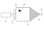
図1に、本実施形態における生体情報イメージング装置の構成例を説明する図を示す。生体情報イメージング装置は、光源(光制御部を含む)50と、音響波検出器55と、信号処理部(情報処理部)56とを備える。
(Configuration example of biological information imaging apparatus)
FIG. 1 illustrates a configuration example of a biological information imaging apparatus according to the present embodiment. The biological information imaging apparatus includes a light source (including a light control unit) 50, an
光源50は、パルス光53を生体51に照射するための手段である。必要に応じて光を生体51に導く光ファイバなどの光導波路を設けてもよい。光源50は、生体内に存在する特定の成分に吸収される特定の波長の光を照射する。光源としては数ナノから数百ナノ秒オーダーのパルス光を発生可能なパルス光源を少なくとも一つは備える。光源としてはレーザーが好ましいが、レーザーのかわりに発光ダイオードなどを用いることも可能である。レーザーとしては、固体レーザー、ガスレーザー、色素レーザー、半導体レーザーなど様々なレーザーを使用できる。なお、本実施形態においては、単一の光源の例を示しているが、複数の光源を用いてもよい。複数光源の場合は、生体に照射する光の照射強度を上げるため、同じ波長を発振する光源を複数用いても良いし、光学特性値分布の波長による違いを測定するために、発振波長の異なる光源を複数個用いても良い。なお、光源として、発振する波長の変換可能な色素やOPO(Optical Parametric Oscillators)を用いることができれば、光学特性値分布の波長による違いを測定することも可能になる。使用する波長に関しては、生体内において吸収が少ない700nmから1100nmの領域が好ましい。ただし、比較的生体表面付近の生体組織の光
学特性値分布を求める場合は、上記の波長領域よりも範囲の広い、例えば400nmから1600nmの波長領域を使用することも可能である。
The
音響波検出器55は、生体51に照射された光のエネルギーの一部を吸収した光吸収体52から発生する音響波54を検出し、電気信号に変換するための手段である。音響波検出器55から出力される電気信号は信号処理部56に入力される。音響波検出器55としては、圧電現象を用いたトランスデューサー、光の共振を用いたトランスデューサー、容量の変化を用いたトランスデューサーなどを用いることができる。光吸収体52としては、例えば、血管、腫瘍、その他これらに類する組織が該当する。なお本実施形態は、特に動きのある光吸収体のイメージングに好適である。
The
信号処理部56は、音響波検出器55から出力される電気信号を解析し、生体の光学特性値分布情報を得る機能である。また、信号処理部56は、少なくとも1画面分の画像情報(断層像または三次元像の画像データ)を記憶する画像メモリ(フレームメモリ)を有している。そして信号処理部56は、この画像メモリに蓄えられた第一の状態で取得された第一の画像と、別のタイミングの第二の状態で取得された第二の画像とを比較して、それらの差分を計算する機能を備える。信号処理部56は、電気信号の入力、データ(画像情報含む)の記憶および演算、演算結果の出力などの機能が実現できれば、どのような装置構成をとることも可能である。例えば解析プログラムを具備するコンピュータにより構成することができる。なお、信号処理部56の演算結果である光学特性値分布情報や差分画像情報などは表示装置(不図示)に出力される。
The
(差分画像の生成処理)
本実施形態でのPAT技術による撮像は、以下のフローにて行われる。なお光照射によって光吸収体から音響波が発生するメカニズムは前述した基本原理のフローと同様である。
(1)第一の状態において試料の外部から光を照射する。
(2)光吸収係数の大きい箇所から第一の音響波(超音波)が発生する。
(3)試料中を伝播した第一の音響波を試料の外部にて音響波検出器(超音波探触子)を用いて受信する(第一の測定工程)。
(4)到達音響波の時間差などを解析し、試料の第一の画像(断層像もしくは三次元像)を再構成する。
(5)取得した第一の画像を画像メモリに蓄積する(記憶工程)。
(6)第一の状態とは異なる第二の状態において試料の外部から光を照射する。
(7)光吸収係数の大きい箇所から第二の音響波(超音波)が発生する。
(8)試料中を伝播した第二の音響波を試料の外部にて音響波検出器(超音波探触子)を用いて受信する(第二の測定工程)。
(9)到達音響波の時間差などを解析し、試料の第二の画像(断層像もしくは三次元像)を再構成する。
(10)(9)で取得した第二の画像を、(5)で画像メモリに蓄積した第一の画像と比較し、差分を取得する(処理工程)。
(Difference image generation processing)
Imaging by the PAT technique in this embodiment is performed according to the following flow. The mechanism by which the acoustic wave is generated from the light absorber by light irradiation is the same as the basic principle flow described above.
(1) Light is irradiated from the outside of the sample in the first state.
(2) A first acoustic wave (ultrasonic wave) is generated from a portion having a large light absorption coefficient.
(3) The first acoustic wave propagated through the sample is received outside the sample using an acoustic wave detector (ultrasonic probe) (first measurement step).
(4) Analyzing the time difference of the reaching acoustic wave and reconstructing the first image (tomographic image or three-dimensional image) of the sample.
(5) Accumulating the acquired first image in the image memory (storage process).
(6) Light is irradiated from outside the sample in a second state different from the first state.
(7) A second acoustic wave (ultrasonic wave) is generated from a portion having a large light absorption coefficient.
(8) The second acoustic wave propagated through the sample is received outside the sample using an acoustic wave detector (ultrasonic probe) (second measurement step).
(9) Analyzing the time difference of the reaching acoustic wave and reconstructing a second image (tomographic image or three-dimensional image) of the sample.
(10) The second image acquired in (9) is compared with the first image stored in the image memory in (5), and a difference is acquired (processing step).
上記のフローによれば、異なるタイミングで第一の測定と第二の測定を行い、二つの異なる状態での像を画像再構成した後、これら2つの画像の差分を取得することによって、変化した部位のみを抽出することが可能である。なお、第一の測定と第二の測定は、測定対象の組織(血管や病変部位など)の形状が互いに異なるようなタイミングで行われる。 According to the above flow, the first measurement and the second measurement were performed at different timings, and after reconstructing the images in two different states, the difference was obtained by obtaining the difference between these two images. It is possible to extract only the part. Note that the first measurement and the second measurement are performed at timings such that the shapes of tissues to be measured (such as blood vessels and lesion sites) are different from each other.
(実施形態の利点)
以上述べた本発明の実施形態によれば、正しくフレーム間比較を行うことができるようになるため、差分を取得することによって変化している部分のみを抽出することが可能で
ある。すなわち従来の線順次で画像を取得する超音波診断装置では、上記課題で示した通り正しいフレーム間比較ができなかったのに対し、本実施形態の構成ではイメージングを行う際に、光音響トモグラフィーを用いている。この方法は超音波診断装置のように線順次で走査を行うわけではなく、光を照射することによってイメージングするために、生体内部の異なる場所の同時刻の情報を取得することが可能になる。この結果、フレーム間の差分画像から組織の状態変化の様子を正しく捉えることが可能となる。これを利用すれば、例えば血管像などの運動組織や、経時変化した病変部位などを鮮明に写し出すことが可能となる。
(Advantages of the embodiment)
According to the embodiment of the present invention described above, it is possible to correctly perform comparison between frames, and therefore it is possible to extract only a portion that has changed by acquiring a difference. That is, in the conventional ultrasonic diagnostic apparatus that acquires images in line-sequential manner, as shown in the above problem, correct comparison between frames could not be performed, but in the configuration of this embodiment, photoacoustic tomography is performed when performing imaging. Used. This method does not perform line-sequential scanning as in the case of an ultrasonic diagnostic apparatus, but it is possible to acquire information at the same time at different locations inside the living body in order to perform imaging by irradiating light. As a result, it is possible to correctly capture the state change of the tissue from the difference image between frames. If this is utilized, it becomes possible to clearly display, for example, a moving tissue such as a blood vessel image or a lesion site that has changed over time.
[実施例1]
本発明の実施例1について説明する。実施例1は、試料の全周囲で検出した超音波から画像再構成を行う例である。ここでは実際の測定時の様子を模した条件で行ったシミュレーションについて図面を用いて説明する。なお実際の測定あるいは診断では、3次元空間を考慮しなければならないが、本計算過程では二次元平面上での計算を示す。
[Example 1]
Example 1 of the present invention will be described. Example 1 is an example in which image reconstruction is performed from ultrasonic waves detected all around the sample. Here, simulations performed under conditions simulating actual measurement will be described with reference to the drawings. In actual measurement or diagnosis, a three-dimensional space must be considered, but in this calculation process, calculation on a two-dimensional plane is shown.
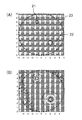
図2Aおよび図3Aは実施例1に用いるシミュレーションの実施条件を図示しており、サンプルの配置を表している。図2Aは第一の状態、図3Aは第二の状態を表している。ここで例えば図2Aにおいて、符号21と22は光吸収体である。これに任意の場所から一様な光を照射し(図示せず)、光吸収体21、22より発生する音響波を音響波検出器である超音波探触子23にて検知する。この超音波探触子23は、光吸収体21、22の全周囲を取り囲む略円形状を呈している。その円の上に描かれた60個の小さい円が、それぞれ超音波受信素子を表している。つまり、光吸収体21、22から発生する超音波を全周囲に配置された60個の超音波受信素子で検知する。図3Aにおいて、符号41と42は光吸収体を示し、符号43は超音波探触子を示している。図2Aと図3Aとの違いは、図中の左上に存在する光吸収体(21、41)の形状が異なる点である。
FIG. 2A and FIG. 3A illustrate the execution conditions of the simulation used in Example 1, and represent the arrangement of samples. 2A shows the first state, and FIG. 3A shows the second state. Here, for example, in FIG. 2A,
光音響効果によって発生する音響波に関し、吸収体の形状が球状であれば、その吸収体から発せられる音響波は計算によって解析的に求められ、それが実験と一致することが知られている。2次元平面上に限定した計算においては、吸収体の形状が円状であれば同様に計算可能である。つまりその超音波プロファイルは、振幅変化がゼロからいったん正の圧へと上昇し、負の圧へと下降した後にゼロに戻るという、「N」型の変化を示すことが知られている。このN字の幅は光吸収体の大きさ、N字の高さ(振幅)は式(1)で示す通り、光到達量と吸収係数の積に比例することが知られている。 Regarding the acoustic wave generated by the photoacoustic effect, if the shape of the absorber is spherical, it is known that the acoustic wave emitted from the absorber can be analytically obtained by calculation and agrees with the experiment. In the calculation limited to the two-dimensional plane, the calculation can be similarly performed if the shape of the absorber is circular. In other words, it is known that the ultrasonic profile exhibits an “N” type change in which the amplitude change once increases from zero to a positive pressure, decreases to a negative pressure, and then returns to zero. It is known that the width of the N-shape is the size of the light absorber, and the height (amplitude) of the N-shape is proportional to the product of the light arrival amount and the absorption coefficient, as shown by the equation (1).
光吸収体において発生した音響波は等方的に広がり、生体内を伝播し、超音波受信素子に到達する。複数の点で測定された到達音響波を、公知の解析手法を用いて画像化することができる。本実施例では、図2Aのサンプルにおいて60点で検出された音響波信号から、公知のCircular Backprojection法(CBP法)を用いて画像再構成を行い、第一の画像を得た。図2Bは第一の画像を示している。一方、図2Aと同様に図3Aのサンプルにて画像再構成を行い、第二の画像を得た。図3Bは第二の画像を示している。 The acoustic wave generated in the light absorber spreads isotropically, propagates in the living body, and reaches the ultrasonic receiving element. Reaching acoustic waves measured at a plurality of points can be imaged using a known analysis technique. In this example, image reconstruction was performed from the acoustic wave signals detected at 60 points in the sample of FIG. 2A using a known Circular Backprojection method (CBP method), and a first image was obtained. FIG. 2B shows the first image. On the other hand, as in FIG. 2A, image reconstruction was performed with the sample of FIG. 3A to obtain a second image. FIG. 3B shows a second image.
図2Bの画像と図3Bの画像とを並置して比較したとしても、二つの円状のものが共に存在するだけであるので、二つの画像の違いを即座に判別することは困難である。 Even if the image of FIG. 2B and the image of FIG. 3B are compared side by side, it is difficult to immediately discriminate the difference between the two images because only two circular objects exist together.
そこで、本実施例では、図2Bの画像と図3Bの画像との差分(画素間の濃度差)を計算し、得られた差分画像を出力する。図4は差分画像を示している。差分画像では、同一形状の部分(光吸収体22、42)が消去され、形状の異なる部分(光吸収体21、42)が抽出されている。このように、異なる状態で取得された二つの画像の差分を計算することにより、形状・位置・大きさなどが変化している部分のみが強調された画像を得るこ
とが可能となる。
Therefore, in this embodiment, the difference (density difference between pixels) between the image in FIG. 2B and the image in FIG. 3B is calculated, and the obtained difference image is output. FIG. 4 shows the difference image. In the difference image, portions having the same shape (
[実施例2]
本発明の実施例2について説明する。実施例2は、試料の片側で検出した超音波から画像再構成を行う例である。すなわち、実施例1では二つの光吸収体を取り囲むように超音波受信素子を配置したのに対し、実施例2では光吸収体に対して一方の側のみに超音波受信素子を配置する。ここでは実際の測定時の様子を模した条件で行ったシミュレーションについて図面を用いて説明する。なお実際の測定あるいは診断では、3次元空間を考慮しなければならないが、本計算過程では二次元平面上での計算を示す。
[Example 2]
A second embodiment of the present invention will be described. Example 2 is an example in which image reconstruction is performed from ultrasonic waves detected on one side of a sample. That is, in the first embodiment, the ultrasonic receiving elements are arranged so as to surround the two light absorbers, whereas in the second embodiment, the ultrasonic receiving elements are arranged only on one side with respect to the light absorber. Here, simulations performed under conditions simulating actual measurement will be described with reference to the drawings. In actual measurement or diagnosis, a three-dimensional space must be considered, but in this calculation process, calculation on a two-dimensional plane is shown.
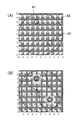
図5Aおよび図6Aは実施例2に用いるサンプルの配置を表している。図5Aは第一の状態、図6Aは第二の状態を表している。ここで例えば図5Aにおいて、符号71は棒状の光吸収体であり、符号72は円状の光吸収体である。これに任意の場所から一様な光を照射し(図示せず)、光吸収体71、72より発生する音響波を音響波検出器である超音波探触子73にて検知する。なお、図5Aと図6Aとの違いは、棒状の光吸収体(71、91)の太さが異なる点である。円状の光吸収体(72、92)の径は同一である。
5A and 6A show the arrangement of samples used in Example 2. FIG. FIG. 5A shows the first state, and FIG. 6A shows the second state. Here, for example, in FIG. 5A,
こうした配置において、実施例1と同様にして、CBP法を用いて画像再構成した。図5Aのサンプル配置において検出された超音波信号から再構成した結果である第一の画像を図5Bに示す。また図6Aのサンプル配置において検出された超音波信号から再構成した結果である第二の画像を図6Bに示す。 In such an arrangement, the image was reconstructed using the CBP method in the same manner as in Example 1. FIG. 5B shows a first image that is the result of reconstruction from the ultrasonic signals detected in the sample arrangement of FIG. 5A. Moreover, the 2nd image which is a result of having reconstructed from the ultrasonic signal detected in the sample arrangement | positioning of FIG. 6A is shown to FIG. 6B.
このように図5B、図6Bともに、棒状の光吸収体と円状の光吸収体の再構成像が一部重なり合い、良好な再構成像を得ることができていない。その結果、棒状の光吸収体の太さの違いを判別することが困難になっている。 As described above, in both FIG. 5B and FIG. 6B, the reconstructed images of the rod-shaped light absorber and the circular light absorber partially overlap, and a good reconstructed image cannot be obtained. As a result, it is difficult to determine the difference in the thickness of the rod-shaped light absorber.
それに対し、これらの画像データの差分を計算したものが図7である。図7では円状の光吸収体の像が差分計算によって消去されている。棒状の光吸収体の影響や、超音波信号の受信を片側だけで行っていることによる情報量の不足によって若干像は乱れているものの、形状の異なった棒状の部分が抽出されていることがわかる。このように、異なる状態で取得された二つの画像の差分を計算することにより、形状・位置・大きさなどが変化している部分のみが強調された画像を得ることが可能となる。 On the other hand, the difference between these image data is calculated as shown in FIG. In FIG. 7, the image of the circular light absorber is erased by the difference calculation. Although the image is slightly distorted due to the influence of the rod-shaped light absorber and the lack of information amount due to reception of ultrasonic signals only on one side, rod-shaped portions with different shapes are extracted Recognize. As described above, by calculating the difference between two images acquired in different states, it is possible to obtain an image in which only a portion whose shape, position, size, and the like are changed is emphasized.
[実施例3]
本発明の実施例3について説明する。実施例1、2では、画像再構成を行った後に画像データの差分像を生成することによって、状態変化した部分を抽出している。つまり、実空間において差分演算を行っている。これに対し、実施例3では、音響波信号を周波数領域に変換し、周波数領域において信号データの差分を取った後、その差分を空間領域に逆変換することにより得られたデータから差分画像を生成する。
[Example 3]
A third embodiment of the present invention will be described. In the first and second embodiments, the state-changed part is extracted by generating a differential image of image data after image reconstruction. That is, the difference calculation is performed in the real space. On the other hand, in Example 3, after converting the acoustic wave signal into the frequency domain, taking the difference of the signal data in the frequency domain, the difference image is obtained from the data obtained by inversely transforming the difference into the spatial domain. Generate.
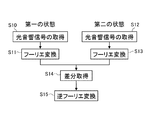
図8は、実施例3の処理の流れを示すフローチャートである。まず、第一の状態において、光照射および音響波検出を行い(ステップS10)、検出された音響波信号をフーリエ変換する(ステップS11)。フーリエ変換された1画像分の信号データは画像メモリに蓄積される。次に、第二の状態において、光照射および音響波検出を行い(ステップS12)、検出された音響波信号をフーリエ変換する(ステップS13)。そして、第一の状態で取得された信号データと第二の状態で取得された信号データとの差分を取り(ステップS14)、その差分データを逆フーリエ変換する(ステップS15)。逆フーリエ変換により得られた音響波信号の差分データから画像再構成が行われる。 FIG. 8 is a flowchart illustrating the flow of processing according to the third embodiment. First, in the first state, light irradiation and acoustic wave detection are performed (step S10), and the detected acoustic wave signal is Fourier transformed (step S11). The signal data for one image subjected to Fourier transform is stored in an image memory. Next, in the second state, light irradiation and acoustic wave detection are performed (step S12), and the detected acoustic wave signal is Fourier transformed (step S13). Then, the difference between the signal data acquired in the first state and the signal data acquired in the second state is taken (step S14), and the difference data is subjected to inverse Fourier transform (step S15). Image reconstruction is performed from difference data of acoustic wave signals obtained by inverse Fourier transform.
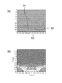
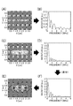
以下、図9A〜図9Fを用いて、実施例3のシミュレーション結果を説明する。実施例
3では、超音波探触子から2cmの距離に、3つの円状の光吸収体を1cm間隔で配置したサンプルを用いる。図9Aは、第一の状態で取得された音響波信号から再構成された画像であり、図9Bは、第一の状態で取得された音響波信号をフーリエ変換したデータである。また図9Cは、第二の状態で取得された音響波信号から再構成された画像であり、図9Dは、第二の状態で取得された音響波信号をフーリエ変換したデータである。第一の状態と第二の状態の違いは、第一の状態では光吸収体の直径が2mmであるのに対し、第二の状態では光吸収体の直径が4mmである点である。
Hereinafter, simulation results of Example 3 will be described with reference to FIGS. 9A to 9F. In Example 3, a sample in which three circular light absorbers are arranged at intervals of 1 cm at a distance of 2 cm from the ultrasonic probe is used. FIG. 9A is an image reconstructed from the acoustic wave signal acquired in the first state, and FIG. 9B is data obtained by Fourier transforming the acoustic wave signal acquired in the first state. FIG. 9C is an image reconstructed from the acoustic wave signal acquired in the second state, and FIG. 9D is data obtained by Fourier transforming the acoustic wave signal acquired in the second state. The difference between the first state and the second state is that the diameter of the light absorber is 2 mm in the first state, whereas the diameter of the light absorber is 4 mm in the second state.
図9Fは、図9Bに示す信号データと図9Dに示す信号データとの差分データである。この図9Fの差分データを逆フーリエ変換して画像化したものが、図9Eである。このように周波数空間にて差分を取得しても、状態の変化した部位を抽出することが可能である。 FIG. 9F shows difference data between the signal data shown in FIG. 9B and the signal data shown in FIG. 9D. FIG. 9E shows the difference data of FIG. 9F that has been imaged by inverse Fourier transform. Thus, even if the difference is acquired in the frequency space, it is possible to extract the part whose state has changed.
[その他の実施例]
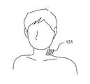
上記実施例の方法を利用することによって血管をイメージングすることができる。例えば実施例1の方法は、図10に示すように、指の周囲に超音波探触子121を配置し、超音波を測定する場合に利用できる。また実施例2の方法は、例えば図11に示すように、頸動脈に押し当てるようにして、血管に対して一方の側面に超音波探触子131を配置し、超音波を測定する場合に利用できる。
[Other Examples]
A blood vessel can be imaged by using the method of the above embodiment. For example, as shown in FIG. 10, the method of the first embodiment can be used when an
なお、いずれの場合も、超音波探触子と生体との間には音響インピーダンスの整合をとるためのマッチング剤などを用いることが好ましい。 In either case, it is preferable to use a matching agent or the like for matching acoustic impedance between the ultrasonic probe and the living body.
血管は血流によって時々刻々とその太さを変化させている。つまり心臓の鼓動と同期して、その太さを収縮させながら血液を流している。そこで、生体情報イメージング装置が心拍のモニタリングを行い、心拍と同期して光照射を行うことで、そのタイミングでの状態を画像として取得することが可能となる。具体的には、血圧が略最大血圧のとき(第一の状態)に第一の測定を行い、血圧が略最低血圧のとき(第二の状態)に第二の測定を行う。これにより高血圧状態の血管の画像と低血圧状態の血管の画像が得られる。そしてこれらの画像間の比較を行うことによって、血圧変化に伴う血管径が変化した部分のみを描出することが可能となる。 The thickness of blood vessels changes with the blood flow. In other words, in sync with the heartbeat, blood is flowing while contracting its thickness. Therefore, the biological information imaging apparatus monitors the heartbeat and performs light irradiation in synchronization with the heartbeat, so that the state at that timing can be acquired as an image. Specifically, the first measurement is performed when the blood pressure is approximately the maximum blood pressure (first state), and the second measurement is performed when the blood pressure is approximately the minimum blood pressure (second state). Thereby, an image of a blood vessel in a hypertensive state and an image of a blood vessel in a hypotensive state are obtained. Then, by comparing these images, it is possible to depict only the part where the blood vessel diameter has changed due to the blood pressure change.
ところで、心拍を測定する部位と診断する部位とが離れている場合には、必ずしも同期の取れた像が得られるとは限らない。この場合、第一の状態として安静状態にて測定し、その後、第二の状態として高心拍状態において測定すれば、血管像を正しくイメージングできる。つまり心拍数が互いに異なる第一の状態と第二の状態とで、血管の太さが一致するタイミングは極めてまれであるため、こうした状態間で差分を取れば血管のイメージングを行うことが可能となる。もし差分がうまく取れていない場合には、高心拍状態での測定を再度行えばイメージングできる確率が高まる。 By the way, when the site | part which measures a heart rate and the site | part to diagnose are separated, the image with which the synchronization was taken is not necessarily acquired. In this case, if measurement is performed in a resting state as the first state and then measurement is performed in a high heartbeat state as the second state, a blood vessel image can be correctly imaged. In other words, the timing at which the blood vessel thicknesses match in the first state and the second state where the heart rates are different from each other is extremely rare. Therefore, if the difference between these states is taken, blood vessel imaging can be performed. Become. If the difference is not good, the probability of imaging increases if the measurement in the high heart rate state is performed again.
なお、この二つの状態を作り出すために、ベッドで寝たり椅子に座ったりして休息した後に測定する状態を第一の状態とし、自発的に運動したり外部からの刺激やストレスを与えたりすることで高心拍状態にし、その後に測定する状態を第二の状態とすればよい。これにより、二つの状態の差分画像から血管のイメージングを行うことができる。 In addition, in order to create these two states, the state that is measured after sleeping in bed or sitting on a chair and resting is the first state, and exercises spontaneously or gives external stimulus or stress. Thus, the high heart rate state may be set, and the state measured thereafter may be the second state. Thereby, the blood vessel can be imaged from the difference image of the two states.
あるいはこうした高心拍状態にさせるような機能(例えばストレス付与機能)を有した装置を上記生体情報イメージング装置に組み込んでも良い。また生体情報イメージング装置が心拍数を計測する機能を有しており、高心拍状態か否かを自動で判断し第二の測定を行うタイミングを決定しても良い。 Alternatively, a device having a function (for example, a stress imparting function) that makes such a high heartbeat state may be incorporated in the biological information imaging device. In addition, the biological information imaging apparatus may have a function of measuring a heart rate, and it may be determined automatically whether or not it is in a high heart rate state, and the timing for performing the second measurement may be determined.
また、血圧の異なる状態間で比較してもよい。例えば、早朝の低血圧状態を第一の状態とし、このときの測定を第一の測定とする。次いで、活動する時間帯における高血圧状態を第二の状態とし、このときの測定を第二の測定とする。これら二つの状態間の差分を取得することによって、血管のイメージングを行うことが可能となる。また生体情報イメージング装置が血圧を計測する機能を有しており、低血圧状態か高血圧状態かを自動で判断しても良い。 Moreover, you may compare between the states from which a blood pressure differs. For example, the early morning hypotension state is the first state, and the measurement at this time is the first measurement. Next, the hypertensive state in the active time zone is the second state, and the measurement at this time is the second measurement. By obtaining the difference between these two states, it is possible to image a blood vessel. In addition, the biological information imaging apparatus has a function of measuring blood pressure, and may automatically determine whether the blood pressure is low or high blood pressure.
また、波長の異なる2種類の光を用いることによって、組織の違いを観測できることが知られている。例えば、波長によってヘモグロビンの酸化度が異なるため、波長を変えて測定することによって動脈と静脈をイメージングできることが知られている。 It is also known that the difference in tissue can be observed by using two types of light having different wavelengths. For example, since the degree of oxidation of hemoglobin varies depending on the wavelength, it is known that arteries and veins can be imaged by measuring at different wavelengths.
上記血管のイメージングを行う際には、動脈での血管太さの変化が大きいのに対し、静脈は血管の太さが血流によってもほとんど変わらない。つまり、静脈を状態が変動しない基準組織とみなすことができる。これを利用し、2状態間の差分を取得するときに、状態の変動しない基準組織同士、すなわち静脈同士が一致するように位置合わせを行うことで、位置ずれをほとんど生じることなく差分像を取得することが可能となる。 When the blood vessel is imaged, the change in the thickness of the blood vessel in the artery is large, whereas the thickness of the vein in the vein hardly changes depending on the blood flow. That is, the vein can be regarded as a reference tissue whose state does not change. Using this, when acquiring a difference between two states, a difference image is obtained with little positional deviation by aligning the reference tissues whose states do not change, that is, by matching the veins. It becomes possible to do.
まず静脈によるイメージングを行うために、酸素が結合していないヘモグロビンの吸収が多い波長帯(700乃至800nm)にて、第一の状態と第二の状態のイメージングを行う。次いで、酸化ヘモグロビンの吸収が多い波長帯(800乃至1000nm)にて、第一の状態と第二の状態のイメージングを行う。それらを画像再構成し、酸素が結合していないヘモグロビンの吸収が多い波長帯での再構成画像を静脈像ととらえ、第一の状態と第二の状態での静脈像同士が一致するようにレジストレーションを行う。その後、その位置にて酸化ヘモグロビンを吸収する波長での再構成画像同士の差分を取得する。 First, in order to perform imaging with veins, imaging in the first state and the second state is performed in a wavelength band (700 to 800 nm) where absorption of hemoglobin to which oxygen is not bonded is large. Next, imaging in the first state and the second state is performed in a wavelength band (800 to 1000 nm) in which absorption of oxyhemoglobin is large. Images are reconstructed so that the reconstructed images in the wavelength band where the absorption of hemoglobin to which oxygen is not bound are large are regarded as vein images, so that the vein images in the first state and the second state match. Register. Thereafter, the difference between the reconstructed images at the wavelength at which the oxygenated hemoglobin is absorbed at that position is acquired.
こうした手順によって差分画像を得ることで、より正確に動脈のイメージングを行うことが可能となる。 By obtaining the difference image by such a procedure, it becomes possible to image the artery more accurately.
21、22、41、42 光吸収体
23、43 超音波探触子
50 光源
51 生体
52 光吸収体
53 パルス光
54 音響波
55 音響波検出器
56 信号処理部
71、72、91、92 光吸収体
73、93 超音波探触子
121、131 超音波探触子
21, 22, 41, 42
Claims (11)
前記測定手段による第一の測定で得られた第一の情報を記憶する記憶手段と、
前記測定手段による第二の測定で得られた第二の情報と、前記記憶手段に記憶された前記第一の情報とを用いて、前記生体内の組織の情報を画像化する情報処理手段と、
を備えることを特徴とする生体情報イメージング装置。 A measuring means for irradiating a living body with light and measuring an acoustic wave generated by the tissue in the living body absorbing the light;
Storage means for storing first information obtained by the first measurement by the measurement means;
Information processing means for imaging tissue information in the living body using second information obtained by the second measurement by the measurement means and the first information stored in the storage means; ,
A biological information imaging apparatus comprising:
前記情報処理手段は、前記第一の情報と前記第二の情報との差分を表す差分画像を生成するものであることを特徴とする請求項1に記載の生体情報イメージング装置。 The second measurement is performed at a timing when the shape of the tissue is different from the first measurement,
The biological information imaging apparatus according to claim 1, wherein the information processing unit generates a difference image representing a difference between the first information and the second information.
前記情報処理手段は、各波長の光により得られる音響波信号から画像を再構成し、該画像から状態が変化しない基準組織と状態が変化する組織とを検知し、前記第一の情報と前記第二の情報との差分を取得する際に、前記状態が変化しない基準組織を基準に位置合わせを行うことを特徴とする請求項2〜8のうちいずれか1項に記載の生体情報イメージング装置。 The measuring means uses light of at least two different wavelengths, measures an acoustic wave signal obtained by light of each wavelength,
The information processing means reconstructs an image from acoustic wave signals obtained from light of each wavelength, detects a reference tissue whose state does not change and a tissue whose state changes from the image, and the first information and the The biological information imaging apparatus according to any one of claims 2 to 8, wherein when obtaining a difference from the second information, alignment is performed with reference to a reference tissue in which the state does not change. .
前記第一の測定工程で得られた第一の情報を記憶する記憶工程と、
生体に光を照射し、前記生体内の組織が光を吸収することによって発生する音響波を測定する第二の測定工程と、
前記第二の測定工程で得られた第二の情報と、前記記憶工程で記憶された前記第一の情報とを用いて、前記生体内の組織の情報を画像化する処理工程と、
を含むことを特徴とする生体情報イメージング方法。 A first measurement step of irradiating a living body with light and measuring an acoustic wave generated by the tissue in the living body absorbing light;
A storage step of storing the first information obtained in the first measurement step;
A second measuring step of irradiating the living body with light and measuring an acoustic wave generated by the tissue in the living body absorbing the light;
Using the second information obtained in the second measurement step and the first information stored in the storage step, a processing step of imaging the tissue information in the living body,
A biological information imaging method comprising:
Priority Applications (4)
| Application Number | Priority Date | Filing Date | Title |
|---|---|---|---|
| JP2008211993A JP5460000B2 (en) | 2008-08-20 | 2008-08-20 | Imaging apparatus and imaging method |
| US12/544,834 US8864667B2 (en) | 2008-08-20 | 2009-08-20 | Biological information imaging apparatus and biological information imaging method |
| US14/481,984 US20140378814A1 (en) | 2008-08-20 | 2014-09-10 | Biological information imaging apparatus and biological information imaging method |
| US15/912,849 US20180192883A1 (en) | 2008-08-20 | 2018-03-06 | Biological information imaging apparatus and biological information imaging method |
Applications Claiming Priority (1)
| Application Number | Priority Date | Filing Date | Title |
|---|---|---|---|
| JP2008211993A JP5460000B2 (en) | 2008-08-20 | 2008-08-20 | Imaging apparatus and imaging method |
Publications (2)
| Publication Number | Publication Date |
|---|---|
| JP2010046215A true JP2010046215A (en) | 2010-03-04 |
| JP5460000B2 JP5460000B2 (en) | 2014-04-02 |
Family
ID=41697016
Family Applications (1)
| Application Number | Title | Priority Date | Filing Date |
|---|---|---|---|
| JP2008211993A Expired - Fee Related JP5460000B2 (en) | 2008-08-20 | 2008-08-20 | Imaging apparatus and imaging method |
Country Status (2)
| Country | Link |
|---|---|
| US (3) | US8864667B2 (en) |
| JP (1) | JP5460000B2 (en) |
Cited By (23)
| Publication number | Priority date | Publication date | Assignee | Title |
|---|---|---|---|---|
| JP2011206192A (en) * | 2010-03-29 | 2011-10-20 | Canon Inc | Photoacoustic imaging apparatus, photoacoustic imaging method, and program for executing the photoacoustic imaging method |
| WO2013018627A1 (en) | 2011-07-29 | 2013-02-07 | 富士フイルム株式会社 | Photoacoustic image-generating apparatus and acoustic unit |
| WO2013047250A1 (en) | 2011-09-27 | 2013-04-04 | 富士フイルム株式会社 | Laser source unit and optical acoustic image generation device |
| JP2013176414A (en) * | 2012-02-28 | 2013-09-09 | Fujifilm Corp | Photoacoustic image generating apparatus and method |
| JP2013188311A (en) * | 2012-03-13 | 2013-09-26 | Canon Inc | Signal processor used for subject information acquisition apparatus and method for acquiring subject information |
| JP2014224806A (en) * | 2013-04-19 | 2014-12-04 | キヤノン株式会社 | Specimen information acquisition device |
| JP2015501175A (en) * | 2011-10-12 | 2015-01-15 | セノ メディカル インストルメンツ,インク. | System and method for acquiring photoacoustic data and generating a parameter map thereof |
| EP2737856A4 (en) * | 2011-07-29 | 2015-03-18 | Fujifilm Corp | Photoacoustic image-generating apparatus and acoustic unit |
| JP2015109948A (en) * | 2013-10-31 | 2015-06-18 | キヤノン株式会社 | Subject information acquisition device |
| JP2015142740A (en) * | 2015-02-26 | 2015-08-06 | キヤノン株式会社 | Optical acoustic device, information processor, and display method |
| JP2015198971A (en) * | 2015-07-07 | 2015-11-12 | 富士フイルム株式会社 | Photoacoustic imaging method and device |
| JP2016041158A (en) * | 2014-08-18 | 2016-03-31 | プレキシオン株式会社 | Photoacoustic imaging device |
| JP2016077447A (en) * | 2014-10-15 | 2016-05-16 | プレキシオン株式会社 | Photoacoustic wave signal converter and probe incorporating photoacoustic wave signal converter |
| JP2016077712A (en) * | 2014-10-21 | 2016-05-16 | プレキシオン株式会社 | Photoacoustic imaging device and photoacoustic imaging method |
| JP2016101420A (en) * | 2014-11-28 | 2016-06-02 | キヤノン株式会社 | Photoacoustic apparatus |
| JP2016104230A (en) * | 2016-02-08 | 2016-06-09 | キヤノン株式会社 | Subject information acquisition device and subject information acquisition method |
| US9392944B2 (en) | 2011-07-29 | 2016-07-19 | Fujifilm Corporation | Laser source unit, control method thereof, photoacoustic image generation apparatus and photoacoustic image generation method |
| JP2016215002A (en) * | 2016-09-27 | 2016-12-22 | キヤノン株式会社 | Photoacoustic imaging apparatus, photoacoustic imaging method, and program for executing photoacoustic imaging method |
| JP2017000897A (en) * | 2016-10-13 | 2017-01-05 | キヤノン株式会社 | Method |
| JP2017100032A (en) * | 2017-03-09 | 2017-06-08 | キヤノン株式会社 | Subject information acquisition device and subject information acquisition method |
| JP2017131334A (en) * | 2016-01-26 | 2017-08-03 | キヤノン株式会社 | Subject information acquisition device and subject information acquisition method |
| WO2018087984A1 (en) * | 2016-11-11 | 2018-05-17 | 富士フイルム株式会社 | Photoacoustic image evaluation device, method, and program, and photoacoustic image generating device |
| US10243318B2 (en) | 2014-03-27 | 2019-03-26 | Fujifilm Corporation | Laser device and photoacoustic measurement device comprising the same |
Families Citing this family (24)
| Publication number | Priority date | Publication date | Assignee | Title |
|---|---|---|---|---|
| US10226206B2 (en) | 2007-04-11 | 2019-03-12 | The Board Of Regents Of The University Of Texas System | Systems and methods for measuring neonatal cerebral oxygenation |
| US9380967B2 (en) | 2007-04-11 | 2016-07-05 | The Board Of Regents Of The University Of Texas System | Systems and methods for measuring fetal cerebral oxygenation |
| JP5349839B2 (en) * | 2007-06-22 | 2013-11-20 | キヤノン株式会社 | Biological information imaging device |
| CN102131463B (en) * | 2008-08-27 | 2013-01-16 | 佳能株式会社 | Device for processing information relating to living body and method for processing information relating to living body |
| JP5419404B2 (en) * | 2008-09-04 | 2014-02-19 | キヤノン株式会社 | Photoacoustic device |
| JP2010088627A (en) * | 2008-10-07 | 2010-04-22 | Canon Inc | Apparatus and method for processing biological information |
| US7802737B2 (en) * | 2008-11-13 | 2010-09-28 | Richard D Rayner | Vehicle mounted, digital positioning spray system |
| JP5692988B2 (en) * | 2009-10-19 | 2015-04-01 | キヤノン株式会社 | Acoustic wave measuring device |
| JP5412242B2 (en) * | 2009-11-05 | 2014-02-12 | 伸治 久米 | Ultrasonic tomographic image processing device |
| JP5528083B2 (en) | 2009-12-11 | 2014-06-25 | キヤノン株式会社 | Image generating apparatus, image generating method, and program |
| JP5675390B2 (en) * | 2010-02-09 | 2015-02-25 | キヤノン株式会社 | measuring device |
| JP5709399B2 (en) | 2010-04-02 | 2015-04-30 | キヤノン株式会社 | SUBJECT INFORMATION ACQUISITION DEVICE, ITS CONTROL METHOD, AND PROGRAM |
| JP5777358B2 (en) | 2010-04-27 | 2015-09-09 | キヤノン株式会社 | Subject information acquisition apparatus and signal processing method |
| KR101273585B1 (en) * | 2011-12-05 | 2013-06-11 | 삼성전자주식회사 | Ultrasound imaging apparatus and display method of ultrasound image |
| JP6146955B2 (en) * | 2012-03-13 | 2017-06-14 | キヤノン株式会社 | Apparatus, display control method, and program |
| WO2014030491A1 (en) * | 2012-08-20 | 2014-02-27 | 株式会社アドバンテスト | Photoacoustic wave meter |
| JP6184146B2 (en) | 2013-03-26 | 2017-08-23 | キヤノン株式会社 | Subject information acquisition apparatus and control method thereof |
| KR20150084559A (en) * | 2014-01-14 | 2015-07-22 | 삼성메디슨 주식회사 | Photoacoustic apparatus and operating method for the same |
| EP3166494A4 (en) | 2014-07-08 | 2018-03-21 | The Board of Regents of The University of Texas System | Systems and methods for measuring fetal cerebral oxygenation |
| AU2016233575A1 (en) | 2015-03-14 | 2017-07-13 | The Board Of Regents Of The University Of Texas System | Systems and methods for measuring neonatal cerebral oxygenation |
| CN104840190A (en) * | 2015-05-15 | 2015-08-19 | 江西科技师范大学 | Optoacoustic effect-based heart rate measuring method and device |
| JP2017148230A (en) | 2016-02-24 | 2017-08-31 | キヤノン株式会社 | Subject information acquisition device and information processing device |
| US20170325693A1 (en) * | 2016-05-10 | 2017-11-16 | Canon Kabushiki Kaisha | Photoacoustic apparatus and control method of photoacoustic apparatus |
| CN107506687B (en) * | 2017-07-17 | 2020-01-21 | Oppo广东移动通信有限公司 | Living body detection method and related product |
Citations (16)
| Publication number | Priority date | Publication date | Assignee | Title |
|---|---|---|---|---|
| JPH03114452A (en) * | 1989-09-29 | 1991-05-15 | Terumo Corp | Ultrasonic diagnostic apparatus |
| JPH04208143A (en) * | 1990-10-12 | 1992-07-29 | Hitachi Medical Corp | Ultrasonic diagnostic apparatus |
| JPH05317313A (en) * | 1992-05-15 | 1993-12-03 | Ken Ishihara | Ultrasonic diagnosing apparatus |
| JPH0731615A (en) * | 1993-07-23 | 1995-02-03 | Ge Yokogawa Medical Syst Ltd | Image data processing method and apparatus for ultrasonic diagnostic apparatus |
| JPH114826A (en) * | 1997-06-17 | 1999-01-12 | Hiroaki Ookawai | Living body measuring device |
| JPH11125620A (en) * | 1997-08-08 | 1999-05-11 | Bio Rad Lab Inc | Dsp technique for sample pulse response of photoacoustic spectrometry(pas) for detecting depth cross section structure |
| JPH11137548A (en) * | 1997-11-11 | 1999-05-25 | Ge Yokogawa Medical Systems Ltd | Method and apparatus for ultrasonic imaging and method for destroying microballoon |
| JP2002045361A (en) * | 2000-08-01 | 2002-02-12 | Sensor:Kk | Measuring instrument for modulus of longitudinal elasticity of vital blood vessel tissue |
| JP2004344672A (en) * | 2004-07-09 | 2004-12-09 | Toshiba Corp | Ultrasonic treatment apparatus |
| JP2005021380A (en) * | 2003-07-02 | 2005-01-27 | Toshiba Corp | Living body information imaging apparatus |
| JP2006521869A (en) * | 2003-04-01 | 2006-09-28 | グルコン インク | Photoacoustic analysis evaluation method and apparatus |
| WO2006111939A2 (en) * | 2005-04-22 | 2006-10-26 | Koninklijke Philips Electronics N.V. | Canulla inserting system having tissue analysis means |
| JP2007057512A (en) * | 2005-08-26 | 2007-03-08 | Toyohashi Univ Of Technology | Measurement method for object under inspection and measuring instrument for object under inspection |
| WO2007084981A2 (en) * | 2006-01-19 | 2007-07-26 | The Regents Of The University Of Michigan | System and method for photoacoustic imaging and monitoring of laser therapy |
| WO2007088709A1 (en) * | 2006-01-31 | 2007-08-09 | Kansai Technology Licensing Organization Co., Ltd. | 3d acoustic imaging device and 3d acoustic imaging method |
| WO2008075299A1 (en) * | 2006-12-19 | 2008-06-26 | Koninklijke Philips Electronics, N.V. | Combined photoacoustic and ultrasound imaging system |
Family Cites Families (18)
| Publication number | Priority date | Publication date | Assignee | Title |
|---|---|---|---|---|
| JPS62189054A (en) | 1986-02-17 | 1987-08-18 | 株式会社 日立メデイコ | Ultrasonic diagnostic apparatus |
| JPH0827264B2 (en) * | 1988-09-21 | 1996-03-21 | 工業技術院長 | Photoacoustic imaging method with multiple modulation frequencies |
| US5152290A (en) * | 1991-02-13 | 1992-10-06 | Prism Imaging, Inc. | Method for recording ultrasound images to diagnose heart and coronary artery disease |
| US5359513A (en) * | 1992-11-25 | 1994-10-25 | Arch Development Corporation | Method and system for detection of interval change in temporally sequential chest images |
| US6004270A (en) * | 1998-06-24 | 1999-12-21 | Ecton, Inc. | Ultrasound system for contrast agent imaging and quantification in echocardiography using template image for image alignment |
| US6267728B1 (en) * | 1999-06-23 | 2001-07-31 | Steven Mark Hayden | Method for evaluating atherosclerosis and its affect on the elasticity of arterial walls |
| US20030149358A1 (en) * | 2002-02-06 | 2003-08-07 | Nissan Maskil | Ultrasonic system for non-invasive early prostate cancer detection |
| US8328420B2 (en) * | 2003-04-22 | 2012-12-11 | Marcio Marc Abreu | Apparatus and method for measuring biologic parameters |
| US7314446B2 (en) * | 2002-07-22 | 2008-01-01 | Ep Medsystems, Inc. | Method and apparatus for time gating of medical images |
| JP3872424B2 (en) * | 2002-12-20 | 2007-01-24 | アロカ株式会社 | Ultrasonic diagnostic equipment |
| IL164030A0 (en) * | 2003-09-12 | 2005-12-18 | Revital Pery Shechter | Photoacoustic analyzer of a region of interest in a human body |
| US20050107704A1 (en) * | 2003-11-14 | 2005-05-19 | Von Behren Patrick L. | Motion analysis methods and systems for medical diagnostic ultrasound |
| WO2008085193A2 (en) * | 2006-08-14 | 2008-07-17 | University Of Maryland | Quantitative real-time 4d strees test analysis |
| KR100871074B1 (en) * | 2007-02-01 | 2008-11-28 | 삼성전자주식회사 | Noninvasive apparatus and method for measuring blood glucose |
| JP4739363B2 (en) | 2007-05-15 | 2011-08-03 | キヤノン株式会社 | Biological information imaging apparatus, biological information analysis method, and biological information imaging method |
| EP2002784B1 (en) | 2007-06-11 | 2018-07-11 | Canon Kabushiki Kaisha | Intravital-information imaging apparatus |
| JP5349839B2 (en) | 2007-06-22 | 2013-11-20 | キヤノン株式会社 | Biological information imaging device |
| JP5284129B2 (en) | 2008-02-06 | 2013-09-11 | キヤノン株式会社 | Imaging apparatus and analysis method |
-
2008
- 2008-08-20 JP JP2008211993A patent/JP5460000B2/en not_active Expired - Fee Related
-
2009
- 2009-08-20 US US12/544,834 patent/US8864667B2/en not_active Expired - Fee Related
-
2014
- 2014-09-10 US US14/481,984 patent/US20140378814A1/en not_active Abandoned
-
2018
- 2018-03-06 US US15/912,849 patent/US20180192883A1/en not_active Abandoned
Patent Citations (16)
| Publication number | Priority date | Publication date | Assignee | Title |
|---|---|---|---|---|
| JPH03114452A (en) * | 1989-09-29 | 1991-05-15 | Terumo Corp | Ultrasonic diagnostic apparatus |
| JPH04208143A (en) * | 1990-10-12 | 1992-07-29 | Hitachi Medical Corp | Ultrasonic diagnostic apparatus |
| JPH05317313A (en) * | 1992-05-15 | 1993-12-03 | Ken Ishihara | Ultrasonic diagnosing apparatus |
| JPH0731615A (en) * | 1993-07-23 | 1995-02-03 | Ge Yokogawa Medical Syst Ltd | Image data processing method and apparatus for ultrasonic diagnostic apparatus |
| JPH114826A (en) * | 1997-06-17 | 1999-01-12 | Hiroaki Ookawai | Living body measuring device |
| JPH11125620A (en) * | 1997-08-08 | 1999-05-11 | Bio Rad Lab Inc | Dsp technique for sample pulse response of photoacoustic spectrometry(pas) for detecting depth cross section structure |
| JPH11137548A (en) * | 1997-11-11 | 1999-05-25 | Ge Yokogawa Medical Systems Ltd | Method and apparatus for ultrasonic imaging and method for destroying microballoon |
| JP2002045361A (en) * | 2000-08-01 | 2002-02-12 | Sensor:Kk | Measuring instrument for modulus of longitudinal elasticity of vital blood vessel tissue |
| JP2006521869A (en) * | 2003-04-01 | 2006-09-28 | グルコン インク | Photoacoustic analysis evaluation method and apparatus |
| JP2005021380A (en) * | 2003-07-02 | 2005-01-27 | Toshiba Corp | Living body information imaging apparatus |
| JP2004344672A (en) * | 2004-07-09 | 2004-12-09 | Toshiba Corp | Ultrasonic treatment apparatus |
| WO2006111939A2 (en) * | 2005-04-22 | 2006-10-26 | Koninklijke Philips Electronics N.V. | Canulla inserting system having tissue analysis means |
| JP2007057512A (en) * | 2005-08-26 | 2007-03-08 | Toyohashi Univ Of Technology | Measurement method for object under inspection and measuring instrument for object under inspection |
| WO2007084981A2 (en) * | 2006-01-19 | 2007-07-26 | The Regents Of The University Of Michigan | System and method for photoacoustic imaging and monitoring of laser therapy |
| WO2007088709A1 (en) * | 2006-01-31 | 2007-08-09 | Kansai Technology Licensing Organization Co., Ltd. | 3d acoustic imaging device and 3d acoustic imaging method |
| WO2008075299A1 (en) * | 2006-12-19 | 2008-06-26 | Koninklijke Philips Electronics, N.V. | Combined photoacoustic and ultrasound imaging system |
Cited By (28)
| Publication number | Priority date | Publication date | Assignee | Title |
|---|---|---|---|---|
| JP2011206192A (en) * | 2010-03-29 | 2011-10-20 | Canon Inc | Photoacoustic imaging apparatus, photoacoustic imaging method, and program for executing the photoacoustic imaging method |
| US10390706B2 (en) | 2010-03-29 | 2019-08-27 | Canon Kabushiki Kaisha | Photoacoustic imaging apparatus, photoacoustic imaging method, and storage medium |
| WO2013018627A1 (en) | 2011-07-29 | 2013-02-07 | 富士フイルム株式会社 | Photoacoustic image-generating apparatus and acoustic unit |
| EP2737856A4 (en) * | 2011-07-29 | 2015-03-18 | Fujifilm Corp | Photoacoustic image-generating apparatus and acoustic unit |
| US9392944B2 (en) | 2011-07-29 | 2016-07-19 | Fujifilm Corporation | Laser source unit, control method thereof, photoacoustic image generation apparatus and photoacoustic image generation method |
| US9380944B2 (en) | 2011-07-29 | 2016-07-05 | Fujifilm Corporation | Photoacoustic image generation apparatus and acoustic wave unit |
| US9486144B2 (en) | 2011-07-29 | 2016-11-08 | Fujifilm Corporation | Photoacoustic image generation apparatus and acoustic wave unit |
| WO2013047250A1 (en) | 2011-09-27 | 2013-04-04 | 富士フイルム株式会社 | Laser source unit and optical acoustic image generation device |
| JP2015501175A (en) * | 2011-10-12 | 2015-01-15 | セノ メディカル インストルメンツ,インク. | System and method for acquiring photoacoustic data and generating a parameter map thereof |
| JP2013176414A (en) * | 2012-02-28 | 2013-09-09 | Fujifilm Corp | Photoacoustic image generating apparatus and method |
| JP2013188311A (en) * | 2012-03-13 | 2013-09-26 | Canon Inc | Signal processor used for subject information acquisition apparatus and method for acquiring subject information |
| JP2014224806A (en) * | 2013-04-19 | 2014-12-04 | キヤノン株式会社 | Specimen information acquisition device |
| JP2015109948A (en) * | 2013-10-31 | 2015-06-18 | キヤノン株式会社 | Subject information acquisition device |
| US10243318B2 (en) | 2014-03-27 | 2019-03-26 | Fujifilm Corporation | Laser device and photoacoustic measurement device comprising the same |
| JP2016041158A (en) * | 2014-08-18 | 2016-03-31 | プレキシオン株式会社 | Photoacoustic imaging device |
| JP2016077447A (en) * | 2014-10-15 | 2016-05-16 | プレキシオン株式会社 | Photoacoustic wave signal converter and probe incorporating photoacoustic wave signal converter |
| JP2016077712A (en) * | 2014-10-21 | 2016-05-16 | プレキシオン株式会社 | Photoacoustic imaging device and photoacoustic imaging method |
| JP2016101420A (en) * | 2014-11-28 | 2016-06-02 | キヤノン株式会社 | Photoacoustic apparatus |
| JP2015142740A (en) * | 2015-02-26 | 2015-08-06 | キヤノン株式会社 | Optical acoustic device, information processor, and display method |
| JP2015198971A (en) * | 2015-07-07 | 2015-11-12 | 富士フイルム株式会社 | Photoacoustic imaging method and device |
| JP2017131334A (en) * | 2016-01-26 | 2017-08-03 | キヤノン株式会社 | Subject information acquisition device and subject information acquisition method |
| JP2016104230A (en) * | 2016-02-08 | 2016-06-09 | キヤノン株式会社 | Subject information acquisition device and subject information acquisition method |
| JP2016215002A (en) * | 2016-09-27 | 2016-12-22 | キヤノン株式会社 | Photoacoustic imaging apparatus, photoacoustic imaging method, and program for executing photoacoustic imaging method |
| JP2017000897A (en) * | 2016-10-13 | 2017-01-05 | キヤノン株式会社 | Method |
| WO2018087984A1 (en) * | 2016-11-11 | 2018-05-17 | 富士フイルム株式会社 | Photoacoustic image evaluation device, method, and program, and photoacoustic image generating device |
| JPWO2018087984A1 (en) * | 2016-11-11 | 2019-09-26 | 富士フイルム株式会社 | Photoacoustic image evaluation apparatus, method and program, and photoacoustic image generation apparatus |
| US11710290B2 (en) | 2016-11-11 | 2023-07-25 | Fujifilm Corporation | Photoacoustic image evaluation apparatus, method, and program, and photoacoustic image generation apparatus |
| JP2017100032A (en) * | 2017-03-09 | 2017-06-08 | キヤノン株式会社 | Subject information acquisition device and subject information acquisition method |
Also Published As
| Publication number | Publication date |
|---|---|
| US20180192883A1 (en) | 2018-07-12 |
| JP5460000B2 (en) | 2014-04-02 |
| US20140378814A1 (en) | 2014-12-25 |
| US20100049049A1 (en) | 2010-02-25 |
| US8864667B2 (en) | 2014-10-21 |
Similar Documents
| Publication | Publication Date | Title |
|---|---|---|
| JP5460000B2 (en) | Imaging apparatus and imaging method | |
| JP5586977B2 (en) | Subject information acquisition apparatus and subject information acquisition method | |
| US8260403B2 (en) | Photoacoustic imaging apparatus and photoacoustic imaging method | |
| JP5850633B2 (en) | Subject information acquisition device | |
| US10143381B2 (en) | Object information acquiring apparatus and control method therefor | |
| CN100512764C (en) | Ultrasonograph and ultrasonography | |
| JP6632257B2 (en) | Subject information acquisition device | |
| EP2319415A1 (en) | Device for processing photo acoustic information relating to living body and method for processing photo acoustic information relating to living body | |
| US8942058B2 (en) | Display data obtaining apparatus and display data obtaining method | |
| US20140196544A1 (en) | Object information acquiring apparatus | |
| US9782081B2 (en) | Photoacoustic apparatus | |
| JP6132466B2 (en) | Subject information acquisition apparatus and subject information acquisition method | |
| CN106560160A (en) | Object Information Acquiring Apparatus And Control Method Thereof | |
| JP2016101415A (en) | Subject information acquisition apparatus | |
| JP6656229B2 (en) | Photoacoustic device | |
| CN108601536A (en) | Information acquisition device and control method | |
| JP2018061725A (en) | Subject information acquisition device and signal processing method | |
| US20170325693A1 (en) | Photoacoustic apparatus and control method of photoacoustic apparatus | |
| JP2017164198A (en) | Information processing system and display control method | |
| US20170265749A1 (en) | Processing apparatus and processing method | |
| JP2019107421A (en) | Photoacoustic apparatus and analyte information acquisition method | |
| JP2016152879A (en) | Subject information acquisition apparatus | |
| US20230404520A1 (en) | Methods and systems for photoacoustic computed tomography of blood flow | |
| JP6513121B2 (en) | Processing apparatus, object information acquiring apparatus, display method of photoacoustic image, and program | |
| JP2016013189A (en) | Photoacoustic apparatus |
Legal Events
| Date | Code | Title | Description |
|---|---|---|---|
| A621 | Written request for application examination |
Free format text: JAPANESE INTERMEDIATE CODE: A621 Effective date: 20110809 |
|
| A977 | Report on retrieval |
Free format text: JAPANESE INTERMEDIATE CODE: A971007 Effective date: 20130625 |
|
| A131 | Notification of reasons for refusal |
Free format text: JAPANESE INTERMEDIATE CODE: A131 Effective date: 20130903 |
|
| A521 | Request for written amendment filed |
Free format text: JAPANESE INTERMEDIATE CODE: A523 Effective date: 20131031 |
|
| TRDD | Decision of grant or rejection written | ||
| A01 | Written decision to grant a patent or to grant a registration (utility model) |
Free format text: JAPANESE INTERMEDIATE CODE: A01 Effective date: 20131217 |
|
| A61 | First payment of annual fees (during grant procedure) |
Free format text: JAPANESE INTERMEDIATE CODE: A61 Effective date: 20140114 |
|
| R151 | Written notification of patent or utility model registration |
Ref document number: 5460000 Country of ref document: JP Free format text: JAPANESE INTERMEDIATE CODE: R151 |
|
| LAPS | Cancellation because of no payment of annual fees |