JP2010044343A - Electronic imaging apparatus - Google Patents
Electronic imaging apparatus Download PDFInfo
- Publication number
- JP2010044343A JP2010044343A JP2008278464A JP2008278464A JP2010044343A JP 2010044343 A JP2010044343 A JP 2010044343A JP 2008278464 A JP2008278464 A JP 2008278464A JP 2008278464 A JP2008278464 A JP 2008278464A JP 2010044343 A JP2010044343 A JP 2010044343A
- Authority
- JP
- Japan
- Prior art keywords
- lens
- lens group
- image
- positive
- wide
- Prior art date
- Legal status (The legal status is an assumption and is not a legal conclusion. Google has not performed a legal analysis and makes no representation as to the accuracy of the status listed.)
- Granted
Links
Images


Classifications
-
- G—PHYSICS
- G02—OPTICS
- G02B—OPTICAL ELEMENTS, SYSTEMS OR APPARATUS
- G02B15/00—Optical objectives with means for varying the magnification
- G02B15/14—Optical objectives with means for varying the magnification by axial movement of one or more lenses or groups of lenses relative to the image plane for continuously varying the equivalent focal length of the objective
- G02B15/144—Optical objectives with means for varying the magnification by axial movement of one or more lenses or groups of lenses relative to the image plane for continuously varying the equivalent focal length of the objective having four groups only
- G02B15/1441—Optical objectives with means for varying the magnification by axial movement of one or more lenses or groups of lenses relative to the image plane for continuously varying the equivalent focal length of the objective having four groups only the first group being positive
- G02B15/144113—Optical objectives with means for varying the magnification by axial movement of one or more lenses or groups of lenses relative to the image plane for continuously varying the equivalent focal length of the objective having four groups only the first group being positive arranged +-++
Abstract
Description
本発明は、ズームレンズを用いた電子撮像装置に関し、特に小型化を実現した、ビデオカメラやデジタルカメラをはじめとする電子撮像装置に関するものである。 The present invention relates to an electronic image pickup apparatus using a zoom lens, and more particularly to an electronic image pickup apparatus such as a video camera or a digital camera that has been downsized.
近年では、銀塩フィルムカメラに代わり、CCDやCMOSのような固体撮像素子を用いて被写体を撮影するようにしたデジタルカメラが主流となっている。更に、それは業務用高機能タイプからコンパクトな普及タイプまで幅広い範囲でいくつものカテゴリーを有するようになってきている。本発明においては、特にコンパクトな普及タイプのカテゴリーに注目している。 In recent years, digital cameras that shoot a subject using a solid-state imaging device such as a CCD or CMOS instead of a silver salt film camera have become mainstream. Furthermore, it has come to have a number of categories in a wide range from a high-functional type for business use to a compact popular type. In the present invention, attention is focused on a category of a compact popular type.
このような普及タイプのデジタルカメラのユーザーは、いつでもどこでも手軽に幅広いシーンで撮影を楽しみたいという要望をもっている。そのため、小型な商品、特に服やカバンのポケット等への収納性がよく持ち運びが便利な、厚み方向のサイズが薄型であるタイプのデジタルカメラが好まれるようになっており、撮影レンズ系にもより一層の小型化が要望されている。一方、撮像素子の画素数が増加の傾向にあるため、撮像素子の高画素化に対応した高い光学性能が求められている。さらには量産性も確保するために、レンズ加工や組み込み工程での製造誤差に対する光学性能劣化の感度を小さく抑えておく必要がある。また撮影領域を広げるという観点から変倍比が5倍や7倍を超える高変倍ズームも一般化してきており、更なる高変倍化も期待されている一方で、広角化への期待もある。こういった要求に応えるべく様々なタイプのズームレンズ系が提案されている。 Users of such popular digital cameras have a desire to enjoy shooting in a wide range of scenes anytime and anywhere. For this reason, digital cameras with a small size in the thickness direction are favored because they are easy to carry in small products, especially clothes and bag pockets. There is a demand for further miniaturization. On the other hand, since the number of pixels of the image sensor tends to increase, high optical performance corresponding to the increase in the number of pixels of the image sensor is required. Furthermore, in order to secure mass productivity, it is necessary to keep the sensitivity of optical performance degradation to a manufacturing error in lens processing and assembling processes small. In addition, from the viewpoint of widening the shooting area, high zoom ratios with zoom ratios exceeding 5x and 7x have become commonplace, and even higher zoom ratios are expected. is there. Various types of zoom lens systems have been proposed to meet these requirements.
比較的高変倍比でコンパクトなズームレンズを構成した先行技術としては、物体側より正の第1レンズ群、負の第2レンズ群、正の第3レンズ群、正の第4レンズ群を有するタイプが知られており、以下のような技術が開示されている。
しかしながら、特許文献1で提案されているズームレンズは、レンズ系の全長が大きいため小型化に向かない。特許文献2又は特許文献3で提案されているズームレンズでは、十分な光学性能が確保されていない。
However, the zoom lens proposed in
上記いずれの先行技術においてもズーム全域において撮像素子への光線の入射角度が小さくなるように設計されており、変倍比を大きくしながら、良好な結像性能と小型化とを両立することができていない。 In any of the above prior arts, the incident angle of the light beam to the image pickup device is designed to be small in the entire zoom range, and it is possible to achieve both good imaging performance and downsizing while increasing the zoom ratio. Not done.
特許文献4で提案されているズームレンズは、銀塩フィルムを用いた一眼レフカメラ用として使うことを前提にしており、ズームレンズの光学系からの光線の射出角が大きい割にはミラースペースを確保するためバックフォーカスを長く取っているので、このようなパワー配置では、十分な結像性能を得るためにはレンズ枚数が多くなり、小さな撮像素子に対応する場合には小型化が難しい。 The zoom lens proposed in Patent Document 4 is assumed to be used for a single-lens reflex camera using a silver salt film, and a mirror space is required for a large light emission angle from the optical system of the zoom lens. Since a long back focus is used to ensure this, with such a power arrangement, the number of lenses increases in order to obtain sufficient imaging performance, and miniaturization is difficult when dealing with small image sensors.
本発明はこのような問題点に鑑みてなされたものであり、その目的は、カメラの携帯性
を損なうことなく、従来よりも撮影領域を広げたいというユーザーの要望を満たすべく、カメラの小型化と高変倍比化・広角化を同時に満たしており、撮影画像の画質が良好に維持された、CCDやCMOS等の電子撮像素子に適している安価なズームレンズ光学系を用いた電子撮像装置を提供することである。
The present invention has been made in view of such problems, and the purpose of the present invention is to reduce the size of the camera in order to satisfy the user's desire to expand the shooting area more than before without impairing the portability of the camera. Image pickup device using an inexpensive zoom lens optical system suitable for electronic image pickup devices such as CCDs and CMOSs, which satisfies both high zoom ratio and wide angle at the same time. Is to provide.
上記課題を解決するために、本発明では、ズームレンズは開口絞りよりも撮像素子側に少なくとも1つの正レンズを配し、以下の条件式(1)、(2)、(3)を満たすような構成とした。
|αt−αw|>8 ・・・(1)
1.0×10⁻³<P<4.0×10⁻³ ・・・(2)
4<ft/fw<50 ・・・(3)
ただし、fw:広角端でのズームレンズ全系の焦点距離、
ft:望遠端でのズームレンズ全系の焦点距離、
である。
αw:広角端における最軸外×0.8の像高の主光線が撮像素子に入射するとき
光軸となす角度(°)で、撮像素子直前のレンズ面の光線高より撮像素子面の光線高が低い場合に正とする。また、光線高とは、光線がレンズ面に入射する位置と光軸との距離である。なお、最軸外とは、最大像高のことである。
αt:望遠端における最軸外×0.8の像高の光線が撮像素子に入射するとき光
軸となす角度(°)で、撮像素子直前のレンズ面の光線高より撮像素子面の光線高が低い場合に正とする。
P:撮像素子の画素ピッチ(単位はmm)
である。
In order to solve the above-described problem, in the present invention, the zoom lens has at least one positive lens disposed closer to the image sensor than the aperture stop, and satisfies the following conditional expressions (1), (2), and (3): The configuration was
| Α t −α w |> 8 (1)
1.0 × 10 −3 <P <4.0 × 10 −3 (2)
4 < ft / fw <50 (3)
Where f w is the focal length of the entire zoom lens system at the wide-angle end,
f t : focal length of the entire zoom lens system at the telephoto end,
It is.
α w is the angle (°) formed with the optical axis when the chief ray with the image height of off-axis x 0.8 at the wide-angle end is incident on the image sensor. Positive if the beam height is low. The ray height is the distance between the position where the ray enters the lens surface and the optical axis. In addition, the most off-axis is the maximum image height.
α t : Angle (°) formed with an optical axis when a light beam with an image height of 0.8 off-axis at the telephoto end is incident on the image sensor, and the light beam on the image sensor surface from the light beam height on the lens surface immediately before the image sensor Positive if the height is low.
P: Pixel pitch of the image sensor (unit: mm)
It is.
一般に、CCD等の電子撮像素子と結像光学系を用いた撮像装置においては、光学系の光軸に対して射出角が大きいと撮像素子の受光の効率が下がり、画面周辺部において、十分な光量を得ることができなくなり、画質が低下しやすい。しかしながら、撮像素子への入射角を光軸と平行になるようにズームレンズを設計しようとすると、高変倍化と小型化を両立することが困難である。本発明においては、絞りよりも像面側のレンズの屈折力と形状を適切に設定することにより、広角端及び望遠端の周辺光量と光線射出角のバランスを取りながら、高変倍且つ像面湾曲の変動を小さくするため、上記条件式を満たすようにレンズを配置した。 In general, in an image pickup apparatus using an electronic image pickup device such as a CCD and an imaging optical system, if the emission angle is large with respect to the optical axis of the optical system, the light receiving efficiency of the image pickup device is lowered, and sufficient in the periphery of the screen. The amount of light cannot be obtained, and the image quality tends to deteriorate. However, if an attempt is made to design a zoom lens so that the angle of incidence on the image sensor is parallel to the optical axis, it is difficult to achieve both high zooming and miniaturization. In the present invention, by appropriately setting the refractive power and shape of the lens closer to the image plane than the stop, it is possible to achieve high zoom ratio and image plane while balancing the peripheral light amount and the light emission angle at the wide-angle end and the telephoto end. In order to reduce the variation in curvature, the lens was arranged so as to satisfy the above conditional expression.
条件式(1)の上限内であれば、光学系の全長を長くなりすぎないように抑える事ができる。また、条件式(1)の下限内であれば、最終レンズ群による像面湾曲変動を抑えることができる。いずれの場合も、結像性能を良好に保ちながら高変倍化と小型化を両立するための条件となる。 If it is within the upper limit of conditional expression (1), the total length of the optical system can be suppressed so as not to become too long. Also, if it is within the lower limit of conditional expression (1), it is possible to suppress the field curvature variation due to the final lens group. In either case, this is a condition for achieving both high zooming and miniaturization while maintaining good imaging performance.
条件式(2)の上限内であれば、撮像素子の面積を大きくすることなく、撮影画像で十分な解像力を得ることができ、ズームレンズを小型化できる。また、条件式(2)の下限内であれば、光の回折により収差が小さくても画素ピッチに対して十分な解像力が得られなくなるのを防ぐことができる。 If it is within the upper limit of conditional expression (2), sufficient resolution can be obtained with the captured image without increasing the area of the image sensor, and the zoom lens can be miniaturized. Also, within the lower limit of conditional expression (2), it is possible to prevent a sufficient resolution from being obtained with respect to the pixel pitch even if the aberration is small due to light diffraction.
条件式(3)の上限内であれば、条件式(1)の関係をみたすようにレンズを配することで、望遠側の全長を短くすることができ、本発明の目的の一つである小型化を達成する上で好ましくなる。また、条件式(3)の下限を下回ると、本発明の構成を取らなくても、全長が短く、レンズ枚数が少なく、収納時の鏡枠ユニットの厚みが十分に薄いズームレンズを設計可能である。 If it is within the upper limit of the conditional expression (3), the total length on the telephoto side can be shortened by arranging the lens so as to satisfy the relationship of the conditional expression (1), which is one of the objects of the present invention. This is preferable in achieving downsizing. If the lower limit of conditional expression (3) is not reached, it is possible to design a zoom lens that has a short overall length, a small number of lenses, and a sufficiently thin lens barrel unit during storage, even if the configuration of the present invention is not employed. is there.
更には、上述の発明にて、以下のいずれかの構成を有する事がより好ましい。 Furthermore, in the above-described invention, it is more preferable to have one of the following configurations.
広角端においては射出瞳が撮像素子受光面よりも物体側になるようにし、望遠端においては射出瞳よりも撮像素子受光面が物体側になるようにするべく、以下の条件式(4)、(5)を満たす事が好ましい。
−40<αw<−9 ・・・(4)
1.8<αt<10 ・・・(5)
ただし、αw:広角端における最軸外×0.8の像高の主光線が撮像素子に入射するとき
光軸となす角度(°)で、撮像素子直前のレンズ面の光線高より撮像素子面の光線高が低い場合に正とする。また、光線高とは、光線がレンズ面に入射する位置と光軸との距離である。
αt:望遠端における最軸外×0.8の像高の光線が撮像素子に入射するとき光
軸となす角度(°)で、撮像素子直前のレンズ面の光線高より撮像素子面の光線高が低い場合に正とする。
In order to make the exit pupil closer to the object side than the image sensor light receiving surface at the wide angle end and to make the image sensor light receiving surface closer to the object side than the exit pupil at the telephoto end, the following conditional expression (4), It is preferable to satisfy (5).
−40 <α w <−9 (4)
1.8 <α t <10 (5)
Where α w is the angle (°) formed with the optical axis when the chief ray with the image height of 0.8 off-axis at the wide-angle end is incident on the image sensor, and the image sensor from the height of the lens surface immediately before the image sensor Positive if the ray height of the surface is low. The ray height is the distance between the position where the ray enters the lens surface and the optical axis.
α t : Angle (°) formed with an optical axis when a light beam with an image height of 0.8 off-axis at the telephoto end is incident on the image sensor, and the light beam on the image sensor surface from the light beam height on the lens surface immediately before the image sensor Positive if the height is low.
条件式(4)の上限内であれば、望遠端における射出瞳が結像面に対してプラス方向とならないため、射出瞳がマイナス方向にあるレンズに最適化された撮像素子を使用するときに、画面周辺部でのS/Nの低下を抑える上で好ましくなる。条件式(4)の下限内であれば、広角端において撮像素子への入射角が大きくなりすぎず、広角端での画質の劣化を抑える上で好ましい。 If the conditional expression (4) is within the upper limit, the exit pupil at the telephoto end will not be in the plus direction with respect to the imaging plane. Therefore, when using an imaging device optimized for a lens with the exit pupil in the minus direction. This is preferable for suppressing a decrease in S / N at the periphery of the screen. If it is within the lower limit of the conditional expression (4), the incident angle to the image pickup device does not become too large at the wide-angle end, which is preferable for suppressing deterioration of image quality at the wide-angle end.
同様に、条件式(5)の上限内であれば、射出瞳がマイナス方向にあるレンズに最適化された撮像素子を使用するときに、望遠端における画面周辺部での画質が劣化が抑える上で好ましくなる。条件式(5)の下限内であれば、広角端において撮像素子への入射角が大きくなりすぎず、広角端での画質が劣化を抑える上で好ましい。 Similarly, if the conditional expression (5) is within the upper limit, the image quality at the periphery of the screen at the telephoto end can be prevented from deteriorating when using an imaging device optimized for a lens whose exit pupil is in the negative direction. Is preferable. If it is within the lower limit of conditional expression (5), the incident angle to the image sensor does not become too large at the wide-angle end, which is preferable in terms of suppressing deterioration in image quality at the wide-angle end.
また、以下の条件式(6)を満たすことが好ましい。
0.25<fsr/ft<0.41 ・・・(6)
ただし、fsr:最も撮像素子に近いレンズ群の焦点距離、
ft:望遠端でのズームレンズ全系の焦点距離、
である。
Moreover, it is preferable to satisfy the following conditional expression (6).
0.25 <f sr / f t <0.41 (6)
Where f sr is the focal length of the lens group closest to the image sensor,
f t : focal length of the entire zoom lens system at the telephoto end,
It is.
条件式(6)の上限内であれば、本発明の構成において光学系の全長を短くする上で好ましくなる。また、条件式(6)の下限内であれば、広角端と望遠端の撮像素子への光線入射角が大きく異なる設計になるのを防ぎ、広角端か望遠端の両方にて画面周辺部の画質を良好に保持する上で好ましい。 If it is within the upper limit of conditional expression (6), it is preferable to shorten the total length of the optical system in the configuration of the present invention. Also, if it is within the lower limit of conditional expression (6), it is possible to prevent the light incident angle on the image sensor at the wide-angle end and the telephoto end from becoming greatly different, and the peripheral portion of the screen at both the wide-angle end and the telephoto end. This is preferable for maintaining good image quality.
また、本発明の電子撮像装置に用いるズームレンズの開口絞りは、広角端から望遠端へ変倍するとき、撮像素子から遠ざかる方向へ移動するようにするのが好ましい。そうすることにより、広角端における後群の有効光束を細くしやすく、小型化に有利となる。 In addition, it is preferable that the aperture stop of the zoom lens used in the electronic image pickup apparatus of the present invention moves in a direction away from the image pickup element when zooming from the wide angle end to the telephoto end. By doing so, the effective luminous flux of the rear group at the wide-angle end can be easily reduced, which is advantageous for downsizing.
また、そのズームレンズは、物体側より順に、正の屈折力を持つ第1レンズ群、負の屈折力を持つ第2レンズ群、開口絞り、正の屈折力を持つ第3レンズ群を有し、広角端から望遠端への変倍するとき、第1レンズ群と第2レンズ群の間隔が広がり、第2レンズ群と第3レンズ群の間隔が狭まるように構成するとコマ収差や像面湾曲を良好に保ったまま変倍比を大きくしやすい。 The zoom lens has, in order from the object side, a first lens group having a positive refractive power, a second lens group having a negative refractive power, an aperture stop, and a third lens group having a positive refractive power. When zooming from the wide-angle end to the telephoto end, the distance between the first lens group and the second lens group is widened, and the distance between the second lens group and the third lens group is narrowed, the coma aberration and the field curvature It is easy to increase the zoom ratio while maintaining good.
さらに、第3レンズ群の像面側に第4レンズ群を配し、無限遠に合焦した状態から近距離の物体への合焦する際に第4レンズ群を繰り出してフォーカシングを行うようにすると、フォーカス群移動のための駆動機構の大型化を抑制しやすい。このとき、第4レンズ群
には非球面を有する正レンズ用い、像面湾曲の変動を小さく抑えるために、以下の条件式(7)を満たすようにすると好ましい。
−1<(R4r+R4f)/(R4r−R4f)<0 ・・・(7)
ただし、R4r:前記第4レンズ群の正レンズの像面側の曲率半径、
R4f:前記第4レンズ群の正レンズの物体側の曲率半径、
である。
Further, a fourth lens group is arranged on the image plane side of the third lens group, and when focusing on an object at a short distance from a state focused at infinity, the fourth lens group is extended to perform focusing. Then, it is easy to suppress an increase in the size of the drive mechanism for moving the focus group. At this time, it is preferable to use a positive lens having an aspherical surface for the fourth lens group, and to satisfy the following conditional expression (7) in order to suppress fluctuations in field curvature.
−1 <(R 4r + R 4f ) / (R 4r −R 4f ) <0 (7)
Where R 4r is the radius of curvature on the image plane side of the positive lens in the fourth lens group,
R 4f : radius of curvature on the object side of the positive lens in the fourth lens group,
It is.
条件式(7)の上限内であれば、変倍比を大きくしながら、広角端における像面湾曲を小さくすることが容易となり、設計上好ましくなる。また、条件式(7)の下限内であれば、望遠端において、無限遠に合焦した状態から近距離状態に合焦するときの像面湾曲の変動を抑える上で好ましくなる。 Within the upper limit of conditional expression (7), it becomes easy to reduce the field curvature at the wide-angle end while increasing the zoom ratio, which is preferable in design. Further, if it is within the lower limit of the conditional expression (7), it is preferable to suppress the variation in field curvature when focusing from infinity to a short distance state at the telephoto end.
また、上記構成を取るとき、第3レンズ群の最も物体側に正レンズを配し、そこに非球面を用いて、さらに、そのレンズ形状を以下の条件式(8)を満たすようにすると好ましい。
0.2<(R3r+R3f)/(R3r−R3f)<0.8 ・・・(8)
ただし、R3r:前記第3レンズ群の正レンズの像面側の曲率半径、
R3f:前記第3レンズ群の正レンズの物体側の曲率半径、
である。
Moreover, when taking the said structure, it is preferable to arrange | position a positive lens to the most object side of a 3rd lens group, to use an aspherical surface there, and also to satisfy | fill the following conditional expression (8) for the lens shape. .
0.2 <(R 3r + R 3f ) / (R 3r −R 3f ) <0.8 (8)
R 3r : radius of curvature on the image plane side of the positive lens in the third lens group,
R 3f : radius of curvature on the object side of the positive lens of the third lens group,
It is.
このようにすることで、変倍比を大きくしても球面収差とコマ収差が破綻しないように設計しやすくなる。また、条件式(8)の上限内であれば、ズーム全域に渡って球面収差とコマ収差を小さく保つことができる。さらに、条件式(8)の下限内であれば、望遠端において、第3レンズ群の主点を前に出しやすくなり、変倍比を大きくしつつコマ収差を小さくする上で好ましい構成となる。 By doing so, it becomes easy to design so that spherical aberration and coma do not fail even if the zoom ratio is increased. If the upper limit of conditional expression (8) is satisfied, spherical aberration and coma aberration can be kept small over the entire zoom range. Further, if it is within the lower limit of the conditional expression (8), it becomes easier to bring the principal point of the third lens unit forward at the telephoto end, which is a preferable configuration for reducing coma while increasing the zoom ratio. .
以上のように、本発明によれば、電子撮像素子への入射角特性による周辺減光を最小限に抑えながら、変倍比を大きくしても広角端および望遠端における像面湾曲とコマ収差を良好に保つことが可能となり、携帯性の良い高倍率ズーム機能を持つカメラを提供することが可能となる。 As described above, according to the present invention, curvature of field and coma at the wide-angle end and the telephoto end can be increased even if the zoom ratio is increased while minimizing the peripheral dimming due to the incident angle characteristics to the electronic image sensor. It is possible to provide a camera having a high magnification zoom function with good portability.
以下に示す本発明に基づく実施例では、上述のような工夫を施すことで、カメラの携帯性を損なうことなく従来よりも撮影領域を広げたいというユーザーの要望を満たせるような、カメラの小型化と広角化・高変倍比化を同時に満たしており、撮影画像の画質が良好に維持された、CCDやCMOS等の電子撮像素子に適している、安価なズームレンズ光学系を提供している。 In the embodiment based on the present invention shown below, the above-described device is used to reduce the size of the camera so that it can satisfy the user's desire to expand the shooting area more than before without impairing the portability of the camera. Provides an inexpensive zoom lens optical system that is suitable for electronic image sensors such as CCDs and CMOSs that satisfy both the wide angle and the high zoom ratio at the same time, and that maintains the image quality of captured images. .
以下に示す各実施例は、撮像装置の立ち上げ時にレンズが繰り出すタイプのズームレンズを用いた電子撮像装置の例である。実施例1乃至16においては、高い光学性能を持ち、かつ、コンパクト性に優れたズームレンズとなっている。実施例1乃至16は全ズーム状態にて有効撮像領域は矩形で一定である。各実施形態での条件式対応値は無限遠物点に合焦した状態での値である。全長は、レンズの入射面から射出面までの光軸上の距離にバックフォーカスを加えたものである。バックフォーカスは、空気換算長で示している。 Each embodiment described below is an example of an electronic image pickup apparatus using a zoom lens of a type in which the lens is extended when the image pickup apparatus is started up. In Examples 1 to 16, the zoom lens has high optical performance and excellent compactness. In Examples 1 to 16, the effective imaging area is rectangular and constant in the full zoom state. The value corresponding to the conditional expression in each embodiment is a value in a state where an object point at infinity is in focus. The total length is obtained by adding back focus to the distance on the optical axis from the entrance surface to the exit surface of the lens. The back focus is indicated by the air equivalent length.
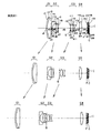
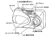
以下、本発明のズームレンズの実施例1〜8について説明する。実施例1〜8の無限遠物点合焦時の広角端(a)、中間状態(b)、望遠端(c)でのレンズ断面図をそれぞれ図1〜図8に示す。各図中、第1レンズ群はG1、第2レンズ群はG2、開口絞りはS、第3レンズ群はG3、第4レンズ群はG4、第5レンズ群はG5、光学的ローパスフィル
ターはF、電子撮像素子であるCCDのカバーガラスはC、CCDの像面はIで示してある。なお、近赤外シャープカットコートについては、例えば光学的ローパスフィルターFに直接コートを施こしてもよく、また、別に赤外カット吸収フィルターを配置してもよい。
Examples 1 to 8 of the zoom lens according to the present invention will be described below. 1 to 8 show lens cross-sectional views at the wide-angle end (a), the intermediate state (b), and the telephoto end (c) when focusing on an object point at infinity in Examples 1 to 8, respectively. In each figure, the first lens group is G1, the second lens group is G2, the aperture stop is S, the third lens group is G3, the fourth lens group is G4, the fifth lens group is G5, and the optical low-pass filter is F. The cover glass of the CCD, which is an electronic image sensor, is indicated by C, and the image plane of the CCD is indicated by I. As for the near-infrared sharp cut coat, for example, the optical low-pass filter F may be directly coated, or an infrared cut absorption filter may be separately arranged.
なお、実施例9〜16に関しては、それぞれ実施例1〜8と同様に構成されているので、図を省略する。 In addition, about Example 9-16, since it is respectively comprised similarly to Examples 1-8, a figure is abbreviate | omitted.
実施例1のズームレンズは、図1に示すように、物体側から順に、正屈折力の第1レンズ群G1、負屈折力の第2レンズ群G2、開口絞りS、正屈折力の第3レンズ群G3、正屈折力の第4レンズ群G4から構成されている。 As shown in FIG. 1, the zoom lens according to the first embodiment includes, in order from the object side, a first lens group G1 having a positive refractive power, a second lens group G2 having a negative refractive power, an aperture stop S, and a third lens having a positive refractive power. The lens unit G3 includes a fourth lens unit G4 having a positive refractive power.
広角端から望遠端への変倍をする際の移動状態を以下に示す。ここで、広角端から望遠端までの間で第2レンズ群G2、第3レンズ群G3又は第4レンズ群G4の移動方向の変化する点を中間状態とした。以下、同じ。 The movement state when zooming from the wide-angle end to the telephoto end is shown below. Here, the point in which the moving direction of the second lens group G2, the third lens group G3, or the fourth lens group G4 changes between the wide-angle end and the telephoto end is defined as an intermediate state. same as below.
第1レンズ群G1は、広角端から望遠端まで、物体側へ移動する。 The first lens group G1 moves toward the object side from the wide-angle end to the telephoto end.
第2レンズ群G2は、広角端から望遠端まで、第1レンズ群G1との間隔を広げ、第3レンズ群G3との間隔を狭めながら物体側に移動する。 The second lens group G2 moves toward the object side from the wide-angle end to the telephoto end while widening the distance from the first lens group G1 and narrowing the distance from the third lens group G3.
開口絞りSと第3レンズ群G3は、広角端から望遠端まで、一体に物体側へ移動する。 The aperture stop S and the third lens group G3 integrally move toward the object side from the wide-angle end to the telephoto end.
第4レンズ群G4は、広角端から望遠端まで、第3レンズ群G3との間隔を広げながら像側に移動する。 The fourth lens group G4 moves toward the image side from the wide-angle end to the telephoto end while increasing the distance from the third lens group G3.
物体側から順に、第1レンズ群G1は、物体側に凸面を向けた負メニスカスレンズと両凸正レンズの接合レンズからなり、第2レンズ群G2は、両凹負レンズと、像側に凸面を向けた正メニスカスレンズと両凹負レンズの接合レンズとからなり、第3レンズ群G3は、両凸正レンズと、物体側に凸面を向けた負メニスカスレンズとからなり、第4レンズ群G4は、両凸正レンズ1枚からなる。 In order from the object side, the first lens group G1 includes a cemented lens of a negative meniscus lens having a convex surface facing the object side and a biconvex positive lens, and the second lens group G2 has a biconcave negative lens and a convex surface on the image side. The third lens group G3 is composed of a biconvex positive lens and a negative meniscus lens having a convex surface directed toward the object side, and a fourth lens group G4. Consists of one biconvex positive lens.
非球面は、第1レンズ群G1の接合レンズの最も像側の面、第2レンズ群G2の両凹負レンズの両面、接合レンズの最も像側の面、第3レンズ群G3の両凸正レンズの両面、負メニスカスレンズの像側の面、第4レンズ群G4の両凸正レンズの像側の面の8面に用いている。 The aspherical surface is the most image side surface of the cemented lens of the first lens group G1, both surfaces of the biconcave negative lens of the second lens group G2, the most image side surface of the cemented lens, and the biconvex positive of the third lens group G3. It is used for 8 surfaces of both surfaces of the lens, the image side surface of the negative meniscus lens, and the image side surface of the biconvex positive lens of the fourth lens group G4.
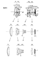
実施例2のズームレンズは、図2に示すように、物体側から順に、正屈折力の第1レンズ群G1、負屈折力の第2レンズ群G2、開口絞りS、正屈折力の第3レンズ群G3、正屈折力の第4レンズ群G4から構成されている。 As shown in FIG. 2, the zoom lens according to the second embodiment includes, in order from the object side, a first lens group G1 having a positive refractive power, a second lens group G2 having a negative refractive power, an aperture stop S, and a third lens having a positive refractive power. The lens unit G3 includes a fourth lens unit G4 having a positive refractive power.
第1レンズ群G1は、広角端から望遠端まで、物体側へ移動する。 The first lens group G1 moves toward the object side from the wide-angle end to the telephoto end.
第2レンズ群G2は、広角端から中間状態まで、第1レンズ群G1との間隔を広げ、第3レンズ群G3との間隔を狭めながら物体側に移動し、中間状態から望遠端まで、第1レンズ群G1との間隔を広げ、第3レンズ群G3との間隔を狭めながら像側に移動する。中間状態では、広角端の位置より物体側に位置し、望遠端では、広角端の位置より像側に位置する。 The second lens group G2 moves from the wide-angle end to the intermediate state toward the object side while increasing the distance from the first lens group G1 and narrowing the distance from the third lens group G3, and from the intermediate state to the telephoto end. The distance from the first lens group G1 is widened, and the distance from the third lens group G3 is narrowed to move toward the image side. In the intermediate state, it is located closer to the object side than the wide-angle end position, and at the telephoto end it is located closer to the image side than the wide-angle end position.
開口絞りSと第3レンズ群G3は、広角端から中間状態まで、第2レンズ群G2との間
隔を狭め、第4レンズ群G4との間隔を広げながら物体側に移動し、中間状態から望遠端まで、第2レンズ群G2との間隔を狭め、第4レンズ群G4との間隔を広げながら像側に移動する。中間状態では、広角端の位置より物体側に位置し、望遠端では、広角端の位置より物体側、中間状態より像側に位置する。
The aperture stop S and the third lens group G3 move toward the object side while narrowing the distance from the second lens group G2 from the wide-angle end to the intermediate state, and widening the distance from the fourth lens group G4. To the end, the distance from the second lens group G2 is narrowed, and the distance from the fourth lens group G4 is increased to move to the image side. In the intermediate state, it is located closer to the object side than the wide-angle end position, and at the telephoto end, it is located closer to the object side than the wide-angle end position and closer to the image side than the intermediate state.
第4レンズ群G4は、広角端から中間状態まで、第3レンズ群G3との間隔を広げながら物体側に移動し、中間状態から望遠端まで、第3レンズ群G3との間隔を広げながら像側に移動する。中間状態では、広角端の位置より若干物体側に位置し、望遠端では、広角端の位置より像側に位置する。 The fourth lens group G4 moves toward the object side from the wide-angle end to the intermediate state while increasing the distance from the third lens group G3, and increases the distance from the third lens group G3 from the intermediate state to the telephoto end. Move to the side. In the intermediate state, it is located slightly closer to the object side than the wide-angle end position, and at the telephoto end it is located closer to the image side than the wide-angle end position.
物体側から順に、第1レンズ群G1は、物体側に凸面を向けた負メニスカスレンズと両凸正レンズの接合レンズからなり、第2レンズ群G2は、両凹負レンズと、物体側に凸面を向けた負メニスカスレンズと物体側に凸面を向けた正メニスカスレンズの接合レンズとからなり、第3レンズ群G3は、両凸正レンズと、物体側に凸面を向けた負メニスカスレンズとからなり、第4レンズ群G4は、像側に凸面を向けた正メニスカスレンズ1枚からなる。 In order from the object side, the first lens group G1 includes a cemented lens of a negative meniscus lens having a convex surface facing the object side and a biconvex positive lens, and the second lens group G2 has a biconcave negative lens and a convex surface facing the object side. The third lens group G3 is composed of a biconvex positive lens and a negative meniscus lens having a convex surface facing the object side. The fourth lens group G4 includes one positive meniscus lens having a convex surface facing the image side.
非球面は、第1レンズ群G1の接合レンズの最も像側の面、第2レンズ群G2の両凹負レンズの両面、接合レンズの最も物体側の面、第3レンズ群G3の両凸正レンズの両面、第4レンズ群G4の正メニスカスレンズの両面の8面に用いている。 The aspherical surface is the most image side surface of the cemented lens of the first lens group G1, both surfaces of the biconcave negative lens of the second lens group G2, the most object side surface of the cemented lens, and the biconvex positive of the third lens group G3. It is used on both surfaces of the lens and on both surfaces of the positive meniscus lens of the fourth lens group G4.
実施例3のズームレンズは、図3に示すように、物体側から順に、正屈折力の第1レンズ群G1、負屈折力の第2レンズ群G2、開口絞りS、正屈折力の第3レンズ群G3、正屈折力の第4レンズ群G4から構成されている。 As shown in FIG. 3, the zoom lens of Example 3 includes, in order from the object side, a first lens group G1 having a positive refractive power, a second lens group G2 having a negative refractive power, an aperture stop S, and a third lens having a positive refractive power. The lens unit G3 includes a fourth lens unit G4 having a positive refractive power.
広角端から望遠端への変倍をする際の移動状態を以下に示す。 The movement state when zooming from the wide-angle end to the telephoto end is shown below.
第1レンズ群G1は、広角端から望遠端まで、物体側へ移動する。 The first lens group G1 moves toward the object side from the wide-angle end to the telephoto end.
第2レンズ群G2は、広角端から中間状態まで、第1レンズ群G1との間隔を広げ、第3レンズ群G3との間隔を狭めながら物体側に移動し、中間状態から望遠端まで、第1レンズ群G1との間隔を広げ、第3レンズ群G3との間隔を狭めながら像側に移動する。中間状態では、広角端の位置より若干物体側に位置し、望遠端では、広角端の位置より像側に位置する。 The second lens group G2 moves from the wide-angle end to the intermediate state toward the object side while increasing the distance from the first lens group G1 and narrowing the distance from the third lens group G3, and from the intermediate state to the telephoto end. The distance from the first lens group G1 is widened, and the distance from the third lens group G3 is narrowed to move toward the image side. In the intermediate state, it is located slightly closer to the object side than the wide-angle end position, and at the telephoto end it is located closer to the image side than the wide-angle end position.
開口絞りSと第3レンズ群G3は、広角端から望遠端まで、第2レンズ群G2との間隔を狭め、第4レンズ群G4との間隔を広げながら物体側に移動する。 The aperture stop S and the third lens group G3 move toward the object side from the wide-angle end to the telephoto end while narrowing the distance from the second lens group G2 and widening the distance from the fourth lens group G4.
第4レンズ群G4は、広角端から望遠端まで、第3レンズ群G3との間隔を広げながら像側に移動する。 The fourth lens group G4 moves toward the image side from the wide-angle end to the telephoto end while increasing the distance from the third lens group G3.
物体側から順に、第1レンズ群G1は、物体側に凸面を向けた負メニスカスレンズと両凸正レンズの接合レンズからなり、第2レンズ群G2は、両凹負レンズと、像側に凸面を向けた正メニスカスレンズと両凹負レンズの接合レンズとからなり、第3レンズ群G3は、両凸正レンズと、物体側に凸面を向けた正メニスカスレンズと物体側に凸面を向けた負メニスカスレンズの接合レンズとからなり、第4レンズ群G4は、両凸正レンズ1枚からなる。 In order from the object side, the first lens group G1 includes a cemented lens of a negative meniscus lens having a convex surface facing the object side and a biconvex positive lens, and the second lens group G2 has a biconcave negative lens and a convex surface on the image side. The third lens group G3 includes a biconvex positive lens, a positive meniscus lens having a convex surface directed toward the object side, and a negative lens having a convex surface directed toward the object side. The fourth lens group G4 is composed of a single biconvex positive lens.
非球面は、第1レンズ群G1の接合レンズの最も像側の面、第2レンズ群G2の両凹負レンズの両面、接合レンズの最も像側の面、第3レンズ群G3の両凸正レンズの両面、第
4レンズ群G4の両凸正レンズの両面の8面に用いている。
The aspherical surface is the most image side surface of the cemented lens of the first lens group G1, both surfaces of the biconcave negative lens of the second lens group G2, the most image side surface of the cemented lens, and the biconvex positive of the third lens group G3. It is used on both surfaces of the lens and on both surfaces of the biconvex positive lens of the fourth lens group G4.
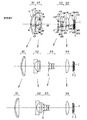
実施例4のズームレンズは、図4に示すように、物体側から順に、正屈折力の第1レンズ群G1、負屈折力の第2レンズ群G2、開口絞りS、正屈折力の第3レンズ群G3、正屈折力の第4レンズ群G4から構成されている。 As shown in FIG. 4, the zoom lens of Example 4 includes, in order from the object side, a first lens group G1 having a positive refractive power, a second lens group G2 having a negative refractive power, an aperture stop S, and a third lens having a positive refractive power. The lens unit G3 includes a fourth lens unit G4 having a positive refractive power.
広角端から望遠端への変倍をする際の移動状態を以下に示す。 The movement state when zooming from the wide-angle end to the telephoto end is shown below.
第1レンズ群G1は、広角端から望遠端まで、物体側へ移動する。 The first lens group G1 moves toward the object side from the wide-angle end to the telephoto end.
第2レンズ群G2は、広角端から中間状態まで、第1レンズ群G1との間隔を広げ、第3レンズ群G3との間隔を狭めながら物体側に移動し、中間状態から望遠端まで、第1レンズ群G1との間隔を広げ、第3レンズ群G3との間隔を狭めながら像側に移動する。中間状態では、広角端の位置より若干物体側に位置し、望遠端では、広角端の位置より若干像側に位置する。 The second lens group G2 moves from the wide-angle end to the intermediate state toward the object side while increasing the distance from the first lens group G1 and narrowing the distance from the third lens group G3, and from the intermediate state to the telephoto end. The distance from the first lens group G1 is widened, and the distance from the third lens group G3 is narrowed to move toward the image side. In the intermediate state, it is located slightly closer to the object side than the wide-angle end position, and at the telephoto end it is located slightly closer to the image side than the wide-angle end position.
開口絞りSと第3レンズ群G3は、広角端から望遠端まで、第2レンズ群G2との間隔を狭め、第4レンズ群G4との間隔を広げながら物体側に移動する。 The aperture stop S and the third lens group G3 move toward the object side from the wide-angle end to the telephoto end while narrowing the distance from the second lens group G2 and widening the distance from the fourth lens group G4.
第4レンズ群G4は、広角端から望遠端まで、第3レンズ群G3との間隔を広げながら像側に移動する。 The fourth lens group G4 moves toward the image side from the wide-angle end to the telephoto end while increasing the distance from the third lens group G3.
物体側から順に、第1レンズ群G1は、物体側に凸面を向けた負メニスカスレンズと両凸正レンズの接合レンズからなり、第2レンズ群G2は、両凹負レンズと、像側に凸面を向けた正メニスカスレンズと両凹負レンズの接合レンズとからなり、第3レンズ群G3は、両凸正レンズと、物体側に凸面を向けた正メニスカスレンズと物体側に凸面を向けた負メニスカスレンズの接合レンズとからなり、第4レンズ群G4は、両凸正レンズ1枚からなる。 In order from the object side, the first lens group G1 includes a cemented lens of a negative meniscus lens having a convex surface facing the object side and a biconvex positive lens, and the second lens group G2 has a biconcave negative lens and a convex surface on the image side. The third lens group G3 includes a biconvex positive lens, a positive meniscus lens having a convex surface directed toward the object side, and a negative lens having a convex surface directed toward the object side. The fourth lens group G4 is composed of a single biconvex positive lens.
非球面は、第1レンズ群G1の接合レンズの最も像側の面、第2レンズ群G2の両凹負レンズの両面、接合レンズの最も像側の面、第3レンズ群G3の両凸正レンズの両面、第4レンズ群G4の両凸正レンズの両面の8面に用いている。 The aspherical surface is the most image side surface of the cemented lens of the first lens group G1, both surfaces of the biconcave negative lens of the second lens group G2, the most image side surface of the cemented lens, and the biconvex positive of the third lens group G3. It is used on both surfaces of the lens and on both surfaces of the biconvex positive lens of the fourth lens group G4.
実施例5のズームレンズは、図5に示すように、物体側から順に、正屈折力の第1レンズ群G1、負屈折力の第2レンズ群G2、開口絞りS、正屈折力の第3レンズ群G3、正屈折力の第4レンズ群G4から構成されている。 As shown in FIG. 5, the zoom lens of Example 5 includes, in order from the object side, a first lens group G1 having a positive refractive power, a second lens group G2 having a negative refractive power, an aperture stop S, and a third lens having a positive refractive power. The lens unit G3 includes a fourth lens unit G4 having a positive refractive power.
広角端から望遠端への変倍をする際の移動状態を以下に示す。 The movement state when zooming from the wide-angle end to the telephoto end is shown below.
第1レンズ群G1は、広角端から望遠端まで、物体側へ移動する。 The first lens group G1 moves toward the object side from the wide-angle end to the telephoto end.
第2レンズ群G2は、広角端から中間状態まで、第1レンズ群G1との間隔を広げ、第3レンズ群G3との間隔を狭めながら物体側に移動し、中間状態から望遠端まで、第1レンズ群G1との間隔を広げ、第3レンズ群G3との間隔を狭めながら像側に移動する。中間状態では、広角端の位置より若干物体側に位置し、望遠端では、広角端の位置より像側に位置する。 The second lens group G2 moves from the wide-angle end to the intermediate state toward the object side while increasing the distance from the first lens group G1 and narrowing the distance from the third lens group G3, and from the intermediate state to the telephoto end. The distance from the first lens group G1 is widened, and the distance from the third lens group G3 is narrowed to move toward the image side. In the intermediate state, it is located slightly closer to the object side than the wide-angle end position, and at the telephoto end it is located closer to the image side than the wide-angle end position.
開口絞りSと第3レンズ群G3は、広角端から望遠端まで、第2レンズ群G2との間隔を狭め、第4レンズ群G4との間隔を広げながら物体側に移動する。 The aperture stop S and the third lens group G3 move toward the object side from the wide-angle end to the telephoto end while narrowing the distance from the second lens group G2 and widening the distance from the fourth lens group G4.
第4レンズ群G4は、広角端から中間状態まで、第3レンズ群G3との間隔を広げながら像側に移動し、中間状態から望遠端まで、第3レンズ群G3との間隔を広げながら物体側に移動する。中間状態では、広角端の位置より像側に位置し、望遠端では、広角端の位置より若干像側、中間状態の位置より若干物体側に位置する。 The fourth lens group G4 moves toward the image side from the wide-angle end to the intermediate state while increasing the distance from the third lens group G3, and increases the distance from the third lens group G3 from the intermediate state to the telephoto end. Move to the side. In the intermediate state, it is positioned on the image side from the position at the wide-angle end, and at the telephoto end, it is positioned slightly on the image side from the position at the wide-angle end and slightly on the object side from the position in the intermediate state.
物体側から順に、第1レンズ群G1は、物体側に凸面を向けた負メニスカスレンズと両凸正レンズの接合レンズからなり、第2レンズ群G2は、両凹負レンズと、像側に凸面を向けた正メニスカスレンズと両凹負レンズの接合レンズとからなり、第3レンズ群G3は、両凸正レンズと、両凸正レンズと両凹負レンズの接合レンズとからなり、第4レンズ群G4は、両凸正レンズ1枚からなる。 In order from the object side, the first lens group G1 includes a cemented lens of a negative meniscus lens having a convex surface facing the object side and a biconvex positive lens, and the second lens group G2 has a biconcave negative lens and a convex surface on the image side. The third lens group G3 is composed of a biconvex positive lens, a biconvex positive lens and a biconcave negative lens cemented lens, and a fourth lens. The group G4 is composed of one biconvex positive lens.
非球面は、第1レンズ群G1の接合レンズの最も像側の面、第2レンズ群G2の両凹負レンズの両面、接合レンズの最も像側の面、第3レンズ群G3の両凸正レンズの両面、第4レンズ群G4の両凸正レンズの両面の8面に用いている。 The aspherical surface is the most image side surface of the cemented lens of the first lens group G1, both surfaces of the biconcave negative lens of the second lens group G2, the most image side surface of the cemented lens, and the biconvex positive of the third lens group G3. It is used on both surfaces of the lens and on both surfaces of the biconvex positive lens of the fourth lens group G4.
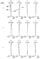
実施例6のズームレンズは、図6に示すように、物体側から順に、正屈折力の第1レンズ群G1、負屈折力の第2レンズ群G2、開口絞りS、正屈折力の第3レンズ群G3、正屈折力の第4レンズ群G4から構成されている。 As shown in FIG. 6, the zoom lens of Example 6 includes, in order from the object side, a first lens group G1 having a positive refractive power, a second lens group G2 having a negative refractive power, an aperture stop S, and a third lens having a positive refractive power. The lens unit G3 includes a fourth lens unit G4 having a positive refractive power.
広角端から望遠端への変倍をする際の移動状態を以下に示す。 The movement state when zooming from the wide-angle end to the telephoto end is shown below.
第1レンズ群G1は、広角端から望遠端まで、物体側へ移動する。 The first lens group G1 moves toward the object side from the wide-angle end to the telephoto end.
第2レンズ群G2は、広角端から中間状態まで、第1レンズ群G1との間隔を広げ、第3レンズ群G3との間隔を狭めながら物体側に移動し、中間状態から望遠端まで、第1レンズ群G1との間隔を広げ、第3レンズ群G3との間隔を狭めながら像側に移動する。中間状態では、広角端の位置より若干物体側に位置し、望遠端では、広角端の位置より若干像側に位置する。
開口絞りSと第3レンズ群G3は、広角端から望遠端まで、第2レンズ群G2との間隔を狭め、第4レンズ群G4との間隔を広げながら物体側に移動する。
The second lens group G2 moves from the wide-angle end to the intermediate state toward the object side while increasing the distance from the first lens group G1 and narrowing the distance from the third lens group G3, and from the intermediate state to the telephoto end. The distance from the first lens group G1 is widened, and the distance from the third lens group G3 is narrowed to move toward the image side. In the intermediate state, it is located slightly closer to the object side than the wide-angle end position, and at the telephoto end it is located slightly closer to the image side than the wide-angle end position.
The aperture stop S and the third lens group G3 move toward the object side from the wide-angle end to the telephoto end while narrowing the distance from the second lens group G2 and widening the distance from the fourth lens group G4.
第4レンズ群G4は、広角端から望遠端まで、第3レンズ群G3との間隔を広げながら像側に移動する。 The fourth lens group G4 moves toward the image side from the wide-angle end to the telephoto end while increasing the distance from the third lens group G3.
物体側から順に、第1レンズ群G1は、物体側に凸面を向けた負メニスカスレンズと、両凸正レンズとからなり、第2レンズ群G2は、両凹負レンズと、像側に凸面を向けた正メニスカスレンズと両凹負レンズの接合レンズとからなり、第3レンズ群G3は、両凸正レンズと、物体側に凸面を向けた正メニスカスレンズと物体側に凸面を向けた負メニスカスレンズの接合レンズとからなり、第4レンズ群G4は、両凸正レンズ1枚からなる。 In order from the object side, the first lens group G1 includes a negative meniscus lens having a convex surface facing the object side and a biconvex positive lens, and the second lens group G2 has a biconcave negative lens and a convex surface on the image side. The third lens group G3 includes a biconvex positive lens, a positive meniscus lens having a convex surface facing the object side, and a negative meniscus having a convex surface facing the object side. The fourth lens group G4 is composed of one biconvex positive lens.
非球面は、第1レンズ群G1の両凸正レンズの像側の面、第2レンズ群G2の両凹負レンズの両面、接合レンズの最も像側の面、第3レンズ群G3の両凸正レンズの両面、第4レンズ群G4の両凸正レンズの両面の8面に用いている。 The aspherical surfaces are the image-side surface of the biconvex positive lens of the first lens group G1, the both surfaces of the biconcave negative lens of the second lens group G2, the most image-side surface of the cemented lens, and the biconvex of the third lens group G3. It is used on both surfaces of the positive lens and on both surfaces of the biconvex positive lens of the fourth lens group G4.
実施例7のズームレンズは、図7に示すように、物体側から順に、正屈折力の第1レンズ群G1、負屈折力の第2レンズ群G2、開口絞りS、正屈折力の第3レンズ群G3、正屈折力の第4レンズ群G4から構成されている。 As shown in FIG. 7, the zoom lens according to the seventh exemplary embodiment includes, in order from the object side, a first lens group G1 having a positive refractive power, a second lens group G2 having a negative refractive power, an aperture stop S, and a third lens having a positive refractive power. The lens unit G3 includes a fourth lens unit G4 having a positive refractive power.
広角端から望遠端への変倍をする際の移動状態を以下に示す。 The movement state when zooming from the wide-angle end to the telephoto end is shown below.
第1レンズ群G1は、広角端から望遠端まで、物体側へ移動する。 The first lens group G1 moves toward the object side from the wide-angle end to the telephoto end.
第2レンズ群G2は、広角端から中間状態まで、第1レンズ群G1との間隔を広げ、第3レンズ群G3との間隔を狭めながら物体側に移動し、中間状態から望遠端まで、第1レンズ群G1との間隔を広げ、第3レンズ群G3との間隔を狭めながら像側に移動する。中間状態では、広角端の位置より若干物体側に位置し、望遠端では、広角端の位置より若干像側に位置する。 The second lens group G2 moves from the wide-angle end to the intermediate state toward the object side while increasing the distance from the first lens group G1 and narrowing the distance from the third lens group G3, and from the intermediate state to the telephoto end. The distance from the first lens group G1 is widened, and the distance from the third lens group G3 is narrowed to move toward the image side. In the intermediate state, it is located slightly closer to the object side than the wide-angle end position, and at the telephoto end it is located slightly closer to the image side than the wide-angle end position.
開口絞りSと第3レンズ群G3は、広角端から望遠端まで、第2レンズ群G2との間隔を狭め、第4レンズ群G4との間隔を広げながら物体側に移動する。 The aperture stop S and the third lens group G3 move toward the object side from the wide-angle end to the telephoto end while narrowing the distance from the second lens group G2 and widening the distance from the fourth lens group G4.
第4レンズ群G4は、広角端から望遠端まで、第3レンズ群G3との間隔を広げながら像側に移動する。 The fourth lens group G4 moves toward the image side from the wide-angle end to the telephoto end while increasing the distance from the third lens group G3.
物体側から順に、第1レンズ群G1は、物体側に凸面を向けた負メニスカスレンズと両凸正レンズの接合レンズからなり、第2レンズ群G2は、両凹負レンズと、像側に凸面を向けた正メニスカスレンズと、両凹負レンズとからなり、第3レンズ群G3は、両凸正レンズと、物体側に凸面を向けた正メニスカスレンズと物体側に凸面を向けた負メニスカスレンズの接合レンズとからなり、第4レンズ群G4は、両凸正レンズ1枚からなる。 In order from the object side, the first lens group G1 includes a cemented lens of a negative meniscus lens having a convex surface facing the object side and a biconvex positive lens, and the second lens group G2 has a biconcave negative lens and a convex surface on the image side. The third lens group G3 includes a biconvex positive lens, a positive meniscus lens having a convex surface directed toward the object side, and a negative meniscus lens having a convex surface directed toward the object side. The fourth lens group G4 is composed of one biconvex positive lens.
非球面は、第1レンズ群G1の接合レンズの最も像側の面、第2レンズ群G2の像側の両凹負レンズの両面、物体側の両凹負レンズの像側の面、第3レンズ群G3の両凸正レンズの両面、第4レンズ群G4の両凸正レンズの両面の8面に用いている。 The aspherical surface is the most image side surface of the cemented lens of the first lens group G1, both surfaces of the image side biconcave negative lens of the second lens group G2, the image side surface of the object side biconcave negative lens, and the third surface. It is used on both sides of the biconvex positive lens of the lens group G3 and on both sides of the biconvex positive lens of the fourth lens group G4.
実施例8のズームレンズは、図8に示すように、物体側から順に、正屈折力の第1レンズ群G1、負屈折力の第2レンズ群G2、開口絞りS、正屈折力の第3レンズ群G3、正屈折力の第4レンズ群G4から構成されている。 As shown in FIG. 8, the zoom lens according to the eighth embodiment includes, in order from the object side, a first lens group G1 having a positive refractive power, a second lens group G2 having a negative refractive power, an aperture stop S, and a third lens having a positive refractive power. The lens unit G3 includes a fourth lens unit G4 having a positive refractive power.
広角端から望遠端への変倍をする際の移動状態を以下に示す。 The movement state when zooming from the wide-angle end to the telephoto end is shown below.
第1レンズ群G1は、広角端から望遠端まで、物体側へ移動する。 The first lens group G1 moves toward the object side from the wide-angle end to the telephoto end.
第2レンズ群G2は、広角端から中間状態まで、第1レンズ群G1との間隔を広げ、第3レンズ群G3との間隔を狭めながら物体側に移動し、中間状態から望遠端まで、第1レンズ群G1との間隔を広げ、第3レンズ群G3との間隔を狭めながら像側に移動する。中間状態では、広角端の位置より若干物体側に位置し、望遠端では、広角端の位置より若干像側に位置する。 The second lens group G2 moves from the wide-angle end to the intermediate state toward the object side while increasing the distance from the first lens group G1 and narrowing the distance from the third lens group G3, and from the intermediate state to the telephoto end. The distance from the first lens group G1 is widened, and the distance from the third lens group G3 is narrowed to move toward the image side. In the intermediate state, it is located slightly closer to the object side than the wide-angle end position, and at the telephoto end it is located slightly closer to the image side than the wide-angle end position.
開口絞りSと第3レンズ群G3は、広角端から望遠端まで、第2レンズ群G2との間隔を狭め、第4レンズ群G4との間隔を広げながら物体側に移動する。 The aperture stop S and the third lens group G3 move toward the object side from the wide-angle end to the telephoto end while narrowing the distance from the second lens group G2 and widening the distance from the fourth lens group G4.
第4レンズ群G4は、広角端から望遠端まで、第3レンズ群G3との間隔を広げながら像側に移動する。 The fourth lens group G4 moves toward the image side from the wide-angle end to the telephoto end while increasing the distance from the third lens group G3.
物体側から順に、第1レンズ群G1は、物体側に凸面を向けた負メニスカスレンズと、両凸正レンズとからなり、第2レンズ群G2は、両凹負レンズと、像側に凸面を向けた正メニスカスレンズと、両凹負レンズとからなり、第3レンズ群G3は、両凸正レンズと、物体側に凸面を向けた正メニスカスレンズと物体側に凸面を向けた負メニスカスレンズの接合レンズとからなり、第4レンズ群G4は、両凸正レンズ1枚からなる。 In order from the object side, the first lens group G1 includes a negative meniscus lens having a convex surface facing the object side and a biconvex positive lens, and the second lens group G2 has a biconcave negative lens and a convex surface on the image side. The third lens group G3 includes a biconvex positive lens, a positive meniscus lens having a convex surface facing the object side, and a negative meniscus lens having a convex surface facing the object side. The fourth lens group G4 includes a cemented lens, and includes one biconvex positive lens.
非球面は、第1レンズ群G1の接合レンズの最も像側の面、第2レンズ群G2の像側の両凹負レンズの両面、物体側の両凹負レンズの像側の面、第3レンズ群G3の両凸正レンズの両面、第4レンズ群G4の両凸正レンズの両面の8面に用いている。 The aspherical surface is the most image side surface of the cemented lens of the first lens group G1, both surfaces of the image side biconcave negative lens of the second lens group G2, the image side surface of the object side biconcave negative lens, and the third surface. It is used on both sides of the biconvex positive lens of the lens group G3 and on both sides of the biconvex positive lens of the fourth lens group G4.
以下、各実施例におけるレンズの数値データを示す。 The numerical data of the lens in each example is shown below.
なお、実施例11〜20に関しては、それぞれ実施例1〜10と同様に構成されており、各種データのみを示す。 In addition, about Examples 11-20, it is comprised similarly to Examples 1-10, respectively, and shows only various data.
各実施例におけるレンズの数値データにおいては、rは各レンズ面の曲率半径、dは各レンズの肉厚または間隔、ndは各レンズのd線における屈折率、νdは各レンズのd線におけるアッベ数、Kは円錐係数、A4、A6、A8、A10は非球面係数、E±nは×10±nをそ
れぞれ示している。
In the numerical data of the lens in each embodiment, r is the radius of curvature of each lens surface, d is the thickness or spacing of each lens, nd is the refractive index at the d-line of each lens, and νd is the Abbe at the d-line of each lens. Number, K is a conical coefficient, A4, A6, A8, and A10 are aspheric coefficients, and E ± n is × 10 ± n .
また、各非球面形状は、各実施例における各非球面係数を用いて、以下の式で表される。
Z=(Y2/r)/[1+{1−(1+K)・(Y/r)2}1/2]
+A4×Y4+A6×Y6+A8×Y8+A10×Y10
ただし、光軸方向の座標をZ、光軸と垂直な方向の座標をYとする。
Each aspheric shape is expressed by the following expression using each aspheric coefficient in each embodiment.
Z = (Y 2 / r) / [1+ {1− (1 + K) · (Y / r) 2 } 1/2 ]
+ A4 × Y 4 + A6 × Y 6 + A8 × Y 8 + A10 × Y 10
However, the coordinate in the optical axis direction is Z, and the coordinate in the direction perpendicular to the optical axis is Y.
数値実施例1
単位 mm
面データ
面番号 r d nd νd
1 26.666 0.80 1.92286 18.90
2 19.250 3.50 1.74320 49.34
3(非球面) -176.734 可変
4(非球面) -40.959 0.80 1.80610 40.92
5(非球面) 5.528 2.69
6 -1141.838 1.71 1.94595 17.98
7 -10.862 0.70 1.80610 40.92
8(非球面) 134.158 可変
9(絞り) ∞ 0.30
10(非球面) 4.298 2.40 1.49700 81.54
11(非球面) -11.697 0.10
12 8.062 1.30 2.00170 20.64
13(非球面) 4.214 可変
14 40.803 2.20 1.74320 49.34
15(非球面) -16.732 可変
16 ∞ 0.40 1.54771 62.84
17 ∞ 0.50
18 ∞ 0.50 1.51633 64.14
19 ∞ 0.37
像面 ∞
非球面データ
第3面
K=0.000,A4=7.63091E-06,A6=-4.82260E-09
第4面
K=0.000,A4=1.32148E-03,A6=-5.72963E-05,A8=1.18744E-06,A10=-1.03698E-08
第5面
K=0.000,A4=1.61134E-03,A6=2.28101E-05,A8=-1.71055E-06,A10=-1.22624E-09
第8面
K=0.000,A4=-4.56444E-04,A6=-9.41345E-06,A8=-1.00141E-07,A10=-2.44141E-10
第10面
K=0.000,A4=-1.33244E-03,A6=-5.69354E-05,A8=-2.91994E-06,A10=-7.27923E-08
第11面
K=0.000,A4=-1.85420E-05,A6=-2.18626E-05,A8=1.44977E-06,A10=-2.94845E-08
第13面
K=0.000,A4=1.21796E-03,A6=9.52243E-05
第15面
K=0.000,A4=3.00000E-05
各種データ
ズーム比 2.87
広角 中間 望遠
焦点距離 5.07 14.80 48.79
Fナンバー 3.50 5.24 6.00
画角 77.72 28.31 9.15
像高 3.88 3.88 3.88
レンズ全長 37.84 50.08 64.46
BF 6.46 6.06 4.38
d3 0.59 9.44 16.89
d9 10.35 4.89 0.73
d11 3.95 13.20 25.96
d13 4.97 4.57 2.91
ズームレンズ群データ
群 始面 焦点距離
1 1 34.03
2 5 -6.36
3 10 10.21
4 12 16.15
Numerical example 1
Unit mm
Surface data surface number r d nd νd
1 26.666 0.80 1.92286 18.90
2 19.250 3.50 1.74320 49.34
3 (Aspherical) -176.734 Variable
4 (Aspherical surface) -40.959 0.80 1.80610 40.92
5 (Aspherical) 5.528 2.69
6 -1141.838 1.71 1.94595 17.98
7 -10.862 0.70 1.80610 40.92
8 (Aspherical) 134.158 Variable
9 (Aperture) ∞ 0.30
10 (Aspherical surface) 4.298 2.40 1.49700 81.54
11 (Aspherical surface) -11.697 0.10
12 8.062 1.30 2.00170 20.64
13 (Aspherical) 4.214 Variable
14 40.803 2.20 1.74320 49.34
15 (Aspherical) -16.732 Variable
16 ∞ 0.40 1.54771 62.84
17 ∞ 0.50
18 ∞ 0.50 1.51633 64.14
19 ∞ 0.37
Image plane ∞
Aspheric data 3rd surface
K = 0.000, A4 = 7.63091E-06, A6 = -4.82260E-09
4th page
K = 0.000, A4 = 1.32148E-03, A6 = -5.72963E-05, A8 = 1.18744E-06, A10 = -1.03698E-08
5th page
K = 0.000, A4 = 1.61134E-03, A6 = 2.28101E-05, A8 = -1.71055E-06, A10 = -1.22624E-09
8th page
K = 0.000, A4 = -4.56444E-04, A6 = -9.41345E-06, A8 = -1.00141E-07, A10 = -2.44141E-10
10th page
K = 0.000, A4 = -1.33244E-03, A6 = -5.69354E-05, A8 = -2.91994E-06, A10 = -7.27923E-08
11th page
K = 0.000, A4 = -1.85420E-05, A6 = -2.18626E-05, A8 = 1.44977E-06, A10 = -2.94845E-08
13th page
K = 0.000, A4 = 1.21796E-03, A6 = 9.52243E-05
15th page
K = 0.000, A4 = 3.00000E-05
Various data Zoom ratio 2.87
Wide angle Medium telephoto Focal length 5.07 14.80 48.79
F number 3.50 5.24 6.00
Angle of view 77.72 28.31 9.15
Image height 3.88 3.88 3.88
Total lens length 37.84 50.08 64.46
BF 6.46 6.06 4.38
d3 0.59 9.44 16.89
d9 10.35 4.89 0.73
d11 3.95 13.20 25.96
d13 4.97 4.57 2.91
Zoom lens group data Group Start surface Focal length
1 1 34.03
2 5 -6.36
3 10 10.21
4 12 16.15
数値実施例2
単位 mm
面データ
面番号 r d nd νd
1 16.468 0.60 1.94595 17.98
2 11.669 4.00 1.77250 49.60
3(非球面) -298.514 可変
4(非球面) -35.694 0.50 1.83481 42.71
5(非球面) 5.250 1.50
6(非球面) 41.185 0.50 1.77250 49.60
7 6.700 1.60 1.94595 17.98
8 21.527 可変
9(絞り) ∞ 0.30
10(非球面) 4.099 2.05 1.49700 81.54
11(非球面) -10.634 0.10
12 4.996 0.40 2.00170 20.64
13 3.471 可変
14(非球面) -10.082 1.60 1.74320 49.34
15(非球面) -5.932 可変
16 ∞ 0.30 1.54771 62.84
17 ∞ 0.30
18 ∞ 0.30 1.51633 64.14
19 ∞ 0.37
像面 ∞
非球面データ
第3面
K=0.000,A4=2.79166E-05,A6=-9.61223E-08
第4面
K=0.000,A4=6.02597E-04,A6=-3.67937E-05,A8=9.10591E-07,A10=-7.79624E-09
第5面
K=0.000,A4=6.24667E-04,A6=6.02647E-05,A8=-2.20783E-06,A10=-1.71665E-08
第6面
K=0.000,A4=9.33860E-04,A6=3.93633E-05
第10面
K=0.000,A4=-2.44420E-03,A6=-1.76979E-05,A8=-3.79600E-06,A10=-7.36605E-08
第11面
K=0.000,A4=1.98650E-04,A6=-4.57669E-05,A8=2.54073E-06,A10=-2.62988E-08
第14面
K=0.000,A4=1.16049E-03,A6=-2.06578E-05
第15面
K=0.000,A4=1.54681E-03,A6=-7.33550E-07
各種データ
ズーム比 2.87
広角 中間 望遠
焦点距離 5.10 14.24 48.56
Fナンバー 6.01 8.67 11.00
画角 77.92 27.89 9.39
像高 3.88 3.88 3.88
レンズ全長 32.91 40.53 41.14
BF 8.49 8.93 1.13
d3 0.30 4.73 11.21
d8 9.19 3.81 0.30
d13 1.77 9.91 15.36
d15 7.40 7.89 0.13
ズームレンズ群データ
群 始面 焦点距離
1 1 22.14
2 5 -5.32
3 10 9.37
4 12 16.56
Numerical example 2
Unit mm
Surface data surface number r d nd νd
1 16.468 0.60 1.94595 17.98
2 11.669 4.00 1.77250 49.60
3 (Aspherical) -298.514 Variable
4 (Aspherical surface) -35.694 0.50 1.83481 42.71
5 (Aspherical surface) 5.250 1.50
6 (Aspherical surface) 41.185 0.50 1.77250 49.60
7 6.700 1.60 1.94595 17.98
8 21.527 Variable
9 (Aperture) ∞ 0.30
10 (Aspherical) 4.099 2.05 1.49700 81.54
11 (Aspherical surface) -10.634 0.10
12 4.996 0.40 2.00170 20.64
13 3.471 Variable
14 (Aspherical surface) -10.082 1.60 1.74320 49.34
15 (Aspherical) -5.932 Variable
16 ∞ 0.30 1.54771 62.84
17 ∞ 0.30
18 ∞ 0.30 1.51633 64.14
19 ∞ 0.37
Image plane ∞
Aspheric data 3rd surface
K = 0.000, A4 = 2.79166E-05, A6 = -9.61223E-08
4th page
K = 0.000, A4 = 6.02597E-04, A6 = -3.67937E-05, A8 = 9.10591E-07, A10 = -7.79624E-09
5th page
K = 0.000, A4 = 6.24667E-04, A6 = 6.02647E-05, A8 = -2.20783E-06, A10 = -1.71665E-08
6th page
K = 0.000, A4 = 9.33860E-04, A6 = 3.93633E-05
10th page
K = 0.000, A4 = -2.44420E-03, A6 = -1.76979E-05, A8 = -3.79600E-06, A10 = -7.36605E-08
11th page
K = 0.000, A4 = 1.98650E-04, A6 = -4.57669E-05, A8 = 2.54073E-06, A10 = -2.62988E-08
14th page
K = 0.000, A4 = 1.16049E-03, A6 = -2.06578E-05
15th page
K = 0.000, A4 = 1.54681E-03, A6 = -7.33550E-07
Various data Zoom ratio 2.87
Wide angle Medium telephoto Focal length 5.10 14.24 48.56
F number 6.01 8.67 11.00
Angle of view 77.92 27.89 9.39
Image height 3.88 3.88 3.88
Total lens length 32.91 40.53 41.14
BF 8.49 8.93 1.13
d3 0.30 4.73 11.21
d8 9.19 3.81 0.30
d13 1.77 9.91 15.36
d15 7.40 7.89 0.13
Zoom lens group data Group Start surface Focal length
1 1 22.14
2 5 -5.32
3 10 9.37
4 12 16.56
数値実施例3
単位 mm
面データ
面番号 r d nd νd
1 20.909 0.80 2.00170 20.64
2 16.720 3.62 1.61881 63.85
3(非球面) -99.283 可変
4(非球面) -76.528 0.80 1.83481 42.71
5(非球面) 7.133 2.58
6 -206.923 1.63 2.10225 16.79
7 -18.640 0.80 1.83481 42.71
8(非球面) 54.142 可変
9(絞り) ∞ 0.30
10(非球面) 5.593 2.49 1.69350 53.21
11(非球面) -19.473 0.08
12 5.572 1.46 1.49700 81.54
13 37.089 0.71 2.00330 28.27
14 3.573 可変
15(非球面) 32.825 3.00 1.74330 49.33
16(非球面) -14.479 可変
17 ∞ 0.40 1.54771 62.84
18 ∞ 0.50
19 ∞ 0.50 1.51633 64.14
20 ∞ 0.37
像面 ∞
非球面データ
第3面
K=0.000,A4=1.14689E-05,A6=4.83606E-09,A8=-2.02752E-10,A10=7.85884E-13
第4面
K=9.178,A4=8.86386E-05,A6=-2.97753E-06,A8=4.62415E-08,A10=-3.04205E-10
第5面
K=0.265,A4=1.50448E-04,A6=6.43712E-06,A8=-2.33528E-07,A10=-2.66160E-09
第8面
K=-1.493,A4=-3.07535E-04,A6=-4.47187E-06,A8=2.37774E-07,A10=-5.43727E-09
第10面
K=0.822,A4=-1.07173E-03,A6=-3.12892E-05,A8=-1.48549E-06,A10=-1.40758E-08
第11面
K=-3.282,A4=4.48842E-04,A6=3.09551E-06,A8=-8.51889E-07,A10=1.92356E-07
第15面
K=0.000,A4=3.25911E-05,A6=1.49778E-07
第16面
K=0.000,A4=1.36486E-04,A6=-4.26236E-06,A8=7.39509E-08
各種データ
ズーム比 2.87
広角 中間 望遠
焦点距離 5.14 15.85 49.07
Fナンバー 3.22 4.92 6.00
画角 80.40 26.86 9.00
像高 3.88 3.88 3.88
レンズ全長 42.87 51.96 57.58
BF 5.44 5.15 4.75
d3 0.18 8.37 16.20
d8 16.03 8.55 1.75
d14 2.97 11.62 16.62
d16 3.93 3.71 3.30
ズームレンズ群データ
群 始面 焦点距離
1 1 32.05
2 5 -7.25
3 10 10.94
4 12 13.89
Numerical Example 3
Unit mm
Surface data surface number r d nd νd
1 20.909 0.80 2.00170 20.64
2 16.720 3.62 1.61881 63.85
3 (Aspherical) -99.283 Variable
4 (Aspherical surface) -76.528 0.80 1.83481 42.71
5 (Aspherical surface) 7.133 2.58
6 -206.923 1.63 2.10225 16.79
7 -18.640 0.80 1.83481 42.71
8 (Aspherical) 54.142 Variable
9 (Aperture) ∞ 0.30
10 (Aspherical surface) 5.593 2.49 1.69350 53.21
11 (Aspherical surface) -19.473 0.08
12 5.572 1.46 1.49700 81.54
13 37.089 0.71 2.00330 28.27
14 3.573 Variable
15 (Aspherical surface) 32.825 3.00 1.74330 49.33
16 (Aspherical) -14.479 Variable
17 ∞ 0.40 1.54771 62.84
18 ∞ 0.50
19 ∞ 0.50 1.51633 64.14
20 ∞ 0.37
Image plane ∞
Aspheric data 3rd surface
K = 0.000, A4 = 1.14689E-05, A6 = 4.83606E-09, A8 = -2.02752E-10, A10 = 7.85884E-13
4th page
K = 9.178, A4 = 8.86386E-05, A6 = -2.97753E-06, A8 = 4.62415E-08, A10 = -3.04205E-10
5th page
K = 0.265, A4 = 1.50448E-04, A6 = 6.43712E-06, A8 = -2.33528E-07, A10 = -2.66160E-09
8th page
K = -1.493, A4 = -3.07535E-04, A6 = -4.47187E-06, A8 = 2.37774E-07, A10 = -5.43727E-09
10th page
K = 0.822, A4 = -1.07173E-03, A6 = -3.12892E-05, A8 = -1.48549E-06, A10 = -1.40758E-08
11th page
K = -3.282, A4 = 4.48842E-04, A6 = 3.09551E-06, A8 = -8.51889E-07, A10 = 1.92356E-07
15th page
K = 0.000, A4 = 3.25911E-05, A6 = 1.49778E-07
16th page
K = 0.000, A4 = 1.36486E-04, A6 = -4.26236E-06, A8 = 7.39509E-08
Various data Zoom ratio 2.87
Wide angle Medium telephoto Focal length 5.14 15.85 49.07
F number 3.22 4.92 6.00
Angle of view 80.40 26.86 9.00
Image height 3.88 3.88 3.88
Total lens length 42.87 51.96 57.58
BF 5.44 5.15 4.75
d3 0.18 8.37 16.20
d8 16.03 8.55 1.75
d14 2.97 11.62 16.62
d16 3.93 3.71 3.30
Zoom lens group data Group Start surface Focal length
1 1 32.05
2 5 -7.25
3 10 10.94
4 12 13.89
数値実施例4
単位 mm
面データ
面番号 r d nd νd
1 20.015 0.80 2.00170 20.64
2 16.318 3.62 1.59201 67.02
3(非球面) -95.128 可変
4(非球面) -72.309 0.80 1.83481 42.71
5(非球面) 7.089 2.58
6 -222.779 1.64 2.10225 16.79
7 -18.442 0.80 1.83481 42.71
8(非球面) 56.401 可変
9(絞り) ∞ 0.30
10(非球面) 5.596 2.49 1.69350 53.21
11(非球面) -19.119 0.08
12 5.586 1.46 1.49700 81.54
13 38.700 0.71 2.00330 28.27
14 3.565 可変
15(非球面) 33.330 3.00 1.74330 49.33
16(非球面) -14.041 可変
17 ∞ 0.40 1.54771 62.84
18 ∞ 0.50
19 ∞ 0.50 1.51633 64.14
20 ∞ 0.37
像面 ∞
非球面データ
第3面
K=0.000,A4=1.25893E-05,A6=5.29224E-09,A8=-2.09551E-10,A10=7.93834E-13
第4面
K=7.869,A4=6.69751E-05,A6=-2.58449E-06,A8=6.22145E-08,A10=-5.23773E-10
第5面
K=0.227,A4=1.07973E-04,A6=6.32093E-06,A8=-5.41685E-07,A10=1.70854E-08
第8面
K=-1.493,A4=-3.10021E-04,A6=5.60758E-07,A8=-8.83358E-08,A10=-2.21573E-09
第10面
K=0.822,A4=-1.11343E-03,A6=-3.05892E-05,A8=-1.85139E-06,A10=-1.78845E-08
第11面
K=-2.814,A4=4.08676E-04,A6=-1.21638E-06,A8=-7.04762E-07,A10=1.50032E-07
第15面
K=0.000,A4=4.74683E-05,A6=-7.77189E-07
第16面
K=0.000,A4=1.67236E-04,A6=-5.05549E-06,A8=6.48089E-08
各種データ
ズーム比 2.87
広角 中間 望遠
焦点距離 5.11 15.78 48.99
Fナンバー 3.24 4.95 6.00
画角 80.45 26.99 9.02
像高 3.88 3.88 3.88
レンズ全長 42.85 51.98 57.55
BF 5.43 5.17 4.72
d3 0.18 8.37 16.20
d8 16.03 8.55 1.74
d14 2.96 11.63 16.63
d16 3.93 3.73 3.25
ズームレンズ群データ
群 始面 焦点距離
1 1 32.03
2 5 -7.26
3 10 10.97
4 12 13.59
Numerical Example 4
Unit mm
Surface data surface number r d nd νd
1 20.015 0.80 2.00170 20.64
2 16.318 3.62 1.59201 67.02
3 (Aspherical) -95.128 Variable
4 (Aspherical surface) -72.309 0.80 1.83481 42.71
5 (Aspherical) 7.089 2.58
6 -222.779 1.64 2.10225 16.79
7 -18.442 0.80 1.83481 42.71
8 (Aspherical) 56.401 Variable
9 (Aperture) ∞ 0.30
10 (Aspherical) 5.596 2.49 1.69350 53.21
11 (Aspherical surface) -19.119 0.08
12 5.586 1.46 1.49700 81.54
13 38.700 0.71 2.00330 28.27
14 3.565 Variable
15 (Aspherical surface) 33.330 3.00 1.74330 49.33
16 (Aspherical) -14.041 Variable
17 ∞ 0.40 1.54771 62.84
18 ∞ 0.50
19 ∞ 0.50 1.51633 64.14
20 ∞ 0.37
Image plane ∞
Aspheric data 3rd surface
K = 0.000, A4 = 1.25893E-05, A6 = 5.29224E-09, A8 = -2.09551E-10, A10 = 7.93834E-13
4th page
K = 7.869, A4 = 6.69751E-05, A6 = -2.58449E-06, A8 = 6.22145E-08, A10 = -5.23773E-10
5th page
K = 0.227, A4 = 1.07973E-04, A6 = 6.32093E-06, A8 = -5.41685E-07, A10 = 1.70854E-08
8th page
K = -1.493, A4 = -3.10021E-04, A6 = 5.60758E-07, A8 = -8.83358E-08, A10 = -2.21573E-09
10th page
K = 0.822, A4 = -1.11343E-03, A6 = -3.05892E-05, A8 = -1.85139E-06, A10 = -1.78845E-08
11th page
K = -2.814, A4 = 4.08676E-04, A6 = -1.21638E-06, A8 = -7.04762E-07, A10 = 1.50032E-07
15th page
K = 0.000, A4 = 4.74683E-05, A6 = -7.77189E-07
16th page
K = 0.000, A4 = 1.67236E-04, A6 = -5.05549E-06, A8 = 6.48089E-08
Various data Zoom ratio 2.87
Wide angle Medium telephoto Focal length 5.11 15.78 48.99
F number 3.24 4.95 6.00
Angle of view 80.45 26.99 9.02
Image height 3.88 3.88 3.88
Total lens length 42.85 51.98 57.55
BF 5.43 5.17 4.72
d3 0.18 8.37 16.20
d8 16.03 8.55 1.74
d14 2.96 11.63 16.63
d16 3.93 3.73 3.25
Zoom lens group data Group Start surface Focal length
1 1 32.03
2 5 -7.26
3 10 10.97
4 12 13.59
数値実施例5
単位 mm
面データ
面番号 r d nd νd
1 24.303 0.60 1.94595 17.98
2 20.214 3.77 1.59201 67.02
3(非球面) -81.890 可変
4(非球面) -126.121 0.80 1.85135 40.10
5(非球面) 7.298 2.55
6 -47.821 1.82 1.94595 17.98
7 -12.243 0.70 1.77377 47.17
8(非球面) 1048.205 可変
9(絞り) ∞ 0.00
10(非球面) 4.740 2.61 1.59201 67.02
11(非球面) -24.526 0.10
12 8.362 1.56 1.49700 81.54
13 -11.267 0.42 1.62004 36.26
14 3.425 可変
15(非球面) 23.304 2.94 1.58913 61.14
16(非球面) -14.592 可変
17 ∞ 0.40 1.54771 62.84
18 ∞ 0.50
19 ∞ 0.50 1.51633 64.14
20 ∞ 0.37
像面 ∞
非球面データ
第3面
K=0.000,A4=9.98895E-06,A6=-1.42502E-08,A8=1.40262E-10,A10=-7.79860E-13
第4面
K=0.000,A4=1.42993E-05,A6=-3.36962E-06,A8=6.97681E-08,A10=-5.69362E-10
第5面
K=0.028,A4=2.04098E-04,A6=-1.50503E-06,A8=1.91466E-07,A10=-1.44606E-08
第8面
K=0.104,A4=-3.08161E-04,A6=-3.71109E-06,A8=1.80523E-07
第10面
K=0.000,A4=-4.81405E-04,A6=6.75956E-06,A8=-4.24430E-07,A10=3.05963E-07
第11面
K=0.000,A4=1.00467E-03,A6=4.70567E-05,A8=-1.92213E-06,A10=8.59706E-07
第15面
K=0.163,A4=1.85121E-05,A6=4.98422E-06,A8=-8.22837E-07,A10=1.70212E-08
第16面
K=0.027,A4=3.00013E-05,A6=1.96174E-06,A8=-7.90283E-07,A10=1.71060E-08
各種データ
ズーム比 2.87
広角 中間 望遠
焦点距離 5.12 16.02 49.23
Fナンバー 3.30 5.51 6.00
画角 79.85 27.06 9.00
像高 3.88 3.88 3.88
レンズ全長 41.88 53.53 58.82
BF 6.32 4.30 4.79
d3 0.30 8.76 18.86
d8 15.57 8.95 1.47
d14 1.81 13.63 15.82
d16 4.81 2.89 3.30
ズームレンズ群データ
群 始面 焦点距離
1 1 35.22
2 5 -7.67
3 10 11.44
4 12 15.68
Numerical Example 5
Unit mm
Surface data surface number r d nd νd
1 24.303 0.60 1.94595 17.98
2 20.214 3.77 1.59201 67.02
3 (Aspherical) -81.890 Variable
4 (Aspherical surface) -126.121 0.80 1.85135 40.10
5 (Aspherical surface) 7.298 2.55
6 -47.821 1.82 1.94595 17.98
7 -12.243 0.70 1.77377 47.17
8 (Aspherical) 1048.205 Variable
9 (Aperture) ∞ 0.00
10 (Aspherical surface) 4.740 2.61 1.59201 67.02
11 (Aspherical surface) -24.526 0.10
12 8.362 1.56 1.49700 81.54
13 -11.267 0.42 1.62004 36.26
14 3.425 Variable
15 (Aspherical) 23.304 2.94 1.58913 61.14
16 (Aspherical) -14.592 Variable
17 ∞ 0.40 1.54771 62.84
18 ∞ 0.50
19 ∞ 0.50 1.51633 64.14
20 ∞ 0.37
Image plane ∞
Aspheric data 3rd surface
K = 0.000, A4 = 9.98895E-06, A6 = -1.42502E-08, A8 = 1.40262E-10, A10 = -7.79860E-13
4th page
K = 0.000, A4 = 1.42993E-05, A6 = -3.36962E-06, A8 = 6.97681E-08, A10 = -5.69362E-10
5th page
K = 0.028, A4 = 2.04098E-04, A6 = -1.50503E-06, A8 = 1.91466E-07, A10 = -1.44606E-08
8th page
K = 0.104, A4 = -3.08161E-04, A6 = -3.71109E-06, A8 = 1.80523E-07
10th page
K = 0.000, A4 = -4.81405E-04, A6 = 6.75956E-06, A8 = -4.24430E-07, A10 = 3.05963E-07
11th page
K = 0.000, A4 = 1.00467E-03, A6 = 4.70567E-05, A8 = -1.92213E-06, A10 = 8.59706E-07
15th page
K = 0.163, A4 = 1.85121E-05, A6 = 4.98422E-06, A8 = -8.22837E-07, A10 = 1.70212E-08
16th page
K = 0.027, A4 = 3.00013E-05, A6 = 1.96174E-06, A8 = -7.90283E-07, A10 = 1.71060E-08
Various data Zoom ratio 2.87
Wide angle Medium telephoto Focal length 5.12 16.02 49.23
F number 3.30 5.51 6.00
Angle of view 79.85 27.06 9.00
Image height 3.88 3.88 3.88
Total lens length 41.88 53.53 58.82
BF 6.32 4.30 4.79
d3 0.30 8.76 18.86
d8 15.57 8.95 1.47
d14 1.81 13.63 15.82
d16 4.81 2.89 3.30
Zoom lens group data Group Start surface Focal length
1 1 35.22
2 5 -7.67
3 10 11.44
4 12 15.68
数値実施例6
単位 mm
面データ
面番号 r d nd νd
1 20.846 0.80 2.00170 20.64
2 16.766 0.10
3 16.944 3.62 1.61881 63.85
4(非球面) -97.907 可変
5(非球面) -77.096 0.80 1.83481 42.71
6(非球面) 7.139 2.58
7 -210.704 1.63 2.10225 16.79
8 -18.613 0.80 1.83481 42.71
9(非球面) 54.391 可変
10(絞り) ∞ 0.30
11(非球面) 5.591 2.49 1.69350 53.21
12(非球面) -19.444 0.08
13 5.570 1.46 1.49700 81.54
14 36.999 0.71 2.00330 28.27
15 3.573 可変
16(非球面) 32.909 3.00 1.74330 49.33
17(非球面) -14.495 可変
18 ∞ 0.40 1.54771 62.84
19 ∞ 0.50
20 ∞ 0.50 1.51633 64.14
21 ∞ 0.37
像面 ∞
非球面データ
第4面
K=0.000,A4=1.11417E-05,A6=4.77301E-09,A8=-1.76384E-10,A10=5.67505E-13
第5面
K=9.178,A4=8.69795E-05,A6=-1.63148E-06,A8=8.03659E-09,A10=-1.24224E-11
第6面
K=0.265,A4=1.50147E-04,A6=7.13726E-06,A8=-8.18039E-08,A10=-8.56450E-09
第9面
K=-1.493,A4=-3.05420E-04,A6=-3.72321E-06,A8=1.95408E-07,A10=-4.53534E-09
第11面
K=0.822,A4=-1.07795E-03,A6=-3.09591E-05,A8=-1.21284E-06,A10=1.00402E-08
第12面
K=-3.118,A4=4.44583E-04,A6=4.62513E-06,A8=-3.41403E-07,A10=2.10091E-07
第16面
K=0.000,A4=3.25824E-05,A6=4.25516E-07
第17面
K=0.000,A4=1.37067E-04,A6=-4.13492E-06,A8=7.46073E-08
各種データ
ズーム比 2.87
広角 中間 望遠
焦点距離 5.12 15.83 48.93
Fナンバー 3.21 4.92 6.00
画角 79.98 26.88 9.04
像高 3.88 3.88 3.88
レンズ全長 42.93 51.97 57.60
BF 5.40 5.06 4.68
d4 0.18 8.37 16.20
d9 16.03 8.55 1.75
d15 2.97 11.62 16.62
d17 3.90 3.62 3.22
ズームレンズ群データ
群 始面 焦点距離
1 1 32.05
2 5 -7.27
3 10 10.91
4 12 13.85
Numerical Example 6
Unit mm
Surface data surface number r d nd νd
1 20.846 0.80 2.00170 20.64
2 16.766 0.10
3 16.944 3.62 1.61881 63.85
4 (Aspherical) -97.907 Variable
5 (Aspherical surface) -77.096 0.80 1.83481 42.71
6 (Aspherical surface) 7.139 2.58
7 -210.704 1.63 2.10225 16.79
8 -18.613 0.80 1.83481 42.71
9 (Aspherical) 54.391 Variable
10 (Aperture) ∞ 0.30
11 (Aspherical) 5.591 2.49 1.69350 53.21
12 (Aspherical surface) -19.444 0.08
13 5.570 1.46 1.49700 81.54
14 36.999 0.71 2.00330 28.27
15 3.573 Variable
16 (Aspherical surface) 32.909 3.00 1.74330 49.33
17 (Aspherical) -14.495 Variable
18 ∞ 0.40 1.54771 62.84
19 ∞ 0.50
20 ∞ 0.50 1.51633 64.14
21 ∞ 0.37
Image plane ∞
Aspheric data 4th surface
K = 0.000, A4 = 1.11417E-05, A6 = 4.77301E-09, A8 = -1.76384E-10, A10 = 5.67505E-13
5th page
K = 9.178, A4 = 8.69795E-05, A6 = -1.63148E-06, A8 = 8.03659E-09, A10 = -1.24224E-11
6th page
K = 0.265, A4 = 1.50147E-04, A6 = 7.13726E-06, A8 = -8.18039E-08, A10 = -8.56450E-09
9th page
K = -1.493, A4 = -3.05420E-04, A6 = -3.72321E-06, A8 = 1.95408E-07, A10 = -4.53534E-09
11th page
K = 0.822, A4 = -1.07795E-03, A6 = -3.09591E-05, A8 = -1.21284E-06, A10 = 1.00402E-08
12th page
K = -3.118, A4 = 4.44583E-04, A6 = 4.62513E-06, A8 = -3.41403E-07, A10 = 2.10091E-07
16th page
K = 0.000, A4 = 3.25824E-05, A6 = 4.25516E-07
17th page
K = 0.000, A4 = 1.37067E-04, A6 = -4.13492E-06, A8 = 7.46073E-08
Various data Zoom ratio 2.87
Wide angle Medium telephoto Focal length 5.12 15.83 48.93
F number 3.21 4.92 6.00
Angle of view 79.98 26.88 9.04
Image height 3.88 3.88 3.88
Total lens length 42.93 51.97 57.60
BF 5.40 5.06 4.68
d4 0.18 8.37 16.20
d9 16.03 8.55 1.75
d15 2.97 11.62 16.62
d17 3.90 3.62 3.22
Zoom lens group data Group Start surface Focal length
1 1 32.05
2 5 -7.27
3 10 10.91
4 12 13.85
数値実施例7
単位 mm
面データ
面番号 r d nd νd
1 19.302 0.80 2.00170 20.64
2 15.365 3.62 1.58913 61.14
3(非球面) -104.689 可変
4(非球面) -93.884 0.80 1.83481 42.71
5(非球面) 6.716 2.58
6 -700.605 1.68 2.10225 16.79
7 -19.733 0.10
8 -17.664 0.80 1.83481 42.71
9(非球面) 95.016 可変
10(絞り) ∞ 0.30
11(非球面) 5.420 2.49 1.69350 53.21
12(非球面) -19.583 0.08
13 5.498 1.46 1.49700 81.54
14 34.975 0.54 2.00330 28.27
15 3.525 可変
16(非球面) 39.743 3.00 1.74330 49.33
17(非球面) -13.961 可変
18 ∞ 0.40 1.54771 62.84
19 ∞ 0.50
20 ∞ 0.50 1.51633 64.14
21 ∞ 0.37
像面 ∞
非球面データ
第3面
K=0.000,A4=1.23054E-05,A6=2.60212E-09,A8=-3.07823E-10,A10=1.71458E-12
第4面
K=7.869,A4=3.85724E-05,A6=-1.69314E-06,A8=4.09224E-08,A10=-3.42105E-10
第5面
K=0.227,A4=4.89518E-05,A6=5.35203E-06,A8=-5.51299E-07,A10=1.60553E-08
第9面
K=-1.493,A4=-3.26017E-04,A6=9.90185E-07,A8=-1.35284E-07,A10=-1.79042E-09
第11面
K=0.781,A4=-1.18366E-03,A6=-2.67284E-05,A8=-2.83249E-06,A10=2.20918E-08
第12面
K=-2.672,A4=4.44282E-04,A6=1.65015E-05,A8=-3.53535E-06,A10=3.82848E-07
第16面
K=0.000,A4=5.39933E-05,A6=-2.94851E-06
第17面
K=0.000,A4=1.52333E-04,A6=-7.37192E-06,A8=8.02981E-08
各種データ
ズーム比 2.87
広角 中間 望遠
焦点距離 5.12 15.83 49.08
Fナンバー 3.26 4.97 6.00
画角 80.46 27.07 9.06
像高 3.88 3.88 3.88
レンズ全長 42.91 51.75 57.66
BF 5.49 5.17 4.74
d3 0.18 8.28 16.32
d9 16.03 8.34 1.61
d15 2.98 11.72 16.76
d17 4.00 3.73 3.27
ズームレンズ群データ
群 始面 焦点距離
1 1 32.45
2 5 -7.30
3 10 10.95
4 12 14.17
Numerical Example 7
Unit mm
Surface data surface number r d nd νd
1 19.302 0.80 2.00170 20.64
2 15.365 3.62 1.58913 61.14
3 (Aspherical) -104.689 Variable
4 (Aspherical) -93.884 0.80 1.83481 42.71
5 (Aspherical) 6.716 2.58
6 -700.605 1.68 2.10225 16.79
7 -19.733 0.10
8 -17.664 0.80 1.83481 42.71
9 (Aspherical) 95.016 Variable
10 (Aperture) ∞ 0.30
11 (Aspherical surface) 5.420 2.49 1.69350 53.21
12 (Aspherical) -19.583 0.08
13 5.498 1.46 1.49700 81.54
14 34.975 0.54 2.00330 28.27
15 3.525 Variable
16 (Aspherical) 39.743 3.00 1.74330 49.33
17 (Aspherical) -13.961 Variable
18 ∞ 0.40 1.54771 62.84
19 ∞ 0.50
20 ∞ 0.50 1.51633 64.14
21 ∞ 0.37
Image plane ∞
Aspheric data 3rd surface
K = 0.000, A4 = 1.23054E-05, A6 = 2.60212E-09, A8 = -3.07823E-10, A10 = 1.71458E-12
4th page
K = 7.869, A4 = 3.85724E-05, A6 = -1.69314E-06, A8 = 4.09224E-08, A10 = -3.42105E-10
5th page
K = 0.227, A4 = 4.89518E-05, A6 = 5.35203E-06, A8 = -5.51299E-07, A10 = 1.60553E-08
9th page
K = -1.493, A4 = -3.26017E-04, A6 = 9.90185E-07, A8 = -1.35284E-07, A10 = -1.79042E-09
11th page
K = 0.781, A4 = -1.18366E-03, A6 = -2.67284E-05, A8 = -2.83249E-06, A10 = 2.20918E-08
12th page
K = -2.672, A4 = 4.44282E-04, A6 = 1.65015E-05, A8 = -3.53535E-06, A10 = 3.82848E-07
16th page
K = 0.000, A4 = 5.39933E-05, A6 = -2.94851E-06
17th page
K = 0.000, A4 = 1.52333E-04, A6 = -7.37192E-06, A8 = 8.02981E-08
Various data Zoom ratio 2.87
Wide angle Medium telephoto Focal length 5.12 15.83 49.08
F number 3.26 4.97 6.00
Angle of view 80.46 27.07 9.06
Image height 3.88 3.88 3.88
Total lens length 42.91 51.75 57.66
BF 5.49 5.17 4.74
d3 0.18 8.28 16.32
d9 16.03 8.34 1.61
d15 2.98 11.72 16.76
d17 4.00 3.73 3.27
Zoom lens group data Group Start surface Focal length
1 1 32.45
2 5 -7.30
3 10 10.95
4 12 14.17
数値実施例8
単位 mm
面データ
面番号 r d nd νd
1 19.671 0.80 2.00170 20.64
2 15.603 0.10
3 15.450 3.62 1.58913 61.14
4(非球面) -100.545 可変
5(非球面) -84.986 0.80 1.83481 42.71
6(非球面) 6.782 2.58
7 20800.198 1.65 2.10225 16.79
8 -20.211 0.10
9 -17.058 0.80 1.83481 42.71
10(非球面) 114.384 可変
11(絞り) ∞ 0.30
12(非球面) 5.434 2.49 1.69350 53.21
13(非球面) -19.397 0.08
14 5.474 1.46 1.49700 81.54
15 33.364 0.52 2.00330 28.27
16 3.517 可変
17(非球面) 40.792 2.99 1.74330 49.33
18(非球面) -13.902 可変
19 ∞ 0.40 1.54771 62.84
20 ∞ 0.50
21 ∞ 0.50 1.51633 64.14
22 ∞ 0.37
像面 ∞
非球面データ
第4面
K=0.000,A4=1.29756E-05,A6=6.43761E-09,A8=-3.58863E-10,A10=2.03026E-12
第5面
K=7.869,A4=8.02051E-05,A6=-2.23965E-06,A8=3.94995E-08,A10=-3.00060E-10
第6面
K=0.227,A4=7.38440E-05,A6=6.33121E-06,A8=-4.73985E-07,A10=1.42758E-08
第10面
K=-1.493,A4=-3.07032E-04,A6=-8.00912E-07,A8=-8.47630E-08,A10=-2.11918E-09
第12面
K=0.781,A4=-1.18705E-03,A6=-2.86980E-05,A8=-2.73106E-06,A10=-5.40040E-09
第13面
K=-2.671,A4=4.20020E-04,A6=1.36038E-05,A8=-3.42454E-06,A10=3.29100E-07
第17面
K=0.000,A4=5.57926E-05,A6=-2.76078E-06
第18面
K=0.000,A4=1.63767E-04,A6=-7.83584E-06,A8=9.06245E-08
各種データ
ズーム比 2.87
広角 中間 望遠
焦点距離 5.12 15.82 49.12
Fナンバー 3.19 4.91 6.00
画角 80.22 27.08 9.06
像高 3.88 3.88 3.88
レンズ全長 42.99 51.80 57.66
BF 5.51 5.18 4.72
d4 0.18 8.26 16.33
d10 16.03 8.33 1.58
d16 2.99 11.75 16.76
d18 3.65 3.37 2.88
ズームレンズ群データ
群 始面 焦点距離
1 1 32.39
2 5 -7.32
3 10 10.96
4 12 14.21
Numerical Example 8
Unit mm
Surface data surface number r d nd νd
1 19.671 0.80 2.00170 20.64
2 15.603 0.10
3 15.450 3.62 1.58913 61.14
4 (Aspherical) -100.545 Variable
5 (Aspherical surface) -84.986 0.80 1.83481 42.71
6 (Aspherical) 6.782 2.58
7 20800.198 1.65 2.10225 16.79
8 -20.211 0.10
9 -17.058 0.80 1.83481 42.71
10 (Aspherical) 114.384 Variable
11 (Aperture) ∞ 0.30
12 (Aspherical surface) 5.434 2.49 1.69350 53.21
13 (Aspherical surface) -19.397 0.08
14 5.474 1.46 1.49700 81.54
15 33.364 0.52 2.00330 28.27
16 3.517 Variable
17 (Aspherical) 40.792 2.99 1.74330 49.33
18 (Aspherical) -13.902 Variable
19 ∞ 0.40 1.54771 62.84
20 ∞ 0.50
21 ∞ 0.50 1.51633 64.14
22 ∞ 0.37
Image plane ∞
Aspheric data 4th surface
K = 0.000, A4 = 1.29756E-05, A6 = 6.43761E-09, A8 = -3.58863E-10, A10 = 2.03026E-12
5th page
K = 7.869, A4 = 8.02051E-05, A6 = -2.23965E-06, A8 = 3.94995E-08, A10 = -3.00060E-10
6th page
K = 0.227, A4 = 7.38440E-05, A6 = 6.33121E-06, A8 = -4.73985E-07, A10 = 1.42758E-08
10th page
K = -1.493, A4 = -3.07032E-04, A6 = -8.00912E-07, A8 = -8.47630E-08, A10 = -2.11918E-09
12th page
K = 0.781, A4 = -1.18705E-03, A6 = -2.86980E-05, A8 = -2.73106E-06, A10 = -5.40040E-09
13th page
K = -2.671, A4 = 4.20020E-04, A6 = 1.36038E-05, A8 = -3.42454E-06, A10 = 3.29100E-07
17th page
K = 0.000, A4 = 5.57926E-05, A6 = -2.76078E-06
18th page
K = 0.000, A4 = 1.63767E-04, A6 = -7.83584E-06, A8 = 9.06245E-08
Various data Zoom ratio 2.87
Wide angle Medium telephoto Focal length 5.12 15.82 49.12
F number 3.19 4.91 6.00
Angle of view 80.22 27.08 9.06
Image height 3.88 3.88 3.88
Total lens length 42.99 51.80 57.66
BF 5.51 5.18 4.72
d4 0.18 8.26 16.33
d10 16.03 8.33 1.58
d16 2.99 11.75 16.76
d18 3.65 3.37 2.88
Zoom lens group data Group Start surface Focal length
1 1 32.39
2 5 -7.32
3 10 10.96
4 12 14.21
数値実施例9
単位 mm
各種データ
ズーム比 2.87
広角 中間 望遠
焦点距離 5.07 14.80 48.79
Fナンバー 3.50 5.24 6.00
画角 38.57 14.06 4.54
像高 3.84 3.85 3.85
Numerical Example 9
Unit mm
Various data Zoom ratio 2.87
Wide angle Medium telephoto Focal length 5.07 14.80 48.79
F number 3.50 5.24 6.00
Angle of view 38.57 14.06 4.54
Image height 3.84 3.85 3.85
数値実施例10
単位 mm
各種データ
ズーム比 2.87
広角 中間 望遠
焦点距離 5.10 14.24 48.56
Fナンバー 6.01 8.67 11.00
画角 38.20 13.73 4.63
像高 3.79 3.81 3.83
Numerical Example 10
Unit mm
Various data Zoom ratio 2.87
Wide angle Medium telephoto Focal length 5.10 14.24 48.56
F number 6.01 8.67 11.00
Angle of view 38.20 13.73 4.63
Image height 3.79 3.81 3.83
数値実施例11
単位 mm
各種データ
ズーム比 2.87
広角 中間 望遠
焦点距離 5.14 15.85 49.07
Fナンバー 3.22 4.92 6.00
画角 38.82 13.38 4.49
像高 3.71 3.86 3.87
Numerical Example 11
Unit mm
Various data Zoom ratio 2.87
Wide angle Medium telephoto Focal length 5.14 15.85 49.07
F number 3.22 4.92 6.00
Angle of view 38.82 13.38 4.49
Image height 3.71 3.86 3.87
数値実施例12
単位 mm
各種データ
ズーム比 2.87
広角 中間 望遠
焦点距離 5.11 15.78 48.99
Fナンバー 3.24 4.95 6.00
画角 38.87 13.45 4.50
像高 3.71 3.87 3.87
Numerical example 12
Unit mm
Various data Zoom ratio 2.87
Wide angle Medium telephoto Focal length 5.11 15.78 48.99
F number 3.24 4.95 6.00
Angle of view 38.87 13.45 4.50
Image height 3.71 3.87 3.87
数値実施例13
単位 mm
各種データ
ズーム比 2.87
広角 中間 望遠
焦点距離 5.12 16.02 49.23
Fナンバー 3.30 5.51 6.00
画角 38.83 13.49 4.50
像高 3.74 3.87 3.88
Numerical Example 13
Unit mm
Various data Zoom ratio 2.87
Wide angle Medium telephoto Focal length 5.12 16.02 49.23
F number 3.30 5.51 6.00
Angle of view 38.83 13.49 4.50
Image height 3.74 3.87 3.88
数値実施例14
単位 mm
各種データ
ズーム比 2.87
広角 中間 望遠
焦点距離 5.12 15.83 48.93
Fナンバー 3.21 4.92 6.00
画角 38.83 13.49 4.51
像高 3.74 3.86 3.87
Numerical example 14
Unit mm
Various data Zoom ratio 2.87
Wide angle Medium telephoto Focal length 5.12 15.83 48.93
F number 3.21 4.92 6.00
Angle of view 38.83 13.49 4.51
Image height 3.74 3.86 3.87
数値実施例15
単位 mm
各種データ
ズーム比 2.87
広角 中間 望遠
焦点距離 5.12 15.83 49.08
Fナンバー 3.26 4.97 6.00
画角 38.82 13.49 4.53
像高 3.71 3.87 3.88
Numerical example 15
Unit mm
Various data Zoom ratio 2.87
Wide angle Medium telephoto Focal length 5.12 15.83 49.08
F number 3.26 4.97 6.00
Angle of view 38.82 13.49 4.53
Image height 3.71 3.87 3.88
数値実施例16
単位 mm
各種データ
ズーム比 2.87
広角 中間 望遠
焦点距離 5.12 15.82 49.12
Fナンバー 3.19 4.91 6.00
画角 38.77 13.50 4.53
像高 3.72 3.87 3.88
Numerical Example 16
Unit mm
Various data Zoom ratio 2.87
Wide angle Medium telephoto Focal length 5.12 15.82 49.12
F number 3.19 4.91 6.00
Angle of view 38.77 13.50 4.53
Image height 3.72 3.87 3.88
以上の実施例1〜8の無限遠物点合焦時の収差図をそれぞれ図9〜図16に示す。これらの収差図において、(a)は広角端、(b)は中間状態、(c)は望遠端における球面収差、非点収差、歪曲収差、倍率色収差を示す。各図中、“FIY”は半画角を示す。
なお、実施例9〜16に関しては、それぞれ実施例1〜8と同様に構成されているので、収差図を省略する。
Aberration diagrams at the time of focusing on an object point at infinity in Examples 1 to 8 are shown in FIGS. In these aberration diagrams, (a) is a wide-angle end, (b) is an intermediate state, and (c) is spherical aberration, astigmatism, distortion, and lateral chromatic aberration at a telephoto end. In each figure, “FIY” indicates a half angle of view.
In addition, about Example 9-16, since it is respectively comprised similarly to Examples 1-8, an aberrational diagram is abbreviate | omitted.
次に、上記各実施例における条件式(1)〜(8)の値を示す。
条件式 実施例1 実施例2 実施例3 実施例4
(1) 15.15 10.82 15.06 15.29
(2) 1.0〜4.0 1.0〜4.0 1.0〜4.0 1.0〜4.0
(3) 9.63 9.51 9.55 9.58
(4) -9.35 -11.71 -10.50 -10.43
(5) 5.81 -0.89 4.56 4.86
(6) 0.33 0.34 0.28 0.28
(7) -0.42 -3.86 -0.39 -0.41
(8) 0.46 0.44 0.55 0.55
Next, the values of conditional expressions (1) to (8) in the above embodiments will be shown.
Conditional Example Example 1 Example 2 Example 3 Example 4
(1) 15.15 10.82 15.06 15.29
(2) 1.0-4.0 1.0-4.0 1.0-4.0 1.0-4.0
(3) 9.63 9.51 9.55 9.58
(4) -9.35 -11.71 -10.50 -10.43
(5) 5.81 -0.89 4.56 4.86
(6) 0.33 0.34 0.28 0.28
(7) -0.42 -3.86 -0.39 -0.41
(8) 0.46 0.44 0.55 0.55
条件式 実施例5 実施例6 実施例7 実施例8
(1) 15.16 15.13 14.91 14.82
(2) 1.0〜4.0 1.0〜4.0 1.0〜4.0 1.0〜4.0
(3) 9.61 9.55 9.59 9.59
(4) -12.19 -10.53 -10.54 -10.52
(5) 2.97 4.61 4.38 4.30
(6) 0.32 0.28 0.29 0.29
(7) -0.23 -0.39 -0.48 -0.49
(8) 0.68 0.55 0.57 0.56
Conditional Example Example 5 Example 6 Example 7 Example 8
(1) 15.16 15.13 14.91 14.82
(2) 1.0-4.0 1.0-4.0 1.0-4.0 1.0-4.0
(3) 9.61 9.55 9.59 9.59
(4) -12.19 -10.53 -10.54 -10.52
(5) 2.97 4.61 4.38 4.30
(6) 0.32 0.28 0.29 0.29
(7) -0.23 -0.39 -0.48 -0.49
(8) 0.68 0.55 0.57 0.56
各実施例にて、以下の構成としてもよい。 In each embodiment, the following configuration may be adopted.
本実施例のズームレンズは矩形の光電変換面上に広角端では樽型の歪曲収差が発生する。一方、中間焦点距離状態付近や望遠端では歪曲収差の発生が抑えられる。歪曲収差を電気的に補正するために、有効撮像領域は、広角端では樽型形状とし、中間焦点距離状態や望遠端では矩形の形状となるようにすると良い。そして、あらかじめ設定した有効撮像領域を画像処理により画像変換し、歪みを低減させた矩形の画像情報に変換する。広角端での像高Imwは、中間焦点距離状態の像高Imsや望遠端での像高Imtよりも小さくなるようにしている。 In the zoom lens of this embodiment, barrel distortion occurs at the wide-angle end on the rectangular photoelectric conversion surface. On the other hand, the occurrence of distortion is suppressed near the intermediate focal length state and at the telephoto end. In order to electrically correct the distortion, the effective imaging area is preferably barrel-shaped at the wide-angle end and rectangular at the intermediate focal length state or the telephoto end. Then, the effective imaging area set in advance is image-converted by image processing and converted into rectangular image information with reduced distortion. Image height I mw at the wide angle end is designed to be smaller than the image height I mt at the image height I ms and the telephoto end of the intermediate focal length state.
また、ズームレンズにより撮影された画像の電気信号を、画像処理により倍率色収差による色のずれを補正した画像信号に変換する画像変換部を有することが好ましい。ズームレンズの倍率色収差を電気的に補正することで、より良好な画像を得ることができるようになる。 Further, it is preferable to have an image conversion unit that converts an electrical signal of an image captured by the zoom lens into an image signal in which a color shift due to magnification chromatic aberration is corrected by image processing. By electrically correcting the chromatic aberration of magnification of the zoom lens, a better image can be obtained.
一般に、電子スチルカメラにおいては被写体の像を、第1原色、第2原色、第3原色の3原色の像に分解して、それぞれの出力信号を演算により重ね合わせることによりカラー画像を再現するようにしている。ズームレンズに倍率色収差がある場合、第1原色の光による像を基準にして考えると、第2原色と第3原色の光による像が結像される位置は第1原色の像が結像される位置からずれることになる。電子的に画像の倍率色収差を補正するためには、第1原色に対する第2原色、第3原色の光の結像位置のずれの量をズームレンズの収差情報に基づいて撮像素子の各画素について予め求めておく。そして、撮影画像の各画素ごとに、第1原色とのズレ量だけ補正するよう座標変換を行ってやればよい。 In general, in an electronic still camera, an image of a subject is separated into three primary color images of a first primary color, a second primary color, and a third primary color, and a color image is reproduced by superimposing respective output signals by calculation. I have to. When the zoom lens has chromatic aberration of magnification, the image of the first primary color is formed at the position where the image of the second primary color and the third primary light is formed, considering the image of the first primary color as a reference. Will deviate from the position. In order to electronically correct the magnification chromatic aberration of the image, the amount of deviation of the imaging position of the light of the second primary color and the third primary color with respect to the first primary color is determined for each pixel of the image sensor based on the aberration information of the zoom lens. Find in advance. Then, coordinate conversion may be performed for each pixel of the captured image so as to correct only the amount of deviation from the first primary color.
例えば、赤(R)、緑(G)、青(B)の3原色の出力信号からなる画像について説明
すれば、Gに対するRとBの結像位置ずれを各画素について求めておき、Gとのずれがなくなるように撮影画像の座標変換を行い、その後にRとBの信号を出力してやればよい。
For example, if an image composed of output signals of three primary colors of red (R), green (G), and blue (B) is described, an R and B imaging position shift with respect to G is obtained for each pixel. It is only necessary to perform coordinate conversion of the captured image so as to eliminate the deviation, and then output R and B signals.
倍率色収差はズーム、フォーカス、絞り値によって変化するが、各レンズポジション(ズーム、フォーカス、絞り値)ごとに、この第1原色からの第2原色及び第3原色のずれ量を補正データとして記憶保持装置に記憶させておくとよい。ズームポジションに応じて、この補正データを参照することで、第1原色信号に対する第2及び第3原色のずれを補正した第2及び第3原色信号とを出力することができる。 The chromatic aberration of magnification varies depending on the zoom, focus, and aperture value, but for each lens position (zoom, focus, and aperture value), the shift amounts of the second primary color and the third primary color from the first primary color are stored and retained as correction data. It may be stored in the device. By referring to the correction data in accordance with the zoom position, it is possible to output the second and third primary color signals in which the deviation of the second and third primary colors from the first primary color signal is corrected.
また、ゴースト、フレア等の不要光をカットするために、明るさ絞り以外にフレア絞りを配置してもかまわない。 Further, in order to cut unnecessary light such as ghost and flare, a flare stop other than the brightness stop may be arranged.
第1レンズ群の物体側、第1、2レンズ群間、第2、3レンズ群間、第3、4レンズ群間、最も像面側の群から像面間のいずれの場所に配置しても良い。枠部材によりフレア光線をカットするように構成しても良いし、別の部材を構成しても良い。また光学系に直接印刷しても塗装してもシールなどを接着してもかまわない。また、その形状は円形、楕円形、矩形、多角形、関数曲線で囲まれる範囲等、いかなる形状でもかまわない。また有害光束をカットするだけでなく画面周辺のコマフレア等の光束をカットしても良い。 Arranged at any position between the object side of the first lens group, between the first and second lens groups, between the second and third lens groups, between the third and fourth lens groups, and from the most image side group to the image plane. Also good. The frame member may be configured to cut flare rays, or another member may be configured. Also, it may be printed directly on the optical system, painted, or bonded with a seal. Further, the shape may be any shape such as a circle, an ellipse, a rectangle, a polygon, or a range surrounded by a function curve. Further, not only harmful light beams but also light beams such as coma flare around the screen may be cut.
また、各レンズには反射防止コートを行い、ゴースト、フレアを軽減してもかまわない。マルチコートであれば効果的にゴースト、フレアを軽減できるので望ましい。また赤外カットコートをレンズ面、カバーガラス等に行ってもかまわない。 Each lens may be provided with an antireflection coating to reduce ghosts and flares. A multi-coat is desirable because it can effectively reduce ghost and flare. Infrared cut coating may be applied to the lens surface, cover glass, or the like.
また、ピント調節を行うためのフォーカシングは最も像面側の群が望ましい。最も像面側の群でフォーカシングを行うとレンズ重量が軽量なため、モータにかかる負荷が少ない。さらに、フォーカシング時に全長が変化しないし、鏡枠内部に駆動モータを配置できるため、鏡枠のコンパクト化に有利である。 Further, it is desirable that focusing for performing focus adjustment be performed on the most image side. When focusing is performed on the group closest to the image plane, the lens weight is light, and the load on the motor is small. Furthermore, the total length does not change during focusing, and the drive motor can be arranged inside the lens frame, which is advantageous for making the lens frame compact.
上述のように最も像面側の群のフォーカシングが望ましいが、第1、2、3、4レンズ群でフォーカシングを行っても良い。また、複数のレンズ群を移動してフォーカシングを行っても良い。複数のレンズ群を動かすことで、フォーカシングによる性能劣化をより効率的に小さくできる。また、レンズ系全体を繰り出してフォーカスを行っても良いし、一部のレンズを繰り出し、もしくは繰り込みしてフォーカスしても良い。 As described above, focusing on the most image side group is desirable, but focusing may be performed on the first, second, third, and fourth lens groups. Further, focusing may be performed by moving a plurality of lens groups. By moving a plurality of lens groups, performance degradation due to focusing can be reduced more efficiently. Further, focusing may be performed by extending the entire lens system, or focusing may be performed by extending or retracting some lenses.
また、画像周辺部の明るさのかげり(シェーディング)をCCDのマイクロレンズをシフトすることにより軽減しても良い。例えば、各像高における光線の入射角に合わせてCCDのマイクロレンズの設計を変えても良い。また画像処理により画像周辺部の低下量を補正しても良い。 Further, the brightness (shading) at the periphery of the image may be reduced by shifting the CCD microlens. For example, the design of the CCD microlens may be changed according to the incident angle of the light beam at each image height. Further, the amount of decrease in the peripheral portion of the image may be corrected by image processing.
ゴースト・フレアの発生を防止するためにレンズの空気接触面に反射防止コートを施すことは一般的に行われている。一方、接合レンズの接合面では接着材の屈折率が空気の屈折率よりも十分高い。そのためもともと単層コート並み、あるいはそれ以下の反射率となっていることが多く、あえてコートを施すことは少ない。しかしながら、接合面にも積極的に反射防止コートを施せばさらにゴースト・フレアを軽減でき、なお良好な画像を得ることができるようになる。 In order to prevent the occurrence of ghost and flare, it is common practice to apply an antireflection coating to the air contact surface of the lens. On the other hand, the refractive index of the adhesive is sufficiently higher than the refractive index of air on the cemented surface of the cemented lens. For this reason, the reflectance is often the same as or lower than that of a single-layer coating, and it is rare to apply a coating. However, if an anti-reflection coating is also applied to the joint surface, ghosts and flares can be further reduced, and still better images can be obtained.
特に、最近では高屈折率硝材が普及し収差補正効果が高いためカメラ光学系に多用されるようになってきているが、高屈折率硝材を接合レンズとして用いた場合、接合面での反射も無視できなくなってくる。そのような場合、接合面に反射防止コートを施しておくことは特に効果的である。 In particular, recently, high refractive index glass materials have become widespread and have been used extensively in camera optical systems because of their high aberration correction effects. However, when high refractive index glass materials are used as cemented lenses, reflection at the cemented surface is also possible. It can no longer be ignored. In such a case, it is particularly effective to provide an antireflection coating on the joint surface.
接合面コートの効果的な使用法に関しては、特開平2-27301号、特開2001-324676号、特開2005-92115号、USP7116482等に開示されている。これらの文献では特に正先行ズームレンズの第1レンズ群内の接合レンズ面コートについて述べられており、本発明の正パワーの第1レンズ群内の接合レンズ面についてもこれら文献に開示されているごとく実施すればよい。 Effective use of the bonding surface coat is disclosed in JP-A-2-27301, JP-A-2001-324676, JP-A-2005-92115, USP7116482, and the like. These documents particularly describe the cemented lens surface coat in the first lens group of the positive leading zoom lens, and the cemented lens surface in the first lens group of the positive power according to the present invention is also disclosed in these documents. You just have to do it.
使用するコート材としては、基盤となるレンズの屈折率と接着材の屈折率に応じて、比較的高屈折率なTa2O5、TiO2、Nb2O5、ZrO2、HfO2、CeO2、SnO2、
In2O3、ZnO、Y2O3などのコート材、比較的低屈折率なMgF2、SiO2、Al2
O3などのコート材、などを適宜選択し、位相条件を満たすような膜厚に設定すれば良い
。当然のことながら、レンズの空気接触面へのコーティング同様、接合面コートをマルチコートとしても良い。2層あるいはそれ以上の膜数のコート材や膜厚を適宜組み合わせることで、更なる反射率の低減や、反射率の分光特性・角度特性等のコントロールなどを行うことが可能となる。また第1レンズ群以外のレンズ接合面についても、同様の思想に基づいて接合面コートを行うことが効果的なのは言うまでもない。
As a coating material to be used, Ta 2 O 5 , TiO 2 , Nb 2 O 5 , ZrO 2 , HfO 2 , CeO having a relatively high refractive index is selected according to the refractive index of the base lens and the refractive index of the adhesive. 2 , SnO 2 ,
Coating materials such as In 2 O 3 , ZnO, Y 2 O 3 , MgF 2 , SiO 2 , Al 2 having a relatively low refractive index
A coating material such as O 3 may be appropriately selected and set to a film thickness that satisfies the phase condition. As a matter of course, the coating on the bonding surface may be a multi-coat as in the case of the coating on the air contact surface of the lens. By appropriately combining two or more layers of coating materials and film thicknesses, it becomes possible to further reduce the reflectance and control the spectral characteristics and angular characteristics of the reflectance. Needless to say, it is effective to coat the cemented surfaces other than the first lens group based on the same concept.
図17〜図20は、以上のようなズームレンズを撮影光学系41に組み込んだ本発明によるデジタルカメラの構成の概念図を示す。図17はデジタルカメラ40の外観を示す前方斜視図、図18は同後方正面図、図19はデジタルカメラ40の構成を示す模式的な断面図である。ただし、図17と図19においては、撮影光学系41の非沈胴時を示している。デジタルカメラ40は、この例の場合、撮影用光路42上に位置する撮影光学系41、ファインダー用光路44上に位置するファインダー光学系43、シャッターボタン45、フラッシュ46、液晶表示モニター47、焦点距離変更ボタン61、設定変更スイッチ62等を含み、撮影光学系41の沈胴時には、カバー60をスライドすることにより、撮影光学系41とファインダー光学系43とフラッシュ46はそのカバー60で覆われる。そして、カバー60を開いてカメラ40を撮影状態に設定すると、撮影光学系41は図17の非沈胴状態になり、カメラ40の上部に配置されたシャッターボタン45を押圧すると、それに連動して撮影光学系41、例えば実施例1のズームレンズを通して撮影が行われる。撮影光学系41によって形成された物体像が、波長域制限コートを施したローパスフィルターFとカバーガラスCを介してCCD49の撮像面(光電変換面)上に形成される。このCCD49で受光された物体像は、処理手段51を介し、電子画像としてカメラ背面に設けられた液晶表示モニター47に表示される。また、この処理手段51には記録手段52が接続され、撮影された電子画像を記録することもできる、なお、この記録手段52は処理手段51と別体に設けてもよいし、フロッピーディスクやメモリーカード、MO等により電子的に記録書込を行うように構成してもよい。また、CCD49に代わって銀塩フィルムを配置した銀塩カメラとして構成してもよい。
17 to 20 are conceptual diagrams of the configuration of the digital camera according to the present invention in which the zoom lens as described above is incorporated in the photographing
さらに、ファインダー用光路44上にはファインダー用対物光学系53が配置してある。ファインダー用対物光学系53は、複数のレンズ群(図の場合は3群)と正立プリズム55a、55b、55cからなる正立プリズム系55とから構成され、撮影光学系41のズームレンズに連動して焦点距離が変化するズーム光学系からなり、このファインダー用対物光学系53によって形成された物体像は、像正立部材である正立プリズム系55の視野枠57上に形成される。この正立プリズム系55の後方には、正立正像にされた像を観察者眼球Eに導く接眼光学系59が配置されている。なお、接眼光学系59の射出側にカバー部材50が配置されている。
Further, a finder objective optical system 53 is disposed on the finder optical path 44. The finder objective optical system 53 includes a plurality of lens groups (three groups in the figure) and an erecting prism system 55 including erecting
図20は、上記デジタルカメラ40の主要部の内部回路の構成ブロック図である。なお、以下の説明では、上記の処理手段51は例えばCDS/ADC部24、一次記憶メモリ17、画像処理部18等からなり、記憶手段52は例えば記憶媒体部19等からなる。
FIG. 20 is a block diagram showing the internal circuitry of the main part of the
図20に示すように、デジタルカメラ40は、操作部12と、この操作部12に接続された制御部13と、この制御部13の制御信号出力ポートにバス14及び15を介して接続された撮像駆動回路16並びに一次記憶メモリ17、画像処理部18、記憶媒体部19、表示部20、及び設定情報記憶メモリ部21を備えている。
As shown in FIG. 20, the
上記の一次記憶メモリ17、画像処理部18、記憶媒体部19、表示部20、及び設定情報記憶メモリ部21はバス22を介して相互にデータの入力又は出力が可能なように構成され、また、撮像駆動回路16には、CCD49とCDS/ADC部24が接続されている。
The
操作部12は各種の入力ボタンやスイッチを備え、これらの入力ボタンやスイッチを介して外部(カメラ使用者)から入力されるイベント情報を制御部に通知する回路である。制御部13は、例えばCPU等からなる中央演算処理装置であり、不図示のプログラムメモリを内蔵し、そのプログラムメモリに格納されているプログラムにしたがって、操作部12を介してカメラ使用者から入力される指示命令を受けてデジタルカメラ40全体を制御する回路である。
The
CCD49は、本発明による撮影光学系41を介して形成された物体像を受光する。CCD49は、撮影駆動回路16により駆動制御され、その物体像の各画素ごとの光量を電気信号に変換してCDS/ADC部24に出力する撮像素子である。
The
CDS/ADC部24は、CCD49から入力する電気信号を増幅しかつアナログ/デジタル変換を行って、この増幅とデジタル変換を行っただけの映像生データ(ベイヤーデータ、以下RAWデータという。)を一時メモリ17に出力する回路である。
The CDS /
一次記憶メモリ17は、例えばSDRAM等からなるバッファであり、CDS/ADC部24から出力される上記RAWデータを一時的に記憶するメモリ装置である。画像処理部18は、一次記憶メモリ17に記憶されたRAWデータ又は記憶媒体部19に記憶されているRAWデータを読み出して、制御部13から指定された画質パラメータに基づいて歪曲収差補正を含む各種画像処理を電気的に行う回路である。
The
記憶媒体部19は、例えばフラッシュメモリ等からなるカード型又はスティック型の記録媒体を着脱自在に装着して、それらカード型又はスティック型のフラッシュメモリに、一次記憶メモリ17から転送されるRAWデータや画像処理部18で画像処理された画像データを記録して保持する装置の制御回路である。
The
表示部20は、液晶表示モニター47を備え、その液晶表示モニター47に画像や操作メニュー等を表示する回路である。設定情報記憶メモリ部21には、予め各種の画質パラメータが格納されているROM部と、そのROM部から読み出された画質パラメータの中から操作部12の入力操作によって選択された画質パラメータを記憶するRAM部が備えられている。設定情報記憶メモリ部21は、それらのメモリへの入出力を制御する回路である。
The
このように構成されたデジタルカメラ40は、撮影光学系41が、本発明により、十分な広角域を有し、コンパクトな構成としながら、高変倍で全変倍域で結像性能が極めて安定的であるので、高性能・小型化・広角化が実現できる。そして、広角側、望遠側での速い合焦動作が可能となる。
In the
本発明は、以上のような一般的な被写体を撮影する所謂コンパクトデジタルカメラだけ
ではなく、広い画角が必要な監視カメラや、レンズ交換式のカメラに適用してもよい。
The present invention may be applied not only to a so-called compact digital camera that captures a general subject as described above, but also to a surveillance camera that requires a wide angle of view and an interchangeable lens camera.
また、以下のように条件式を変更する事で、より好ましい構成となる。
|αt−αw|>9 ・・・(1)’
|αt−αw|>10 ・・・(1)”
5<ft/fw<40 ・・・(3)’
7<ft/fw<30 ・・・(3)”
各条件式の上限値のみ、もしくは下限値のみを新たな上限値、下限値としても良い。
Moreover, it becomes a more preferable structure by changing a conditional expression as follows.
| Α t −α w |> 9 (1) ′
| Α t −α w |> 10 (1) ”
5 < ft / fw <40 (3) '
7 < ft / fw <30 (3) "
Only the upper limit value or only the lower limit value of each conditional expression may be used as the new upper limit value and lower limit value.
G1…第1レンズ群
G2…第2レンズ群
G3…第3レンズ群
G4…第4レンズ群
S…開口絞り
F…光学的ローパスフィルター
C…カバーガラス
I…像面
E…観察者眼球
12…操作部
13…制御部
14、15…バス
16…撮像駆動回路
17…一次記憶メモリ
18…画像処理部
19…記憶媒体部
20…表示部
21…設定情報記憶メモリ部
22…バス
24…CDS/ADC部
40…デジタルカメラ
41…撮影光学系
42…撮影用光路
43…ファインダー光学系
44…ファインダー用光路
45…シャッターボタン
46…フラッシュ
47…液晶表示モニター
49…CCD
50…カバー部材
51…処理手段
52…記録手段
53…ファインダー用対物光学系
55…正立プリズム系
55a、55b、55c、…正立プリズム
57…視野枠
59…接眼光学系
60…カバー
61…焦点距離変更ボタン
62…設定変更スイッチ
G1 ... 1st lens group G2 ... 2nd lens group G3 ... 3rd lens group G4 ... 4th lens group S ... Aperture stop F ... Optical low pass filter C ... Cover glass I ... Image plane E ...
DESCRIPTION OF SYMBOLS 50 ...
Claims (9)
|αt−αw|>8 ・・・(1)
1.0×10⁻³<P<4.0×10⁻³ ・・・(2)
4<ft/fw<50 ・・・(3)
ただし、fw:広角端でのズームレンズ全系の焦点距離、
ft:望遠端でのズームレンズ全系の焦点距離、
である。
αw:広角端における最軸外×0.8の像高の主光線が撮像素子に入射するとき
光軸となす角度(°)で、撮像素子直前のレンズ面の光線高より撮像素子面の光線高が低い場合に正とする。また、光線高とは、光線がレンズ面に入射する位置と光軸との距離である。
αt:望遠端における最軸外×0.8の像高の光線が撮像素子に入射するとき光
軸となす角度(°)で、撮像素子直前のレンズ面の光線高より撮像素子面の光線高が低い場合に正とする。
P:撮像素子の画素ピッチ(単位はmm)
である。 The zoom lens has at least two or more groups, and performs zooming by changing the interval between the groups, and an electronic image sensor. The zoom lens has at least one positive lens closer to the image sensor than the aperture stop. An electronic imaging apparatus having a lens and satisfying the following conditional expressions (1), (2), and (3):
| Α t −α w |> 8 (1)
1.0 × 10 −3 <P <4.0 × 10 −3 (2)
4 < ft / fw <50 (3)
Where f w is the focal length of the entire zoom lens system at the wide-angle end,
f t : focal length of the entire zoom lens system at the telephoto end,
It is.
α w is the angle (°) formed with the optical axis when the chief ray with the image height of off-axis x 0.8 at the wide-angle end is incident on the image sensor. Positive if the beam height is low. The ray height is the distance between the position where the ray enters the lens surface and the optical axis.
α t : Angle (°) formed with an optical axis when a light beam with an image height of 0.8 off-axis at the telephoto end is incident on the image sensor, and the light beam on the image sensor surface from the light beam height on the lens surface immediately before the image sensor Positive if the height is low.
P: Pixel pitch of the image sensor (unit: mm)
It is.
−40<αw<−9 ・・・(4)
1.8<αt<10 ・・・(5)
ただし、αw:広角端における最軸外×0.8の像高の主光線が撮像素子に入射するとき
光軸となす角度(°)で、撮像素子直前のレンズ面の光線高より撮像素子面の光線高が低い場合に正とする。また、光線高とは、光線がレンズ面に入射する位置と光軸との距離である。
αt:望遠端における最軸外×0.8の像高の光線が撮像素子に入射するとき光
軸となす角度(°)で、撮像素子直前のレンズ面の光線高より撮像素子面の光線高が低い場合に正とする。 The electronic imaging device according to claim 1, wherein the following conditional expressions (4) and (5) are satisfied.
−40 <α w <−9 (4)
1.8 <α t <10 (5)
Where α w is the angle (°) formed with the optical axis when the chief ray with the image height of 0.8 off-axis at the wide-angle end is incident on the image sensor, and the image sensor from the height of the lens surface immediately before the image sensor Positive if the ray height of the surface is low. The ray height is the distance between the position where the ray enters the lens surface and the optical axis.
α t : Angle (°) formed with an optical axis when a light beam with an image height of 0.8 off-axis at the telephoto end is incident on the image sensor, and the light beam on the image sensor surface from the light beam height on the lens surface immediately before the image sensor Positive if the height is low.
0.25<fsr/ft<0.41 ・・・(6)
ただし、fsr:最も撮像素子に近いレンズ群の焦点距離、
ft:望遠端でのズームレンズ全系の焦点距離、
である。 The electronic imaging device according to claim 1, wherein the following conditional expression (6) is satisfied:
0.25 <f sr / f t <0.41 (6)
Where f sr is the focal length of the lens group closest to the image sensor,
f t : focal length of the entire zoom lens system at the telephoto end,
It is.
−1<(R4r+R4f)/(R4r−R4f)<0 ・・・(7)
ただし、R4r:前記第4レンズ群の正レンズの像面側の曲率半径、
R4f:前記第4レンズ群の正レンズの物体側の曲率半径、
である。 The electronic imaging apparatus according to claim 6, wherein the fourth lens group includes one positive lens and satisfies the following conditional expression (7).
−1 <(R 4r + R 4f ) / (R 4r −R 4f ) <0 (7)
Where R 4r is the radius of curvature on the image plane side of the positive lens in the fourth lens group,
R 4f : radius of curvature on the object side of the positive lens in the fourth lens group,
It is.
0.2<(R3r+R3f)/(R3r−R3f)<0.8 ・・・(8)
ただし、R3r:前記第3レンズ群の正レンズの像面側の曲率半径、
R3f:前記第3レンズ群の正レンズの物体側の曲率半径、
である。 8. The electronic imaging device according to claim 5, wherein the third lens group includes a positive lens having an aspheric surface closest to the object side, and the lens satisfies the following conditional expression (8): An electronic imaging apparatus characterized by that.
0.2 <(R 3r + R 3f ) / (R 3r −R 3f ) <0.8 (8)
R 3r : radius of curvature on the image plane side of the positive lens in the third lens group,
R 3f : radius of curvature on the object side of the positive lens of the third lens group,
It is.
Priority Applications (2)
| Application Number | Priority Date | Filing Date | Title |
|---|---|---|---|
| JP2008278464A JP5296491B2 (en) | 2007-10-30 | 2008-10-29 | Electronic imaging device |
| CN200810170683XA CN101435911B (en) | 2007-10-30 | 2008-10-30 | Electronic imaging apparatus |
Applications Claiming Priority (5)
| Application Number | Priority Date | Filing Date | Title |
|---|---|---|---|
| JP2007281265 | 2007-10-30 | ||
| JP2007281265 | 2007-10-30 | ||
| JP2008186061 | 2008-07-17 | ||
| JP2008186061 | 2008-07-17 | ||
| JP2008278464A JP5296491B2 (en) | 2007-10-30 | 2008-10-29 | Electronic imaging device |
Publications (2)
| Publication Number | Publication Date |
|---|---|
| JP2010044343A true JP2010044343A (en) | 2010-02-25 |
| JP5296491B2 JP5296491B2 (en) | 2013-09-25 |
Family
ID=40582474
Family Applications (1)
| Application Number | Title | Priority Date | Filing Date |
|---|---|---|---|
| JP2008278464A Expired - Fee Related JP5296491B2 (en) | 2007-10-30 | 2008-10-29 | Electronic imaging device |
Country Status (3)
| Country | Link |
|---|---|
| US (1) | US7800833B2 (en) |
| JP (1) | JP5296491B2 (en) |
| CN (1) | CN101435911B (en) |
Cited By (5)
| Publication number | Priority date | Publication date | Assignee | Title |
|---|---|---|---|---|
| JP2010139705A (en) * | 2008-12-11 | 2010-06-24 | Canon Inc | Zoom lens and imaging apparatus with the same |
| JP2011191563A (en) * | 2010-03-15 | 2011-09-29 | Ricoh Co Ltd | Zoom lens, camera device, and mobile information terminal apparatus |
| JP2012163678A (en) * | 2011-02-04 | 2012-08-30 | Ricoh Co Ltd | Zoom lens, camera, and portable information terminal device |
| JP2014137524A (en) * | 2013-01-18 | 2014-07-28 | Hoya Corp | Zoom lens system |
| US8873161B2 (en) | 2009-12-15 | 2014-10-28 | Ricoh Company, Ltd. | Zoom lens, camera apparatus, information device and mobile information terminal apparatus |
Families Citing this family (8)
| Publication number | Priority date | Publication date | Assignee | Title |
|---|---|---|---|---|
| US8086025B2 (en) * | 2007-05-10 | 2011-12-27 | Monte Jerome Ramstad | Universal stereoscopic file format |
| US8014079B2 (en) * | 2009-07-03 | 2011-09-06 | Panasonic Corporation | Zoom lens system, imaging device and camera |
| KR101660841B1 (en) * | 2009-10-28 | 2016-09-28 | 삼성전자주식회사 | Zoom lens and image pickup device having the same |
| WO2011102091A1 (en) * | 2010-02-16 | 2011-08-25 | パナソニック株式会社 | Zoom lens system, imaging device, and camera |
| US8830592B2 (en) * | 2010-06-23 | 2014-09-09 | Nikon Corporation | Zoom lens, imaging apparatus, and method for manufacturing zoom lens |
| US9025256B2 (en) * | 2011-03-10 | 2015-05-05 | Raytheon Company | Dual field of view refractive optical system for GEO synchronous earth orbit |
| US9110276B2 (en) | 2012-01-20 | 2015-08-18 | Raytheon Company | Full-field GEO imager optics with extended spectral coverage |
| WO2015019604A1 (en) * | 2013-08-09 | 2015-02-12 | 株式会社ニコン | Zoom lens, optical apparatus and zoom lens manufacturing method |
Citations (2)
| Publication number | Priority date | Publication date | Assignee | Title |
|---|---|---|---|---|
| JP2005099092A (en) * | 2003-09-22 | 2005-04-14 | Olympus Corp | Imaging apparatus |
| JP2007025641A (en) * | 2005-06-17 | 2007-02-01 | Matsushita Electric Ind Co Ltd | Zoom lens system and lens barrel equipped with the same |
Family Cites Families (6)
| Publication number | Priority date | Publication date | Assignee | Title |
|---|---|---|---|---|
| JP3430698B2 (en) | 1995-03-30 | 2003-07-28 | ソニー株式会社 | Zoom lens |
| JP3792846B2 (en) | 1997-08-01 | 2006-07-05 | キヤノン株式会社 | Zoom lens |
| JP3506691B2 (en) | 2002-02-20 | 2004-03-15 | 株式会社タムロン | High magnification zoom lens |
| JP4508521B2 (en) * | 2002-07-16 | 2010-07-21 | オリンパス株式会社 | Imaging device |
| US7075732B2 (en) * | 2003-09-22 | 2006-07-11 | Olympus Corporation | Zoom optical system, and imaging system incorporating the same |
| JP4690025B2 (en) | 2004-12-13 | 2011-06-01 | オリンパス株式会社 | Zoom lens and imaging apparatus using the same |
-
2008
- 2008-10-24 US US12/288,918 patent/US7800833B2/en active Active
- 2008-10-29 JP JP2008278464A patent/JP5296491B2/en not_active Expired - Fee Related
- 2008-10-30 CN CN200810170683XA patent/CN101435911B/en not_active Expired - Fee Related
Patent Citations (2)
| Publication number | Priority date | Publication date | Assignee | Title |
|---|---|---|---|---|
| JP2005099092A (en) * | 2003-09-22 | 2005-04-14 | Olympus Corp | Imaging apparatus |
| JP2007025641A (en) * | 2005-06-17 | 2007-02-01 | Matsushita Electric Ind Co Ltd | Zoom lens system and lens barrel equipped with the same |
Cited By (5)
| Publication number | Priority date | Publication date | Assignee | Title |
|---|---|---|---|---|
| JP2010139705A (en) * | 2008-12-11 | 2010-06-24 | Canon Inc | Zoom lens and imaging apparatus with the same |
| US8873161B2 (en) | 2009-12-15 | 2014-10-28 | Ricoh Company, Ltd. | Zoom lens, camera apparatus, information device and mobile information terminal apparatus |
| JP2011191563A (en) * | 2010-03-15 | 2011-09-29 | Ricoh Co Ltd | Zoom lens, camera device, and mobile information terminal apparatus |
| JP2012163678A (en) * | 2011-02-04 | 2012-08-30 | Ricoh Co Ltd | Zoom lens, camera, and portable information terminal device |
| JP2014137524A (en) * | 2013-01-18 | 2014-07-28 | Hoya Corp | Zoom lens system |
Also Published As
| Publication number | Publication date |
|---|---|
| CN101435911B (en) | 2012-05-23 |
| US20090109546A1 (en) | 2009-04-30 |
| CN101435911A (en) | 2009-05-20 |
| US7800833B2 (en) | 2010-09-21 |
| JP5296491B2 (en) | 2013-09-25 |
Similar Documents
| Publication | Publication Date | Title |
|---|---|---|
| JP5296491B2 (en) | Electronic imaging device | |
| JP5259304B2 (en) | Imaging device | |
| JP5075644B2 (en) | Zoom lens and image pickup apparatus using the same | |
| JP5051844B2 (en) | Zoom lens and imaging apparatus using the same | |
| JP5393278B2 (en) | Zoom lens and image pickup apparatus including the same | |
| JP5948108B2 (en) | Zoom lens and image pickup apparatus including the same | |
| JP2009186983A (en) | Zoom lens and imaging apparatus with the same | |
| JP2010002684A (en) | Zoom lens and image capturing apparatus using the same | |
| JP2014178478A (en) | Zoom lens and image capturing device having the same | |
| JP2009098449A (en) | Zoom lens and imaging apparatus having the same | |
| JP2009098458A (en) | Zoom lens and imaging apparatus having the same | |
| JP2010049189A (en) | Zoom lens and imaging device including the same | |
| JP5902537B2 (en) | Zoom lens and image pickup apparatus including the same | |
| JP2009163102A (en) | Zoom lens and imaging apparatus incorporating the same | |
| JP2010164606A (en) | Zoom lens and imaging apparatus using the same | |
| JP5197247B2 (en) | Zoom lens and image pickup apparatus having the same | |
| JP5197248B2 (en) | Zoom lens and image pickup apparatus having the same | |
| JP2010145587A (en) | Zoom lens and image pickup apparatus using the same | |
| JP5613070B2 (en) | Zoom lens and image pickup apparatus including the same | |
| JP5948130B2 (en) | Zoom lens and imaging apparatus using the same | |
| JP2009163068A (en) | Zoom lens and imaging apparatus using the same | |
| JP2010019959A (en) | Zoom lens and image pickup apparatus equipped with the same | |
| US7706082B2 (en) | Zoom lens and imaging apparatus incorporating the same | |
| JP4868517B2 (en) | Zoom lens and electronic imaging apparatus using the same | |
| JP5638973B2 (en) | Zoom lens and image pickup apparatus including the same |
Legal Events
| Date | Code | Title | Description |
|---|---|---|---|
| A621 | Written request for application examination |
Free format text: JAPANESE INTERMEDIATE CODE: A621 Effective date: 20110810 |
|
| A977 | Report on retrieval |
Free format text: JAPANESE INTERMEDIATE CODE: A971007 Effective date: 20121214 |
|
| A131 | Notification of reasons for refusal |
Free format text: JAPANESE INTERMEDIATE CODE: A131 Effective date: 20121219 |
|
| A521 | Request for written amendment filed |
Free format text: JAPANESE INTERMEDIATE CODE: A523 Effective date: 20130212 |
|
| TRDD | Decision of grant or rejection written | ||
| A01 | Written decision to grant a patent or to grant a registration (utility model) |
Free format text: JAPANESE INTERMEDIATE CODE: A01 Effective date: 20130605 |
|
| A61 | First payment of annual fees (during grant procedure) |
Free format text: JAPANESE INTERMEDIATE CODE: A61 Effective date: 20130613 |
|
| R151 | Written notification of patent or utility model registration |
Ref document number: 5296491 Country of ref document: JP Free format text: JAPANESE INTERMEDIATE CODE: R151 |
|
| S111 | Request for change of ownership or part of ownership |
Free format text: JAPANESE INTERMEDIATE CODE: R313111 |
|
| R350 | Written notification of registration of transfer |
Free format text: JAPANESE INTERMEDIATE CODE: R350 |
|
| S531 | Written request for registration of change of domicile |
Free format text: JAPANESE INTERMEDIATE CODE: R313531 |
|
| R350 | Written notification of registration of transfer |
Free format text: JAPANESE INTERMEDIATE CODE: R350 |
|
| R250 | Receipt of annual fees |
Free format text: JAPANESE INTERMEDIATE CODE: R250 |
|
| R250 | Receipt of annual fees |
Free format text: JAPANESE INTERMEDIATE CODE: R250 |
|
| S111 | Request for change of ownership or part of ownership |
Free format text: JAPANESE INTERMEDIATE CODE: R313113 |
|
| R350 | Written notification of registration of transfer |
Free format text: JAPANESE INTERMEDIATE CODE: R350 |
|
| R250 | Receipt of annual fees |
Free format text: JAPANESE INTERMEDIATE CODE: R250 |
|
| LAPS | Cancellation because of no payment of annual fees |