JP2010044336A - Optical fiber ribbon and fiber core separation method - Google Patents
Optical fiber ribbon and fiber core separation method Download PDFInfo
- Publication number
- JP2010044336A JP2010044336A JP2008210050A JP2008210050A JP2010044336A JP 2010044336 A JP2010044336 A JP 2010044336A JP 2008210050 A JP2008210050 A JP 2008210050A JP 2008210050 A JP2008210050 A JP 2008210050A JP 2010044336 A JP2010044336 A JP 2010044336A
- Authority
- JP
- Japan
- Prior art keywords
- optical fiber
- tape
- resin
- separation
- fiber tape
- Prior art date
- Legal status (The legal status is an assumption and is not a legal conclusion. Google has not performed a legal analysis and makes no representation as to the accuracy of the status listed.)
- Granted
Links
Images


Abstract
Description
本発明は、複数の光ファイバをテープ樹脂によってテープ形状に保持した光ファイバテープ及びその単心分離方法に関するものである。 The present invention relates to an optical fiber tape in which a plurality of optical fibers are held in a tape shape with a tape resin, and a single-fiber separation method thereof.
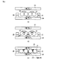
図3は従来の光ファイバテープの一例を示す断面図である。図3に示すように、4本の光ファイバ11を接触させて並行に配置した周囲にテープ樹脂12を被覆するように設けてテープ形状に保持して構成される。
FIG. 3 is a cross-sectional view showing an example of a conventional optical fiber tape. As shown in FIG. 3, four
図9は図3の光ファイバテープの単心分離方法を示す構成説明図である。図9において、13は分離位置である。 FIG. 9 is an explanatory diagram showing the structure of the single-fiber separation method for the optical fiber tape of FIG. In FIG. 9, 13 is a separation position.
図9に示すように、光ファイバテープの単心分離は、光ファイバテープを長手方向に直線状に保持し、保持した光ファイバテープ内の光ファイバ11と光ファイバ11の中間の分離位置13に鋭利な刃を挿入し、鋭利な刃を光ファイバ11の長手方向と平行になるようスライド移動させることにより、必要な長さ分を単心に分離する。
As shown in FIG. 9, the single-fiber separation of the optical fiber tape is performed by holding the optical fiber tape in a straight line in the longitudinal direction and at the
図4は従来考えられている光ファイバテープを示す断面図である。図4において、14は光ファイバ、15はテープ樹脂である。図4に示すように、4本の光ファイバ14を接触させて並行に配置した周囲にテープ樹脂15を極力薄く被覆するように設けてテープ形状に保持して構成される。図4の光ファイバテープを単心分離する場合には、光ファイバテープを長手方向に直線状に保持し、テープ樹脂15を硬いブラシで擦って剥離して光ファイバ14を分離している。
FIG. 4 is a cross-sectional view showing a conventionally considered optical fiber tape. In FIG. 4, 14 is an optical fiber, and 15 is a tape resin. As shown in FIG. 4, a
図3及び図4の光ファイバテープの単心分離は、光ファイバテープを長手方向に保持するため、分離する距離に合わせた長さの保持具が必要になり、保持具が分離距離に合わせた大きな構造となるため、作業スペースの確保も必要であった。 In the single-fiber separation of the optical fiber tape shown in FIGS. 3 and 4, in order to hold the optical fiber tape in the longitudinal direction, a holder having a length corresponding to the distance to be separated is required, and the holder is adjusted to the separation distance. Because of the large structure, it was necessary to secure a work space.
また、分離用の鋭利な刃により繰り返し分離を実施するため、鋭利な刃の劣化や作業不慣れ等による分離の失敗により、分離する光ファイバテープ内の光ファイバに通信障害を発生することが課題となっている。 Further, since separation is repeatedly performed with a sharp blade for separation, it is a problem that a communication failure occurs in the optical fiber in the optical fiber tape to be separated due to failure of separation due to deterioration of the sharp blade or unfamiliar work. It has become.
特許文献1には、光ファイバテープを単心の光ファイバに分離する工具が開示されている。この工具を用いた場合、[1]複数の分割刃への対応、及び[2]分離する長手方向の作業スペースが必要となる。
本発明は上記の事情に鑑みてなされたもので、光ファイバテープのテープ形状の保持と分離の容易さとを両立でき、且つ分離する距離に合わせた長さの保持具を不要として作業スペースを少なくし、鋭利な刃を使用しないことにより通信障害を回避する光ファイバテープ及びその単心分離方法を提供することを目的とする。 The present invention has been made in view of the above circumstances, and can maintain both the tape shape of the optical fiber tape and the ease of separation, and does not require a holder having a length corresponding to the distance to be separated, thereby reducing the work space. In addition, an object of the present invention is to provide an optical fiber tape that avoids communication failure by not using a sharp blade and a single-fiber separation method thereof.
上記目的を達成するために本発明は、複数の光ファイバをテープ樹脂によってテープ形状に保持した光ファイバテープにおいて、テープ樹脂を光ファイバと光ファイバの隣接部近傍に、隣接部が最も高く突出するように配設することを特徴とする光ファイバテープ。 In order to achieve the above object, according to the present invention, in an optical fiber tape in which a plurality of optical fibers are held in a tape shape with a tape resin, the adjacent portion protrudes highest in the vicinity of the adjacent portion between the optical fiber and the optical fiber. An optical fiber tape characterized by being arranged as described above.
また本発明は、前記光ファイバテープにおいて、テープ樹脂が光ファイバと光ファイバの隣接部毎に光ファイバテープの一方の片面もしくは他方の片面に配設されることを特徴とするものである。 According to the present invention, in the optical fiber tape, the tape resin is disposed on one side or the other side of the optical fiber tape for each adjacent portion of the optical fiber.
また本発明は、前記光ファイバテープにおいて、テープ樹脂が光ファイバテープの両面に配設されることを特徴とするものである。 The present invention is also characterized in that in the optical fiber tape, a tape resin is disposed on both surfaces of the optical fiber tape.
また本発明の光ファイバテープの単心分離方法は、前記光ファイバテープに、前記光ファイバテープの光ファイバの直径とほぼ等しい厚さの介在部材を介在して分離工具で上下方向から応力を加えることにより、テープ樹脂を破壊すると共に光ファイバを分離することを特徴とする。 In the optical fiber tape single fiber separation method according to the present invention, stress is applied to the optical fiber tape from above and below with an isolation member having a thickness substantially equal to the diameter of the optical fiber of the optical fiber tape. Thus, the tape resin is broken and the optical fiber is separated.
また本発明の光ファイバテープの単心分離方法は、前記光ファイバテープを、分離工具に設けられたブラシで挟み込み、前記ブラシを光ファイバテープの長手方向にスライドさせることにより、光ファイバがテープ樹脂から剥離して分離することを特徴とする。 The optical fiber tape single-fiber separation method according to the present invention includes sandwiching the optical fiber tape with a brush provided in a separation tool, and sliding the brush in the longitudinal direction of the optical fiber tape so that the optical fiber is a tape resin. It is characterized by peeling from and separating.
本発明の光ファイバテープは、テープ樹脂を光ファイバと光ファイバの隣接部近傍に、隣接部が最も高く突出するように配設することにより、テープ樹脂の厚い部分とテープ樹脂の無い(薄い)部分の2種類を配置することで、テープ形状の保持及び分離の容易さを両立できる。 In the optical fiber tape of the present invention, the tape resin is disposed in the vicinity of the adjacent portion between the optical fiber and the optical fiber so that the adjacent portion protrudes highest, so that there is no thick portion of the tape resin and no tape resin (thin). By arranging the two types of portions, it is possible to achieve both tape shape retention and ease of separation.
また、本発明の光ファイバテープの単心分離方法は、光ファイバと光ファイバの隣接部に位置するテープ樹脂の最も高く突出した部分に応力を加える方法及び軟らかいブラシでテープ樹脂を剥がしとる方法としたことで、分離工具を安価とし、更に作業の簡素化・安全化を図ることができる。 The optical fiber tape single-fiber separation method of the present invention includes a method of applying stress to the highest protruding portion of the tape resin located in the adjacent portion of the optical fiber and the optical fiber, and a method of peeling the tape resin with a soft brush. As a result, the separation tool can be made inexpensive, and the work can be simplified and made safer.
また、本発明の光ファイバテープの単心分離方法は、テープ樹脂を押し潰す方法であるため、長手方向にスライドさせることがなく、長手方向への保持が不要となり、作業スペースも小さくなる。 In addition, since the optical fiber tape single fiber separation method of the present invention is a method of crushing the tape resin, it is not slid in the longitudinal direction, it is not necessary to hold it in the longitudinal direction, and the working space is reduced.
更に、本発明の光ファイバテープの単心分離方法は、テープ樹脂を押し潰す方法であるため、鋭利な刃も不要であり、刃の劣化による光ファイバの通信障害が発生しない。分離作業も、テープ樹脂を押し潰す単純な方法であるため、作業不慣れによる分離の失敗も削減される。 Furthermore, since the optical fiber tape single-fiber separation method of the present invention is a method of crushing the tape resin, a sharp blade is not necessary, and communication failure of the optical fiber due to the deterioration of the blade does not occur. Since the separation work is also a simple method of crushing the tape resin, the failure of separation due to unfamiliar work is reduced.
以下図面を参照して本発明の実施の形態を詳細に説明する。
図1は本発明の第1の実施形態に係る光ファイバテープを示す断面図である。図1において、21は光ファイバ、22はテープ樹脂である。図1に示すように、複数の光ファイバ21はテープ樹脂22によってテープ形状に保持される。前記テープ樹脂22は光ファイバ21と光ファイバ21の隣接部近傍に、隣接部が最も高く突出するように中高に配設される。この場合、テープ樹脂22は光ファイバと光ファイバの隣接部毎に光ファイバテープの一方の片面もしくは他方の片面を選択して片面のみに配設される。
Hereinafter, embodiments of the present invention will be described in detail with reference to the drawings.
FIG. 1 is a cross-sectional view showing an optical fiber tape according to a first embodiment of the present invention. In FIG. 1, 21 is an optical fiber, and 22 is a tape resin. As shown in FIG. 1, the plurality of
図2は本発明の第2の実施形態に係る光ファイバテープを示す断面図である。図2において、31は光ファイバ、32はテープ樹脂である。図2に示すように、複数の光ファイバ31はテープ樹脂32によってテープ形状に保持される。前記テープ樹脂32は光ファイバ31と光ファイバ31の隣接部近傍に、隣接部が最も高く突出するように中高に配設される。前記テープ樹脂32は光ファイバテープの両面にそれぞれ配設される。
FIG. 2 is a cross-sectional view showing an optical fiber tape according to a second embodiment of the present invention. In FIG. 2, 31 is an optical fiber, and 32 is a tape resin. As shown in FIG. 2, the plurality of
尚、テープ樹脂22,32の材質としては、通常の光ファイバテープに用いられているテープ樹脂を用いることができる。例えば、紫外線硬化型のテープ樹脂を用いればよい。このテープ樹脂は、適当な応力をかけることによって、光ファイバから剥離し、破断させることができる。 In addition, as a material of the tape resins 22 and 32, a tape resin used in a normal optical fiber tape can be used. For example, an ultraviolet curable tape resin may be used. The tape resin can be peeled off from the optical fiber and broken by applying an appropriate stress.
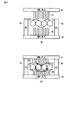
図5(a),(b),(c)は本発明の第1の実施形態に係る光ファイバテープ単心分離方法の一例を示す構成説明図である。図5(a),(b),(c)において、23は上部分離工具、24は下部分離工具、25は介在部材(足)、26は応力が働く方向を示す矢印、27はテープ樹脂の屑である。 FIGS. 5A, 5B, and 5C are configuration explanatory views showing an example of the optical fiber tape single-core separation method according to the first embodiment of the present invention. 5 (a), (b), and (c), 23 is an upper separating tool, 24 is a lower separating tool, 25 is an interposed member (foot), 26 is an arrow indicating the direction in which the stress is applied, and 27 is a tape resin. It is rubbish.
図5(a)に示すように、上面が平坦な下部分離工具24上には図1に示す光ファイバテープが載置されると共に前記光ファイバテープの両側には光ファイバ21の直径とほぼ等しい高さ(厚さ)の介在部材25が設置される。
As shown in FIG. 5A, the optical fiber tape shown in FIG. 1 is placed on the
その後、図5(b)に示すように、下面が平坦な上部分離工具23を前記光ファイバテープの上面より押圧することにより、前記光ファイバテープは介在部材25を介在して上部分離工具23と下部分離工具24で挟み込むようにして上下方向から応力が加えられる。前記光ファイバテープは上下方向から応力が加えられると、矢印26方向に応力が働く。
Thereafter, as shown in FIG. 5 (b), the
その後、図5(c)に示すように、矢印26方向の応力により、光ファイバ21と光ファイバ21の隣接部で、光ファイバ21と光ファイバ21の間隔を押し開くようにして光ファイバが分離されると共にテープ樹脂22は押し潰され破壊されて屑27となる。
After that, as shown in FIG. 5C, the optical fiber is separated by pushing the gap between the
尚、上部分離工具23と下部分離工具24の間に光ファイバ21の直径とほぼ等しい高さの介在部材25が設置されることにより、上部分離工具23と下部分離工具24で光ファイバテープを挟み込むようにして上下方向から応力が加えられても、光ファイバ21に損傷を与えることはない。
Note that an optical fiber tape is sandwiched between the
図6(a),(b),(c)は本発明の第1の実施形態に係る光ファイバテープ単心分離方法の他の例を示す構成説明図である。図6(a),(b),(c)において、33は上部分離工具、34は下部分離工具、35は介在部材(足)、36は応力が働く方向を示す矢印、37はテープ樹脂の屑である。 FIGS. 6A, 6B, and 6C are configuration explanatory views showing another example of the optical fiber tape single-core separation method according to the first embodiment of the present invention. 6 (a), 6 (b) and 6 (c), 33 is an upper separating tool, 34 is a lower separating tool, 35 is an interposition member (foot), 36 is an arrow indicating the direction in which stress is applied, and 37 is a tape resin. It is rubbish.
図6(a)に示すように、上面が平坦な下部分離工具34上には図2に示す光ファイバテープが載置されると共に前記光ファイバテープの両側には光ファイバ31の直径とほぼ等しい高さ(厚さ)の介在部材35が設置される。
As shown in FIG. 6A, the optical fiber tape shown in FIG. 2 is placed on the
その後、図6(b)に示すように、下面が平坦な上部分離工具33を前記光ファイバテープの上面より押圧することにより、前記光ファイバテープは介在部材35を介在して上部分離工具33と下部分離工具34で挟み込むようにして上下方向から応力が加えられる。前記光ファイバテープは上下方向から応力が加えられると、矢印36方向に応力が働く。
Thereafter, as shown in FIG. 6B, the
その後、図6(c)に示すように、矢印36方向の応力により、光ファイバ31と光ファイバ31の隣接部で、光ファイバ31と光ファイバ31の間隔を押し開くようにして光ファイバが分離されると共にテープ樹脂32は押し潰され破壊されて屑37となる。
After that, as shown in FIG. 6C, the optical fiber is separated by pushing the gap between the
尚、上部分離工具33と下部分離工具34の間に光ファイバ31の直径とほぼ等しい厚さの介在部材35が設置されることにより、上部分離工具33と下部分離工具34で光ファイバテープを挟み込むようにして上下方向から応力が加えられても、光ファイバ31に損傷を与えることはない。
Note that an optical fiber tape is sandwiched between the
図8は本発明の実施形態に係る分離工具を示す一部切欠斜視図である。図8に示すように、上部分離工具23(33)は断面コ字状に形成されると共に底面が平坦に形成される。下部分離工具24(34)は両側近傍に介在部材(足)25(35)が底面より光ファイバ31の直径とほぼ等しい高さ突出して設けられると共に底面は平坦に形成される。前記下部分離工具24(34)の介在部材25(35)の外側段部には上部分離工具23(33)の開口端が載置される。前記上部分離工具23(33)の一方の開口端縁と、前記下部分離工具24(34)の一方の開口端縁とは例えば蝶番等の回動部材28で回動自在に取り付けられる。
FIG. 8 is a partially cutaway perspective view showing the separation tool according to the embodiment of the present invention. As shown in FIG. 8, the upper separation tool 23 (33) has a U-shaped cross section and a flat bottom surface. In the lower separation tool 24 (34), intervening members (foot) 25 (35) are provided in the vicinity of both sides so as to protrude from the bottom surface to a height substantially equal to the diameter of the
図7(a),(b)は本発明の第2の実施形態に係る光ファイバテープ単心分離方法を示す構成説明図である。図7(a),(b)において、41は上部分離工具、42は下部分離工具、43は介在部材(足)、44,45は軟らかいブラシである。 FIGS. 7 (a) and 7 (b) are structural explanatory views showing an optical fiber tape single-core separation method according to the second embodiment of the present invention. 7 (a) and 7 (b), 41 is an upper separating tool, 42 is a lower separating tool, 43 is an interposed member (foot), and 44 and 45 are soft brushes.
図7(a)に示すように、下部分離工具42の上面には複数の軟らかいブラシ45が植毛されると共に両側に介在部材(足)43が上方に突出して設けられる。前記ブラシ45上には図1の光ファイバテープが載置され、前記光ファイバテープの上方には下面に複数の軟らかいブラシ44が植毛された上部分離工具41が降下可能にして設けられる。
As shown in FIG. 7A, a plurality of
その後、図7(b)に示すように、上部分離工具41が降下して介在部材(足)43上に押し当てられると共にブラシ44,45が前記光ファイバテープの上面及び下面に上下方向から挟み込むようにして押し当てられる。ブラシ44,45が前記光ファイバテープの上面及び下面に挟み込むようにして押し当てられることにより、ブラシ44,45の先端部分が前記光ファイバテープの光ファイバ21と光ファイバ21の隙間等に入り込む(黒破線部分)。この状態で上部分離工具41、下部分離工具42、及び介在部材(足)43よりなる分離工具を光ファイバテープの長手方向に繰り返しスライドさせることにより、光ファイバ21がテープ樹脂22から剥離して分離する。尚、ブラシ44,45として軟らかいブラシ(例えば柔らかい歯ブラシ等)を用いることにより、分離作業実施時に無理な応力が光ファイバテープに加えられても、通信障害を回避可能である。
Thereafter, as shown in FIG. 7B, the
なお、本発明は、上記実施形態そのままに限定されるものではなく、実施段階ではその要旨を逸脱しない範囲で構成要素を変形して具体化できる。また、上記実施形態に開示されている複数の構成要素の適宜な組み合せにより種々の発明を形成できる。例えば、実施形態に示される全構成要素から幾つかの構成要素を削除してもよい。更に、異なる実施形態に亘る構成要素を適宜組み合せてもよい。 Note that the present invention is not limited to the above-described embodiment as it is, and can be embodied by modifying the constituent elements without departing from the scope of the invention in the implementation stage. Further, various inventions can be formed by appropriately combining a plurality of constituent elements disclosed in the embodiment. For example, some components may be deleted from all the components shown in the embodiment. Furthermore, you may combine suitably the component covering different embodiment.
21…光ファイバ、22…テープ樹脂、23…上部分離工具、24…下部分離工具、25…介在部材(足)、26…応力が働く方向を示す矢印、27…テープ樹脂の屑、31…光ファイバ、32…テープ樹脂、33…上部分離工具、34…下部分離工具、35…介在部材(足)、36…応力が働く方向を示す矢印、37…テープ樹脂の屑。
DESCRIPTION OF
Claims (5)
テープ樹脂を光ファイバと光ファイバの隣接部近傍に、隣接部が最も高く突出するように配設することを特徴とする光ファイバテープ。 In an optical fiber tape in which a plurality of optical fibers are held in a tape shape by tape resin,
An optical fiber tape, wherein a tape resin is disposed in the vicinity of an adjacent portion between the optical fiber and the optical fiber so that the adjacent portion protrudes highest.
Priority Applications (1)
| Application Number | Priority Date | Filing Date | Title |
|---|---|---|---|
| JP2008210050A JP5000605B2 (en) | 2008-08-18 | 2008-08-18 | Single fiber separation method of optical fiber tape |
Applications Claiming Priority (1)
| Application Number | Priority Date | Filing Date | Title |
|---|---|---|---|
| JP2008210050A JP5000605B2 (en) | 2008-08-18 | 2008-08-18 | Single fiber separation method of optical fiber tape |
Publications (2)
| Publication Number | Publication Date |
|---|---|
| JP2010044336A true JP2010044336A (en) | 2010-02-25 |
| JP5000605B2 JP5000605B2 (en) | 2012-08-15 |
Family
ID=42015751
Family Applications (1)
| Application Number | Title | Priority Date | Filing Date |
|---|---|---|---|
| JP2008210050A Expired - Fee Related JP5000605B2 (en) | 2008-08-18 | 2008-08-18 | Single fiber separation method of optical fiber tape |
Country Status (1)
| Country | Link |
|---|---|
| JP (1) | JP5000605B2 (en) |
Cited By (19)
| Publication number | Priority date | Publication date | Assignee | Title |
|---|---|---|---|---|
| JP2011185992A (en) * | 2010-03-04 | 2011-09-22 | Fujikura Ltd | Method and apparatus for manufacturing of optical fiber ribbon |
| JP2011186166A (en) * | 2010-03-08 | 2011-09-22 | Fujikura Ltd | Split tool for optical fiber ribbon |
| JP2012027200A (en) * | 2010-07-22 | 2012-02-09 | Nippon Telegr & Teleph Corp <Ntt> | Single core separation tool for optical fiber ribbon and single core separation device |
| JP2013182156A (en) * | 2012-03-02 | 2013-09-12 | Fujikura Ltd | Optical fiber ribbon and optical fiber cable |
| CN104849819A (en) * | 2015-05-28 | 2015-08-19 | 上海鸿辉光通科技股份有限公司 | Fiber splitting method of four-core tape fiber and eight-core tape fiber |
| JP2016146003A (en) * | 2016-05-20 | 2016-08-12 | 日本電信電話株式会社 | Intermittently adhered optical fiber ribbon and optical cable using the same |
| US10185105B2 (en) | 2016-07-27 | 2019-01-22 | Prysmian S.P.A. | Flexible optical-fiber ribbon |
| US10718917B2 (en) | 2018-08-24 | 2020-07-21 | Prysmian S.P.A. | Flexible optical fiber ribbons and methods of formation thereof |
| US10782495B2 (en) | 2018-01-15 | 2020-09-22 | Prysmian S.P.A. | Flexible optical-fiber ribbon |
| US10884213B1 (en) | 2019-11-14 | 2021-01-05 | Prysmian S.P.A. | Optical-fiber ribbon with distorted sinusoidal adhesive pattern and method therefor |
| US10983297B2 (en) | 2017-07-11 | 2021-04-20 | Prysmian S.P.A. | Optical fiber ribbon and a method of producing the same |
| US11131816B2 (en) | 2017-07-11 | 2021-09-28 | Prysmian S.P.A. | Optical fiber ribbon assembly and a method of producing the same |
| EP3876011A3 (en) * | 2020-03-04 | 2021-11-24 | Sterlite Technologies Limited | Optical fibre ribbon having bond shape |
| US11256051B2 (en) | 2018-01-15 | 2022-02-22 | Prysmian S.P.A. | Flexible optical-fiber ribbon |
| US11262516B2 (en) | 2018-07-05 | 2022-03-01 | Prysmian S.P.A. | High density optical cables |
| US11442238B2 (en) | 2020-12-22 | 2022-09-13 | Prysmian S.P.A. | Optical-fiber ribbon with spaced optical-fiber units |
| US11460652B2 (en) | 2020-12-22 | 2022-10-04 | Prysmian S.P.A. | Optical-fiber ribbon with adhesive-free gaps |
| US11500171B2 (en) | 2018-01-15 | 2022-11-15 | Prysmian S.P.A. | Optical fiber ribbon and a method and system of producing the same |
| US11860429B2 (en) | 2020-12-22 | 2024-01-02 | Prysmian S.P.A. | Optical-fiber ribbon with spaced optical-fiber units |
Citations (6)
| Publication number | Priority date | Publication date | Assignee | Title |
|---|---|---|---|---|
| JPH10319251A (en) * | 1997-05-15 | 1998-12-04 | Mitsubishi Cable Ind Ltd | Single core separating tool of optical fiber tape |
| JP2000231043A (en) * | 1999-02-09 | 2000-08-22 | Fujikura Ltd | Coated optical tape, its production and dice for production of coated optical tape used for that method |
| JP2003232972A (en) * | 2002-02-07 | 2003-08-22 | Sumitomo Electric Ind Ltd | Coated optical fiber tape |
| JP2004240014A (en) * | 2003-02-04 | 2004-08-26 | Sumitomo Electric Ind Ltd | Method of branching coated optical fiber tape, tool for branching the coated optical fiber tape and coated optical fiber tape |
| JP2005227802A (en) * | 2005-05-09 | 2005-08-25 | Sumitomo Electric Ind Ltd | Method and tool for branching coated optical fiber ribbon |
| JP2008176120A (en) * | 2007-01-19 | 2008-07-31 | Swcc Showa Cable Systems Co Ltd | Optical fiber ribbon and optical cable |
-
2008
- 2008-08-18 JP JP2008210050A patent/JP5000605B2/en not_active Expired - Fee Related
Patent Citations (6)
| Publication number | Priority date | Publication date | Assignee | Title |
|---|---|---|---|---|
| JPH10319251A (en) * | 1997-05-15 | 1998-12-04 | Mitsubishi Cable Ind Ltd | Single core separating tool of optical fiber tape |
| JP2000231043A (en) * | 1999-02-09 | 2000-08-22 | Fujikura Ltd | Coated optical tape, its production and dice for production of coated optical tape used for that method |
| JP2003232972A (en) * | 2002-02-07 | 2003-08-22 | Sumitomo Electric Ind Ltd | Coated optical fiber tape |
| JP2004240014A (en) * | 2003-02-04 | 2004-08-26 | Sumitomo Electric Ind Ltd | Method of branching coated optical fiber tape, tool for branching the coated optical fiber tape and coated optical fiber tape |
| JP2005227802A (en) * | 2005-05-09 | 2005-08-25 | Sumitomo Electric Ind Ltd | Method and tool for branching coated optical fiber ribbon |
| JP2008176120A (en) * | 2007-01-19 | 2008-07-31 | Swcc Showa Cable Systems Co Ltd | Optical fiber ribbon and optical cable |
Cited By (23)
| Publication number | Priority date | Publication date | Assignee | Title |
|---|---|---|---|---|
| JP2011185992A (en) * | 2010-03-04 | 2011-09-22 | Fujikura Ltd | Method and apparatus for manufacturing of optical fiber ribbon |
| JP2011186166A (en) * | 2010-03-08 | 2011-09-22 | Fujikura Ltd | Split tool for optical fiber ribbon |
| JP2012027200A (en) * | 2010-07-22 | 2012-02-09 | Nippon Telegr & Teleph Corp <Ntt> | Single core separation tool for optical fiber ribbon and single core separation device |
| JP2013182156A (en) * | 2012-03-02 | 2013-09-12 | Fujikura Ltd | Optical fiber ribbon and optical fiber cable |
| CN104849819A (en) * | 2015-05-28 | 2015-08-19 | 上海鸿辉光通科技股份有限公司 | Fiber splitting method of four-core tape fiber and eight-core tape fiber |
| CN104849819B (en) * | 2015-05-28 | 2017-10-03 | 上海鸿辉光通科技股份有限公司 | Point method for fiber that four core ribbon are fine and eight core ribbon are fine |
| JP2016146003A (en) * | 2016-05-20 | 2016-08-12 | 日本電信電話株式会社 | Intermittently adhered optical fiber ribbon and optical cable using the same |
| US10185105B2 (en) | 2016-07-27 | 2019-01-22 | Prysmian S.P.A. | Flexible optical-fiber ribbon |
| US10983297B2 (en) | 2017-07-11 | 2021-04-20 | Prysmian S.P.A. | Optical fiber ribbon and a method of producing the same |
| US11131816B2 (en) | 2017-07-11 | 2021-09-28 | Prysmian S.P.A. | Optical fiber ribbon assembly and a method of producing the same |
| US11256051B2 (en) | 2018-01-15 | 2022-02-22 | Prysmian S.P.A. | Flexible optical-fiber ribbon |
| US10782495B2 (en) | 2018-01-15 | 2020-09-22 | Prysmian S.P.A. | Flexible optical-fiber ribbon |
| US11169342B2 (en) | 2018-01-15 | 2021-11-09 | Prysmian S.P.A. | Flexible optical-fiber ribbon |
| US11500171B2 (en) | 2018-01-15 | 2022-11-15 | Prysmian S.P.A. | Optical fiber ribbon and a method and system of producing the same |
| US11656417B2 (en) | 2018-01-15 | 2023-05-23 | Prysmian S.P.A. | Flexible optical-fiber ribbon |
| US11262516B2 (en) | 2018-07-05 | 2022-03-01 | Prysmian S.P.A. | High density optical cables |
| US11796750B2 (en) | 2018-07-05 | 2023-10-24 | Prysmian S.P.A. | High density optical cables |
| US10718917B2 (en) | 2018-08-24 | 2020-07-21 | Prysmian S.P.A. | Flexible optical fiber ribbons and methods of formation thereof |
| US10884213B1 (en) | 2019-11-14 | 2021-01-05 | Prysmian S.P.A. | Optical-fiber ribbon with distorted sinusoidal adhesive pattern and method therefor |
| EP3876011A3 (en) * | 2020-03-04 | 2021-11-24 | Sterlite Technologies Limited | Optical fibre ribbon having bond shape |
| US11442238B2 (en) | 2020-12-22 | 2022-09-13 | Prysmian S.P.A. | Optical-fiber ribbon with spaced optical-fiber units |
| US11460652B2 (en) | 2020-12-22 | 2022-10-04 | Prysmian S.P.A. | Optical-fiber ribbon with adhesive-free gaps |
| US11860429B2 (en) | 2020-12-22 | 2024-01-02 | Prysmian S.P.A. | Optical-fiber ribbon with spaced optical-fiber units |
Also Published As
| Publication number | Publication date |
|---|---|
| JP5000605B2 (en) | 2012-08-15 |
Similar Documents
| Publication | Publication Date | Title |
|---|---|---|
| JP5000605B2 (en) | Single fiber separation method of optical fiber tape | |
| WO2004001474A3 (en) | Ferrule assembly and associated fabrication method | |
| EP1168024B1 (en) | Optical fiber cable with ripcords | |
| KR20090100728A (en) | Connector for electric wire jonit | |
| JP2008292710A (en) | Optical connector and assembling method thereof | |
| JP5191949B2 (en) | Optical connector with assembly member, method for assembling the same, and optical connector | |
| JP2010029040A (en) | Indirect hot-line work tool and indirect hot-line connection method | |
| JP5721686B2 (en) | Optical fiber ribbon and optical fiber cable | |
| JP2010091730A (en) | Optical fiber ribbon and single-fiber separating method of the same | |
| JP5480229B2 (en) | Optical connector assembly and method of connecting optical fiber to optical connector assembly | |
| JP5607590B2 (en) | Reinforcing sleeve and optical fiber core wire fusion splicing method | |
| JP2008003475A (en) | Mechanical splice | |
| JP5224414B2 (en) | Optical fiber holding member, coating removal method and fusion method for multi-layer coated optical fiber | |
| JP5666761B2 (en) | Separation method and separation tool for optical fiber ribbon | |
| JP2009210930A (en) | Optical fiber tape and its single-core separation tool | |
| JP7407549B2 (en) | Optical fiber sheath removal device and optical fiber sheath removal method | |
| JP6025693B2 (en) | Attachment capable of being attached to and detached from an optical fiber tape dividing tool and optical fiber tape dividing method | |
| JP4115440B2 (en) | Optical cable holder | |
| JP2006030684A (en) | Method and tool for separating optical fiber ribbon | |
| JP5804805B2 (en) | Optical fiber connection member, optical fiber connection method, optical fiber connection structure | |
| JP2007121772A (en) | Coated optical fiber holder | |
| US20220187539A1 (en) | Ribbon splicing tools and methods | |
| JP2006047390A (en) | Optical fiber cable and method for taking out coated optical fiber ribbon | |
| JP5199294B2 (en) | Optical fiber holder | |
| JP4919818B2 (en) | Optical cable connector |
Legal Events
| Date | Code | Title | Description |
|---|---|---|---|
| A621 | Written request for application examination |
Free format text: JAPANESE INTERMEDIATE CODE: A621 Effective date: 20100805 |
|
| A977 | Report on retrieval |
Free format text: JAPANESE INTERMEDIATE CODE: A971007 Effective date: 20110912 |
|
| A131 | Notification of reasons for refusal |
Free format text: JAPANESE INTERMEDIATE CODE: A131 Effective date: 20110927 |
|
| A521 | Request for written amendment filed |
Free format text: JAPANESE INTERMEDIATE CODE: A523 Effective date: 20111124 |
|
| TRDD | Decision of grant or rejection written | ||
| A01 | Written decision to grant a patent or to grant a registration (utility model) |
Free format text: JAPANESE INTERMEDIATE CODE: A01 Effective date: 20120508 |
|
| A01 | Written decision to grant a patent or to grant a registration (utility model) |
Free format text: JAPANESE INTERMEDIATE CODE: A01 |
|
| A61 | First payment of annual fees (during grant procedure) |
Free format text: JAPANESE INTERMEDIATE CODE: A61 Effective date: 20120516 |
|
| R150 | Certificate of patent or registration of utility model |
Free format text: JAPANESE INTERMEDIATE CODE: R150 |
|
| FPAY | Renewal fee payment (event date is renewal date of database) |
Free format text: PAYMENT UNTIL: 20150525 Year of fee payment: 3 |
|
| S531 | Written request for registration of change of domicile |
Free format text: JAPANESE INTERMEDIATE CODE: R313531 |
|
| R350 | Written notification of registration of transfer |
Free format text: JAPANESE INTERMEDIATE CODE: R350 |
|
| LAPS | Cancellation because of no payment of annual fees |