JP2010044102A - Inner focus zoom lens barrel - Google Patents
Inner focus zoom lens barrel Download PDFInfo
- Publication number
- JP2010044102A JP2010044102A JP2008206017A JP2008206017A JP2010044102A JP 2010044102 A JP2010044102 A JP 2010044102A JP 2008206017 A JP2008206017 A JP 2008206017A JP 2008206017 A JP2008206017 A JP 2008206017A JP 2010044102 A JP2010044102 A JP 2010044102A
- Authority
- JP
- Japan
- Prior art keywords
- lens group
- cylinder
- cam
- zoom
- focus
- Prior art date
- Legal status (The legal status is an assumption and is not a legal conclusion. Google has not performed a legal analysis and makes no representation as to the accuracy of the status listed.)
- Granted
Links
Images


Classifications
-
- G—PHYSICS
- G02—OPTICS
- G02B—OPTICAL ELEMENTS, SYSTEMS OR APPARATUS
- G02B7/00—Mountings, adjusting means, or light-tight connections, for optical elements
- G02B7/02—Mountings, adjusting means, or light-tight connections, for optical elements for lenses
- G02B7/04—Mountings, adjusting means, or light-tight connections, for optical elements for lenses with mechanism for focusing or varying magnification
- G02B7/10—Mountings, adjusting means, or light-tight connections, for optical elements for lenses with mechanism for focusing or varying magnification by relative axial movement of several lenses, e.g. of varifocal objective lens
- G02B7/102—Mountings, adjusting means, or light-tight connections, for optical elements for lenses with mechanism for focusing or varying magnification by relative axial movement of several lenses, e.g. of varifocal objective lens controlled by a microcomputer
-
- G—PHYSICS
- G02—OPTICS
- G02B—OPTICAL ELEMENTS, SYSTEMS OR APPARATUS
- G02B15/00—Optical objectives with means for varying the magnification
- G02B15/14—Optical objectives with means for varying the magnification by axial movement of one or more lenses or groups of lenses relative to the image plane for continuously varying the equivalent focal length of the objective
- G02B15/144—Optical objectives with means for varying the magnification by axial movement of one or more lenses or groups of lenses relative to the image plane for continuously varying the equivalent focal length of the objective having four groups only
- G02B15/1441—Optical objectives with means for varying the magnification by axial movement of one or more lenses or groups of lenses relative to the image plane for continuously varying the equivalent focal length of the objective having four groups only the first group being positive
- G02B15/144113—Optical objectives with means for varying the magnification by axial movement of one or more lenses or groups of lenses relative to the image plane for continuously varying the equivalent focal length of the objective having four groups only the first group being positive arranged +-++
Landscapes
- Physics & Mathematics (AREA)
- General Physics & Mathematics (AREA)
- Optics & Photonics (AREA)
- Engineering & Computer Science (AREA)
- General Engineering & Computer Science (AREA)
- Lens Barrels (AREA)
- Adjustment Of Camera Lenses (AREA)
Abstract
Description
本発明は、インナーフォーカスズームレンズ鏡筒、さらに詳しくは、15倍前後のズーム比が実現可能なインナフォーカスズームレンズに適したインナーフォーカスズームレンズ鏡筒に関する。 The present invention relates to an inner focus zoom lens barrel, and more particularly to an inner focus zoom lens barrel suitable for an inner focus zoom lens capable of realizing a zoom ratio of around 15 times.
インナフォーカス方式の高倍率ズームレンズにおいては、至近距離側に対する合焦レンズの繰出し量の変化率が大きく、一本のフォーカスカム内で至近距離性能を拡大しようとすると、他のズーム領域における焦点移動が大きくなって、いわゆるバリフォーカルが発生する。このバリフォーカルをズーム域に変換するファーカスカムカーブでは、ズームのパラメーターとフォーカスのパラメーターを適切に配置する必要がある。しかし、ズーミング操作、及びフォーカス操作を滑らかに行うためにバランスのとれたカム形状を確保することが困難となり、フォーカスカム回転角の変換、あるいはフォーカスカムでの補正が必要となる。 In an inner focus type high-power zoom lens, the rate of change of the focusing lens feed amount with respect to the close-up distance is large, and when trying to expand the close-up distance performance within one focus cam, the focus shifts in other zoom areas. Increases so-called varifocal. In the focus cam curve for converting this varifocal into the zoom range, it is necessary to appropriately arrange the zoom parameter and the focus parameter. However, it is difficult to ensure a well-balanced cam shape in order to smoothly perform the zooming operation and the focus operation, and conversion of the focus cam rotation angle or correction with the focus cam is required.
従来の高倍率ズームレンズにおいては、ズーミング操作及びフォーカシング操作の何れの時でもフォーカスレンズを回転させながら移動させる。そして、フォーカスカム筒の回転操作用の案内溝をカム形状とすることにより、案内溝に係合する操作ピンがズーミングによってフォーカスカム筒の回転操作用案内溝を移動するため、ズーミング操作によってフォーカスカム上の操作範囲を回転方向によって変位させて各ズーム領域における適切なフォーカシング繰出し量を得ている(例えば、特許文献1参照)。
しかし、より至近距離性能の拡大や、全ズーム領域における焦点移動を抑えた上でフォーカシング繰出し量を得るために十分な変位量を確保することはなお困難である。また、この5倍程度の高倍率ズームレンズにおいては、固定筒の内側に第1カム筒が配置され、固定筒の外側に第2カム筒、直進筒、第3カム筒が配置され、いわゆる5層構造であり、外径を小さくできない問題があった。また、手振れ防止機構の組込みについては、何ら考慮されていない。
In a conventional high-magnification zoom lens, the focus lens is rotated and moved during both the zooming operation and the focusing operation. Since the guide groove for rotational operation of the focus cam cylinder is formed into a cam shape, the operation pin engaged with the guide groove moves through the guide groove for rotation operation of the focus cam cylinder by zooming. The upper operation range is displaced according to the rotation direction to obtain an appropriate focusing feed amount in each zoom area (see, for example, Patent Document 1).
However, it is still difficult to secure a sufficient amount of displacement to obtain a focusing feed amount while further increasing the close-range performance and suppressing the focus movement in the entire zoom region. In this high-power zoom lens of about 5 times, the first cam cylinder is arranged inside the fixed cylinder, and the second cam cylinder, the straight advance cylinder, and the third cam cylinder are arranged outside the fixed cylinder. There was a problem that the outer diameter could not be reduced due to the layer structure. In addition, no consideration is given to the incorporation of a camera shake prevention mechanism.
他の従来の高倍率ズームレンズにおいては、フォーカス補正カムをフォーカスカムと同一回転部材に配置することにより、フォーカス繰出し量を得ている(例えば、特許文献2参照)。しかし、ズーミング操作時にフォーカスレンズを直進させる機構としているため、何れのズーム領域においても一定量の補正量が与えられ、高倍率ズームレンズにおいて何れのズーム領域においても至近距離を短縮させるのに十分な補正量を与えることはできない。また、この高倍率ズームレンズにおいては、固定筒の外側に、第1カム筒、第2カム筒、直進筒、第3カム筒を配置したいわゆる5層構造であり、外径を小さくできない問題があった。また、手振れ防止機構の組込みについては、何ら考慮されていない。 In other conventional high-magnification zoom lenses, the focus feed-out amount is obtained by arranging the focus correction cam on the same rotating member as the focus cam (see, for example, Patent Document 2). However, since the focus lens is moved straight during zooming operation, a fixed amount of correction is given in any zoom area, which is sufficient for shortening the closest distance in any zoom area in a high magnification zoom lens. A correction amount cannot be given. Further, this high-power zoom lens has a so-called five-layer structure in which the first cam cylinder, the second cam cylinder, the rectilinear cylinder, and the third cam cylinder are arranged outside the fixed cylinder, and there is a problem that the outer diameter cannot be reduced. there were. In addition, no consideration is given to the incorporation of a camera shake prevention mechanism.
さらに他の従来の高倍率ズームレンズにおいては、図10及び図11に示すように、固定筒12の内側に配置されたズーム連動リング14と、ズーム連動リング14の内側に配置された第1カム筒16と、第1カム筒16の内側に配置された直進筒18の内側に配置されたフォーカスカム筒20を有する。また、第1カム筒16は、ズーム連動コマ40を介してズーム連動リング14に連結されていて、ズームリング30の回動が第1カム筒16に伝達される。第1カム筒16は、第1カム筒を光軸方向移動させるために第1カム筒ガイドコマ39が係合する第1カム筒ガイドカムと、第3群レンズガイドコマ43が係合する第3群レンズガイドカムと、第4群レンズガイドコマ45が係合する第4群レンズガイドカムと有する。第1カム筒16はまた、固定筒12の前方すなわちレンズマウント部10と反対側において、第2カム筒連動コマ50が外向きに設けられている。第2カム筒連動コマ50は、第2カム筒22に設けられた縦ガイド溝に係合している(例えば、特許文献3参照)。
In another conventional high-power zoom lens, as shown in FIGS. 10 and 11, the
上述した高倍率ズームレンズにおいては、固定筒12の内径にズーム連動リング14、ズーム連動リング14の内径側に配置された第1カム筒16と、第1カム筒16の内径側に配置された直進筒18を有する。第1カム筒は、ズーム連動コマ40を介してズーム連動リング14に連結されていて、ズームリング30の回動が第1カム筒16に伝達される。第1カム筒16を光軸方向へ移動させるため、第1カム筒16には、第1カム筒ガイドコマ39が係合する第1カム筒ガイドカムと、第3レンズ群ガイドコマ43が係合する第3レンズ群ガイドカムと、第4レンズ群ガイドコマ45が係合する第4レンズ群ガイドカムとを形成しなければならない。
In the high-power zoom lens described above, the zoom interlocking
しかし、第1カム筒16には光軸方向の全長が制約されているため、第1カム筒ガイドカム、第3レンズ群ガイドカム及び第4レンズ群ガイドカムのレイアウトには光軸方向長さの制約がある。特に、ズーム比のより高倍化を図るためには、第3群レンズ、及び第4群レンズの光軸方向への移動量を増加させなければならないが、第1カム筒16の可能な光軸方向寸法の中でこれらのガイドカムをバランスよく配置することは困難である。すなわち、これらのガイドカムを無理して配置すれば、これらのガイドカムの形状及び位置の制限が増し、自由度が無くなってしまう問題があった。
さらに、固定筒12の構成可能な全長に対し、直進筒18の移動量が第3レンズ群の移動量の増加と共に増加するため、望遠側繰出し時に固定筒12と直進筒18との嵌め合い量すなわち掛かり量が小さくなって鏡筒の必要な安定性が保てなくなってしまう問題があった。また、手振れ防止機構の組込みについては、何ら考慮されていない。
However, since the total length in the optical axis direction of the
Further, the amount of movement of the
一方、径方向の小型化を実現できるレンズ鏡筒を構成するために、振れ補正ユニットと、前記振れ補正ユニットと共に撮影光学系の少なくとも一部を構成するレンズを支持するレンズ枠とを有するレンズ鏡筒において、前記レンズ枠の回転を制限する制限部材を前記振れ補正ユニットに配置したレンズ鏡筒が提案されている(例えば、特許文献4参照)。 On the other hand, in order to configure a lens barrel that can achieve a reduction in size in the radial direction, a lens mirror having a shake correction unit and a lens frame that supports a lens that forms at least a part of the photographing optical system together with the shake correction unit. There has been proposed a lens barrel in which a restricting member that restricts rotation of the lens frame is arranged in the shake correction unit (for example, see Patent Document 4).
(発明の目的)
本発明は、従来のズームレンズ鏡筒、特にインナーフォーカスズームレンズの鏡筒の上述した問題点に鑑みてなされたものであって、15倍前後のズーム比も実現可能であり、かつズーミング操作及びフォーカス操作を滑らかに行うためにバランスのとれたカム形状を持ち、さらに手振れ防止機構も容易に組み込むことができるインナーフォーカスズームレンズ鏡筒を提供することを目的とする。
(Object of invention)
The present invention has been made in view of the above-described problems of conventional zoom lens barrels, particularly inner focus zoom lens barrels, and can achieve a zoom ratio of around 15 times. It is an object of the present invention to provide an inner focus zoom lens barrel that has a well-balanced cam shape for smoothly performing a focus operation and can easily incorporate a shake prevention mechanism.
本発明はまた、十分な至近距離性能及び全ズーム領域における焦点移動を抑え、かつ外径が小さいインナーフォーカスズームレンズ鏡筒を提供することを目的とする。 It is another object of the present invention to provide an inner focus zoom lens barrel that has a sufficiently close range performance and a focus movement in the entire zoom region and that has a small outer diameter.
本発明はさらに、ガイドカムの形状及び位置の制限が少なく、また望遠側繰出し時に固定筒と直進筒との嵌め合い量すなわち掛かり量が大きく、安定性の高いインナーフォーカスズームレンズ鏡筒を提供することを目的とする。 The present invention further provides a highly stable inner focus zoom lens barrel that has less restrictions on the shape and position of the guide cam and has a large amount of engagement between the fixed barrel and the rectilinear barrel when extended to the telephoto side. For the purpose.
第1発明は、固定筒と、該固定筒の内側に順次配置されたフォーカスカム筒、直進筒、及び第1カム筒を配置し、該固定筒の外側に順次配置されたズーム連動リング、第2カム筒、及び第1レンズ群摺動筒を配置したことを特徴とするインナフォーカスズームレンズ鏡筒である。 According to a first aspect of the present invention, there is provided a fixed cylinder, a focus cam cylinder, a rectilinear cylinder, and a first cam cylinder that are sequentially arranged inside the fixed cylinder, and a zoom interlocking ring that is sequentially arranged outside the fixed cylinder, An inner focus zoom lens barrel having a two-cam barrel and a first lens group sliding barrel.
第2発明は、固定筒と、該固定筒の内側に順次配置されたフォーカスカム筒、直進筒、及び第1カム筒を配置し、該固定筒の外側に順次配置されたズーム連動リング、第2カム筒、及び第1レンズ群摺動筒を配置し、物体側より順に、正の屈折力を持つ第1レンズ群、フォーカシングレンズであり負の屈折力をもつ第2レンズ群、正の屈折力を持つ第3レンズ群、正の屈折力をもつ第4レンズ群で構成し、広角端から望遠端への変倍により第1レンズ群と第2レンズ群の間隔が広がり、第2レンズ群と第3レンズ群の間隔が狭まり、第3レンズ群と第4レンズ群間隔が狭まるように移動し、前記第3レンズ群の後群を光軸と直交する方向へ移動させることで手振れ発生時の像面補正を行うことを特徴とするインナフォーカスズームレンズ鏡筒である。 A second invention includes a fixed cylinder, a focus cam cylinder, a rectilinear cylinder, and a first cam cylinder that are sequentially arranged inside the fixed cylinder, and a zoom interlocking ring that is sequentially arranged outside the fixed cylinder, A two-cam cylinder and a first lens group sliding cylinder are arranged, and in order from the object side, a first lens group having a positive refractive power, a focusing lens and a second lens group having a negative refractive power, a positive refraction A third lens group having a positive power and a fourth lens group having a positive refractive power, and the distance between the first lens group and the second lens group is widened by zooming from the wide-angle end to the telephoto end. And the third lens group is narrowed, the third lens group and the fourth lens group are moved so as to be narrowed, and the rear group of the third lens group is moved in a direction perpendicular to the optical axis, thereby causing camera shake. Inner focus zoom lens barrel characterized by performing image plane correction A.
本発明のインナーフォーカスズームレンズ鏡筒は、15倍前後のズーム比も実現可能であり、かつズーミング操作及びフォーカス操作を滑らかに行うためにバランスのとれたカム形状を持ち、さらに手振れ防止機構も容易に組み込むことができるインナーフォーカスズームレンズ鏡筒を構成することができる効果を有する。 The inner focus zoom lens barrel of the present invention can achieve a zoom ratio of about 15 times, has a well-balanced cam shape for smooth zooming operation and focus operation, and is easy to prevent camera shake. An inner focus zoom lens barrel that can be incorporated into the lens can be configured.
本発明のインナーフォーカスズームレンズ鏡筒は、また、十分な至近距離性能及び全ズーム領域における焦点移動を抑え、かつ外径が小さいインナーフォーカスズームレンズ鏡筒を構成することができる効果を有する。 The inner focus zoom lens barrel of the present invention also has an effect that it is possible to configure an inner focus zoom lens barrel having a sufficiently close distance performance, a reduction in focal point movement in the entire zoom region, and a small outer diameter.
本発明のインナーフォーカスズームレンズ鏡筒はさらに、ガイドカムの形状及び位置の制限が少なく、また望遠側繰出し時に固定筒と直進筒との嵌め合い量すなわち掛かり量が大きく、安定性の高いインナーフォーカスズームレンズ鏡筒を構成することができる効果を有する。 The inner focus zoom lens barrel according to the present invention further has less restrictions on the shape and position of the guide cam, and has a large amount of engagement between the fixed barrel and the straight advancing barrel when the telephoto side is extended, that is, a highly stable inner focus. The zoom lens barrel can be configured.
以下に、本発明のインナーフォーカスズームレンズ鏡筒の最良の実施形態を図に基づいて説明する。
(鏡筒の構成)
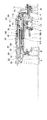
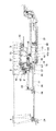
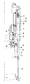
焦点距離18mm〜270mmのインナーフォーカス方式のズームレンズ鏡筒10は、図1及び図2に示すように、第1レンズ群A(焦点距離+108mm)、第2レンズ群B焦点距−13mm)、第3レンズ群C(焦点距離+45mm)、第4レンズ群D焦点距離+48mm)が装着される。第3レンズ群Cは、第3レンズ群前群Cf(焦点距離+27mm)及び手振れ防止のために光軸と直交する方向へシフトされる第3レンズ群後群Cr(焦点距離−40mm)からなる。ズームレンズ鏡筒10は、カメラボデー(図示せず)に取付けるためのマウント11と一体の固定筒12を有する。
The best embodiment of the inner focus zoom lens barrel of the present invention will be described below with reference to the drawings.
(Configuration of the lens barrel)
As shown in FIGS. 1 and 2, the zoom lens barrel 10 having an inner focus method with a focal length of 18 mm to 270 mm includes a first lens group A (focal length +108 mm), a second lens group B focal length −13 mm, Three lens groups C (focal length +45 mm) and fourth lens group D focal length +48 mm) are attached. The third lens group C includes a third lens group front group Cf (focal length +27 mm) and a third lens group rear group Cr (focal length −40 mm) shifted in a direction orthogonal to the optical axis to prevent camera shake. . The zoom lens barrel 10 has a fixed
固定筒12の内側には、フォーカスカム筒20、さらにその内側に直進筒18が配置されている。フォーカスカム筒20の内側には、直進筒18が配置されている。直進筒18の内側には、第1カム筒16、さらに内側に第2レンズ群レンズ枠2、第3レンズ群レンズ枠3、第4レンズ群レンズ枠4が配置されている。第3レンズ群レンズ枠3は、手振れ防止114を介して支持されている。第3レンズ群レンズ枠3及び第4レンズ群レンズ枠4は、第3レンズ群レンズ枠3の固着された第4レンズ群直進ガイドキー112によって、相互に光軸中心回転はしないが光軸方向の間隔を変更可能に連結されている。
A
固定筒12の外側には、ズーム連動リング14、その外側に第2カム筒22、さらにその外側に第1群レンズ摺動枠24が配置されている。第1群レンズ摺動枠24の外側すなわち外部に露出して、装飾用の外筒26、ズーム操作リング30、及びフォーカス操作リング28が配置されている。固定筒12の外側には、さらに、固定筒12と一体の中間鏡筒29、及びフォーカス操作リング28に固着されたフォーカス連動板102が設けられている。フォーカス連動板102の前側(マウント11と反対側)端部には、固定筒12のフォーカス連動コマ逃げ貫通孔104を貫通してフォーカスカム溝106に係合するフォーカス連動コマ83が植設されている。
A
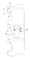
固定筒12は、図3に示すように、フォーカス連動板102に植設されたフォーカス連動コマ83が貫通するフォーカス連動コマ逃げ貫通孔104を有する。固定筒12の内面には、直進筒18に植設された直進筒ガイドコマ100が係合する直進ガイド溝47を有する。固定筒12の外面には、第1カム筒ガイドコマ39が植設されている。
As shown in FIG. 3, the fixed
フォーカスカム筒20には、図4に示すように、第2レンズ群フォーカスコマ96が係合する第2レンズ群フォーカスカム(2)27、第2レンズ群ガイドコマ74が係合する第2レンズ群フォーカスカム(1)79、及びフォーカス連動コマ83が係合するフォーカスカム溝106が設けられている。
As shown in FIG. 4, the second lens group focus cam (2) 27 to which the second lens
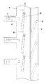
直進筒18は、図5に示すように、第2レンズ群ガイドコマ74が係合する第2レンズ群ガイドカム80、第2レンズ群フォーカスコマ96が係合する第2レンズ群ガイドカム(2)81、及び第1カム筒16に植設された第1カム筒回転ガイドコマ86が係合する第1カム筒回転溝88を有する。直進筒18はさらに、第3レンズ群枠3に植設された第3レンズ群ガイドコマ43が係合する第2縦ガイド溝61が設けられ、また直進筒ガイドコマ100が植設されている。直進筒18にはさらに、前端部に、第2カム筒22の横ガイド溝62に係合する第1レンズ群コマ66が固着されている。
As shown in FIG. 5, the
第1カム筒16は、図6に示すように、第3レンズ群ガイドコマ43が係合する第3レンズ群ガイドカム44、第4レンズ群ガイドコマ45が係合する第4レンズ群ガイドカム46、及び第2レンズ群ガイドコマ74が係合する第3縦ガイド溝48を有する。第1カム筒16には、さらに、第1カム筒回転ガイドコマ86が植設されている。
As shown in FIG. 6, the
ズーム連動リング14は、図7に示すように、固定筒12に植設された第1カム筒ガイドコマ39が係合するズーム連動リングガイドカム42を有する。ズーム連動リング14はまた、ズーム連動リングガイドコマ50が植設するための第1嵌合孔57を有する。ズーム連動リング14はまた、第2レンズ群ガイドコマ74を植設するための第2レンズ群ガイドコマ嵌合孔75が設けられている。ズーム連動リング14は、さらに、像側に突出するズーム連動ポスト31にズーム連動コマ40が装着されている。
As shown in FIG. 7, the
第2カム筒22は、図8に示すように、第1レンズ群ガイドコマ70が係合する第1レンズ群ガイドカム77、ズーム連動リングガイドコマ50が係合する第1縦ガイド溝60、及び第1レンズ群コマ66が係合する横ガイド溝62が設けられている。
As shown in FIG. 8, the
第1レンズ群摺動枠24には、図9に示すように、その内側図に、第1レンズ群コマ66が係合する第3縦ガイド溝64と、第2カム筒22の第1レンズ郡ガイドカム77に係合する第1レンズ群ガイドコマ70が設けられている。
As shown in FIG. 9, the first lens
(ズーム作動)
ズーム作動は、図1及び図2を参照して、ズームリング30を回転作動させる。ズームリング30の回転作動は、ズームリング30の光軸と平行に延びた直進溝(図示せず)に係合したズーム連動コマ40及びズーム連動ポスト31を介してズーム連動リング14に伝達される。
(Zoom operation)
The zoom operation rotates the
ズーム連動リング14が回転作動すると、固定筒12に植設された第1カム筒ガイドコマ39がズーム連動リング14の第1カム筒ガイドカム42に係合することにより、ズーム連動リング14は光軸方向移動及び回転作動する。
When the
ズーム連動リング14に内向きに植設された第2レンズ群ガイドコマ74が、フォーカスカム筒20の第2レンズ群フォーカスカム(1)79、直進筒18の第2レンズ群ガイドカム80、及び第1カム筒16の第3縦ガイド溝48に係合している。これらの嵌合により、フォーカスカム筒20は光軸方向移動及び回転作動し、直進筒18は光軸方向に直進移動し、第1カム筒16は回転作動する。
A second lens
ズーム連動リング14に外向きに植設されたズーム連動リングガイドコマ50が、第2カム筒22の第1縦ガイド溝60に係合していることにより、ズーム連動リング14の回転作動が第2カム筒22に伝達される。
Since the zoom interlocking
第1レンズ群Aのズーミング移動は、第1レンズ群コマ66と横ガイド溝62の係合により直進筒18の光軸方向移動が第2カム筒22に伝達され、さらに、回転規制された第2カム筒22の第1レンズ群ガイドカム77と第1レンズ群ガイドコマ70の係合により、第1群レンズ摺動枠24が第2カム筒22の上で光軸方向移動する。
In the zooming movement of the first lens group A, the movement of the
第2レンズ群Bのズーミング移動は、第2レンズ群レンズ枠2の第2レンズ群フォーカスコマ96と一緒に光軸方向移動及び回転作動する。
The zooming movement of the second lens group B is moved and rotated in the optical axis direction together with the second lens
第3レンズ群Cのズーミング移動は、第3レンズ群枠42に植設された第3レンズ群ガイドコマ43が、直進筒18の第2縦ガイド溝61及び第1カム筒16の第3レンズ群ガイドカム44に係合していることにより光軸方向移動する。
In the zooming movement of the third lens group C, the third lens
第4レンズ群Dのズーミング移動は、第4レンズ群枠4に植設された第4レンズ群ガイドコマ45が、第1カム筒16の第4レンズ群ガイドカム46に係合し、さらに第4レンズ群直進ガイドキー112が第4レンズ群枠4に光軸と平行に延びるように形成された回転止め溝(図示せず)との係合によって、光軸方向移動する。
In the zooming movement of the fourth lens group D, the fourth lens
(フォーカス作動)
フォーカスリング28の回転作動は、図1及び図2を参照して、フォーカスギヤリング94及びフォーカス連動板102を介して、フォーカスカム筒20に伝達される。フォーカスカム筒20の回転作動は、静止している第2レンズ群ガイドコマ74を基準にしてなされる。すなわち、第2レンズ群ガイドコマ74の第2レンズ群フォーカスカム(1)79と直進筒18の第2レンズ群ガイドカム80との係合、及び第2レンズ群レンズ枠2の第2レンズ群フォーカスコマ96の第2レンズ群フォーカスカム(2)27と直進筒18の第2レンズ群ガイドカム(2)81との係合によって、光軸方向移動する。
(Focus operation)
The rotation operation of the focus ring 28 is transmitted to the
(変形例)
前記実施形態においては、第4レンズ群枠4の回転作動を第4レンズ群直進ガイドキー112によって規制している。第4レンズ群直進ガイドキー112に代えて、直進筒18を像側に延ばして第4レンズ群枠4に光軸と平行に延びるように形成された回転止め溝に係合させてもよい。
(Modification)
In the embodiment, the rotation operation of the fourth lens group frame 4 is regulated by the fourth lens group linear guide key 112. Instead of the fourth lens group rectilinear guide key 112, the
A 第1レンズ群
B 第2レンズ群
C 第3レンズ群
D 第4レンズ群
2 第2レンズ群レンズ枠
3 第3レンズ群レンズ枠
4 第4レンズ群レンズ枠
10 ズームレンズ鏡筒
11 マウント
12 固定筒
14 ズーム連動リング
16 第1カム筒
18 直進筒
20 フォーカスカム筒
22 第2カム筒
23 フォーカス連動リング
24 第1群レンズ摺動枠
26 外筒
27 第2レンズ群フォーカスガイド溝
28 フォーカス操作リング
29 中間鏡筒
30 ズーム操作リング
31 ズーム連動ポスト
40 ズーム連動コマ
43 第3レンズ群ガイドコマ
44 第3レンズ群ガイドカム
45 第4レンズ群ガイドコマ
46 第4レンズ群ガイドカム
47 直進ガイド溝
50 ズーム連動リングガイドコマ
56 第3レンズ群ガイドコマ嵌合孔
60 第1縦ガイド溝
61 第2縦ガイド溝
62 横ガイド溝
64 第3縦ガイド溝
66 第1レンズ群コマ
70 第1レンズ群ガイドコマ
74 第2レンズ群ガイドコマ
77 第1レンズ群ガイドカム
80 第2レンズ群ガイドカム
81 第2レンズ群ガイドカム(2)
83 フォーカス連動コマ
96 第2レンズ群フォーカスコマ
100 直進筒ガイドコマ
102 フォーカス連動板フォーカス連動板
104 フォーカス連動コマ逃げ貫通孔
106 フォーカスカム溝
112 第4レンズ群直進ガイドキー
114 手振れ防止機構
A First lens group B Second lens group C Third lens group D Fourth lens group 2 Second lens
83
Claims (4)
Priority Applications (3)
| Application Number | Priority Date | Filing Date | Title |
|---|---|---|---|
| JP2008206017A JP5266948B2 (en) | 2008-08-08 | 2008-08-08 | Inner focus zoom lens barrel |
| US12/318,592 US8305696B2 (en) | 2008-08-08 | 2008-12-31 | Inner focusing zoom lens |
| CN2009101433057A CN101644817B (en) | 2008-08-08 | 2009-05-19 | Inner focusing zoom lens and barrel thereof |
Applications Claiming Priority (1)
| Application Number | Priority Date | Filing Date | Title |
|---|---|---|---|
| JP2008206017A JP5266948B2 (en) | 2008-08-08 | 2008-08-08 | Inner focus zoom lens barrel |
Publications (2)
| Publication Number | Publication Date |
|---|---|
| JP2010044102A true JP2010044102A (en) | 2010-02-25 |
| JP5266948B2 JP5266948B2 (en) | 2013-08-21 |
Family
ID=41652695
Family Applications (1)
| Application Number | Title | Priority Date | Filing Date |
|---|---|---|---|
| JP2008206017A Expired - Fee Related JP5266948B2 (en) | 2008-08-08 | 2008-08-08 | Inner focus zoom lens barrel |
Country Status (3)
| Country | Link |
|---|---|
| US (1) | US8305696B2 (en) |
| JP (1) | JP5266948B2 (en) |
| CN (1) | CN101644817B (en) |
Cited By (3)
| Publication number | Priority date | Publication date | Assignee | Title |
|---|---|---|---|---|
| JP2015106128A (en) * | 2013-12-02 | 2015-06-08 | 株式会社タムロン | Zoom lens barrel |
| JP2016130760A (en) * | 2015-01-13 | 2016-07-21 | キヤノン株式会社 | Zoom lens barrel and optical device including the same |
| US10809490B2 (en) | 2017-06-02 | 2020-10-20 | Nikon Corporation | Lens barrel and imaging device |
Families Citing this family (6)
| Publication number | Priority date | Publication date | Assignee | Title |
|---|---|---|---|---|
| JP5592732B2 (en) * | 2010-09-02 | 2014-09-17 | オリンパスイメージング株式会社 | Zoom lens barrel |
| RU2650435C2 (en) * | 2011-11-11 | 2018-04-13 | Никон Корпорейшн | Focal point adjustment device, image capture device and lens barrel |
| JP2013164580A (en) * | 2012-01-13 | 2013-08-22 | Tamron Co Ltd | Zoom lens barrel |
| WO2017201724A1 (en) | 2016-05-27 | 2017-11-30 | SZ DJI Technology Co., Ltd. | System for balancing center of gravity of a zoom lens |
| CN108563004B (en) * | 2018-02-02 | 2024-01-05 | 中国科学院西安光学精密机械研究所 | Three-group linkage continuous zooming mechanism with high stability of optical axis |
| CN110543063B (en) * | 2019-06-26 | 2023-12-01 | 广州长步道光学科技有限公司 | Automatic focusing device and automatic focusing lens comprising same |
Citations (1)
| Publication number | Priority date | Publication date | Assignee | Title |
|---|---|---|---|---|
| JP2008152049A (en) * | 2006-12-18 | 2008-07-03 | Nikon Corp | Zoom lens, imaging apparatus, vibration-proof method for zoom lens, and method for varying power of zoom lens |
Family Cites Families (7)
| Publication number | Priority date | Publication date | Assignee | Title |
|---|---|---|---|---|
| US5172276A (en) * | 1989-08-29 | 1992-12-15 | Minolta Camera Kabushiki Kaisha | Structure for stabilizing image in optical system |
| JP3461224B2 (en) | 1995-04-28 | 2003-10-27 | 株式会社タムロン | High magnification zoom lens |
| JP2000089086A (en) | 1998-09-14 | 2000-03-31 | Sigma Corp | Zoom lens barrel |
| JP3689379B2 (en) | 2002-03-20 | 2005-08-31 | 株式会社タムロン | High magnification zoom lens |
| JP4882321B2 (en) | 2005-09-15 | 2012-02-22 | 株式会社ニコン | Lens barrel |
| JP4594867B2 (en) * | 2006-01-16 | 2010-12-08 | 株式会社タムロン | Downsizing zoom lens |
| JP4889519B2 (en) * | 2007-02-16 | 2012-03-07 | 株式会社タムロン | Inner focus zoom lens barrel |
-
2008
- 2008-08-08 JP JP2008206017A patent/JP5266948B2/en not_active Expired - Fee Related
- 2008-12-31 US US12/318,592 patent/US8305696B2/en not_active Expired - Fee Related
-
2009
- 2009-05-19 CN CN2009101433057A patent/CN101644817B/en not_active Expired - Fee Related
Patent Citations (1)
| Publication number | Priority date | Publication date | Assignee | Title |
|---|---|---|---|---|
| JP2008152049A (en) * | 2006-12-18 | 2008-07-03 | Nikon Corp | Zoom lens, imaging apparatus, vibration-proof method for zoom lens, and method for varying power of zoom lens |
Cited By (5)
| Publication number | Priority date | Publication date | Assignee | Title |
|---|---|---|---|---|
| JP2015106128A (en) * | 2013-12-02 | 2015-06-08 | 株式会社タムロン | Zoom lens barrel |
| WO2015083703A1 (en) * | 2013-12-02 | 2015-06-11 | 株式会社タムロン | Zoom lens barrel |
| JP2016130760A (en) * | 2015-01-13 | 2016-07-21 | キヤノン株式会社 | Zoom lens barrel and optical device including the same |
| US10809490B2 (en) | 2017-06-02 | 2020-10-20 | Nikon Corporation | Lens barrel and imaging device |
| US11320627B2 (en) | 2017-06-02 | 2022-05-03 | Nikon Corporation | Lens barrel and imaging device |
Also Published As
| Publication number | Publication date |
|---|---|
| US20100033845A1 (en) | 2010-02-11 |
| CN101644817A (en) | 2010-02-10 |
| US8305696B2 (en) | 2012-11-06 |
| CN101644817B (en) | 2012-01-04 |
| JP5266948B2 (en) | 2013-08-21 |
Similar Documents
| Publication | Publication Date | Title |
|---|---|---|
| JP5266948B2 (en) | Inner focus zoom lens barrel | |
| JP4889519B2 (en) | Inner focus zoom lens barrel | |
| JP4594867B2 (en) | Downsizing zoom lens | |
| EP1780567A4 (en) | Electronic imaging device | |
| JP2013120357A (en) | Interchangeable lens | |
| JP3689379B2 (en) | High magnification zoom lens | |
| JP2004258642A (en) | Cam mechanism for lens barrel | |
| JP2009025366A5 (en) | ||
| US7876508B2 (en) | Lens drive unit, lens barrel, and image forming device | |
| EP2693247A1 (en) | Mechanism for moving optical element | |
| JP6090132B2 (en) | Zoom lens barrel | |
| JP2005352406A (en) | Zoom lens barrel | |
| JP2002311322A (en) | High zoom ratio lens | |
| JP2011039408A (en) | Inner focus zoom lens | |
| JP6544598B2 (en) | Lens barrel | |
| JP2009244719A (en) | Optical device and imaging apparatus | |
| JP2007333764A (en) | Lens barrel and camera | |
| JP2007003581A (en) | Lens barrel | |
| JP4766973B2 (en) | Lens barrel and lens system | |
| JP2006215421A (en) | Lens barrel | |
| JP5287714B2 (en) | Lens barrel and camera | |
| JP2005352407A (en) | Projection lens barrel | |
| JP2001215398A (en) | Zoom camera | |
| JP2005084406A (en) | Zoom lens barrel and optical equipment | |
| JP2010008634A (en) | Lens barrel |
Legal Events
| Date | Code | Title | Description |
|---|---|---|---|
| A621 | Written request for application examination |
Free format text: JAPANESE INTERMEDIATE CODE: A621 Effective date: 20110518 |
|
| A977 | Report on retrieval |
Free format text: JAPANESE INTERMEDIATE CODE: A971007 Effective date: 20111221 |
|
| A131 | Notification of reasons for refusal |
Free format text: JAPANESE INTERMEDIATE CODE: A131 Effective date: 20120110 |
|
| A521 | Written amendment |
Free format text: JAPANESE INTERMEDIATE CODE: A523 Effective date: 20120309 |
|
| A131 | Notification of reasons for refusal |
Free format text: JAPANESE INTERMEDIATE CODE: A131 Effective date: 20120820 |
|
| A521 | Written amendment |
Free format text: JAPANESE INTERMEDIATE CODE: A523 Effective date: 20121017 |
|
| TRDD | Decision of grant or rejection written | ||
| A01 | Written decision to grant a patent or to grant a registration (utility model) |
Free format text: JAPANESE INTERMEDIATE CODE: A01 Effective date: 20130415 |
|
| A61 | First payment of annual fees (during grant procedure) |
Free format text: JAPANESE INTERMEDIATE CODE: A61 Effective date: 20130422 |
|
| R150 | Certificate of patent or registration of utility model |
Free format text: JAPANESE INTERMEDIATE CODE: R150 |
|
| LAPS | Cancellation because of no payment of annual fees |