JP2010044047A - Knocking sensor - Google Patents
Knocking sensor Download PDFInfo
- Publication number
- JP2010044047A JP2010044047A JP2009052337A JP2009052337A JP2010044047A JP 2010044047 A JP2010044047 A JP 2010044047A JP 2009052337 A JP2009052337 A JP 2009052337A JP 2009052337 A JP2009052337 A JP 2009052337A JP 2010044047 A JP2010044047 A JP 2010044047A
- Authority
- JP
- Japan
- Prior art keywords
- end side
- support
- engagement
- knocking sensor
- main body
- Prior art date
- Legal status (The legal status is an assumption and is not a legal conclusion. Google has not performed a legal analysis and makes no representation as to the accuracy of the status listed.)
- Granted
Links
Images

Classifications
-
- G—PHYSICS
- G01—MEASURING; TESTING
- G01L—MEASURING FORCE, STRESS, TORQUE, WORK, MECHANICAL POWER, MECHANICAL EFFICIENCY, OR FLUID PRESSURE
- G01L23/00—Devices or apparatus for measuring or indicating or recording rapid changes, such as oscillations, in the pressure of steam, gas, or liquid; Indicators for determining work or energy of steam, internal-combustion, or other fluid-pressure engines from the condition of the working fluid
- G01L23/22—Devices or apparatus for measuring or indicating or recording rapid changes, such as oscillations, in the pressure of steam, gas, or liquid; Indicators for determining work or energy of steam, internal-combustion, or other fluid-pressure engines from the condition of the working fluid for detecting or indicating knocks in internal-combustion engines; Units comprising pressure-sensitive members combined with ignitors for firing internal-combustion engines
- G01L23/221—Devices or apparatus for measuring or indicating or recording rapid changes, such as oscillations, in the pressure of steam, gas, or liquid; Indicators for determining work or energy of steam, internal-combustion, or other fluid-pressure engines from the condition of the working fluid for detecting or indicating knocks in internal-combustion engines; Units comprising pressure-sensitive members combined with ignitors for firing internal-combustion engines for detecting or indicating knocks in internal combustion engines
- G01L23/222—Devices or apparatus for measuring or indicating or recording rapid changes, such as oscillations, in the pressure of steam, gas, or liquid; Indicators for determining work or energy of steam, internal-combustion, or other fluid-pressure engines from the condition of the working fluid for detecting or indicating knocks in internal-combustion engines; Units comprising pressure-sensitive members combined with ignitors for firing internal-combustion engines for detecting or indicating knocks in internal combustion engines using piezoelectric devices
Landscapes
- Chemical & Material Sciences (AREA)
- Engineering & Computer Science (AREA)
- Combustion & Propulsion (AREA)
- Physics & Mathematics (AREA)
- General Physics & Mathematics (AREA)
- Measuring Fluid Pressure (AREA)
- Measurement Of Mechanical Vibrations Or Ultrasonic Waves (AREA)
Abstract
Description
本発明は、内燃機関のエンジンブロック等に取り付けられ、内燃機関で発生するノッキングを検知するノッキングセンサに関し、特に、圧電素子と、これを支持する支持部材と、圧電素子及び支持部材の少なくとも一部を覆う樹脂被覆体とを備えるノッキングセンサに関する。 The present invention relates to a knocking sensor that is attached to an engine block or the like of an internal combustion engine and detects knocking that occurs in the internal combustion engine, and in particular, a piezoelectric element, a support member that supports the piezoelectric element, and at least a part of the piezoelectric element and the support member. The present invention relates to a knocking sensor including a resin coating covering the surface.
従来より、内燃機関のエンジンブロック等に取り付けられ、内燃機関で発生するノッキングを検知するノッキングセンサが知られている。例えば、特許文献1,2に、このようなノッキングセンサが開示されている。
特許文献1のノックセンサ(ノッキングセンサ)は、筒状の圧力スリーブ(挿通部)とこの基端に設けられたフランジ状の鍔部(支持本体部)とからなる支持部材を備える(特許文献1の図1及びその説明箇所等を参照)。圧力スリーブの外周には、圧電セラミックプレート(圧電素子)やコンタクトプレート、絶縁プレート、質量体等が配置され、鍔部によって支持されている。そして、圧電セラミックプレート等は、モールド成形されたプラスチックケース(樹脂被覆体)により覆われてシールされている。
Conventionally, a knocking sensor that is attached to an engine block or the like of an internal combustion engine and detects knocking that occurs in the internal combustion engine is known. For example,
The knock sensor (knocking sensor) of
このノックセンサでは、支持部材とプラスチックケースとのシール性を向上させるために、支持部材のうち、圧力スリーブの先端側外周に2本の溝を周設している。また、鍔部の外周にも2本の溝を周設している。 In this knock sensor, in order to improve the sealing performance between the support member and the plastic case, two grooves are provided around the outer periphery of the front end side of the pressure sleeve in the support member. Two grooves are also provided on the outer periphery of the collar.
特許文献2のノックセンサ(ノッキングセンサ)は、円筒状の筒部(挿通部)とこの基端に設けられた鍔部(支持本体部)とからなる筒状芯金(支持部材)を備える(特許文献2の図1及びその説明箇所等を参照)。筒部の外周には、圧電素子や電極板、絶縁板、ウェイト等が配置され、鍔部によって支持されている。そして、圧電素子等は、モールド成形された樹脂被覆体により覆われてシールされている。 The knock sensor (knocking sensor) of Patent Document 2 includes a cylindrical cored bar (supporting member) composed of a cylindrical cylindrical part (insertion part) and a collar part (supporting main body part) provided at the base end ( (See FIG. 1 of Patent Document 2 and the explanation thereof). Piezoelectric elements, electrode plates, insulating plates, weights, and the like are disposed on the outer periphery of the cylindrical portion and supported by the flange portion. The piezoelectric element or the like is covered and sealed with a molded resin coating.
このノックセンサでも、筒状芯金と樹脂被覆体とのシール性を向上させるために、金属芯金のうち、筒部の先端側外周に2本の溝を周設している。また、鍔部の外周にも2本の溝を周設している。更に、このノックセンサでは、各々の溝の形態を、径方向外側に向かうにつれて軸線方向の幅が漸減する形態とすることで、各溝に入り込んだ樹脂を抜け難くし、樹脂被覆体を剥がれ難くしている。 Also in this knock sensor, in order to improve the sealing performance between the cylindrical cored bar and the resin coating, two grooves are provided in the outer periphery of the tip side of the cylindrical part of the metal cored bar. Two grooves are also provided on the outer periphery of the collar. Furthermore, in this knock sensor, the shape of each groove is such that the width in the axial direction gradually decreases toward the outside in the radial direction, making it difficult for the resin that has entered each groove to come off and the resin cover to be peeled off. is doing.
しかしながら、特許文献1のノックセンサのみならず、筒状芯金と樹脂被覆体とのシール性を改良した特許文献2のノックセンサでも、依然として十分なシールの耐久性を確保することが困難であった。しかも、特許文献2のノックセンサは、上記溝の加工が難しいという問題もある。
However, not only the knock sensor of
本発明は、かかる現状に鑑みてなされたものであって、支持部材と樹脂被覆体とのシールの耐久性を向上させることができるノッキングセンサを提供することを目的とする。 This invention is made | formed in view of this present condition, Comprising: It aims at providing the knocking sensor which can improve the durability of the seal | sticker of a support member and a resin coating body.
その解決手段は、圧電素子と、前記圧電素子を直接又は間接に支持する支持面を含む支持本体部を有する支持部材と、前記支持面に直交する直交方向のうち、前記支持面が向く側を先端側、これとは反対側を基端側とし、前記支持面に沿う沿面方向のうち、前記圧電素子及び前記支持本体部の外側を向く側を沿面方向外側、前記圧電素子及び前記支持本体部の内側を向く側を沿面方向内側としたとき、前記圧電素子、及び、前記支持部材の少なくとも一部を覆う樹脂被覆体であって、前記圧電素子の外周及び前記支持本体部の外周を覆う外側部を有する樹脂被覆体と、を備えるノッキングセンサであって、前記支持部材の前記支持本体部は、自身の前記基端側に第1係合部を有し、前記樹脂被覆体は、前記外側部に連なって前記沿面方向内側に延びて、前記支持本体部の前記基端側に回り込む回り込み部であって、前記第1係合部と互いに係合する第2係合部を含む回り込み部を有するノッキングセンサである。 The solving means includes a piezoelectric element, a support member having a support main body portion including a support surface that directly or indirectly supports the piezoelectric element, and a direction in which the support surface faces in an orthogonal direction orthogonal to the support surface. The tip side, the opposite side is the base end side, and the side facing the outside of the piezoelectric element and the support main body portion in the creeping direction along the support surface is the creeping direction outer side, and the piezoelectric element and the support main body portion A resin coating covering at least a part of the piezoelectric element and the support member when the side facing the inner side is a creeping direction inner side, and covering the outer periphery of the piezoelectric element and the outer periphery of the support body part A knocking sensor comprising: a resin cover having a first portion, wherein the support body portion of the support member has a first engagement portion on the base end side of the support member; Inside the creeping direction connected to the section Extending the support an the proximal side goes around curved portion of the main body, a knock sensor having a curved portion including a second engagement portion engaged with each other with said first engaging portion.
従来技術に係るノッキングセンサにおいては、樹脂被覆体を構成する樹脂材料に経年劣化が進行すると、樹脂被覆体のうち圧電素子や支持部材の支持本体部の外周を覆う外側部が、支持本体部の外周の下側(基端側)から剥がれて、樹脂被覆体の外側部と支持本体部の外周との間に隙間が生じることがあった。この理由は、以下のものと考えられる。ノッキングセンサが高温環境下に長期間晒されたり、冷熱サイクルの繰り返しにあうと、樹脂被覆体を構成する樹脂材料に経年劣化が進行し、樹脂被覆体に収縮(所謂、熱やせ)が生じるが、この収縮はノッキングセンサの構造上、主に外側部の支持面に直交する直交方向に大きく生じる。特に、上記直交方向に沿った方向の外側部の寸法(高さ)が大きいほど、収縮の程度が大きくなる傾向にある。そして、樹脂被覆体(外側部)が上記略直交方向に収縮すると、支持本体部の外周に設けられた溝に入り込んだ外側部の一部が溝から抜ける方向に移動してしまい、樹脂被覆体のうち支持本体部の外周を覆う外側部が、支持本体部の外周の下側(基端側)から剥がれてしまうのである。そこで、本発明者は、樹脂被覆体の外側部における収縮に対しても、樹脂被覆体と支持部材とのシール性を十分に維持できるノッキングセンサを鋭意検討して、本発明に至った。 In the knocking sensor according to the prior art, when the aging of the resin material constituting the resin cover progresses, the outer portion of the resin cover covering the outer periphery of the support body portion of the piezoelectric element or the support member is the support body portion. It may peel off from the lower side (base end side) of the outer periphery, and a gap may be generated between the outer portion of the resin coating and the outer periphery of the support main body. The reason is considered as follows. When the knocking sensor is exposed to a high temperature environment for a long period of time or repeatedly subjected to a cooling / heating cycle, the resin material constituting the resin coating body deteriorates over time, and the resin coating body shrinks (so-called heat loss). This contraction largely occurs in the orthogonal direction orthogonal to the support surface of the outer portion mainly due to the structure of the knocking sensor. In particular, the degree of contraction tends to increase as the dimension (height) of the outer portion in the direction along the orthogonal direction increases. When the resin cover (outer part) contracts in the substantially orthogonal direction, a part of the outer part that has entered the groove provided on the outer periphery of the support main body part moves in a direction to escape from the groove, and the resin cover. The outer part which covers the outer periphery of a support main-body part will peel from the lower side (base end side) of the outer periphery of a support main-body part. Therefore, the inventor has intensively studied a knocking sensor capable of sufficiently maintaining the sealing performance between the resin coating and the support member against the contraction of the outer portion of the resin coating, and has reached the present invention.
即ち、本発明のノッキングセンサでは、樹脂被覆体に、その外側部に連なり、支持部材の支持本体部の基端側に回り込む回り込み部を設けている。このノッキングセンサによれば、樹脂被覆体を構成する樹脂材料に経年劣化が進行し、樹脂被覆体(特に外側部)に、支持面に直交する直交方向への収縮が生じても、外側部に連なる回り込み部が支持本体部の基端側に位置することにより、外側部の上記略直交方向の収縮が制限される。 In other words, in the knocking sensor of the present invention, the resin cover is provided with a wraparound portion that extends to the outer side of the resin cover and goes around to the base end side of the support main body portion of the support member. According to this knocking sensor, even if the resin material constituting the resin coating body deteriorates over time, and the resin coating body (particularly the outer portion) contracts in the orthogonal direction perpendicular to the support surface, When the continuous wraparound portion is located on the base end side of the support main body portion, the contraction of the outer portion in the substantially orthogonal direction is limited.
更に、本発明では、支持本体部の基端側に第1係合部を設け、回り込み部に第1係合部と互いに係合する第2係合部を設けている。これにより、外側部の上記略直交方向への収縮が少なからず生じても、支持本体部に対する回り込み部の沿面方向外側への相対的な移動を、第1,第2係合部同士の互いの係合により抑制することができる。
従って、本発明によれば、外側部に連なる回り込み部を支持本体部の基端側に位置させてなることによる効果と、回り込み部に、支持本体部の基端側の第1係合部に係合する第2係合部を設けたことによる効果とが相俟って、樹脂被覆体(特に外側部)に経年変化に起因する収縮が生じたとしても、樹脂被覆体が支持本体部の外周から剥がれることを効果的に防止できる。その結果、支持部材と樹脂被覆体とのシールの耐久性を従来よりも向上させることができる。
Further, in the present invention, the first engagement portion is provided on the proximal end side of the support main body portion, and the second engagement portion that engages with the first engagement portion is provided in the wraparound portion. As a result, even if the outer portion contracts in the substantially orthogonal direction to some extent, the relative movement of the wraparound portion to the outer side in the creeping direction with respect to the support main body portion can be performed between the first and second engaging portions. It can be suppressed by engagement.
Therefore, according to the present invention, the wraparound portion connected to the outer portion is positioned on the base end side of the support body portion, and the wraparound portion is connected to the first engagement portion on the base end side of the support body portion. Combined with the effect of providing the second engaging portion to be engaged, even if the resin cover (especially the outer portion) contracts due to aging, the resin cover does not It can prevent effectively peeling from the outer periphery. As a result, the durability of the seal between the support member and the resin coating can be improved as compared with the conventional case.
なお、「支持部材」の形態としては、例えば、支持面を含む環状の支持本体部のみからなるものや、支持面を含む環状の支持本体部の他に、環状の圧電素子の内側を挿通する筒状の筒状部(挿通部)を設けたものなどが挙げられる。また、「支持部材」の材質は、内燃機関の振動に対する剛性などを考慮して適宜選択すればよく、例えば、金属やセラミック、樹脂等から適切な材質を選択すればよい。
また、「支持部材」は、その支持面により直接又は間接に圧電素子を支持するものである。間接に圧電素子を支持する形態としては、例えば、支持面と圧電素子との間に、電極部材や絶縁板等の他部材を介在させる形態が挙げられる。
In addition, as a form of the “support member”, for example, an inner portion of an annular piezoelectric element is inserted in addition to an annular support body portion including a support surface or an annular support body portion including a support surface. The thing provided with the cylindrical part (insertion part) etc. is mentioned. Further, the material of the “support member” may be appropriately selected in consideration of the rigidity with respect to vibration of the internal combustion engine, and for example, an appropriate material may be selected from metal, ceramic, resin, and the like.
In addition, the “support member” supports the piezoelectric element directly or indirectly by the support surface. Examples of the form of indirectly supporting the piezoelectric element include a form in which another member such as an electrode member or an insulating plate is interposed between the support surface and the piezoelectric element.
「樹脂被覆体」の材質は、支持部材とのシール性や耐熱性などを考慮して、適宜選択すればよい。また、「樹脂被覆体」としては、例えば、モールド成形されたものが挙げられる。
樹脂被覆体の「回り込み部」の形態としては、例えば、後述するように、支持本体部の外周に沿う環状に設けたものの他、支持本体部の外周に沿って断続的に複数設けたものなどが挙げられる。
The material of the “resin coating” may be appropriately selected in consideration of the sealing performance with the support member, heat resistance, and the like. In addition, examples of the “resin-coated body” include those molded.
As a form of the “wraparound portion” of the resin coating, for example, as described later, in addition to those provided in an annular shape along the outer periphery of the support main body portion, those provided intermittently along the outer periphery of the support main body portion, etc. Is mentioned.
支持部材の「第1係合部」及び樹脂被覆体の「第2係合部」は、支持部材と樹脂被覆体とのシールの耐久性等を考慮して、その形態を適宜変更できる。
例えば、「第1係合部」として、支持本体部の外周に沿う環状に形成され、或いは、支持本体部の外周に沿って複数並べて形成され、先端側に向けて凹み基端側に開口する溝状の係合溝部を設けることができる。そして、これに係合する「第2係合部」として、先端側に向けて突出し、上記係合溝部に入り込む係合突部を設けることができる。
The “first engagement portion” of the support member and the “second engagement portion” of the resin cover can be appropriately changed in consideration of the durability of the seal between the support member and the resin cover.
For example, as the “first engagement portion”, it is formed in an annular shape along the outer periphery of the support main body portion, or is formed side by side along the outer periphery of the support main body portion, and opens toward the distal end side toward the proximal end side. A groove-like engagement groove can be provided. As the “second engaging portion” that engages with this, it is possible to provide an engaging protrusion that protrudes toward the distal end side and enters the engaging groove.
また、「第1係合部」として、支持本体部の外周に沿う環状に形成され、或いは、支持本体部の外周に沿って複数並べて形成され、基端側に向けて突出する係合突部を設けることができる。そして、これに係合する「第2係合部」として、基端側に向けて凹み先端側に開口する溝状で、上記係合突部が入り込む係合溝部を設けることができる。 In addition, as the “first engagement portion”, an engagement protrusion that is formed in an annular shape along the outer periphery of the support main body portion, or is formed side by side along the outer periphery of the support main body portion, and protrudes toward the base end side. Can be provided. As a “second engagement portion” that engages with this, an engagement groove portion that is recessed toward the proximal end side and opens toward the distal end side and into which the engagement protrusion portion enters can be provided.
また、「第1係合部」として、支持本体部の外周に沿う環状に形成され、或いは、支持本体部の外周に沿って複数並べて形成され、沿面方向内側に向かうにつれて先端側に向けて大きく凹む係合テーパ状凹部を設けることができる。そして、これに係合する「第2係合部」として、沿面方向内側に向かうにつれて先端側に向けて大きく突出し、上記係合テーパ状凹部に入り込む係合テーパ状凸部を設けることができる。
また、「第1係合部」及び「第2係合部」として、上記の係合溝部、係合突部、係合テーパ状凹部及び係合テーパ状凸部のうち、2種以上を組み合わせて設けることもできる。
なお、後述する「第3係合部」及び「第4係合部」の形態についても、「第1係合部」及び「第2係合部」と同様である。
Further, as the “first engagement portion”, it is formed in an annular shape along the outer periphery of the support main body portion, or formed in a plurality along the outer periphery of the support main body portion, and increases toward the tip side as it goes in the creeping direction inside. An engagement tapered recess that is recessed can be provided. Then, as the “second engaging portion” that engages with this, it is possible to provide an engaging tapered convex portion that protrudes greatly toward the distal end side toward the inside in the creeping direction and enters the engaging tapered concave portion.
Further, as the “first engagement portion” and the “second engagement portion”, two or more of the above-mentioned engagement groove portions, engagement protrusions, engagement tapered concave portions, and engagement tapered convex portions are combined. It can also be provided.
Note that “third engagement portion” and “fourth engagement portion” to be described later are also the same as “first engagement portion” and “second engagement portion”.
更に、上記のノッキングセンサであって、前記回り込み部を、前記支持本体部の外周に沿う環状に設けてなるノッキングセンサとすると良い。 Further, in the above knock sensor, the wraparound portion may be a knock sensor provided in an annular shape along the outer periphery of the support main body portion.
本発明のノッキングセンサでは、回り込み部を、支持本体部の外周に沿う環状に設けているので、これに連なる外側部は、全周にわたって支持面に直交する直交方向の収縮が制限される。従って、外側部が支持本体部の外周から剥がれることを更に確実に防止できるので、支持部材と樹脂被覆体とのシールの耐久性を更に向上させることができる。 In the knocking sensor of the present invention, since the wraparound portion is provided in an annular shape along the outer periphery of the support main body portion, contraction in the orthogonal direction perpendicular to the support surface is limited over the entire outer portion. Therefore, since it can prevent more reliably that an outer side part peels from the outer periphery of a support main-body part, durability of the seal | sticker of a support member and a resin coating body can be improved further.
更に、上記のノッキングセンサであって、前記沿面方向に見て、前記回り込み部のうち、前記外側部の内周から前記回り込み部の内側端までの最短の回り込み長さを、前記外側部の厚みの、0.3倍以上6倍以下としてなるノッキングセンサとすると良い。 Further, in the above knocking sensor, the shortest wraparound length from the inner periphery of the outer portion to the inner end of the wrap portion of the wrap portion when viewed in the creeping direction is the thickness of the outer portion. The knocking sensor is preferably 0.3 times or more and 6 times or less.
本発明のノッキングセンサでは、樹脂被覆体のうち、回り込み部の回り込み長さを、外側部の厚みの0.3倍以上6倍以下としている。このようにすることで、この回り込み部が支持本体部から剥がれることを更に効果的に防止できるので、支持部材と樹脂被覆体とのシールの耐久性を更に向上させることができる。 In the knocking sensor of the present invention, the wraparound length of the wraparound portion of the resin coating is set to be not less than 0.3 times and not more than 6 times the thickness of the outer portion. By doing in this way, since it can prevent more effectively that this wraparound part peels from a support main-body part, durability of the seal | sticker of a support member and a resin coating body can be improved further.
更に、上記のいずれか記載のノッキングセンサであって、前記第1係合部は、前記先端側に向けて凹み前記基端側に開口する溝状で、前記支持本体部の外周に沿う環状に形成されてなる第1係合環状溝部であり、前記第2係合部は、前記先端側に向けて突出する環形突条状で、前記第1係合環状溝部内に入り込んでなる第2係合環状突部であるノッキングセンサとすると良い。 Furthermore, in the knocking sensor according to any one of the above, the first engagement portion is a groove shape that is recessed toward the distal end side and opens toward the proximal end side, and is annularly formed along an outer periphery of the support main body portion. A first engagement annular groove formed, and the second engagement part is a ring-shaped protrusion projecting toward the distal end side, and enters the first engagement annular groove. It is preferable to use a knocking sensor that is a combined annular protrusion.
本発明のノッキングセンサでは、第1係合部が上述の第1係合環状溝部であり、第2係合部がこの第1係合環状溝部内に入り込む上述の第2係合環状突部であるので、全周にわたり第1係合部と第2係合部とを互いに係合させることができる。しかも、溝部に突部を入り込ませて係合させているので、第1係合部と第2係合部とを確実に係合させることができる。従って、回り込み部が沿面方向外側に移動して支持本体部から剥がれることを更に効果的に防止できるので、支持部材と樹脂被覆体とのシールの耐久性を更に向上させることができる。 In the knocking sensor of the present invention, the first engagement portion is the above-described first engagement annular groove portion, and the second engagement portion is the above-described second engagement annular protrusion that enters the first engagement annular groove portion. Therefore, the first engagement portion and the second engagement portion can be engaged with each other over the entire circumference. Moreover, since the protrusion is inserted into the groove and engaged, the first engaging portion and the second engaging portion can be reliably engaged. Therefore, it is possible to more effectively prevent the wraparound portion from moving outward in the creeping direction and being peeled off from the support main body, so that the durability of the seal between the support member and the resin coating can be further improved.
更に、上記のいずれかに記載のノッキングセンサであって、前記支持本体部は、自身の基端に位置して前記基端側を向く基端面であって、前記樹脂被覆体に覆われることなく露出してなる基端面を有するノッキングセンサとすると良い。 Furthermore, in the knocking sensor according to any one of the above, the support main body portion is a base end surface that is located at a base end of the support body and faces the base end side, and is not covered with the resin coating body. A knocking sensor having a base end surface that is exposed may be used.
本発明のノッキングセンサでは、樹脂被覆体が支持本体部の基端側に回り込む回り込み部を有するにも拘わらず、支持本体部の基端面は樹脂被覆体(回り込み部等)に覆われることなく露出する形態としている。このため、このノッキングセンサを内燃機関のエンジンブロック等に取り付ける際に、支持本体部の基端面を、樹脂被覆体を介在させることなく、エンジンブロック等の取付部に直接当接させることができる。これにより、内燃機関で生じる振動がノッキングセンサに伝わりやすくなるので、ノッキングをより精度良く検知できる。 In the knocking sensor of the present invention, the base end surface of the support main body is exposed without being covered by the resin cover (such as the wraparound) even though the resin cover has a wraparound portion that wraps around the base end of the support main body. It is in the form to do. For this reason, when this knocking sensor is attached to the engine block or the like of the internal combustion engine, the base end surface of the support main body can be brought into direct contact with the attachment part such as the engine block without interposing a resin coating. As a result, vibration generated in the internal combustion engine is easily transmitted to the knocking sensor, so that knocking can be detected with higher accuracy.
また、他の解決手段は、環状をなす圧電素子と、前記圧電素子を直接又は間接に支持する支持面を含む支持本体部、及び、この支持本体部から延びて前記圧電素子内に挿通される挿通部を有する支持部材と、前記支持面に直交する直交方向のうち、前記支持面が向く側を先端側、これとは反対側を基端側とし、前記支持面に沿う沿面方向のうち、前記圧電素子及び前記支持本体部の外側を向く側を沿面方向外側、前記圧電素子及び前記支持本体部の内側を向く側を沿面方向内側としたとき、前記圧電素子、及び、前記支持部材の少なくとも一部を覆う樹脂被覆体であって、前記圧電素子の外周及び前記支持本体部の外周を覆う外側部、並びに、この外側部の前記先端側に連なり前記挿通部の外周先端側を覆う先端側部を有する樹脂被覆体と、を備えるノッキングセンサであって、前記支持部材及び前記樹脂被覆体は、前記支持本体部の前記基端側に設けられた第1係合部と、前記外側部に連なって前記沿面方向内側に延びて、前記支持本体部の前記基端側に回り込む基端側回り込み部であって、前記第1係合部と互いに係合する第2係合部を含む基端側回り込み部との組み合わせ、及び、前記挿通部の前記先端側に設けられた第3係合部と、前記先端側部に含まれ、前記沿面方向内側に延びて、前記挿通部の前記先端側に回り込む先端側回り込み部であって、前記第3係合部と互いに係合する第4係合部を含む先端側回り込み部との組み合わせ、の少なくともいずれかを有するノッキングセンサである。 Another solution is to provide a ring-shaped piezoelectric element, a support main body including a support surface that directly or indirectly supports the piezoelectric element, and an extension from the support main body to be inserted into the piezoelectric element. Of the orthogonal direction perpendicular to the support surface, the support member having an insertion portion, and the side facing the support surface is the distal end side, the opposite side is the base end side, and the creeping direction along the support surface, When the side facing the outside of the piezoelectric element and the support body portion is the creeping direction outside, and the side facing the inside of the piezoelectric element and the support body portion is the creeping direction inside, at least the piezoelectric element and the support member A resin cover that covers a part of the outer periphery of the piezoelectric element and the outer periphery of the support main body, and a distal end side that is connected to the distal end of the outer portion and covers the outer distal end of the insertion portion A resin coating having a portion; The knocking sensor is provided, wherein the support member and the resin coating body extend to the inside in the creeping direction continuously to the first engagement portion provided on the base end side of the support main body portion and the outer side portion. A combination of a base end side wraparound portion that wraps around the base end side of the support main body portion, including a second engagement portion that engages with the first engagement portion, and A third engagement portion provided on the distal end side of the insertion portion; and a distal end wrap portion included in the distal end side portion, extending inward in the creeping direction and wrapping around the distal end side of the insertion portion. A knock sensor having at least one of a combination of the third engagement portion and a distal end side wraparound portion including a fourth engagement portion that engages with each other.
従来技術に係るノッキングセンサにおいては、樹脂被覆体を構成する樹脂材料に経年劣化が進行すると、樹脂被覆体のうち圧電素子や支持部材の外周を覆う外側部が、支持部材のうちの支持本体部の外周の下側(基端側)から剥がれて、樹脂被覆体の外側部と支持本体部の外周との間に隙間が生じることがあった。或いは、樹脂被覆体の先端側部が、支持部材のうちの挿通部の外周先端側から剥がれて、樹脂被覆体の先端側部と挿通部の外周先端側との間に隙間が生じることがあった。この理由は、前述した通りである。 In the knocking sensor according to the prior art, when the aging of the resin material constituting the resin cover progresses, the outer part covering the outer periphery of the piezoelectric element and the support member in the resin cover is the support main body part of the support member. It peeled from the lower side (base end side) of the outer periphery, and a gap might be formed between the outer portion of the resin coating and the outer periphery of the support body portion. Alternatively, the front end side portion of the resin cover may be peeled off from the outer peripheral front end side of the insertion portion of the support member, and a gap may be formed between the front end side portion of the resin cover and the outer peripheral front end side of the insertion portion. It was. The reason is as described above.
これに対し、本発明のノッキングセンサでは、樹脂被覆体に、その外側部に連なり、支持部材の支持本体部の基端側に回り込む基端側回り込み部、及び、外側部に連なる先端側部に含まれ、支持部材の挿通部の先端側に回り込む先端側回り込み部の少なくともいずれかを設けている。このノッキングセンサによれば、樹脂被覆体を構成する樹脂材料に経年劣化が進行し、樹脂被覆体(特に外側部)に、支持面に直交する直交方向への収縮が生じても、外側部に連なる基端側回り込み部が支持本体部の基端側に位置することにより、外側部の上記略直交方向の収縮が制限される。或いは、外側部に連なる先端側部の先端側回り込み部が挿通部の先端側に位置することにより、外側部の上記略直交方向の収縮が制限される。 On the other hand, in the knocking sensor of the present invention, the resin cover is connected to the outer side portion thereof, to the base end side wrapping portion that wraps around the base end side of the support main body portion of the support member, and to the distal end side portion continuous to the outer side portion. It is included, and at least one of the distal end side wraparound portions that wrap around the distal end side of the insertion portion of the support member is provided. According to this knocking sensor, even if the resin material constituting the resin coating body deteriorates over time, and the resin coating body (particularly the outer portion) contracts in the orthogonal direction perpendicular to the support surface, When the base end side wrap-around portions that are continuous are located on the base end side of the support main body portion, the contraction of the outer portion in the substantially orthogonal direction is limited. Alternatively, the contraction in the substantially orthogonal direction of the outer portion is limited by the distal-side wraparound portion of the distal-side portion connected to the outer portion being positioned on the distal end side of the insertion portion.
更に、本発明では、支持本体部の基端側に第1係合部を設け、基端側回り込み部に第1係合部と互いに係合する第2係合部を設けている。或いは、挿通部の先端側に第3係合部を設け、先端側回り込み部に第3係合部と互いに係合する第4係合部を設けている。これにより、外側部の上記略直交方向への収縮が少なからず生じても、支持本体部に対する基端側回り込み部の沿面方向外側への相対的な移動を、第1,第2係合部同士の互いの係合により抑制することができる。或いは、挿通部に対する先端側回り込み部の沿面方向外側への相対的な移動を、第3,第4係合部同士の互いの係合により抑制することができる。 Further, in the present invention, the first engagement portion is provided on the proximal end side of the support main body portion, and the second engagement portion that engages with the first engagement portion is provided on the proximal end wraparound portion. Alternatively, a third engagement portion is provided on the distal end side of the insertion portion, and a fourth engagement portion that engages with the third engagement portion is provided on the distal end side wrap portion. As a result, even if the outer portion contracts in the substantially orthogonal direction, the relative movement of the proximal end wraparound portion to the outer side in the creeping direction with respect to the support main body portion can be performed between the first and second engaging portions. It can suppress by mutual engagement. Or the relative movement to the outer side of the creeping direction of the front end side wraparound portion with respect to the insertion portion can be suppressed by mutual engagement of the third and fourth engagement portions.
従って、本発明によれば、外側部に連なる基端側回り込み部を支持本体部の基端側に位置させてなることによる効果と、基端側回り込み部に、支持本体部の基端側の第1係合部に係合する第2係合部を設けたことによる効果とが相俟って、樹脂被覆体(特に外側部)に経年変化に起因する収縮が生じたとしても、樹脂被覆体が支持本体部の外周から剥がれることを効果的に防止できる。或いは、外側部に連なる先端側部の先端側回り込み部を挿通部の先端側に位置させてなることによる効果と、先端側回り込み部に、挿通部の先端側の第3係合部に係合する第4係合部を設けたことによる効果とが相俟って、樹脂被覆体(特に外側部)に経年変化に起因する収縮が生じたとしても、樹脂被覆体が挿通部の外周先端側から剥がれることを効果的に防止できる。
よって、支持部材と樹脂被覆体とのシールの耐久性を従来よりも向上させることができる。
Therefore, according to the present invention, the proximal end wraparound portion connected to the outer side portion is positioned on the proximal end side of the support main body portion, and the proximal end wraparound portion is connected to the proximal end side of the support main body portion. Combined with the effect of providing the second engagement portion that engages with the first engagement portion, even if the resin cover (especially the outer portion) contracts due to aging, the resin cover It can prevent effectively that a body peels from the outer periphery of a support main-body part. Alternatively, the tip side wrap around the tip side connected to the outer side is located on the tip side of the insertion part, and the tip side wrap part engages with the third engagement part on the tip side of the insertion part. Combined with the effect of providing the fourth engaging part, the resin cover (especially the outer part) may be contracted due to secular change, but the resin cover will be on the outer peripheral tip side of the insertion part. Can be effectively prevented from peeling off.
Therefore, the durability of the seal between the support member and the resin coating can be improved as compared with the conventional case.
なお、「基端側回り込み部」の形態としては、例えば、後述するように、支持本体部の外周に沿う環状に設けたものの他、支持本体部の外周に沿って断続的に複数設けたものなどが挙げられる。また、「先端側回り込み部」の形態としては、例えば、後述するように、挿通部の外周に沿う環状に設けたものの他、挿通部の外周に沿って断続的に複数設けたものなどが挙げられる。 In addition, as the form of the “base end side wrap portion”, for example, as described later, in addition to those provided in an annular shape along the outer periphery of the support main body portion, a plurality of intermittently provided along the outer periphery of the support main body portion Etc. In addition, examples of the form of the “tip-side wrap-around portion” include, for example, those provided in an annular shape along the outer periphery of the insertion portion, as well as those provided intermittently along the outer periphery of the insertion portion, as will be described later. It is done.
上記のノッキングセンサであって、前記支持部材及び前記樹脂被覆体は、前記第1係合部と前記基端側回り込み部との組み合わせを有するノッキングセンサとすると良い。
そして、前記基端側回り込み部を、前記支持本体部の外周に沿う環状に設けてなるノッキングセンサとすると良い。
It is said knock sensor, Comprising: It is good for the said supporting member and the said resin coating body to be a knock sensor which has a combination of a said 1st engaging part and the said base end side wraparound part.
And it is good to make the said base end side wraparound part into the knocking sensor formed in the cyclic | annular form along the outer periphery of the said support main-body part.
本発明のノッキングセンサでは、基端側回り込み部を、支持本体部の外周に沿う環状に設けているので、これに連なる外側部は、全周にわたって支持面に直交する直交方向の収縮が制限される。従って、外側部が支持本体部の外周から剥がれることを更に確実に防止できるので、支持部材と樹脂被覆体とのシールの耐久性を更に向上させることができる。 In the knocking sensor of the present invention, since the base end side wrap-around part is provided in an annular shape along the outer periphery of the support main body part, the outer part connected thereto is restricted from contracting in the orthogonal direction perpendicular to the support surface over the entire periphery. The Therefore, since it can prevent more reliably that an outer side part peels from the outer periphery of a support main-body part, durability of the seal | sticker of a support member and a resin coating body can be improved further.
更に、上記のノッキングセンサであって、前記沿面方向に見て、前記基端側回り込み部のうち、前記外側部の内周から前記基端側回り込み部の内側端までの最短の回り込み長さを、前記外側部の厚みの、0.3倍以上6倍以下としてなるノッキングセンサとすると良い。 Further, in the knocking sensor described above, the shortest wraparound length from the inner periphery of the outer portion to the inner end of the proximal wrap portion among the proximal wrap portions when viewed in the creeping direction. The knocking sensor may be 0.3 to 6 times the thickness of the outer portion.
本発明のノッキングセンサでは、樹脂被覆体のうち、基端側回り込み部の回り込み長さを、外側部の厚みの0.3倍以上6倍以下としている。このようにすることで、この基端側回り込み部が支持本体部から剥がれることを更に効果的に防止できるので、支持部材と樹脂被覆体とのシールの耐久性を更に向上させることができる。 In the knocking sensor of the present invention, the wraparound length of the proximal end wraparound portion of the resin coating is set to be not less than 0.3 times and not more than 6 times the thickness of the outer portion. By doing in this way, it can prevent more effectively that this base end side wraparound part peels off from a support main-body part, Therefore The durability of the seal | sticker of a support member and a resin coating body can be improved further.
更に、上記のノッキングセンサであって、前記第1係合部は、前記先端側に向けて凹み前記基端側に開口する溝状で、前記支持本体部の外周に沿う環状に形成されてなる第1係合環状溝部であり、前記第2係合部は、前記先端側に向けて突出する環形突条状で、前記第1係合環状溝部内に入り込んでなる第2係合環状突部であるノッキングセンサとすると良い。 Furthermore, in the knocking sensor described above, the first engagement portion is formed in an annular shape along the outer periphery of the support main body portion in a groove shape that is recessed toward the distal end side and opens toward the proximal end side. It is a 1st engagement cyclic | annular groove part, The said 2nd engagement part is the ring-shaped protrusion shape which protrudes toward the said front end side, The 2nd engagement cyclic | annular protrusion which enters in the said 1st engagement cyclic | annular groove part A knocking sensor that is
本発明のノッキングセンサでは、第1係合部が上述の第1係合環状溝部であり、第2係合部がこの第1係合環状溝部内に入り込む上述の第2係合環状突部であるので、全周にわたり第1係合部と第2係合部とを互いに係合させることができる。しかも、溝部に突部を入り込ませて係合させているので、第1係合部と第2係合部とを確実に係合させることができる。従って、基端側回り込み部が沿面方向外側に移動して支持本体部から剥がれることを更に効果的に防止できるので、支持部材と樹脂被覆体とのシールの耐久性を更に向上させることができる。 In the knocking sensor of the present invention, the first engagement portion is the above-described first engagement annular groove portion, and the second engagement portion is the above-described second engagement annular protrusion that enters the first engagement annular groove portion. Therefore, the first engagement portion and the second engagement portion can be engaged with each other over the entire circumference. Moreover, since the protrusion is inserted into the groove and engaged, the first engaging portion and the second engaging portion can be reliably engaged. Therefore, it is possible to more effectively prevent the base end side wrap-around portion from moving outward in the creeping direction and peeling off from the support main body portion, so that the durability of the seal between the support member and the resin coating can be further improved.
更に、上記のいずれかに記載のノッキングセンサであって、前記支持本体部は、自身の基端に位置して前記基端側を向く基端面であって、前記樹脂被覆体に覆われることなく露出してなる基端面を有するノッキングセンサとすると良い。 Furthermore, in the knocking sensor according to any one of the above, the support main body portion is a base end surface that is located at a base end of the support body and faces the base end side, and is not covered with the resin coating body. A knocking sensor having a base end surface that is exposed may be used.
本発明のノッキングセンサでは、樹脂被覆体が支持本体部の基端側に回り込む基端側回り込み部を有するにも拘わらず、支持本体部の基端面が、樹脂被覆体(基端側回り込み部等)に覆われることなく露出する形態としている。このため、このノッキングセンサを内燃機関のエンジンブロック等に取り付ける際に、支持本体部の基端面を、樹脂被覆体を介在させることなく、エンジンブロック等の取付部に直接当接させることができる。これにより、内燃機関で生じる振動がノッキングセンサに伝わりやすくなるので、ノッキングをより精度良く検知できる。 In the knocking sensor of the present invention, the base end surface of the support main body portion is not covered with the resin cover (base end side wrapping portion or the like) even though the resin cover has a base end side wraparound portion that wraps around the base end side of the support main body portion. ) To be exposed without being covered. For this reason, when this knocking sensor is attached to the engine block or the like of the internal combustion engine, the base end surface of the support main body can be brought into direct contact with the attachment part such as the engine block without interposing a resin coating. As a result, vibration generated in the internal combustion engine is easily transmitted to the knocking sensor, so that knocking can be detected with higher accuracy.
更に、上記のいずれかに記載のノッキングセンサであって、前記支持部材及び前記樹脂被覆体は、前記第3係合部と前記先端側回り込み部との組み合わせを有するノッキングセンサとすると良い。
そして、前記先端側回り込み部を、前記挿通部の外周に沿う環状に設けてなるノッキングセンサとすると良い。
Furthermore, in the knocking sensor according to any one of the above, the support member and the resin cover may be a knocking sensor having a combination of the third engagement portion and the distal end side wraparound portion.
And it is good to make the said front end side wrap-around part into the knock sensor provided in the cyclic | annular form along the outer periphery of the said insertion part.
本発明のノッキングセンサでは、先端側部の先端側回り込み部を、挿通部の外周に沿う環状に設けているので、先端側部に連なる外側部は、全周にわたって支持面に直交する直交方向の収縮が制限される。従って、先端側部が挿通部の外周先端側から剥がれることを更に確実に防止できるので、支持部材と樹脂被覆体とのシールの耐久性を更に向上させることができる。 In the knocking sensor of the present invention, since the tip side wraparound portion of the tip side portion is provided in an annular shape along the outer periphery of the insertion portion, the outer side portion connected to the tip side portion is orthogonal to the support surface over the entire circumference. Shrinkage is limited. Therefore, since it can prevent more reliably that a front end side part peels from the outer periphery front end side of an insertion part, durability of the seal | sticker of a support member and a resin coating body can be improved further.
更に、上記のノッキングセンサであって、前記第3係合部は、前記基端側に向けて凹み前記先端側に開口する溝状で、前記挿通部の外周に沿う環状に形成されてなる第3係合環状溝部であり、前記第4係合部は、前記基端側に向けて突出する環形突条状で、前記第3係合環状溝部内に入り込んでなる第4係合環状突部であるノッキングセンサとすると良い。 Further, in the above knocking sensor, the third engagement portion is formed in an annular shape along the outer periphery of the insertion portion, with a groove shape that is recessed toward the proximal end side and opens toward the distal end side. A fourth engaging annular protrusion, which is a three-engaged annular groove, and the fourth engaging part is a ring-shaped protrusion protruding toward the base end side and enters the third engaging annular groove. A knocking sensor that is
本発明のノッキングセンサでは、第3係合部が上述の第3係合環状溝部であり、第4係合部がこの第3係合環状溝部内に入り込む上述の第4係合環状突部であるので、全周にわたり第3係合部と第4係合部とを互いに係合させることができる。しかも、溝部に突部を入り込ませて係合させているので、第3係合部と第4係合部とを確実に係合させることができる。従って、先端側回り込み部が沿面方向外側に移動して挿通部から剥がれることを更に効果的に防止できるので、支持部材と樹脂被覆体とのシールの耐久性を更に向上させることができる。 In the knocking sensor of the present invention, the third engagement portion is the above-described third engagement annular groove, and the fourth engagement portion is the above-described fourth engagement annular protrusion that enters the third engagement annular groove. Therefore, the third engagement portion and the fourth engagement portion can be engaged with each other over the entire circumference. Moreover, since the protrusion is inserted into the groove and engaged, the third engaging portion and the fourth engaging portion can be reliably engaged. Accordingly, it is possible to further effectively prevent the distal end side wrapping portion from moving outward in the creeping direction and being peeled off from the insertion portion, so that the durability of the seal between the support member and the resin coating can be further improved.
更に、上記のいずれかに記載のノッキングセンサであって、前記挿通部は、自身の先端に位置して前記先端側を向く先端面であって、前記樹脂被覆体に覆われることなく露出してなる先端面を有するノッキングセンサとすると良い。 Furthermore, in the knocking sensor according to any one of the above, the insertion portion is a front end surface located at a front end of the insertion portion and facing the front end side, and is exposed without being covered by the resin coating body. A knocking sensor having a leading end surface is preferable.
本発明のノッキングセンサでは、樹脂被覆体が挿通部の先端側に回り込む先端側回り込み部を有するにも拘わらず、挿通部の先端面が、樹脂被覆体(先端側回り込み部等)に覆われることなく露出する形態としている。このため、このノッキングセンサを内燃機関のエンジンブロック等に取り付ける際に、取り付け用ボルト等の取付用部材を、樹脂被覆体を介在させることなく、挿通部の先端面に直接当接させることができる。これにより、ノッキングセンサを内燃機関により確実に取り付けることができる。 In the knocking sensor of the present invention, the tip surface of the insertion portion is covered with the resin coating (tip-side wrap-around portion, etc.) even though the resin cover has a tip-side wrap-around portion that wraps around the tip-side of the insertion portion. It is a form that is completely exposed. For this reason, when this knocking sensor is attached to an engine block or the like of an internal combustion engine, an attachment member such as an attachment bolt can be brought into direct contact with the distal end surface of the insertion portion without interposing a resin coating. . As a result, the knocking sensor can be reliably attached to the internal combustion engine.
(実施形態1)
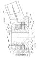
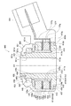
以下、本発明の実施の形態を、図面を参照しつつ説明する。図1に、本実施形態1に係るノッキングセンサ100を示す。また、図2に、このノッキングセンサ100のうち、樹脂被覆体150の回り込み部(基端側回り込み部)157付近を示す。なお、図1及び図2においては、図中、上側が軸線AX方向(後述する支持面111aに直交する直交方向)の先端側であり、図中、下側が軸線AX方向の基端側である。
このノッキングセンサ100は、支持部材110と、この支持部材110により支持される圧電素子135を含む圧電機構部130と、支持部材110及び圧電機構部130を覆う樹脂被覆体150とから構成されている。
(Embodiment 1)
Hereinafter, embodiments of the present invention will be described with reference to the drawings. FIG. 1 shows a knocking
The knocking
このうち支持部材110は、金属(具体的には、熱膨張係数が1×10⁻⁵/℃である炭素鋼)から一体的に形成されている。支持部材110は、軸線AXを有する円環状の支持本体部111と、この支持本体部111よりも外径が小さく、この支持本体部111から軸線AXに沿って先端側(図中、上方)に延びる円筒状の筒状部(挿通部)121とからなる。
支持本体部111は、径方向内側(後述する支持面111aに沿う沿面方向のうちの沿面方向内側)に位置する第1環状部113と、この第1環状部113の径方向外側(沿面方向外側)に位置し、軸線AX方向の長さが第1環状部113よりも小さく(約半分に)された第2環状部115とからなる。
Of these, the
The support
第1環状部113は、先端側を向く先端面113aと、基端側を向く基端面113bと、径方向内側(沿面方向内側)を向く内周面113cと、径方向外側(沿面方向外側)を向く外周面113dとを有する。また、第2環状部115は、先端側を向く先端面115aと、基端側を向く基端面115bと、径方向外側を向く外周面115dとを有する。
そして、第1環状部113の先端面113aと第2環状部115の先端面115aとが面一となって、支持本体部111の支持面111aを構成している。また、第1環状部113の基端面113bが、支持本体部111の座面(基端面)111bとなっている。この座面111bは、後述する樹脂被覆体150に覆われることなく露出している。また、第2環状部115の外周面115dが、支持本体部111の外周面(最外周面)111dとなっている。支持面111aは、後述する圧電素子135等を支持する面である。また、座面111bは、内燃機関のシリンダブロックに設けられたセンサ取付部(不図示)に当接される面である。
The first
The
支持本体部111のうち、第2環状部115の基端面115bには、先端側に向けて凹み基端側に開口する溝状で、支持本体部111の外周面111dに沿う環状に形成された第1係合環状溝部(第1係合部)119が設けられている。この第1係合環状溝部119の大きさは、内径φ20mm、外径φ22mm、幅1mm、深さ0.5mmである。この第1係合環状溝部119には、後述する第2係合環状突部159が入り込んで互いに密着しつつ係合している。
Of the support
支持本体部111の筒状部121は、自身の先端に位置して先端側を向く先端面121aと、径方向内側を向く内周面121cと、径方向外側を向く外周面121dとを有する。先端面121aは、後述する樹脂被覆体150に覆われることなく露出している。また、この筒状部121の外周面121dのうち、先端側の所定位置には、後述する樹脂被覆体150との密着性を高めるために、それぞれ環状をなす3本の環状溝部123,123,123が互いに平行に凹設されている。
The
次に、圧電機構部130について説明する。圧電機構部130は、基端側絶縁板131、基端側電極部材133、圧電素子135、先端側電極部材137、先端側絶縁板139及び錘部材141が、基端側から先端側にこの順に積層されることにより構成されている。
このうち基端側絶縁板131は、絶縁材料(具体的には、PBT)からなる円環板状をなし、支持部材110の筒状部121を内側に挿通しつつ、支持部材110の支持本体部111の支持面111a上に配置されている。この基端側絶縁板131は、支持部材110と次述する基端側電極部材133とを電気的に絶縁するものである。
Next, the
Of these, the base-
基端側電極部材133は、金属材料(具体的には、熱膨張係数が2×10⁻⁵/℃である黄銅)からなり、支持部材110の筒状部121を内側に挿通しつつ、基端側絶縁板131の先端側に配置されている。この基端側電極部材133は、円環板状の環状部133fと、この環状部133fから径方向外側に延出する端子部133gとからなる。環状部133fは、基端側絶縁板131と次述する圧電素子135との間に挟まれて、圧電素子135の基端面135bに当接している。一方、端子部133gは、環状部133fから後述するコネクタ部161まで所定位置で折り曲げられながら延出しており、圧電素子135の基端面135bから出力される電気信号の通電経路を構成している。
The proximal-
圧電素子135は、圧電効果を有する材料(具体的には、熱膨張係数が1×10⁻⁵/℃であるPZT)からなる円環状をなし、支持部材110の筒状部121を内側に挿通しつつ、基端側電極部材133の先端側に配置されている。この圧電素子135は、先端面135aと、その裏面をなす基端面135bと、これらの面を結ぶ内周面135c及び外周面135dを有する。
The
先端側電極部材137は、金属材料(具体的には、熱膨張係数が2×10⁻⁵/℃である黄銅)からなり、支持部材110の筒状部121を内側に挿通しつつ、圧電素子135の先端面135a上に配置されている。この基端側電極部材137は、円環板状の環状部137fと、この環状部137fから径方向外側に延出する端子部137gとからなる。環状部137fは、圧電素子135と次述する先端側絶縁板139との間に挟まれて、圧電素子135の先端面135aに当接している。一方、端子部137gは、環状部137fから後述するコネクタ部161まで所定の位置で折り曲げられながら延出しており、圧電素子135の先端面135aから出力される電気信号の通電経路を構成している。
The tip-
先端側絶縁板139は、絶縁材料(具体的には、PET)からなる円環板状をなし、支持部材110の筒状部121を内側に挿通しつつ、先端側電極部材137の先端側に配置されている。この先端側絶縁板139は、先端側電極部材137と次述する錘部材141とを電気的に絶縁するものである。
The distal-
錘部材141は、金属材料(具体的には、熱膨張係数が2×10⁻⁵/℃である真鍮)からなる円環状をなし、支持部材110の筒状部121を内側に挿通しつつ、先端側絶縁板139の先端側に配置されている。この錘部材141は、先端側絶縁板139を基端側に押圧し、圧電素子135に所定の荷重を付加した状態で、次述する接着材143により支持部材110の筒状部121に固定されている。
The
上述した圧電機構部130(基端側絶縁板131、基端側電極部材133、圧電素子135、先端側電極部材137、先端側絶縁板139及び錘部材141)の内周面130cと、支持部材110の筒状部121の外周面121dとの隙間には、接着材143が充填形成されている。この接着材143により、圧電機構部130を構成する基端側絶縁板131、基端側電極部材133、圧電素子135、先端側電極部材137、先端側絶縁板139及び錘部材141と、筒状部121の外周面121dとが、それぞれ互いに固定されている。
Inner
次に、樹脂被覆体150について説明する。この樹脂被覆体150は、絶縁性樹脂(具体的には、熱膨張係数が6×10⁻⁵/℃であるポリアミド樹脂)をモールド成形したものである。
この樹脂被覆体150は、概略円筒状をなす素子被覆部151と、この素子被覆部151から外側に延出し、外部機器(例えばエンジン制御装置など)の外部コネクタを接続するためのコネクタ部161とからなる。
このうち素子被覆部151は、支持部材110の先端側と基端側にそれぞれ密着して、素子被覆部151と支持部材110との間に圧電機構部130全体をシールしている。この素子被覆部151は、先端側に位置する先端側部153と、この先端側部153の基端側に連なる外側部155と、この外側部155に連なる回り込み部(基端側回り込み部)157とからなる。
Next, the
The
Among these, the
先端側部153は、先端側ほど径が小さくなるテーパ形状を有する環状をなす。この先端側部153は、圧電機構部130の先端面130a(錘部材141の先端面)に密着してこれを覆うと共に、支持部材110の筒状部121のうち外周面121dの先端側部分に密着してこれを覆っている。筒状部121の外周面121dの先端側部分には、前述のように、3本の環状溝部123,123,123が形成されているので、この部分で樹脂被覆体150(先端側部153)と支持部材110(筒状部121)との密着性が向上し、シール性が高くなっている。
The distal
外側部155は、径方向の厚みd1(具体的には1.5mm)が一定の円筒状をなす。この外側部155は、圧電機構部130の外周面130d、及び、支持部材110の支持本体部111の外周面111d(第2環状部115の外周面115d)に密着してこれらを覆っている。
The
回り込み部157は、外側部155に連なって径方向内側に延びると共に、支持本体部111の外周面111dに沿う環状に設けられている。この回り込み部157は、支持本体部111の基端側、より詳細には、第2環状部115の基端面115b側に回り込み、この基端面115bに密着してこれを覆っている。この回り込み部157のうち、第2環状部115の基端面115bに回り込んだ回り込み長さm1、詳細には、径方向に見たときの、外側部155の内周面155cから回り込み部157の内側端面157cまでの最短の回り込み長さm1は、1.5mmである。
The
また、回り込み部157には、先端側に向けて突出する突条状で、この回り込み部157の内側端面157cに沿う環状に形成された第2係合環状突部(第2係合部)159が設けられている。この第2係合環状突部159の大きさは、内径φ20mm、外径φ22mm、幅1mm、高さ0.5mmである。この第2係合環状突部159は、支持本体部111(第2環状部115)の基端側に設けられた第1係合環状溝部119に入り込んで互いに密着しつつ係合している。
Further, the
このノッキングセンサ100は、支持部材110の座面111bを、内燃機関のシリンダブロックの取付部に当接させて、図示しないボルトを支持部材110の内側に先端側から挿通して内燃機関に取り付けられる。
内燃機関でノッキングなどの異常振動が生じると、その異常振動が支持部材110の支持本体部111を介して圧電機構部130の圧電素子135に達する。そして、その異常振動に応じて圧電素子135から出力される電気信号が、基端側電極部材133及び先端側電極部材137から外部機器に対して出力される。
The knocking
When abnormal vibration such as knocking occurs in the internal combustion engine, the abnormal vibration reaches the
なお、このノッキングセンサ100では、樹脂被覆体150が支持本体部111の基端側に回り込む回り込み部157を有するにも拘わらず、支持本体部111の座面111bが、樹脂被覆体150(回り込み部157等)に覆われることなく露出している。このため、このノッキングセンサ100を内燃機関に取り付ける際に、支持本体部111の座面111bを、樹脂被覆体150を介在させることなく、エンジンブロックの取付部に直接当接させることができる。これにより、内燃機関で生じる振動がノッキングセンサに伝わりやすくなるので、ノッキングをより精度良く検知できる。
In this knocking
このノッキングセンサ100は、高温環境下に長期間晒されたり、冷熱サイクルの繰り返しを受けると、樹脂被覆体150を構成する樹脂材料に経年劣化が進行し、樹脂被覆体150に収縮(所謂、熱やせ)が生じる。特に、この経年劣化に伴う収縮は、主として外側部155の軸線AX方向に沿って大きく生じるので、樹脂被覆体150の外側部155が、支持本体部111の外周面111dの下側(基端側)から剥がれようとする。
When this knocking
これに対し、本実施形態1では、樹脂被覆体150に外側部155に連なる回り込み部157を設け、しかも、この回り込み部157の回り込み長さm1を、外側部155の厚みd1の0.3倍以上6倍以下(具体的には1倍)としている。このような回り込み部157が支持本体部111の基端側に位置することにより、外側部155の軸線AX方向の収縮が制限されるので、外側部155が軸線AX方向に大きく収縮して支持本体部111の外周面111dから剥がれることを防止できる。
On the other hand, in the first embodiment, a
更に、外側部155に連なる回り込み部157は、前述した第1係合環状溝部119と第2係合環状突部159とが互いに係合し、第2係合環状突部159が径方向に移動できなくなっている。このため、樹脂被覆体150が経年変化により収縮しても、支持本体部111に対する回り込み部157の径方向外側への相対的な移動を効果的に防止でき、この回り込み部157が移動して支持本体部111から剥がれることを効果的に防止できる。従って、これに連なる外側部155が軸線AX方向に大きく収縮して支持本体部111の外周面111dから剥がれることも効果的に防止できる。
Further, the
このように本実施形態1では、外側部155に連なる回り込み部157を支持本体部111の基端側に位置させてなることによる効果と、この回り込み部157に、支持本体部111の基端側の第1係合環状溝部119に係合する第2係合環状突部159を設けたことによる効果とが相俟って、樹脂被覆体150(特に外側部155)に経年変化に起因する収縮が生じたとしても、樹脂被覆体150が支持本体部111の外周面111dから剥がれることを効果的に防止できる。よって、支持部材110と樹脂被覆体150とのシールの耐久性を十分に向上させることができる。
As described above, in the first embodiment, the effect obtained by positioning the
また、本実施形態1では、支持部材110に環状に第1係合環状溝部119を設ける一方、樹脂被覆体150にこの第1係合環状溝部119内に入り込む環状の第2係合環状突部159を設けているので、全周にわたり第1係合環状溝部119と第2係合環状突部159とを互いに係合させることができる。しかも、溝部に突部を入り込ませて係合させているので、第1係合環状溝部119と第2係合環状突部159とを確実に係合させることができる。従って、回り込み部157が径方向外側に移動して支持本体部111から剥がれることを更に効果的に防止できるので、支持部材110と樹脂被覆体150とのシールの耐久性を更に向上させることができる。
In the first embodiment, the
次いで、このノッキングセンサ100の製造方法について説明する。
まず、支持部材110の筒状部121を内側に挿通させつつ、支持本体部111の支持面111a上に、基端側絶縁板131、基端側電極部材133、圧電素子135、先端側電極部材137、先端側絶縁板139及び錘部材141を、基端側から先端側にこの順に積層する。
Next, a method for manufacturing the knocking
First, while inserting the
次に、この圧電機構部130(基端側絶縁板131、基端側電極部材133、圧電素子135、先端側電極部材137、先端側絶縁板139及び錘部材141)の内周面130cと、筒状部121の外周面121dとの隙間に、接着材143を充填する。その際、錘部材141を基端側に押圧して、圧電素子135に所定の荷重を付加した状態で、圧電機構部130の各部材を筒状部121に接着固定する。
次に、この構成部品を射出成型用金型で取り囲み、この構成部品を覆うように絶縁製樹脂を射出成形して、樹脂被覆体150を形成する。かくして、ノッキングセンサ100が完成する。
Next, the inner
Next, this component is surrounded by an injection mold, and an insulating resin is injection-molded so as to cover the component, thereby forming the
(実施形態2)
次いで、第2の実施の形態について説明する。図3に、本実施形態2に係るノッキングセンサ200のうち、樹脂被覆体250の回り込み部(基端側回り込み部)257付近を示す。本実施形態2のノッキングセンサ200は、支持部材210の支持本体部211のうちの第2環状部215の形態が、上記実施形態1に係る支持部材110の支持本体部111のうちの第2環状部115の形態と異なる。また、樹脂被覆体250の回り込み部257の形態が、上記実施形態1に係る樹脂被覆体150の回り込み部157の形態と異なる。それ以外は、基本的に上記実施形態1と同様であるので、上記実施形態1と同様な部分の説明は、省略又は簡略化する。
(Embodiment 2)
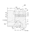
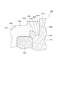
Next, a second embodiment will be described. FIG. 3 shows the vicinity of the wraparound portion (base end wraparound portion) 257 of the
本実施形態2に係るノッキングセンサ200は、支持部材210と、上記実施形態1と同様な圧電機構部130と、これらを覆う樹脂被覆体250とから構成されている。
このうち支持部材210は、環状の支持本体部211と、上記実施形態1と同様な筒状部121とからなる。支持本体部211は、上記実施形態1と同様な第1環状部113と、この第1環状部113の径方向外側に位置し、軸線AX方向の長さが第1環状部113よりも小さくされた第2環状部215とからなる。
The knocking
Among these members, the
この第2環状部215は、先端側を向く先端面215aと、基端側に形成された基端面215bと、径方向外側を向く外周面215dとを有する。そして、第1環状部113の先端面113aと第2環状部215の先端面215aとが面一となって、支持本体部211の支持面211aを構成している。また、第1環状部113の基端面113bが、支持本体部211の座面(基端面)211bとなっている。また、第2環状部215の外周面215dが、支持本体部211の外周面(最外周面)211dとなっている。
The second
支持本体部211のうち、第2環状部215の基端側には、径方向内側に向かうにつれて先端側に大きく凹み、支持本体部211の外周面211dに沿う環状に形成された第1係合テーパ状凹部(第1係合部)219が設けられている。この第1係合テーパ状凹部219には、後述する第2係合テーパ状凸部259が入り込んで互いに密着しつつ係合している。
A first engagement formed in an annular shape along the outer
また、樹脂被覆体250は、概略円筒状をなす素子被覆部251と、上記実施形態1と同様なコネクタ部161とからなる。素子被覆部251は、上記実施形態1と同様な先端側部153及び外側部155と、上記実施形態1とは形態の異なる回り込み部(基端側回り込み部)257とからなる。
In addition, the
この回り込み部257は、外側部155に連なって径方向内側に延びると共に、支持本体部211の外周面211dに沿う環状に設けられている。この回り込み部257は、支持本体部211の基端側、より詳細には、第2環状部215の基端面215b側に回り込んでいる。この回り込み部257のうち、第2環状部215の基端面215bに回り込んだ回り込み長さm2、詳細には、径方向に見たときの、外側部155の内周面155cから回り込み部257の内側端面257cまでの最短の回り込み長さm2は、0.6mmである。
The
また、この回り込み部257には、径方向内側に向かうにつれて先端側に向けて大きく突出し、回り込み部257の内側端面257cに沿う環状に形成された第2係合テーパ状凸部(第2係合部)259が設けられている。この第2係合テーパ状凸部259は、支持本体部211の基端側に設けられた第1係合テーパ状凹部219に入り込んで互いに密着しつつ係合している。
In addition, the
本実施形態2のノッキングセンサ200でも、高温環境下に長期間晒されたり、冷熱サイクルの繰り返し受けると、樹脂被覆体250を構成する樹脂材料に経年劣化が進行し、樹脂被覆体250に収縮が生じる。特に、この経年劣化に伴う収縮は、主として外側部155の軸線AX方向に沿って大きく生じるので、樹脂被覆体250の外側部155が、支持本体部211の外周面211dの基端側から剥がれようとする。
Even in the knocking
これに対し、本実施形態2でも、樹脂被覆体250に外側部155に連なる回り込み部257を設け、しかも、この回り込み部257の回り込み長さm2を、外側部155の厚みd1の0.3倍以上6倍以下(具体的には0.4倍)としている。このような回り込み部257が支持本体部211の基端側に位置することにより、外側部155の軸線AX方向の収縮が制限されるので、外側部155が軸線AX方向に大きく収縮して支持本体部211の外周面211dから剥がれることを防止できる。
On the other hand, also in the second embodiment, the
更に、外側部155に連なる回り込み部257は、前述した第1係合テーパ状凹部219と第2係合テーパ状凸部259とが互いに係合し、第2係合テーパ状凸部259が径方向に移動できなくなっている。このため、樹脂被覆体250が経年変化により収縮しても、支持本体部211に対する回り込み部257の径方向外側への相対的な移動を効果的に防止でき、この回り込み部257が移動して支持本体部211から剥がれることを効果的に防止できる。従って、これに連なる外側部155が軸線AX方向に大きく収縮して支持本体部211の外周面211dから剥がれることも効果的に防止できる。
Further, the
このように本実施形態2でも、外側部155に連なる回り込み部257を支持本体部211の基端側に位置させてなることによる効果と、この回り込み部257に、支持本体部211の基端側の第1係合テーパ状凹部219に係合する第2係合テーパ状凸部259を設けたことによる効果とが相俟って、樹脂被覆体250(特に外側部155)に経年変化に起因する収縮が生じたとしても、樹脂被覆体250が支持本体部211の外周面211dから剥がれることを効果的に防止できる。よって、支持部材210と樹脂被覆体250とのシールの耐久性を十分に向上させることができる。その他、上記実施形態1と同様な部分は、上記実施形態1と同様な作用効果を奏する。
As described above, also in the second embodiment, the
(実施形態3)
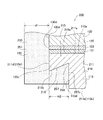
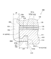
次いで、第3の実施の形態について説明する。図4に、本実施形態3に係るノッキングセンサ300を示す。また、図5に、このノッキングセンサ300のうち、樹脂被覆体350の回り込み部(基端側回り込み部)357付近を示す。本実施形態3のノッキングセンサ300は、支持部材310及び樹脂被覆体350の形態が、上記実施形態1,2に係る支持部材110,210及び樹脂被覆体150,250の形態と異なる。また、支持部材310及び圧電機構部130の径方向外側に外装部材343を有する点が、上記実施形態1,2と異なる。それ以外は、上記実施形態1又は2と同様であるので、上記実施形態1又は2と同様な部分の説明は、省略又は簡略化する。
(Embodiment 3)
Next, a third embodiment will be described. FIG. 4 shows a knocking
本実施形態3の支持部材310は、軸線AXを有する環状をなす支持本体部311のみからなる。つまり、この支持部材310は、上記実施形態1,2の支持部材110,210のうち筒状部(挿通部)121に相当する部分が存在しない形態を有する。そして、支持本体部311は、径方向内側に位置する第1環状部313と、この第1環状部313の径方向外側に位置し、軸線AX方向の長さが第1環状部313よりも小さくされた第2環状部315とからなる。
The
支持本体部311の第1環状部313は、先端側を向く先端面313aと、基端側を向く基端面313bと、径方向内側を向く内周面313cとを有する。また、第2環状部315は、先端側を向く先端面315aと、基端側を向く基端面315bと、径方向外側を向く外周面315dとを有する。そして、第1環状部313の先端面313aと第2環状部315の先端面315aとが面一となって、支持本体部311の支持面311aを構成している。また、第1環状部313の基端面313bが支持部材310の座面(基端面)311bとなっている。また、第2環状部315の外周面315dが、支持本体部311の外周面(最外周面)311dとなっている。
The first
支持部材311のうち、第2環状部315の基端面315bには、先端側に向けて凹み基端側に開口する溝状で、支持本体部311の外周面311dに沿う環状に形成された第1係合環状溝部(第1係合部)319が形成されている。この第1係合環状溝部319には、後述する第2係合環状突部359が入り込んで互いに密着しつつ係合している。
また、第2環状部315の外周面315dには、後述する外装部材343との密着性を高めるために、それぞれ環状をなす3本の環状溝部316,316,316が互いに平行に凹設されている。
Of the
In addition, on the outer
圧電機構部130は、上記実施形態1,2と同様である。即ち、圧電機構部130は、基端側絶縁板131、基端側電極部材133、圧電素子135、先端側電極部材137、先端側絶縁板139及び錘部材141が基端側から先端側に積層されて構成され、支持部材310の支持面311aに支持されている。
The
本実施形態3では、圧電機構部130は、圧電機構部130の径方向外側に形成された樹脂からなる外装部材343により、支持部材310に固定されている。具体的には、軸線AX方向に延びる筒状をなす外装部材343が、その先端側で圧電機構部130の外周面130dに接着すると共に、基端側で支持部材310の外周面311d(第2環状部315の外周面315d)に接着することにより、圧電機構部130を支持部材310に固定している。
In the third embodiment, the
次に、樹脂被覆体350は、素子被覆部351と、この素子被覆部351から外側に延出するコネクタ部361とからなる。
このうち素子被覆部351は、先端側に位置する先端側部353と、この先端側部353から基端側に連なり径方向内側に位置する内側部354と、先端側部353から基端側に連なり径方向外側に位置する外側部355と、この外側部355に連なる回り込み部(基端側回り込み部)357とからなる。
Next, the
Among these, the
先端側部353は、先端側ほど径が小さくなるテーパ形状を有する環状をなす。この先端側部353は、圧電機構部130の先端面130aに密着してこれを覆っている。
内側部354は、径方向の厚みが一定の円筒状をなす。この内側部354は、圧電機構部130の内周面130cに密着してこれを覆うと共に、支持部材310の支持面311aのうち径方向内側部分に密着してこれを覆っている。支持面311aの径方向内側部分には、基端側に向けて凹み先端側に開口する溝状で、環状に形成された環状溝部314が設けられている。従って、この部分で樹脂被覆体350(内側部354)と支持部材310との密着性が向上し、シール性が十分に高くなっている。
外側部355は、径方向の厚みd3(具体的には1.5mm)が一定の円筒状をなす。本実施形態3では、この外側部355は、主に外装部材343の外周面343dに密着し、この外装部材343を介して圧電機構部130の外周面130d及び支持本体部311の外周面311dを間接に覆っている。
The distal
The
The
回り込み部357は、外側部355に連なって径方向内側に延びると共に、支持本体部311の外周面311dに沿う環状に設けられている。この回り込み部357は、支持本体部311の基端側、より詳細には、第2環状部315の基端面315b側に回り込み、基端面315bに密着してこれを覆っている。この回り込み部357のうち、第2環状部315の基端面315bに回り込んだ回り込み長さm3、詳細には、径方向に見たときの、外側部355の内周面355cから回り込み部357の内側端面357cまでの最短の回り込み長さm3は、2.1mmである。
The
また、この回り込み部357には、先端側に向けて突出する突条状で、回り込み部357の内側端面357cに沿う環状に形成された第2係合環状突部(第2係合部)359が設けられている。この第2係合環状突部359は、第2環状部315に設けられた第1係合環状溝部319に入り込んで互いに密着しつつ係合している。
Further, the
本実施形態3のノッキングセンサ300でも、高温環境下に長期間晒されたり、冷熱サイクルの繰り返し受けると、樹脂被覆体350を構成する樹脂材料に経年劣化が進行し、樹脂被覆体350に収縮が生じる。特に、この経年劣化に伴う収縮は、主として外側部355の軸線AX方向に沿って大きく生じるので、樹脂被覆体350の外側部355が、外装部材343の外周面343dの基端側から剥がれようとする。
Even in the knocking
これに対し、本実施形態3でも、樹脂被覆体350に外側部355に連なる回り込み部357を設け、しかも、回り込み部357の回り込み長さm3を、外側部355の厚みd3の0.3倍以上6倍以下(具体的には1.4倍)としている。このような回り込み部357が支持本体部311の基端側に位置することにより、これに連なる外側部355の軸線AX方向の収縮が制限されるので、外側部355が軸線AX方向に大きく収縮して外装部材343の外周面343dから剥がれることを防止できる。
On the other hand, also in the third embodiment, the
更に、外側部355に連なる回り込み部357は、前述した第1係合環状溝部319と第2係合環状突部359とが互いに係合し、第2係合環状突部359が径方向に移動できなくなっている。このため、樹脂被覆体350が経年変化により収縮しても、支持本体部311に対する回り込み部357の径方向外側への相対的な移動を効果的に防止でき、この回り込み部357が支持本体部311から剥がれることを効果的に防止できる。
Furthermore, the
このように本実施形態3でも、外側部355に連なる回り込み部357を支持本体部311の基端側に位置させてなることによる効果と、この回り込み部357に、支持本体部311の基端側の第1係合環状溝部319に係合する第2係合環状突部359を設けたことによる効果とが相俟って、樹脂被覆体350(特に外側部355)に経年変化に起因する収縮が生じたとしても、樹脂被覆体350が支持本体部311から剥がれることを効果的に防止できる。よって、支持部材310と樹脂被覆体350とのシールの耐久性を十分に向上させることができる。その他、上記実施形態1又は2と同様な部分は、上記実施形態1又は2と同様な作用効果を奏する。
As described above, also in the third embodiment, the effect obtained by positioning the
次いで、このノッキングセンサ300の製造方法について説明する。
まず、支持部材310の支持面311a上に、圧電機構部130(基端側絶縁板131、基端側電極部材133、圧電素子135、先端側電極部材137、先端側絶縁板139及び錘部材141)を配置する。
その後、圧電機構部130の外周面130d、及び、支持本体部311の外周面311dに、樹脂を塗布し、これを硬化させて、外装部材343を形成する。その際、錘部材141を基端側に押圧して、圧電素子135に所定の荷重を付加した状態とする。
次に、この構成部品を射出成型用金型で取り囲み、この構成部品を覆うように絶縁製樹脂を射出成形して、樹脂被覆体350を形成する。かくして、ノッキングセンサ300が完成する。
Next, a method for manufacturing the knocking
First, on the
Thereafter, resin is applied to the outer
Next, the component is surrounded by an injection mold, and an insulating resin is injection-molded so as to cover the component, thereby forming a
(実施形態4)
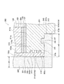
次いで、第4の実施の形態について説明する。図6に、本実施形態4に係るノッキングセンサ400を示す。また、図7に、このノッキングセンサ400のうち、樹脂被覆体450の先端側回り込み部458付近を示し、図8に、樹脂被覆体450の基端側回り込み部457付近を示す。なお、上記実施形態1〜3のいずれかと同様な部分の説明は、省略又は簡略化する。
(Embodiment 4)
Next, a fourth embodiment will be described. FIG. 6 shows a knocking
本実施形態4に係るノッキングセンサ400の支持部材410は、軸線AXを有する円環状の支持本体部411と、この支持本体部411から軸線AXに沿って先端側(図6中、上方)に延びる円筒状の筒状部(挿通部)421とからなる。
このうち支持本体部411は、径方向内側に位置する第1環状部413と、この第1環状部413の径方向外側に位置する第2環状部415とからなる。第1環状部413は、先端面413aと基端面413bと内周面413cと外周面413dとを有する。また、第2環状部415は、先端面415aと基端面415bと外周面415dとを有する。そして、第1環状部413の先端面413aと第2環状部415の先端面415aとが面一となって、支持本体部411の支持面411aを構成している。また、第1環状部413の基端面413bが、支持本体部411の座面(基端面)411bとなっている。この座面411bは、後述する樹脂被覆体450に覆われることなく露出している。また、第2環状部415の外周面415dが、支持本体部411の外周面(最外周面)411dとなっている。
A
Among these, the support
支持本体部411のうち、第2環状部415の基端面415bには、先端側に向けて凹み基端側に開口する溝状で、支持本体部411の外周面411dに沿う環状に形成された第1係合環状溝部(第1係合部)419が設けられている。この第1係合環状溝部419には、後述する第2係合環状突部459が入り込んで互いに密着しつつ係合している。
また、第1環状部413の先端面413aには、基端側に向けて凹み先端側に開口する溝状で、環状に形成された環状溝部414が設けられている。
Of the
In addition, an
支持本体部411の筒状部421は、自身の先端に位置して先端側を向く先端面421aと、径方向内側を向く内周面421cと、径方向外側を向く外周面421dとを有する。先端面421aは、後述する樹脂被覆体450に覆われることなく露出している。
また、この筒状部421の先端外側部分は、先端面421aよりも基端側に位置し先端面421aと平行な中間面421eを有する段付形状とされている。そして、この中間面421eには、基端側に向けて凹み先端側に開口する溝状で、筒状部421の外周面421dに沿う環状に形成された第3係合環状溝部(第3係合部)420が設けられている。この第3係合環状溝部420には、後述する第4係合環状突部460が入り込んで互いに密着しつつ係合している。
The
Further, the outer end portion of the
圧電機構部130は、上記実施形態1等と同様に、基端側絶縁板131、基端側電極部材133、圧電素子135、先端側電極部材137、先端側絶縁板139及び錘部材141が、基端側から先端側にこの順に積層されることにより構成されている。
この圧電機構部130の先端側には、皿バネ445を介して、支持部材410の筒状部421に螺合するナット447が配置されている。これにより、圧電機構部130が支持部材410の支持本体部411に向けて基端側に押圧され、支持本体部411との間に狭持されて、支持部材410に固定されている。
As in the first embodiment, the
A
次に、樹脂被覆体450について説明する。この樹脂被覆体450は、素子被覆部451とコネクタ部461とからなる。
このうち素子被覆部451は、支持部材410の先端側と基端側にそれぞれ密着して、素子被覆部451と支持部材410との間に圧電機構部130等をシールしている。この素子被覆部451は、先端側に位置し、先端側回り込み部458を含む先端側部453と、この先端側部453の基端側に連なる外側部455と、更にこの外側部455に連なる基端側回り込み部457と、圧電機構部130の径方向内側に配置された内側部454とからなる。
Next, the
Among these, the
先端側部453は、先端側ほど径が小さくなるテーパ形状を有する環状をなす。この先端側部453は、圧電機構部130の先端面130a(錘部材141の先端面)、皿バネ445及びナット447に密着してこれらを覆っている。また、先端側部453は、支持部材410の筒状部421の先端外側部分に密着してこれを覆っている。具体的には、先端部材453は、筒状部421のうち、外周面421dの先端側部分、中間面421e及び第3係合環状溝部420に密着している。
The distal
先端側部453は、径方向内側に向かって延びると共に、筒状部421の外周面421dに沿う環状に設けられた先端側回り込み部458を有する。この先端側回り込み部458は、筒状部421の先端側、より詳細には、中間面421eに回り込み、この中間面421eに密着してこれを覆っている。また、先端側回り込み部458には、先端側に向けて突出する突条状で、この先端側回り込み部458の内側端面458cに沿う環状に形成された第4係合環状突部(第4係合部)460が設けられている。この第4係合環状突部460は、筒状部421の先端側に設けられた第3係合環状溝部420に入り込んで互いに密着しつつ係合している。
The distal
外側部455は、径方向の厚みd4(具体的には1.5mm)が一定の円筒状をなす。この外側部455は、圧電機構部130の外周面130d、及び、支持部材410の支持本体部411の外周面411d(第2環状部415の外周面415d)に密着してこれらを覆っている。
The
基端側回り込み部457は、外側部455に連なって径方向内側に延びると共に、支持本体部411の外周面411dに沿う環状に設けられている。この基端側回り込み部457は、支持本体部411の基端側、より詳細には、第2環状部415の基端面415b側に回り込み、この基端面415bに密着してこれを覆っている。この基端側回り込み部457のうち、第2環状部415の基端面415bに回り込んだ回り込み長さm4、詳細には、径方向に見たときの、外側部455の内周面455cから回り込み部457の内側端面457cまでの最短の回り込み長さm4は、1.5mmである。
The proximal
また、基端側回り込み部457には、先端側に向けて突出する突条状で、この基端側回り込み部457の内側端面457cに沿う環状に形成された第2係合環状突部(第2係合部)459が設けられている。この第2係合環状突部459は、支持本体部411(第2環状部415)の基端側に設けられた第1係合環状溝部419に入り込んで互いに密着しつつ係合している。
Further, the proximal
内側部454は、径方向の厚みがほぼ一定の円筒状をなす。この内側部454は、主として、圧電機構部130の内周面130cと支持部材410の筒状部421の外周面421dとの隙間に充填形成され、これら内周面130c及び外周面421dにそれぞれ密着している。また、この内側部454は、支持本体部411の支持面411aに形成された環状溝部414にも入り込んでこれに密着している。
The
本実施形態4のノッキングセンサ400では、高温環境下に長期間晒されたり、冷熱サイクルの繰り返し受けると、樹脂被覆体450を構成する樹脂材料に経年劣化が進行し、樹脂被覆体450に収縮が生じる。特に、この経年劣化に伴う収縮は、主として外側部455の軸線AX方向に沿って大きく生じるので、樹脂被覆体450が、支持部材410の先端側及び基端側からそれぞれ剥がれようとする。
In the knocking
これに対し、本実施形態4では、樹脂被覆体450の先端側部453に先端側回り込み部458を設けている。この先端側回り込み部458が筒状部421の先端側に位置することにより、この先端側回り込み部458を含む先端側部453に連なる外側部455の軸線AX方向の収縮が制限されるので、外側部455が軸線AX方向に大きく収縮して、先端側部453が筒状部421の外周面421dから剥がれることを防止できる。
On the other hand, in the fourth embodiment, the front end
更に、この先端側回り込み部458は、その第4係合環状突部460が前述した第3係合環状溝部420と互いに係合し、第4係合環状突部460が径方向に移動できなくなっている。このため、樹脂被覆体450が経年変化により収縮しても、筒状部421に対する先端側回り込み部458の径方向外側への相対的な移動を効果的に防止でき、この先端側回り込み部458が筒状部421から剥がれることを効果的に防止できる。
Further, the distal end
このように、外側部455に連なる先端側部453の先端側回り込み部458を筒状部421の先端側に位置させてなることによる効果と、この先端側回り込み部458に、筒状部421の先端側の第3係合環状溝部420に係合する第4係合環状突部460を設けたことによる効果とが相俟って、樹脂被覆体450(特に外側部455)に経年変化に起因する収縮が生じたとしても、樹脂被覆体450が筒状部421から剥がれることを効果的に防止できる。
As described above, the effect of positioning the distal end
また、本実施形態4では、樹脂被覆体450に外側部455に連なる基端側回り込み部457を設け、しかも、この基端側回り込み部457の回り込み長さm4を、外側部455の厚みd4の0.3倍以上6倍以下(具体的には1倍)としている。このような基端側回り込み部457が支持本体部411の基端側に位置することにより、これに連なる外側部455の軸線AX方向の収縮が制限されるので、外側部455が軸線AX方向に大きく収縮して支持本体部411の外周面411dから剥がれることを防止できる。
In the fourth embodiment, the resin-coated
更に、この基端側回り込み部457は、その第2係合環状突部459が前述した第1係合環状溝部419と互いに係合し、第2係合環状突部459が径方向に移動できなくなっている。このため、樹脂被覆体450が経年変化により収縮しても、支持本体部411に対する基端側回り込み部457の径方向外側への相対的な移動を効果的に防止でき、この基端側回り込み部457が支持本体部411から剥がれることを効果的に防止できる。
Furthermore, the proximal end wrap-around
このように、外側部455に連なる基端側回り込み部457を支持本体部411の基端側に位置させてなることによる効果と、この基端側回り込み部457に、支持本体部411の基端側の第1係合環状溝部419に係合する第2係合環状突部459を設けたことによる効果とが相俟って、樹脂被覆体450(特に外側部455)に経年変化に起因する収縮が生じたとしても、樹脂被覆体450が支持本体部411から剥がれることを効果的に防止できる。
よって、本実施形態4のノッキングセンサ400では、支持部材410と樹脂被覆体450とのシールの耐久性を特に向上させることができる。
As described above, the proximal
Therefore, in the knocking
また、本実施形態4では、樹脂被覆体450が筒状部421の先端側に回り込む先端側回り込み部458を有するにも拘わらず、筒状部421の先端面421aが、樹脂被覆体450(先端側回り込み部458等)に覆われることなく露出している。このため、このノッキングセンサ400を内燃機関のエンジンブロックに取り付ける際に、取り付け用のボルトを、樹脂被覆体450を介在させることなく、筒状部421の先端面421aに直接当接させることができる。これにより、ノッキングセンサ400を内燃機関により確実に取り付けることができる。
In the fourth embodiment, the
また、本実施形態4では、樹脂被覆体450が支持本体部411の基端側に回り込む基端側回り込み部457を有するにも拘わらず、支持本体部411の座面411bが、樹脂被覆体450(基端側回り込み部457等)に覆われることなく露出している。このため、このノッキングセンサ400を内燃機関に取り付ける際に、支持本体部411の座面411bを、樹脂被覆体450を介在させることなく、エンジンブロックの取付部に直接当接させることができる。これにより、内燃機関で生じる振動がノッキングセンサ400に伝わりやすくなるので、ノッキングをより精度良く検知できる。
その他、上記実施形態1〜3のいずれかと同様な部分は、上記実施形態1〜3と同様な作用効果を奏する。
Further, in the fourth embodiment, the
In addition, the same part as any one of the first to third embodiments has the same effects as the first to third embodiments.
次いで、このノッキングセンサ400の製造方法について説明する。
まず、支持部材410の筒状部421を内側に挿通させつつ、支持部材410の支持面411a上に、圧電機構部130(基端側絶縁板131、基端側電極部材133、圧電素子135、先端側電極部材137、先端側絶縁板139及び錘部材141)を配置する。
その後、圧電機構部130上に皿バネ445を載置し、この上からナット447を締め付けて、圧電機構部130を支持部材410に固定する。
次に、この構成部品を射出成型用金型で取り囲み、この構成部品を覆うように絶縁製樹脂を射出成形して、樹脂被覆体450を形成する。かくして、ノッキングセンサ400が完成する。
Next, a method for manufacturing the knocking
First, while the
Thereafter, the
Next, this component is surrounded by an injection mold, and an insulating resin is injection-molded so as to cover the component, thereby forming a
以上において、本発明を実施形態に即して説明したが、本発明は上述の実施形態1〜4に限定されるものではなく、その要旨を逸脱しない範囲で、適宜変更して適用できることはいうまでもない。
例えば、上記実施形態1〜4では、回り込み部(基端側回り込み部)157,257,457を支持本体部111,211,311,411の外周面111d,211d,311d,411dに沿う環状に設けたが、回り込み部を、支持本体部111,211,311,411の外周面111d,211d,311d,411dに沿って断続的に複数並べて形成することもできる。
In the above, the present invention has been described with reference to the embodiments. However, the present invention is not limited to the above-described first to fourth embodiments, and can be appropriately modified and applied without departing from the gist thereof. Not too long.
For example, in the first to fourth embodiments, the wraparound portions (base end wraparound portions) 157, 257, and 457 are provided in an annular shape along the outer
また、上記実施形態1,2では、圧電機構部130を支持部材110,210に対して接着剤143を用いて固着したが、圧電機構部130の支持部材110,210に対する固着手段はこれに限定されない。例えば、実施形態4で説明したように、支持部材110,210の筒状部121の外周面121dにネジ部を形成し、このネジ部に螺合するナット部材を用いて、圧電機構部130を支持部材110,210の支持本体部111,211に向けて基端側に押圧し、圧電機構部130を支持本体部111,211との間で狭持することにより、圧電機構部130を支持部材110,210に対して固着してもよい。
In the first and second embodiments, the
100,200,300,400 ノッキングセンサ
110,210,310,410 支持部材
111,211,311,411 支持本体部
111a,211a,311a,411a 支持面
111b,211b,311b,411b 座面(基端面)
111d,211d,311d,411d 外周面(外周)
119,319,419 第1係合環状溝部(第1係合部)
219 第1係合テーパ状凹部(第1係合部)
121,421 筒状部(挿通部)
121a,421a 先端面
121d,421d 外周面(外周)
420 第3係合環状溝部(第3係合部)
130 圧電機構部
130d 外周面(外周)
135 圧電素子
135d 外周面(外周)
150,250,350,450 樹脂被覆体
151,251,351,451 素子被覆部
153,353,453 先端側部
354,454 内側部
155,355,455 外側部
157,257,357,457 回り込み部(基端側回り込み部)
159,359,459 第2係合環状突部(第2係合部)
259 第2係合テーパ状凸部(第2係合部)
458 先端側回り込み部
460 第4係合環状突部(第4係合部)
161,361,461 コネクタ部
AX 軸線
d1,d3,d4 厚み
m1,m2,m3,m4 回り込み長さ
100, 200, 300, 400 Knocking
111d, 211d, 311d, 411d Outer peripheral surface (outer periphery)
119, 319, 419 First engagement annular groove (first engagement portion)
219 First engagement tapered recess (first engagement portion)
121,421 cylindrical part (insertion part)
121a, 421a
420 3rd engagement annular groove (3rd engagement part)
130
135
150, 250, 350, 450 Resin covering 151, 251, 351, 451
159, 359, 459 Second engagement annular protrusion (second engagement portion)
259 Second engagement taper convex portion (second engagement portion)
458 Tip-
161,361,461 Connector part AX Axis d1, d3, d4 Thickness m1, m2, m3, m4 Wrapping length
Claims (13)
前記圧電素子を直接又は間接に支持する支持面を含む支持本体部を有する支持部材と、
前記支持面に直交する直交方向のうち、前記支持面が向く側を先端側、これとは反対側を基端側とし、
前記支持面に沿う沿面方向のうち、前記圧電素子及び前記支持本体部の外側を向く側を沿面方向外側、前記圧電素子及び前記支持本体部の内側を向く側を沿面方向内側としたとき、
前記圧電素子、及び、前記支持部材の少なくとも一部を覆う樹脂被覆体であって、前記圧電素子の外周及び前記支持本体部の外周を覆う外側部を有する樹脂被覆体と、を備える
ノッキングセンサであって、
前記支持部材の前記支持本体部は、
自身の前記基端側に第1係合部を有し、
前記樹脂被覆体は、
前記外側部に連なって前記沿面方向内側に延びて、前記支持本体部の前記基端側に回り込む回り込み部であって、前記第1係合部と互いに係合する第2係合部を含む回り込み部を有する
ノッキングセンサ。 A piezoelectric element;
A support member having a support body portion including a support surface that directly or indirectly supports the piezoelectric element;
Of the orthogonal directions orthogonal to the support surface, the side facing the support surface is the distal end side, and the opposite side is the base end side,
Of the creeping directions along the support surface, the side facing the outside of the piezoelectric element and the support body part is the creeping direction outside, and the side facing the inside of the piezoelectric element and the support body part is the creeping direction inside,
A knocking sensor comprising: a resin cover that covers at least a part of the piezoelectric element and the support member, and a resin cover having an outer portion that covers an outer periphery of the piezoelectric element and an outer periphery of the support main body. There,
The support body portion of the support member is
Having a first engagement portion on its proximal side,
The resin coating is
A wraparound portion that is connected to the outer portion and extends inward in the creeping direction, and wraps around the base end side of the support main body, and includes a second engagement portion that engages with the first engagement portion. Knock sensor having a portion.
前記回り込み部を、前記支持本体部の外周に沿う環状に設けてなる
ノッキングセンサ。 The knocking sensor according to claim 1,
A knocking sensor in which the wraparound portion is provided in an annular shape along the outer periphery of the support main body portion.
前記沿面方向に見て、前記回り込み部のうち、前記外側部の内周から前記回り込み部の内側端までの最短の回り込み長さを、前記外側部の厚みの、0.3倍以上6倍以下としてなる
ノッキングセンサ。 The knocking sensor according to claim 2, wherein
The shortest wraparound length from the inner periphery of the outer portion to the inner end of the wrap portion is 0.3 to 6 times the thickness of the outer portion when viewed in the creeping direction. As a knocking sensor.
前記第1係合部は、
前記先端側に向けて凹み前記基端側に開口する溝状で、前記支持本体部の外周に沿う環状に形成されてなる第1係合環状溝部であり、
前記第2係合部は、
前記先端側に向けて突出する環形突条状で、前記第1係合環状溝部内に入り込んでなる第2係合環状突部である
ノッキングセンサ。 The knocking sensor according to claim 2 or 3, wherein
The first engaging portion is
It is a first engagement annular groove formed in an annular shape along the outer periphery of the support main body in a groove shape that is recessed toward the distal end side and opens to the proximal end side.
The second engaging portion is
A knocking sensor, which is a second engaging annular protrusion that enters the first engaging annular groove with an annular protrusion protruding toward the distal end.
前記支持本体部は、
自身の基端に位置して前記基端側を向く基端面であって、前記樹脂被覆体に覆われることなく露出してなる基端面を有する
ノッキングセンサ。 The knocking sensor according to any one of claims 1 to 4,
The support main body is
A knocking sensor having a base end surface that is located at the base end of the base and faces the base end side and is exposed without being covered with the resin coating.
前記圧電素子を直接又は間接に支持する支持面を含む支持本体部、及び、この支持本体部から延びて前記圧電素子内に挿通される挿通部を有する支持部材と、
前記支持面に直交する直交方向のうち、前記支持面が向く側を先端側、これとは反対側を基端側とし、
前記支持面に沿う沿面方向のうち、前記圧電素子及び前記支持本体部の外側を向く側を沿面方向外側、前記圧電素子及び前記支持本体部の内側を向く側を沿面方向内側としたとき、
前記圧電素子、及び、前記支持部材の少なくとも一部を覆う樹脂被覆体であって、前記圧電素子の外周及び前記支持本体部の外周を覆う外側部、並びに、この外側部の前記先端側に連なり前記挿通部の外周先端側を覆う先端側部を有する樹脂被覆体と、を備える
ノッキングセンサであって、
前記支持部材及び前記樹脂被覆体は、
前記支持本体部の前記基端側に設けられた第1係合部と、前記外側部に連なって前記沿面方向内側に延びて、前記支持本体部の前記基端側に回り込む基端側回り込み部であって、前記第1係合部と互いに係合する第2係合部を含む基端側回り込み部との組み合わせ、及び、
前記挿通部の前記先端側に設けられた第3係合部と、前記先端側部に含まれ、前記沿面方向内側に延びて、前記挿通部の前記先端側に回り込む先端側回り込み部であって、前記第3係合部と互いに係合する第4係合部を含む先端側回り込み部との組み合わせ、の少なくともいずれかを有する
ノッキングセンサ。 An annular piezoelectric element;
A support main body including a support surface that directly or indirectly supports the piezoelectric element, and a support member having an insertion portion that extends from the support main body and is inserted into the piezoelectric element;
Of the orthogonal directions orthogonal to the support surface, the side facing the support surface is the distal end side, and the opposite side is the base end side,
Of the creeping directions along the support surface, the side facing the outside of the piezoelectric element and the support body part is the creeping direction outside, and the side facing the inside of the piezoelectric element and the support body part is the creeping direction inside,
A resin coating covering at least a part of the piezoelectric element and the support member, the outer part covering the outer periphery of the piezoelectric element and the outer periphery of the support main body, and the leading end side of the outer part. A knocking sensor comprising: a resin cover having a distal end side portion covering an outer peripheral distal end side of the insertion portion;
The support member and the resin coating are
A first engagement portion provided on the base end side of the support main body portion, and a base end side wrap portion that extends inward of the creeping direction and extends to the base end side of the support main body portion. A combination of the first engagement portion and the proximal wraparound portion including the second engagement portion engaging with each other; and
A third engagement portion provided on the distal end side of the insertion portion; and a distal end wrap portion included in the distal end side portion, extending inward in the creeping direction and wrapping around the distal end side of the insertion portion. A knocking sensor having at least one of a combination of the third engagement portion and a distal end side wraparound portion including a fourth engagement portion that engages with each other.
前記支持部材及び前記樹脂被覆体は、
前記第1係合部と前記基端側回り込み部との組み合わせを有し、
前記基端側回り込み部を、前記支持本体部の外周に沿う環状に設けてなる
ノッキングセンサ。 The knocking sensor according to claim 6, wherein
The support member and the resin coating are
A combination of the first engagement portion and the proximal end wrap portion;
A knocking sensor in which the proximal end wraparound portion is provided in an annular shape along the outer periphery of the support main body portion.
前記沿面方向に見て、前記基端側回り込み部のうち、前記外側部の内周から前記基端側回り込み部の内側端までの最短の回り込み長さを、前記外側部の厚みの、0.3倍以上6倍以下としてなる
ノッキングセンサ。 The knocking sensor according to claim 7,
In the creeping direction, the shortest wraparound length from the inner periphery of the outer side portion to the inner end of the base end side wrap portion of the proximal end side wrap portion is set to 0. 0 of the thickness of the outer portion. Knocking sensor that is 3 times or more and 6 times or less.
前記第1係合部は、
前記先端側に向けて凹み前記基端側に開口する溝状で、前記支持本体部の外周に沿う環状に形成されてなる第1係合環状溝部であり、
前記第2係合部は、
前記先端側に向けて突出する環形突条状で、前記第1係合環状溝部内に入り込んでなる第2係合環状突部である
ノッキングセンサ。 The knocking sensor according to claim 7 or 8,
The first engaging portion is
It is a first engagement annular groove formed in an annular shape along the outer periphery of the support main body in a groove shape that is recessed toward the distal end side and opens to the proximal end side.
The second engaging portion is
A knocking sensor, which is a second engaging annular protrusion that enters the first engaging annular groove with an annular protrusion protruding toward the distal end.
前記支持本体部は、
自身の基端に位置して前記基端側を向く基端面であって、前記樹脂被覆体に覆われることなく露出してなる基端面を有する
ノッキングセンサ。 The knocking sensor according to any one of claims 7 to 9,
The support main body is
A knocking sensor having a base end surface that is located at the base end of the base and faces the base end side and is exposed without being covered with the resin coating.
前記支持部材及び前記樹脂被覆体は、
前記第3係合部と前記先端側回り込み部との組み合わせを有し、
前記先端側回り込み部を、前記挿通部の外周に沿う環状に設けてなる
ノッキングセンサ。 The knocking sensor according to any one of claims 6 to 10,
The support member and the resin coating are
It has a combination of the third engagement part and the tip side wraparound part,
A knocking sensor in which the tip side wraparound portion is provided in an annular shape along the outer periphery of the insertion portion.
前記第3係合部は、
前記基端側に向けて凹み前記先端側に開口する溝状で、前記挿通部の外周に沿う環状に形成されてなる第3係合環状溝部であり、
前記第4係合部は、
前記基端側に向けて突出する環形突条状で、前記第3係合環状溝部内に入り込んでなる第4係合環状突部である
ノッキングセンサ。 The knocking sensor according to claim 11, wherein
The third engaging portion is
A groove shape that is recessed toward the base end side and opens to the tip end side, and is a third engagement annular groove portion formed in an annular shape along the outer periphery of the insertion portion;
The fourth engaging portion is
A knocking sensor, which is a fourth engagement annular protrusion, which is an annular protrusion protruding toward the base end side and enters into the third engagement annular groove.
前記挿通部は、
自身の先端に位置して前記先端側を向く先端面であって、前記樹脂被覆体に覆われることなく露出してなる先端面を有する
ノッキングセンサ。 The knocking sensor according to claim 11 or 12,
The insertion part is
A knocking sensor having a tip surface located at the tip of itself and facing the tip side, the tip surface being exposed without being covered with the resin coating.
Priority Applications (4)
| Application Number | Priority Date | Filing Date | Title |
|---|---|---|---|
| JP2009052337A JP5027834B2 (en) | 2008-07-14 | 2009-03-05 | Knocking sensor |
| DE102009032977.3A DE102009032977B4 (en) | 2008-07-14 | 2009-07-14 | knock sensor |
| US12/502,505 US8266948B2 (en) | 2008-07-14 | 2009-07-14 | Knocking sensor |
| CN2009101585577A CN101629863B (en) | 2008-07-14 | 2009-07-14 | Knocking sensor |
Applications Claiming Priority (3)
| Application Number | Priority Date | Filing Date | Title |
|---|---|---|---|
| JP2008183030 | 2008-07-14 | ||
| JP2008183030 | 2008-07-14 | ||
| JP2009052337A JP5027834B2 (en) | 2008-07-14 | 2009-03-05 | Knocking sensor |
Publications (2)
| Publication Number | Publication Date |
|---|---|
| JP2010044047A true JP2010044047A (en) | 2010-02-25 |
| JP5027834B2 JP5027834B2 (en) | 2012-09-19 |
Family
ID=41427496
Family Applications (1)
| Application Number | Title | Priority Date | Filing Date |
|---|---|---|---|
| JP2009052337A Active JP5027834B2 (en) | 2008-07-14 | 2009-03-05 | Knocking sensor |
Country Status (4)
| Country | Link |
|---|---|
| US (1) | US8266948B2 (en) |
| JP (1) | JP5027834B2 (en) |
| CN (1) | CN101629863B (en) |
| DE (1) | DE102009032977B4 (en) |
Cited By (1)
| Publication number | Priority date | Publication date | Assignee | Title |
|---|---|---|---|---|
| CN108955861A (en) * | 2017-05-19 | 2018-12-07 | 大陆汽车电子(长春)有限公司 | Detonation sensor and detonation sensor component |
Families Citing this family (7)
| Publication number | Priority date | Publication date | Assignee | Title |
|---|---|---|---|---|
| US8286469B2 (en) * | 2007-03-19 | 2012-10-16 | Conti Temic Microelectronic Gmbh | Insert molded electrical contact |
| CN102539066A (en) * | 2010-12-10 | 2012-07-04 | 比亚迪股份有限公司 | Preparation method for knock sensor |
| JP5314073B2 (en) * | 2011-04-08 | 2013-10-16 | 三菱電機株式会社 | Knock sensor for internal combustion engine |
| DE102015201402A1 (en) * | 2015-01-28 | 2016-07-28 | Robert Bosch Gmbh | Vibration sensor for absorbing vibrations of a vibration causing component |
| FR3059774B1 (en) * | 2016-12-01 | 2019-05-10 | Continental Automotive France | CLAMP SENSOR WITH LOWER FLANGE WITH HOLE HOLES |
| FR3108178B1 (en) * | 2020-03-11 | 2024-03-15 | Vitesco Technologies | DEVICE FOR MANAGING VIBRATIONS OF A MOTOR VEHICLE AND ASSOCIATED METHOD |
| JP7480682B2 (en) | 2020-11-17 | 2024-05-10 | トヨタ紡織株式会社 | Internal combustion engine cover |
Citations (4)
| Publication number | Priority date | Publication date | Assignee | Title |
|---|---|---|---|---|
| JPH11264759A (en) * | 1998-03-19 | 1999-09-28 | Denso Corp | Knocking detection device |
| JP2001004476A (en) * | 1999-06-25 | 2001-01-12 | Ngk Spark Plug Co Ltd | Nonresonant knock sensor |
| JP2003517593A (en) * | 1999-12-15 | 2003-05-27 | ローベルト ボツシユ ゲゼルシヤフト ミツト ベシユレンクテル ハフツング | Vibration pickup with pressure sleeve |
| JP2004257834A (en) * | 2003-02-25 | 2004-09-16 | Denso Corp | Knock sensor |
Family Cites Families (13)
| Publication number | Priority date | Publication date | Assignee | Title |
|---|---|---|---|---|
| JPH0512740Y2 (en) * | 1988-01-11 | 1993-04-02 | ||
| FR2703772B1 (en) * | 1993-04-10 | 1995-05-19 | Bosch Gmbh Robert | Pressure socket, in particular for a knock sensor. |
| DE19612541A1 (en) * | 1996-03-29 | 1997-10-02 | Bosch Gmbh Robert | Vibration pick-up with pressure sleeve in housing e.g. for engine knock sensor |
| DE19829379C2 (en) * | 1998-07-01 | 2002-11-07 | Bosch Gmbh Robert | Vibration sensor with a pressure sleeve |
| DE19829409C2 (en) * | 1998-07-01 | 2003-11-13 | Bosch Gmbh Robert | Vibration sensor with a pressure sleeve |
| DE19829407A1 (en) * | 1998-07-01 | 2000-01-13 | Bosch Gmbh Robert | Oscillation detector with pressure sleeve e.g. knock sensor for car IC engine |
| JP2003194652A (en) * | 2001-12-28 | 2003-07-09 | Ngk Spark Plug Co Ltd | Nonresonant knocking sensor |
| US6752005B2 (en) * | 2002-04-26 | 2004-06-22 | Ngk Spark Plug Co., Ltd. | Nonresonant type knock sensor |
| JP2005227265A (en) * | 2004-01-15 | 2005-08-25 | Ngk Spark Plug Co Ltd | Knocking sensor |
| JP4053514B2 (en) * | 2004-05-26 | 2008-02-27 | 三菱電機株式会社 | Internal combustion engine knocking sensor and manufacturing method thereof |
| JP2006267083A (en) * | 2005-02-25 | 2006-10-05 | Ngk Spark Plug Co Ltd | Knocking sensor |
| JP4332564B2 (en) | 2007-01-26 | 2009-09-16 | 株式会社オリンピア | Directional device for a ball game machine |
| JP5029225B2 (en) | 2007-08-28 | 2012-09-19 | Toto株式会社 | Faucet device |
-
2009
- 2009-03-05 JP JP2009052337A patent/JP5027834B2/en active Active
- 2009-07-14 CN CN2009101585577A patent/CN101629863B/en active Active
- 2009-07-14 DE DE102009032977.3A patent/DE102009032977B4/en active Active
- 2009-07-14 US US12/502,505 patent/US8266948B2/en active Active
Patent Citations (4)
| Publication number | Priority date | Publication date | Assignee | Title |
|---|---|---|---|---|
| JPH11264759A (en) * | 1998-03-19 | 1999-09-28 | Denso Corp | Knocking detection device |
| JP2001004476A (en) * | 1999-06-25 | 2001-01-12 | Ngk Spark Plug Co Ltd | Nonresonant knock sensor |
| JP2003517593A (en) * | 1999-12-15 | 2003-05-27 | ローベルト ボツシユ ゲゼルシヤフト ミツト ベシユレンクテル ハフツング | Vibration pickup with pressure sleeve |
| JP2004257834A (en) * | 2003-02-25 | 2004-09-16 | Denso Corp | Knock sensor |
Cited By (1)
| Publication number | Priority date | Publication date | Assignee | Title |
|---|---|---|---|---|
| CN108955861A (en) * | 2017-05-19 | 2018-12-07 | 大陆汽车电子(长春)有限公司 | Detonation sensor and detonation sensor component |
Also Published As
| Publication number | Publication date |
|---|---|
| DE102009032977B4 (en) | 2014-07-03 |
| JP5027834B2 (en) | 2012-09-19 |
| US20100005859A1 (en) | 2010-01-14 |
| CN101629863B (en) | 2012-08-08 |
| CN101629863A (en) | 2010-01-20 |
| US8266948B2 (en) | 2012-09-18 |
| DE102009032977A1 (en) | 2010-01-21 |
Similar Documents
| Publication | Publication Date | Title |
|---|---|---|
| JP5027834B2 (en) | Knocking sensor | |
| JP3942176B2 (en) | Glow plug with combustion pressure detection function and manufacturing method thereof | |
| US6781289B2 (en) | Piezo actuator | |
| JP4209407B2 (en) | Ignition device for internal combustion engine | |
| US7905209B2 (en) | Glow plug with combustion pressure sensor | |
| JP5339898B2 (en) | Glow plug with integrated pressure sensor and glow plug body | |
| JP2004278934A (en) | Glow plug with combustion pressure detection function | |
| JP2010271321A (en) | Device for detecting combustion chamber pressure of internal combustion engine | |
| JP2011169887A (en) | Combustion pressure sensor | |
| JP3900060B2 (en) | Glow plug with combustion pressure sensor | |
| US20120234084A1 (en) | Device for detecting a combustion chamber pressure of an internal combustion engine | |
| KR100759163B1 (en) | Stick-shaped ignition coil having internal connecting structure | |
| US20110192358A1 (en) | Device including a pressure sensor for measuring pressures in an internal combustion engine, and body for such a device | |
| JP6181663B2 (en) | Knocking sensor | |
| JP4691006B2 (en) | Knocking sensor | |
| JP2004163091A (en) | Glow plug with combustion pressure sensor | |
| JP2019215345A (en) | Diaphragm pressure sensor comprising measuring spring support pipe and pressure sensor coated on the measuring spring support pipe | |
| JP5165062B2 (en) | Piezoelectric module, internal combustion engine and glow plug | |
| JP2006267083A (en) | Knocking sensor | |
| JP4800539B2 (en) | Vibration detector with pressure sleeve | |
| JP2001264155A (en) | Vibration detector equipped with pressure sleeve and method for manufacture of vibration detector | |
| JP7027251B2 (en) | Knocking sensor | |
| CN111896171A (en) | Knock sensor | |
| JP2010242576A (en) | Fuel injector and internal electric connecting method of the same | |
| JP2020180938A (en) | Knock sensor |
Legal Events
| Date | Code | Title | Description |
|---|---|---|---|
| A621 | Written request for application examination |
Free format text: JAPANESE INTERMEDIATE CODE: A621 Effective date: 20101210 |
|
| A977 | Report on retrieval |
Free format text: JAPANESE INTERMEDIATE CODE: A971007 Effective date: 20120518 |
|
| TRDD | Decision of grant or rejection written | ||
| A01 | Written decision to grant a patent or to grant a registration (utility model) |
Free format text: JAPANESE INTERMEDIATE CODE: A01 Effective date: 20120529 |
|
| A01 | Written decision to grant a patent or to grant a registration (utility model) |
Free format text: JAPANESE INTERMEDIATE CODE: A01 |
|
| A61 | First payment of annual fees (during grant procedure) |
Free format text: JAPANESE INTERMEDIATE CODE: A61 Effective date: 20120622 |
|
| FPAY | Renewal fee payment (event date is renewal date of database) |
Free format text: PAYMENT UNTIL: 20150629 Year of fee payment: 3 |
|
| R150 | Certificate of patent or registration of utility model |
Ref document number: 5027834 Country of ref document: JP Free format text: JAPANESE INTERMEDIATE CODE: R150 Free format text: JAPANESE INTERMEDIATE CODE: R150 |
|
| R250 | Receipt of annual fees |
Free format text: JAPANESE INTERMEDIATE CODE: R250 |
|
| R250 | Receipt of annual fees |
Free format text: JAPANESE INTERMEDIATE CODE: R250 |
|
| R250 | Receipt of annual fees |
Free format text: JAPANESE INTERMEDIATE CODE: R250 |
|
| R250 | Receipt of annual fees |
Free format text: JAPANESE INTERMEDIATE CODE: R250 |
|
| R250 | Receipt of annual fees |
Free format text: JAPANESE INTERMEDIATE CODE: R250 |
|
| R250 | Receipt of annual fees |
Free format text: JAPANESE INTERMEDIATE CODE: R250 |
|
| R250 | Receipt of annual fees |
Free format text: JAPANESE INTERMEDIATE CODE: R250 |
|
| R250 | Receipt of annual fees |
Free format text: JAPANESE INTERMEDIATE CODE: R250 |
|
| S531 | Written request for registration of change of domicile |
Free format text: JAPANESE INTERMEDIATE CODE: R313531 |
|
| R350 | Written notification of registration of transfer |
Free format text: JAPANESE INTERMEDIATE CODE: R350 |
|
| R250 | Receipt of annual fees |
Free format text: JAPANESE INTERMEDIATE CODE: R250 |