JP2010043524A - Handle assembly with controlled light distribution - Google Patents
Handle assembly with controlled light distribution Download PDFInfo
- Publication number
- JP2010043524A JP2010043524A JP2009169989A JP2009169989A JP2010043524A JP 2010043524 A JP2010043524 A JP 2010043524A JP 2009169989 A JP2009169989 A JP 2009169989A JP 2009169989 A JP2009169989 A JP 2009169989A JP 2010043524 A JP2010043524 A JP 2010043524A
- Authority
- JP
- Japan
- Prior art keywords
- leg
- bezel
- light
- light pipe
- handle
- Prior art date
- Legal status (The legal status is an assumption and is not a legal conclusion. Google has not performed a legal analysis and makes no representation as to the accuracy of the status listed.)
- Granted
Links
Images


Classifications
-
- G—PHYSICS
- G02—OPTICS
- G02B—OPTICAL ELEMENTS, SYSTEMS OR APPARATUS
- G02B6/00—Light guides; Structural details of arrangements comprising light guides and other optical elements, e.g. couplings
- G02B6/0001—Light guides; Structural details of arrangements comprising light guides and other optical elements, e.g. couplings specially adapted for lighting devices or systems
- G02B6/0011—Light guides; Structural details of arrangements comprising light guides and other optical elements, e.g. couplings specially adapted for lighting devices or systems the light guides being planar or of plate-like form
- G02B6/0013—Means for improving the coupling-in of light from the light source into the light guide
- G02B6/0015—Means for improving the coupling-in of light from the light source into the light guide provided on the surface of the light guide or in the bulk of it
- G02B6/0018—Redirecting means on the surface of the light guide
-
- B—PERFORMING OPERATIONS; TRANSPORTING
- B60—VEHICLES IN GENERAL
- B60Q—ARRANGEMENT OF SIGNALLING OR LIGHTING DEVICES, THE MOUNTING OR SUPPORTING THEREOF OR CIRCUITS THEREFOR, FOR VEHICLES IN GENERAL
- B60Q3/00—Arrangement of lighting devices for vehicle interiors; Lighting devices specially adapted for vehicle interiors
- B60Q3/20—Arrangement of lighting devices for vehicle interiors; Lighting devices specially adapted for vehicle interiors for lighting specific fittings of passenger or driving compartments; mounted on specific fittings of passenger or driving compartments
- B60Q3/267—Door handles; Hand grips
-
- B—PERFORMING OPERATIONS; TRANSPORTING
- B60—VEHICLES IN GENERAL
- B60Q—ARRANGEMENT OF SIGNALLING OR LIGHTING DEVICES, THE MOUNTING OR SUPPORTING THEREOF OR CIRCUITS THEREFOR, FOR VEHICLES IN GENERAL
- B60Q3/00—Arrangement of lighting devices for vehicle interiors; Lighting devices specially adapted for vehicle interiors
- B60Q3/60—Arrangement of lighting devices for vehicle interiors; Lighting devices specially adapted for vehicle interiors characterised by optical aspects
- B60Q3/62—Arrangement of lighting devices for vehicle interiors; Lighting devices specially adapted for vehicle interiors characterised by optical aspects using light guides
- B60Q3/64—Arrangement of lighting devices for vehicle interiors; Lighting devices specially adapted for vehicle interiors characterised by optical aspects using light guides for a single lighting device
-
- E—FIXED CONSTRUCTIONS
- E05—LOCKS; KEYS; WINDOW OR DOOR FITTINGS; SAFES
- E05B—LOCKS; ACCESSORIES THEREFOR; HANDCUFFS
- E05B17/00—Accessories in connection with locks
- E05B17/10—Illuminating devices on or for locks or keys; Transparent or translucent lock parts; Indicator lights
-
- E—FIXED CONSTRUCTIONS
- E05—LOCKS; KEYS; WINDOW OR DOOR FITTINGS; SAFES
- E05B—LOCKS; ACCESSORIES THEREFOR; HANDCUFFS
- E05B85/00—Details of vehicle locks not provided for in groups E05B77/00 - E05B83/00
- E05B85/10—Handles
- E05B85/12—Inner door handles
-
- E—FIXED CONSTRUCTIONS
- E05—LOCKS; KEYS; WINDOW OR DOOR FITTINGS; SAFES
- E05B—LOCKS; ACCESSORIES THEREFOR; HANDCUFFS
- E05B85/00—Details of vehicle locks not provided for in groups E05B77/00 - E05B83/00
- E05B85/10—Handles
- E05B85/14—Handles pivoted about an axis parallel to the wing
Abstract
Description
本明細書の主題は、一般に照光式ハンドル組立体に関し、より詳細にはハンドル組立体の対象領域へ光を誘導する光パイプを有するハンドル組立体に関する。 The subject matter herein relates generally to an illuminated handle assembly, and more particularly to a handle assembly having a light pipe that directs light to a target area of the handle assembly.
自動車内部などで使用されるハンドル組立体は通常、ドアパネルに取付け可能なベゼルを含む。ベゼルは、ドアハンドルを取り囲みかつ車両の乗員がドアハンドルを把持するための領域を提供するキャビティを含む。乗員にとって便利なように、少なくともいくつかの公知のハンドル組立体は、乗員がドアハンドルを視認可能なように照光される。これらの照光式ハンドル組立体は通常、ドアパネル内において、視界に入らないようにしてベゼル外部に取り付けられたランプ組立体を含む。ランプ組立体がベゼルのキャビティ内を照らすことで、キャビティが照らされる。 Handle assemblies used in automobile interiors and the like typically include a bezel that can be attached to a door panel. The bezel includes a cavity that surrounds the door handle and provides an area for a vehicle occupant to grip the door handle. For convenience to the occupant, at least some known handle assemblies are illuminated so that the occupant can see the door handle. These illuminated handle assemblies typically include a lamp assembly that is mounted outside the bezel so that it does not enter view within the door panel. The lamp assembly illuminates the cavity of the bezel to illuminate the cavity.
公知の照光式ハンドル組立体には、課題がないわけではない。たとえば、ランプ組立体は通常、ベゼル内の開口部上方に垂直に取り付けられ、ベゼルキャビティ内へ一方向に、通常下方に照光する。光は、ベゼルキャビティの一領域に集光されるため、均一にまたはキャビティ全体にわたって放散されない傾向がある。さらに、公知のランプ組立体では、ランプ組立体は、ベゼルのほぼ中央に取り付けられる傾向があり、ハンドルのほぼ中心を照らす。この場合、ほとんどの光がハンドルによって明らかに遮られ、このため乗員のためにキャビティを適切にまたは十分に照らさない。さらに、公知のランプ組立体のほとんどは、ベゼルに直接取り付けられ、その結果、ランプ組立体からの光の少なくとも一部は、ベゼル外部へ漏れるか、もしくは放散される。ベゼルとドアパネルとの間の間隙、ドアパネルに取り付けられた他の構成要素間の間隙、または窓付近などのドアパネルの上縁部など、ドアパネルの他の部分を通じて、ベゼル外部の迷光(stray light)が視界に入ることがあり、これは望ましくない。 Known illuminated handle assemblies are not without problems. For example, the lamp assembly is typically mounted vertically above the opening in the bezel and illuminates unidirectionally and normally downward into the bezel cavity. Because light is collected in a region of the bezel cavity, it tends not to be diffused uniformly or across the cavity. Further, in known lamp assemblies, the lamp assembly tends to be mounted approximately in the center of the bezel and illuminates approximately the center of the handle. In this case, most of the light is clearly blocked by the handle and thus does not properly or adequately illuminate the cavity for the occupant. In addition, most known lamp assemblies are mounted directly on the bezel so that at least a portion of the light from the lamp assembly leaks or is dissipated outside the bezel. Stray light outside the bezel can travel through other parts of the door panel, such as the gap between the bezel and the door panel, the gap between other components attached to the door panel, or the upper edge of the door panel such as near the window. It can enter the field of view, which is undesirable.
本願に記載のハンドル組立体およびランプ組立体によって、ハンドル組立体のベゼル内への配光を制御しかつ迷光を低減させる解決策が提供される。一実施形態では、ハンドル組立体はベゼルを含み、当該ベゼルはキャビティ壁によって画定されたハンドルキャビティと、ハンドルキャビティへのアクセスを提供する開いた前面とを有する。ベゼルは、キャビティ壁を貫通するスロットを有する。ランプ組立体は、スロット近傍でベゼルに取り付けられる。ランプ組立体は、ハウジングと、ハウジングによって保持される光パイプとを含む。光パイプは、主軸に沿って延びる第1の脚部と、主軸に対してほぼ垂直な副軸に沿って延びる第2の脚部とを含む。第2の脚部は、第2の脚部の内側表面に沿ってレンズを有する。光は、光パイプを通じ、主軸に沿って、第1の脚部と第2の脚部とが交わる部分に設けられた主反射面へ誘導される。主反射面は、第2の脚部に沿ってレンズの方へ光を誘導する。 The handle assembly and lamp assembly described herein provide a solution for controlling the light distribution into the bezel of the handle assembly and reducing stray light. In one embodiment, the handle assembly includes a bezel that has a handle cavity defined by a cavity wall and an open front surface that provides access to the handle cavity. The bezel has a slot that passes through the cavity wall. The lamp assembly is attached to the bezel near the slot. The lamp assembly includes a housing and a light pipe held by the housing. The light pipe includes a first leg extending along the main axis and a second leg extending along a minor axis substantially perpendicular to the main axis. The second leg has a lens along the inner surface of the second leg. The light is guided through the light pipe to the main reflection surface provided at the portion where the first leg portion and the second leg portion intersect along the main axis. The main reflective surface guides light toward the lens along the second leg.
次に、添付の図面を参照して、本発明を例示する。 The invention will now be illustrated with reference to the accompanying drawings.
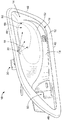
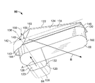
図1は、例示的な実施形態によって形成されたハンドル組立体10を示す。図示の実施形態では、ハンドル組立体10は、自動車で使用される自動車用ハンドル組立体である。但し、本願に記載の主題は、自動車用ハンドル組立体以外の異なる用途で使用することもできる。
FIG. 1 shows a
ハンドル組立体10は、ドアパネル内に嵌合するように構成されたベゼル12を含む。ベゼル12は、キャビティ壁16によって画定されたハンドルキャビティ14を有する。キャビティ壁16は、カップ状のハンドルキャビティ14を形成するように湾曲している。ベゼル12はまた、ハンドルキャビティ14へのアクセスを提供する開いた前面18を含む。スロット20は、キャビティ壁16を貫通して延在する。
The
ハンドル組立体10は、ドアパネルを開くためのハンドル22を含む。ハンドル22はハンドルキャビティ14内に通常位置決めされるが、ハンドル22の一部分がハンドルキャビティ14から延在してもよい。ハンドル22はキャビティ壁16を貫通しており、動作可能なように解除機構に結合される。なお、解除機構は、ドアを開くといった目的のためにドアパネルを解除するためのものである。ハンドル22は、ピボット端部24と自由端部26との間に延在する。動作の際には、乗員または操作者はハンドル22を把持し、かつハンドルキャビティ14からハンドル22を引っ張って、ドアを開く。ハンドル22を引っ張ると、ハンドル22はピボット端部24の周りを回転する。ハンドルキャビティ14は、ハンドル22とキャビティ壁16との間に、操作者の手がハンドル22を把持するのに十分な空間または隙間を提供する。
The
ハンドル組立体10は、ベゼル12に取り付けられたランプ組立体30を含む。ランプ組立体30の一部分は、ランプ組立体30からの光がハンドルキャビティ14内に照らされるように、スロット20と位置合わせされる。例示的な実施形態では、ランプ組立体30は、ハンドルキャビティ14内への光を対象領域へ制御しかつ誘導するように構成される。
The
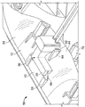
図2は、ハンドル組立体10の一部分を示す斜視図であるが、理解を容易にするためにハンドル22(図1に示す)を取り除いてある。また、図2はハンドル組立体10を示すが、図1に示すハンドル組立体10とは反対側のドア用のものである。図2は、ベゼル12およびランプ組立体30を示す。典型的な適用形態では、ベゼル12は、ハンドル22の向きがほぼ水平になるように、ドアパネルに結合される。ハンドル組立体10の構成要素については、そのような向きを基準として説明する。但し、代替実施形態では異なる向きとすることが可能であり、上部、底部、前方、後方、上方、下方などの相対位置を説明する用語は、ほぼ水平の構成をもつ実施形態に関係することが理解される。
FIG. 2 is a perspective view of a portion of the
ベゼル12は、上部40と、底部42と、前面18の反対側の裏面44とを含む。ベゼル12はまた、第1の端部46と、第2の端部48とを含む。ハンドル開口部50は、第1の端部46近傍でキャビティ壁16を貫通して延在する。ハンドル22は、ハンドル開口部50を通ってハンドルキャビティ14内へ延びるように構成される。ハンドル22は、ハンドル22のピボット端部24が第1の端部46近傍に位置し、また自由端部26が第2の端部48近傍に位置するように、キャビティ14内に位置決めされる。ベゼル12は、内部表面52と、外部表面54(図3に示す)とを含む。内部表面52によって、キャビティ14が画定される。
The
例示的な実施形態では、スロット20は、ベゼル12の上部40近傍に設けられる。ランプ組立体30は、ランプ組立体30の一部分がスロット20内に延びるように、ベゼル12の上部40に取り付けられる。ランプ組立体30は、キャビティ14内へ光を誘導して、キャビティ壁16を照らす。例示的な実施形態では、ランプ組立体30は、光を主対象領域56へ誘導する。ランプ組立体30はまた、主対象領域56を包含する副領域58も照らす。例示的な実施形態では、主対象領域56が副領域58よりも一層照らされるように、ランプ組立体30によって集光される。例示的な実施形態では、ランプ組立体30は、ハンドル22に向けて、および/または前面18を通して光を誘導するのではなく、裏面44へ向けてほぼ後方に光を誘導する。なお、主対象領域56を、上部40よりも底部42に近く、かつ第1の端部46より第2の端部48に近くなるように位置決めしてもよい。このようにして、キャビティ14のうちのハンドル22の自由端部26に近い領域が、キャビティ14の他の部分よりも一層照らされる。代替実施形態では、ランプ組立体30の構成を異なるものとすることができ、例えば異なる対象領域へ向けて、異なる方法で光を誘導するようにしてもよい。また、対象領域は、用途によって異なってもよい。
In the exemplary embodiment,
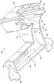
図3は、ハンドル組立体10の背面斜視図であり、ベゼル12およびランプ組立体30を示す。ランプ組立体30は、ベゼル12の外部表面54に取り付けられる。図示の実施形態では、ランプ組立体30は、ベゼル12の上部40近傍および裏面44近傍に取り付けられる。
FIG. 3 is a rear perspective view of the
ランプ組立体30は、複数のラッチ62を有するハウジング60を含む。複数のラッチ62は、ベゼル12から延びるリブ64に係合する。ハウジング60はまた、複数のタブ(tabs)66を含む。複数のタブ66は、ベゼル12から延びる留め具(catches)68に係合する。ハウジング60は、留め具68およびリブ64によって、ベゼル12に対して定位置に保持される。ベゼル12は、ベゼル12をドアパネル内に取り付けるために使用される複数の取付け機構(mounting features)70を含む。
The
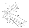
図4は、例示的なランプ組立体30の斜視図であり、ハウジング60を示す。ランプ組立体30は、ハウジング60内に保持された光パイプ80を含む。ランプ組立体30はまた、ハウジング60内に保持されたプリント回路基板(PCB)82を含む。例示的な実施形態では、光源84(図4に破線で示す)がPCB82に取り付けられる。複数のワイア86はPCB82にて終端し、光源84の動作を制御する。なお、フェルール(ferrules)または他の保持手段を使用することなどによって、ワイア86をハウジング60によって保持してもよい。また、ワイア86を定位置に固定するために、ハウジング60の壁の一部分を熱的に形成(thermally formed)したり、もしくは屈曲させてもよい。例示的な実施形態では、光源84は発光ダイオード(LED)であるが、代替実施形態では、他のタイプの光源を使用することもできる。光パイプ80が光源84と実質上位置合わせされ、かつ光源84から発せられた光を受光するように、光パイプ80はハウジング60内に配置される。光パイプ80は、光源84からの光をレンズ88へ誘導する。レンズ88は、ランプ組立体30がベゼル12(図1に示す)に取り付けられたとき、少なくともレンズ88の一部がスロット20(図1に示す)内へ延びるように構成される。なお、レンズ88は、光パイプ80と一体形成することができる。もしくは、レンズ88を、光パイプ80に結合させてもよい。
FIG. 4 is a perspective view of an
図5は、ランプ組立体30(図1に示す)のハウジング60を示す。ハウジング60は、内側表面90と、外側表面92と、前面94と、裏面96とを含む。ハウジング60がベゼル12(図1に示す)の上部に取り付けられる通常の適用形態では、内側表面90がハウジング60の底部を画定し、外側表面92がハウジング60の上部を画定する。ハウジング60はまた、第1の端部98と、第1の端部98とは反対側に位置する第2の端部100とを含む。
FIG. 5 shows the
ハウジング60は、PCBチャンバ102と、光パイプチャンバ104とを含む。チャンバ102、104は、ハウジング60内で互いに開いた状態である。PCBチャンバ102は、PCB82(図4に示す)を受容するように寸法設定されかつ成形される。また、PCBチャンバ102は、PCBチャンバ102内にPCB82を保持するための機構を含むことができる。たとえば、PCBチャンバ102を画定する壁内にタブを形成して、PCB82をPCBチャンバ102内に保持することができる。なお、PCB82をPCBチャンバ102内に固定するために、これらのタブおよび/またはPCBチャンバ102の壁を熱的に形成(thermally formed)したり、もしくは屈曲させてもよい。図示の実施形態では、ラッチ62が、ハウジング60上かつPCBチャンバ102近傍に設けられる。ラッチ62が可動性または可撓性を有することができるように、ハウジング60内かつラッチ62近傍に、スロット106が設けられる。
The
光パイプチャンバ104は、光パイプ80(図4に示す)を受容する。光パイプチャンバ104は、ベゼル12(図1に示す)に面しさらにはベゼル12上に載置される可能性がある光パイプ80の内側表面沿いを除き、光パイプ80を完全に収容するように構成される。したがって、光パイプチャンバ104は、光パイプ80から迷光が漏れてベゼル12から離れることを本質的に防止する。このように、光パイプチャンバ104は、光が光パイプ80から望ましくない方向へ漏れるのを阻止するための覆い(hood)として機能する。図示の実施形態では、光パイプチャンバ104はL字状であり、PCBチャンバ102から延びる第1の部分108と、第1の部分108からほぼ直角に延びる第2の部分110とを含む。第1の部分108は、ほぼ裏面96から前面94まで延在する。第2の部分110は前面94に設けられ、概ね第1の端部98から第2の端部100まで延在する。ハウジング60は、光パイプ80を光パイプチャンバ104内に保持するための複数の保持機構112を含む。図示の実施形態では、タブ66は、第1の端部98および第2の端部100の近傍で、ハウジング60の前面94から延在する。
The
図6および図7は、光パイプ80の正面斜視図である。光パイプ80は、内側表面120と、外側表面122と、前面124と、裏面126とを含む。光パイプ80がベゼル12(図1に示す)の上部に取り付けられる通常の適用形態では、内側表面120が光パイプ80の底部を画定し、外側表面122が光パイプ80の上部を画定する。光パイプ80は、第1の端部128と、第1の端部128とは反対側に位置する第2の端部130とをさらに含む。
6 and 7 are front perspective views of the
光パイプ80は、第1の脚部132と、第1の脚部132からある角度で延びる第2の脚部134とを含む。例示的な実施形態では、第2の脚部134は、第1の脚部132に概ね垂直である。但し、代替実施形態では、第2の脚部134は、直角ではない異なる角度で延在してもよい。第1の脚部132は、後端部138から前端部140まで、主軸136に沿って延在する。例示的な実施形態では、光パイプ80は、第1の脚部132の後端部138が光源84近傍に位置決めされるように、ハウジング60(図4に示す)内に配置される。なお、光源84は、図6および図7において破線で示される。光源84によって発せられた光は、後端部138を通じて光パイプ80によって受光される。そして、当該光は、主軸136に沿ってかつ第1の脚部132の下方へ向けて、後端部138から前端部140まで誘導される。その照射方向は、例えば矢印Aによって示される。第2の脚部134は、第1の脚端部144から第2の脚端部146まで、副軸142に沿って延在する。第1の脚端部144は、光パイプ80の第1の端部128近傍に位置決めされる。もしくは、第1の脚端部144を、第1の端部128に位置決めしてもよい。第2の脚端部146は、光パイプ80の第2の端部130の近傍に位置決めされる。もしくは、第2の脚端部146を、第2の端部130に位置決めしてもよい。第1の脚部132の下方へ誘導された光は、第1の脚部132から、概ね副軸142に沿った第2の脚部134に沿って、第2の脚端部146の方へ誘導される。その照射方向は、例えば矢印Bによって示される。主軸136と副軸142は、例示的な実施形態では概ね垂直であり、光パイプ平面(light pipe plane)148を画定する。光パイプ80がベゼル12上部に取り付けられる通常の適用形態では、光パイプ80と光パイプ平面148は、概ね水平にその向きが定められる。
The
例示的な実施形態では、光パイプ80は、傾斜した主反射面150を含む。主反射面150は、第1の脚部132と第2の脚部134とが交わる部分に設けられる。例示的な実施形態では、主反射面150は台形形状を有し、短い方の線分が概ね内側表面120に沿って位置し、長い方の線分が概ね外側表面122に沿って位置する。主反射面150は、第1の脚部132から第2の脚部134へ、最終的にはレンズ88を通じて光を誘導するように機能する。主反射面150の角度および向きが、光が誘導される角度を制御する。例示的な実施形態では、主反射面150は、主軸136に対して第1の角度152(図6に示す)で傾斜し、かつ副軸142に対して第2の角度154(図6に示す)で傾斜する。第1の角度152および第2の角度154は鋭角とすることができ、互いに異なる角度としてもよい。傾斜角152、154は、副軸142に対して、第2の脚部134の下方への光の方向を制御する。なお、傾斜角152、154を、副軸142とほぼ平行に光を誘導するように選択してもよい。但し、副軸142の横方向かつ副軸142をほぼ横切って、光が前方方向(たとえば、第2の脚部134の前面124の方)または後方方向(たとえば、第2の脚部134の裏面126の方)のいずれかに誘導されるように、傾斜角152、154の角度を選択してもよい。角度152、154を制御することによって、前方または後方のいずれかへ誘導される光の強度および量を制御しうる。
In the exemplary embodiment,
例示的な実施形態では、主反射面150は、横軸158に対して第3の角度156で傾斜する。横軸158は、光パイプ平面148に概ね垂直である。光パイプ平面148が概ね水平になるように光パイプ80が配置される通常の適用形態では、横軸158は概ね垂直である。傾斜角156は、副軸142に対して、第2の脚部134の下方へ向かう光の方向を制御する。なお、傾斜角156は、第2の脚部134における内側表面120へ向けて、概ね横軸158に沿って光を誘導するように選択してもよい。レンズ88は、第2の脚部134における内側表面120に沿って位置決めされる。したがって傾斜角156は、レンズ88へ向けて光を誘導するように選択される。傾斜角152、154、156は協働して、矢印Bによって示される放射光の向きを制御する。たとえば、例示的な実施形態では、放射光の向きは概ね下方であり、ハンドルキャビティ14(図2に示す)内へ放射される。また、キャビティ壁16(図2に示す)へ向かって概ね後方に放射され、ベゼル12(図2に示す)の第2の端部48へ向かって概ね外側に放射される。このように、光パイプ80からレンズ88を通じて放射された光を、対象領域56(図2に示す)に集光させることができる。
In the exemplary embodiment, main
例示的な実施形態では、第2の脚部134における外側表面122は、第1の脚端部144の近傍から第2の脚端部146まで、第2の脚部134に沿って内側表面120に向かって傾斜している。このように、第2の脚部134は、第2の脚端部146でより肉薄になる。外側表面122に傾斜をつけることによって、第2の脚部134の下方へ誘導される光のうち、主反射面150によってレンズ88の方へ誘導されない光が、外側表面122によってレンズ88の方へ誘導される。このように、第2の脚部134における外側表面122は、副反射面として機能する。光パイプ80の他の表面もまた、光パイプ80において光を再誘導するための副反射面として機能することができる。例示的な実施形態では、光パイプ80の外部表面は、光パイプ80内の光を反射するように構成され、その結果、光パイプ80は、全反射(total internal reflection)を受ける。レンズ88によって、レンズ88からの光放射が可能となる。例示的な実施形態では、レンズ88は傾斜面160を含む。この傾斜面は、レンズ88の前部から後部に向けて傾斜している。レンズ88の前部は、レンズ88の後部より低背である。傾斜面160を使用することで、レンズ88からの光を制御しながら誘導することができる。なお、レンズ88を湾曲させてもよい。
In the exemplary embodiment, the
例示的な組立体および動作について、前述の図を参照して説明する。ハンドル組立体10は、ベゼル12の外部に取り付けられたランプ組立体30を含む。光パイプ80およびPCB82は、ハウジング60をベゼル12に取り付ける前に、ハウジング60内に予め装填することができる。光パイプ80およびPCB82がそれぞれのチャンバ102、104内に装填されると、光パイプ80は光源84と位置合わせされ、光源84からの光を受光する。なお、光パイプ80は、PCB82に取り付けることができ、および/または光パイプ80と光源84とを一体形成しかつ1ユニットとしてハウジング60内に装填することができる。ハウジング60内部の組み立て終了後、ハウジング60はベゼル12に取り付けられ、レンズ88はベゼル12内のスロット20と位置合わせされる。なお、レンズ88は、スロット20内に延在し、および/またはスロット20を貫通することができる。摩擦嵌合などによって、レンズ88をスロット20内に保持することができる。例示的な実施形態では、レンズ88がベゼル12の上部40に位置決めされるように、ランプ組立体30をベゼル12に取り付ける。レンズ88は、ハンドル22の概ね垂直上方に、かつ第1の端部46と第2の端部48との間でほぼ中央に配置することができる。
Exemplary assembly and operation will be described with reference to the previous figures. The
動作中は、光源84を起動させて光を生成する。光は、光パイプ80の第1の脚部132における後端部138を通じて光パイプ80内に誘導される。光は、主軸136に沿って、前端部140および前端部140にある主反射面150の方へ誘導される。主反射面150は、光の方向を変化させ、第2の脚部134の下方へ光を誘導する。主反射面150は、ランプ組立体30の照光角度を制御し、光が対象領域56へ集光されるように、第1の照射方向に対して所定の向きで傾斜している。なお、第1の照射方向は、図6および図7における矢印Aによって示される。例示的な実施形態では、主反射面150は、レンズ88を通過する光の前方および/または後方への向き(たとえばベゼル12の前面18または裏面44への照光角度)を制御するために、傾斜角152、154で傾斜している。たとえば、傾斜角152、154を大きくすることによって、より後方へ(たとえば、ベゼル12の裏面44に向けて)光を誘導することができる。もしくは、傾斜角152、154を小さくすることによって、より前方へ(たとえば、ベゼル12の前面18に向けて)光を誘導することができる。例示的な実施形態では、主反射面150は、レンズ88を通過する光の下方への向き(たとえば、ベゼル12の底部42への照光角度)を制御するために、傾斜角156で傾斜している。たとえば、傾斜角156を大きくすることによって、より垂直に下方へ光を誘導することができる。もしくは傾斜角156を小さくすることによって、ベゼル12における第2の端部48へ向けて、さらに外側に光を誘導することができる。
During operation, the
このように、ハンドル組立体10は、ハンドル組立体10のハンドルキャビティ14を照らすためのランプ組立体30を備える。ランプ組立体は主反射面150を有する光パイプ80を含み、主反射面150によって光パイプ80の照光角度が制御される。主反射面150はある角度で傾斜して照光角度を制御し、これにより光を対象領域56へ集光する。例示的な実施形態では、対象領域56は、キャビティ壁16へ向かって概ね後方に位置し、かつベゼル12における第2の端部48へ向かって外側に位置する。このように、ハンドル22の自由端部26近傍など、ベゼルのうち乗員にとって最もよく見える部分が最も強い光で照らされ、その対象領域の周囲の領域はより弱い光で照らされる。このため、照光度が増すか、および/または、ベゼル12を照らすのにより小型の、および/またはより少電力型の光源を使用することができる。こうして、ランプ組立体30は、費用効果が高くかつ信頼性が高い形で提供される。
Thus, the
上記の説明は例示的なものであり、本発明を限定するものではないことを理解されたい。たとえば、前述の実施形態(および/またはその態様)を、互いに組み合せて使用することができる。さらに、本発明の範囲から逸脱することなく、特定の状況または材料を本発明の教示に適合させるために、多くの修正を加えることができる。本願に記載の寸法、材料の種類、様々な構成要素の向き、ならびに様々な構成要素の数および位置は、特定の実施形態のパラメータを規定するものであり、決して本発明を限定するものではなく、単なる例示的な実施形態にすぎない。上述した説明を検討すれば、特許請求の範囲の精神およびその範囲内で、他の多くの実施形態および修正形態が当業者には明らかになるであろう。したがって、本発明の範囲は添付の特許請求の範囲を参照して決定されるべきであるが、その際にはそのような特許請求の範囲に対して認められる均等物の全範囲も参照される。添付の特許請求の範囲では、「including」および「in which」という用語は、それぞれ「comprising」、「wherein」という用語の平易な英語として使用されるが、意味は等しい。さらに、以下の特許請求の範囲では、「第1」、「第2」、および「第3」などの用語は、単なる標識として使用するにすぎず、これらの用語の対象に対して数値的な要件を課すものではない。さらに、以下に示す特許請求の範囲の限定は、ミーンズ・プラス・ファンクション形式で記載されたものではない。当該限定が「手段(means for)」というフレーズを明示的に使用し、かつ、機能(ファンクション)についての言及がさらなる構造を欠いたまま当該フレーズに続かない限り、米国特許法(35 U.S.C.)第112条の第6段落に基づいて解釈されるものではない。
It should be understood that the above description is illustrative and not restrictive. For example, the above-described embodiments (and / or aspects thereof) can be used in combination with each other. In addition, many modifications may be made to adapt a particular situation or material to the teachings of the invention without departing from the scope of the invention. The dimensions, material types, the orientation of the various components, and the number and location of the various components described herein define the parameters of the particular embodiment and are not intended to limit the invention in any way. This is merely an exemplary embodiment. Many other embodiments and modifications will be apparent to those skilled in the art upon reviewing the above description and within the spirit and scope of the claims. Accordingly, the scope of the invention should be determined with reference to the appended claims, along with the full scope of equivalents to which such claims are entitled. . In the appended claims, the terms “including” and “in which” are used as plain English for the terms “comprising” and “wherein”, respectively, but are equivalent in meaning. Further, in the following claims, terms such as “first”, “second”, and “third” are merely used as labels and are numerical for the subject of these terms. It does not impose requirements. Further, the following limitations of the claims are not described in means-plus-function format. Unless the limitation explicitly uses the phrase “means for” and a reference to function does not follow the phrase without lack of further structure, it is subject to US patent law (35 US C.) It shall not be construed based on the sixth paragraph of
10 ハンドル組立体
12 ベゼル
14 ハンドルキャビティ
16 キャビティ壁
18 開いた前面
20 スロット
22 ハンドル
30 ランプ組立体
40 上部
42 底部
44 裏面
46 第1の端部
48 第2の端部
50 開口部
52 内部表面
54 外部表面
60 ハウジング
80 光パイプ
88 レンズ
120 内側表面
122 外側表面
132 第1の脚部
134 第2の脚部
136 主軸
142 副軸
148 光パイプ平面
150 主反射面
158 横軸
DESCRIPTION OF
Claims (11)
前記スロット(20)の近傍で前記ベゼル(12)に取り付けられたランプ組立体(30)とを備え、
前記ランプ組立体(30)は、ハウジング(60)と、前記ハウジングによって保持される光パイプ(80)とを含み、
前記光パイプ(80)が、主軸(136)に沿って延びる第1の脚部(132)と、前記主軸に対して概ね垂直な副軸(142)に沿って延びる第2の脚部(134)とを含み、
前記第2の脚部(134)が、前記第2の脚部における内側表面(120)に沿ってレンズ(88)を有するとともに、
光が、前記光パイプ(80)を通じて前記主軸(136)に沿って、前記第1の脚部と前記第2の脚部とが交わる部分に設けられた主反射面(150)へ誘導され、
前記主反射面(150)が、前記第2の脚部(134)に沿って前記レンズ(88)の方へ光を誘導する、ハンドル組立体(10)。 A handle cavity (14) defined by a cavity wall (16), an open front surface (18) that provides access to the handle cavity, and a slot (20) that extends through the cavity wall of the handle cavity. Bezel (12),
A lamp assembly (30) attached to the bezel (12) in the vicinity of the slot (20);
The lamp assembly (30) includes a housing (60) and a light pipe (80) held by the housing;
The light pipe (80) has a first leg (132) extending along a main axis (136) and a second leg (134) extending along a minor axis (142) generally perpendicular to the main axis. ) And
The second leg (134) has a lens (88) along an inner surface (120) in the second leg;
Light is guided along the main axis (136) through the light pipe (80) to a main reflecting surface (150) provided at a portion where the first leg and the second leg intersect.
A handle assembly (10), wherein the main reflective surface (150) guides light toward the lens (88) along the second leg (134).
前記主反射面(150)が、前記主軸(136)、前記副軸(142)、および前記横軸(158)のそれぞれと非平行に配置される、請求項1に記載のハンドル組立体。 The light pipe (80) further extends along a transverse axis (158) perpendicular to the major axis (136) and the minor axis (142);
The handle assembly according to claim 1, wherein the main reflective surface (150) is disposed non-parallel to each of the main axis (136), the counter axis (142), and the transverse axis (158).
前記主反射面(150)が、前記光パイプ平面(148)を横切って位置し、前記光パイプ平面の外へ光を誘導する、請求項1に記載のハンドル組立体。 The major axis (136) and the minor axis (142) define a light pipe plane (148);
The handle assembly of claim 1, wherein the main reflective surface (150) is located across the light pipe plane (148) and directs light out of the light pipe plane.
前記ランプ組立体(30)が、前記ベゼル外部表面(54)に取り付けられるとともに、
前記光パイプ(80)からの前記光が、前記ベゼル内部表面(52)を照らす、請求項1に記載のハンドル組立体。 The cavity wall (16) includes a bezel inner surface (52) and a bezel outer surface (54);
The lamp assembly (30) is attached to the bezel outer surface (54);
The handle assembly of claim 1, wherein the light from the light pipe (80) illuminates the bezel internal surface (52).
前記ランプ組立体(30)が、前記主軸(136)が概ね前記裏面から前記前面の方向に延びるように、前記ベゼルの前記上部に取り付けられ、
前記光パイプ(80)が、概ね前記底部および前記裏面の方へ光を誘導する、請求項6に記載のハンドル組立体。 The bezel (12) includes a top (40), a bottom (42), and a back surface (44) located opposite the front surface;
The lamp assembly (30) is attached to the top of the bezel such that the main shaft (136) extends generally from the back to the front;
The handle assembly of claim 6, wherein the light pipe (80) guides light generally toward the bottom and the back surface.
前記ベゼルが、前記第1の端部(46)の近傍に、ハンドル(22)を受容するように構成された開口部(50)を有し、
前記副軸(142)が、概ね前記第1の端部(46)から前記第2の端部(48)の方向に延び、
前記光パイプ(80)が、概ね前記底部および前記第2の端部の方へ光を誘導する、請求項6に記載のハンドル組立体。 The bezel (12) includes a top (40), a bottom (42), a first end (46), and a second end (48);
The bezel has an opening (50) configured to receive a handle (22) in the vicinity of the first end (46);
The countershaft (142) extends generally from the first end (46) to the second end (48);
The handle assembly of claim 6, wherein the light pipe (80) guides light generally toward the bottom and the second end.
前記第2の脚部(134)における前記外側表面(122)が、前記第1の脚部(132)から前記第2の端部(130)へ、前記内側表面(120)の方へ傾斜し、
前記第2の脚部(134)における前記外側表面(122)が、前記第2の脚部(134)における前記内側表面(120)の方へ光を誘導する、請求項1に記載のハンドル組立体。 The light pipe (80) further comprises an outer surface (122);
The outer surface (122) of the second leg (134) is inclined from the first leg (132) to the second end (130) toward the inner surface (120). ,
The handle set of claim 1, wherein the outer surface (122) of the second leg (134) guides light toward the inner surface (120) of the second leg (134). Solid.
前記ハウジング(60)が、前記光パイプの前記内側表面(120)のみが露出するように前記光パイプ(80)を覆う、請求項1に記載のハンドル組立体。 The lamp assembly (30) includes a housing (60);
The handle assembly of claim 1, wherein the housing (60) covers the light pipe (80) such that only the inner surface (120) of the light pipe is exposed.
Applications Claiming Priority (2)
| Application Number | Priority Date | Filing Date | Title |
|---|---|---|---|
| US12/177,407 | 2008-07-22 | ||
| US12/177,407 US7866860B2 (en) | 2008-07-22 | 2008-07-22 | Handle assembly with controlled light distribution |
Publications (2)
| Publication Number | Publication Date |
|---|---|
| JP2010043524A true JP2010043524A (en) | 2010-02-25 |
| JP5388117B2 JP5388117B2 (en) | 2014-01-15 |
Family
ID=41428954
Family Applications (1)
| Application Number | Title | Priority Date | Filing Date |
|---|---|---|---|
| JP2009169989A Expired - Fee Related JP5388117B2 (en) | 2008-07-22 | 2009-07-21 | Light distribution controlled handle assembly and lamp assembly |
Country Status (4)
| Country | Link |
|---|---|
| US (1) | US7866860B2 (en) |
| JP (1) | JP5388117B2 (en) |
| CA (1) | CA2671009C (en) |
| DE (1) | DE102009033880A1 (en) |
Cited By (1)
| Publication number | Priority date | Publication date | Assignee | Title |
|---|---|---|---|---|
| US20160138304A1 (en) * | 2013-06-21 | 2016-05-19 | Aisin Seiki Kabushiki Kaisha | Vehicle door handle |
Families Citing this family (12)
| Publication number | Priority date | Publication date | Assignee | Title |
|---|---|---|---|---|
| US8147110B2 (en) * | 2008-03-20 | 2012-04-03 | Tyco Electronics Canada Ulc | Light pipe assembly |
| JP5664425B2 (en) * | 2011-04-13 | 2015-02-04 | トヨタ紡織株式会社 | LIGHTING DEVICE FOR VEHICLE AND LIGHT SOURCE UNIT |
| USD874243S1 (en) * | 2011-06-21 | 2020-02-04 | Jaguar Land Rover Limited | Vehicle door handle |
| EP3667001B1 (en) * | 2012-09-07 | 2023-05-10 | U-Shin Italia S.p.A. | Vehicle panel handle lever |
| JP5955303B2 (en) * | 2013-11-19 | 2016-07-20 | 株式会社小糸製作所 | Door handle |
| US9389426B2 (en) | 2013-11-22 | 2016-07-12 | Tyco Electronics Canada Ulc | Light consolidation assembly |
| DE102014007970A1 (en) * | 2014-05-31 | 2015-12-03 | GM Global Technology Operations LLC (n. d. Ges. d. Staates Delaware) | Door inner opener for a motor vehicle door |
| USD859955S1 (en) * | 2016-02-25 | 2019-09-17 | Southco, Inc. | Latch actuator |
| JP6832163B2 (en) * | 2017-01-11 | 2021-02-24 | 株式会社ホンダアクセス | Door handle |
| AT521761B1 (en) * | 2018-10-02 | 2021-04-15 | MAN TRUCK & BUS OESTERREICH GesmbH | Illuminated interior door handle device for actuating a lock of a door of a vehicle from the inside |
| USD939917S1 (en) * | 2020-02-25 | 2022-01-04 | Paccar Inc | Door release |
| USD939314S1 (en) * | 2020-02-25 | 2021-12-28 | Paccar Inc | Door release |
Citations (4)
| Publication number | Priority date | Publication date | Assignee | Title |
|---|---|---|---|---|
| JP2005282205A (en) * | 2004-03-30 | 2005-10-13 | Honda Lock Mfg Co Ltd | Door handle device for car |
| JP2006009352A (en) * | 2004-06-24 | 2006-01-12 | Aisin Seiki Co Ltd | Vehicular door opening/closing device |
| JP2006138129A (en) * | 2004-11-12 | 2006-06-01 | Toyoda Gosei Co Ltd | Outside handle of vehicle |
| JP2008117637A (en) * | 2006-11-02 | 2008-05-22 | Jst Mfg Co Ltd | Thin connector with light guide |
Family Cites Families (8)
| Publication number | Priority date | Publication date | Assignee | Title |
|---|---|---|---|---|
| US2308844A (en) * | 1939-11-16 | 1943-01-19 | August E Wilshusen | Direction indicator |
| US6164805A (en) * | 1998-04-20 | 2000-12-26 | Federal-Mogul World Wide, Inc. | Illuminated door handle for a vehicle |
| US7374319B2 (en) * | 2001-10-31 | 2008-05-20 | Itc, Incorporated | Lighted handle |
| JP2005038831A (en) * | 2003-07-03 | 2005-02-10 | Olympus Corp | Optical apparatus, illumination device, and color illumination device |
| US7270452B2 (en) * | 2005-10-18 | 2007-09-18 | Yu Lin Enterprise Co., Ltd | Light emitting handle for vehicle |
| US7240452B2 (en) * | 2005-11-23 | 2007-07-10 | Shu-Li Ho | Structure for fixing a gun scope |
| US7635210B2 (en) * | 2005-12-23 | 2009-12-22 | Ford Global Technologies, Llc | Illuminated door handle |
| US7400232B2 (en) * | 2006-05-11 | 2008-07-15 | Trimark Corporation | Illuminated vehicle grab handle with keypad for keyless entry |
-
2008
- 2008-07-22 US US12/177,407 patent/US7866860B2/en not_active Expired - Fee Related
-
2009
- 2009-07-07 CA CA2671009A patent/CA2671009C/en not_active Expired - Fee Related
- 2009-07-20 DE DE102009033880A patent/DE102009033880A1/en not_active Withdrawn
- 2009-07-21 JP JP2009169989A patent/JP5388117B2/en not_active Expired - Fee Related
Patent Citations (4)
| Publication number | Priority date | Publication date | Assignee | Title |
|---|---|---|---|---|
| JP2005282205A (en) * | 2004-03-30 | 2005-10-13 | Honda Lock Mfg Co Ltd | Door handle device for car |
| JP2006009352A (en) * | 2004-06-24 | 2006-01-12 | Aisin Seiki Co Ltd | Vehicular door opening/closing device |
| JP2006138129A (en) * | 2004-11-12 | 2006-06-01 | Toyoda Gosei Co Ltd | Outside handle of vehicle |
| JP2008117637A (en) * | 2006-11-02 | 2008-05-22 | Jst Mfg Co Ltd | Thin connector with light guide |
Cited By (2)
| Publication number | Priority date | Publication date | Assignee | Title |
|---|---|---|---|---|
| US20160138304A1 (en) * | 2013-06-21 | 2016-05-19 | Aisin Seiki Kabushiki Kaisha | Vehicle door handle |
| US10501966B2 (en) * | 2013-06-21 | 2019-12-10 | Aisin Seiki Kabushiki Kaisha | Vehicle door handle |
Also Published As
| Publication number | Publication date |
|---|---|
| CA2671009A1 (en) | 2010-01-22 |
| CA2671009C (en) | 2016-06-07 |
| DE102009033880A1 (en) | 2010-01-28 |
| US7866860B2 (en) | 2011-01-11 |
| JP5388117B2 (en) | 2014-01-15 |
| US20100020558A1 (en) | 2010-01-28 |
Similar Documents
| Publication | Publication Date | Title |
|---|---|---|
| JP5388117B2 (en) | Light distribution controlled handle assembly and lamp assembly | |
| JP4508172B2 (en) | Vehicle room lamp | |
| US11486557B2 (en) | Vehicle lamp, lamp unit, and reflector module | |
| JP3638846B2 (en) | Vehicle headlamp | |
| JP2014041813A (en) | Linear lighting device | |
| JP2008053065A (en) | Vehicular room lamp | |
| JP5690971B2 (en) | Lighting device for vehicle interior | |
| CN116157626A (en) | Lamp for vehicle | |
| JP5987681B2 (en) | Linear lighting device | |
| US8297813B2 (en) | Vehicular lamp | |
| JP2019061905A (en) | Moving body illuminating device and moving body | |
| JP6120138B2 (en) | License plate lighting device | |
| CN112432128B (en) | Vehicle lamp | |
| JP2011121504A (en) | Vehicle lighting system | |
| JP2009073290A (en) | Indoor lighting system for vehicle, and indoor lighting structure for vehicle | |
| JP5589930B2 (en) | Lighting device | |
| WO2021193556A1 (en) | Vehicular lamp | |
| CN211232731U (en) | Vehicle lamp | |
| CN220249740U (en) | Car light structure and car | |
| JP7066416B2 (en) | Handrail Kasagi | |
| JP5794351B2 (en) | Lighting device | |
| JP2006196239A (en) | Light emitting device | |
| JP2017098197A (en) | Heat radiation structure | |
| JP2000057803A5 (en) | ||
| JP4045720B2 (en) | Vehicle lighting |
Legal Events
| Date | Code | Title | Description |
|---|---|---|---|
| A621 | Written request for application examination |
Free format text: JAPANESE INTERMEDIATE CODE: A621 Effective date: 20120413 |
|
| A131 | Notification of reasons for refusal |
Free format text: JAPANESE INTERMEDIATE CODE: A131 Effective date: 20130130 |
|
| A977 | Report on retrieval |
Free format text: JAPANESE INTERMEDIATE CODE: A971007 Effective date: 20130131 |
|
| A521 | Written amendment |
Free format text: JAPANESE INTERMEDIATE CODE: A523 Effective date: 20130412 |
|
| TRDD | Decision of grant or rejection written | ||
| A01 | Written decision to grant a patent or to grant a registration (utility model) |
Free format text: JAPANESE INTERMEDIATE CODE: A01 Effective date: 20131002 |
|
| A61 | First payment of annual fees (during grant procedure) |
Free format text: JAPANESE INTERMEDIATE CODE: A61 Effective date: 20131002 |
|
| R150 | Certificate of patent or registration of utility model |
Free format text: JAPANESE INTERMEDIATE CODE: R150 |
|
| R250 | Receipt of annual fees |
Free format text: JAPANESE INTERMEDIATE CODE: R250 |
|
| LAPS | Cancellation because of no payment of annual fees |