JP2010042994A - Apparatus for homogenizing molten glass by stirring - Google Patents
Apparatus for homogenizing molten glass by stirring Download PDFInfo
- Publication number
- JP2010042994A JP2010042994A JP2009239112A JP2009239112A JP2010042994A JP 2010042994 A JP2010042994 A JP 2010042994A JP 2009239112 A JP2009239112 A JP 2009239112A JP 2009239112 A JP2009239112 A JP 2009239112A JP 2010042994 A JP2010042994 A JP 2010042994A
- Authority
- JP
- Japan
- Prior art keywords
- stirring
- glass
- chamber
- agitation
- stirring means
- Prior art date
- Legal status (The legal status is an assumption and is not a legal conclusion. Google has not performed a legal analysis and makes no representation as to the accuracy of the status listed.)
- Granted
Links
Images


Classifications
-
- C—CHEMISTRY; METALLURGY
- C03—GLASS; MINERAL OR SLAG WOOL
- C03B—MANUFACTURE, SHAPING, OR SUPPLEMENTARY PROCESSES
- C03B5/00—Melting in furnaces; Furnaces so far as specially adapted for glass manufacture
- C03B5/16—Special features of the melting process; Auxiliary means specially adapted for glass-melting furnaces
- C03B5/18—Stirring devices; Homogenisation
- C03B5/187—Stirring devices; Homogenisation with moving elements
-
- B—PERFORMING OPERATIONS; TRANSPORTING
- B01—PHYSICAL OR CHEMICAL PROCESSES OR APPARATUS IN GENERAL
- B01F—MIXING, e.g. DISSOLVING, EMULSIFYING OR DISPERSING
- B01F27/00—Mixers with rotary stirring devices in fixed receptacles; Kneaders
- B01F27/05—Stirrers
- B01F27/11—Stirrers characterised by the configuration of the stirrers
- B01F27/112—Stirrers characterised by the configuration of the stirrers with arms, paddles, vanes or blades
- B01F27/1123—Stirrers characterised by the configuration of the stirrers with arms, paddles, vanes or blades sickle-shaped, i.e. curved in at least one direction
-
- B—PERFORMING OPERATIONS; TRANSPORTING
- B01—PHYSICAL OR CHEMICAL PROCESSES OR APPARATUS IN GENERAL
- B01F—MIXING, e.g. DISSOLVING, EMULSIFYING OR DISPERSING
- B01F27/00—Mixers with rotary stirring devices in fixed receptacles; Kneaders
-
- B—PERFORMING OPERATIONS; TRANSPORTING
- B01—PHYSICAL OR CHEMICAL PROCESSES OR APPARATUS IN GENERAL
- B01F—MIXING, e.g. DISSOLVING, EMULSIFYING OR DISPERSING
- B01F27/00—Mixers with rotary stirring devices in fixed receptacles; Kneaders
- B01F27/05—Stirrers
- B01F27/11—Stirrers characterised by the configuration of the stirrers
- B01F27/115—Stirrers characterised by the configuration of the stirrers comprising discs or disc-like elements essentially perpendicular to the stirrer shaft axis
- B01F27/1152—Stirrers characterised by the configuration of the stirrers comprising discs or disc-like elements essentially perpendicular to the stirrer shaft axis with separate elements other than discs fixed on the discs, e.g. vanes fixed on the discs
-
- B—PERFORMING OPERATIONS; TRANSPORTING
- B01—PHYSICAL OR CHEMICAL PROCESSES OR APPARATUS IN GENERAL
- B01F—MIXING, e.g. DISSOLVING, EMULSIFYING OR DISPERSING
- B01F27/00—Mixers with rotary stirring devices in fixed receptacles; Kneaders
- B01F27/50—Pipe mixers, i.e. mixers wherein the materials to be mixed flow continuously through pipes, e.g. column mixers
-
- C—CHEMISTRY; METALLURGY
- C03—GLASS; MINERAL OR SLAG WOOL
- C03B—MANUFACTURE, SHAPING, OR SUPPLEMENTARY PROCESSES
- C03B5/00—Melting in furnaces; Furnaces so far as specially adapted for glass manufacture
- C03B5/16—Special features of the melting process; Auxiliary means specially adapted for glass-melting furnaces
- C03B5/18—Stirring devices; Homogenisation
- C03B5/187—Stirring devices; Homogenisation with moving elements
- C03B5/1875—Stirring devices; Homogenisation with moving elements of the screw or pump-action type
-
- B—PERFORMING OPERATIONS; TRANSPORTING
- B01—PHYSICAL OR CHEMICAL PROCESSES OR APPARATUS IN GENERAL
- B01F—MIXING, e.g. DISSOLVING, EMULSIFYING OR DISPERSING
- B01F2215/00—Auxiliary or complementary information in relation with mixing
- B01F2215/04—Technical information in relation with mixing
- B01F2215/0409—Relationships between different variables defining features or parameters of the apparatus or process
-
- B—PERFORMING OPERATIONS; TRANSPORTING
- B01—PHYSICAL OR CHEMICAL PROCESSES OR APPARATUS IN GENERAL
- B01F—MIXING, e.g. DISSOLVING, EMULSIFYING OR DISPERSING
- B01F2215/00—Auxiliary or complementary information in relation with mixing
- B01F2215/04—Technical information in relation with mixing
- B01F2215/0413—Numerical information
- B01F2215/0436—Operational information
- B01F2215/044—Numerical composition values of components or mixtures, e.g. percentage of components
-
- B—PERFORMING OPERATIONS; TRANSPORTING
- B01—PHYSICAL OR CHEMICAL PROCESSES OR APPARATUS IN GENERAL
- B01F—MIXING, e.g. DISSOLVING, EMULSIFYING OR DISPERSING
- B01F27/00—Mixers with rotary stirring devices in fixed receptacles; Kneaders
- B01F27/80—Mixers with rotary stirring devices in fixed receptacles; Kneaders with stirrers rotating about a substantially vertical axis
Landscapes
- Chemical & Material Sciences (AREA)
- Chemical Kinetics & Catalysis (AREA)
- Engineering & Computer Science (AREA)
- Materials Engineering (AREA)
- Organic Chemistry (AREA)
- Mixers Of The Rotary Stirring Type (AREA)
- Glass Compositions (AREA)
Abstract
Description
本発明は、溶融ガラスの均一化に関し、特に、欠陥が低レベルである高品質の完成製品を製造するのに用いられる溶融ガラスの均一化に関する。本発明の特に重要な用途は、AMLCDの製造に用いられる基板などの液晶ディスプレイ用のガラス基板の製造である。 The present invention relates to the homogenization of molten glass, and more particularly to the homogenization of molten glass used to produce high quality finished products with low levels of defects. A particularly important application of the present invention is the manufacture of glass substrates for liquid crystal displays, such as substrates used in the manufacture of AMLCDs.
ガラスの化学的および熱的均一性は良好な成形操作の重大な要素である。ガラス溶融器の機能は一般に、気体または固体の含有物のレベルが許容範囲にあるガラスを製造することであるが、このようなガラスには通常化学的に相違した相の脈理(または糸状のすじまたは透しむら)がある。母材ガラスのこれらの不均一成分は、耐火物の分離、溶融の層理、ガラス表面の揮発、および温度差を含む溶融工程中の様々な普通の出来事から生じる。このように生じた脈理は、色および/または屈折率差のために母材ガラス中に見える。 The chemical and thermal uniformity of the glass is a critical element of a good molding operation. The function of a glass melter is generally to produce a glass with acceptable levels of gas or solid inclusions, but such glasses usually have chemically different phase striae (or filamentous). Streaks or see-through). These heterogeneous components of the base glass result from a variety of common events during the melting process including refractory separation, melting layering, glass surface volatilization, and temperature differences. The striae thus produced are visible in the base glass due to color and / or refractive index differences.
ガラスの均一性を改善する手法の一つは、溶融ガラスを溶融器の下流に設置された垂直に向けられた撹拌チャンバに通すことである。そのような撹拌チャンバは、適切なモータにより回転せしめられる中心軸を持つ撹拌手段を備えている。複数の羽根がこの軸から延在し、溶融ガラスが撹拌チャンバの頂部から底部まで通過するときにこれを混合するように働く。本発明は、そのような撹拌チャンバの動作に関し、特に、これにより製造されたガラスに欠陥を、特に、混合工程の結果として撹拌チャンバの壁および/または撹拌手段の表面の腐食から生じる欠陥を導入せずに、そのようなチャンバで高処理量および高混合効率(混合有効性)を達成することに関する。 One way to improve glass uniformity is to pass the molten glass through a vertically oriented stirring chamber located downstream of the melter. Such a stirring chamber comprises stirring means with a central axis that is rotated by a suitable motor. A plurality of vanes extend from this axis and serve to mix the molten glass as it passes from the top to the bottom of the stirring chamber. The invention relates to the operation of such a stirring chamber, in particular introducing defects in the glass produced thereby, in particular defects resulting from corrosion of the walls of the stirring chamber and / or the surface of the stirring means as a result of the mixing process. Without achieving high throughput and high mixing efficiency (mixing effectiveness) in such a chamber.
層流条件下で撹拌手段が何をしているかを想像する簡単な方法は、所望の組成または母材組成のガラスにより取り囲まれたその組成範囲外のガラスの塊として脈理を考えることである。各脈理片は、それ自体と母材ガラスとの間に界面を持つものとして考えられる。このガラスの総不均一性の尺度の一つは、脈理の全界面表面積である。界面表面積は、全ての脈理が一つの球状塊にあるときに最小になる。これらの塊が小さな部分に壊れ、平らな面に伸ばされると、脈理の容積は同じままであるにもかかわらず界面表面積は増す。撹拌の効率(ここでは、撹拌の有効性とも称される)の尺度の一つは、撹拌後の増加した界面表面積の撹拌前の界面表面積に対する比である。 A simple way to imagine what the agitation means is doing under laminar flow conditions is to consider the striae as a glass mass outside its composition range surrounded by glass of the desired composition or matrix composition. . Each striae is considered as having an interface between itself and the base glass. One measure of the total non-uniformity of this glass is the total interfacial surface area of the striae. The interfacial surface area is minimized when all striae are in one spherical mass. When these lumps break into small pieces and stretch to a flat surface, the interfacial surface area increases despite the striae volume remaining the same. One measure of stirring efficiency (also referred to herein as stirring effectiveness) is the ratio of increased interfacial surface area after stirring to interfacial surface area before stirring.
均一性を増すのに効果的であるためには、撹拌装置は、以下の三つの作用を果たすべきである:
(1) 不均一ガラスの塊を薄い筋状体に引き延ばすべきである。この作用のためには、ガラスに剪断応力を加える必要がある。
In order to be effective in increasing uniformity, the agitation device should perform three actions:
(1) The non-uniform glass mass should be stretched into thin streaks. For this action, it is necessary to apply shear stress to the glass.
(2) これらの筋状体を短いセグメントに切断すべきである。この作用は、溶融ガラスを撹拌手段の羽根の面に対して垂直な方向に流動させることにより実施できる。 (2) These streaks should be cut into short segments. This action can be carried out by causing the molten glass to flow in a direction perpendicular to the blade surface of the stirring means.
(3) パターンが認識できないように短いセグメントを分散させるべきである。この作用は、ガラスの主流方向に対して垂直にガラスを押す羽根形状を、すなわち、少なくともある程度ガラスを半径方向に流動させる羽根形状を選択することにより実施できる。 (3) Short segments should be distributed so that the pattern cannot be recognized. This action can be performed by selecting a blade shape that pushes the glass perpendicular to the main flow direction of the glass, that is, a blade shape that causes the glass to flow in the radial direction at least to some extent.
筋状体を薄くしそれらを切断することにより、筋状体が顕微鏡の尺度で個々に見ずらくなる。それらを分散させることにより、目に見えるパターンが顕微鏡の尺度で残される可能性がなくなる。 By thinning the streaks and cutting them, the streaks become difficult to see individually on a microscopic scale. Dispersing them eliminates the possibility of leaving visible patterns on a microscopic scale.
ガラスの流れが連続的である工程において、これらの三つの作用は、撹拌チャンバ内のガラスの滞留時間により決まる別々の時間間隔で行わなければならない。ガラスの流量が増すに連れて、ガラスにこれら三つの作用が行われるチャンバ内での時間が少なくなる。所望の流れの増加に対する通常の操作応答は、撹拌手段の速度の増加である。これにより、剪断応力、切断周期、および潜在的には分散率も増す。 In a process where the glass flow is continuous, these three actions must occur at separate time intervals determined by the residence time of the glass in the stirring chamber. As the flow rate of the glass increases, the time in the chamber where these three actions are performed on the glass decreases. The normal operating response to the desired increase in flow is an increase in the speed of the stirring means. This also increases shear stress, cutting period, and potentially dispersion.
もともとは、ガラス撹拌装置は、適度な撹拌手段の寿命と両立して、出来るだけ高い剪断応力を持つように設計されてきた。実際に、そのような装置は通常、低速で動作したときにさえ高剪断応力を生じるように設計されている。その目的は、撹拌装置の製造に使用されている貴金属(例えば、白金合金)の費用が高いために、最小の撹拌装置から最大の撹拌効果を得ることにある。一般論として、剪断応力は、羽根の速度を上昇させることにより、および/または撹拌手段の羽根と撹拌チャンバの壁との間の間隙を減少させることにより、増加する。 Originally, glass stirrers have been designed to have as high a shear stress as possible, in keeping with a moderate agitation means lifetime. In fact, such devices are usually designed to produce high shear stress even when operated at low speeds. The purpose is to obtain the maximum agitation effect from the minimum agitation device due to the high cost of noble metals (eg platinum alloys) used in the production of the agitation device. As a general rule, the shear stress is increased by increasing the speed of the blades and / or by reducing the gap between the blades of the stirring means and the walls of the stirring chamber.
多くのガラス製品(例えば、構造用ガラス)には、中程度の均一性要件のみが適用される。しかしながら、他のガラス製品は、厳しい均一性および他の品質基準を満たさなければならない。LCDガラスは、この後者の範疇にある。このガラスに関しては、脈理と含有物の両方を最小にするおよび/またはなくす必要がある。 For many glass products (eg, structural glass), only moderate uniformity requirements apply. However, other glass products must meet stringent uniformity and other quality standards. LCD glass is in this latter category. With this glass, both striae and inclusions need to be minimized and / or eliminated.
本発明によれば、LCDガラス製造プロセスにおいて、50マイクロメートル未満のサイズを持つ貴金属含有物(例えば、白金合金の含有物)がLCDガラスの製造中にそのガラス中に導入されることが発見された。これらの含有物は、撹拌チャンバに由来し、特に、粘性の溶融ガラスの中を通る撹拌手段の動きにより生じる粘性剪断応力の結果として、撹拌手段および撹拌チャンバの腐食に由来した。 In accordance with the present invention, it has been discovered that in the LCD glass manufacturing process, noble metal inclusions (eg, platinum alloy inclusions) having a size of less than 50 micrometers are introduced into the glass during LCD glass manufacture. It was. These inclusions originated from the stirrer chamber and, in particular, from corrosion of the stirrer and stirrer chamber as a result of the viscous shear stress caused by the movement of the stirrer through the viscous molten glass.
それゆえ、本発明の目的の一つは、溶融ガラスの撹拌中に貴金属含有物の生成を最小にすることにある。しかしながら、この主目的は、(1)高ガラス処理量を維持すること、および(2)高撹拌有効性(例えば、低レベルの脈理)を維持することの目的により補われる。これらの後者の目的および主目的は相反することである。例えば、撹拌手段の速度を減少させると、剪断応力、それゆえ腐食を減少させることができるが、撹拌手段の速度を減少させるということは、撹拌が効率的ではなくなるおよび/または処理量が減少することを意味する。 Therefore, one object of the present invention is to minimize the formation of noble metal inclusions during the stirring of the molten glass. However, this main objective is supplemented by the objectives of (1) maintaining high glass throughput and (2) maintaining high agitation effectiveness (eg, low levels of striae). These latter and main purposes are contradictory. For example, reducing the speed of the stirring means can reduce shear stress and hence corrosion, but reducing the speed of the stirring means makes stirring less efficient and / or reduces throughput. Means that.
以下に論じるように、本発明は、管半部材の速度、撹拌手段/撹拌チャンバの幾何学形状、およびガラスの粘度の関係によりこれらの矛盾すると思える目的を同時に達成することができるものであり、これらの関係により、撹拌有効性および処理量を、高剪断撹拌によってのみ以前に達成できていたレベルに維持すると同時に、剪断応力を、許容できない含有物が形成されるレベルより低く減少できる(例えば、撹拌手段および撹拌チャンバの壁に作用する剪断応力を3.5×10-3N/m2未満にできる)。 As discussed below, the present invention is able to achieve these contradictory objectives simultaneously due to the relationship of tube half speed, stirring means / stirring chamber geometry, and glass viscosity, These relationships allow the agitation effectiveness and throughput to be maintained at levels previously achievable only with high shear agitation while at the same time reducing the shear stress below the level at which unacceptable inclusions are formed (e.g., The shear stress acting on the stirring means and the walls of the stirring chamber can be less than 3.5 × 10 −3 N / m 2 ).
態様の一つによれば、本発明は、溶融ガラスを均一にする方法であって、
(a) 内径Dwallを持つ壁を備えた、円筒形状の実質的に垂直に向けられた撹拌チャンバを提供し、
(b) 実質的に垂直に向けられた軸と、軸から外側に撹拌チャンバの壁に向かって延在する、最大直径Dbladeを持つ複数の羽根とを備えた撹拌手段を撹拌チャンバ内に提供し、
(c) 粘度μを持つ溶融ガラスを撹拌チャンバに通して流動させ(例えば、少なくとも0.05キログラム毎秒の流量で)、
(d) 溶融ガラスがチャンバを通って流動するときに、撹拌手段の軸にトルクTを加えて、撹拌チャンバ内で撹拌手段を速度Nで回転させる、
各工程を有してなり、
ここで、チャンバ内の撹拌手段の回転が押しのけ容積Vを定義するものであり、
Nがラジアン毎秒で表され、Tがニュートン・メートルで表され、Vが立方メートルで表され、Dwallがメートルで表され、Dbladeがメートルで表され、μがkg/メートル・秒で表されている、N,T,V,Dwall、Dblade、およびμが、以下の関係式:
(NTV/μ)0.5≧5.0キログラム毎秒、および
(2πNDblade)/(Dwall−Dblade)≦3.5×10-3ニュートン/立方メートル
を満たすように選択されている方法を提供する。
According to one aspect, the present invention is a method for homogenizing molten glass, comprising:
(A) having a wall with an inner diameter D wall, it provides a substantially agitation chamber vertically oriented cylindrical,
(B) Providing a stirring means in the stirring chamber with a substantially vertically oriented shaft and a plurality of blades having a maximum diameter D blade extending outwardly from the shaft toward the wall of the stirring chamber And
(C) flowing molten glass having a viscosity μ through a stirring chamber (eg, at a flow rate of at least 0.05 kilograms per second);
(D) applying torque T to the shaft of the stirring means as the molten glass flows through the chamber and rotating the stirring means at a speed N in the stirring chamber;
Having each process,
Here, the rotation of the stirring means in the chamber defines the displacement volume V,
N is expressed in radians per second, T is expressed in Newton meters, V is expressed in cubic meters, D wall is expressed in meters, D blade is expressed in meters, and μ is expressed in kg / meter · second. N, T, V, D wall , D blade , and μ are the following relational expressions:
Provided are methods selected to satisfy (NTV / μ) 0.5 ≧ 5.0 kilograms per second, and (2πND blade ) / (D wall −D blade ) ≦ 3.5 × 10 −3 Newton / cubic meter.
第2の態様によれば、本発明は上述した方法を実施するための装置を提供する。 According to a second aspect, the present invention provides an apparatus for performing the method described above.
第3の態様によれば、本発明は、溶融ガラスを均一にするための装置であって、
(a) 壁を備えた円筒形状の実質的に垂直に向けられた撹拌チャンバ、および
(b) 実質的に垂直に向けられた軸と、軸から外側に撹拌チャンバの壁に向かって延在する複数の羽根とを備えた、撹拌チャンバ内の撹拌手段、
を備え、
撹拌チャンバが、撹拌チャンバから流出するガラスが流動方向の変化を経るような側部出口ポートを備え、撹拌手段が、流動方向が変化する領域においてガラスを撹拌するための少なくとも一つの部材を備え、少なくとも一つの部材が、撹拌手段の軸と実質的に平行であるが、同一直線上にはない縦軸を持つ装置を提供する。
According to a third aspect, the present invention is an apparatus for making molten glass uniform,
(A) a cylindrically shaped substantially vertically oriented stirring chamber with walls; and (b) a substantially vertically oriented shaft and extending outwardly from the shaft toward the wall of the stirring chamber. A stirring means in a stirring chamber comprising a plurality of blades;
With
The stirring chamber comprises a side outlet port through which the glass flowing out of the stirring chamber undergoes a change in flow direction, and the stirring means comprises at least one member for stirring the glass in the region where the flow direction changes; At least one member is provided which has a longitudinal axis which is substantially parallel to the axis of the stirring means but which is not collinear.
本発明の第3の態様を本発明の第1および/または第2の態様に使用することが好ましい。 It is preferred to use the third aspect of the present invention for the first and / or second aspects of the present invention.
本発明の上述した三つの態様の各々に関する好ましい用途は、液晶ディスプレイ用ガラスの製造である。この用途に使用する場合、10マイクロメートル未満のサイズの貴金属含有物(例えば、白金を含む含有物)の数は、完成ガラス1キログラム当たり20未満であることが好ましい。 A preferred application for each of the above-described three embodiments of the present invention is the production of glass for liquid crystal displays. When used in this application, the number of noble metal inclusions (eg, containing platinum) having a size of less than 10 micrometers is preferably less than 20 per kilogram of finished glass.
本発明に含まれ、本発明の一部を構成する図面は、本発明の様々な実施の形態を示しており、説明と共に、本発明の原理を説明するように働く。もちろん、図面および記載の両方は、説明のみのためであり、本発明を制限するものではないことを理解すべきである。 The drawings included in and forming a part of the invention illustrate various embodiments of the invention and, together with the description, serve to explain the principles of the invention. Of course, it is to be understood that both the drawings and the description are for illustration only and are not intended to limit the invention.
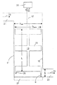
上述したように、本発明より前には、撹拌手段/撹拌チャンバの設計の根底にある理念は、高レベルの撹拌有効性を達成するように高レベルの剪断応力を発生させることにあった。剪断応力は、撹拌チャンバ11の壁19の近くで、撹拌手段の羽根15と壁との間の狭い間隙により、また羽根の速度により発生せしめられる。一般論として、撹拌手段の表面および撹拌チャンバの内面に作用する剪断応力τは、
|τ|=μdv/dx (1)
として表すことができ、ここで、μは溶融ガラスの粘度であり、vは流体の速度であり、xは剪断応力を経験する表面に対して垂直な方向にある。
As mentioned above, prior to the present invention, the underlying idea of the stirring means / stirring chamber design was to generate a high level of shear stress to achieve a high level of stirring effectiveness. The shear stress is generated near the
| Τ | = μdv / dx (1)
Where μ is the viscosity of the molten glass, v is the velocity of the fluid, and x is in the direction perpendicular to the surface experiencing the shear stress.
方程式(1)を、円筒形状の撹拌チャンバと、共通の直径Dbladeを持つ一つ以上の羽根を有する円対称の撹拌手段とに適用すると次式が得られる、
|τ|=μπNDblade/C (2)
ここで、Nはラジアン/秒で表した撹拌手段の速度であり、Cは羽根先端と撹拌チャンバの壁との間の結合距離である(すなわち、図1において、C=(Dwall−Dblade)/2)。キログラム/メートル・秒で表したμ、ラジアン/秒で表したN、およびメートルで表したDbladeとCに関して、τはニュートン/平方メートル(N/m2)で表されている。
Applying equation (1) to a cylindrical stirring chamber and a circularly symmetric stirring means having one or more blades with a common diameter D blade yields:
| Τ | = μπND blade / C (2)
Here, N is the speed of the stirring means expressed in radians / second, and C is the coupling distance between the blade tip and the wall of the stirring chamber (ie, in FIG. 1, C = (D wall −D blade ) / 2). For μ in kilograms / meter · second, N in radians / second, and D blade and C in meters, τ is expressed in Newtons per square meter (N / m 2 ).
上述し、以下に提示した実施例によって一層十分に示したように、本発明によれば、許容できないほど高いレベル(例えば、完成ガラス1キログラム当たり20より多い含有物のレベル)の含有物(例えば、10マイクロメートルより大きいサイズを持つ含有物)を生じるレベルの撹拌手段と撹拌チャンバの壁の腐食を避けるために、|τ|は、3.5×10⁻³N/m2未満、好ましくは、1.5×10-3N/m2未満に維持する必要がある。 As described above and more fully shown by the examples presented below, according to the present invention, an unacceptably high level of content (e.g., a level of content greater than 20 per kilogram of finished glass) (e.g. Is less than 3.5 × 10 −3 N / m 2 , preferably to avoid erosion of the stirrer means and stir chamber walls at levels that produce inclusions having a size greater than 10 micrometers) , 1.5 × 10 −3 N / m 2 must be maintained.
方程式(2)から、剪断応力のレベルは、Nを減少させる、および/またはDbladeを減少させる、および/またはCを増加させることにより、減少させられるのが分かる。しかしながら、最終的には、撹拌によって、実際的な流量で適切に均一にされたガラスを製造しなければならないので、単に剪断応力を減少させることは商業的に受け入れられない。したがって、実際的な装置にとって、剪断応力の減少は、撹拌有効性または流量を犠牲にして行うべきではない。 From equation (2) it can be seen that the level of shear stress can be reduced by decreasing N and / or decreasing D blade and / or increasing C. Ultimately, however, it is not commercially acceptable to simply reduce the shear stress, as agitation must produce a suitably uniformed glass at a practical flow rate. Thus, for practical devices, shear stress reduction should not be done at the expense of agitation effectiveness or flow rate.
様々な撹拌装置の物理的モデル、特に、オイルモデルにより、撹拌有効性(無次元量)について、以下の方程式を作成した:
E≒(kBDblade 2NV|τ|/Q2μ)0.5 (3)
ここで、kは撹拌手段/撹拌チャンバの幾何学形状に依存する定数であり、Qは流量であり、Bは羽根先端の数であり、Vは撹拌手段の押しのけ容積である。特に、撹拌挙動を研究すべきガラスの粘度となるように選択した粘度を持つ非流動性粘性オイルを充填した様々な実寸大の撹拌装置を用いて研究所規模の実験を行った。異なる粘度を持つ粘性オイルを用いて異なるガラスを表したか、または同じオイルを異なる温度で撹拌した。この作業により得られた量Eは、撹拌プロセスに入る脈理レベルのこのプロセスを出る脈理レベルの比として考えられる。
With the physical models of various stirring devices, in particular the oil model, the following equations were created for stirring effectiveness (dimensionless quantity):
E≈ (kBD blade 2 NV | τ | / Q 2 μ) 0.5 (3)
Here, k is a constant depending on the geometry of the stirring means / stirring chamber, Q is the flow rate, B is the number of blade tips, and V is the displacement volume of the stirring means. In particular, laboratory-scale experiments were conducted using various full-scale stirring devices filled with a non-flowing viscous oil having a viscosity selected to be that of the glass whose stirring behavior is to be studied. Different glasses were represented using viscous oils with different viscosities or the same oil was stirred at different temperatures. The quantity E obtained by this work can be considered as the ratio of the striae level exiting this process to the striae level entering the stirring process.
図1に示したように、方程式(3)のVは、V=π(Dblade/2)2Lとして計算でき、ここで、Lは一番上の羽根の頂部から一番下の羽根の底部までの撹拌手段の全長である。図1に示したように、Lは、一番下の羽根より下方に延在するかもしれない、出口ポート23の領域における溶融ガラスの方向の変化により生じる完成ガラスの脈理を減少させるように働く任意の部材25の長さを含まない(以下参照)。押しのけ容積Vは通常、図1に示すように、入口ポート21から出口ポート23まで延在する撹拌チャンバの全容積よりも小さいであろう。この図に示したように、押しのけ容積は、出口ポートの一部と重複しても差し支えない。同様に、図1には示されていないが、押しのけ容積は、入口ポートの一部と重複しても差し支えない。そのような重複が生じる場合、撹拌手段の羽根は、重複区域では各回転の一部だけで撹拌チャンバの壁と噛み合う。
As shown in FIG. 1, V in equation (3) can be calculated as V = π (D blade / 2) 2 L, where L is from the top of the top blade to the bottom blade. It is the full length of the stirring means to the bottom. As shown in FIG. 1, L reduces the finished glass striae caused by a change in the direction of the molten glass in the region of the
方程式(3)から、Eを実質的に同じにしながら(またはEを増加させながら)|τ|を減少させるためには、(1)粘度を減少させる、(2)押しのけ容積を増加させる、および/または(3)より大きな撹拌手段を使用することができる。この方程式において、これは、VとDの増加でNと|τ|の減少を相殺する形態をとることができる。粘度と速度が減少したときに、|τ|が減少する。直径が増加すると、Vも増加し、したがって、増加した撹拌手段の直径の強力な利点が剪断応力の減少を相殺する。 From equation (3), to decrease | τ | while keeping E substantially the same (or increasing E), (1) decrease the viscosity, (2) increase the displacement, and Or (3) A larger stirring means can be used. In this equation, this can take the form of increasing N and | τ | with increasing V and D. When the viscosity and speed decrease, | τ | decreases. As the diameter increases, so does V, so the strong advantage of increased stirring means diameter offsets the reduction in shear stress.
別の見方をすれば、所定の流量(Q)に関して、剪断応力を減少させながら撹拌有効性を一定に維持するには一般に、撹拌手段の直径(D)または撹拌される容積(V)を増加させる必要がある。これらの二つの変数は、一定のLについてDが増加すると、Vが増加するので、関係している。したがって、本発明によれば、高剪断応力の小さな撹拌装置の概念から、撹拌有効性を維持するより大きな装置で剪断応力が減少している概念へと考えが変わる。要するに、これは、撹拌手段が遅くなるとしても、良好な均一性を生じるのに必要な量の作業をガラスに行う時間があるように、滞留時間を増加させることを意味する。より小さな装置で剪断応力を減少させる試みは、Nが減少するとEも減少するので、うまくいかない。 Another way of looking at a given flow rate (Q) is to generally increase the agitation means diameter (D) or the agitated volume (V) to maintain agitation effectiveness constant while reducing shear stress. It is necessary to let These two variables are related because V increases as D increases for a constant L. Therefore, according to the present invention, the idea changes from the concept of a stirrer having a low high shear stress to a concept in which the shear stress is reduced by a larger apparatus that maintains stirring effectiveness. In short, this means increasing the residence time so that there is time to do the amount of work on the glass necessary to produce good uniformity even though the stirring means is slowed down. Attempts to reduce shear stress with smaller devices will not work as N decreases as E decreases.
工業的なガラス撹拌装置を特徴付ける上でEよりもさらに有用なのは、流量に撹拌有効性をかけた積(Q・E)であり、これは、方程式(3)から以下のように与えられる:
Q・E≒(kBDblade 2NV|τ|/μ)0.5 (4)
撹拌有効性に関する上述した式に加え、物理的モデル(オイルモデル)も、撹拌中に速度Nで撹拌手段の軸を回転させるためにその軸に加える必要のあるトルクTに関する以下の関係を示した:
T=P/N≒πμkNBDblade 3/C (5)
ここで、Pは撹拌手段に加えられる力である。
More useful than E in characterizing an industrial glass stirrer is the product of the flow rate multiplied by the stirring effectiveness (Q · E), which is given by equation (3) as follows:
Q · E ≒ (kBD blade 2 NV | τ | / μ) 0.5 (4)
In addition to the above-described formula for stirring effectiveness, the physical model (oil model) also showed the following relationship with respect to the torque T that must be applied to the shaft of the stirring means to rotate at the speed N during stirring: :
T = P / N≈πμk NBD blade 3 / C (5)
Here, P is a force applied to the stirring means.
この方程式により、撹拌手段/撹拌チャンバの幾何学形状に依存する定数kを方程式(3)および(4)から除去することができる:
E≒(CTV|τ|/(πQ2μ2Dblade))0.5 (6)
Q・E≒(CTV|τ|/(πμ2Dblade))0.5 (7)
方程式(1)を置換することにより、これらの方程式はさらに単純になる:
E≒(NTV/Q2μ)0.5 (8)
Q・E≒(NTV/μ)0.5 (9)
これらの方程式には、EおよびQ・Eは、全てが従来の技法を用いて容易に測定される、トルク、装置の寸法、撹拌手段の速度、流量および粘度のみの関数であるという利点がある。特に、トルクは、内蔵式トルク測定装置を持つ校正された直接駆動電気モータにより、または例えば、撹拌手段の軸17と撹拌装置の駆動モータ29との間の連結器に取り付けられたトルク変換器(例えば、歪みゲージ)により測定できる。そのようなトルク測定は、実際のガラス製造プロセス中、またはプロセスの物理的モデル(例えば、オイルモデル)を用いて、行うことができる。最も重要なことは、方程式(8)および(9)は、使用する撹拌手段の特定の幾何学形状に依存せず、それゆえ、これらの方程式は一般に、様々な幾何学形状を持つ撹拌装置に適用できる。
This equation allows the constant k, which depends on the geometry of the stirring means / stirring chamber, to be removed from equations (3) and (4):
E≈ (CTV | τ | / (πQ 2 μ 2 D blade )) 0.5 (6)
Q · E≈ (CTV | τ | / (πμ 2 D blade )) 0.5 (7)
Replacing equation (1) makes these equations even simpler:
E ≒ (NTV / Q 2 μ ) 0.5 (8)
Q · E ≒ (NTV / μ) 0.5 (9)
These equations have the advantage that E and Q · E are all functions of torque, device dimensions, stirring means speed, flow rate and viscosity, all easily measured using conventional techniques. . In particular, the torque is measured by a calibrated direct drive electric motor with a built-in torque measuring device or by a torque converter (for example, attached to the coupling between the stirring means
実際には、Eは、好ましくは、80より大きく、より好ましくは、100より大きく、最も好ましくは、120より大きく、一方で、Q・Eの積は、好ましくは、5.0キログラム/秒より大きく、より好ましくは、7.5キログラム/秒より大きく、最も好ましくは、10.0キログラム/秒より大きい。これらの値を達成する上で、Tは、使用した作動温度(例えば、約1350℃から約1500℃の作動温度)でのねじれ応力の結果として、撹拌手段の軸が相当なクリープを示す値より低く維持する必要がある。直径Dshaftの中実軸について、ねじれ応力σは:
σ=16T/πDshaft 3 (10)
により与えられ、一方で、内径Diおよび外径Doを持つ中空軸については:
σ=16TDo/(π(Do 4−Di 4)) (11)
により与えられ、ここで、両方の場合、σはパスカルで表され、Tはニュートン・メートルで表され、Dshaft、DoおよびDiはメートルで表される。白金または白金合金から製造された撹拌手段について、Tは75ニュートン・メートル未満であることが好ましい。
In practice, E is preferably greater than 80, more preferably greater than 100, and most preferably greater than 120, while the product of Q · E is preferably greater than 5.0 kilograms / second. Greater, more preferably greater than 7.5 kilograms / second, and most preferably greater than 10.0 kilograms / second. In achieving these values, T is a value from which the shaft of the stirring means exhibits substantial creep as a result of torsional stress at the operating temperature used (eg, from about 1350 ° C. to about 1500 ° C.). Need to keep low. For a solid shaft of diameter D shaft , the torsional stress σ is:
σ = 16T / πD shaft 3 (10)
On the other hand, for hollow shafts having an inner diameter D i and an outer diameter D o :
σ = 16TDo / (π (D o 4 −D i 4 )) (11)
Given by, where, in both cases, sigma is represented by Pascal, T is expressed in Newton-meters, D, shaft, D o and D i are expressed in meters. For stirring means made from platinum or platinum alloys, T is preferably less than 75 Newton meters.
|τ|、E、Q・E、およびTに関する上記方程式は、撹拌は層流条件下で行われることを前提としている。そのような条件は、混合のレイノルズ数(ReN)が10未満のときに存在し、ここで、ReNは:
ReN=Dblade 2Nρ/μ (12)
により与えられ、ρはガラスの密度(kg/m3)である。大雑把に言えば、ガラスの粘度が500ポアズより大きい場合に、層流と仮定して差し支えない。
The above equations for | τ |, E, Q · E, and T assume that stirring is performed under laminar flow conditions. Such a condition exists when the Reynolds number of the mixture (Re N ) is less than 10, where Re N is:
Re N = D blade 2 Nρ / μ (12)
Ρ is the density of the glass (kg / m 3 ). Roughly speaking, laminar flow can be assumed when the viscosity of the glass is greater than 500 poise.
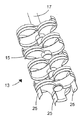
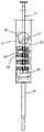
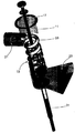
図2〜5は、本発明に使用できる撹拌装置のタイプの一例を示している。図2に示したように、撹拌手段は、ここに引用するシー・エフ・ディ・ヴォー(C.F.De Voe)の米国特許第2569459号明細書に開示された一般タイプのものであって差し支えない。もちろん、他の撹拌手段の設計を、本発明を実施するのに用いても差し支えない。ポンプ作用を生じるには一般に、許容できないほど高いレベルの剪断応力を必要とするので、撹拌手段はガラスを撹拌チャンバに著しくはポンプ作用で通さないことが好ましい。撹拌手段および撹拌チャンバの壁は、白金、白金合金もしくは分散強化した白金または白金合金(例えば、ジルコニア強化白金合金)からなることが好ましい。 2-5 show an example of the type of stirrer that can be used in the present invention. As shown in FIG. 2, the agitation means can be of the general type disclosed in US Pat. No. 2,694,595 to C.F. De Voe cited herein. Of course, other agitation means designs may be used to practice the invention. Since the pumping action generally requires an unacceptably high level of shear stress, it is preferred that the stirring means does not significantly pump the glass through the stirring chamber. The walls of the stirring means and the stirring chamber are preferably made of platinum, platinum alloy or dispersion strengthened platinum or a platinum alloy (eg, zirconia reinforced platinum alloy).
図に示したように、撹拌手段13は、撹拌手段の軸17に対して実質的に平行であるが、同一直線上にはない縦軸(長さ)を持つ部材(指)25を備えていることが好ましい。使用した部材25の数は、実施例について、1から7まで変動しても差し支えなく、特定の装置に応じて、その長さは例えば、1から4インチ(約2.5cmから10cm)であって差し支えない。実際には、それぞれ約2.2インチ(約5.5cm)の作業長さを持つ3つの部材が、高さが6インチ(約15cm)の出口ポートについて、うまく動作することが分かった。比較のために、撹拌手段の羽根15の高さは2.5インチ(約6.3cm)であって差し支えない。
As shown in the figure, the stirring means 13 includes a member (finger) 25 having a vertical axis (length) that is substantially parallel to the
これらの部材は、軸17の底部より下に延在することが好ましく、撹拌手段の羽根および軸と同じ材料からなることが好ましい。部材の全ては同じ高さを持つことが好ましいが、所望であれば、異なる高さを持つ部材を用いても差し支えない。部材の周辺の幅は、撹拌手段の軸17に対する位置に応じて異なって差し支えなく、例えば、図2の撹拌手段については、軸に最も近い部材の幅は2.0インチ(約5cm)であって差し支えなく、一方で、撹拌手段の外側周囲での部材は、1.5インチ(約3.3cm)の幅を有していて差し支えない。
These members preferably extend below the bottom of the
部材25は、(1)本発明の撹拌装置に用いたより遅い回転速度(例えば、3から15rpmの回転速度)および(2)ガラスが撹拌チャンバの本体から出口ポート23に入るときに生じる流動方向の変化(例えば、90°の方向の変化)から生じることが分かった脈理レベルの増加を最小にするように働く。部材25は、これらの部材が撹拌チャンバを通過するガラスの実質的に半径方向の流動を生じないが、撹拌手段の羽根15はそのような流動を生じるという点で、羽根とは区別される。
The
図3〜5に示したように、撹拌チャンバ11は、例えば、装置の停止中に、撹拌チャンバからガラスを除去するための排液管31を備えていても差し支えない。それに加え(または代わりに)、撹拌チャンバは、図1に点線で示したような液だめ27を備えていても差し支えない。
As shown in FIGS. 3 to 5, the stirring
実際には、部材25は、出口ポート23の頂部から下方に延在するが、撹拌チャンバの底部までは到達しないことが好ましいことが分かった。特に、部材25の下端から撹拌チャンバの底部(液だめを用いた場合には液だめの頂部、すなわち、チャンバの底部は機能的に液だめの頂部である)の距離dの比が、以下の範囲にあることが好ましい:
0.2h≦d≦0.7h(例えば、d≒0.4h) (13)
ここで、hは出口ポートの高さである(図1参照)。この範囲にある場合、部材25は、撹拌チャンバの出口ポートの領域における溶融ガラスの流動パターンを効果的に切りつける(図3〜4の流動等高線33を参照のこと)。この切断作用によって、完成ガラスの脈理のレベルは、ガラス中の含有物のレベルを増加させずに減少する。
In practice, it has been found that the
0.2h ≦ d ≦ 0.7h (for example, d≈0.4h) (13)
Here, h is the height of the outlet port (see FIG. 1). When in this range,
いかようにも本発明を制限する意図なく、本発明を以下の実施例によってより詳しく説明する。 Without intending to limit the invention in any way, the invention is illustrated in more detail by the following examples.
実施例1
上述した概念の適用例として、表1は二つの撹拌装置を比較している。第1の装置は以前に用いられていた撹拌装置(例えば、羽根の直径が6インチ(約15cm)であり、ガラスの粘度が3000ポアズであり、撹拌手段の回転速度が30rpmである撹拌装置)を表し、第2の装置は本発明により設計した撹拌装置(例えば、直径が10インチ(約25cm)であり、ガラスの粘度が1000ポアズ(例えば、約80℃だけ溶融ガラスの温度を上昇させることにより達成される)であり、撹拌手段の回転速度が6.3rpmである撹拌装置)を表す。
Example 1
As an application of the concept described above, Table 1 compares two agitation devices. The first device is a previously used stirring device (for example, a stirring device having a blade diameter of 6 inches (about 15 cm), a glass viscosity of 3000 poise, and a stirring means rotating speed of 30 rpm). And the second device is a stirrer designed according to the present invention (e.g., 10 inches in diameter (about 25 cm) with a glass viscosity of 1000 poise (e.g., raising the temperature of the molten glass by about 80 ° C). And a stirring device in which the rotation speed of the stirring means is 6.3 rpm).
この表から分かるように、撹拌手段にかかる剪断応力は、撹拌手段の直径を6インチ(約15cm)から10インチ(約25cm)まで増加させ、撹拌されるガラスの粘度を3000ポアズから1000ポアズまで減少させることにより、ほぼ一桁減少させることができる。これらの変更により、撹拌手段の速度を四分の一に遅くできる。有用な副産物は、軸にかかるねじれ応力も約25%減少することであり、このことは、撹拌手段の寿命を長くするのに役立つ。 As can be seen from this table, the shear stress on the stirring means increases the diameter of the stirring means from 6 inches (about 15 cm) to 10 inches (about 25 cm), and the viscosity of the stirred glass from 3000 poise to 1000 poise. By reducing, it can be reduced by almost an order of magnitude. With these changes, the speed of the stirring means can be reduced to a quarter. A useful by-product is that the torsional stress on the shaft is also reduced by about 25%, which helps to extend the life of the stirring means.
実施例2
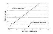
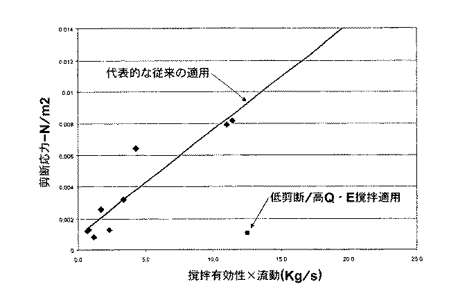
図6および7は、従来の撹拌(ダイヤモンドのデータ点)と本発明により行った撹拌(正方形のデータ点)との比較を示している。これらのデータは、実際の製造装置を用いて得た。全ての場合、撹拌は、実質的に垂直に向けられた撹拌チャンバおよび実質的に垂直に向けられた軸を持つ実質的にポンピング作用のない撹拌手段を用いて行った。
Example 2
Figures 6 and 7 show a comparison between conventional agitation (diamond data points) and agitation performed according to the present invention (square data points). These data were obtained using actual manufacturing equipment. In all cases, agitation was performed using a substantially vertically oriented agitation chamber and a substantially non-pumping agitation means having a substantially vertically oriented axis.
従来のデータへのフィットである図6の直線は、本発明の前に、高いQ・Eの積は、高レベルの剪断応力の使用によってのみ達成できたことを示している。これとは反対に、低レベルの剪断応力は、低いQ・Eの積によってのみ達成された。対照的に、本発明の概念による撹拌は、低剪断応力と高Q・E積を同時に達成する。LCDガラスの製造における低剪断応力の重要性が図7に示されている。ここに示したように、本発明によれば、含有物(特に、10マイクロメートルより大きいサイズを持つ貴金属の含有物)のレベルは剪断応力の線形関数であり、一方で、剪断応力は方程式(2)を用いて計算される。図7の直線のフィットが示しているように、剪断応力が1.1×10⁻³N/m2未満のときには、含有物/キログラム値がゼロに到達する。図7のデータは、分解能が10マイクロメートルより大きいサイズを持つ含有物に限られている装置を用いて得た。本発明により10マイクロメートル未満のサイズの含有物のレベルが減少すると考えられる。 The straight line of FIG. 6, which is a fit to conventional data, shows that prior to the present invention, a high Q · E product could only be achieved by the use of high levels of shear stress. In contrast, low levels of shear stress were achieved only with low Q · E products. In contrast, agitation according to the inventive concept simultaneously achieves low shear stress and high Q · E product. The importance of low shear stress in the manufacture of LCD glass is illustrated in FIG. As shown here, according to the present invention, the level of inclusions (especially the inclusions of noble metals having a size greater than 10 micrometers) is a linear function of shear stress, while the shear stress is expressed by the equation ( 2). As the linear fit in FIG. 7 shows, the inclusion / kilogram value reaches zero when the shear stress is less than 1.1 × 10 −3 N / m 2 . The data in FIG. 7 was obtained using a device whose resolution is limited to inclusions having a size greater than 10 micrometers. It is believed that the present invention reduces the level of inclusions having a size of less than 10 micrometers.
本発明の特定の実施の形態を記載し、説明してきたが、特許請求の範囲により定義される本発明の精神および範囲から逸脱せずに、変更を行えることが理解されよう。
11 撹拌チャンバ
13 撹拌手段
15 撹拌手段の羽根
17 撹拌手段の軸
19 撹拌チャンバの壁
21 入口ポート
23 出口ポート
25 撹拌部材(指)
27 随意的な液だめ
29 モータ
31 排液管
33 流動矢印、流動等高線、および流導管を示す流動方向表示
DESCRIPTION OF
27
Claims (3)
(a) 壁を備えた円筒形状の実質的に垂直に向けられた撹拌チャンバ、および
(b) 実質的に垂直に向けられた軸と、該軸から外側に前記撹拌チャンバの壁に向かって延在する複数の羽根とを備えた、前記撹拌チャンバ内の撹拌手段、
を備え、
前記撹拌チャンバが、該撹拌チャンバから流出するガラスが流動方向の変化を経るような側部出口ポートを備え、前記撹拌手段が、流動方向が変化する領域においてガラスを撹拌するための少なくとも一つの部材を備え、該少なくとも一つの部材が、前記撹拌手段の軸と実質的に平行であるが、同一直線上にはないことを特徴とする装置。 An apparatus for making molten glass uniform,
(A) a cylindrically shaped substantially vertically oriented stirring chamber with walls; and (b) a substantially vertically oriented shaft and extending outwardly from the shaft toward the wall of the stirring chamber. Agitation means in the agitation chamber comprising a plurality of existing vanes;
With
The agitation chamber comprises a side outlet port through which the glass flowing out of the agitation chamber undergoes a change in flow direction, and the agitation means is at least one member for agitating the glass in a region where the flow direction changes. And wherein the at least one member is substantially parallel to the axis of the stirring means but is not collinear.
(ii) 前記側部出口ポートが、前記底部の領域にあり、垂直高さhを持ち、
(iii) 前記少なくとも一つの部材が、前記撹拌チャンバの底部から距離dだけ離れた下端を有し、
ここで、dが以下の関係:
0.2h≦d≦0.7h、
にあることを特徴とする請求項1記載の装置。 (I) the stirring chamber has a bottom;
(Ii) the side outlet port is in the region of the bottom and has a vertical height h;
(Iii) the at least one member has a lower end separated from the bottom of the stirring chamber by a distance d;
Where d is the following relationship:
0.2h ≦ d ≦ 0.7h,
2. The apparatus of claim 1 wherein:
Applications Claiming Priority (2)
| Application Number | Priority Date | Filing Date | Title |
|---|---|---|---|
| US33528601P | 2001-11-30 | 2001-11-30 | |
| US60/335,286 | 2001-11-30 |
Related Parent Applications (1)
| Application Number | Title | Priority Date | Filing Date |
|---|---|---|---|
| JP2003549251A Division JP4433382B2 (en) | 2001-11-30 | 2002-10-15 | Method and apparatus for making molten glass uniform by stirring |
Publications (2)
| Publication Number | Publication Date |
|---|---|
| JP2010042994A true JP2010042994A (en) | 2010-02-25 |
| JP5123272B2 JP5123272B2 (en) | 2013-01-23 |
Family
ID=23311106
Family Applications (2)
| Application Number | Title | Priority Date | Filing Date |
|---|---|---|---|
| JP2003549251A Expired - Fee Related JP4433382B2 (en) | 2001-11-30 | 2002-10-15 | Method and apparatus for making molten glass uniform by stirring |
| JP2009239112A Expired - Fee Related JP5123272B2 (en) | 2001-11-30 | 2009-10-16 | Equipment that makes molten glass uniform by stirring |
Family Applications Before (1)
| Application Number | Title | Priority Date | Filing Date |
|---|---|---|---|
| JP2003549251A Expired - Fee Related JP4433382B2 (en) | 2001-11-30 | 2002-10-15 | Method and apparatus for making molten glass uniform by stirring |
Country Status (6)
| Country | Link |
|---|---|
| US (1) | US7127919B2 (en) |
| JP (2) | JP4433382B2 (en) |
| KR (1) | KR100878605B1 (en) |
| CN (1) | CN100341806C (en) |
| TW (1) | TWI233431B (en) |
| WO (1) | WO2003048054A1 (en) |
Cited By (1)
| Publication number | Priority date | Publication date | Assignee | Title |
|---|---|---|---|---|
| KR101798719B1 (en) | 2014-11-24 | 2017-11-16 | 주식회사 엘지화학 | Stirrer for manufacturing LCD glass, manufacturing method thereof and LCD glass |
Families Citing this family (42)
| Publication number | Priority date | Publication date | Assignee | Title |
|---|---|---|---|---|
| JP2007521218A (en) * | 2003-11-28 | 2007-08-02 | コーニング インコーポレイテッド | Manufacturing method of glass panel |
| DE102004032795B4 (en) * | 2004-07-07 | 2007-06-21 | Schott Ag | Stirring device for stirring and homogenizing glass melts |
| US20060042318A1 (en) * | 2004-08-31 | 2006-03-02 | Burdette Steven R | Method and apparatus for homogenizing a glass melt |
| ATE468912T1 (en) * | 2005-04-18 | 2010-06-15 | Gea Pharma Systems Nv | DEVICE FOR CONTINUOUS GRANULATING AND METHOD FOR CONTINUOUS GRANULATING POWDER MATERIAL |
| CN101356123B (en) * | 2006-01-05 | 2011-12-14 | 日本电气硝子株式会社 | Molten glass supply apparatus and method for producing glass molded article |
| CN102173560A (en) * | 2006-01-05 | 2011-09-07 | 日本电气硝子株式会社 | Molten glass supply apparatus and process for producing glass formed article |
| JP2007269509A (en) * | 2006-03-30 | 2007-10-18 | Ohara Inc | Melting apparatus |
| US7578144B2 (en) * | 2006-07-13 | 2009-08-25 | Corning Incorporated | Method for minimizing refractory metal inclusions in a glass stirring operation |
| CN1931754B (en) * | 2006-09-30 | 2011-05-11 | 河南安彩高科股份有限公司 | Apparatus and method for raising glass melt stirring efficiency |
| DE102006060972B4 (en) * | 2006-12-20 | 2012-12-06 | Schott Ag | Method and apparatus for homogenizing a molten glass, and use |
| US8256951B2 (en) * | 2006-12-21 | 2012-09-04 | Corning Incorporated | Stirrers for minimizing erosion of refractory metal vessels in a glass making system |
| DE102007008102B4 (en) * | 2007-02-19 | 2020-12-03 | Umicore Ag & Co. Kg | Device for use in the glass industry and processes |
| DE102007011505A1 (en) | 2007-02-26 | 2008-08-28 | Eglass Machinery & Parts Gmbh | Device homogenizing viscous materials, dispersing striation and streaks, employs stirrer body with vanes designed and arranged to increase stirrer efficiency |
| DE102007035203B4 (en) * | 2007-07-25 | 2012-12-06 | Schott Ag | Method and apparatus for homogenizing a molten glass, and use |
| US20090078003A1 (en) * | 2007-09-24 | 2009-03-26 | Glen Bennett Cook | Free-surface mixing method and apparatus therefor |
| US20090217708A1 (en) * | 2008-02-29 | 2009-09-03 | Gilbert Deangelis | Methods and apparatus for reducing platinum-group defects in sheet glass |
| DE102008017045B9 (en) * | 2008-04-03 | 2012-07-05 | Umicore Ag & Co. Kg | Stirring system and method for homogenizing glass melts |
| US20100080078A1 (en) * | 2008-09-29 | 2010-04-01 | Martin Herbert Goller | Method and apparatus for homogenizing a glass melt |
| JP2010100462A (en) * | 2008-10-22 | 2010-05-06 | Avanstrate Inc | Agitating blade and agitating device for molten glass |
| DE102009000785B4 (en) * | 2009-02-11 | 2015-04-02 | Schott Ag | Method and device for producing glass |
| WO2010098328A1 (en) * | 2009-02-27 | 2010-09-02 | 旭硝子株式会社 | Device for stirring molten glass |
| US8117868B2 (en) * | 2009-07-27 | 2012-02-21 | Corning Incorporated | Apparatus and methods for making glass |
| US20120180529A1 (en) * | 2009-08-21 | 2012-07-19 | Rudolf Singer | Mixing Apparatus |
| TWI471280B (en) * | 2009-11-30 | 2015-02-01 | Corning Inc | Method and apparatus for reducing condensate related defects in a glass manufacturing process |
| US8650910B2 (en) | 2010-08-23 | 2014-02-18 | Corning Incorporated | Apparatus for homogenizing a glass melt |
| JP5580889B2 (en) | 2010-11-01 | 2014-08-27 | AvanStrate株式会社 | Manufacturing method of glass substrate and stirring device |
| WO2012093183A1 (en) * | 2011-01-05 | 2012-07-12 | Luis Grijalba Goicoechea | Method and unit for melting glass at low temperatures |
| US9061928B2 (en) | 2011-02-28 | 2015-06-23 | Corning Incorporated | Ultrasonic transducer assembly for applying ultrasonic acoustic energy to a glass melt |
| EP2626334B1 (en) * | 2011-11-18 | 2019-01-16 | Avanstrate Inc. | Method for producing glass and stirring device |
| CN103382078B (en) * | 2012-05-01 | 2016-12-28 | 安瀚视特控股株式会社 | The manufacture method of glass substrate, the manufacture device of glass substrate and agitating device |
| JP2013249247A (en) * | 2012-05-01 | 2013-12-12 | Avanstrate Inc | Method for producing glass substrate, device for producing glass substrate, and agitating device |
| JP2015171957A (en) * | 2012-07-17 | 2015-10-01 | 旭硝子株式会社 | Production method of glass sheet, and glass sheet |
| JP2014047102A (en) * | 2012-08-31 | 2014-03-17 | Avanstrate Inc | Manufacturing method for glass substrate, manufacturing device for glass substrate, and agitation tank |
| DE102014211346A1 (en) * | 2014-06-13 | 2015-12-17 | Schott Ag | Method and device for producing a glass article from a glass melt |
| JP6458691B2 (en) * | 2014-10-14 | 2019-01-30 | Agc株式会社 | Molten glass stirring device, plate glass manufacturing device, molten glass stirring method, and plate glass manufacturing method |
| CN106277717B (en) * | 2016-08-15 | 2019-04-26 | 芜湖东旭光电科技有限公司 | Glass liquid stirring stick |
| EP3504166B1 (en) | 2016-08-24 | 2021-05-05 | Corning Incorporated | Glass manufacturing methods |
| WO2018116530A1 (en) * | 2016-12-22 | 2018-06-28 | 日本電気硝子株式会社 | Stirrer and method for manufacturing glass plate |
| KR102415723B1 (en) | 2017-11-20 | 2022-07-04 | 코닝 인코포레이티드 | Molten material stirring system and Method for stirring the material |
| CN110790477A (en) * | 2019-12-18 | 2020-02-14 | 成都光明光电股份有限公司 | Molten glass stirring device and molten glass quality improvement method |
| DE102020103328A1 (en) | 2020-02-10 | 2021-08-12 | Schott Ag | Method and device for homogenizing viscous liquids |
| CN116943464A (en) * | 2023-08-03 | 2023-10-27 | 广州芙莉莱化妆品有限公司 | Cosmetic stirring parameter conversion method |
Citations (3)
| Publication number | Priority date | Publication date | Assignee | Title |
|---|---|---|---|---|
| JPS6136123A (en) * | 1984-07-26 | 1986-02-20 | Toshiba Corp | Glass-stirring structure |
| JPS638226A (en) * | 1986-06-24 | 1988-01-14 | Hoya Corp | Stirrer for molten glass |
| JPH05229831A (en) * | 1992-02-20 | 1993-09-07 | Asahi Glass Co Ltd | Method for homogenizing molten material and apparatus therefor |
Family Cites Families (26)
| Publication number | Priority date | Publication date | Assignee | Title |
|---|---|---|---|---|
| US2569459A (en) * | 1945-08-09 | 1951-10-02 | Corning Glass Works | Method and apparatus for stirring glass |
| US2570078A (en) | 1950-02-09 | 1951-10-02 | Corning Glass Works | Stirrer and feeder |
| US2750161A (en) * | 1952-08-05 | 1956-06-12 | Pittsburgh Plate Glass Co | Method for stirring glass |
| US2831664A (en) * | 1953-10-30 | 1958-04-22 | Corning Glass Works | Glass stirring |
| US3352659A (en) | 1964-06-15 | 1967-11-14 | Corning Glass Works | Apparatus for blending glass |
| US4325724A (en) * | 1974-11-25 | 1982-04-20 | Owens-Corning Fiberglas Corporation | Method for making glass |
| US3951635A (en) * | 1974-11-29 | 1976-04-20 | Owens-Illinois, Inc. | Method for rapidly melting and refining glass |
| US4493557A (en) * | 1982-11-01 | 1985-01-15 | Corning Glass Works | Mixing apparatus |
| US5198156A (en) * | 1986-02-17 | 1993-03-30 | Imperial Chemical Industries Plc | Agitators |
| US4744809A (en) * | 1987-01-02 | 1988-05-17 | Ppg Industries, Inc. | Method and apparatus for homogenizing flat glass |
| EP0441505A1 (en) * | 1990-02-05 | 1991-08-14 | Imperial Chemical Industries Plc | Agitators |
| EP0470493B1 (en) * | 1990-08-07 | 1996-09-25 | Shinko Pantec Co., Ltd. | Mixing apparatus |
| US5120342A (en) * | 1991-03-07 | 1992-06-09 | Glasstech, Inc. | High shear mixer and glass melting apparatus |
| JP3116400B2 (en) * | 1991-03-18 | 2000-12-11 | 日本板硝子株式会社 | Glass base homogenization method |
| US5319669A (en) * | 1992-01-22 | 1994-06-07 | Stir-Melter, Inc. | Hazardous waste melter |
| JPH05226831A (en) * | 1992-02-18 | 1993-09-03 | Sumitomo Electric Ind Ltd | Circuit board |
| DE4440704C2 (en) * | 1994-11-15 | 1997-02-13 | Ilmenau Tech Glas | Stirrer for molten glass |
| CN1163602A (en) * | 1994-11-15 | 1997-10-29 | 伊尔默瑙玻璃技术有限公司 | Method and device for homogenizing glass melts |
| GB2306467A (en) * | 1995-10-28 | 1997-05-07 | Pilkington Plc | Method and apparatus for making glass |
| KR100444628B1 (en) * | 1995-11-21 | 2004-11-03 | 아사히 가라스 가부시키가이샤 | Method and apparatus for refining molten glass |
| JP2001072426A (en) * | 1999-08-30 | 2001-03-21 | Central Glass Co Ltd | Stirring apparatus for molten glass |
| US6270248B1 (en) * | 1999-10-07 | 2001-08-07 | Asahi Glass Company Ltd. | Mixing apparatus for a molten substance of high temperature |
| AT4238U1 (en) * | 2000-05-02 | 2001-04-25 | Plansee Ag | MIXER FOR GLASS MELTING |
| WO2002018282A2 (en) * | 2000-08-30 | 2002-03-07 | Richard Pitbladdo | Process and pump for homogenizing molten glass |
| US6508583B1 (en) * | 2000-11-28 | 2003-01-21 | E. I. Du Pont De Nemours And Company | Agitated vessel for producing a suspension of solids |
| US7172337B2 (en) * | 2003-07-08 | 2007-02-06 | Philadelphia Mixing Solutions, A Division Of Philadelphia Gear Corporation | Low shear impeller |
-
2002
- 2002-10-15 WO PCT/US2002/032862 patent/WO2003048054A1/en active Application Filing
- 2002-10-15 JP JP2003549251A patent/JP4433382B2/en not_active Expired - Fee Related
- 2002-10-15 KR KR1020047008216A patent/KR100878605B1/en active IP Right Grant
- 2002-10-15 CN CNB02823863XA patent/CN100341806C/en not_active Expired - Fee Related
- 2002-11-22 US US10/302,661 patent/US7127919B2/en not_active Expired - Lifetime
- 2002-12-10 TW TW091136058A patent/TWI233431B/en not_active IP Right Cessation
-
2009
- 2009-10-16 JP JP2009239112A patent/JP5123272B2/en not_active Expired - Fee Related
Patent Citations (3)
| Publication number | Priority date | Publication date | Assignee | Title |
|---|---|---|---|---|
| JPS6136123A (en) * | 1984-07-26 | 1986-02-20 | Toshiba Corp | Glass-stirring structure |
| JPS638226A (en) * | 1986-06-24 | 1988-01-14 | Hoya Corp | Stirrer for molten glass |
| JPH05229831A (en) * | 1992-02-20 | 1993-09-07 | Asahi Glass Co Ltd | Method for homogenizing molten material and apparatus therefor |
Cited By (1)
| Publication number | Priority date | Publication date | Assignee | Title |
|---|---|---|---|---|
| KR101798719B1 (en) | 2014-11-24 | 2017-11-16 | 주식회사 엘지화학 | Stirrer for manufacturing LCD glass, manufacturing method thereof and LCD glass |
Also Published As
| Publication number | Publication date |
|---|---|
| KR20050036902A (en) | 2005-04-20 |
| CN100341806C (en) | 2007-10-10 |
| TW200409737A (en) | 2004-06-16 |
| CN1596225A (en) | 2005-03-16 |
| JP5123272B2 (en) | 2013-01-23 |
| US20030101750A1 (en) | 2003-06-05 |
| JP2005511462A (en) | 2005-04-28 |
| US7127919B2 (en) | 2006-10-31 |
| KR100878605B1 (en) | 2009-01-15 |
| TWI233431B (en) | 2005-06-01 |
| JP4433382B2 (en) | 2010-03-17 |
| WO2003048054A1 (en) | 2003-06-12 |
Similar Documents
| Publication | Publication Date | Title |
|---|---|---|
| JP5123272B2 (en) | Equipment that makes molten glass uniform by stirring | |
| JP5757946B2 (en) | Mixing equipment | |
| JP5588675B2 (en) | How to minimize refractory metal foreign objects in glass stirring operations | |
| JP2009542577A5 (en) | ||
| JP5246568B1 (en) | Glass production method and stirring device | |
| JP2010100462A (en) | Agitating blade and agitating device for molten glass | |
| KR101761457B1 (en) | Apparatus for making a glass article and methods | |
| CN105246843A (en) | Process and apparatus for refining molten glass | |
| JP2001072426A (en) | Stirring apparatus for molten glass | |
| JP2006247458A (en) | Apparatus for producing dispersion and method for producing alkali metal dispersion with using the same | |
| JP4561017B2 (en) | Stirring apparatus for molten glass and glass manufacturing method | |
| JP3947087B2 (en) | Stirrer for glass production | |
| JP5741154B2 (en) | Glass melting furnace and molten glass outflow method | |
| SU958332A1 (en) | Apparatus for homogenizing glass mass | |
| JP2005119914A (en) | Stirrer for stirring glass | |
| KR20030022574A (en) | Apparatus for measuring torque simulation stirrer | |
| JPH11300189A (en) | Stirring apparatus for high-temperature melt |
Legal Events
| Date | Code | Title | Description |
|---|---|---|---|
| A131 | Notification of reasons for refusal |
Free format text: JAPANESE INTERMEDIATE CODE: A131 Effective date: 20120612 |
|
| A521 | Written amendment |
Free format text: JAPANESE INTERMEDIATE CODE: A523 Effective date: 20120911 |
|
| TRDD | Decision of grant or rejection written | ||
| A01 | Written decision to grant a patent or to grant a registration (utility model) |
Free format text: JAPANESE INTERMEDIATE CODE: A01 Effective date: 20121002 |
|
| A01 | Written decision to grant a patent or to grant a registration (utility model) |
Free format text: JAPANESE INTERMEDIATE CODE: A01 |
|
| A61 | First payment of annual fees (during grant procedure) |
Free format text: JAPANESE INTERMEDIATE CODE: A61 Effective date: 20121025 |
|
| FPAY | Renewal fee payment (event date is renewal date of database) |
Free format text: PAYMENT UNTIL: 20151102 Year of fee payment: 3 |
|
| R150 | Certificate of patent or registration of utility model |
Ref document number: 5123272 Country of ref document: JP Free format text: JAPANESE INTERMEDIATE CODE: R150 Free format text: JAPANESE INTERMEDIATE CODE: R150 |
|
| R250 | Receipt of annual fees |
Free format text: JAPANESE INTERMEDIATE CODE: R250 |
|
| R250 | Receipt of annual fees |
Free format text: JAPANESE INTERMEDIATE CODE: R250 |
|
| R250 | Receipt of annual fees |
Free format text: JAPANESE INTERMEDIATE CODE: R250 |
|
| R250 | Receipt of annual fees |
Free format text: JAPANESE INTERMEDIATE CODE: R250 |
|
| R250 | Receipt of annual fees |
Free format text: JAPANESE INTERMEDIATE CODE: R250 |
|
| LAPS | Cancellation because of no payment of annual fees |