JP2010042662A - Method for manufacturing hollow shaft having at least one integrated flange made of fiber composite material - Google Patents
Method for manufacturing hollow shaft having at least one integrated flange made of fiber composite material Download PDFInfo
- Publication number
- JP2010042662A JP2010042662A JP2009141087A JP2009141087A JP2010042662A JP 2010042662 A JP2010042662 A JP 2010042662A JP 2009141087 A JP2009141087 A JP 2009141087A JP 2009141087 A JP2009141087 A JP 2009141087A JP 2010042662 A JP2010042662 A JP 2010042662A
- Authority
- JP
- Japan
- Prior art keywords
- flange
- expansion ring
- shaft
- ring
- hollow shaft
- Prior art date
- Legal status (The legal status is an assumption and is not a legal conclusion. Google has not performed a legal analysis and makes no representation as to the accuracy of the status listed.)
- Granted
Links
- 239000000835 fiber Substances 0.000 title claims abstract description 60
- 239000002131 composite material Substances 0.000 title claims abstract description 27
- 238000000034 method Methods 0.000 title claims abstract description 27
- 238000004519 manufacturing process Methods 0.000 title claims abstract description 19
- 239000002657 fibrous material Substances 0.000 claims abstract description 51
- 238000004804 winding Methods 0.000 claims description 54
- 230000002093 peripheral effect Effects 0.000 claims description 18
- 239000000463 material Substances 0.000 claims description 7
- 230000008021 deposition Effects 0.000 claims description 5
- 238000006073 displacement reaction Methods 0.000 claims 1
- 230000000284 resting effect Effects 0.000 claims 1
- 230000000087 stabilizing effect Effects 0.000 claims 1
- 230000009286 beneficial effect Effects 0.000 description 6
- 238000010586 diagram Methods 0.000 description 6
- 230000015572 biosynthetic process Effects 0.000 description 3
- 239000000306 component Substances 0.000 description 2
- 239000008358 core component Substances 0.000 description 2
- 229920000049 Carbon (fiber) Polymers 0.000 description 1
- 230000006978 adaptation Effects 0.000 description 1
- 230000002411 adverse Effects 0.000 description 1
- 230000004323 axial length Effects 0.000 description 1
- 239000004917 carbon fiber Substances 0.000 description 1
- 230000008878 coupling Effects 0.000 description 1
- 238000010168 coupling process Methods 0.000 description 1
- 238000005859 coupling reaction Methods 0.000 description 1
- 230000000694 effects Effects 0.000 description 1
- 239000000806 elastomer Substances 0.000 description 1
- 239000013536 elastomeric material Substances 0.000 description 1
- 238000005516 engineering process Methods 0.000 description 1
- 239000004744 fabric Substances 0.000 description 1
- 239000003365 glass fiber Substances 0.000 description 1
- 230000012447 hatching Effects 0.000 description 1
- 239000011159 matrix material Substances 0.000 description 1
- 239000002184 metal Substances 0.000 description 1
- 238000000465 moulding Methods 0.000 description 1
- 238000005457 optimization Methods 0.000 description 1
- 229920003051 synthetic elastomer Polymers 0.000 description 1
- 229920003002 synthetic resin Polymers 0.000 description 1
- 239000000057 synthetic resin Substances 0.000 description 1
- 239000004753 textile Substances 0.000 description 1
- 229920001169 thermoplastic Polymers 0.000 description 1
- 239000004416 thermosoftening plastic Substances 0.000 description 1
Images


Classifications
-
- B—PERFORMING OPERATIONS; TRANSPORTING
- B29—WORKING OF PLASTICS; WORKING OF SUBSTANCES IN A PLASTIC STATE IN GENERAL
- B29C—SHAPING OR JOINING OF PLASTICS; SHAPING OF MATERIAL IN A PLASTIC STATE, NOT OTHERWISE PROVIDED FOR; AFTER-TREATMENT OF THE SHAPED PRODUCTS, e.g. REPAIRING
- B29C53/00—Shaping by bending, folding, twisting, straightening or flattening; Apparatus therefor
- B29C53/56—Winding and joining, e.g. winding spirally
-
- F—MECHANICAL ENGINEERING; LIGHTING; HEATING; WEAPONS; BLASTING
- F16—ENGINEERING ELEMENTS AND UNITS; GENERAL MEASURES FOR PRODUCING AND MAINTAINING EFFECTIVE FUNCTIONING OF MACHINES OR INSTALLATIONS; THERMAL INSULATION IN GENERAL
- F16C—SHAFTS; FLEXIBLE SHAFTS; ELEMENTS OR CRANKSHAFT MECHANISMS; ROTARY BODIES OTHER THAN GEARING ELEMENTS; BEARINGS
- F16C3/00—Shafts; Axles; Cranks; Eccentrics
- F16C3/02—Shafts; Axles
- F16C3/026—Shafts made of fibre reinforced resin
-
- B—PERFORMING OPERATIONS; TRANSPORTING
- B29—WORKING OF PLASTICS; WORKING OF SUBSTANCES IN A PLASTIC STATE IN GENERAL
- B29C—SHAPING OR JOINING OF PLASTICS; SHAPING OF MATERIAL IN A PLASTIC STATE, NOT OTHERWISE PROVIDED FOR; AFTER-TREATMENT OF THE SHAPED PRODUCTS, e.g. REPAIRING
- B29C53/00—Shaping by bending, folding, twisting, straightening or flattening; Apparatus therefor
- B29C53/56—Winding and joining, e.g. winding spirally
- B29C53/58—Winding and joining, e.g. winding spirally helically
- B29C53/583—Winding and joining, e.g. winding spirally helically for making tubular articles with particular features
- B29C53/585—Winding and joining, e.g. winding spirally helically for making tubular articles with particular features the cross-section varying along their axis, e.g. tapered, with ribs, or threads, with socket-ends
-
- B—PERFORMING OPERATIONS; TRANSPORTING
- B29—WORKING OF PLASTICS; WORKING OF SUBSTANCES IN A PLASTIC STATE IN GENERAL
- B29C—SHAPING OR JOINING OF PLASTICS; SHAPING OF MATERIAL IN A PLASTIC STATE, NOT OTHERWISE PROVIDED FOR; AFTER-TREATMENT OF THE SHAPED PRODUCTS, e.g. REPAIRING
- B29C53/00—Shaping by bending, folding, twisting, straightening or flattening; Apparatus therefor
- B29C53/56—Winding and joining, e.g. winding spirally
- B29C53/58—Winding and joining, e.g. winding spirally helically
- B29C53/60—Winding and joining, e.g. winding spirally helically using internal forming surfaces, e.g. mandrels
-
- B—PERFORMING OPERATIONS; TRANSPORTING
- B29—WORKING OF PLASTICS; WORKING OF SUBSTANCES IN A PLASTIC STATE IN GENERAL
- B29C—SHAPING OR JOINING OF PLASTICS; SHAPING OF MATERIAL IN A PLASTIC STATE, NOT OTHERWISE PROVIDED FOR; AFTER-TREATMENT OF THE SHAPED PRODUCTS, e.g. REPAIRING
- B29C53/00—Shaping by bending, folding, twisting, straightening or flattening; Apparatus therefor
- B29C53/80—Component parts, details or accessories; Auxiliary operations
- B29C53/82—Cores or mandrels
-
- B—PERFORMING OPERATIONS; TRANSPORTING
- B29—WORKING OF PLASTICS; WORKING OF SUBSTANCES IN A PLASTIC STATE IN GENERAL
- B29C—SHAPING OR JOINING OF PLASTICS; SHAPING OF MATERIAL IN A PLASTIC STATE, NOT OTHERWISE PROVIDED FOR; AFTER-TREATMENT OF THE SHAPED PRODUCTS, e.g. REPAIRING
- B29C57/00—Shaping of tube ends, e.g. flanging, belling or closing; Apparatus therefor, e.g. collapsible mandrels
-
- F—MECHANICAL ENGINEERING; LIGHTING; HEATING; WEAPONS; BLASTING
- F16—ENGINEERING ELEMENTS AND UNITS; GENERAL MEASURES FOR PRODUCING AND MAINTAINING EFFECTIVE FUNCTIONING OF MACHINES OR INSTALLATIONS; THERMAL INSULATION IN GENERAL
- F16D—COUPLINGS FOR TRANSMITTING ROTATION; CLUTCHES; BRAKES
- F16D1/00—Couplings for rigidly connecting two coaxial shafts or other movable machine elements
- F16D1/06—Couplings for rigidly connecting two coaxial shafts or other movable machine elements for attachment of a member on a shaft or on a shaft-end
- F16D1/076—Couplings for rigidly connecting two coaxial shafts or other movable machine elements for attachment of a member on a shaft or on a shaft-end by clamping together two faces perpendicular to the axis of rotation, e.g. with bolted flanges
-
- B—PERFORMING OPERATIONS; TRANSPORTING
- B29—WORKING OF PLASTICS; WORKING OF SUBSTANCES IN A PLASTIC STATE IN GENERAL
- B29L—INDEXING SCHEME ASSOCIATED WITH SUBCLASS B29C, RELATING TO PARTICULAR ARTICLES
- B29L2031/00—Other particular articles
- B29L2031/748—Machines or parts thereof not otherwise provided for
- B29L2031/75—Shafts
-
- F—MECHANICAL ENGINEERING; LIGHTING; HEATING; WEAPONS; BLASTING
- F16—ENGINEERING ELEMENTS AND UNITS; GENERAL MEASURES FOR PRODUCING AND MAINTAINING EFFECTIVE FUNCTIONING OF MACHINES OR INSTALLATIONS; THERMAL INSULATION IN GENERAL
- F16D—COUPLINGS FOR TRANSMITTING ROTATION; CLUTCHES; BRAKES
- F16D2250/00—Manufacturing; Assembly
-
- Y—GENERAL TAGGING OF NEW TECHNOLOGICAL DEVELOPMENTS; GENERAL TAGGING OF CROSS-SECTIONAL TECHNOLOGIES SPANNING OVER SEVERAL SECTIONS OF THE IPC; TECHNICAL SUBJECTS COVERED BY FORMER USPC CROSS-REFERENCE ART COLLECTIONS [XRACs] AND DIGESTS
- Y10—TECHNICAL SUBJECTS COVERED BY FORMER USPC
- Y10T—TECHNICAL SUBJECTS COVERED BY FORMER US CLASSIFICATION
- Y10T29/00—Metal working
- Y10T29/49—Method of mechanical manufacture
- Y10T29/49801—Shaping fiber or fibered material
-
- Y—GENERAL TAGGING OF NEW TECHNOLOGICAL DEVELOPMENTS; GENERAL TAGGING OF CROSS-SECTIONAL TECHNOLOGIES SPANNING OVER SEVERAL SECTIONS OF THE IPC; TECHNICAL SUBJECTS COVERED BY FORMER USPC CROSS-REFERENCE ART COLLECTIONS [XRACs] AND DIGESTS
- Y10—TECHNICAL SUBJECTS COVERED BY FORMER USPC
- Y10T—TECHNICAL SUBJECTS COVERED BY FORMER US CLASSIFICATION
- Y10T29/00—Metal working
- Y10T29/53—Means to assemble or disassemble
- Y10T29/53526—Running-length work
- Y10T29/5353—Assembled on core
-
- Y—GENERAL TAGGING OF NEW TECHNOLOGICAL DEVELOPMENTS; GENERAL TAGGING OF CROSS-SECTIONAL TECHNOLOGIES SPANNING OVER SEVERAL SECTIONS OF THE IPC; TECHNICAL SUBJECTS COVERED BY FORMER USPC CROSS-REFERENCE ART COLLECTIONS [XRACs] AND DIGESTS
- Y10—TECHNICAL SUBJECTS COVERED BY FORMER USPC
- Y10T—TECHNICAL SUBJECTS COVERED BY FORMER US CLASSIFICATION
- Y10T29/00—Metal working
- Y10T29/53—Means to assemble or disassemble
- Y10T29/53535—Means to assemble or disassemble including means to vibrate work
Landscapes
- Engineering & Computer Science (AREA)
- Mechanical Engineering (AREA)
- General Engineering & Computer Science (AREA)
- Ocean & Marine Engineering (AREA)
- Moulding By Coating Moulds (AREA)
- Shafts, Cranks, Connecting Bars, And Related Bearings (AREA)
Abstract
Description
本発明は、繊維材料の複数の交差式の巻回部がコアに堆積され、繊維複合材製の少なくとも1つの一体的なフランジ(以下「一体フランジ」とも称する)を有する中空シャフトの製造方法に関する。さらに、本発明は、繊維複合材製の中空シャフトに関する。 The present invention relates to a method for manufacturing a hollow shaft in which a plurality of crossed windings of fiber material are deposited on a core and have at least one integral flange (hereinafter also referred to as “integral flange”) made of fiber composite material. . Furthermore, the present invention relates to a hollow shaft made of a fiber composite material.
このような繊維複合材シャフトは、例えば、独国特許文献DE102006042301A1に記載されるような補償カップリングにおいて使用される。ここでは、フランジに構成された固定開口の穴の内輪にわたって、繊維複合材シャフトへトルクが導入される。しかしながら、繊維複合材シャフトは、他の目的でも使用され得る。 Such fiber composite shafts are used, for example, in compensating couplings as described in German patent document DE102006042301A1. Here, torque is introduced into the fiber composite shaft over the inner ring of the hole of the fixed opening formed in the flange. However, the fiber composite shaft can also be used for other purposes.
欧州特許文献EP0443470A1から、繊維複合材製の一体フランジを有する中空シャフトの製造方法が知られている。この公知の方法では、シャフト部およびフランジが繊維材料から作られることによって、シャフト部の内側輪郭だけが、コアによって予め決定される。フランジを形成するために、シャフト部上を移動する狭い板の形状の拡張ディスクが設けられる。巻回部を形成する際、繊維材料は、拡張ディスク上に敷設され、拡張ディスクを越えて固定される。拡張ディスクの周辺で、さらなる固定が行われる。巻回部を敷設することによって、拡張ディスクの周辺とシャフト部との間に、ほぼ円錐形の部分が形成される。巻回部の仕上げ後、繊維材料は、成形ツールを用いてシャフト部のエリアに固定され、拡張ディスクの外側で切断される。次に、円錐部は、例えば、拡張ディスクを変位させることによって、半径方向に実質的に延出するフランジを形成するために、成形ツールに押圧される。次に、拡張ディスクが取り除かれ、支持ツールに取り替えられる。巻回部の円錐部を広げている間、繊維層が薄くなり、ひいては、繊維層の厚みが低減する。このため、成形ツールの軸受表面を適切な傾きを付けて構成することが考慮される。しかしながら、このような傾きは、フランジの少なくとも一方側が、軸受面として直接使用できないため、上述した使用目的では問題となる。最終的に、フランジの外側にのみ適用された繊維織物が、事前に成形ツールの軸受面に適用され得る。さらに、コンポーネントの製造中に拡張ディスクを変位させる必要があるため、この方法はさらに複雑になる。円錐部を成形ツールに適用するとき、繊維材料の繊維には負荷がかからないため、繊維構造は、フランジのエリアにおいて最適ではない。 From European Patent Document EP 0 443 470 A1, a method for producing a hollow shaft with an integral flange made of fiber composite is known. In this known method, only the inner contour of the shaft part is predetermined by the core by making the shaft part and the flange from fiber material. In order to form the flange, an extension disk in the form of a narrow plate moving on the shaft part is provided. When forming the winding, the fiber material is laid on the expansion disk and secured beyond the expansion disk. Further fixing takes place around the expansion disc. By laying the winding portion, a substantially conical portion is formed between the periphery of the expansion disk and the shaft portion. After finishing the winding part, the fiber material is fixed in the area of the shaft part using a forming tool and cut outside the expansion disc. The cone is then pressed against the forming tool to form a substantially extending flange, for example by displacing the expansion disc. The expansion disk is then removed and replaced with a support tool. While the conical portion of the winding portion is expanded, the fiber layer becomes thin, and as a result, the thickness of the fiber layer is reduced. For this reason, it is considered that the bearing surface of the forming tool is configured with an appropriate inclination. However, such an inclination becomes a problem for the above-mentioned purpose of use because at least one side of the flange cannot be used directly as a bearing surface. Finally, a textile fabric applied only on the outside of the flange can be applied in advance to the bearing surface of the forming tool. Furthermore, this method is further complicated by the need to displace the expansion disk during component manufacture. When applying the cone to the forming tool, the fiber structure is not optimal in the area of the flange because the fibers of the fiber material are not loaded.
独国特許文献DE19544008A1から、一体フランジを有する中空シャフトのさらなる製造方法が知られている。ここでも、フランジの壁の厚みは外向きに低減する。これらの一体フランジは、最終的に軸方向の接続が可能となる別のホルダに受け入れられる。 From German patent document DE19554408A1, a further method for producing a hollow shaft with an integral flange is known. Again, the thickness of the flange wall is reduced outward. These integral flanges are received in a separate holder that ultimately allows for an axial connection.
さらに、国際特許公報WO98/20263から、巻回された一体フランジ部を有する中空シャフトが知られており、ここでは、壁の厚みの低減は、金属製の閉鎖プレートによって半径方向に補償される。 Furthermore, a hollow shaft with a wound integral flange is known from International Patent Publication WO 98/20263, where the reduction in wall thickness is compensated radially by a metal closure plate.
このような背景を踏まえ、本発明の目的は、フランジのエリアにおいて均一かつ規定の繊維構造を簡単かつコスト効率良く製造可能であり、フランジの壁厚みの設定に関して柔軟である、繊維複合材製の少なくとも1つの一体フランジを有する中空シャフトの製造方法を提示することである。 In light of this background, the object of the present invention is to make a uniform and defined fiber structure in the area of the flange simple and cost-effective, and to be flexible in setting the flange wall thickness. A method of manufacturing a hollow shaft having at least one integral flange is presented.
この目的は、請求項1に記載の方法により達成される。繊維複合材製の少なくとも1つの一体フランジを有する中空シャフトを製造するための本発明による方法の場合、繊維材料の複数の交差式の巻回部がコアに堆積される。この方法は、特に、コアが、各フランジに対して、フランジの正面壁の形状を与えるための軸受面を有する半径方向の拡張リングを有するように、コアがフランジの正面壁を含むシャフトの内側輪郭を表すことと、さらに、それぞれの拡張リングの外周エリア上にわたって巻回部が敷設され、固定され、繊維材料製の1つ以上のインサートが、巻回部間の拡張リングのエリアに挿入され、拡張リング上での繊維材料の固定が、巻回部の仕上げ後に解放され、巻回部の部分が、ストリッパを用いてエッジ上にわたって拡張リングの外周エリアから剥がされ、拡張リングの軸受面上に載置されるようにして、フランジの一部分を形成することとを特徴とする。 This object is achieved by the method according to claim 1. In the case of the method according to the invention for producing a hollow shaft having at least one integral flange made of fiber composite, a plurality of cross turns of fiber material are deposited on the core. This method is particularly suitable for the inner side of the shaft where the core includes the front wall of the flange such that the core has a radial expansion ring with a bearing surface for each flange to give the shape of the front wall of the flange. Expressing the contour and, furthermore, the winding part is laid and fixed over the outer peripheral area of each expansion ring, and one or more inserts made of fiber material are inserted into the area of the expansion ring between the winding parts The fixing of the fiber material on the expansion ring is released after finishing the winding part, and the part of the winding part is peeled off from the peripheral area of the expansion ring over the edge using a stripper and on the bearing surface of the expansion ring And a part of the flange is formed.
本発明による方法は、製造機器のコストを下げる固定コアを使用する。さらに、中空シャフトの長さは、予め非常に正確に調節され得る。 The method according to the invention uses a fixed core that reduces the cost of the production equipment. Furthermore, the length of the hollow shaft can be adjusted very precisely in advance.
固定拡張リングの周辺にある繊維材料の部分が、軸受面に繊維材料を敷設するさい、拡張リング上にわたって剥がされるため、フランジの強度特性への悪影響を及ぼす可能性のある折り目や部分的に負荷がない巻回部が回避されるように、張力がかかった状態ですべての繊維巻回部に対して繊維材料が敷設される。このようにして、フランジのエリアにある繊維構造が改良される。 The portion of the fiber material around the fixed expansion ring is stripped over the expansion ring when the fiber material is laid on the bearing surface, which can cause folds and partial loads that can adversely affect the strength characteristics of the flange The fiber material is laid on all the fiber winding parts in a tensioned state so as to avoid a winding part having no gap. In this way, the fiber structure in the area of the flange is improved.
さらに、本発明による方法の場合、寸法の構成に応じて、軸方向に長い拡張リングの外周部上にまず設置された巻回部の部分が、後のフランジの一部になり得る。 Furthermore, in the case of the method according to the invention, depending on the dimensional configuration, the part of the winding part that is first installed on the outer periphery of the extension ring that is long in the axial direction can be part of the subsequent flange.
フランジの壁厚みは、巻回部の形成中に挿入される繊維材料のインサートによって、必要に応じて調節され得る。さらに、巻回部の層間の埋め込みにより、フランジにおける繊維構造が改良される。 The wall thickness of the flange can be adjusted as needed by the insert of fiber material inserted during the formation of the winding. Furthermore, the fiber structure in the flange is improved by embedding between the layers of the winding.
本発明の有益な構成は、さらなる特許請求の範囲に示される。 Advantageous configurations of the invention are indicated in the further claims.
好ましくは、ストリッパは、固定拡張リングの軸受面の方向に変位することで、拡張リングと繊維材料のテーパ部との間に形成されたガセットに衝突する。有益な構成において、拡張リングは、対応する正面側を含む中空シャフトの内側輪郭を予め決定する複数部品コアの構成要素である。コアの長さを調節するために、拡張リングは、中空シャフトのシャフト部分の内側輪郭を予め決定する円筒部に対して移動するように構成され得る。 Preferably, the stripper collides with a gusset formed between the expansion ring and the tapered portion of the fiber material by being displaced in the direction of the bearing surface of the fixed expansion ring. In a beneficial configuration, the expansion ring is a multi-part core component that predetermines the inner profile of the hollow shaft including the corresponding front side. To adjust the length of the core, the expansion ring can be configured to move relative to a cylindrical portion that predetermines the inner profile of the shaft portion of the hollow shaft.
本発明のさらなる有益な構成によれば、拡張リングが使用され、拡張リングの外径は、繊維材料または後のシャフトのテーパ部の方向に増大する。上述したように、繊維材料は、例えば、フックなどによって拡張リング上に直接または拡張リングを越えて、軸端部で巻回部を形成する間、固定される。しかしながら、拡張リングを越えて形成すると、材料の消費量が多くなるため、拡張リング上に直接固定することが好ましい。拡張リングの軸受面に対してガセットを敷設する前に、繊維材料は、例えば、繊維材料の縁部エリアを取り外すことによって、固定から分離される必要がある。増大する直径、例えば、円錐形状を有する拡張リングの外周部の構成により、繊維材料はまず、拡張リング状に保持された状態にある。このようにして、負荷からの望ましくない解放が回避され、繊維が常にフランジにおいて伸張された状態が確保される。 According to a further advantageous configuration of the invention, an expansion ring is used, the outer diameter of the expansion ring increasing in the direction of the fiber material or the taper of the subsequent shaft. As described above, the fiber material is fixed while forming a winding at the axial end, for example directly on or beyond the expansion ring, such as by hooks. However, since the material consumption is increased when forming beyond the expansion ring, it is preferable to fix it directly on the expansion ring. Prior to laying the gusset against the bearing surface of the expansion ring, the fiber material needs to be separated from the fixation, for example by removing the edge area of the fiber material. Due to the configuration of the outer periphery of the expansion ring having an increasing diameter, for example a conical shape, the fiber material is initially held in the form of an expansion ring. In this way, undesired release from the load is avoided, ensuring that the fibers are always stretched at the flange.
好ましくは、巻回部の仕上げ後、巻回された繊維材料の固定を解放する前に、少なくとも拡張リングの外周部のエリアにおいて、円周層が巻回部に形成される。この層は、巻回された繊維材料を締め付け、安定化するために役立つ。特に、外周部上のシートが改良される。これは、エッジ上にわたって巻回部の後で剥離するために有益である。 Preferably, after finishing the winding part, before releasing the fixation of the wound fiber material, a circumferential layer is formed on the winding part at least in the area of the outer peripheral part of the expansion ring. This layer serves to clamp and stabilize the wound fiber material. In particular, the sheet on the outer periphery is improved. This is beneficial for peeling after the winding over the edge.
本発明のさらなる有益な実施形態によれば、フランジを形成するために、インサートが使用され、インサートの全厚みは、拡張リング上の繊維材料端部の方向に増大する。好ましくは、円錐部および拡張リングの外周部の巻回部のエリア上での巻回中にインサートが敷設される。しかしながら、円錐部または拡張リングの外周部上のみに局所的に堆積させることも可能である。しかしながら、基本的に、インサートなしの作業も想定され、半径方向に壁の厚みが低減するフランジが得られる。 According to a further advantageous embodiment of the invention, an insert is used to form the flange and the total thickness of the insert increases in the direction of the fiber material end on the expansion ring. Preferably, the insert is laid during winding on the area of the winding part of the outer peripheral part of the conical part and the expansion ring. However, it is also possible to deposit locally only on the outer periphery of the cone or expansion ring. However, basically, an operation without an insert is also assumed, and a flange having a reduced wall thickness in the radial direction is obtained.
本発明の好ましい実施形態において、インサートの厚みは、対応するフランジが一定の壁の厚みを有するように適応される。このように、軸方向に作用する固定要素様の軸受面として、さらに直接に処理することなく、フランジの正面側とは反対の背面側が使用され得る。 In a preferred embodiment of the invention, the thickness of the insert is adapted so that the corresponding flange has a constant wall thickness. Thus, the back side opposite to the front side of the flange can be used as a bearing surface like a fixed element acting in the axial direction without further direct treatment.
使用されるインサートは、例えば、繊維材料マットから切り取られたリングディスクセグメントとして構成され得る。 The insert used can be configured, for example, as a ring disk segment cut from a fiber material mat.
有益な実施形態によれば、リングディスクの形態の縫合インサートが使用される。縫合インサートは、前述したリングディスクセグメントとは異なり、繊維配向は、フランジの全周囲にわたって同様に構成され得るため、フランジのエリアにおいて繊維構造がさらに最適化される可能性が得られる。強度の非均一性は、フランジのエリアにおいてさらに低減され得る。 According to an advantageous embodiment, a suture insert in the form of a ring disk is used. Unlike the ring disc segments described above, the suture insert can be similarly configured over the entire circumference of the flange, thus providing the possibility of further optimization of the fiber structure in the area of the flange. Strength non-uniformity can be further reduced in the area of the flange.
好ましくは、材料の厚みが外向きに増大する1つ以上の縫合リングディスクが使用される。このリングディスクは、公知の方法を用いて容易に作られ、容易に操作され得る。材料の厚みが外向きに増大することにより、敷設された巻回部の繊維が半径方向に薄くなることが阻止される。他の形態において、またはさらに、増大した堆積角度を有する1つ以上の縫合リングディスクが使用され得、堆積角度は、リングディスク上の繊維配向と半径方向との間の角度として画成される。これにより、巻回部の敷設から生じる半径方向の薄化を補償することが可能となる。 Preferably, one or more suture ring discs are used in which the thickness of the material increases outward. This ring disc can be easily made and manipulated using known methods. By increasing the thickness of the material outward, it is possible to prevent the fibers of the laid winding part from being thinned in the radial direction. In other forms, or in addition, one or more stitched ring disks having increased deposition angles can be used, where the deposition angle is defined as the angle between the fiber orientation on the ring disk and the radial direction. This makes it possible to compensate for radial thinning caused by laying the winding portion.
さらに、本発明により、1つのシャフト部と、シャフト部の端部に1つまたは2つの一体フランジとを備える、請求項12に記載の複合材料の中空シャフトが可能となる。本発明により中空シャフトは、シャフト部およびフランジが、繊維材料で作られた連続した巻回部を有し、フランジのエリアにおいて、フランジが一定の壁の厚みを有するように、繊維材料で作られた1つ以上のインサートが巻回部の間に埋め込まれることを特徴とする。ここで、フランジの壁の厚みは、中空シャフトのエリアの壁の厚みに対して増大され得る。インサートによって、壁の厚みの低減を補償できるだけでなく、フランジを全体的に厚くすることもできる。 Furthermore, the present invention enables a hollow shaft of composite material according to claim 12 comprising one shaft part and one or two integral flanges at the end of the shaft part. According to the invention, the hollow shaft is made of fiber material so that the shaft part and the flange have a continuous winding made of fiber material, and in the flange area the flange has a constant wall thickness. One or more inserts are embedded between the winding portions. Here, the wall thickness of the flange can be increased relative to the wall thickness of the area of the hollow shaft. The insert not only compensates for the reduction in wall thickness, but can also increase the overall thickness of the flange.
有益な構成において、各フランジは、正面側と、正面側とは反対の背面側とを有する。ここで、正面側および背面側は、シャフト部の長手中心軸に対して90度の角度をなす平面にそれぞれある。反対側の表面に対して軸方向にフランジをつける場合、フランジの正面側および背面側のさらなる処理が基本的に不要である。多くても、適切な固定孔をフランジ内に埋め込めばよく、必要であれば、外側縁部を平滑化すればよい。 In a beneficial configuration, each flange has a front side and a back side opposite the front side. Here, the front side and the back side are respectively on a plane that forms an angle of 90 degrees with respect to the longitudinal central axis of the shaft portion. In the case of flanges in the axial direction against the opposite surface, further processing on the front and back sides of the flange is essentially unnecessary. At most, an appropriate fixing hole may be embedded in the flange, and the outer edge may be smoothed if necessary.
さらなる有益な実施形態によれば、巻線の繊維は、フランジのエリアに伸張される。これは、強度の点で有益である。好ましくは、これに加えて、フランジは、円周方向に均質な繊維構造を有する。 According to a further advantageous embodiment, the winding fibers are stretched in the area of the flange. This is beneficial in terms of strength. Preferably, in addition to this, the flange has a circumferentially homogeneous fiber structure.
半径方向に厚みが増大するインサートによって、さらには、複数のインサートがある場合、全厚みが増大するインサートによって、一定の壁の厚みが得られる。均質の繊維構造に対して、インサートは、リングディスクの形状を有することが好ましい。 A constant wall thickness can be obtained with inserts that increase in thickness in the radial direction, and even with multiple inserts, inserts that increase in total thickness. For a homogeneous fiber structure, the insert preferably has the shape of a ring disk.
さらに、一体フランジを有する繊維複合材シャフトを製造するデバイスが示される。 Further shown is a device for producing a fiber composite shaft having an integral flange.
以下、図面に例示した実施形態によって本発明を詳細に説明する。 Hereinafter, the present invention will be described in detail by embodiments illustrated in the drawings.
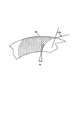
図1a〜図1fは、ワインディング技術における繊維複合材製の中空シャフト10の製造方法の過程を示す。完成した中空シャフト10は、シャフト部11と、シャフト部11の一端にある少なくとも1つの一体フランジ12とを備える。シャフト部11の他端は、原則的に、任意の構成を有し得る。例えば、他端に一体フランジが設けられてもよい。シャフト部11および一体フランジ12は、繊維複合材製であることにより、シャフト部11およびフランジ12は、繊維材料の連続した巻回部を有し、すなわち、1つの動作で巻き付けられる。
1a to 1f show a process of a method for manufacturing a
特に、繊維複合材料の製造に一般的であるようなガラス繊維、炭素繊維、または他の繊維の単繊維、繊維束、フィラメント糸、または粗紡糸が使用される。繊維材料にすでに直接付着し、ひいては、巻回部の敷設時に形成されるか、またはすでに巻き付けられた繊維材料に後でもたらす熱可塑性合成樹脂またはエラストマーが、マトリクスとして使用される。 In particular, glass fibers, carbon fibers, or other single fibers, fiber bundles, filament yarns or rovings as are common in the production of fiber composites are used. A thermoplastic synthetic resin or elastomer that already adheres directly to the fiber material and thus forms at the time of laying of the windings or later brings to the already wound fiber material is used as the matrix.
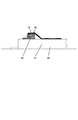
第1の手順ステップ(1)において、繊維材料で作られた交差式の巻回部13の第1の層が、後の中空シャフト10の内側輪郭を表すコア20に形成される。コア20は、シャフト部11に対して、円筒部21を有し、後の中空シャフト10の各フランジ12に対して、半径方向に突出する拡張リング22を有し、拡張リング22の外径は、円筒部21の外径より大きい。コア20は、基本的に1つの部品で構成され得る。しかしながら、例示した実施形態の場合、コアは、いくつかの部品で作られる。拡張リング22は、円筒部21に対して変位可能であり、この目的のために円筒部上に位置付けられる。このように、コア20の長さは、異なる長さを有する中空シャフトを製造するように非常に簡単に調節され得る。コア20上に繊維材料を巻き付け、敷設している間、拡張リング22は、円筒部21に対して静止している。
In the first procedural step (1), a first layer of crossed turns 13 made of fiber material is formed on the core 20 representing the inner contour of the subsequent
拡張リング22は、例示した実施形態の場合、円筒部21の方向に直径が増大する外周部23を有する。円筒部21に対して回転させた側面上に軸受面24が設けられ、この軸受面は、フランジ12の正面壁の形状を画成する。軸受面24は、円筒部21の長手軸Aに垂直方向の平面に延伸し、外周部23とともに取り外しエッジ25を形成する。このエッジ25の機能については、以下でさらに詳細に説明する。この実施形態の代替例において、外周部23も一定の直径をもつようにデザインされ得る。さらに、拡張リング22上には複数のフック26があり、拡張リング22上にわたって、繊維材料の巻回部13がコア20または拡張リング22上に敷設され、ひいては、固定される。このようにして、フランジ12の前壁に続くシャフト部11の内側輪郭が、コア20の構成要素である拡張リング22によって決定されるため、結果的に、中空シャフト10を製造するための固定成形ツールが得られることになる。
In the illustrated embodiment, the
図1aに示すように、巻回部13は、拡張リング22の外周部23上にわたって敷設され、フック26に固定される。フック26は、拡張リング22のショルダ27上に軸方向に支持された支持リング上に設置される。巻回中、外周部23と円筒部21との間に、ほぼ円錐形のガセット14が形成され、巻回部13は、拡張リング22の軸受面24上にも、円筒部21上にも載置されない。
As shown in FIG. 1 a, the winding
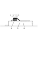
巻回部13の形成中、図1bに示すように、巻回部13の間の拡張リング22のエリアに、繊維材料で作られた1つ以上のインサート15が挿入される。壁の厚みは、描かれたインサート15によって後のフランジ12上で調節される。例示した実施形態において、インサート15は、拡張リング22の外周部23上にわたって重なるとともに、巻回部の円錐形ガセット14上にわたって重なる。これは、両方のエリアが、ガセット14を軸受面24に対して敷設した後に、フランジ12の部分を形成するためである。
During the formation of the winding
図2〜図5に、実現可能なインサートが描かれている。基本的に、1つ以上のインサートが使用可能であることで、フランジ12の厚みがインサートによって得られる。
2 to 5 depict possible inserts. Basically, one or more inserts can be used, so that the thickness of the
特に有益な代替実施形態において、インサートの厚みは、関連するフランジ12の壁厚みが一定になるように適応される。この場合、円筒部21またはシャフト部11の長手中心軸Aに対して90度の角度を有する1つの平面に、フランジ12の正面側および背面側がそれぞれ設置される。この目的のためにインサートが使用され、その全厚みは、拡張リング22上の繊維材料端部の方向、すなわち、この場合は、フック26の方向に増大する。
In a particularly beneficial alternative embodiment, the thickness of the insert is adapted so that the wall thickness of the associated
図2は、リングディスクセグメント15a、15bの形態のインサート15’を示す。ここで、リングディスクセグメント15a、15bの繊維構造は、斜線で示されている。リングディスクセグメント15a、15bは、半径方向に対して同じ種類の繊維構造の配向を有するように配置される。したがって、結果的に、フランジ上の繊維構造が円周方向に均質化される。
FIG. 2 shows an insert 15 'in the form of
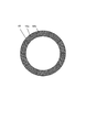
円周方向に均質化のままの繊維構造が、図3に示すリングディスクの形態の縫合されたインサート15によって達成され得る。ここでも、繊維構造は斜線で示されている。外向きに増大する材料の厚みは、最終的に、単一のインサート15によって縫合リングディスクによって達成され得る。
A fiber structure that remains circumferentially homogenized can be achieved by the stitched
図4は、一平面で起こる縫合後に得られた図3のインサート15を切り欠いた部分の平面図を示す。ここで、繊維の配向とリングディスク15の半径方向との間の角度として画成される堆積角度αは、内縁部により小さな角度α1を有し、外縁部により大きな角度α2を有する。リングディスク15が、円錐部14のエリアおよび外周部23のエリアに適用されれば、堆積角度の増大により、後のフランジ12で材料が外向きに厚くなる。
FIG. 4 shows a plan view of the cutout portion of the
図5は、斜線で示されているように、材料の密度および厚みが外向きに増大するように、内縁部よりも外縁部のエリアに、表面積当たりの繊維数が多く設けられる、リングディスク形状のさらなる縫合インサート15’’を示す。 FIG. 5 shows a ring disk configuration where more fibers per surface area are provided in the area of the outer edge than in the inner edge so that the density and thickness of the material increases outwardly as indicated by the diagonal lines A further suture insert 15 '' is shown.
ステップ(c)において最後の巻回部を形成した後、繊維および/またはエラストマー材料の円周層16が、繊維材料をフック26に固定した上で、さらなるステップ(d)において直接巻き付けられ、これで巻回プロセスが終了する。円周層16は、拡張リング22の外周部23のエリアに巻き付けられた繊維材料を締め付け安定させるために役立つ。その後、フック26がある縁部エリアが、ステップ(e)に示すように、切り取られる。ここで、円周層16の一部も切り取られる。拡張リング22および円周層の外径が、取り外しエッジ25または円筒部21の方向に増大するため、繊維材料は、所定の位置に保持される。
After forming the last winding in step (c), the
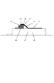
次に、さらなるステップ(f)において、拡張リング22の外周エリア23に設置された巻回部の部分が、フランジ12の一部分を形成するために、エッジ25上にわたって剥がされ、拡張リング22の軸面24に対して適用される。しかしながら、ここで、円周層26下のエリアは、外周部23上にとどまる。エッジ25上にわたった取り外しであるため、すべての繊維が伸張されたままであることが確保される。これは、均質な繊維構造にとって有益である。図1fに示すように、外周部23の剥離は、ストリッパ30によって行われ、ストリッパ30は、拡張リング22の軸受面24の方向に変位されて、静止状態にされる。ストリッパ30は、中心開口を有する分割されたブロックによって形成され、そのブロックの直径は、巻回されたシャフト部11の外径に相当する。軸受面24の方向に変位している間、ストリッパ30は、ガセット14に衝突し、まず、コア20の円筒部21に対して、最終的には、コアの軸受面24に対してガセットを敷設する。拡張リング22の方向にストリッパ30を変位するために、スピンドル32によってストリッパ30に結合された対抗支持体31が、拡張リング22上に取り付けられる。手動または機械的に実行可能であるスピンドル32の回転により、ストリッパ30は、巻回された繊維材料がコア20上に完全に載置されるまで、軸受面24の方向に引き寄せられる。このように形成されたブランクは、次に例えば熱的効果で硬くされ、コア20から分離される。最後に、固定開口が、フランジ12に空けられる。さらに、フランジ12の外周部が平滑化され得る。一方で、フランジエリアの軸受面の処理は不要である。
Next, in a further step (f), the part of the winding part installed in the outer
従来の繊維複合シャフトと比較すると、上記に説明した方法を用いて製造された繊維複合体の中空シャフトは、フランジのエリアの繊維構造が改良された点が優れている。このように、フランジは、非常に均質な繊維構造を有する。さらに、巻回部の繊維は、起伏を生じることなくフランジのエリアに伸張される。敷設中の折り目の形成が回避される。シャフト部11の巻回部が、フランジ12に続くため、フランジがシャフト部11に良好に接続される。壁の厚みは、好ましくは縫合された繊維材料の1つ以上のインサート15、15’、または15’’によって、フランジ12にしっかりと固定して調節され得る。特に、一定の壁厚みが可能である。巻回部間の埋め込みにより、安定した繊維複合物が得られる。
Compared with the conventional fiber composite shaft, the hollow shaft of the fiber composite manufactured using the method described above is superior in that the fiber structure in the area of the flange is improved. Thus, the flange has a very homogeneous fiber structure. Furthermore, the wound fibers are stretched into the flange area without causing undulations. Formation of folds during laying is avoided. Since the winding part of the
さらに、この方法は、低コストの機器に特徴付けられる。円筒部21上に拡張リング22を軸方向に調節可能であることにより、異なる軸方向の長さへの適応が容易になる。しかしながら、シャフトの正面側の内寸法および軸方向の距離に関連するコアのすべてのコンポーネントが、シャフトの巻回中に静止状態にあるため、フランジの正面側間のシャフトの長さは、事前に非常に正確に調節可能である。
Furthermore, this method is characterized by low cost equipment. The ability to adjust the
実施形態によって本発明を上記に詳細に説明してきた。しかしながら、本発明は、この実施形態に限定されるものではなく、特許請求の範囲によって規定されたあらゆる構成を備える。 The invention has been described in detail above by embodiments. However, the present invention is not limited to this embodiment, and includes all configurations defined by the claims.
10…中空シャフト、11…シャフト部、12…フランジ、13…巻回部、14…ガセット、15…インサート、20…コア、21…円筒部、22…拡張リング、23…外周部、24…軸受面、25…取り外しエッジ、26…フック、27…ショルダ、30…ストリッパ、31…対抗支持体、32…スピンドル。
DESCRIPTION OF
Claims (20)
繊維材料の複数の交差式の巻回部(13)が、シャフト部(11)の内側輪郭を表すコア(20)に堆積され、前記コア(20)が、各フランジ(12)に対して、該フランジ(12)の正面壁の形状を画成するための軸受面(24)を有する半径方向の拡張リング(20)を有し、
前記巻回部(13)が、それぞれの前記拡張リング(22)の外周部(23)上全体にわたって敷設され、固定され、
繊維材料で作られた1つ以上のインサート(15、15’、15’’)が、前記巻回部(13)間の前記拡張リング(22)のエリアに配置され、
前記巻回部(13)の仕上げ後、巻回された繊維材料の固定が解除され、前記巻回部(13)の部分が、ストリッパ(30)を用いてエッジ(25)上全体にわたる前記拡張リング(22)の前記外周部(23)から取り外され、前記拡張リングの前記軸受面(24)上に載置されることによって、前記フランジ(12)の一部分を形成する、方法。 A method of manufacturing a hollow shaft having at least one integral flange made of fiber composite, comprising:
A plurality of crossed windings (13) of fibrous material are deposited on the core (20) representing the inner contour of the shaft part (11), said core (20) being against each flange (12), A radial expansion ring (20) having a bearing surface (24) for defining the shape of the front wall of the flange (12);
The winding part (13) is laid and fixed over the entire outer peripheral part (23) of the respective expansion ring (22);
One or more inserts (15, 15 ′, 15 ″) made of fiber material are arranged in the area of the expansion ring (22) between the windings (13),
After finishing of the winding part (13), the wound fiber material is unfixed and the part of the winding part (13) is extended over the edge (25) using a stripper (30). A method of forming a part of the flange (12) by being removed from the outer periphery (23) of the ring (22) and resting on the bearing surface (24) of the expansion ring.
前記シャフト部(11)の内側輪郭を予め決定するための円筒部(21)を有するコア(20)であって、前記円筒部(21)から半径方向に突出し、フランジ(12)の正面壁の形状を予め決定するための軸受面(24)と、外周部(23)と、前記外周部(23)と前記軸受面(24)との間に形成された取り外しエッジ(25)とを有する少なくとも1つの拡張リングを有するコア(20)と、
前記円筒部(21)および前記拡張リング(22)の外周部(23)上に、繊維材料で作られた巻回部(13)を形成するための手段と、
前記エッジ(2)上全体にわたって前記拡張リング(22)の前記外周部(23)から前記巻回部(13)の部分を剥がし、前記部分を前記拡張リング(22)の前記軸受面(24)に対して押圧するために、前記拡張リング(22)の前記軸受面(24)の方向に変位可能な前記シャフト部(11)を取り囲むためのストリッパ(30)と、
を備える装置。 An apparatus for producing a hollow shaft made of a composite material having one shaft portion (11) and one or two integral flanges (12) at the shaft end of the shaft portion (11). And
A core (20) having a cylindrical part (21) for predetermining the inner contour of the shaft part (11), which protrudes in a radial direction from the cylindrical part (21) and is formed on the front wall of the flange (12). At least a bearing surface (24) for predetermining the shape, an outer periphery (23), and a removal edge (25) formed between the outer periphery (23) and the bearing surface (24) A core (20) having one expansion ring;
Means for forming a winding part (13) made of fiber material on the outer peripheral part (23) of the cylindrical part (21) and the expansion ring (22);
The part of the winding part (13) is peeled off from the outer peripheral part (23) of the expansion ring (22) over the edge (2), and the part is removed from the bearing surface (24) of the expansion ring (22). A stripper (30) for enclosing the shaft portion (11) displaceable in the direction of the bearing surface (24) of the expansion ring (22)
A device comprising:
Applications Claiming Priority (2)
| Application Number | Priority Date | Filing Date | Title |
|---|---|---|---|
| DE102008028337.1 | 2008-06-13 | ||
| DE102008028337A DE102008028337B4 (en) | 2008-06-13 | 2008-06-13 | Method for producing a hollow shaft with at least one integral flange made of fiber composite material |
Publications (3)
| Publication Number | Publication Date |
|---|---|
| JP2010042662A true JP2010042662A (en) | 2010-02-25 |
| JP2010042662A5 JP2010042662A5 (en) | 2012-07-19 |
| JP5704739B2 JP5704739B2 (en) | 2015-04-22 |
Family
ID=41317809
Family Applications (1)
| Application Number | Title | Priority Date | Filing Date |
|---|---|---|---|
| JP2009141087A Active JP5704739B2 (en) | 2008-06-13 | 2009-06-12 | Method for manufacturing a hollow shaft having at least one integral flange made of fiber composite |
Country Status (6)
| Country | Link |
|---|---|
| US (1) | US8813335B2 (en) |
| JP (1) | JP5704739B2 (en) |
| KR (1) | KR101165373B1 (en) |
| CN (1) | CN101618605B (en) |
| AU (1) | AU2009202283B2 (en) |
| DE (1) | DE102008028337B4 (en) |
Families Citing this family (25)
| Publication number | Priority date | Publication date | Assignee | Title |
|---|---|---|---|---|
| CN102059798B (en) * | 2010-09-28 | 2012-12-26 | 德州贝诺风力机械设备有限公司 | One-step forming process and die of carbon fiber driving shaft |
| CN102285056B (en) * | 2011-05-31 | 2014-08-27 | 四川泰鑫实业发展有限责任公司 | Thermoplastic-forming processing method for large-diameter PE (Polyurethane) flange head |
| GB201118853D0 (en) * | 2011-11-01 | 2011-12-14 | Camplas Technology Ltd | Improvements in and relating to filament wound hollow members |
| US10654246B2 (en) | 2012-04-28 | 2020-05-19 | General Electric Company | Composite article and methods therefor |
| US9248587B2 (en) | 2012-07-05 | 2016-02-02 | General Electric Company | Apparatus for manufacturing a flanged composite component and methods of manufacturing the same |
| US8535042B1 (en) | 2012-09-14 | 2013-09-17 | General Electric Company | Apparatus for manufacturing a flanged component and methods of manufacturing the same |
| DE102015102438B4 (en) | 2014-02-20 | 2016-09-01 | East-4D Carbon Technology Gmbh | Process for the production of fiber composite hollow bodies with flanges and winding core for carrying out the process |
| DE102014004157B4 (en) | 2014-03-17 | 2015-11-12 | Technische Universität Dresden | Process for the production of load introduction flanges on fiber-reinforced hollow profiles with thermoplastic matrix |
| US9796117B2 (en) | 2014-06-03 | 2017-10-24 | Gkn Aerospace Services Structures Corporation | Apparatus for forming a flange |
| CN104179788B (en) * | 2014-07-08 | 2017-01-18 | 北京航空航天大学 | Thermoplastic composite material transmission shaft with flanges built in |
| DE102015113686B4 (en) | 2014-12-23 | 2023-01-05 | East-4D Carbon Technology Gmbh | Process and device for the production of cylindrical fiber composite bodies with abrupt changes in their profile along the longitudinal axis |
| FR3040014B1 (en) * | 2015-08-14 | 2017-09-08 | Conseil & Technique | METHOD FOR MANUFACTURING AN ANNULAR SHAPE FRAME |
| DE102017101346A1 (en) | 2017-01-25 | 2017-12-28 | Voith Patent Gmbh | METHOD FOR MANUFACTURING A TUBE |
| DE102017113928A1 (en) | 2017-06-23 | 2018-12-27 | Cotesa Gmbh | Fiber composite component and an apparatus and a method for producing a fiber composite component |
| EP3480479B1 (en) | 2017-11-01 | 2024-10-30 | Crompton Technology Group Limited | Transmission shaft |
| EP3608089B1 (en) | 2018-08-10 | 2022-10-12 | Crompton Technology Group Limited | Composite connector and method of manufacturing the same |
| EP3608093B1 (en) | 2018-08-10 | 2024-04-17 | Crompton Technology Group Limited | Composite connector and method of manufacturing the same |
| EP3608095A1 (en) | 2018-08-10 | 2020-02-12 | Crompton Technology Group Limited | Composite connectors and methods of manufacturing the same |
| EP3608092B1 (en) | 2018-08-10 | 2023-06-28 | Crompton Technology Group Limited | Composite connector and method of manufacturing the same |
| EP3608091A1 (en) | 2018-08-10 | 2020-02-12 | Crompton Technology Group Limited | Composite connector and method of manufacturing the same |
| CN109367050B (en) * | 2018-12-10 | 2024-05-03 | 哈尔滨玻璃钢研究院有限公司 | Vertical winding device for composite material thin-wall high-flange cylinder and manufacturing method |
| EP3805623B1 (en) | 2019-10-07 | 2023-11-29 | Crompton Technology Group Limited | Fibre reinforced polymer composite pipes and method of making thereof |
| CN111055413A (en) * | 2019-12-31 | 2020-04-24 | 南京白港复合材料有限公司 | Anti-torque transmission shaft and production process thereof |
| CN112571864B (en) * | 2020-12-29 | 2022-11-04 | 安庆市康明纳包装有限公司 | Production process of medical material |
| CN113352656A (en) * | 2021-05-10 | 2021-09-07 | 哈尔滨玻璃钢研究院有限公司 | Integrated forming method for metal flange and fiber composite material sandwich structure |
Citations (6)
| Publication number | Priority date | Publication date | Assignee | Title |
|---|---|---|---|---|
| JPS4843945B1 (en) * | 1968-06-03 | 1973-12-21 | ||
| JPS55159121U (en) * | 1979-05-04 | 1980-11-15 | ||
| JPS60242043A (en) * | 1984-05-17 | 1985-12-02 | Mitsubishi Electric Corp | Fiber-reinforced plastic molding device |
| JPH04216033A (en) * | 1990-02-23 | 1992-08-06 | Deutsche Forsch & Vers Luft Raumfahrt Ev | Manufacture of composition member using fiber-binding material and its device |
| JPH07174131A (en) * | 1993-04-26 | 1995-07-11 | Toyota Motor Corp | Drive shaft and its manufacture |
| JP2002187204A (en) * | 2000-12-20 | 2002-07-02 | Nikkiso Co Ltd | Manufacturing method for tubular article with flange of fiber reinforced plastics |
Family Cites Families (35)
| Publication number | Priority date | Publication date | Assignee | Title |
|---|---|---|---|---|
| US3651661A (en) * | 1970-02-02 | 1972-03-28 | United Aircraft Corp | Composite shaft with integral end flange |
| FR2242607B1 (en) * | 1973-09-04 | 1976-04-30 | Europ Propulsion | |
| US3970495A (en) * | 1974-07-24 | 1976-07-20 | Fiber Science, Inc. | Method of making a tubular shaft of helically wound filaments |
| US4023835A (en) * | 1975-05-02 | 1977-05-17 | Ewing Engineering Company | Conformable thin-wall shear-resistant coupling and pipe assembly |
| US4126659A (en) * | 1976-07-09 | 1978-11-21 | Lockheed Aircraft Corporation | Method of making a hollow article |
| US4116018A (en) * | 1976-09-16 | 1978-09-26 | The Zeller Corporation | Universal joint |
| US4290836A (en) * | 1978-02-21 | 1981-09-22 | Clow Corporation | Method of making composite pipe having an integral bell end |
| US4348247A (en) * | 1979-02-26 | 1982-09-07 | Rockwell International Corporation | Method of fabricating a reinforced tubular structure |
| US4236386A (en) * | 1979-05-29 | 1980-12-02 | Celanese Corporation | Fiber reinforced composite shaft with metallic connector sleeves mounted by a polygonal surface interlock |
| DE2927955C2 (en) * | 1979-07-11 | 1982-12-30 | Messerschmitt-Bölkow-Blohm GmbH, 8000 München | Method of manufacturing a coupling element |
| US4288267A (en) * | 1980-01-21 | 1981-09-08 | Mcclean Anderson, Inc. | Preliminary and end winding method and apparatus |
| US4391594A (en) * | 1980-08-25 | 1983-07-05 | Lord Corporation | Flexible coupling |
| US4569667A (en) * | 1980-08-25 | 1986-02-11 | Lord Corporation | Flexible coupling |
| DE3321197C2 (en) * | 1983-06-11 | 1986-09-25 | Messerschmitt-Bölkow-Blohm GmbH, 8000 München | Tube, in particular for a safety steering column for motor vehicles |
| US4762583A (en) * | 1985-03-27 | 1988-08-09 | Kaempen Charles E | Method for making composite twine structures |
| US4809402A (en) * | 1985-11-01 | 1989-03-07 | Rockwell International Corporation | Non-metallic composite piano hinge |
| JPS63144827A (en) | 1986-12-06 | 1988-06-17 | Masahiro Tokuyama | Manufacture of flanged hollow shaft |
| US5071506A (en) * | 1987-10-09 | 1991-12-10 | Thiokol Corporation | Equipment for making composite tubes including an inflatable heated bladder and a composite mold having a negative coefficient of thermal expansion |
| DE3922335C1 (en) * | 1989-07-07 | 1990-07-05 | Uranit Gmbh, 5170 Juelich, De | |
| JPH03222723A (en) * | 1990-01-30 | 1991-10-01 | Shitsupu & Ooshiyan Zaidan | Manufacture of fiber reinforced plastic shaft with metallic flange |
| US5225016A (en) * | 1991-08-02 | 1993-07-06 | Rohr Industries, Inc. | Method of manufacturing an advanced composite duct having integral ribs |
| US5551918A (en) * | 1992-02-28 | 1996-09-03 | Lawrie Technology Incorporated | Flexible composite coupling |
| US5460637A (en) * | 1994-03-31 | 1995-10-24 | Du Pont Lanxide Composites L.P. | Ceramic hot gas filter |
| JP3015971B2 (en) * | 1994-04-14 | 2000-03-06 | 旭化成工業株式会社 | Resin-made shaft-integrated hollow mechanism component and injection molding method for manufacturing the same |
| US5725434A (en) * | 1994-11-28 | 1998-03-10 | Deutsche Forschungsanstalt Fur Luft-Un Raumfahrt E. V. | Shaft of fibre-reinforced material |
| DE4442268C1 (en) | 1994-11-28 | 1996-01-04 | Deutsche Forsch Luft Raumfahrt | Composite shaft with integral angle compensating end flange |
| US5720411A (en) * | 1996-03-20 | 1998-02-24 | Advanced Structures, Inc. | Pressure vessels and end closures therefor |
| GB9622799D0 (en) | 1996-11-01 | 1997-01-08 | Flight Refueling Ltd | A rotary power transmission shaft |
| US6461370B1 (en) * | 1998-11-03 | 2002-10-08 | C. R. Bard, Inc. | Temporary vascular filter guide wire |
| AT406183B (en) * | 1998-04-28 | 2000-03-27 | Ellergon Antriebstech Gmbh | CLUTCH COMBINATION OF A COMPENSATING CLUTCH AND A TURN-ELASTIC CLUTCH |
| DE19906618A1 (en) * | 1999-02-17 | 2000-08-24 | Inst Konstruktion Und Verbundb | Making flanged fibrous pipe composites commences with angled winding onto cores, forming layered structure, followed by end trimming and rotating to raise flanges, with assistance from external pressing molds defining final geometry |
| JP2001206778A (en) * | 2000-01-24 | 2001-07-31 | Ishikawajima Harima Heavy Ind Co Ltd | Method and device for producing fiber-reinforced composite member |
| DE10025628A1 (en) * | 2000-05-24 | 2001-11-29 | Sgl Carbon Ag | Unwindable components made of fiber composite materials, processes for their production and their use |
| JP2005147303A (en) * | 2003-11-18 | 2005-06-09 | I & P Kk | Shaft and manufacturing method thereof |
| DE102006042301B4 (en) * | 2006-09-08 | 2018-02-22 | Ellergon Antriebstechnik Gmbh | Diaphragm compensation clutch and hole reveal connection |
-
2008
- 2008-06-13 DE DE102008028337A patent/DE102008028337B4/en active Active
-
2009
- 2009-06-09 AU AU2009202283A patent/AU2009202283B2/en active Active
- 2009-06-12 US US12/484,173 patent/US8813335B2/en active Active
- 2009-06-12 JP JP2009141087A patent/JP5704739B2/en active Active
- 2009-06-15 KR KR1020090052965A patent/KR101165373B1/en active IP Right Grant
- 2009-06-15 CN CN2009103032291A patent/CN101618605B/en active Active
Patent Citations (6)
| Publication number | Priority date | Publication date | Assignee | Title |
|---|---|---|---|---|
| JPS4843945B1 (en) * | 1968-06-03 | 1973-12-21 | ||
| JPS55159121U (en) * | 1979-05-04 | 1980-11-15 | ||
| JPS60242043A (en) * | 1984-05-17 | 1985-12-02 | Mitsubishi Electric Corp | Fiber-reinforced plastic molding device |
| JPH04216033A (en) * | 1990-02-23 | 1992-08-06 | Deutsche Forsch & Vers Luft Raumfahrt Ev | Manufacture of composition member using fiber-binding material and its device |
| JPH07174131A (en) * | 1993-04-26 | 1995-07-11 | Toyota Motor Corp | Drive shaft and its manufacture |
| JP2002187204A (en) * | 2000-12-20 | 2002-07-02 | Nikkiso Co Ltd | Manufacturing method for tubular article with flange of fiber reinforced plastics |
Also Published As
| Publication number | Publication date |
|---|---|
| KR101165373B1 (en) | 2012-07-13 |
| US8813335B2 (en) | 2014-08-26 |
| US20090308477A1 (en) | 2009-12-17 |
| CN101618605B (en) | 2012-09-05 |
| JP5704739B2 (en) | 2015-04-22 |
| DE102008028337A1 (en) | 2009-12-17 |
| AU2009202283A1 (en) | 2010-01-07 |
| KR20090129969A (en) | 2009-12-17 |
| CN101618605A (en) | 2010-01-06 |
| DE102008028337B4 (en) | 2013-09-26 |
| AU2009202283B2 (en) | 2011-06-23 |
Similar Documents
| Publication | Publication Date | Title |
|---|---|---|
| JP5704739B2 (en) | Method for manufacturing a hollow shaft having at least one integral flange made of fiber composite | |
| JP2010042662A5 (en) | ||
| US8960065B2 (en) | Method for braiding reinforcing fibers with variation in the inclination of the braided fibers | |
| RU2012101963A (en) | METHOD FOR MANUFACTURING COMPOSITE CONNECTING ROD AND CONNECTING ROD MANUFACTURED IN SUCH METHOD | |
| HU227349B1 (en) | Method for making fibrous preforms for producing annular parts from a composite material | |
| CA2557366A1 (en) | Winding core and associated method | |
| RU2523072C2 (en) | Operation of reinforcing fibre braider | |
| US10668672B2 (en) | Radially extending composite structures | |
| JP2003009722A (en) | Method for producing rod body | |
| US6284103B1 (en) | Suction roll shell in a paper-making machine and method of manufacturing same | |
| US9975298B2 (en) | Filament winding apparatus | |
| US20160377148A1 (en) | Methods of coupling a flywheel rim and a shaft | |
| JP2008290269A (en) | Method for forming through-hole in fiber-reinforced resin sheet | |
| US8029632B2 (en) | Method for producing a belt package for a pneumatic vehicle tire | |
| CN114180394A (en) | Wiring structure of winding machine | |
| JP5431285B2 (en) | Fishing rod guide and fishing rod equipped with fishing line guide | |
| US20050017122A1 (en) | Apparatus and method for forming enlarged base on yarn carrier, and yarn carrier with enlarged base | |
| JP4236293B2 (en) | Hose and manufacturing method thereof | |
| JP4392734B2 (en) | Manufacturing method of housing | |
| JP3703563B2 (en) | Manufacturing method of tubular fabric with ribs and shaped body used in the manufacturing method | |
| JPH06278671A (en) | Fiber-reinforced thermosetting resin pipe for bicycle frame and its manufacture | |
| JP3430982B2 (en) | Preform manufacturing system | |
| JPH119148A (en) | Fishing rod and its production | |
| JP2012111135A (en) | Method for manufacturing hollow material, and thickness taking plate used therein | |
| JPH1122554A (en) | Manufacture of pressure container |
Legal Events
| Date | Code | Title | Description |
|---|---|---|---|
| A711 | Notification of change in applicant |
Free format text: JAPANESE INTERMEDIATE CODE: A711 Effective date: 20100707 |
|
| A521 | Request for written amendment filed |
Free format text: JAPANESE INTERMEDIATE CODE: A523 Effective date: 20120606 |
|
| A621 | Written request for application examination |
Free format text: JAPANESE INTERMEDIATE CODE: A621 Effective date: 20120606 |
|
| A977 | Report on retrieval |
Free format text: JAPANESE INTERMEDIATE CODE: A971007 Effective date: 20131023 |
|
| A131 | Notification of reasons for refusal |
Free format text: JAPANESE INTERMEDIATE CODE: A131 Effective date: 20131119 |
|
| A521 | Request for written amendment filed |
Free format text: JAPANESE INTERMEDIATE CODE: A523 Effective date: 20140213 |
|
| A131 | Notification of reasons for refusal |
Free format text: JAPANESE INTERMEDIATE CODE: A131 Effective date: 20140916 |
|
| A521 | Request for written amendment filed |
Free format text: JAPANESE INTERMEDIATE CODE: A523 Effective date: 20141211 |
|
| TRDD | Decision of grant or rejection written | ||
| A01 | Written decision to grant a patent or to grant a registration (utility model) |
Free format text: JAPANESE INTERMEDIATE CODE: A01 Effective date: 20150127 |
|
| A61 | First payment of annual fees (during grant procedure) |
Free format text: JAPANESE INTERMEDIATE CODE: A61 Effective date: 20150223 |
|
| R150 | Certificate of patent or registration of utility model |
Ref document number: 5704739 Country of ref document: JP Free format text: JAPANESE INTERMEDIATE CODE: R150 |
|
| R250 | Receipt of annual fees |
Free format text: JAPANESE INTERMEDIATE CODE: R250 |
|
| R250 | Receipt of annual fees |
Free format text: JAPANESE INTERMEDIATE CODE: R250 |
|
| R250 | Receipt of annual fees |
Free format text: JAPANESE INTERMEDIATE CODE: R250 |
|
| R250 | Receipt of annual fees |
Free format text: JAPANESE INTERMEDIATE CODE: R250 |
|
| R250 | Receipt of annual fees |
Free format text: JAPANESE INTERMEDIATE CODE: R250 |
|
| R250 | Receipt of annual fees |
Free format text: JAPANESE INTERMEDIATE CODE: R250 |
|
| S533 | Written request for registration of change of name |
Free format text: JAPANESE INTERMEDIATE CODE: R313533 |
|
| R350 | Written notification of registration of transfer |
Free format text: JAPANESE INTERMEDIATE CODE: R350 |
|
| R250 | Receipt of annual fees |
Free format text: JAPANESE INTERMEDIATE CODE: R250 |