RU2523072C2 - Operation of reinforcing fibre braider - Google Patents
Operation of reinforcing fibre braider Download PDFInfo
- Publication number
- RU2523072C2 RU2523072C2 RU2012139831/12A RU2012139831A RU2523072C2 RU 2523072 C2 RU2523072 C2 RU 2523072C2 RU 2012139831/12 A RU2012139831/12 A RU 2012139831/12A RU 2012139831 A RU2012139831 A RU 2012139831A RU 2523072 C2 RU2523072 C2 RU 2523072C2
- Authority
- RU
- Russia
- Prior art keywords
- mandrel
- core
- ring
- reinforcing fibers
- axis
- Prior art date
Links
Images


Classifications
-
- D—TEXTILES; PAPER
- D04—BRAIDING; LACE-MAKING; KNITTING; TRIMMINGS; NON-WOVEN FABRICS
- D04C—BRAIDING OR MANUFACTURE OF LACE, INCLUDING BOBBIN-NET OR CARBONISED LACE; BRAIDING MACHINES; BRAID; LACE
- D04C3/00—Braiding or lacing machines
- D04C3/40—Braiding or lacing machines for making tubular braids by circulating strand supplies around braiding centre at equal distances
-
- D—TEXTILES; PAPER
- D04—BRAIDING; LACE-MAKING; KNITTING; TRIMMINGS; NON-WOVEN FABRICS
- D04C—BRAIDING OR MANUFACTURE OF LACE, INCLUDING BOBBIN-NET OR CARBONISED LACE; BRAIDING MACHINES; BRAID; LACE
- D04C3/00—Braiding or lacing machines
- D04C3/48—Auxiliary devices
-
- D—TEXTILES; PAPER
- D04—BRAIDING; LACE-MAKING; KNITTING; TRIMMINGS; NON-WOVEN FABRICS
- D04C—BRAIDING OR MANUFACTURE OF LACE, INCLUDING BOBBIN-NET OR CARBONISED LACE; BRAIDING MACHINES; BRAID; LACE
- D04C1/00—Braid or lace, e.g. pillow-lace; Processes for the manufacture thereof
- D04C1/02—Braid or lace, e.g. pillow-lace; Processes for the manufacture thereof made from particular materials
-
- D—TEXTILES; PAPER
- D10—INDEXING SCHEME ASSOCIATED WITH SUBLASSES OF SECTION D, RELATING TO TEXTILES
- D10B—INDEXING SCHEME ASSOCIATED WITH SUBLASSES OF SECTION D, RELATING TO TEXTILES
- D10B2505/00—Industrial
- D10B2505/02—Reinforcing materials; Prepregs
Abstract
Description
Изобретение относится к способу работы оплеточной машины, содержащей кольцо с установленными на нем бобинами армирующих волокон, для последовательного плетения нескольких слоев армирующих волокон вокруг одной оправки, перемещаемой несколько раз через кольцо, или вокруг нескольких оправок, перемещаемых друг за другом через кольцо.The invention relates to a method for operating a braiding machine comprising a ring with bobbins of reinforcing fibers mounted thereon, for sequentially weaving several layers of reinforcing fibers around one mandrel, moved several times through the ring, or around several mandrels moved one after another through the ring.
Уровень техникиState of the art
Оплеточная машина позволяет изготовить деталь из композитного материала посредством плетения вокруг оправки и по всей ее длине одного или нескольких слоев армирующих волокон, укладываемых друг на друга.Braiding machine allows you to make a part of a composite material by weaving around the mandrel and along its entire length of one or more layers of reinforcing fibers stacked on top of each other.
После формирования различных слоев пакет, образованный оправкой и уложенными на нее слоями, помещают в пресс-форму для впрыска смолы в эти слои. После этого смолу подвергают полимеризации, например, посредством нагрева для получения жесткой заготовки.After the formation of various layers, the packet formed by the mandrel and the layers laid on it is placed in a mold for injection of resin into these layers. After that, the resin is polymerized, for example, by heating to obtain a rigid preform.
Оплеточная машина 1, показанная на фиг.1, в основном содержит кольцо 2, расположенное в вертикальной плоскости, то есть ось АХ вращения этого кольца является горизонтальной. На этом кольце 2 установлен ряд бобин армирующих волокон 3, которые сходятся в точке или области, находящейся на оси АХ и расположенной спереди плоскости кольца. Таким образом, эти волокна совместно образуют по существу конусную форму.The
После запуска цикла плетения оправку 4 перемещают вдоль оси АХ таким образом, чтобы она прошла через кольцо 2 за точку схождения волокон. В это же время бобины, установленные на кольце 2 при помощи подвижных держателей с приводами, приводят во вращение для изготовления чулка из усиливающих волокон на наружной поверхности оправки 4.After starting the weaving cycle, the
Указанный чулок покрывает оправку по всей ее длине после полного прохода оправки через кольцо, то есть после того, как она окажется за точкой схождения волокон, которая смещена относительно кольца.The specified stocking covers the mandrel along its entire length after the mandrel has completely passed through the ring, that is, after it is beyond the point of convergence of the fibers, which is offset from the ring.
Затем слой армирующих волокон разрезают позади оправки, и оправку снимают и опять помещают после кольца, чтобы опять пропустить через него для формирования второго слоя армирующих волокон, накладываемого в радиальном направлении на первый слой.Then, the layer of reinforcing fibers is cut behind the mandrel, and the mandrel is removed and placed again after the ring to again pass through it to form a second layer of reinforcing fibers radially superimposed on the first layer.
На практике задний конец оправки жестко соединяют с задним стержнем, а ее передний конец жестко соединяют с передним стержнем, с помощью которых ее протягивают через кольцо. Для этого оправка может содержать на каждом из своих концов резьбовое отверстие, при этом каждый стержень содержит соответствующий резьбовой конец, который завинчивают в это резьбовое отверстие.In practice, the rear end of the mandrel is rigidly connected to the rear shaft, and its front end is rigidly connected to the front shaft, with which it is pulled through the ring. To this end, the mandrel may comprise a threaded hole at each of its ends, with each rod having a corresponding threaded end which is screwed into this threaded hole.
Во время работы слой переплетаемых волокон окружает передний стержень и формируется вокруг оправки по мере ее перемещения вдоль оси АХ за счет тянущего усилия, прикладываемого к этому стержню.During operation, a layer of interwoven fibers surrounds the front shaft and is formed around the mandrel as it moves along the axis AX due to the pulling force applied to this shaft.
После того как указанный слой полностью сформирован, через оплетку позади оправки пропускают веревку и эту веревку натягивают параллельно оси АХ для удержания точки схождения волокон спереди кольца и приблизительно на оси АХ.After the specified layer is fully formed, a rope is passed through the braid behind the mandrel and this rope is pulled parallel to the axis AX to maintain the point of convergence of the fibers in front of the ring and approximately on the axis AX.
После этого оплетку из армирующих волокон можно обрезать между оправкой и областью, в которой через нее проходит веревка. После этого этапа передний стержень вывинчивают из переднего конца оправки, а оправку отвинчивают с переднего конца заднего стержня и удаляют вместе с уложенным на нее слоем армирующих волокон.After that, a braid of reinforcing fibers can be cut between the mandrel and the area in which the rope passes through it. After this stage, the front rod is unscrewed from the front end of the mandrel, and the mandrel is unscrewed from the front end of the rear rod and removed together with a layer of reinforcing fibers laid on it.
Затем оправку вместе со слоем волокон опять помещают после кольца. Задний конец стержня, проходящий через кольцо, завинчивают в передний конец оправки, и этот стержень, который на предыдущем этапе был задним стержнем, становится передним стержнем.Then the mandrel together with the fiber layer is again placed after the ring. The rear end of the shaft passing through the ring is screwed into the front end of the mandrel, and this shaft, which was the rear shaft in the previous step, becomes the front shaft.
Другой стержень завинчивают на заднем конце оправки. Указанные стержни, неподвижно соединенные с оправкой, удерживаются в положении на оси АХ при помощи нескольких опорных подшипников, отстоящих друг от друга вдоль оси АХ.The other rod is screwed at the rear end of the mandrel. These rods fixedly connected to the mandrel are held in position on the axis AX with the help of several thrust bearings spaced from each other along the axis AX.
На практике, когда точку схождения волокон удерживают при помощи веревки во время удаления оправки и ее повторной установки, положение этой точки схождения плохо поддается контролю для того, чтобы она оставалась на оси АХ, поэтому эта точка схождения смещается в радиальном направлении относительно оси АХ.In practice, when the point of convergence of the fibers is held with a rope during removal of the mandrel and its re-installation, the position of this point of convergence is difficult to control so that it remains on the axis AX, therefore this point of convergence shifts radially relative to the axis AX.
Таким образом, когда оправку опять устанавливают в машину и ее передний конец помещают в положение опоры на зону схождения волокон, радиальное смещение этой зоны схождения приводит к локальному нарушению упорядоченности армирующих волокон в зоне конца оправки. Это приводит к снижению механической прочности получаемой черновой детали в зоне этого конца.Thus, when the mandrel is again installed in the machine and its front end is placed in the support position on the convergence zone of fibers, the radial displacement of this convergence zone leads to a local violation of the ordering of the reinforcing fibers in the area of the end of the mandrel. This leads to a decrease in the mechanical strength of the resulting draft part in the area of this end.
Чтобы избежать этой проблемы, оплеточную машину необходимо запускать для повторной центровки зоны схождения углеродных волокон до повторной установки оправки. Однако это занимает много времени в рамках процесса изготовления и приводит к увеличению длины армирующих волокон, необходимой для плетения каждого слоя.To avoid this problem, the braiding machine must be started to re-center the carbon fiber toe zone before re-installing the mandrel. However, this takes a lot of time as part of the manufacturing process and leads to an increase in the length of the reinforcing fibers necessary for weaving each layer.
Настоящее изобретение направлено на устранение указанного недостатка.The present invention seeks to remedy this drawback.
Раскрытие изобретенияDisclosure of invention
Объектом изобретения является способ работы оплеточной машины, содержащей кольцо с установленными на нем бобинами армирующих волокон для последовательного плетения нескольких слоев армирующих волокон вокруг одной оправки, перемещаемой несколько раз через кольцо, или вокруг нескольких оправок, перемещаемых друг за другом через кольцо, при этом каждая оправка установлена на держателе, выполненном с возможностью перемещения через кольцо вдоль его оси, в котором после прохода оправки через кольцо армирующих волокон разрезают позади оправки для обеспечения возможности ее удаления.The object of the invention is a method of operating a braiding machine comprising a ring with reinforcing fiber bobbins mounted thereon for sequentially weaving several layers of reinforcing fibers around one mandrel, moved several times through the ring, or around several mandrels moving one after another through the ring, each mandrel mounted on a holder configured to move through the ring along its axis, in which, after the mandrel passes through the ring of reinforcing fibers, it is cut behind the def Applicants to permit its removal.
Согласно изобретению позади оправки устанавливают на держателе сердечник и неподвижно соединяют его с оправкой; после прохода оправки через кольцо армирующие волокна стягивают вокруг сердечника при помощи петли, охватывающей армирующие волокна; а перед удалением оправки армирующие волокна разрезают между оправкой и сердечником.According to the invention, a core is mounted on the holder behind the mandrel and motionlessly connected to the mandrel; after the mandrel has passed through the ring, the reinforcing fibers are pulled around the core with a loop covering the reinforcing fibers; and before removing the mandrel, the reinforcing fibers are cut between the mandrel and the core.
Такой способ позволяет удерживать волокна в положении идеальной центровки на оси кольца во время удаления оправки. При этом стоимость изготовления снижается, так как больше нет необходимости запускать оплеточную машину для повторной центровки оплетки перед установкой новой оправки.This method allows you to keep the fibers in the ideal centering position on the axis of the ring during removal of the mandrel. At the same time, the manufacturing cost is reduced, since it is no longer necessary to start the braiding machine to re-center the braid before installing a new mandrel.
Предпочтительно используют сердечник, содержащий по меньшей мере одну кольцевую канавку, образующую полость, в которую помещают петлю для стягивания усиливающих волокон.Preferably, a core is used comprising at least one annular groove forming a cavity in which a loop is placed to tighten the reinforcing fibers.
Предпочтительно используют сердечник, имеющий, по меньшей мере частично, конусную форму или сердечник, имеющий двухконусную форму.Preferably, a core having at least partially a conical shape or a core having a biconical shape is used.
Предпочтительно концы сердечника имеют разные сечения, соответствующие сечению оправки, установленной спереди этого сердечника, и сечению оправки, установленной сзади этого сердечника.Preferably, the ends of the core have different cross sections corresponding to the cross section of the mandrel mounted on the front of this core and the cross section of the mandrel mounted on the back of this core.
Предпочтительно используют держатель оправки и сердечника, выполненный в виде одного или нескольких стержней, расположенных вдоль оси кольца и установленных по меньшей мере на двух опорных подшипниках, расположенных по обе стороны от кольца.Preferably, a mandrel and core holder is used, made in the form of one or more rods located along the axis of the ring and mounted on at least two thrust bearings located on both sides of the ring.
Краткое описание чертежейBrief Description of the Drawings
На фиг.1 показан процесс плетения слоя углеродных волокон вокруг оправки при помощи оплеточной машины, вид в перспективе;Figure 1 shows the process of weaving a layer of carbon fibers around the mandrel using a braiding machine, perspective view;
на фиг.2 показан сердечник, используемый в способе согласно изобретению, вид в перспективе;figure 2 shows the core used in the method according to the invention, a perspective view;
на фиг.3 схематично показан этап способа согласно изобретению, на котором усиливающие волокна собирают и стягивают вокруг сердечника;figure 3 schematically shows a step of the method according to the invention, in which reinforcing fibers are collected and pulled around the core;
на фиг.4 показан этап изготовления первого слоя усиливающих волокон вокруг оправки;figure 4 shows the manufacturing step of the first layer of reinforcing fibers around the mandrel;
на фиг.5 показан этап способа, на котором стягивают волокна вокруг сердечника, установленного сзади оправки, и разрезают сплетенные волокна спереди и сзади оправки;Fig. 5 shows a method step in which fibers are pulled together around a core installed behind the mandrel and the braided fibers are cut in front and behind the mandrel;
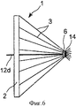
на фиг.6 показан этап способа согласно изобретению, на котором удаляют оправку с уложенным на нее плетеным слоем;6 shows a step of the method according to the invention, in which the mandrel with the woven layer laid on it is removed;
на фиг.7 показаны оправка и сердечник, вид сбоку в разрезе;7 shows a mandrel and a core, a side view in section;
на фиг.8 показаны другая оправка и соединенный с ней другой сердечник, вид сбоку в разрезе.on Fig shows another mandrel and connected to it another core, a side view in section.
Осуществление изобретенияThe implementation of the invention
Основополагающей идеей изобретения является установка сердечника на оси АХ позади оправки и использование этого сердечника для удержания зоны схождения армирующих волокон центрованной на оси АХ во время удаления оправки. В частности, после выполнения плетением слоя волокон по всей длине оправки вокруг волокон пропускают петлю или хомут, которые затягивают для прижатия волокон к сердечнику с целью удержания зоны схождения этих волокон центрированной на оси АХ.The fundamental idea of the invention is the installation of a core on the axis of the AX behind the mandrel and the use of this core to keep the zone of convergence of the reinforcing fibers centered on the axis of the AX during removal of the mandrel. In particular, after a layer of fibers is woven along the entire length of the mandrel, a loop or clamp is passed around the fibers, which is tightened to press the fibers to the core in order to keep the convergence zone of these fibers centered on the axis AX.
Сердечник 5, показанная отдельно на фиг.2, имеет в целом форму тела вращения вокруг оси АХ. В данном случае его наружная поверхность в целом является конусной, и она содержит две кольцевые канавки 8 и 9, отстоящие друг от друга вдоль оси АХ.The
Каждая канавка 8, 9 образует полость, предназначенную для захождения в нее петли, стягивающей сердечник вместе с охватывающими его волокнами, чтобы указанная петля не могла скользить вдоль наружной поверхности 7 после того, как ее затянут в достаточной степени, чтобы удерживать зону схождения волокон в требуемом положении.Each
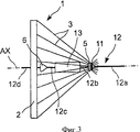
На практике, как показано на фиг.3, армирующие волокна 3 совместно образуют конусную форму, вершина которой, находящаяся на оси АХ, соответствует зоне их схождения. Когда сердечник 5 оказывается на уровне этой зоны вдоль оси АХ, его охватывают армирующие волокна, которые опираются на его наружную поверхность.In practice, as shown in figure 3, the reinforcing
В этой ситуации петля или хомут 11, охватывающие и стягивающие волокна, расположенные в одной из канавок 8 или 9 сердечника 5, позволяют удерживать армирующие волокна в положении, в котором зона их схождения остается на оси АХ без радиального смещения.In this situation, the loop or
На фиг.3 детально показана оплеточная установка 1 в начале операции плетения. Установка содержит кольцо 2 с установленным на ней рядом бобин армирующих волокон 3, держатель 12 с установленной на нем оправкой 13, а также первый сердечник 5 и второй сердечник 6, образующие узел, расположенный вдоль оси АХ.Figure 3 shows in detail the
Первый сердечник 5 находится спереди переднего конца оправки 13, то есть конца оправки, наиболее удаленного от кольца 2. Он показан справа на фиг.3. Второй сердечник 6, в свою очередь, находится позади заднего конца оправки 13.The
Петля 11 стягивает все армирующие волокна 3 вокруг сердечника 5, а оправка 13 находится во внутреннем пространстве, ограниченном конусной поверхностью, образованной армирующими волокнами 3, с целью плетения чулка из армирующих волокон вокруг оправки по всей ее длине.The
Держатель 12 может состоять из четырех стержней 12а, 12b, 12 с, 12d. В этом случае каждый стержень содержит резьбовые концы, и каждый конец оправки 13 и двух сердечников 5 и 6 содержит резьбовое отверстие, в которое завинчивают конец стержня.The
Соединение стержней с оправкой 13 и с сердечниками 5 и 6 осуществляется путем завинчивания одного конца стержня 12а на переднем конце сердечника 5, завинчивания переднего конца стержня 12b на заднем конце сердечника 5 и завинчивания заднего конца стержня 12b на переднем конце оправки 13. Аналогично, передний конец стержня 12 с завинчивают на заднем конце оправки 13, задний конец стержня 12 с завинчивают на переднем конце сердечника 6 и, наконец, передний конец стержня 12d завинчивают на заднем конце сердечника 6.The rods are connected to the
Узел, образованный оправкой 13, двумя сердечниками 5, 6 и стержнями 12а - 12 с, представляет собой жесткую конструкцию, удерживаемую в заданном положении на оси АХ с одной стороны первым задним опорным подшипником (не показан), который находится сзади кольца 2, то есть на фигуре слева от кольца, а с другой стороны -тяговым средством (не показано), с которым неподвижно соединен передний конец стержня 12а.The node formed by the
Указанный опорный подшипник содержит неподвижный корпус, который при необходимости может быть выполнен съемным, содержащий в своей верхней части элементы для установки стержня с целью его расположения на оси АХ и его одновременной блокировки по меньшей мере от вращения, а при необходимости и от поступательного движения. Аналогично, тяговое средство содержит элементы для установки стержня и его удержания в заданном положении на оси АХ с элементами блокировки вращения и поступательного движения для приложения тягового усилия к этому стержню вдоль оси АХ.The specified thrust bearing contains a stationary housing, which, if necessary, can be made removable, containing in its upper part elements for mounting the rod with the aim of its location on the axis AX and its simultaneous blocking at least from rotation, and, if necessary, from translational motion. Similarly, the traction means contains elements for installing the rod and holding it in a predetermined position on the axis AX with elements of rotation blocking and translational motion for applying traction to this rod along the axis AX.
Операция плетения начинается с перемещения жесткого узла, образованного держателем 12 с оправкой 13 и сердечниками 5 и 6, вперед, то есть вправо на фиг.3, посредством приведения в действие тягового средства.The weaving operation begins with the movement of the rigid node formed by the
При этом по мере перемещения оправки происходит плетение чулка вокруг оправки на уровне точки схождения волокон, что схематично показано на фиг.4, где плетением выполнена примерно половина чулка, при этом точка схождения усиливающих волокон находится по существу на половине длины оправки.In this case, as the mandrel moves, the stocking weaves around the mandrel at the level of the fiber convergence point, which is schematically shown in Fig. 4, where approximately half of the stocking is made by weaving, while the point of convergence of the reinforcing fibers is essentially half the length of the mandrel.
По мере продолжения этого движения по всей длине оправки 13 формируется слой армирующих волокон, пока второй сердечник 6 не окажется на уровне зоны схождения волокон, что соответствует ситуации, показанной на фиг.5.As this movement continues along the entire length of the
В этот момент установку останавливают, и вокруг второго сердечника 6 пропускают петлю или хомут 14 для удержания армирующих волокон в положении на уровне зоны их схождения. После осуществления этой операции плетеный слой 16 армирующих волокон разрезают с одной стороны между передним концом оправки 13 и первым сердечником 5, а с другой стороны - между задним концом оправки 13 и вторым сердечником 6. Разрезание осуществляют при помощи режущих инструментов типа ножниц или их аналога.At this point, the installation is stopped and a loop or
После разрезания слоя армирующих волокон спереди и сзади оправки 13 эту оправку удаляют. В частности, предпочтительно временно устанавливают сзади кольца 2 второй задний опорный подшипник дополнительно к первому заднему опорному подшипнику на некотором расстоянии от первого вдоль оси АХ, чтобы полностью удерживать стержень 12d в положении на оси АХ. Поскольку на этом стержне 12d установлен второй сердечник 6, его удержания двумя задними опорными подшипниками достаточно, чтобы удерживать зону схождения волокон 3 в положении на оси АХ без радиального смещения.After cutting the layer of reinforcing fibers in front and behind the
На этой стадии стержень 12а отсоединяют от тягового средства, чтобы узел, образованный стержнем 12 с, оправкой 13 с уложенным на нее слоем, а также стержнями 12b и 12а, можно было отсоединить от второго сердечника 6 посредством вывинчивания заднего конца стержня 12 с, который был завинчен в передний конец этого сердечника 6.At this stage, the
После этого можно снять стержень 12а посредством его вывинчивания из переднего конца первого сердечника 5. После этого стержень 12а с одной стороны завинчивают в передний конец второго сердечника 6, а с другой стороны - опять соединяют с тяговым средством. Одновременно один или два дополнительных передних опорных подшипника предпочтительно временно устанавливают для удержания указанного стержня 12а коаксиально с осью АХ.After that, the
На этой стадии стержень 12d снимают, вывинчивая его из заднего конца второго сердечника 6, после чего этот второй сердечник 6 удерживает передний стержень 12а, который, в свою очередь, соединен с тяговым средством и с временно установленными передними опорными подшипниками.At this stage, the
После этого первый сердечник 5 отвинчивают от переднего конца стержня 12b, затем завинчивают на заднем конце стержня 12 с. Узел, последовательно образованный первым сердечником 5, стержнем 12с, оправкой 13 и стержнем 12b устанавливают, завинчивая передний конец стержня 12b на заднем конце второго сердечника 6, а затем завинчивая передний конец стержня 12d на заднем конце первого сердечника 5.After that, the
На этой стадии расположение элементов опять соответствует расположению, показанному на фиг.3, за исключением того, что положения первого и второго сердечников 5 и 6 поменялись по сравнению с положениями, которые они занимали на фиг.3.At this stage, the arrangement of the elements again corresponds to the arrangement shown in FIG. 3, except that the positions of the first and
Теперь можно начинать плетение нового слоя армирующих волокон, накладываемого на первый слой, после удаления переднего и заднего опорных подшипников, которые, в случае необходимости, могли быть установлены временно. Таким образом, вокруг оправки выполняют плетением различные слои вплоть до получения заданной толщины.Now we can begin weaving a new layer of reinforcing fibers superimposed on the first layer, after removing the front and rear thrust bearings, which, if necessary, could be installed temporarily. Thus, various layers are woven around the mandrel until the desired thickness is obtained.
В представленном на чертежах примере сердечники 5 и 6 отделены от оправки 13 относительно большим расстоянием, но предпочтительно это расстояние можно уменьшить, что позволяет уменьшить длину армирующих волокон, необходимую для каждого слоя, и за счет этого сократить расходы на изготовление.In the example shown in the drawings, the
Как показано на фиг.7, расстояние, отделяющее каждый сердечник от оправки, можно уменьшить до минимального значения d, которое по существу соответствует минимальному пространству, необходимому для прохода инструмента разрезания слоя армирующих волокон.As shown in FIG. 7, the distance separating each core from the mandrel can be reduced to a minimum value of d, which essentially corresponds to the minimum space required for the passage of the tool to cut the layer of reinforcing fibers.
В представленном на чертежах примере сердечник 5 содержит две канавки, позволяющие стягивать армирующие волокна двумя соответствующими петлями или хомутами, но при этом вполне можно использовать сердечник только с одной канавкой, при этом выбор числа канавок и хомутов или петлей в основном зависит от условий изготовления.In the example shown in the drawings, the
Точно так же наружную форму сердечника 5 выбирают в зависимости от условий изготовления. В примере, представленном на фиг.8, сердечник 18 расположен между двумя последовательно расположенными оправками 13 и 17, имеющими разные диаметры и установленными друг за другом на держателе.Similarly, the outer shape of the
В этих условиях сердечник 18 имеет двухконусную форму, при этом на конце 19, ближайшем к оправке 13, его сечение соответствует сечению оправки 13, а на конце 21, ближайшем к оправке 17, его сечение соответствует сечению этой оправки 17. Наружная поверхность сердечника 18 соединяет контуры указанных двух частей, образуя при этом в своей центральной области сужение 23, образующее кольцевую канавку, предназначенную для прохождения петли с целью стягивания армирующих волокон плетеного слоя 22.Under these conditions, the
Предпочтительно диаметр конца 19 по существу меньше диаметра оправки 13, а диаметр конца 21 по существу больше диаметра оправки 17, чтобы оплетку можно было раздвигать для облегчения установки указанной оправки между двумя операциями плетения.Preferably, the diameter of the
Такой сердечник обеспечивает непрерывность плетеного слоя 22 между первой и второй оправками 13 и 17, поэтому ориентация волокон не нарушается при переходе от одной оправки к другой.Such a core ensures the continuity of the woven
Так же, как и в примере, показанном на фиг.7, сердечник 18 отдален от каждой из оправок 13 и 17 на расстояние d, которое соответствует минимальному пространству для прохода инструмента разрезания слоя усиливающих волокон.As in the example shown in Fig. 7, the
Кроме того, необходимо отметить, что в примере, представленном на фиг.8, сердечник имеет двухконусную форму, которая является асимметричной. Однако в некоторых случаях изготовления, в частности при плетении слоев армирующих волокон вокруг разных оправок одинакового диаметра, можно использовать сердечник с симметричной двухконусной формой.In addition, it should be noted that in the example shown in Fig. 8, the core has a biconical shape, which is asymmetric. However, in some manufacturing cases, in particular when weaving layers of reinforcing fibers around different mandrels of the same diameter, a core with a symmetrical biconical shape can be used.
В различных примерах, представленных на чертежах, оправки имеют простую форму тела вращения так же, как и сердечники, однако изобретение можно также применять для ситуаций, в которых оправка или оправки имеют любое сечение, например прямоугольное. В этом случае сердечники также могут иметь сечение, соответствующее сечению оправок.In the various examples presented in the drawings, the mandrels have a simple body shape of rotation as well as the cores, however, the invention can also be applied to situations in which the mandrel or mandrels have any cross section, for example rectangular. In this case, the cores may also have a cross section corresponding to the cross section of the mandrels.
Когда оправки и сердечники имеют формы, не являющиеся телами вращения, предпочтительно эти элементы не должны поворачиваться вокруг оси АХ во время формирования слоя армирующих волокон. В этом случае соединение между каждым стержнем-держателем и каждой оправкой или сердечником обеспечивают при помощи поперечной шпонки, проходящей через конец рассматриваемого элемента и стержень, блокируя любое вращение каждого элемента относительно стержня.When the mandrels and cores have shapes that are not bodies of revolution, preferably these elements should not rotate around the axis AX during the formation of a layer of reinforcing fibers. In this case, the connection between each rod-holder and each mandrel or core is provided by means of a transverse key passing through the end of the element in question and the rod, blocking any rotation of each element relative to the rod.
Claims (8)
- устанавливают сердечник (5, 6; 18) на держателе (12) позади оправки (13, 17) и неподвижно соединяют его с оправкой (13, 17);
- после прохода оправки (13, 17) через кольцо (2) армирующие волокна (3) стягивают вокруг сердечника (5, 6; 18) при помощи петли (11, 14), охватывающей армирующие волокна (3);
- перед удалением оправки (13, 17) армирующие волокна (3) разрезают между оправкой (13, 17) и сердечником (5, 6; 18).1. The method of operation of the braiding machine (1), containing a ring (2) with bobbins of reinforcing fibers (3) mounted on it, for sequentially weaving several layers (16; 22) of reinforcing fibers (3) around one mandrel (13, 17), moved several times through the ring (2), or around several mandrels (13, 17), moved one after another through the ring (2), with each mandrel (13, 17) mounted on the holder (12), made with the possibility of moving through a ring (2) along the axis (AX) of the ring (2), in which, after the mandrel (13, 17) passes through the ring (2), reinforcing KNA (3) is cut behind said mandrel (13, 17) to enable its removal, characterized in that it includes the steps in which:
- install the core (5, 6; 18) on the holder (12) behind the mandrel (13, 17) and motionlessly connect it to the mandrel (13, 17);
- after the mandrel (13, 17) passes through the ring (2), the reinforcing fibers (3) are pulled around the core (5, 6; 18) using a loop (11, 14) covering the reinforcing fibers (3);
- before removing the mandrel (13, 17), the reinforcing fibers (3) are cut between the mandrel (13, 17) and the core (5, 6; 18).
Applications Claiming Priority (3)
| Application Number | Priority Date | Filing Date | Title |
|---|---|---|---|
| FR1051170A FR2956415B1 (en) | 2010-02-18 | 2010-02-18 | METHOD FOR OPERATING A REINFORCING FIBER MACHINE |
| FR1051170 | 2010-02-18 | ||
| PCT/EP2011/000659 WO2011101110A2 (en) | 2010-02-18 | 2011-02-11 | Method for operating a machine for plaiting reinforcing fibers |
Publications (2)
| Publication Number | Publication Date |
|---|---|
| RU2012139831A RU2012139831A (en) | 2014-03-27 |
| RU2523072C2 true RU2523072C2 (en) | 2014-07-20 |
Family
ID=43385600
Family Applications (1)
| Application Number | Title | Priority Date | Filing Date |
|---|---|---|---|
| RU2012139831/12A RU2523072C2 (en) | 2010-02-18 | 2011-02-11 | Operation of reinforcing fibre braider |
Country Status (9)
| Country | Link |
|---|---|
| US (1) | US8800417B2 (en) |
| EP (1) | EP2536874B1 (en) |
| JP (1) | JP5405674B2 (en) |
| CN (1) | CN102762787B (en) |
| BR (1) | BR112012020779A2 (en) |
| CA (1) | CA2790180C (en) |
| FR (1) | FR2956415B1 (en) |
| RU (1) | RU2523072C2 (en) |
| WO (1) | WO2011101110A2 (en) |
Families Citing this family (5)
| Publication number | Priority date | Publication date | Assignee | Title |
|---|---|---|---|---|
| FR2956415B1 (en) * | 2010-02-18 | 2012-04-13 | Messier Dowty Sa | METHOD FOR OPERATING A REINFORCING FIBER MACHINE |
| DE102011009641B4 (en) * | 2011-01-27 | 2013-04-04 | Puma SE | Method for producing a shoe upper of a shoe, in particular a sports shoe |
| CN104562427B (en) * | 2015-01-07 | 2016-09-28 | 浙江理工大学 | A kind of for three-dimensional ring braider mandrel changing-over method and system thereof |
| CN106044417A (en) * | 2016-07-15 | 2016-10-26 | 柴德维 | Steel wire winding machine applicable to polymer rubber flexible pipe and application method of steel wire winding machine |
| CN115449968B (en) * | 2022-09-15 | 2023-11-07 | 南京航空航天大学 | Knitting and needling integrated preform forming method and preform forming device |
Citations (3)
| Publication number | Priority date | Publication date | Assignee | Title |
|---|---|---|---|---|
| EP0140532A1 (en) * | 1983-09-02 | 1985-05-08 | U.S. Composites, Corp. | Apparatus for manufacturing resin-impregnated-fiber braided products |
| EP0307112A2 (en) * | 1987-09-11 | 1989-03-15 | Kamatics Corporation | Braided bearing and method for making a braided bearing |
| US5476027A (en) * | 1993-03-23 | 1995-12-19 | Murata Kikai Kabushiki Kaisha | Braider |
Family Cites Families (13)
| Publication number | Priority date | Publication date | Assignee | Title |
|---|---|---|---|---|
| US4519290A (en) * | 1983-11-16 | 1985-05-28 | Thiokol Corporation | Braided preform for refractory articles and method of making |
| JPS62125056A (en) * | 1985-11-25 | 1987-06-06 | 株式会社 葛生鉄工所 | Apparatus for continuous braiding and cutting of collar blade |
| US4846908A (en) * | 1987-04-03 | 1989-07-11 | E. I. Du Pont De Nemours And Company | Process for preparing a fiber reinforced resin matrix preform |
| JPH0674542B2 (en) * | 1990-08-25 | 1994-09-21 | 村田機械株式会社 | Composition method of braid structure |
| US5398586A (en) * | 1990-08-25 | 1995-03-21 | Murata Kikai Kabushiki Kaisha | Braided structure forming method |
| US5203249A (en) * | 1991-08-30 | 1993-04-20 | United Technologies Corporation | Multiple mandrel/braiding ring braider |
| JP2765511B2 (en) * | 1995-04-04 | 1998-06-18 | 村田機械株式会社 | Pipe manufacturing equipment |
| WO1998024582A1 (en) * | 1996-12-02 | 1998-06-11 | Norifusa Suzuki | Method and apparatus for automatically cutting metallic braid |
| DE69812514T2 (en) * | 1997-09-09 | 2004-01-29 | Murata Machinery Ltd | Guide to stabilizing braiding on a braiding machine |
| JP3419325B2 (en) * | 1998-10-19 | 2003-06-23 | 村田機械株式会社 | Cutting position detection device for blader machine |
| US7500345B2 (en) * | 2006-11-07 | 2009-03-10 | The Goodyear Tire & Rubber Company | Mandrel for a tubular strander |
| FR2956415B1 (en) * | 2010-02-18 | 2012-04-13 | Messier Dowty Sa | METHOD FOR OPERATING A REINFORCING FIBER MACHINE |
| US8511214B2 (en) * | 2011-04-21 | 2013-08-20 | Aga Medical Corporation | Tubular structure and method for making the same |
-
2010
- 2010-02-18 FR FR1051170A patent/FR2956415B1/en active Active
-
2011
- 2011-02-11 JP JP2012553211A patent/JP5405674B2/en not_active Expired - Fee Related
- 2011-02-11 US US13/579,725 patent/US8800417B2/en active Active
- 2011-02-11 CA CA2790180A patent/CA2790180C/en active Active
- 2011-02-11 BR BR112012020779A patent/BR112012020779A2/en not_active IP Right Cessation
- 2011-02-11 EP EP11705810.7A patent/EP2536874B1/en active Active
- 2011-02-11 CN CN201180009806.1A patent/CN102762787B/en active Active
- 2011-02-11 WO PCT/EP2011/000659 patent/WO2011101110A2/en active Application Filing
- 2011-02-11 RU RU2012139831/12A patent/RU2523072C2/en not_active IP Right Cessation
Patent Citations (3)
| Publication number | Priority date | Publication date | Assignee | Title |
|---|---|---|---|---|
| EP0140532A1 (en) * | 1983-09-02 | 1985-05-08 | U.S. Composites, Corp. | Apparatus for manufacturing resin-impregnated-fiber braided products |
| EP0307112A2 (en) * | 1987-09-11 | 1989-03-15 | Kamatics Corporation | Braided bearing and method for making a braided bearing |
| US5476027A (en) * | 1993-03-23 | 1995-12-19 | Murata Kikai Kabushiki Kaisha | Braider |
Also Published As
| Publication number | Publication date |
|---|---|
| CN102762787A (en) | 2012-10-31 |
| EP2536874B1 (en) | 2018-06-27 |
| JP2013519806A (en) | 2013-05-30 |
| WO2011101110A2 (en) | 2011-08-25 |
| BR112012020779A2 (en) | 2016-05-03 |
| FR2956415A1 (en) | 2011-08-19 |
| FR2956415B1 (en) | 2012-04-13 |
| CA2790180A1 (en) | 2011-08-25 |
| RU2012139831A (en) | 2014-03-27 |
| US20130133508A1 (en) | 2013-05-30 |
| CN102762787B (en) | 2014-06-04 |
| WO2011101110A3 (en) | 2012-08-09 |
| EP2536874A2 (en) | 2012-12-26 |
| US8800417B2 (en) | 2014-08-12 |
| CA2790180C (en) | 2015-08-04 |
| JP5405674B2 (en) | 2014-02-05 |
Similar Documents
| Publication | Publication Date | Title |
|---|---|---|
| RU2523072C2 (en) | Operation of reinforcing fibre braider | |
| RU2531175C2 (en) | Production of composite part by application of reinforcing fibre plies to be pressed against mandrel | |
| EP1122052B1 (en) | Manufacturing method and apparatus of fiber reinforced composite member | |
| US8960065B2 (en) | Method for braiding reinforcing fibers with variation in the inclination of the braided fibers | |
| US9822469B2 (en) | Tubular fiber arrangement of a fiber-reinforced composite part | |
| CA2707409C (en) | Method for manufacturing braided preforms | |
| CN103974818A (en) | Fiber composite rim base comprising an integrated flange, and method for the production thereof | |
| US20120305173A1 (en) | Process for manufacturing a connecting rod made of a composite having a localized overthickness | |
| US10279553B2 (en) | Fibre reinforced polymer matrix composite pipes | |
| JP2006510817A (en) | Apparatus and method for knitting structure | |
| JP2008069972A (en) | Sliding element, method and device for manufacturing sliding element | |
| JP2008069972A6 (en) | Sliding element, method and apparatus for manufacturing a sliding element | |
| US20130152772A1 (en) | Process for manufacturing a mechanical member made of a composite having increased mechanical strength | |
| US10287719B2 (en) | Apparatus and method for providing reinforcement strand loops | |
| KR102423232B1 (en) | Method for manufacturing hollow profiles with varying curvature and cross-section | |
| AU2010280570B2 (en) | Method for making a core having built-in cross-linking fibers for composite material panels, resulting panel, and device | |
| US20130105079A1 (en) | Method for producing a mechanical member from composite material, having an improved mechanical performance under traction-compression and bending | |
| US20210276282A1 (en) | System and method for producing structural profiles by means of continuous fiber braiding and structural profile obtained using said sytem and method | |
| JP2008290269A (en) | Method for forming through-hole in fiber-reinforced resin sheet | |
| JP2015085641A (en) | Filament winding apparatus | |
| US10329699B1 (en) | Method and apparatus for manufacturing and transporting composite preforms | |
| RU2783134C2 (en) | Methods for formation of thick-wall multilayer shells of cylindrical or conical shape with low conicity angle on circular weaving machine | |
| JP7462430B2 (en) | Composite material and method for producing the same | |
| JP3430982B2 (en) | Preform manufacturing system | |
| KR102526273B1 (en) | Method about making tubes of thermoplastic composite materials |
Legal Events
| Date | Code | Title | Description |
|---|---|---|---|
| MM4A | The patent is invalid due to non-payment of fees |
Effective date: 20150212 |