JP2010042020A - Microfluidic particle-analysis system - Google Patents
Microfluidic particle-analysis system Download PDFInfo
- Publication number
- JP2010042020A JP2010042020A JP2009236738A JP2009236738A JP2010042020A JP 2010042020 A JP2010042020 A JP 2010042020A JP 2009236738 A JP2009236738 A JP 2009236738A JP 2009236738 A JP2009236738 A JP 2009236738A JP 2010042020 A JP2010042020 A JP 2010042020A
- Authority
- JP
- Japan
- Prior art keywords
- particles
- cells
- cell
- microfluidic
- particle
- Prior art date
- Legal status (The legal status is an assumption and is not a legal conclusion. Google has not performed a legal analysis and makes no representation as to the accuracy of the status listed.)
- Granted
Links
- 238000004458 analytical method Methods 0.000 title abstract description 141
- 230000007246 mechanism Effects 0.000 claims abstract description 680
- 230000014759 maintenance of location Effects 0.000 claims abstract description 207
- 238000000034 method Methods 0.000 claims abstract description 153
- 239000003153 chemical reaction reagent Substances 0.000 claims description 365
- 239000012530 fluid Substances 0.000 claims description 361
- 230000000717 retained effect Effects 0.000 claims description 103
- 238000004891 communication Methods 0.000 claims description 27
- 230000006854 communication Effects 0.000 claims description 27
- 230000010261 cell growth Effects 0.000 claims description 9
- 239000002245 particle Substances 0.000 abstract description 892
- 210000004027 cell Anatomy 0.000 abstract description 867
- 239000011324 bead Substances 0.000 abstract description 85
- 238000001514 detection method Methods 0.000 abstract description 64
- 238000005259 measurement Methods 0.000 abstract description 44
- 238000011282 treatment Methods 0.000 abstract description 37
- 230000033001 locomotion Effects 0.000 abstract description 29
- 241000700605 Viruses Species 0.000 abstract description 18
- 210000003463 organelle Anatomy 0.000 abstract description 17
- 230000004807 localization Effects 0.000 abstract description 5
- 108091006146 Channels Proteins 0.000 description 505
- 239000010410 layer Substances 0.000 description 221
- 239000000872 buffer Substances 0.000 description 120
- 238000012545 processing Methods 0.000 description 100
- 239000000975 dye Substances 0.000 description 98
- 230000010412 perfusion Effects 0.000 description 84
- 210000004379 membrane Anatomy 0.000 description 79
- 239000012528 membrane Substances 0.000 description 79
- 239000000463 material Substances 0.000 description 77
- 238000003556 assay Methods 0.000 description 76
- 239000000758 substrate Substances 0.000 description 61
- 239000000126 substance Substances 0.000 description 53
- 230000003993 interaction Effects 0.000 description 52
- 230000000694 effects Effects 0.000 description 48
- 238000001914 filtration Methods 0.000 description 41
- 239000002699 waste material Substances 0.000 description 41
- 239000000523 sample Substances 0.000 description 39
- 239000000203 mixture Substances 0.000 description 37
- 230000036961 partial effect Effects 0.000 description 36
- 238000009739 binding Methods 0.000 description 34
- 230000006870 function Effects 0.000 description 34
- 108090000623 proteins and genes Proteins 0.000 description 34
- OKKJLVBELUTLKV-UHFFFAOYSA-N Methanol Chemical compound OC OKKJLVBELUTLKV-UHFFFAOYSA-N 0.000 description 33
- 230000027455 binding Effects 0.000 description 31
- 238000011049 filling Methods 0.000 description 28
- 230000001404 mediated effect Effects 0.000 description 28
- 102000039446 nucleic acids Human genes 0.000 description 28
- 108020004707 nucleic acids Proteins 0.000 description 28
- 150000007523 nucleic acids Chemical class 0.000 description 28
- 230000004044 response Effects 0.000 description 28
- 230000003287 optical effect Effects 0.000 description 26
- 229920002120 photoresistant polymer Polymers 0.000 description 26
- 230000002829 reductive effect Effects 0.000 description 26
- 230000008569 process Effects 0.000 description 25
- 239000000725 suspension Substances 0.000 description 23
- LOKCTEFSRHRXRJ-UHFFFAOYSA-I dipotassium trisodium dihydrogen phosphate hydrogen phosphate dichloride Chemical compound P(=O)(O)(O)[O-].[K+].P(=O)(O)([O-])[O-].[Na+].[Na+].[Cl-].[K+].[Cl-].[Na+] LOKCTEFSRHRXRJ-UHFFFAOYSA-I 0.000 description 22
- 239000002953 phosphate buffered saline Substances 0.000 description 22
- 102000004169 proteins and genes Human genes 0.000 description 22
- YBJHBAHKTGYVGT-ZKWXMUAHSA-N (+)-Biotin Chemical compound N1C(=O)N[C@@H]2[C@H](CCCCC(=O)O)SC[C@@H]21 YBJHBAHKTGYVGT-ZKWXMUAHSA-N 0.000 description 20
- 230000005291 magnetic effect Effects 0.000 description 20
- 238000010790 dilution Methods 0.000 description 19
- 239000012895 dilution Substances 0.000 description 19
- 108020003175 receptors Proteins 0.000 description 19
- 238000010186 staining Methods 0.000 description 19
- 230000001464 adherent effect Effects 0.000 description 18
- 230000006907 apoptotic process Effects 0.000 description 18
- 102000005962 receptors Human genes 0.000 description 18
- 125000006850 spacer group Chemical group 0.000 description 18
- 230000015572 biosynthetic process Effects 0.000 description 17
- 239000011575 calcium Substances 0.000 description 17
- 230000001413 cellular effect Effects 0.000 description 17
- 230000008859 change Effects 0.000 description 17
- 150000001875 compounds Chemical class 0.000 description 17
- 230000009870 specific binding Effects 0.000 description 17
- 238000004113 cell culture Methods 0.000 description 16
- 238000006243 chemical reaction Methods 0.000 description 16
- 239000004205 dimethyl polysiloxane Substances 0.000 description 16
- 239000007789 gas Substances 0.000 description 16
- 230000003834 intracellular effect Effects 0.000 description 16
- 239000003446 ligand Substances 0.000 description 16
- 238000002156 mixing Methods 0.000 description 16
- 229920000435 poly(dimethylsiloxane) Polymers 0.000 description 16
- -1 polydimethylsiloxane Polymers 0.000 description 16
- MHAJPDPJQMAIIY-UHFFFAOYSA-N Hydrogen peroxide Chemical compound OO MHAJPDPJQMAIIY-UHFFFAOYSA-N 0.000 description 15
- 230000004888 barrier function Effects 0.000 description 15
- 210000004369 blood Anatomy 0.000 description 15
- 239000008280 blood Substances 0.000 description 15
- 230000005484 gravity Effects 0.000 description 15
- 150000002500 ions Chemical class 0.000 description 15
- 230000001105 regulatory effect Effects 0.000 description 15
- OYPRJOBELJOOCE-UHFFFAOYSA-N Calcium Chemical compound [Ca] OYPRJOBELJOOCE-UHFFFAOYSA-N 0.000 description 14
- 229910052791 calcium Inorganic materials 0.000 description 14
- 210000000170 cell membrane Anatomy 0.000 description 14
- 239000007788 liquid Substances 0.000 description 14
- 239000003607 modifier Substances 0.000 description 14
- 238000000926 separation method Methods 0.000 description 14
- 102100034922 T-cell surface glycoprotein CD8 alpha chain Human genes 0.000 description 13
- 210000003527 eukaryotic cell Anatomy 0.000 description 13
- 238000005406 washing Methods 0.000 description 13
- 108090000672 Annexin A5 Proteins 0.000 description 12
- 102000004121 Annexin A5 Human genes 0.000 description 12
- 108020004414 DNA Proteins 0.000 description 12
- 241000196324 Embryophyta Species 0.000 description 12
- 102000004190 Enzymes Human genes 0.000 description 12
- 108090000790 Enzymes Proteins 0.000 description 12
- 238000013459 approach Methods 0.000 description 12
- 230000008901 benefit Effects 0.000 description 12
- 239000012148 binding buffer Substances 0.000 description 12
- 239000002131 composite material Substances 0.000 description 12
- 238000010438 heat treatment Methods 0.000 description 12
- 210000004698 lymphocyte Anatomy 0.000 description 12
- 238000004519 manufacturing process Methods 0.000 description 12
- XLYOFNOQVPJJNP-UHFFFAOYSA-N water Substances O XLYOFNOQVPJJNP-UHFFFAOYSA-N 0.000 description 12
- 108091032973 (ribonucleotides)n+m Proteins 0.000 description 11
- TZCPCKNHXULUIY-RGULYWFUSA-N 1,2-distearoyl-sn-glycero-3-phosphoserine Chemical compound CCCCCCCCCCCCCCCCCC(=O)OC[C@H](COP(O)(=O)OC[C@H](N)C(O)=O)OC(=O)CCCCCCCCCCCCCCCCC TZCPCKNHXULUIY-RGULYWFUSA-N 0.000 description 11
- ZWZWYGMENQVNFU-UHFFFAOYSA-N Glycerophosphorylserin Natural products OC(=O)C(N)COP(O)(=O)OCC(O)CO ZWZWYGMENQVNFU-UHFFFAOYSA-N 0.000 description 11
- 238000009826 distribution Methods 0.000 description 11
- 238000002372 labelling Methods 0.000 description 11
- 230000019491 signal transduction Effects 0.000 description 11
- 102100036011 T-cell surface glycoprotein CD4 Human genes 0.000 description 10
- 210000001744 T-lymphocyte Anatomy 0.000 description 10
- 229960002685 biotin Drugs 0.000 description 10
- 235000020958 biotin Nutrition 0.000 description 10
- 239000011616 biotin Substances 0.000 description 10
- 230000005284 excitation Effects 0.000 description 10
- 230000037361 pathway Effects 0.000 description 10
- 229920000642 polymer Polymers 0.000 description 10
- 239000000700 radioactive tracer Substances 0.000 description 10
- 108090001008 Avidin Proteins 0.000 description 9
- 241001465754 Metazoa Species 0.000 description 9
- 108010090804 Streptavidin Proteins 0.000 description 9
- GLNADSQYFUSGOU-GPTZEZBUSA-J Trypan blue Chemical compound [Na+].[Na+].[Na+].[Na+].C1=C(S([O-])(=O)=O)C=C2C=C(S([O-])(=O)=O)C(/N=N/C3=CC=C(C=C3C)C=3C=C(C(=CC=3)\N=N\C=3C(=CC4=CC(=CC(N)=C4C=3O)S([O-])(=O)=O)S([O-])(=O)=O)C)=C(O)C2=C1N GLNADSQYFUSGOU-GPTZEZBUSA-J 0.000 description 9
- DPKHZNPWBDQZCN-UHFFFAOYSA-N acridine orange free base Chemical compound C1=CC(N(C)C)=CC2=NC3=CC(N(C)C)=CC=C3C=C21 DPKHZNPWBDQZCN-UHFFFAOYSA-N 0.000 description 9
- 239000000427 antigen Substances 0.000 description 9
- 102000036639 antigens Human genes 0.000 description 9
- DZBUGLKDJFMEHC-UHFFFAOYSA-N benzoquinolinylidene Natural products C1=CC=CC2=CC3=CC=CC=C3N=C21 DZBUGLKDJFMEHC-UHFFFAOYSA-N 0.000 description 9
- 229940079593 drug Drugs 0.000 description 9
- 239000003814 drug Substances 0.000 description 9
- 230000005684 electric field Effects 0.000 description 9
- 238000002474 experimental method Methods 0.000 description 9
- 238000002347 injection Methods 0.000 description 9
- 239000007924 injection Substances 0.000 description 9
- PGHMRUGBZOYCAA-UHFFFAOYSA-N ionomycin Natural products O1C(CC(O)C(C)C(O)C(C)C=CCC(C)CC(C)C(O)=CC(=O)C(C)CC(C)CC(CCC(O)=O)C)CCC1(C)C1OC(C)(C(C)O)CC1 PGHMRUGBZOYCAA-UHFFFAOYSA-N 0.000 description 9
- PGHMRUGBZOYCAA-ADZNBVRBSA-N ionomycin Chemical compound O1[C@H](C[C@H](O)[C@H](C)[C@H](O)[C@H](C)/C=C/C[C@@H](C)C[C@@H](C)C(/O)=C/C(=O)[C@@H](C)C[C@@H](C)C[C@@H](CCC(O)=O)C)CC[C@@]1(C)[C@@H]1O[C@](C)([C@@H](C)O)CC1 PGHMRUGBZOYCAA-ADZNBVRBSA-N 0.000 description 9
- 108090000765 processed proteins & peptides Proteins 0.000 description 9
- 238000005086 pumping Methods 0.000 description 9
- 108091007433 antigens Proteins 0.000 description 8
- 238000003491 array Methods 0.000 description 8
- 230000007423 decrease Effects 0.000 description 8
- 238000011161 development Methods 0.000 description 8
- 238000001962 electrophoresis Methods 0.000 description 8
- 229940088597 hormone Drugs 0.000 description 8
- 239000005556 hormone Substances 0.000 description 8
- 150000002632 lipids Chemical class 0.000 description 8
- 239000002356 single layer Substances 0.000 description 8
- 239000000243 solution Substances 0.000 description 8
- 206010028851 Necrosis Diseases 0.000 description 7
- 239000006146 Roswell Park Memorial Institute medium Substances 0.000 description 7
- 230000003321 amplification Effects 0.000 description 7
- 239000003795 chemical substances by application Substances 0.000 description 7
- 230000035605 chemotaxis Effects 0.000 description 7
- 230000001086 cytosolic effect Effects 0.000 description 7
- 238000013461 design Methods 0.000 description 7
- 238000009792 diffusion process Methods 0.000 description 7
- 239000011521 glass Substances 0.000 description 7
- 230000012010 growth Effects 0.000 description 7
- 210000000265 leukocyte Anatomy 0.000 description 7
- 238000001080 multi-layer soft lithography Methods 0.000 description 7
- 230000017074 necrotic cell death Effects 0.000 description 7
- 238000003199 nucleic acid amplification method Methods 0.000 description 7
- 230000028327 secretion Effects 0.000 description 7
- 238000002174 soft lithography Methods 0.000 description 7
- 238000003860 storage Methods 0.000 description 7
- 230000032258 transport Effects 0.000 description 7
- CURLTUGMZLYLDI-UHFFFAOYSA-N Carbon dioxide Chemical group O=C=O CURLTUGMZLYLDI-UHFFFAOYSA-N 0.000 description 6
- XEEYBQQBJWHFJM-UHFFFAOYSA-N Iron Chemical compound [Fe] XEEYBQQBJWHFJM-UHFFFAOYSA-N 0.000 description 6
- XUIMIQQOPSSXEZ-UHFFFAOYSA-N Silicon Chemical compound [Si] XUIMIQQOPSSXEZ-UHFFFAOYSA-N 0.000 description 6
- 230000001133 acceleration Effects 0.000 description 6
- 239000006285 cell suspension Substances 0.000 description 6
- 238000012258 culturing Methods 0.000 description 6
- 230000009089 cytolysis Effects 0.000 description 6
- 210000000805 cytoplasm Anatomy 0.000 description 6
- 238000010586 diagram Methods 0.000 description 6
- 230000004069 differentiation Effects 0.000 description 6
- 239000007850 fluorescent dye Substances 0.000 description 6
- 230000014509 gene expression Effects 0.000 description 6
- 239000001046 green dye Substances 0.000 description 6
- 244000005700 microbiome Species 0.000 description 6
- 230000004048 modification Effects 0.000 description 6
- 238000012986 modification Methods 0.000 description 6
- 239000003068 molecular probe Substances 0.000 description 6
- 238000012544 monitoring process Methods 0.000 description 6
- 210000004940 nucleus Anatomy 0.000 description 6
- 238000011417 postcuring Methods 0.000 description 6
- 102000004196 processed proteins & peptides Human genes 0.000 description 6
- 210000001236 prokaryotic cell Anatomy 0.000 description 6
- 230000035755 proliferation Effects 0.000 description 6
- 210000002966 serum Anatomy 0.000 description 6
- 229910052710 silicon Inorganic materials 0.000 description 6
- 239000010703 silicon Substances 0.000 description 6
- 238000012360 testing method Methods 0.000 description 6
- 231100000331 toxic Toxicity 0.000 description 6
- 230000002588 toxic effect Effects 0.000 description 6
- OZLGRUXZXMRXGP-UHFFFAOYSA-N Fluo-3 Chemical compound CC1=CC=C(N(CC(O)=O)CC(O)=O)C(OCCOC=2C(=CC=C(C=2)C2=C3C=C(Cl)C(=O)C=C3OC3=CC(O)=C(Cl)C=C32)N(CC(O)=O)CC(O)=O)=C1 OZLGRUXZXMRXGP-UHFFFAOYSA-N 0.000 description 5
- 108700008625 Reporter Genes Proteins 0.000 description 5
- 239000012615 aggregate Substances 0.000 description 5
- 210000004102 animal cell Anatomy 0.000 description 5
- 239000005667 attractant Substances 0.000 description 5
- 230000001580 bacterial effect Effects 0.000 description 5
- 238000000423 cell based assay Methods 0.000 description 5
- 230000006037 cell lysis Effects 0.000 description 5
- 238000005119 centrifugation Methods 0.000 description 5
- 230000003399 chemotactic effect Effects 0.000 description 5
- 230000000295 complement effect Effects 0.000 description 5
- 239000008367 deionised water Substances 0.000 description 5
- 229910021641 deionized water Inorganic materials 0.000 description 5
- 230000018109 developmental process Effects 0.000 description 5
- 230000012202 endocytosis Effects 0.000 description 5
- 230000007613 environmental effect Effects 0.000 description 5
- 230000002068 genetic effect Effects 0.000 description 5
- 238000007654 immersion Methods 0.000 description 5
- 210000003712 lysosome Anatomy 0.000 description 5
- 230000001868 lysosomic effect Effects 0.000 description 5
- 238000012423 maintenance Methods 0.000 description 5
- 239000004033 plastic Substances 0.000 description 5
- 229920003023 plastic Polymers 0.000 description 5
- 239000000047 product Substances 0.000 description 5
- XJMOSONTPMZWPB-UHFFFAOYSA-M propidium iodide Chemical compound [I-].[I-].C12=CC(N)=CC=C2C2=CC=C(N)C=C2[N+](CCC[N+](C)(CC)CC)=C1C1=CC=CC=C1 XJMOSONTPMZWPB-UHFFFAOYSA-M 0.000 description 5
- 150000003384 small molecules Chemical class 0.000 description 5
- 239000002904 solvent Substances 0.000 description 5
- 230000036962 time dependent Effects 0.000 description 5
- 238000012546 transfer Methods 0.000 description 5
- 238000011144 upstream manufacturing Methods 0.000 description 5
- 239000011534 wash buffer Substances 0.000 description 5
- JKMHFZQWWAIEOD-UHFFFAOYSA-N 2-[4-(2-hydroxyethyl)piperazin-1-yl]ethanesulfonic acid Chemical compound OCC[NH+]1CCN(CCS([O-])(=O)=O)CC1 JKMHFZQWWAIEOD-UHFFFAOYSA-N 0.000 description 4
- CSCPPACGZOOCGX-UHFFFAOYSA-N Acetone Chemical compound CC(C)=O CSCPPACGZOOCGX-UHFFFAOYSA-N 0.000 description 4
- 208000023275 Autoimmune disease Diseases 0.000 description 4
- 241000894006 Bacteria Species 0.000 description 4
- 108010078791 Carrier Proteins Proteins 0.000 description 4
- 108010035532 Collagen Proteins 0.000 description 4
- 102000008186 Collagen Human genes 0.000 description 4
- 241000233866 Fungi Species 0.000 description 4
- 108090000862 Ion Channels Proteins 0.000 description 4
- 102000004310 Ion Channels Human genes 0.000 description 4
- KFZMGEQAYNKOFK-UHFFFAOYSA-N Isopropanol Chemical compound CC(C)O KFZMGEQAYNKOFK-UHFFFAOYSA-N 0.000 description 4
- 239000004793 Polystyrene Substances 0.000 description 4
- 102000004142 Trypsin Human genes 0.000 description 4
- 108090000631 Trypsin Proteins 0.000 description 4
- 241000251539 Vertebrata <Metazoa> Species 0.000 description 4
- 238000010521 absorption reaction Methods 0.000 description 4
- 239000001045 blue dye Substances 0.000 description 4
- 150000001720 carbohydrates Chemical class 0.000 description 4
- 235000014633 carbohydrates Nutrition 0.000 description 4
- 230000022131 cell cycle Effects 0.000 description 4
- 229920001436 collagen Polymers 0.000 description 4
- 230000006378 damage Effects 0.000 description 4
- 238000007877 drug screening Methods 0.000 description 4
- 229920001971 elastomer Polymers 0.000 description 4
- 239000000806 elastomer Substances 0.000 description 4
- 238000005370 electroosmosis Methods 0.000 description 4
- 238000000295 emission spectrum Methods 0.000 description 4
- 210000001163 endosome Anatomy 0.000 description 4
- 210000003743 erythrocyte Anatomy 0.000 description 4
- 238000002866 fluorescence resonance energy transfer Methods 0.000 description 4
- 239000000499 gel Substances 0.000 description 4
- RWSXRVCMGQZWBV-WDSKDSINSA-N glutathione Chemical compound OC(=O)[C@@H](N)CCC(=O)N[C@@H](CS)C(=O)NCC(O)=O RWSXRVCMGQZWBV-WDSKDSINSA-N 0.000 description 4
- 238000005286 illumination Methods 0.000 description 4
- 238000003384 imaging method Methods 0.000 description 4
- 229940127121 immunoconjugate Drugs 0.000 description 4
- 238000001802 infusion Methods 0.000 description 4
- 230000010354 integration Effects 0.000 description 4
- 238000002955 isolation Methods 0.000 description 4
- 239000002609 medium Substances 0.000 description 4
- 239000002207 metabolite Substances 0.000 description 4
- 229910052751 metal Inorganic materials 0.000 description 4
- 239000002184 metal Substances 0.000 description 4
- 230000005012 migration Effects 0.000 description 4
- 238000013508 migration Methods 0.000 description 4
- 239000003921 oil Substances 0.000 description 4
- 239000013610 patient sample Substances 0.000 description 4
- 230000000704 physical effect Effects 0.000 description 4
- 229920001184 polypeptide Polymers 0.000 description 4
- 229920002223 polystyrene Polymers 0.000 description 4
- 239000001044 red dye Substances 0.000 description 4
- 238000010992 reflux Methods 0.000 description 4
- 235000000346 sugar Nutrition 0.000 description 4
- 230000004083 survival effect Effects 0.000 description 4
- 238000001890 transfection Methods 0.000 description 4
- 239000012588 trypsin Substances 0.000 description 4
- 230000035899 viability Effects 0.000 description 4
- 208000030507 AIDS Diseases 0.000 description 3
- 238000012935 Averaging Methods 0.000 description 3
- 108010001857 Cell Surface Receptors Proteins 0.000 description 3
- 102000000844 Cell Surface Receptors Human genes 0.000 description 3
- IAZDPXIOMUYVGZ-UHFFFAOYSA-N Dimethylsulphoxide Chemical compound CS(C)=O IAZDPXIOMUYVGZ-UHFFFAOYSA-N 0.000 description 3
- KCXVZYZYPLLWCC-UHFFFAOYSA-N EDTA Chemical compound OC(=O)CN(CC(O)=O)CCN(CC(O)=O)CC(O)=O KCXVZYZYPLLWCC-UHFFFAOYSA-N 0.000 description 3
- 102000010834 Extracellular Matrix Proteins Human genes 0.000 description 3
- 108010037362 Extracellular Matrix Proteins Proteins 0.000 description 3
- 102000003688 G-Protein-Coupled Receptors Human genes 0.000 description 3
- 108090000045 G-Protein-Coupled Receptors Proteins 0.000 description 3
- 108010010803 Gelatin Proteins 0.000 description 3
- 241000725303 Human immunodeficiency virus Species 0.000 description 3
- 102000007399 Nuclear hormone receptor Human genes 0.000 description 3
- 108020005497 Nuclear hormone receptor Proteins 0.000 description 3
- 102000035195 Peptidases Human genes 0.000 description 3
- 108091005804 Peptidases Proteins 0.000 description 3
- 108010004729 Phycoerythrin Proteins 0.000 description 3
- 108010039918 Polylysine Proteins 0.000 description 3
- 229920001213 Polysorbate 20 Polymers 0.000 description 3
- 239000004365 Protease Substances 0.000 description 3
- 239000012979 RPMI medium Substances 0.000 description 3
- 230000004913 activation Effects 0.000 description 3
- 239000000853 adhesive Substances 0.000 description 3
- 230000001070 adhesive effect Effects 0.000 description 3
- 239000000556 agonist Substances 0.000 description 3
- 239000005557 antagonist Substances 0.000 description 3
- 230000001640 apoptogenic effect Effects 0.000 description 3
- 238000003782 apoptosis assay Methods 0.000 description 3
- 210000003050 axon Anatomy 0.000 description 3
- 238000010170 biological method Methods 0.000 description 3
- 230000005540 biological transmission Effects 0.000 description 3
- 229910002092 carbon dioxide Inorganic materials 0.000 description 3
- 239000001569 carbon dioxide Substances 0.000 description 3
- 239000003054 catalyst Substances 0.000 description 3
- 230000008568 cell cell communication Effects 0.000 description 3
- 230000036978 cell physiology Effects 0.000 description 3
- 230000036755 cellular response Effects 0.000 description 3
- 210000003850 cellular structure Anatomy 0.000 description 3
- 239000000919 ceramic Substances 0.000 description 3
- 238000004587 chromatography analysis Methods 0.000 description 3
- 210000000349 chromosome Anatomy 0.000 description 3
- 210000001520 comb Anatomy 0.000 description 3
- 230000001276 controlling effect Effects 0.000 description 3
- 230000008878 coupling Effects 0.000 description 3
- 238000010168 coupling process Methods 0.000 description 3
- 238000005859 coupling reaction Methods 0.000 description 3
- 239000006059 cover glass Substances 0.000 description 3
- 238000012864 cross contamination Methods 0.000 description 3
- 238000005520 cutting process Methods 0.000 description 3
- 230000034994 death Effects 0.000 description 3
- 231100000517 death Toxicity 0.000 description 3
- 230000007812 deficiency Effects 0.000 description 3
- 230000001419 dependent effect Effects 0.000 description 3
- 201000010099 disease Diseases 0.000 description 3
- 208000037265 diseases, disorders, signs and symptoms Diseases 0.000 description 3
- 238000004090 dissolution Methods 0.000 description 3
- 229940000406 drug candidate Drugs 0.000 description 3
- 235000013601 eggs Nutrition 0.000 description 3
- 238000010291 electrical method Methods 0.000 description 3
- 210000002257 embryonic structure Anatomy 0.000 description 3
- 210000002472 endoplasmic reticulum Anatomy 0.000 description 3
- 238000000695 excitation spectrum Methods 0.000 description 3
- 210000002744 extracellular matrix Anatomy 0.000 description 3
- MHMNJMPURVTYEJ-UHFFFAOYSA-N fluorescein-5-isothiocyanate Chemical compound O1C(=O)C2=CC(N=C=S)=CC=C2C21C1=CC=C(O)C=C1OC1=CC(O)=CC=C21 MHMNJMPURVTYEJ-UHFFFAOYSA-N 0.000 description 3
- 238000002060 fluorescence correlation spectroscopy Methods 0.000 description 3
- 238000002376 fluorescence recovery after photobleaching Methods 0.000 description 3
- 238000001943 fluorescence-activated cell sorting Methods 0.000 description 3
- 239000012634 fragment Substances 0.000 description 3
- 229920000159 gelatin Polymers 0.000 description 3
- 239000008273 gelatin Substances 0.000 description 3
- 235000019322 gelatine Nutrition 0.000 description 3
- 235000011852 gelatine desserts Nutrition 0.000 description 3
- 210000002288 golgi apparatus Anatomy 0.000 description 3
- 238000011534 incubation Methods 0.000 description 3
- 230000006698 induction Effects 0.000 description 3
- 230000008611 intercellular interaction Effects 0.000 description 3
- 229910052742 iron Inorganic materials 0.000 description 3
- 238000012933 kinetic analysis Methods 0.000 description 3
- 238000011068 loading method Methods 0.000 description 3
- 210000002540 macrophage Anatomy 0.000 description 3
- 230000004060 metabolic process Effects 0.000 description 3
- 210000003470 mitochondria Anatomy 0.000 description 3
- 230000004899 motility Effects 0.000 description 3
- 239000013642 negative control Substances 0.000 description 3
- 210000002569 neuron Anatomy 0.000 description 3
- 229910052757 nitrogen Inorganic materials 0.000 description 3
- 210000000633 nuclear envelope Anatomy 0.000 description 3
- 238000012576 optical tweezer Methods 0.000 description 3
- 239000001048 orange dye Substances 0.000 description 3
- 238000012856 packing Methods 0.000 description 3
- 239000008188 pellet Substances 0.000 description 3
- 230000035699 permeability Effects 0.000 description 3
- 150000002978 peroxides Chemical class 0.000 description 3
- 210000002824 peroxisome Anatomy 0.000 description 3
- 238000005424 photoluminescence Methods 0.000 description 3
- 229920000656 polylysine Polymers 0.000 description 3
- 239000000256 polyoxyethylene sorbitan monolaurate Substances 0.000 description 3
- 235000010486 polyoxyethylene sorbitan monolaurate Nutrition 0.000 description 3
- 238000012342 propidium iodide staining Methods 0.000 description 3
- 230000010076 replication Effects 0.000 description 3
- 230000003362 replicative effect Effects 0.000 description 3
- 238000011160 research Methods 0.000 description 3
- 230000002441 reversible effect Effects 0.000 description 3
- 238000004611 spectroscopical analysis Methods 0.000 description 3
- 238000004528 spin coating Methods 0.000 description 3
- 229910052717 sulfur Inorganic materials 0.000 description 3
- 208000011580 syndromic disease Diseases 0.000 description 3
- 238000003786 synthesis reaction Methods 0.000 description 3
- 201000000596 systemic lupus erythematosus Diseases 0.000 description 3
- 210000001519 tissue Anatomy 0.000 description 3
- 230000002103 transcriptional effect Effects 0.000 description 3
- 230000009466 transformation Effects 0.000 description 3
- 102000040650 (ribonucleotides)n+m Human genes 0.000 description 2
- ZOOGRGPOEVQQDX-UUOKFMHZSA-N 3',5'-cyclic GMP Chemical compound C([C@H]1O2)OP(O)(=O)O[C@H]1[C@@H](O)[C@@H]2N1C(N=C(NC2=O)N)=C2N=C1 ZOOGRGPOEVQQDX-UUOKFMHZSA-N 0.000 description 2
- 241000251468 Actinopterygii Species 0.000 description 2
- 108010088751 Albumins Proteins 0.000 description 2
- 102000009027 Albumins Human genes 0.000 description 2
- 102000000412 Annexin Human genes 0.000 description 2
- 108050008874 Annexin Proteins 0.000 description 2
- 102000017420 CD3 protein, epsilon/gamma/delta subunit Human genes 0.000 description 2
- 108050005493 CD3 protein, epsilon/gamma/delta subunit Proteins 0.000 description 2
- 108010041397 CD4 Antigens Proteins 0.000 description 2
- 108010035563 Chloramphenicol O-acetyltransferase Proteins 0.000 description 2
- VEXZGXHMUGYJMC-UHFFFAOYSA-M Chloride anion Chemical compound [Cl-] VEXZGXHMUGYJMC-UHFFFAOYSA-M 0.000 description 2
- 241000938605 Crocodylia Species 0.000 description 2
- 239000004971 Cross linker Substances 0.000 description 2
- 241000195493 Cryptophyta Species 0.000 description 2
- 102100030497 Cytochrome c Human genes 0.000 description 2
- 108010075031 Cytochromes c Proteins 0.000 description 2
- 238000004435 EPR spectroscopy Methods 0.000 description 2
- 241000192125 Firmicutes Species 0.000 description 2
- 102000053187 Glucuronidase Human genes 0.000 description 2
- 108010060309 Glucuronidase Proteins 0.000 description 2
- 108090000288 Glycoproteins Proteins 0.000 description 2
- 102000003886 Glycoproteins Human genes 0.000 description 2
- 208000009329 Graft vs Host Disease Diseases 0.000 description 2
- 241000282412 Homo Species 0.000 description 2
- 101000617830 Homo sapiens Sterol O-acyltransferase 1 Proteins 0.000 description 2
- DGAQECJNVWCQMB-PUAWFVPOSA-M Ilexoside XXIX Chemical compound C[C@@H]1CC[C@@]2(CC[C@@]3(C(=CC[C@H]4[C@]3(CC[C@@H]5[C@@]4(CC[C@@H](C5(C)C)OS(=O)(=O)[O-])C)C)[C@@H]2[C@]1(C)O)C)C(=O)O[C@H]6[C@@H]([C@H]([C@@H]([C@H](O6)CO)O)O)O.[Na+] DGAQECJNVWCQMB-PUAWFVPOSA-M 0.000 description 2
- 108090000543 Ligand-Gated Ion Channels Proteins 0.000 description 2
- 102000004086 Ligand-Gated Ion Channels Human genes 0.000 description 2
- 108060001084 Luciferase Proteins 0.000 description 2
- 239000005089 Luciferase Substances 0.000 description 2
- 108700018351 Major Histocompatibility Complex Proteins 0.000 description 2
- 108090000301 Membrane transport proteins Proteins 0.000 description 2
- 102000003939 Membrane transport proteins Human genes 0.000 description 2
- 108020005196 Mitochondrial DNA Proteins 0.000 description 2
- 206010028980 Neoplasm Diseases 0.000 description 2
- 101710163270 Nuclease Proteins 0.000 description 2
- 102000003728 Peroxisome Proliferator-Activated Receptors Human genes 0.000 description 2
- 108090000029 Peroxisome Proliferator-Activated Receptors Proteins 0.000 description 2
- 102000004160 Phosphoric Monoester Hydrolases Human genes 0.000 description 2
- 108090000608 Phosphoric Monoester Hydrolases Proteins 0.000 description 2
- 108091000080 Phosphotransferase Proteins 0.000 description 2
- 239000004698 Polyethylene Substances 0.000 description 2
- 239000004743 Polypropylene Substances 0.000 description 2
- ZLMJMSJWJFRBEC-UHFFFAOYSA-N Potassium Chemical compound [K] ZLMJMSJWJFRBEC-UHFFFAOYSA-N 0.000 description 2
- 241000288906 Primates Species 0.000 description 2
- 102000029797 Prion Human genes 0.000 description 2
- 108091000054 Prion Proteins 0.000 description 2
- 102000001253 Protein Kinase Human genes 0.000 description 2
- 102000055027 Protein Methyltransferases Human genes 0.000 description 2
- 108700040121 Protein Methyltransferases Proteins 0.000 description 2
- 102000004022 Protein-Tyrosine Kinases Human genes 0.000 description 2
- 108090000412 Protein-Tyrosine Kinases Proteins 0.000 description 2
- 102000034527 Retinoid X Receptors Human genes 0.000 description 2
- 108010038912 Retinoid X Receptors Proteins 0.000 description 2
- 241000283984 Rodentia Species 0.000 description 2
- 240000004808 Saccharomyces cerevisiae Species 0.000 description 2
- 235000014680 Saccharomyces cerevisiae Nutrition 0.000 description 2
- 108010071390 Serum Albumin Proteins 0.000 description 2
- 102000007562 Serum Albumin Human genes 0.000 description 2
- BLRPTPMANUNPDV-UHFFFAOYSA-N Silane Chemical compound [SiH4] BLRPTPMANUNPDV-UHFFFAOYSA-N 0.000 description 2
- 108020004459 Small interfering RNA Proteins 0.000 description 2
- 108010085012 Steroid Receptors Proteins 0.000 description 2
- 102000007451 Steroid Receptors Human genes 0.000 description 2
- 102100021993 Sterol O-acyltransferase 1 Human genes 0.000 description 2
- 101000697584 Streptomyces lavendulae Streptothricin acetyltransferase Proteins 0.000 description 2
- 102000016266 T-Cell Antigen Receptors Human genes 0.000 description 2
- 108010092262 T-Cell Antigen Receptors Proteins 0.000 description 2
- 108091023040 Transcription factor Proteins 0.000 description 2
- 102000040945 Transcription factor Human genes 0.000 description 2
- 108020005202 Viral DNA Proteins 0.000 description 2
- 230000009471 action Effects 0.000 description 2
- 230000001154 acute effect Effects 0.000 description 2
- 230000009286 beneficial effect Effects 0.000 description 2
- 102000005936 beta-Galactosidase Human genes 0.000 description 2
- 108010005774 beta-Galactosidase Proteins 0.000 description 2
- 230000008512 biological response Effects 0.000 description 2
- 238000001574 biopsy Methods 0.000 description 2
- 210000000601 blood cell Anatomy 0.000 description 2
- 210000001772 blood platelet Anatomy 0.000 description 2
- 210000001124 body fluid Anatomy 0.000 description 2
- 239000010839 body fluid Substances 0.000 description 2
- 238000001444 catalytic combustion detection Methods 0.000 description 2
- 230000030833 cell death Effects 0.000 description 2
- 239000013592 cell lysate Substances 0.000 description 2
- 230000012292 cell migration Effects 0.000 description 2
- 230000004663 cell proliferation Effects 0.000 description 2
- 230000003833 cell viability Effects 0.000 description 2
- HVYWMOMLDIMFJA-DPAQBDIFSA-N cholesterol Chemical compound C1C=C2C[C@@H](O)CC[C@]2(C)[C@@H]2[C@@H]1[C@@H]1CC[C@H]([C@H](C)CCCC(C)C)[C@@]1(C)CC2 HVYWMOMLDIMFJA-DPAQBDIFSA-N 0.000 description 2
- 210000001612 chondrocyte Anatomy 0.000 description 2
- 230000002759 chromosomal effect Effects 0.000 description 2
- 238000002983 circular dichroism Methods 0.000 description 2
- 238000004140 cleaning Methods 0.000 description 2
- 238000003776 cleavage reaction Methods 0.000 description 2
- 238000000576 coating method Methods 0.000 description 2
- 239000012141 concentrate Substances 0.000 description 2
- 230000008602 contraction Effects 0.000 description 2
- 231100000433 cytotoxic Toxicity 0.000 description 2
- 230000001472 cytotoxic effect Effects 0.000 description 2
- 230000003247 decreasing effect Effects 0.000 description 2
- 238000006731 degradation reaction Methods 0.000 description 2
- 238000012217 deletion Methods 0.000 description 2
- 230000037430 deletion Effects 0.000 description 2
- 210000001787 dendrite Anatomy 0.000 description 2
- 230000001066 destructive effect Effects 0.000 description 2
- 239000010432 diamond Substances 0.000 description 2
- 238000004720 dielectrophoresis Methods 0.000 description 2
- 239000000539 dimer Substances 0.000 description 2
- 231100000673 dose–response relationship Toxicity 0.000 description 2
- 238000005553 drilling Methods 0.000 description 2
- 238000007876 drug discovery Methods 0.000 description 2
- 239000013536 elastomeric material Substances 0.000 description 2
- 230000005611 electricity Effects 0.000 description 2
- 238000001803 electron scattering Methods 0.000 description 2
- 238000002001 electrophysiology Methods 0.000 description 2
- 230000007831 electrophysiology Effects 0.000 description 2
- 238000005516 engineering process Methods 0.000 description 2
- 230000002255 enzymatic effect Effects 0.000 description 2
- 238000005530 etching Methods 0.000 description 2
- 238000001704 evaporation Methods 0.000 description 2
- 230000008020 evaporation Effects 0.000 description 2
- 239000002360 explosive Substances 0.000 description 2
- 239000000284 extract Substances 0.000 description 2
- 230000005294 ferromagnetic effect Effects 0.000 description 2
- 235000019688 fish Nutrition 0.000 description 2
- 239000000834 fixative Substances 0.000 description 2
- 238000000684 flow cytometry Methods 0.000 description 2
- 238000000799 fluorescence microscopy Methods 0.000 description 2
- 238000002875 fluorescence polarization Methods 0.000 description 2
- 230000004907 flux Effects 0.000 description 2
- 239000013505 freshwater Substances 0.000 description 2
- 230000002538 fungal effect Effects 0.000 description 2
- 229960003180 glutathione Drugs 0.000 description 2
- 208000024908 graft versus host disease Diseases 0.000 description 2
- 210000003714 granulocyte Anatomy 0.000 description 2
- 230000036541 health Effects 0.000 description 2
- 210000002443 helper t lymphocyte Anatomy 0.000 description 2
- 210000003494 hepatocyte Anatomy 0.000 description 2
- 210000004408 hybridoma Anatomy 0.000 description 2
- 229910052739 hydrogen Inorganic materials 0.000 description 2
- 239000001257 hydrogen Substances 0.000 description 2
- 230000002209 hydrophobic effect Effects 0.000 description 2
- 230000028993 immune response Effects 0.000 description 2
- 238000000338 in vitro Methods 0.000 description 2
- 230000006882 induction of apoptosis Effects 0.000 description 2
- NOESYZHRGYRDHS-UHFFFAOYSA-N insulin Chemical compound N1C(=O)C(NC(=O)C(CCC(N)=O)NC(=O)C(CCC(O)=O)NC(=O)C(C(C)C)NC(=O)C(NC(=O)CN)C(C)CC)CSSCC(C(NC(CO)C(=O)NC(CC(C)C)C(=O)NC(CC=2C=CC(O)=CC=2)C(=O)NC(CCC(N)=O)C(=O)NC(CC(C)C)C(=O)NC(CCC(O)=O)C(=O)NC(CC(N)=O)C(=O)NC(CC=2C=CC(O)=CC=2)C(=O)NC(CSSCC(NC(=O)C(C(C)C)NC(=O)C(CC(C)C)NC(=O)C(CC=2C=CC(O)=CC=2)NC(=O)C(CC(C)C)NC(=O)C(C)NC(=O)C(CCC(O)=O)NC(=O)C(C(C)C)NC(=O)C(CC(C)C)NC(=O)C(CC=2NC=NC=2)NC(=O)C(CO)NC(=O)CNC2=O)C(=O)NCC(=O)NC(CCC(O)=O)C(=O)NC(CCCNC(N)=N)C(=O)NCC(=O)NC(CC=3C=CC=CC=3)C(=O)NC(CC=3C=CC=CC=3)C(=O)NC(CC=3C=CC(O)=CC=3)C(=O)NC(C(C)O)C(=O)N3C(CCC3)C(=O)NC(CCCCN)C(=O)NC(C)C(O)=O)C(=O)NC(CC(N)=O)C(O)=O)=O)NC(=O)C(C(C)CC)NC(=O)C(CO)NC(=O)C(C(C)O)NC(=O)C1CSSCC2NC(=O)C(CC(C)C)NC(=O)C(NC(=O)C(CCC(N)=O)NC(=O)C(CC(N)=O)NC(=O)C(NC(=O)C(N)CC=1C=CC=CC=1)C(C)C)CC1=CN=CN1 NOESYZHRGYRDHS-UHFFFAOYSA-N 0.000 description 2
- 230000001788 irregular Effects 0.000 description 2
- 210000002510 keratinocyte Anatomy 0.000 description 2
- 210000003292 kidney cell Anatomy 0.000 description 2
- 230000000670 limiting effect Effects 0.000 description 2
- 238000004020 luminiscence type Methods 0.000 description 2
- 230000005389 magnetism Effects 0.000 description 2
- 230000013011 mating Effects 0.000 description 2
- 238000000691 measurement method Methods 0.000 description 2
- 230000009061 membrane transport Effects 0.000 description 2
- 229910044991 metal oxide Inorganic materials 0.000 description 2
- 150000004706 metal oxides Chemical class 0.000 description 2
- 229910052752 metalloid Inorganic materials 0.000 description 2
- 150000002738 metalloids Chemical class 0.000 description 2
- 210000001616 monocyte Anatomy 0.000 description 2
- 230000014511 neuron projection development Effects 0.000 description 2
- 238000001956 neutron scattering Methods 0.000 description 2
- 108020004017 nuclear receptors Proteins 0.000 description 2
- 238000007899 nucleic acid hybridization Methods 0.000 description 2
- 239000013307 optical fiber Substances 0.000 description 2
- 210000000963 osteoblast Anatomy 0.000 description 2
- 230000026731 phosphorylation Effects 0.000 description 2
- 238000006366 phosphorylation reaction Methods 0.000 description 2
- 102000020233 phosphotransferase Human genes 0.000 description 2
- BASFCYQUMIYNBI-UHFFFAOYSA-N platinum Chemical compound [Pt] BASFCYQUMIYNBI-UHFFFAOYSA-N 0.000 description 2
- 229920000515 polycarbonate Polymers 0.000 description 2
- 239000004417 polycarbonate Substances 0.000 description 2
- 229920001155 polypropylene Polymers 0.000 description 2
- 229920000136 polysorbate Polymers 0.000 description 2
- 229910052700 potassium Inorganic materials 0.000 description 2
- 239000011591 potassium Substances 0.000 description 2
- 238000001556 precipitation Methods 0.000 description 2
- 230000005522 programmed cell death Effects 0.000 description 2
- 108060006633 protein kinase Proteins 0.000 description 2
- 230000000541 pulsatile effect Effects 0.000 description 2
- 230000005855 radiation Effects 0.000 description 2
- 239000000985 reactive dye Substances 0.000 description 2
- 108091008598 receptor tyrosine kinases Proteins 0.000 description 2
- 102000027426 receptor tyrosine kinases Human genes 0.000 description 2
- 238000004064 recycling Methods 0.000 description 2
- 230000000284 resting effect Effects 0.000 description 2
- 230000007017 scission Effects 0.000 description 2
- 238000012216 screening Methods 0.000 description 2
- 230000035939 shock Effects 0.000 description 2
- 210000000329 smooth muscle myocyte Anatomy 0.000 description 2
- 229910052708 sodium Inorganic materials 0.000 description 2
- 239000011734 sodium Substances 0.000 description 2
- 150000008163 sugars Chemical class 0.000 description 2
- 230000020382 suppression by virus of host antigen processing and presentation of peptide antigen via MHC class I Effects 0.000 description 2
- 231100000419 toxicity Toxicity 0.000 description 2
- 230000001988 toxicity Effects 0.000 description 2
- 230000009261 transgenic effect Effects 0.000 description 2
- 230000005945 translocation Effects 0.000 description 2
- DWAWYEUJUWLESO-UHFFFAOYSA-N trichloromethylsilane Chemical compound [SiH3]C(Cl)(Cl)Cl DWAWYEUJUWLESO-UHFFFAOYSA-N 0.000 description 2
- 239000013598 vector Substances 0.000 description 2
- 230000028973 vesicle-mediated transport Effects 0.000 description 2
- 230000003612 virological effect Effects 0.000 description 2
- 210000005253 yeast cell Anatomy 0.000 description 2
- 239000001043 yellow dye Substances 0.000 description 2
- KIUKXJAPPMFGSW-DNGZLQJQSA-N (2S,3S,4S,5R,6R)-6-[(2S,3R,4R,5S,6R)-3-Acetamido-2-[(2S,3S,4R,5R,6R)-6-[(2R,3R,4R,5S,6R)-3-acetamido-2,5-dihydroxy-6-(hydroxymethyl)oxan-4-yl]oxy-2-carboxy-4,5-dihydroxyoxan-3-yl]oxy-5-hydroxy-6-(hydroxymethyl)oxan-4-yl]oxy-3,4,5-trihydroxyoxane-2-carboxylic acid Chemical compound CC(=O)N[C@H]1[C@H](O)O[C@H](CO)[C@@H](O)[C@@H]1O[C@H]1[C@H](O)[C@@H](O)[C@H](O[C@H]2[C@@H]([C@@H](O[C@H]3[C@@H]([C@@H](O)[C@H](O)[C@H](O3)C(O)=O)O)[C@H](O)[C@@H](CO)O2)NC(C)=O)[C@@H](C(O)=O)O1 KIUKXJAPPMFGSW-DNGZLQJQSA-N 0.000 description 1
- IIZPXYDJLKNOIY-JXPKJXOSSA-N 1-palmitoyl-2-arachidonoyl-sn-glycero-3-phosphocholine Chemical compound CCCCCCCCCCCCCCCC(=O)OC[C@H](COP([O-])(=O)OCC[N+](C)(C)C)OC(=O)CCC\C=C/C\C=C/C\C=C/C\C=C/CCCCC IIZPXYDJLKNOIY-JXPKJXOSSA-N 0.000 description 1
- SQDAZGGFXASXDW-UHFFFAOYSA-N 5-bromo-2-(trifluoromethoxy)pyridine Chemical compound FC(F)(F)OC1=CC=C(Br)C=N1 SQDAZGGFXASXDW-UHFFFAOYSA-N 0.000 description 1
- 208000024893 Acute lymphoblastic leukemia Diseases 0.000 description 1
- 235000001674 Agaricus brunnescens Nutrition 0.000 description 1
- 102000002260 Alkaline Phosphatase Human genes 0.000 description 1
- 108020004774 Alkaline Phosphatase Proteins 0.000 description 1
- 108700028369 Alleles Proteins 0.000 description 1
- 208000024827 Alzheimer disease Diseases 0.000 description 1
- 241000224489 Amoeba Species 0.000 description 1
- APKFDSVGJQXUKY-KKGHZKTASA-N Amphotericin-B Natural products O[C@H]1[C@@H](N)[C@H](O)[C@@H](C)O[C@H]1O[C@H]1C=CC=CC=CC=CC=CC=CC=C[C@H](C)[C@@H](O)[C@@H](C)[C@H](C)OC(=O)C[C@H](O)C[C@H](O)CC[C@@H](O)[C@H](O)C[C@H](O)C[C@](O)(C[C@H](O)[C@H]2C(O)=O)O[C@H]2C1 APKFDSVGJQXUKY-KKGHZKTASA-N 0.000 description 1
- 241000243818 Annelida Species 0.000 description 1
- 241000242757 Anthozoa Species 0.000 description 1
- 108010083359 Antigen Receptors Proteins 0.000 description 1
- 108020000948 Antisense Oligonucleotides Proteins 0.000 description 1
- 241001142141 Aquificae <phylum> Species 0.000 description 1
- 102000003916 Arrestin Human genes 0.000 description 1
- 108090000328 Arrestin Proteins 0.000 description 1
- 102000008081 Arrestins Human genes 0.000 description 1
- 108010074613 Arrestins Proteins 0.000 description 1
- 241000238421 Arthropoda Species 0.000 description 1
- 241000235349 Ascomycota Species 0.000 description 1
- 241000258957 Asteroidea Species 0.000 description 1
- 241000972773 Aulopiformes Species 0.000 description 1
- 241000271566 Aves Species 0.000 description 1
- 241000193738 Bacillus anthracis Species 0.000 description 1
- 108020000946 Bacterial DNA Proteins 0.000 description 1
- 108020004513 Bacterial RNA Proteins 0.000 description 1
- 241000221198 Basidiomycota Species 0.000 description 1
- 108010017384 Blood Proteins Proteins 0.000 description 1
- 102000004506 Blood Proteins Human genes 0.000 description 1
- 241000283690 Bos taurus Species 0.000 description 1
- 241000195940 Bryophyta Species 0.000 description 1
- 101100204059 Caenorhabditis elegans trap-2 gene Proteins 0.000 description 1
- BHPQYMZQTOCNFJ-UHFFFAOYSA-N Calcium cation Chemical compound [Ca+2] BHPQYMZQTOCNFJ-UHFFFAOYSA-N 0.000 description 1
- 101100348617 Candida albicans (strain SC5314 / ATCC MYA-2876) NIK1 gene Proteins 0.000 description 1
- 241000282472 Canis lupus familiaris Species 0.000 description 1
- 241000252229 Carassius auratus Species 0.000 description 1
- 235000014653 Carica parviflora Nutrition 0.000 description 1
- 108090000397 Caspase 3 Proteins 0.000 description 1
- 102100029855 Caspase-3 Human genes 0.000 description 1
- 102100026550 Caspase-9 Human genes 0.000 description 1
- 108090000566 Caspase-9 Proteins 0.000 description 1
- 241000282693 Cercopithecidae Species 0.000 description 1
- 241001425699 Chlorobia Species 0.000 description 1
- 229920001287 Chondroitin sulfate Polymers 0.000 description 1
- 108010077544 Chromatin Proteins 0.000 description 1
- 241000233652 Chytridiomycota Species 0.000 description 1
- 241000223782 Ciliophora Species 0.000 description 1
- 206010010099 Combined immunodeficiency Diseases 0.000 description 1
- 206010010356 Congenital anomaly Diseases 0.000 description 1
- 241000218631 Coniferophyta Species 0.000 description 1
- 241000223935 Cryptosporidium Species 0.000 description 1
- 241000700108 Ctenophora <comb jellyfish phylum> Species 0.000 description 1
- 241000192700 Cyanobacteria Species 0.000 description 1
- 102000008130 Cyclic AMP-Dependent Protein Kinases Human genes 0.000 description 1
- 108010049894 Cyclic AMP-Dependent Protein Kinases Proteins 0.000 description 1
- 102000004127 Cytokines Human genes 0.000 description 1
- 108090000695 Cytokines Proteins 0.000 description 1
- 108010037414 Cytoskeletal Proteins Proteins 0.000 description 1
- 102000010831 Cytoskeletal Proteins Human genes 0.000 description 1
- KDXKERNSBIXSRK-RXMQYKEDSA-N D-lysine Chemical compound NCCCC[C@@H](N)C(O)=O KDXKERNSBIXSRK-RXMQYKEDSA-N 0.000 description 1
- 108010008286 DNA nucleotidylexotransferase Proteins 0.000 description 1
- 238000001712 DNA sequencing Methods 0.000 description 1
- 241000450599 DNA viruses Species 0.000 description 1
- 102100029764 DNA-directed DNA/RNA polymerase mu Human genes 0.000 description 1
- 241000252212 Danio rerio Species 0.000 description 1
- 102000016911 Deoxyribonucleases Human genes 0.000 description 1
- 108010053770 Deoxyribonucleases Proteins 0.000 description 1
- 229920002307 Dextran Polymers 0.000 description 1
- SHIBSTMRCDJXLN-UHFFFAOYSA-N Digoxigenin Natural products C1CC(C2C(C3(C)CCC(O)CC3CC2)CC2O)(O)C2(C)C1C1=CC(=O)OC1 SHIBSTMRCDJXLN-UHFFFAOYSA-N 0.000 description 1
- BWGNESOTFCXPMA-UHFFFAOYSA-N Dihydrogen disulfide Chemical compound SS BWGNESOTFCXPMA-UHFFFAOYSA-N 0.000 description 1
- 241000255581 Drosophila <fruit fly, genus> Species 0.000 description 1
- 239000006144 Dulbecco’s modified Eagle's medium Substances 0.000 description 1
- 241001269524 Dura Species 0.000 description 1
- 238000002965 ELISA Methods 0.000 description 1
- 241000258955 Echinodermata Species 0.000 description 1
- 108010014258 Elastin Proteins 0.000 description 1
- 102000016942 Elastin Human genes 0.000 description 1
- 241000224432 Entamoeba histolytica Species 0.000 description 1
- 241000709661 Enterovirus Species 0.000 description 1
- 241000283086 Equidae Species 0.000 description 1
- 241000588724 Escherichia coli Species 0.000 description 1
- 241000206602 Eukaryota Species 0.000 description 1
- 241000282326 Felis catus Species 0.000 description 1
- 241000605898 Fibrobacter Species 0.000 description 1
- 108010067306 Fibronectins Proteins 0.000 description 1
- 102000016359 Fibronectins Human genes 0.000 description 1
- 241000230562 Flavobacteriia Species 0.000 description 1
- KRHYYFGTRYWZRS-UHFFFAOYSA-M Fluoride anion Chemical compound [F-] KRHYYFGTRYWZRS-UHFFFAOYSA-M 0.000 description 1
- 241001453172 Fusobacteria Species 0.000 description 1
- 102000002464 Galactosidases Human genes 0.000 description 1
- 108010093031 Galactosidases Proteins 0.000 description 1
- 241000237858 Gastropoda Species 0.000 description 1
- 108010024636 Glutathione Proteins 0.000 description 1
- 229930186217 Glycolipid Natural products 0.000 description 1
- 108010043121 Green Fluorescent Proteins Proteins 0.000 description 1
- 102000004144 Green Fluorescent Proteins Human genes 0.000 description 1
- 108010051696 Growth Hormone Proteins 0.000 description 1
- 239000007995 HEPES buffer Substances 0.000 description 1
- 239000012981 Hank's balanced salt solution Substances 0.000 description 1
- 102100031573 Hematopoietic progenitor cell antigen CD34 Human genes 0.000 description 1
- 229920002971 Heparan sulfate Polymers 0.000 description 1
- HTTJABKRGRZYRN-UHFFFAOYSA-N Heparin Chemical compound OC1C(NC(=O)C)C(O)OC(COS(O)(=O)=O)C1OC1C(OS(O)(=O)=O)C(O)C(OC2C(C(OS(O)(=O)=O)C(OC3C(C(O)C(O)C(O3)C(O)=O)OS(O)(=O)=O)C(CO)O2)NS(O)(=O)=O)C(C(O)=O)O1 HTTJABKRGRZYRN-UHFFFAOYSA-N 0.000 description 1
- 241000238631 Hexapoda Species 0.000 description 1
- 241001272567 Hominoidea Species 0.000 description 1
- 101000777663 Homo sapiens Hematopoietic progenitor cell antigen CD34 Proteins 0.000 description 1
- 101000615488 Homo sapiens Methyl-CpG-binding domain protein 2 Proteins 0.000 description 1
- 240000005979 Hordeum vulgare Species 0.000 description 1
- 235000007340 Hordeum vulgare Nutrition 0.000 description 1
- 241000701044 Human gammaherpesvirus 4 Species 0.000 description 1
- UFHFLCQGNIYNRP-UHFFFAOYSA-N Hydrogen Chemical compound [H][H] UFHFLCQGNIYNRP-UHFFFAOYSA-N 0.000 description 1
- 241000024378 Ilybius subtilis Species 0.000 description 1
- 102000004877 Insulin Human genes 0.000 description 1
- 108090001061 Insulin Proteins 0.000 description 1
- 229920000288 Keratan sulfate Polymers 0.000 description 1
- 108010085895 Laminin Proteins 0.000 description 1
- 102000007547 Laminin Human genes 0.000 description 1
- 108090001090 Lectins Proteins 0.000 description 1
- 102000004856 Lectins Human genes 0.000 description 1
- 102000003960 Ligases Human genes 0.000 description 1
- 108090000364 Ligases Proteins 0.000 description 1
- 241000209510 Liliopsida Species 0.000 description 1
- 102000004882 Lipase Human genes 0.000 description 1
- 108090001060 Lipase Proteins 0.000 description 1
- 239000004367 Lipase Substances 0.000 description 1
- WHXSMMKQMYFTQS-UHFFFAOYSA-N Lithium Chemical compound [Li] WHXSMMKQMYFTQS-UHFFFAOYSA-N 0.000 description 1
- 206010025327 Lymphopenia Diseases 0.000 description 1
- FYYHWMGAXLPEAU-UHFFFAOYSA-N Magnesium Chemical compound [Mg] FYYHWMGAXLPEAU-UHFFFAOYSA-N 0.000 description 1
- 241000218922 Magnoliophyta Species 0.000 description 1
- 241000124008 Mammalia Species 0.000 description 1
- 241000133231 Marshallia caespitosa Species 0.000 description 1
- 241000289419 Metatheria Species 0.000 description 1
- 102100021299 Methyl-CpG-binding domain protein 2 Human genes 0.000 description 1
- 108010067028 Mitochondrial Permeability Transition Pore Proteins 0.000 description 1
- 241000237852 Mollusca Species 0.000 description 1
- 102000008089 Myosin-Light-Chain Kinase Human genes 0.000 description 1
- 108010074596 Myosin-Light-Chain Kinase Proteins 0.000 description 1
- 108010057466 NF-kappa B Proteins 0.000 description 1
- 102000003945 NF-kappa B Human genes 0.000 description 1
- 241000224438 Naegleria fowleri Species 0.000 description 1
- 241000221961 Neurospora crassa Species 0.000 description 1
- 102100037369 Nidogen-1 Human genes 0.000 description 1
- 240000007594 Oryza sativa Species 0.000 description 1
- 235000007164 Oryza sativa Nutrition 0.000 description 1
- 108090000854 Oxidoreductases Proteins 0.000 description 1
- 102000004316 Oxidoreductases Human genes 0.000 description 1
- 241001494479 Pecora Species 0.000 description 1
- 108091093037 Peptide nucleic acid Proteins 0.000 description 1
- 108700020962 Peroxidase Proteins 0.000 description 1
- 102000003992 Peroxidases Human genes 0.000 description 1
- 206010057249 Phagocytosis Diseases 0.000 description 1
- 102000003993 Phosphatidylinositol 3-kinases Human genes 0.000 description 1
- 108090000430 Phosphatidylinositol 3-kinases Proteins 0.000 description 1
- 102000045595 Phosphoprotein Phosphatases Human genes 0.000 description 1
- 108700019535 Phosphoprotein Phosphatases Proteins 0.000 description 1
- 241000235648 Pichia Species 0.000 description 1
- 241000018646 Pinus brutia Species 0.000 description 1
- 239000002202 Polyethylene glycol Substances 0.000 description 1
- 229920002873 Polyethylenimine Polymers 0.000 description 1
- 208000020584 Polyploidy Diseases 0.000 description 1
- 241000985694 Polypodiopsida Species 0.000 description 1
- 206010036790 Productive cough Diseases 0.000 description 1
- 102100024819 Prolactin Human genes 0.000 description 1
- 108010057464 Prolactin Proteins 0.000 description 1
- 108090000315 Protein Kinase C Proteins 0.000 description 1
- 102000003923 Protein Kinase C Human genes 0.000 description 1
- 241000192142 Proteobacteria Species 0.000 description 1
- 108010067787 Proteoglycans Proteins 0.000 description 1
- 102000016611 Proteoglycans Human genes 0.000 description 1
- 108010010974 Proteolipids Proteins 0.000 description 1
- 102000016202 Proteolipids Human genes 0.000 description 1
- 241000711798 Rabies lyssavirus Species 0.000 description 1
- 241000269435 Rana <genus> Species 0.000 description 1
- 102000006382 Ribonucleases Human genes 0.000 description 1
- 108010083644 Ribonucleases Proteins 0.000 description 1
- 241000724205 Rice stripe tenuivirus Species 0.000 description 1
- 241000220317 Rosa Species 0.000 description 1
- 101100007329 Saccharomyces cerevisiae (strain ATCC 204508 / S288c) COS1 gene Proteins 0.000 description 1
- 101100221606 Saccharomyces cerevisiae (strain ATCC 204508 / S288c) COS7 gene Proteins 0.000 description 1
- 241000277331 Salmonidae Species 0.000 description 1
- 241000235347 Schizosaccharomyces pombe Species 0.000 description 1
- 241000242583 Scyphozoa Species 0.000 description 1
- 241000209056 Secale Species 0.000 description 1
- 235000007238 Secale cereale Nutrition 0.000 description 1
- 208000013738 Sleep Initiation and Maintenance disease Diseases 0.000 description 1
- 108020004688 Small Nuclear RNA Proteins 0.000 description 1
- 102000039471 Small Nuclear RNA Human genes 0.000 description 1
- 244000061456 Solanum tuberosum Species 0.000 description 1
- 235000002595 Solanum tuberosum Nutrition 0.000 description 1
- 102100038803 Somatotropin Human genes 0.000 description 1
- 241000230565 Sphingobacteriia Species 0.000 description 1
- 241001180364 Spirochaetes Species 0.000 description 1
- 241000186983 Streptomyces avidinii Species 0.000 description 1
- 101710172711 Structural protein Proteins 0.000 description 1
- 241000282887 Suidae Species 0.000 description 1
- 208000000389 T-cell leukemia Diseases 0.000 description 1
- 208000028530 T-cell lymphoblastic leukemia/lymphoma Diseases 0.000 description 1
- 208000035199 Tetraploidy Diseases 0.000 description 1
- 241001141092 Thermomicrobia Species 0.000 description 1
- ATJFFYVFTNAWJD-UHFFFAOYSA-N Tin Chemical compound [Sn] ATJFFYVFTNAWJD-UHFFFAOYSA-N 0.000 description 1
- 108020004566 Transfer RNA Proteins 0.000 description 1
- 102000004357 Transferases Human genes 0.000 description 1
- 108090000992 Transferases Proteins 0.000 description 1
- 206010052779 Transplant rejections Diseases 0.000 description 1
- 241000209140 Triticum Species 0.000 description 1
- 235000021307 Triticum Nutrition 0.000 description 1
- 102000014384 Type C Phospholipases Human genes 0.000 description 1
- 108010079194 Type C Phospholipases Proteins 0.000 description 1
- 208000036142 Viral infection Diseases 0.000 description 1
- 241000726445 Viroids Species 0.000 description 1
- 108010031318 Vitronectin Proteins 0.000 description 1
- 102100035140 Vitronectin Human genes 0.000 description 1
- 241000269370 Xenopus <genus> Species 0.000 description 1
- 240000008042 Zea mays Species 0.000 description 1
- 235000005824 Zea mays ssp. parviglumis Nutrition 0.000 description 1
- 235000002017 Zea mays subsp mays Nutrition 0.000 description 1
- HCHKCACWOHOZIP-UHFFFAOYSA-N Zinc Chemical compound [Zn] HCHKCACWOHOZIP-UHFFFAOYSA-N 0.000 description 1
- 241000758405 Zoopagomycotina Species 0.000 description 1
- 238000009825 accumulation Methods 0.000 description 1
- 239000002253 acid Substances 0.000 description 1
- 230000002378 acidificating effect Effects 0.000 description 1
- 230000003213 activating effect Effects 0.000 description 1
- 208000024340 acute graft versus host disease Diseases 0.000 description 1
- 230000002411 adverse Effects 0.000 description 1
- 230000032683 aging Effects 0.000 description 1
- 239000003570 air Substances 0.000 description 1
- WYTGDNHDOZPMIW-RCBQFDQVSA-N alstonine Natural products C1=CC2=C3C=CC=CC3=NC2=C2N1C[C@H]1[C@H](C)OC=C(C(=O)OC)[C@H]1C2 WYTGDNHDOZPMIW-RCBQFDQVSA-N 0.000 description 1
- 150000001413 amino acids Chemical class 0.000 description 1
- APKFDSVGJQXUKY-INPOYWNPSA-N amphotericin B Chemical compound O[C@H]1[C@@H](N)[C@H](O)[C@@H](C)O[C@H]1O[C@H]1/C=C/C=C/C=C/C=C/C=C/C=C/C=C/[C@H](C)[C@@H](O)[C@@H](C)[C@H](C)OC(=O)C[C@H](O)C[C@H](O)CC[C@@H](O)[C@H](O)C[C@H](O)C[C@](O)(C[C@H](O)[C@H]2C(O)=O)O[C@H]2C1 APKFDSVGJQXUKY-INPOYWNPSA-N 0.000 description 1
- 229960003942 amphotericin b Drugs 0.000 description 1
- 230000000692 anti-sense effect Effects 0.000 description 1
- 239000003146 anticoagulant agent Substances 0.000 description 1
- 229940127219 anticoagulant drug Drugs 0.000 description 1
- 230000000890 antigenic effect Effects 0.000 description 1
- 239000000074 antisense oligonucleotide Substances 0.000 description 1
- 238000012230 antisense oligonucleotides Methods 0.000 description 1
- 239000007864 aqueous solution Substances 0.000 description 1
- 238000000149 argon plasma sintering Methods 0.000 description 1
- 239000012298 atmosphere Substances 0.000 description 1
- QVGXLLKOCUKJST-UHFFFAOYSA-N atomic oxygen Chemical compound [O] QVGXLLKOCUKJST-UHFFFAOYSA-N 0.000 description 1
- 244000052616 bacterial pathogen Species 0.000 description 1
- 210000003651 basophil Anatomy 0.000 description 1
- 239000011230 binding agent Substances 0.000 description 1
- 230000003115 biocidal effect Effects 0.000 description 1
- 230000004071 biological effect Effects 0.000 description 1
- 239000012620 biological material Substances 0.000 description 1
- 230000033228 biological regulation Effects 0.000 description 1
- 229920001222 biopolymer Polymers 0.000 description 1
- 230000000903 blocking effect Effects 0.000 description 1
- 238000004159 blood analysis Methods 0.000 description 1
- 239000001055 blue pigment Substances 0.000 description 1
- 210000000988 bone and bone Anatomy 0.000 description 1
- 210000002449 bone cell Anatomy 0.000 description 1
- 210000001185 bone marrow Anatomy 0.000 description 1
- 239000007853 buffer solution Substances 0.000 description 1
- 229910001424 calcium ion Inorganic materials 0.000 description 1
- 239000001506 calcium phosphate Substances 0.000 description 1
- 229910000389 calcium phosphate Inorganic materials 0.000 description 1
- 235000011010 calcium phosphates Nutrition 0.000 description 1
- 230000003185 calcium uptake Effects 0.000 description 1
- 201000011510 cancer Diseases 0.000 description 1
- 229910002091 carbon monoxide Inorganic materials 0.000 description 1
- 230000021523 carboxylation Effects 0.000 description 1
- 238000006473 carboxylation reaction Methods 0.000 description 1
- 210000004413 cardiac myocyte Anatomy 0.000 description 1
- 239000000969 carrier Substances 0.000 description 1
- 230000006652 catabolic pathway Effects 0.000 description 1
- 230000015556 catabolic process Effects 0.000 description 1
- 230000021164 cell adhesion Effects 0.000 description 1
- 230000005779 cell damage Effects 0.000 description 1
- 230000024245 cell differentiation Effects 0.000 description 1
- 230000006727 cell loss Effects 0.000 description 1
- 230000017455 cell-cell adhesion Effects 0.000 description 1
- 230000008614 cellular interaction Effects 0.000 description 1
- 210000002230 centromere Anatomy 0.000 description 1
- 235000013339 cereals Nutrition 0.000 description 1
- 238000012512 characterization method Methods 0.000 description 1
- 210000003763 chloroplast Anatomy 0.000 description 1
- 235000012000 cholesterol Nutrition 0.000 description 1
- 229940059329 chondroitin sulfate Drugs 0.000 description 1
- 210000004252 chorionic villi Anatomy 0.000 description 1
- 210000003483 chromatin Anatomy 0.000 description 1
- 238000003501 co-culture Methods 0.000 description 1
- 238000000975 co-precipitation Methods 0.000 description 1
- 239000011248 coating agent Substances 0.000 description 1
- 239000003086 colorant Substances 0.000 description 1
- 238000005056 compaction Methods 0.000 description 1
- 238000010835 comparative analysis Methods 0.000 description 1
- 230000001447 compensatory effect Effects 0.000 description 1
- 230000009918 complex formation Effects 0.000 description 1
- 239000000306 component Substances 0.000 description 1
- 230000006835 compression Effects 0.000 description 1
- 238000007906 compression Methods 0.000 description 1
- 230000001010 compromised effect Effects 0.000 description 1
- 239000012468 concentrated sample Substances 0.000 description 1
- 239000003636 conditioned culture medium Substances 0.000 description 1
- 230000021615 conjugation Effects 0.000 description 1
- 238000010276 construction Methods 0.000 description 1
- 235000005822 corn Nutrition 0.000 description 1
- 210000004748 cultured cell Anatomy 0.000 description 1
- 125000004122 cyclic group Chemical group 0.000 description 1
- 238000004163 cytometry Methods 0.000 description 1
- 210000004292 cytoskeleton Anatomy 0.000 description 1
- 210000001151 cytotoxic T lymphocyte Anatomy 0.000 description 1
- 231100000135 cytotoxicity Toxicity 0.000 description 1
- 230000003013 cytotoxicity Effects 0.000 description 1
- 230000002950 deficient Effects 0.000 description 1
- 230000001934 delay Effects 0.000 description 1
- 230000003111 delayed effect Effects 0.000 description 1
- 230000030609 dephosphorylation Effects 0.000 description 1
- 238000006209 dephosphorylation reaction Methods 0.000 description 1
- 238000000151 deposition Methods 0.000 description 1
- 230000008021 deposition Effects 0.000 description 1
- 238000003795 desorption Methods 0.000 description 1
- 239000003599 detergent Substances 0.000 description 1
- 150000001982 diacylglycerols Chemical class 0.000 description 1
- 238000003745 diagnosis Methods 0.000 description 1
- 238000002405 diagnostic procedure Methods 0.000 description 1
- 229910003460 diamond Inorganic materials 0.000 description 1
- QONQRTHLHBTMGP-UHFFFAOYSA-N digitoxigenin Natural products CC12CCC(C3(CCC(O)CC3CC3)C)C3C11OC1CC2C1=CC(=O)OC1 QONQRTHLHBTMGP-UHFFFAOYSA-N 0.000 description 1
- SHIBSTMRCDJXLN-KCZCNTNESA-N digoxigenin Chemical compound C1([C@@H]2[C@@]3([C@@](CC2)(O)[C@H]2[C@@H]([C@@]4(C)CC[C@H](O)C[C@H]4CC2)C[C@H]3O)C)=CC(=O)OC1 SHIBSTMRCDJXLN-KCZCNTNESA-N 0.000 description 1
- 238000007865 diluting Methods 0.000 description 1
- 150000002016 disaccharides Chemical class 0.000 description 1
- 235000021186 dishes Nutrition 0.000 description 1
- 238000011549 displacement method Methods 0.000 description 1
- 238000012137 double-staining Methods 0.000 description 1
- 239000003596 drug target Substances 0.000 description 1
- 238000003255 drug test Methods 0.000 description 1
- 241001493065 dsRNA viruses Species 0.000 description 1
- 230000009977 dual effect Effects 0.000 description 1
- 241001233061 earthworms Species 0.000 description 1
- 230000002900 effect on cell Effects 0.000 description 1
- 235000014103 egg white Nutrition 0.000 description 1
- 210000000969 egg white Anatomy 0.000 description 1
- 229920002549 elastin Polymers 0.000 description 1
- 238000005401 electroluminescence Methods 0.000 description 1
- 239000012776 electronic material Substances 0.000 description 1
- 238000003372 electrophysiological method Methods 0.000 description 1
- 230000009881 electrostatic interaction Effects 0.000 description 1
- 230000002124 endocrine Effects 0.000 description 1
- 210000003890 endocrine cell Anatomy 0.000 description 1
- 210000002889 endothelial cell Anatomy 0.000 description 1
- 229940007078 entamoeba histolytica Drugs 0.000 description 1
- 238000001952 enzyme assay Methods 0.000 description 1
- 210000003979 eosinophil Anatomy 0.000 description 1
- 210000001339 epidermal cell Anatomy 0.000 description 1
- 210000002919 epithelial cell Anatomy 0.000 description 1
- GTSMOYLSFUBTMV-UHFFFAOYSA-N ethidium homodimer Chemical compound [H+].[H+].[Cl-].[Cl-].[Cl-].[Cl-].C12=CC(N)=CC=C2C2=CC=C(N)C=C2C(C)=[N+]1CCCNCCNCCC[N+](C1=CC(N)=CC=C1C1=CC=C(N)C=C11)=C1C1=CC=CC=C1 GTSMOYLSFUBTMV-UHFFFAOYSA-N 0.000 description 1
- 241001233957 eudicotyledons Species 0.000 description 1
- 230000029142 excretion Effects 0.000 description 1
- 230000028023 exocytosis Effects 0.000 description 1
- 238000013401 experimental design Methods 0.000 description 1
- 239000013604 expression vector Substances 0.000 description 1
- 230000006126 farnesylation Effects 0.000 description 1
- 210000003608 fece Anatomy 0.000 description 1
- 239000003302 ferromagnetic material Substances 0.000 description 1
- 210000003754 fetus Anatomy 0.000 description 1
- 108060002895 fibrillin Proteins 0.000 description 1
- 102000013370 fibrillin Human genes 0.000 description 1
- 210000002950 fibroblast Anatomy 0.000 description 1
- 238000005429 filling process Methods 0.000 description 1
- GNBHRKFJIUUOQI-UHFFFAOYSA-N fluorescein Chemical compound O1C(=O)C2=CC=CC=C2C21C1=CC=C(O)C=C1OC1=CC(O)=CC=C21 GNBHRKFJIUUOQI-UHFFFAOYSA-N 0.000 description 1
- 239000002803 fossil fuel Substances 0.000 description 1
- 238000013467 fragmentation Methods 0.000 description 1
- 238000006062 fragmentation reaction Methods 0.000 description 1
- 230000005714 functional activity Effects 0.000 description 1
- 229920001002 functional polymer Polymers 0.000 description 1
- 230000004927 fusion Effects 0.000 description 1
- 230000002496 gastric effect Effects 0.000 description 1
- 238000012215 gene cloning Methods 0.000 description 1
- 102000034356 gene-regulatory proteins Human genes 0.000 description 1
- 108091006104 gene-regulatory proteins Proteins 0.000 description 1
- 238000003205 genotyping method Methods 0.000 description 1
- 150000004676 glycans Chemical class 0.000 description 1
- 239000005090 green fluorescent protein Substances 0.000 description 1
- 239000001056 green pigment Substances 0.000 description 1
- 239000000122 growth hormone Substances 0.000 description 1
- 239000001963 growth medium Substances 0.000 description 1
- 229910001385 heavy metal Inorganic materials 0.000 description 1
- 229920000669 heparin Polymers 0.000 description 1
- 229960002897 heparin Drugs 0.000 description 1
- 208000006454 hepatitis Diseases 0.000 description 1
- 231100000283 hepatitis Toxicity 0.000 description 1
- FFUAGWLWBBFQJT-UHFFFAOYSA-N hexamethyldisilazane Chemical compound C[Si](C)(C)N[Si](C)(C)C FFUAGWLWBBFQJT-UHFFFAOYSA-N 0.000 description 1
- 238000004128 high performance liquid chromatography Methods 0.000 description 1
- 229920002674 hyaluronan Polymers 0.000 description 1
- 229960003160 hyaluronic acid Drugs 0.000 description 1
- 238000009396 hybridization Methods 0.000 description 1
- 150000002431 hydrogen Chemical class 0.000 description 1
- XMBWDFGMSWQBCA-UHFFFAOYSA-N hydrogen iodide Chemical compound I XMBWDFGMSWQBCA-UHFFFAOYSA-N 0.000 description 1
- 208000003669 immune deficiency disease Diseases 0.000 description 1
- 238000003018 immunoassay Methods 0.000 description 1
- 230000001506 immunosuppresive effect Effects 0.000 description 1
- 238000007901 in situ hybridization Methods 0.000 description 1
- 238000011065 in-situ storage Methods 0.000 description 1
- 239000012678 infectious agent Substances 0.000 description 1
- 208000015181 infectious disease Diseases 0.000 description 1
- 230000004941 influx Effects 0.000 description 1
- 239000003112 inhibitor Substances 0.000 description 1
- 230000000977 initiatory effect Effects 0.000 description 1
- 229910010272 inorganic material Inorganic materials 0.000 description 1
- 239000011147 inorganic material Substances 0.000 description 1
- 150000004001 inositols Chemical class 0.000 description 1
- 206010022437 insomnia Diseases 0.000 description 1
- 238000009413 insulation Methods 0.000 description 1
- 229940125396 insulin Drugs 0.000 description 1
- 230000002452 interceptive effect Effects 0.000 description 1
- 230000006525 intracellular process Effects 0.000 description 1
- 102000027411 intracellular receptors Human genes 0.000 description 1
- 108091008582 intracellular receptors Proteins 0.000 description 1
- 230000004068 intracellular signaling Effects 0.000 description 1
- 230000010189 intracellular transport Effects 0.000 description 1
- 230000009545 invasion Effects 0.000 description 1
- 230000037427 ion transport Effects 0.000 description 1
- 210000003125 jurkat cell Anatomy 0.000 description 1
- KXCLCNHUUKTANI-RBIYJLQWSA-N keratan Chemical compound CC(=O)N[C@@H]1[C@@H](O)C[C@@H](COS(O)(=O)=O)O[C@H]1O[C@@H]1[C@@H](O)[C@H](O[C@@H]2[C@H](O[C@@H](O[C@H]3[C@H]([C@@H](COS(O)(=O)=O)O[C@@H](O)[C@@H]3O)O)[C@H](NC(C)=O)[C@H]2O)COS(O)(=O)=O)O[C@H](COS(O)(=O)=O)[C@@H]1O KXCLCNHUUKTANI-RBIYJLQWSA-N 0.000 description 1
- 238000010030 laminating Methods 0.000 description 1
- 235000010445 lecithin Nutrition 0.000 description 1
- 239000000787 lecithin Substances 0.000 description 1
- 229940067606 lecithin Drugs 0.000 description 1
- 239000002523 lectin Substances 0.000 description 1
- 231100000518 lethal Toxicity 0.000 description 1
- 231100000636 lethal dose Toxicity 0.000 description 1
- 230000001665 lethal effect Effects 0.000 description 1
- 208000032839 leukemia Diseases 0.000 description 1
- 230000032820 leukocyte apoptotic process Effects 0.000 description 1
- 235000019421 lipase Nutrition 0.000 description 1
- 230000003859 lipid peroxidation Effects 0.000 description 1
- 238000001638 lipofection Methods 0.000 description 1
- 229910052744 lithium Inorganic materials 0.000 description 1
- 230000007774 longterm Effects 0.000 description 1
- 210000002751 lymph Anatomy 0.000 description 1
- 231100001023 lymphopenia Toxicity 0.000 description 1
- 239000006166 lysate Substances 0.000 description 1
- 229910052749 magnesium Inorganic materials 0.000 description 1
- 239000011777 magnesium Substances 0.000 description 1
- 239000000696 magnetic material Substances 0.000 description 1
- 210000001161 mammalian embryo Anatomy 0.000 description 1
- 229910052748 manganese Inorganic materials 0.000 description 1
- 239000011572 manganese Substances 0.000 description 1
- 239000003550 marker Substances 0.000 description 1
- 230000000873 masking effect Effects 0.000 description 1
- 238000004949 mass spectrometry Methods 0.000 description 1
- 108010082117 matrigel Proteins 0.000 description 1
- 239000011159 matrix material Substances 0.000 description 1
- 210000005060 membrane bound organelle Anatomy 0.000 description 1
- 210000004779 membrane envelope Anatomy 0.000 description 1
- 108020004999 messenger RNA Proteins 0.000 description 1
- 150000002739 metals Chemical class 0.000 description 1
- 230000011987 methylation Effects 0.000 description 1
- 238000007069 methylation reaction Methods 0.000 description 1
- 230000005486 microgravity Effects 0.000 description 1
- 239000011859 microparticle Substances 0.000 description 1
- 239000004005 microsphere Substances 0.000 description 1
- 230000003278 mimic effect Effects 0.000 description 1
- 230000000394 mitotic effect Effects 0.000 description 1
- 238000010369 molecular cloning Methods 0.000 description 1
- 239000000178 monomer Substances 0.000 description 1
- 230000000877 morphologic effect Effects 0.000 description 1
- 230000004660 morphological change Effects 0.000 description 1
- 238000000465 moulding Methods 0.000 description 1
- 210000003097 mucus Anatomy 0.000 description 1
- 230000035772 mutation Effects 0.000 description 1
- 210000003098 myoblast Anatomy 0.000 description 1
- AJDUTMFFZHIJEM-UHFFFAOYSA-N n-(9,10-dioxoanthracen-1-yl)-4-[4-[[4-[4-[(9,10-dioxoanthracen-1-yl)carbamoyl]phenyl]phenyl]diazenyl]phenyl]benzamide Chemical compound O=C1C2=CC=CC=C2C(=O)C2=C1C=CC=C2NC(=O)C(C=C1)=CC=C1C(C=C1)=CC=C1N=NC(C=C1)=CC=C1C(C=C1)=CC=C1C(=O)NC1=CC=CC2=C1C(=O)C1=CC=CC=C1C2=O AJDUTMFFZHIJEM-UHFFFAOYSA-N 0.000 description 1
- 210000005036 nerve Anatomy 0.000 description 1
- 230000001537 neural effect Effects 0.000 description 1
- 210000003757 neuroblast Anatomy 0.000 description 1
- 239000002858 neurotransmitter agent Substances 0.000 description 1
- 210000000440 neutrophil Anatomy 0.000 description 1
- 108010008217 nidogen Proteins 0.000 description 1
- 239000012811 non-conductive material Substances 0.000 description 1
- 239000002736 nonionic surfactant Substances 0.000 description 1
- 230000009871 nonspecific binding Effects 0.000 description 1
- 231100000252 nontoxic Toxicity 0.000 description 1
- 230000003000 nontoxic effect Effects 0.000 description 1
- 238000010899 nucleation Methods 0.000 description 1
- 239000002773 nucleotide Substances 0.000 description 1
- 125000003729 nucleotide group Chemical group 0.000 description 1
- 230000030648 nucleus localization Effects 0.000 description 1
- 235000015097 nutrients Nutrition 0.000 description 1
- 229960000988 nystatin Drugs 0.000 description 1
- VQOXZBDYSJBXMA-NQTDYLQESA-N nystatin A1 Chemical compound O[C@H]1[C@@H](N)[C@H](O)[C@@H](C)O[C@H]1O[C@H]1/C=C/C=C/C=C/C=C/CC/C=C/C=C/[C@H](C)[C@@H](O)[C@@H](C)[C@H](C)OC(=O)C[C@H](O)C[C@H](O)C[C@H](O)CC[C@@H](O)[C@H](O)C[C@](O)(C[C@H](O)[C@H]2C(O)=O)O[C@H]2C1 VQOXZBDYSJBXMA-NQTDYLQESA-N 0.000 description 1
- 239000003960 organic solvent Substances 0.000 description 1
- 230000010355 oscillation Effects 0.000 description 1
- 230000036542 oxidative stress Effects 0.000 description 1
- 229910052760 oxygen Inorganic materials 0.000 description 1
- 239000001301 oxygen Substances 0.000 description 1
- 230000005298 paramagnetic effect Effects 0.000 description 1
- 239000002907 paramagnetic material Substances 0.000 description 1
- 244000045947 parasite Species 0.000 description 1
- 238000000059 patterning Methods 0.000 description 1
- 230000000149 penetrating effect Effects 0.000 description 1
- 210000005259 peripheral blood Anatomy 0.000 description 1
- 239000011886 peripheral blood Substances 0.000 description 1
- 230000008855 peristalsis Effects 0.000 description 1
- 230000002572 peristaltic effect Effects 0.000 description 1
- 239000007793 ph indicator Substances 0.000 description 1
- 230000008782 phagocytosis Effects 0.000 description 1
- 210000000680 phagosome Anatomy 0.000 description 1
- 238000012247 phenotypical assay Methods 0.000 description 1
- 150000003905 phosphatidylinositols Chemical class 0.000 description 1
- 150000003906 phosphoinositides Chemical class 0.000 description 1
- 102000036213 phospholipid binding proteins Human genes 0.000 description 1
- 108091011000 phospholipid binding proteins Proteins 0.000 description 1
- 208000017983 photosensitivity disease Diseases 0.000 description 1
- 231100000434 photosensitization Toxicity 0.000 description 1
- 239000013612 plasmid Substances 0.000 description 1
- 229910052697 platinum Inorganic materials 0.000 description 1
- 210000004910 pleural fluid Anatomy 0.000 description 1
- 231100000614 poison Toxicity 0.000 description 1
- 239000002574 poison Substances 0.000 description 1
- 230000010287 polarization Effects 0.000 description 1
- 229920000729 poly(L-lysine) polymer Polymers 0.000 description 1
- 229920001223 polyethylene glycol Polymers 0.000 description 1
- 229920001282 polysaccharide Polymers 0.000 description 1
- 239000005017 polysaccharide Substances 0.000 description 1
- 229920001296 polysiloxane Polymers 0.000 description 1
- 239000011148 porous material Substances 0.000 description 1
- 239000002244 precipitate Substances 0.000 description 1
- 238000011045 prefiltration Methods 0.000 description 1
- 238000004393 prognosis Methods 0.000 description 1
- 229940097325 prolactin Drugs 0.000 description 1
- 230000002062 proliferating effect Effects 0.000 description 1
- 210000005267 prostate cell Anatomy 0.000 description 1
- 230000001681 protective effect Effects 0.000 description 1
- 238000004080 punching Methods 0.000 description 1
- 230000008707 rearrangement Effects 0.000 description 1
- 239000000018 receptor agonist Substances 0.000 description 1
- 229940044601 receptor agonist Drugs 0.000 description 1
- 239000002464 receptor antagonist Substances 0.000 description 1
- 229940044551 receptor antagonist Drugs 0.000 description 1
- 230000033300 receptor internalization Effects 0.000 description 1
- 108091008597 receptor serine/threonine kinases Proteins 0.000 description 1
- 230000008844 regulatory mechanism Effects 0.000 description 1
- 230000027425 release of sequestered calcium ion into cytosol Effects 0.000 description 1
- 230000008439 repair process Effects 0.000 description 1
- 230000031070 response to heat Effects 0.000 description 1
- 102000027483 retinoid hormone receptors Human genes 0.000 description 1
- 108091008679 retinoid hormone receptors Proteins 0.000 description 1
- 210000003705 ribosome Anatomy 0.000 description 1
- 235000009566 rice Nutrition 0.000 description 1
- 235000019515 salmon Nutrition 0.000 description 1
- 239000013535 sea water Substances 0.000 description 1
- 235000014102 seafood Nutrition 0.000 description 1
- 238000007789 sealing Methods 0.000 description 1
- 230000009962 secretion pathway Effects 0.000 description 1
- 210000004739 secretory vesicle Anatomy 0.000 description 1
- 210000000582 semen Anatomy 0.000 description 1
- 238000011896 sensitive detection Methods 0.000 description 1
- 238000003567 signal transduction assay Methods 0.000 description 1
- 230000008054 signal transmission Effects 0.000 description 1
- 230000011664 signaling Effects 0.000 description 1
- 230000007727 signaling mechanism Effects 0.000 description 1
- 229910052990 silicon hydride Inorganic materials 0.000 description 1
- 235000021309 simple sugar Nutrition 0.000 description 1
- 238000007860 single-cell PCR Methods 0.000 description 1
- 210000002363 skeletal muscle cell Anatomy 0.000 description 1
- 239000002689 soil Substances 0.000 description 1
- 239000007787 solid Substances 0.000 description 1
- 238000000638 solvent extraction Methods 0.000 description 1
- 230000003595 spectral effect Effects 0.000 description 1
- 238000001228 spectrum Methods 0.000 description 1
- 210000003802 sputum Anatomy 0.000 description 1
- 208000024794 sputum Diseases 0.000 description 1
- 238000007619 statistical method Methods 0.000 description 1
- 210000000130 stem cell Anatomy 0.000 description 1
- 239000003270 steroid hormone Substances 0.000 description 1
- 150000003431 steroids Chemical class 0.000 description 1
- 230000000638 stimulation Effects 0.000 description 1
- 239000011550 stock solution Substances 0.000 description 1
- 230000000153 supplemental effect Effects 0.000 description 1
- 238000004381 surface treatment Methods 0.000 description 1
- 210000000225 synapse Anatomy 0.000 description 1
- 230000005062 synaptic transmission Effects 0.000 description 1
- 230000002195 synergetic effect Effects 0.000 description 1
- 230000008685 targeting Effects 0.000 description 1
- 230000002123 temporal effect Effects 0.000 description 1
- 238000002560 therapeutic procedure Methods 0.000 description 1
- 238000005382 thermal cycling Methods 0.000 description 1
- 102000004217 thyroid hormone receptors Human genes 0.000 description 1
- 108090000721 thyroid hormone receptors Proteins 0.000 description 1
- 239000003104 tissue culture media Substances 0.000 description 1
- 239000003053 toxin Substances 0.000 description 1
- 231100000765 toxin Toxicity 0.000 description 1
- 238000013518 transcription Methods 0.000 description 1
- 230000035897 transcription Effects 0.000 description 1
- 239000012096 transfection reagent Substances 0.000 description 1
- 230000001052 transient effect Effects 0.000 description 1
- 238000011269 treatment regimen Methods 0.000 description 1
- QORWJWZARLRLPR-UHFFFAOYSA-H tricalcium bis(phosphate) Chemical compound [Ca+2].[Ca+2].[Ca+2].[O-]P([O-])([O-])=O.[O-]P([O-])([O-])=O QORWJWZARLRLPR-UHFFFAOYSA-H 0.000 description 1
- 239000013638 trimer Substances 0.000 description 1
- 239000010981 turquoise Substances 0.000 description 1
- 238000003160 two-hybrid assay Methods 0.000 description 1
- 238000010798 ubiquitination Methods 0.000 description 1
- 230000034512 ubiquitination Effects 0.000 description 1
- 241001515965 unidentified phage Species 0.000 description 1
- 241001430294 unidentified retrovirus Species 0.000 description 1
- 238000010977 unit operation Methods 0.000 description 1
- 210000002700 urine Anatomy 0.000 description 1
- 231100000747 viability assay Toxicity 0.000 description 1
- 238000003026 viability measurement method Methods 0.000 description 1
- 125000000391 vinyl group Chemical group [H]C([*])=C([H])[H] 0.000 description 1
- 230000009385 viral infection Effects 0.000 description 1
- 239000013603 viral vector Substances 0.000 description 1
- 210000002845 virion Anatomy 0.000 description 1
- 238000012800 visualization Methods 0.000 description 1
- 229940088594 vitamin Drugs 0.000 description 1
- 229930003231 vitamin Natural products 0.000 description 1
- 235000013343 vitamin Nutrition 0.000 description 1
- 239000011782 vitamin Substances 0.000 description 1
- 150000003722 vitamin derivatives Chemical class 0.000 description 1
- 239000002676 xenobiotic agent Substances 0.000 description 1
- 230000002034 xenobiotic effect Effects 0.000 description 1
- 229910052725 zinc Inorganic materials 0.000 description 1
- 239000011701 zinc Substances 0.000 description 1
Images
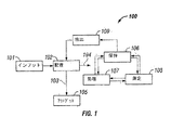


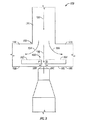
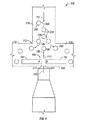

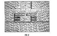


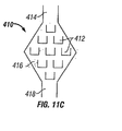
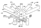


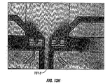


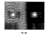
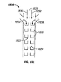

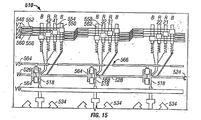


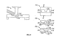
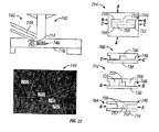


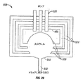


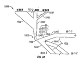


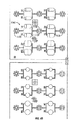


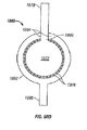
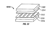

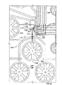


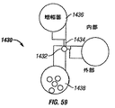


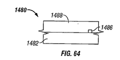


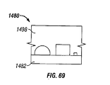
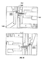


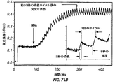

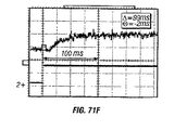


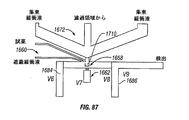
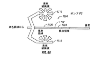


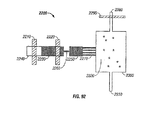


Classifications
-
- C—CHEMISTRY; METALLURGY
- C12—BIOCHEMISTRY; BEER; SPIRITS; WINE; VINEGAR; MICROBIOLOGY; ENZYMOLOGY; MUTATION OR GENETIC ENGINEERING
- C12M—APPARATUS FOR ENZYMOLOGY OR MICROBIOLOGY; APPARATUS FOR CULTURING MICROORGANISMS FOR PRODUCING BIOMASS, FOR GROWING CELLS OR FOR OBTAINING FERMENTATION OR METABOLIC PRODUCTS, i.e. BIOREACTORS OR FERMENTERS
- C12M21/00—Bioreactors or fermenters specially adapted for specific uses
- C12M21/06—Bioreactors or fermenters specially adapted for specific uses for in vitro fertilization
-
- C—CHEMISTRY; METALLURGY
- C12—BIOCHEMISTRY; BEER; SPIRITS; WINE; VINEGAR; MICROBIOLOGY; ENZYMOLOGY; MUTATION OR GENETIC ENGINEERING
- C12M—APPARATUS FOR ENZYMOLOGY OR MICROBIOLOGY; APPARATUS FOR CULTURING MICROORGANISMS FOR PRODUCING BIOMASS, FOR GROWING CELLS OR FOR OBTAINING FERMENTATION OR METABOLIC PRODUCTS, i.e. BIOREACTORS OR FERMENTERS
- C12M1/00—Apparatus for enzymology or microbiology
- C12M1/34—Measuring or testing with condition measuring or sensing means, e.g. colony counters
-
- B—PERFORMING OPERATIONS; TRANSPORTING
- B01—PHYSICAL OR CHEMICAL PROCESSES OR APPARATUS IN GENERAL
- B01L—CHEMICAL OR PHYSICAL LABORATORY APPARATUS FOR GENERAL USE
- B01L3/00—Containers or dishes for laboratory use, e.g. laboratory glassware; Droppers
- B01L3/50—Containers for the purpose of retaining a material to be analysed, e.g. test tubes
- B01L3/502—Containers for the purpose of retaining a material to be analysed, e.g. test tubes with fluid transport, e.g. in multi-compartment structures
- B01L3/5027—Containers for the purpose of retaining a material to be analysed, e.g. test tubes with fluid transport, e.g. in multi-compartment structures by integrated microfluidic structures, i.e. dimensions of channels and chambers are such that surface tension forces are important, e.g. lab-on-a-chip
- B01L3/502738—Containers for the purpose of retaining a material to be analysed, e.g. test tubes with fluid transport, e.g. in multi-compartment structures by integrated microfluidic structures, i.e. dimensions of channels and chambers are such that surface tension forces are important, e.g. lab-on-a-chip characterised by integrated valves
-
- B—PERFORMING OPERATIONS; TRANSPORTING
- B01—PHYSICAL OR CHEMICAL PROCESSES OR APPARATUS IN GENERAL
- B01L—CHEMICAL OR PHYSICAL LABORATORY APPARATUS FOR GENERAL USE
- B01L3/00—Containers or dishes for laboratory use, e.g. laboratory glassware; Droppers
- B01L3/50—Containers for the purpose of retaining a material to be analysed, e.g. test tubes
- B01L3/502—Containers for the purpose of retaining a material to be analysed, e.g. test tubes with fluid transport, e.g. in multi-compartment structures
- B01L3/5027—Containers for the purpose of retaining a material to be analysed, e.g. test tubes with fluid transport, e.g. in multi-compartment structures by integrated microfluidic structures, i.e. dimensions of channels and chambers are such that surface tension forces are important, e.g. lab-on-a-chip
- B01L3/502761—Containers for the purpose of retaining a material to be analysed, e.g. test tubes with fluid transport, e.g. in multi-compartment structures by integrated microfluidic structures, i.e. dimensions of channels and chambers are such that surface tension forces are important, e.g. lab-on-a-chip specially adapted for handling suspended solids or molecules independently from the bulk fluid flow, e.g. for trapping or sorting beads, for physically stretching molecules
-
- C—CHEMISTRY; METALLURGY
- C12—BIOCHEMISTRY; BEER; SPIRITS; WINE; VINEGAR; MICROBIOLOGY; ENZYMOLOGY; MUTATION OR GENETIC ENGINEERING
- C12M—APPARATUS FOR ENZYMOLOGY OR MICROBIOLOGY; APPARATUS FOR CULTURING MICROORGANISMS FOR PRODUCING BIOMASS, FOR GROWING CELLS OR FOR OBTAINING FERMENTATION OR METABOLIC PRODUCTS, i.e. BIOREACTORS OR FERMENTERS
- C12M23/00—Constructional details, e.g. recesses, hinges
- C12M23/02—Form or structure of the vessel
- C12M23/16—Microfluidic devices; Capillary tubes
-
- G—PHYSICS
- G01—MEASURING; TESTING
- G01N—INVESTIGATING OR ANALYSING MATERIALS BY DETERMINING THEIR CHEMICAL OR PHYSICAL PROPERTIES
- G01N33/00—Investigating or analysing materials by specific methods not covered by groups G01N1/00 - G01N31/00
- G01N33/48—Biological material, e.g. blood, urine; Haemocytometers
- G01N33/483—Physical analysis of biological material
- G01N33/4833—Physical analysis of biological material of solid biological material, e.g. tissue samples, cell cultures
-
- G—PHYSICS
- G02—OPTICS
- G02B—OPTICAL ELEMENTS, SYSTEMS OR APPARATUS
- G02B21/00—Microscopes
- G02B21/32—Micromanipulators structurally combined with microscopes
-
- B—PERFORMING OPERATIONS; TRANSPORTING
- B01—PHYSICAL OR CHEMICAL PROCESSES OR APPARATUS IN GENERAL
- B01L—CHEMICAL OR PHYSICAL LABORATORY APPARATUS FOR GENERAL USE
- B01L2200/00—Solutions for specific problems relating to chemical or physical laboratory apparatus
- B01L2200/06—Fluid handling related problems
- B01L2200/0636—Focussing flows, e.g. to laminate flows
-
- B—PERFORMING OPERATIONS; TRANSPORTING
- B01—PHYSICAL OR CHEMICAL PROCESSES OR APPARATUS IN GENERAL
- B01L—CHEMICAL OR PHYSICAL LABORATORY APPARATUS FOR GENERAL USE
- B01L2200/00—Solutions for specific problems relating to chemical or physical laboratory apparatus
- B01L2200/06—Fluid handling related problems
- B01L2200/0647—Handling flowable solids, e.g. microscopic beads, cells, particles
- B01L2200/0652—Sorting or classification of particles or molecules
-
- B—PERFORMING OPERATIONS; TRANSPORTING
- B01—PHYSICAL OR CHEMICAL PROCESSES OR APPARATUS IN GENERAL
- B01L—CHEMICAL OR PHYSICAL LABORATORY APPARATUS FOR GENERAL USE
- B01L2200/00—Solutions for specific problems relating to chemical or physical laboratory apparatus
- B01L2200/06—Fluid handling related problems
- B01L2200/0647—Handling flowable solids, e.g. microscopic beads, cells, particles
- B01L2200/0668—Trapping microscopic beads
-
- B—PERFORMING OPERATIONS; TRANSPORTING
- B01—PHYSICAL OR CHEMICAL PROCESSES OR APPARATUS IN GENERAL
- B01L—CHEMICAL OR PHYSICAL LABORATORY APPARATUS FOR GENERAL USE
- B01L2200/00—Solutions for specific problems relating to chemical or physical laboratory apparatus
- B01L2200/10—Integrating sample preparation and analysis in single entity, e.g. lab-on-a-chip concept
-
- B—PERFORMING OPERATIONS; TRANSPORTING
- B01—PHYSICAL OR CHEMICAL PROCESSES OR APPARATUS IN GENERAL
- B01L—CHEMICAL OR PHYSICAL LABORATORY APPARATUS FOR GENERAL USE
- B01L2200/00—Solutions for specific problems relating to chemical or physical laboratory apparatus
- B01L2200/12—Specific details about manufacturing devices
-
- B—PERFORMING OPERATIONS; TRANSPORTING
- B01—PHYSICAL OR CHEMICAL PROCESSES OR APPARATUS IN GENERAL
- B01L—CHEMICAL OR PHYSICAL LABORATORY APPARATUS FOR GENERAL USE
- B01L2200/00—Solutions for specific problems relating to chemical or physical laboratory apparatus
- B01L2200/16—Reagents, handling or storing thereof
-
- B—PERFORMING OPERATIONS; TRANSPORTING
- B01—PHYSICAL OR CHEMICAL PROCESSES OR APPARATUS IN GENERAL
- B01L—CHEMICAL OR PHYSICAL LABORATORY APPARATUS FOR GENERAL USE
- B01L2300/00—Additional constructional details
- B01L2300/06—Auxiliary integrated devices, integrated components
-
- B—PERFORMING OPERATIONS; TRANSPORTING
- B01—PHYSICAL OR CHEMICAL PROCESSES OR APPARATUS IN GENERAL
- B01L—CHEMICAL OR PHYSICAL LABORATORY APPARATUS FOR GENERAL USE
- B01L2300/00—Additional constructional details
- B01L2300/06—Auxiliary integrated devices, integrated components
- B01L2300/0627—Sensor or part of a sensor is integrated
- B01L2300/0636—Integrated biosensor, microarrays
-
- B—PERFORMING OPERATIONS; TRANSPORTING
- B01—PHYSICAL OR CHEMICAL PROCESSES OR APPARATUS IN GENERAL
- B01L—CHEMICAL OR PHYSICAL LABORATORY APPARATUS FOR GENERAL USE
- B01L2300/00—Additional constructional details
- B01L2300/06—Auxiliary integrated devices, integrated components
- B01L2300/0627—Sensor or part of a sensor is integrated
- B01L2300/0645—Electrodes
-
- B—PERFORMING OPERATIONS; TRANSPORTING
- B01—PHYSICAL OR CHEMICAL PROCESSES OR APPARATUS IN GENERAL
- B01L—CHEMICAL OR PHYSICAL LABORATORY APPARATUS FOR GENERAL USE
- B01L2300/00—Additional constructional details
- B01L2300/06—Auxiliary integrated devices, integrated components
- B01L2300/0681—Filter
-
- B—PERFORMING OPERATIONS; TRANSPORTING
- B01—PHYSICAL OR CHEMICAL PROCESSES OR APPARATUS IN GENERAL
- B01L—CHEMICAL OR PHYSICAL LABORATORY APPARATUS FOR GENERAL USE
- B01L2300/00—Additional constructional details
- B01L2300/08—Geometry, shape and general structure
- B01L2300/0861—Configuration of multiple channels and/or chambers in a single devices
- B01L2300/0867—Multiple inlets and one sample wells, e.g. mixing, dilution
-
- B—PERFORMING OPERATIONS; TRANSPORTING
- B01—PHYSICAL OR CHEMICAL PROCESSES OR APPARATUS IN GENERAL
- B01L—CHEMICAL OR PHYSICAL LABORATORY APPARATUS FOR GENERAL USE
- B01L2300/00—Additional constructional details
- B01L2300/08—Geometry, shape and general structure
- B01L2300/0861—Configuration of multiple channels and/or chambers in a single devices
- B01L2300/087—Multiple sequential chambers
-
- B—PERFORMING OPERATIONS; TRANSPORTING
- B01—PHYSICAL OR CHEMICAL PROCESSES OR APPARATUS IN GENERAL
- B01L—CHEMICAL OR PHYSICAL LABORATORY APPARATUS FOR GENERAL USE
- B01L2300/00—Additional constructional details
- B01L2300/08—Geometry, shape and general structure
- B01L2300/0861—Configuration of multiple channels and/or chambers in a single devices
- B01L2300/088—Channel loops
-
- B—PERFORMING OPERATIONS; TRANSPORTING
- B01—PHYSICAL OR CHEMICAL PROCESSES OR APPARATUS IN GENERAL
- B01L—CHEMICAL OR PHYSICAL LABORATORY APPARATUS FOR GENERAL USE
- B01L2300/00—Additional constructional details
- B01L2300/08—Geometry, shape and general structure
- B01L2300/0887—Laminated structure
-
- B—PERFORMING OPERATIONS; TRANSPORTING
- B01—PHYSICAL OR CHEMICAL PROCESSES OR APPARATUS IN GENERAL
- B01L—CHEMICAL OR PHYSICAL LABORATORY APPARATUS FOR GENERAL USE
- B01L2300/00—Additional constructional details
- B01L2300/08—Geometry, shape and general structure
- B01L2300/0893—Geometry, shape and general structure having a very large number of wells, microfabricated wells
-
- B—PERFORMING OPERATIONS; TRANSPORTING
- B01—PHYSICAL OR CHEMICAL PROCESSES OR APPARATUS IN GENERAL
- B01L—CHEMICAL OR PHYSICAL LABORATORY APPARATUS FOR GENERAL USE
- B01L2300/00—Additional constructional details
- B01L2300/12—Specific details about materials
- B01L2300/123—Flexible; Elastomeric
-
- B—PERFORMING OPERATIONS; TRANSPORTING
- B01—PHYSICAL OR CHEMICAL PROCESSES OR APPARATUS IN GENERAL
- B01L—CHEMICAL OR PHYSICAL LABORATORY APPARATUS FOR GENERAL USE
- B01L2400/00—Moving or stopping fluids
- B01L2400/04—Moving fluids with specific forces or mechanical means
- B01L2400/0403—Moving fluids with specific forces or mechanical means specific forces
- B01L2400/0409—Moving fluids with specific forces or mechanical means specific forces centrifugal forces
-
- B—PERFORMING OPERATIONS; TRANSPORTING
- B01—PHYSICAL OR CHEMICAL PROCESSES OR APPARATUS IN GENERAL
- B01L—CHEMICAL OR PHYSICAL LABORATORY APPARATUS FOR GENERAL USE
- B01L2400/00—Moving or stopping fluids
- B01L2400/04—Moving fluids with specific forces or mechanical means
- B01L2400/0403—Moving fluids with specific forces or mechanical means specific forces
- B01L2400/0415—Moving fluids with specific forces or mechanical means specific forces electrical forces, e.g. electrokinetic
-
- B—PERFORMING OPERATIONS; TRANSPORTING
- B01—PHYSICAL OR CHEMICAL PROCESSES OR APPARATUS IN GENERAL
- B01L—CHEMICAL OR PHYSICAL LABORATORY APPARATUS FOR GENERAL USE
- B01L2400/00—Moving or stopping fluids
- B01L2400/04—Moving fluids with specific forces or mechanical means
- B01L2400/0475—Moving fluids with specific forces or mechanical means specific mechanical means and fluid pressure
- B01L2400/0481—Moving fluids with specific forces or mechanical means specific mechanical means and fluid pressure squeezing of channels or chambers
-
- B—PERFORMING OPERATIONS; TRANSPORTING
- B01—PHYSICAL OR CHEMICAL PROCESSES OR APPARATUS IN GENERAL
- B01L—CHEMICAL OR PHYSICAL LABORATORY APPARATUS FOR GENERAL USE
- B01L2400/00—Moving or stopping fluids
- B01L2400/06—Valves, specific forms thereof
- B01L2400/0622—Valves, specific forms thereof distribution valves, valves having multiple inlets and/or outlets, e.g. metering valves, multi-way valves
-
- B—PERFORMING OPERATIONS; TRANSPORTING
- B01—PHYSICAL OR CHEMICAL PROCESSES OR APPARATUS IN GENERAL
- B01L—CHEMICAL OR PHYSICAL LABORATORY APPARATUS FOR GENERAL USE
- B01L2400/00—Moving or stopping fluids
- B01L2400/06—Valves, specific forms thereof
- B01L2400/0633—Valves, specific forms thereof with moving parts
- B01L2400/0655—Valves, specific forms thereof with moving parts pinch valves
-
- B—PERFORMING OPERATIONS; TRANSPORTING
- B01—PHYSICAL OR CHEMICAL PROCESSES OR APPARATUS IN GENERAL
- B01L—CHEMICAL OR PHYSICAL LABORATORY APPARATUS FOR GENERAL USE
- B01L3/00—Containers or dishes for laboratory use, e.g. laboratory glassware; Droppers
- B01L3/50—Containers for the purpose of retaining a material to be analysed, e.g. test tubes
- B01L3/502—Containers for the purpose of retaining a material to be analysed, e.g. test tubes with fluid transport, e.g. in multi-compartment structures
- B01L3/5027—Containers for the purpose of retaining a material to be analysed, e.g. test tubes with fluid transport, e.g. in multi-compartment structures by integrated microfluidic structures, i.e. dimensions of channels and chambers are such that surface tension forces are important, e.g. lab-on-a-chip
- B01L3/502746—Containers for the purpose of retaining a material to be analysed, e.g. test tubes with fluid transport, e.g. in multi-compartment structures by integrated microfluidic structures, i.e. dimensions of channels and chambers are such that surface tension forces are important, e.g. lab-on-a-chip characterised by the means for controlling flow resistance, e.g. flow controllers, baffles
-
- B—PERFORMING OPERATIONS; TRANSPORTING
- B01—PHYSICAL OR CHEMICAL PROCESSES OR APPARATUS IN GENERAL
- B01L—CHEMICAL OR PHYSICAL LABORATORY APPARATUS FOR GENERAL USE
- B01L3/00—Containers or dishes for laboratory use, e.g. laboratory glassware; Droppers
- B01L3/50—Containers for the purpose of retaining a material to be analysed, e.g. test tubes
- B01L3/502—Containers for the purpose of retaining a material to be analysed, e.g. test tubes with fluid transport, e.g. in multi-compartment structures
- B01L3/5027—Containers for the purpose of retaining a material to be analysed, e.g. test tubes with fluid transport, e.g. in multi-compartment structures by integrated microfluidic structures, i.e. dimensions of channels and chambers are such that surface tension forces are important, e.g. lab-on-a-chip
- B01L3/502753—Containers for the purpose of retaining a material to be analysed, e.g. test tubes with fluid transport, e.g. in multi-compartment structures by integrated microfluidic structures, i.e. dimensions of channels and chambers are such that surface tension forces are important, e.g. lab-on-a-chip characterised by bulk separation arrangements on lab-on-a-chip devices, e.g. for filtration or centrifugation
-
- G—PHYSICS
- G01—MEASURING; TESTING
- G01N—INVESTIGATING OR ANALYSING MATERIALS BY DETERMINING THEIR CHEMICAL OR PHYSICAL PROPERTIES
- G01N15/00—Investigating characteristics of particles; Investigating permeability, pore-volume, or surface-area of porous materials
- G01N15/10—Investigating individual particles
- G01N15/14—Electro-optical investigation, e.g. flow cytometers
- G01N15/1484—Electro-optical investigation, e.g. flow cytometers microstructural devices
-
- G01N15/149—
-
- G01N2015/016—
-
- G—PHYSICS
- G01—MEASURING; TESTING
- G01N—INVESTIGATING OR ANALYSING MATERIALS BY DETERMINING THEIR CHEMICAL OR PHYSICAL PROPERTIES
- G01N15/00—Investigating characteristics of particles; Investigating permeability, pore-volume, or surface-area of porous materials
- G01N15/02—Investigating particle size or size distribution
- G01N2015/0288—Sorting the particles
-
- G—PHYSICS
- G01—MEASURING; TESTING
- G01N—INVESTIGATING OR ANALYSING MATERIALS BY DETERMINING THEIR CHEMICAL OR PHYSICAL PROPERTIES
- G01N15/00—Investigating characteristics of particles; Investigating permeability, pore-volume, or surface-area of porous materials
- G01N15/10—Investigating individual particles
- G01N15/14—Electro-optical investigation, e.g. flow cytometers
- G01N2015/1493—Particle size
Abstract
Description
(優先権)
本出願は、米国特許法第119条(e)項に基づいて、米国仮特許出願第60/369,538号(2002年4月1日出願)および同第60/378,464号(2002年5月6日出願)(これらはともに、全ての目的ならびに本明細書中およびその特許出願に記載される目的のために、その全体が本明細書中に参考として援用される)に対する優先権の利益を主張する。本出願はさらに、米国特許法第120条に基づいて、非仮特許出願(Chouらによる2003年3月31日出願の、標題「MicrofluidicParticle−Analysis Systems」(代理人整理番号139F.310US)の一部継続出願(これは、全ての目的のために、本明細書中に参考として援用される)として、優先権を主張する。
(priority)
This application is based on 35 USC 119 (e), US Provisional Patent Application Nos. 60 / 369,538 (filed April 1, 2002) and 60 / 378,464 (2002). (Filed May 6), both of which are incorporated by reference herein in their entirety for all purposes and purposes described herein and in their patent applications. Insist on profit. This application is further based on
(特許出願に対する引用)
本出願は、米国特許出願第09/605,520号(2000年6月27日出願);同第09/724,784号(2000年11月28日出願);同第09/724,967号(2000年11月28日出願);同第09/796,378号(2001年2月28日出願);同第09/796,666号(2001年2月28日出願);同第09/796,871号(2001年2月28日出願);同第09/826,583号(2001年4月6日出願);および同第09/724,784号(2001年11月28日出願、標題「MICROFABRICATEDELASTOMERIC VALVE AND PUMP SYSTEMS」および発明者、Marc A.Unger、Hou−Pu Chou、Todd A. Thorsen、AxelScherer、Stephen R. Quake、Jian Liu、Mark L. Adams、およびCarl L. Hansen)を全ての目的で、その全体を本明細書中に参考として援用する。
(Citation for patent application)
No. 09 / 605,520 (filed Jun. 27, 2000); 09 / 724,784 (filed Nov. 28, 2000); 09 / 724,967 (Filed on Nov. 28, 2000); 09 / 796,378 (filed on Feb. 28, 2001); 09 / 796,666 (filed on Feb. 28, 2001); No. 796,871 (filed Feb. 28, 2001); 09 / 826,583 (filed Apr. 6, 2001); and 09 / 724,784 (filed Nov. 28, 2001); The title “MICROFABRICATEDELASTOMERIC VALVE AND PUMP SYSTEMS” and the inventors, Marc A. Unger, Hou-Pu Chou, Todd A. Thorsen AxelScherer, Stephen R. Quake, Jian Liu, in Mark L. Adams, and Carl L. Hansen) all of the objects, which are incorporated by reference herein in its entirety.
(他の文献に対する引用)
本出願は、以下の刊行物を、全ての目的で本明細書中に参考として援用する:Joe SambrookおよびDavid Russell,Molecular Cloning:ALaboratory Manual(第3版、2000);ならびにR.Ian Freshney,Culture of Animal Cells:A Manualof Basic Technique(第4版、2000)。
(Citations to other documents)
This application incorporates the following publications by reference for all purposes: Joe Sambrook and David Russell, Molecular Cloning: Laboratory Manual (3rd edition, 2000); Ian Freshney, Culture of Animal Cells: A Manual of Basic Techniques (4th edition, 2000).
(発明の分野)
本発明は、粒子の操作および/または検出のためのシステムに関する。より具体的には、本発明は、粒子(例えば、細胞および/またはビーズ)の操作および/または検出のための微小流体システムに関する。
(Field of Invention)
The present invention relates to a system for particle manipulation and / or detection. More specifically, the present invention relates to microfluidic systems for manipulation and / or detection of particles (eg, cells and / or beads).
(発明の背景)
生物学的システムが分子分析および細胞分析を行う能力は、過去30年間で爆発的に成長した。特に、分子技術および細胞技術(例えば、DNA配列決定、遺伝子クローニング、モノクローナル抗体生成、細胞トランスフェクション、増幅技術(例えば、PCR)、およびトランスジェニック動物の成立)の出現および洗練は、この爆発的な成長を刺激した。これらの技術は、圧倒的多数の同定遺伝子、コードタンパク質、操作された細胞型、ならびにこれらの遺伝子、タンパク質、および細胞型を研究するためのアッセイを生み出した。サンプル、試薬、およびアッセイのあり得る組み合わせの数がほとんど計算できないほどになるにつれて、特に妥当な時間的制限および金銭的制限内で、この複雑性を理解し始めるためにも、新規なアプローチが必要なことがますます明らかになってきている。
(Background of the Invention)
The ability of biological systems to perform molecular and cellular analysis has grown explosively over the last 30 years. In particular, the emergence and sophistication of molecular and cellular technologies (eg, DNA sequencing, gene cloning, monoclonal antibody generation, cell transfection, amplification techniques (eg, PCR), and the establishment of transgenic animals) are explosive. Stimulated growth. These techniques have generated an overwhelming number of identified genes, encoded proteins, engineered cell types, and assays for studying these genes, proteins, and cell types. As the number of possible combinations of samples, reagents, and assays becomes nearly uncalculatable, new approaches are needed to begin to understand this complexity, especially within reasonable time and monetary limits More and more is becoming clearer.
これらの困難性に対する1つのアプローチは、アッセイのスケールを縮小することであった。従って、実質的な取り組みは、アッセイ方法および高密度マイクロタイタープレート用器具を開発することに関していた。しかし、高密度マイクロタイタープレートにおける非常に少ないアッセイ容積(特に細胞を用いるアッセイ)は、多くの欠点があり得る。例えば、細胞は、ウェルから容易になくなり得、急速な流体の蒸発による不都合があり得、ウェルの近くで汚染があり得、そしてさらなる分析または培養のためにウェルから効率的に回収することが困難であり得る。従って、細胞および他の小粒子(例えば、ビーズ)を少量で効率的に操作および分析し得るシステムが必要である。 One approach to these difficulties has been to reduce the scale of the assay. Thus, substantial efforts have been associated with developing assay methods and high density microtiter plate instruments. However, very small assay volumes (especially assays using cells) in high density microtiter plates can have many drawbacks. For example, cells can easily disappear from the well, can be inconvenient due to rapid fluid evaporation, can be contaminated near the well, and difficult to efficiently recover from the well for further analysis or culture It can be. Therefore, there is a need for a system that can efficiently manipulate and analyze cells and other small particles (eg, beads) in small amounts.
(発明の要旨)
本発明は、粒子(例えば、細胞および/またはビーズ)の微小流体操作および/または検出のためのシステム(装置を含む)、方法、およびキットを提供する。
より特定すれば、本願発明は以下の項目に関し得る。
(項目1)
粒子を処理するための微小流体デバイスであって、上記デバイスが、以下:
(a)粒子を含む流体サンプルを導入するためのインプットメカニズム;
(b)上記インプットメカニズムと流体連絡している微小流体通路;
(c)上記微小流体通路と流体連絡している配置メカニズムであって、上記配置メカニズムが、上記流体サンプル中に含まれる上記粒子を上記微小流体通路中に配置させるための配置メカニズム;
(d)配置手段により配置されている上記粒子を保持するための保持メカニズム;
(e)上記保持メカニズム中に保持されている上記粒子を選択的に処理して処理応答を生じるための、上記保持メカニズムと連絡している処理メカニズム;および
(f)上記粒子の処理応答を、存在する場合、測定するための測定メカニズム
を備える、デバイス。
(項目2)
項目1に記載の微小流体デバイスであって、上記デバイスが、上記粒子を上記保持メカニズムから放出するための放出メカニズムをさらに備える、デバイス。
(項目3)
項目2に記載の微小流体デバイスであって、上記デバイスが、上記粒子を上記微小流体デバイスからアウトプットするためのアウトプットメカニズムをさらに備える、デバイス。
(項目4)
項目2に記載の微小流体デバイスであって、上記デバイスが、上記粒子を培養するための培養メカニズムをさらに備える、デバイス。
(項目5)
項目1に記載の微小流体デバイスであって、上記デバイスが、上記サンプル流体または他の流体の流量または流路の局面を決定するためのコントロールメカニズムをさらに備える、デバイス。
(項目6)
項目5に記載の微小流体デバイスであって、上記コントロールメカニズムが、上記微小流体通路と連絡しているバルブである、デバイス。
(項目7)
項目6に記載の微小流体デバイスであって、上記微小流体デバイスが、多層エラストマーブロックから形成され、上記バルブが、上記エラストマーブロック中のエラストマー膜から形成される、デバイス。
(項目8)
項目6に記載の微小流体デバイスであって、上記コントロールメカニズムが、上記微小流体通路と連絡しているポンプである、デバイス。
(項目9)
項目8に記載の微小流体デバイスであって、上記微小流体デバイスが、多層エラストマーブロックから形成され、上記ポンプが、上記エラストマーブロック中のエラストマー膜から形成される、デバイス。
(項目10)
項目1に記載の微小流体デバイスであって、上記微小流体デバイスが、流体層中の上記微小流体通路中に偏向可能なエラストマー膜を有するコントロール層を有する多層エラストマーブロックを備え、上記微小流体通路中の流体の流速または流路を決定する、デバイス。
(項目11)
項目1に記載の微小流体デバイスであって、上記微小流体デバイスが、エラストマー、ポリジメチルシロキサン、プラスチック、ポリスチレン、ポリプロピレン、ポリカーボネート、ガラス、セラミック、シリコン、ゾルゲル、金属、メタロイド、金属酸化物、生物学的ポリマー、これらの混合物、粒子、タンパク質、ゼラチン、ポリリシン、血清アルブミン、コラーゲン、核酸、および微生物からなる群から選択される物質を含む層を含む、デバイス。
(項目12)
項目1に記載の微小流体デバイスであって、上記微小流体通路が、約500マイクロメートル幅未満である、デバイス。
(項目13)
項目1に記載の微小流体デバイスであって、上記微小流体通路が、連結または分岐にて上記微小流体通路に結合する隣接する通路をさらに備え、上記隣接する通路が、入口通路、出口通路、粒子通路、試薬通路、および廃棄物通路からなる群から選択されている、デバイス。
(項目14)
項目13に記載の微小流体デバイスであって、上記隣接する通路が、行き止まりの通路である、デバイス。
(項目15)
項目13に記載の微小流体デバイスであって、上記デバイスが、上記粒子を操作する上記隣接する通路をさらに備える、デバイス。
(項目16)
項目15に記載の微小流体デバイスであって、上記粒子操作が、配置、分類、保持、処理、検出、増殖、蓄積、混合および放出の群から選択される、デバイス。
(項目17)
項目1に記載の微小流体デバイスであって、上記粒子が、細胞、真核生物細胞、原核生物細胞、植物細胞、動物細胞、ハイブリドーマ細胞、細菌細胞、酵母細胞、ウイルス、オルガネラ、ビーズおよび小胞からなる群から選択される、デバイス。
(項目18)
項目17に記載の微小流体デバイスであって、上記粒子が、複数の粒子または粒子の集合体である、デバイス。
(項目19)
項目18に記載の微小流体デバイスであって、上記複数の粒子が、異なる粒子を含む複合体混合物である、デバイス。
(項目20)
項目19に記載の微小流体デバイスであって、上記異なる粒子を含む複合体混合物が、全血または血清または体液である、デバイス。
(項目21)
項目1に記載の微小流体デバイスであって、上記粒子が、卵または胎芽である、デバイス。
(項目22)
項目1に記載の微小流体デバイスであって、上記インプットメカニズムが、上記微小流体通路と流体連絡している、容器または壁である、デバイス。
(項目23)
項目22に記載の微小流体デバイスであって、上記インプットメカニズムが、上記微小流体通路により規定される容積よりも大きな容積を有する、デバイス。
(項目24)
項目1に記載の微小流体デバイスであって、上記デバイスが、上記インプットメカニズムと連絡しているまたは上記インプットメカニズム上で作動している促進メカニズムをさらに備える、デバイス。
(項目25)
項目24に記載の微小流体デバイスであって、上記促進メカニズムが、重力、流体圧、遠心圧、ポンプ圧、および流体陰圧からなる群から選択される、デバイス。
(項目26)
項目1に記載の微小流体デバイスであって、上記配置メカニズムが、直接配置メカニズムまたは間接配置メカニズムである、デバイス。
(項目27)
項目26に記載の微小流体デバイスであって、上記直接配置メカニズムが、光学、電気、磁気および重力からなる群から選択される力である、デバイス。
(項目28)
項目27に記載の微小流体デバイスであって、上記電気的力が、電気泳動、電気浸透、および誘電泳動からなる群から選択される、デバイス。
(項目29)
項目26に記載の微小流体デバイスであって、上記間接配置メカニズムが、縦間接配置メカニズムまたは横間接配置メカニズムである、デバイス。
(項目30)
項目29に記載の微小流体デバイスであって、上記間接配置メカニズムが、上記微小流体デバイスと結合したポンプまたはバルブにより促進される、デバイス。
(項目31)
項目29に記載の微小流体デバイスであって、上記横間接配置メカニズムが、通路連結、減少した流体流の左右に配置される領域、またはチャネル屈曲での流体流により促進される、デバイス。
(項目32)
項目31に記載の微小流体デバイスであって、上記通路連結が、統合または分割している、デバイス。
(項目33)
項目29に記載の微小流体デバイスであって、上記横配置メカニズムが、層流に基づく横配置手段である、デバイス。
(項目34)
項目29に記載の微小流体デバイスであって、上記横間接配置メカニズムが、推計学的横配置メカニズムである、デバイス。
(項目35)
項目34に記載の微小流体デバイスであって、上記推計学的横配置メカニズムが、上記サンプル流体中の上記粒子の主な流れの領域から減少した流れの領域への左右の分離により、粒子の集団から上記粒子を無作為に選択する、デバイス。
(項目36)
項目29に記載の微小流体デバイスであって、上記横間接配置メカニズムが、遠心力に基づく横配置メカニズムである、デバイス。
(項目37)
項目1に記載の微小流体デバイスであって、上記保持メカニズムが、上記微小流体デバイス中の予め選択された領域で上記粒子を選択的に保持する、デバイス。
(項目38)
項目37に記載の微小流体デバイスであって、上記保持メカニズムが、上記配置メカニズムにより引き起こされる力に打ち勝つまたは打ち消すことにより上記粒子を保持する、デバイス。
(項目39)
項目1に記載の微小流体デバイスであって、上記保持メカニズムが、トラップまたは障壁に基づく保持メカニズムである、デバイス。
(項目40)
項目39に記載の微小流体デバイスであって、上記障壁に基づく保持メカニズムが、上記微小流体通路中のまたは上記微小流体通路に隣接する上記粒子の縦移動を制限する、デバイス。
(項目41)
項目38に記載の微小流体デバイスであって、上記保持メカニズムが、固定してまたは一時的に、上記微小流体通路中にまたは上記微小流体通路に隣接して延び、上記粒子の縦移動を制限する突起部である、デバイス。
(項目42)
項目26に記載の微小流体デバイスであって、上記直接配置メカニズムが、化学的保持メカニズムである、デバイス。
(項目43)
項目42に記載の微小流体デバイスであって、上記化学的保持メカニズムが、上記粒子と上記保持メカニズムとの間の特異的な親和力に基づく、デバイス。
(項目44)
項目1に記載の微小流体デバイスであって、上記処理メカニズムが、流体媒介メカニズムまたは非流体媒介メカニズムである、デバイス。
(項目45)
項目1に記載の微小流体デバイスであって、上記処理メカニズムが、上記粒子を試薬または物理的条件に曝す、デバイス。
(項目46)
項目45に記載の微小流体デバイスであって、上記試薬が、化学的変調器、生物学的変調器、アゴニスト、アンタゴニスト、ホルモン、リガンド、低分子、ペプチド、タンパク質、炭水化物、脂質、レセプター、栄養素、毒素、薬物、化学物質、化合物、イオン、ポリマー、核酸、物質、複合体、混合物、集合体、色素、染料、蛍光色素、検出剤、アッセイ剤、基質、基質阻害剤、抗体、標識物質、および生物学的粒子からなる群から選択される、デバイス。
(項目47)
項目46に記載の微小流体デバイスであって、上記試薬が、上記粒子を引きつけるまたは反発する、デバイス。
(項目48)
項目45に記載の微小流体デバイスであって、上記試薬が、細胞粒子増殖を誘発または阻害する、デバイス。
(項目49)
項目45に記載の微小流体デバイスであって、上記試薬が、細胞傷害性である、デバイス。
(項目50)
項目44に記載の微小流体デバイスであって、上記流体媒介メカニズムが、流体処理をさらに備え、そして上記粒子が、上記流体処理に導入される、デバイス。
(項目51)
項目44に記載の微小流体デバイスであって、上記流体媒介メカニズムが、上記配置メカニズムの機能と結合して機能する、デバイス。
(項目52)
項目51に記載の微小流体デバイスであって、上記配置メカニズムが、上記粒子を、上記流体媒介メカニズム中におよび上記流体媒介メカニズム外に移動させ、上記粒子の処理流体への曝露を調節する、横配置メカニズムである、デバイス。
(項目53)
項目45に記載の微小流体デバイスであって、上記物理的条件が、熱、光、放射能、亜原子粒子、電場、磁場、圧力、音波圧、重力、および微重力からなる群から選択される、デバイス。
(項目54)
項目1に記載の微小流体デバイスであって、上記測定メカニズムが、上記粒子の特性または上記粒子により引き起こされる特性を検出する上記微小流体デバイスと結合される検出器である、デバイス。
(項目55)
項目54に記載の微小流体デバイスであって、上記検出器が、分光器、電気的センサー、流体力学的センサー、画像化システム、および光子検出器からなる群から選択される、デバイス。
(項目56)
項目54に記載の微小流体デバイスであって、上記検出器が、複数のバルブを検出する、デバイス。
(項目57)
項目54に記載の微小流体デバイスであって、上記検出器が、時間に依存しない様式、時間依存様式、および平均化様式からなる群から選択される検出様式を使用する、デバイス。
(項目58)
項目54に記載の微小流体デバイスであって、上記検出器が、吸収、ルミネセンス、光ルミネセンス、化学ルミネセンス、エレクトロルミネセンス、磁気共鳴、原子核共鳴、電子スピン共鳴、散乱、電子散乱、光散乱、中性子散乱、回折、円偏光二色性、施光度、蛍光強度、蛍光共鳴エネルギー移動、蛍光極性、蛍光寿命、全内部反射蛍光、蛍光相関分光学、光退色後の蛍光回復、蛍光活性化細胞分類および燐光性からなる群から選択される型の生じるシグナルを検出する、分光学的検出器である、デバイス。
(項目59)
項目54に記載の微小流体デバイスであって、上記検出器が、電流、電圧、抵抗、静電容量、および電力から選択されるシグナルを検出し得る、電気的検出器である、デバイス。
(項目60)
項目54に記載の微小流体デバイスであって、上記検出器は、上記粒子と流体、別の粒子または上記微小流体通路との流体力学的相互作用を検出する、流体力学的検出器である、デバイス。
(項目61)
項目60に記載の微小流体デバイスであって、上記相互作用が、クロマトグラフィー、沈殿、粘度計、電気泳動からなる群から選択される流体力学的相互作用を含んだ、デバイス。
(項目62)
項目54に記載の微小流体デバイスであって、上記検出器が、上記粒子の画像を作り出し、そして分析するための画像化検出器である、デバイス。
(項目63)
項目54に記載の微小流体デバイスであって、上記検出器が、上記粒子により生じる生物学的応答を検出する、デバイス。
(項目64)
項目63に記載の微小流体デバイスであって、上記生物学的応答が、化学走性、細胞間相互作用、老化、アポトーシス、増殖、分化、形態学的変化、pH変化、およびカルシウム摂取からなる群から選択される、デバイス。
(項目65)
項目1に記載の微小流体デバイスであって、上記デバイスが、検出部位をさらに備え、上記粒子または上記粒子の生成物が、上記検出器により検出される、デバイス。
(項目66)
項目65に記載の微小流体デバイスであって、上記検出部位が、上記微小粒体デバイス中にある、デバイス。
(項目67)
項目65に記載の微小流体デバイスであって、上記検出部位が、上記微小流体デバイスに対して外部に位置される、デバイス。
(項目68)
項目54に記載の微小流体デバイスであって、上記検出器が、上記粒子の特性を直接的または間接的に検出し、上記特性が、粒子固有性、粒子数、粒子濃度、組成物、構造、配列、活性、分子特性、形態学、表現型、遺伝子型、増殖、アポトーシス、壊死、溶解、生存率/死亡率、細胞周期での位置、シグナル経路の活性、分化、転写活性、基質結合、細胞−細胞相互作用、翻訳活性、複製活性、形質転換、熱ショック応答、運動性、拡散、膜完全性、化学走性、および神経突起生長からなる群から選択されている、デバイス。
(項目69)
項目2に記載の微小流体デバイスであって、上記放出メカニズムが、上記保持メカニズムにより引き起こされる保持力を除去することにより作動する、デバイス。
(項目70)
項目2に記載の微小流体デバイスであって、上記放出メカニズムが、上記保持メカニズムにより引き起こされる保持力に打ち勝つことにより作動する、デバイス。
(項目71)
項目2に記載の微小流体デバイスであって、上記放出メカニズムが、上記保持メカニズムにより引き起こされる保持力に無力にさせることにより作動する、デバイス。
(項目72)
項目2に記載の微小流体デバイスであって、上記粒子を上記微小流体デバイス内または上記微小流体デバイスの外部の別の領域に向ける工程をさらに包含する、デバイス。
(項目73)
項目72に記載の微小流体デバイスであって、上記別の領域が、第2の配置メカニズム、第2の検出メカニズム、第2の保持メカニズム、およびアウトプットメカニズムからなる群から選択される、デバイス。
(項目74)
項目73に記載の微小流体デバイスであって、上記第2の保持メカニズムが、細胞培養チャンバである、デバイス。
(項目75)
項目3に記載の微小流体デバイスであって、上記微小流体デバイスが、内部シンクおよび外部シンク、廃棄部位、収集部位、細胞増殖チャンバ、ならびに外部細胞培養プレートからなる群から選択される位置に上記粒子をアウトプットする、上記アウトプットメカニズムをさらに備える、デバイス。
(項目76)
細胞を試薬に浸み込ませるための方法であって、上記方法が、以下の工程:
(a)微小流体デバイスを提供する工程であって、上記デバイスが、以下:
(i)細胞増殖チャンバ
細胞入口が上記チャンバと連絡しており、上記細胞入口が上記細胞入口を通り上記チャンバ中への流体流をバルブで調節する上記細胞入口と作動可能に連絡しているバルブを有し、入口バルブが開いている場合、細胞が上記細胞入口を通り上記チャンバ中に通り得、しかし上記入口バルブが閉じている場合、上記細胞が、上記細胞入口を通ることが出来ない、細胞増殖チャンバ;および
(ii)上記チャンバ中に上記試薬をインプットするための試薬入口であって、上記試薬入口が、上記試薬を通り上記チャンバ中への流体流をバルブ調節するための上記試薬入口と作動可能に連絡している試薬バルブを有し、上記入口または上記チャンバが、上記チャンバ中の上記細胞を保持するための保持メカニズムを有する一方、上記試薬バルブが開いている場合、上記試薬の上記チャンバ中への流れを可能にする、試薬入口を有し;
上記細胞が上記チャンバ中に装填される場合、上記細胞バルブが閉まり、上記細胞が上記チャンバ中に保持される一方、上記試薬バルブは、開きおよび閉まっている、工程;
(b)上記細胞入口バルブを開き、かつ上記細胞を上記チャンバ中に導入する工程;
(c)上記細胞入口バルブを閉める工程;
(d)上記試薬バルブを開き、上記試薬を上記チャンバ中に導入する工程;
(e)上記試薬を上記チャンバ中に導入する一方、上記細胞を上記チャンバ内に保持し、それにより上記細胞を上記試薬に浸み込ませる工程
を包含する、方法。
(項目77)
粒子を処理するための方法であって、上記方法が、以下の工程:
(i)微小流体デバイスを提供する工程であって、上記微小流体デバイスが、以下:
(a)粒子を含む流体サンプルを導入するためのインプットメカニズム;
(b)上記インプットメカニズムと流体連絡している微小流体通路;
(c)上記微小流体通路と流体連絡している配置メカニズムであって、上記配置メカニズムが、上記流体サンプル中に含まれる上記粒子を上記微小流体通路中に配置させるための配置メカニズム;
(d)配置手段により配置されている上記粒子を保持するための保持メカニズム;
(e)上記保持メカニズム中に保持されている上記粒子を選択的に処理して処理応答を生じるための上記保持メカニズムと連絡している処理メカニズム;および
(f)上記粒子の処理応答を、存在する場合、測定するための測定メカニズム
を備える、工程;
(ii)上記粒子を含むサンプル流体を上記インプットメカニズム中に導入する工程;
(iii)上記粒子を上記配置メカニズムを用いて配置させ、その結果、上記粒子が、上記保持メカニズムによって保持可能である、工程;
(iv)上記粒子を上記保持メカニズムを用いて保持する、工程;
(v)上記粒子を上記処理メカニズムにより上記処理に曝露する、工程;
(vi)上記処理への曝露の際に上記粒子により直接または間接で引き起こされる上記処理応答を測定する工程
を包含する、方法。
(項目78)
項目77に記載の方法であって、上記微小流体デバイスが、上記粒子を上記保持メカニズムから放出するための放出メカニズムをさらに備え、上記方法が、上記粒子を上記保持メカニズムから放出する工程をさらに包含する、方法。
(項目79)
項目78に記載の方法であって、上記微小流体デバイスが、上記粒子を上記微小流体デバイスからアウトプットするためのアウトプットメカニズムをさらに備え、上記方法が、上記粒子を上記微小流体デバイスから上記アウトプットメカニズムによりアウトプットする工程をさらに包含する、方法。
(項目80)
項目78に記載の方法であって、上記微小流体デバイスが、上記粒子を培養するための細胞培養メカニズムをさらに備え、上記方法が、上記粒子を上記細胞培養メカニズム中で培養する工程をさらに包含する、方法。
(項目81)
項目77に記載の方法であって、上記微小流体デバイスが、上記サンプル流体または他の流体の流量または流路の局面を決定するためのコントロールメカニズムをさらに備え、そして上記方法が、上記サンプル流体または他の流体の流速または流路を上記コントロールメカニズムにより決定する工程をさらに包含する、方法。
(項目82)
項目81に記載の方法であって、上記コントロールメカニズムが、上記微小流体通路と連絡しているバルブであり、そして上記方法が、上記サンプル流体または他の流体を上記バルブで調節する工程をさらに包含する、方法。
(項目83)
項目82に記載の微小流体デバイスであって、上記微小流体デバイスが、多層エラストマーブロックから形成され、そして上記バルブが、上記エラストマーブロック中のエラストマー膜から形成され、そして上記バルブ調節が、上記エラストマー膜を上記微小流体通路中に偏向させることにより起こる、デバイス。
(項目84)
項目82に記載の方法であって、上記コントロールメカニズムが、上記微小流体通路と連絡しているポンプであり、そして上記サンプル流体の流量または流路の上記決定が、上記ポンプの作動により起こる、方法。
(項目85)
項目84に記載の方法であって、上記微小流体デバイスが、多層エラストマーブロックから形成され、上記ポンプが、上記エラストマーブロック中のエラストマー膜から形成され、そして上記ポンプが、一連のエラストマー膜を、選択された配列における上記微小流体通路中に偏向させることにより作動させる、方法。
(項目86)
項目77に記載の方法であって、上記微小流体デバイスが、流体層中の上記微小流体通路中に偏向可能なエラストマー膜を有するコントロール層を有する多層エラストマーブロックを備え、上記微小流体通路中の流体の流速または流路を選択的に決定する、方法。
(項目87)
項目77に記載の方法であって、上記微小流体通路が、連結または分岐にて上記微小流体通路に結合する隣接する通路をさらに備え、上記隣接する通路が、入口通路、出口通路、粒子通路、試薬通路、および廃棄物通路からなる群から選択されており、そして上記方法が、上記隣接する通路に対して上記粒子の通路を選択的に決定する工程をさらに包含する、方法。
(項目88)
項目87に記載の方法であって、上記隣接する通路が、行き止まりの通路であり、そして上記選択的に決定する工程が、上記サンプル流体を上記行き止まりの通路中に導入する工程を包含し、上記サンプル流体が、上記行き止まりの通路における気体(存在する場合)と置換して、上記行き止まりの通路を上記サンプル流体で満たす、方法。
(項目89)
項目87に記載の方法であって、上記方法が、上記粒子を操作する上記隣接する通路をさらに備える、方法。
(項目90)
項目89に記載の方法であって、上記粒子操作が、上記粒子を配置、分類、処理、検出、増殖、蓄積、混合または放出のいずれかに加えて上記粒子を保持する工程を包含する、方法。
(項目91)
項目77に記載の方法であって、上記粒子が、細胞、真核生物細胞、原核生物細胞、植物細胞、動物細胞、ハイブリドーマ細胞、細菌細胞、酵母細胞、ウイルス、オルガネラ、ビーズおよび小胞からなる群から選択され、上記処理工程が、上記粒子を処理する、方法。
(項目92)
項目91に記載の方法であって、上記粒子が、複数の粒子または粒子の集合体であり、上記方法が、所望される粒子を上記複数の粒子から分類および分離または単離する分類工程をさらに包含し、そして上記処理工程が、上記分離されたまたは単離された粒子を処理する、方法。
(項目93)
項目92に記載の方法であって、上記複数の粒子が、異なる粒子を含む複合体混合物であり、そして上記分類工程が、少なくとも1つの型の粒子を上記複合体混合物中の他の異なる粒子から分類する、方法。
(項目94)
項目93に記載の方法であって、上記異なる粒子を含む複合体混合物が、全血または血清または体液であり、上記分類工程が、少なくとも1つの型の細胞を上記全血または血清から選択する、方法。
(項目95)
項目77に記載の方法であって、上記粒子が、卵または胎芽であり、上記処理が、上記卵または胎芽を、それぞれインビトロで受精または操作することに対する工程である、方法。
(項目96)
項目77に記載の方法であって、上記インプットメカニズムが、上記微小流体通路と流体連絡している、容器または壁であり、そして上記方法が、上記流体サンプルを上記容器中に導入する工程をさらに包含する、方法。
(Summary of the Invention)
The present invention provides systems (including devices), methods, and kits for microfluidic manipulation and / or detection of particles (eg, cells and / or beads).
More specifically, the present invention can relate to the following items.
(Item 1)
A microfluidic device for processing particles, the device comprising:
(A) an input mechanism for introducing a fluid sample containing particles;
(B) a microfluidic passage in fluid communication with the input mechanism;
(C) an arrangement mechanism in fluid communication with the microfluidic passage, wherein the arrangement mechanism places the particles contained in the fluid sample in the microfluidic passage;
(D) a holding mechanism for holding the particles arranged by the arranging means;
(E) a treatment mechanism in communication with the retention mechanism for selectively treating the particles retained in the retention mechanism to produce a treatment response; and
(F) a measurement mechanism for measuring the processing response of the particles, if any,
A device comprising:
(Item 2)
2. The microfluidic device of
(Item 3)
(Item 4)
3. The microfluidic device according to
(Item 5)
The microfluidic device of
(Item 6)
(Item 7)
(Item 8)
(Item 9)
9. The microfluidic device of
(Item 10)
(Item 11)
(Item 12)
The microfluidic device of
(Item 13)
2. The microfluidic device according to
(Item 14)
14. The microfluidic device according to item 13, wherein the adjacent passage is a dead end passage.
(Item 15)
14. The microfluidic device of item 13, wherein the device further comprises the adjacent passage for manipulating the particles.
(Item 16)
16. The microfluidic device of
(Item 17)
2. The microfluidic device according to
(Item 18)
Item 18. The microfluidic device according to Item 17, wherein the particle is a plurality of particles or a collection of particles.
(Item 19)
Item 19. The microfluidic device according to Item 18, wherein the plurality of particles are a composite mixture comprising different particles.
(Item 20)
(Item 21)
2. The microfluidic device according to
(Item 22)
The microfluidic device of
(Item 23)
23. The microfluidic device of
(Item 24)
The microfluidic device of
(Item 25)
25. The microfluidic device of
(Item 26)
2. The microfluidic device according to
(Item 27)
(Item 28)
28. The microfluidic device of
(Item 29)
27. The microfluidic device according to item 26, wherein the indirect arrangement mechanism is a longitudinal indirect arrangement mechanism or a lateral indirect arrangement mechanism.
(Item 30)
30. The microfluidic device of item 29, wherein the indirect placement mechanism is facilitated by a pump or valve associated with the microfluidic device.
(Item 31)
30. The microfluidic device of item 29, wherein the lateral indirect placement mechanism is facilitated by fluid flow at channel connections, regions located to the left and right of the reduced fluid flow, or channel bends.
(Item 32)
32. The microfluidic device according to item 31, wherein the passage connection is integrated or divided.
(Item 33)
30. The microfluidic device according to item 29, wherein the lateral arrangement mechanism is a lateral arrangement means based on laminar flow.
(Item 34)
30. The microfluidic device of item 29, wherein the lateral indirect placement mechanism is a stochastic lateral placement mechanism.
(Item 35)
35. A microfluidic device according to item 34, wherein the stochastic lateral arrangement mechanism is a group of particles by separating left and right into a reduced flow region from a main flow region of the particles in the sample fluid. A device that randomly selects the above particles from.
(Item 36)
30. The microfluidic device according to item 29, wherein the lateral indirect placement mechanism is a lateral placement mechanism based on centrifugal force.
(Item 37)
(Item 38)
40. The microfluidic device of item 37, wherein the retention mechanism retains the particles by overcoming or canceling forces caused by the placement mechanism.
(Item 39)
(Item 40)
40. The microfluidic device of item 39, wherein the barrier-based retention mechanism limits longitudinal movement of the particles in or adjacent to the microfluidic passage.
(Item 41)
40. The microfluidic device of item 38, wherein the retention mechanism extends fixedly or temporarily into or adjacent to the microfluidic passage to limit longitudinal movement of the particles. A device that is a protrusion.
(Item 42)
27. The microfluidic device of item 26, wherein the direct placement mechanism is a chemical retention mechanism.
(Item 43)
43. The microfluidic device of item 42, wherein the chemical retention mechanism is based on a specific affinity between the particles and the retention mechanism.
(Item 44)
2. The microfluidic device according to
(Item 45)
(Item 46)
46. The microfluidic device of item 45, wherein the reagent is a chemical modulator, biological modulator, agonist, antagonist, hormone, ligand, small molecule, peptide, protein, carbohydrate, lipid, receptor, nutrient, Toxin, drug, chemical, compound, ion, polymer, nucleic acid, substance, complex, mixture, aggregate, dye, dye, fluorescent dye, detection agent, assay agent, substrate, substrate inhibitor, antibody, labeling substance, and A device selected from the group consisting of biological particles.
(Item 47)
47. The microfluidic device of item 46, wherein the reagent attracts or repels the particles.
(Item 48)
46. The microfluidic device of item 45, wherein the reagent induces or inhibits cell particle proliferation.
(Item 49)
46. The microfluidic device according to item 45, wherein the reagent is cytotoxic.
(Item 50)
45. The microfluidic device of item 44, wherein the fluid-mediated mechanism further comprises fluid treatment and the particles are introduced into the fluid treatment.
(Item 51)
45. The microfluidic device of item 44, wherein the fluid-mediated mechanism functions in combination with the function of the placement mechanism.
(Item 52)
52. The microfluidic device of item 51, wherein the placement mechanism moves the particles into and out of the fluid mediated mechanism to regulate exposure of the particles to the processing fluid. A device that is a placement mechanism.
(Item 53)
46. The microfluidic device according to item 45, wherein the physical condition is selected from the group consisting of heat, light, radioactivity, subatomic particles, electric field, magnetic field, pressure, sonic pressure, gravity, and microgravity. ,device.
(Item 54)
(Item 55)
56. The microfluidic device of item 54, wherein the detector is selected from the group consisting of a spectrometer, an electrical sensor, a hydrodynamic sensor, an imaging system, and a photon detector.
(Item 56)
55. The microfluidic device of item 54, wherein the detector detects a plurality of valves.
(Item 57)
55. The microfluidic device of item 54, wherein the detector uses a detection modality selected from the group consisting of a time-independent manner, a time-dependent manner, and an averaging manner.
(Item 58)
Item 55. The microfluidic device according to Item 54, wherein the detector comprises absorption, luminescence, photoluminescence, chemiluminescence, electroluminescence, magnetic resonance, nuclear resonance, electron spin resonance, scattering, electron scattering, light. Scattering, neutron scattering, diffraction, circular dichroism, light intensity, fluorescence intensity, fluorescence resonance energy transfer, fluorescence polarity, fluorescence lifetime, total internal reflection fluorescence, fluorescence correlation spectroscopy, fluorescence recovery after photobleaching, fluorescence activation A device that is a spectroscopic detector that detects a resulting signal of a type selected from the group consisting of cell sorting and phosphorescence.
(Item 59)
55. The microfluidic device of item 54, wherein the detector is an electrical detector capable of detecting a signal selected from current, voltage, resistance, capacitance, and power.
(Item 60)
55. The microfluidic device of item 54, wherein the detector is a hydrodynamic detector that detects hydrodynamic interaction between the particle and fluid, another particle or the microfluidic passage. .
(Item 61)
61. The microfluidic device of
(Item 62)
55. The microfluidic device of item 54, wherein the detector is an imaging detector for creating and analyzing an image of the particle.
(Item 63)
55. The microfluidic device of item 54, wherein the detector detects a biological response produced by the particles.
(Item 64)
64. The microfluidic device of item 63, wherein the biological response comprises chemotaxis, cell-cell interaction, aging, apoptosis, proliferation, differentiation, morphological change, pH change, and calcium intake. A device selected from.
(Item 65)
2. The microfluidic device according to
(Item 66)
66. The microfluidic device of item 65, wherein the detection site is in the microparticle device.
(Item 67)
66. The microfluidic device of item 65, wherein the detection site is located external to the microfluidic device.
(Item 68)
Item 55. The microfluidic device according to Item 54, wherein the detector directly or indirectly detects the property of the particle, and the property is characteristic of particle, number of particles, particle concentration, composition, structure, Sequence, activity, molecular properties, morphology, phenotype, genotype, proliferation, apoptosis, necrosis, lysis, viability / mortality, cell cycle position, signal pathway activity, differentiation, transcriptional activity, substrate binding, cell A device selected from the group consisting of cell interaction, translational activity, replication activity, transformation, heat shock response, motility, diffusion, membrane integrity, chemotaxis, and neurite outgrowth.
(Item 69)
(Item 70)
(Item 71)
(Item 72)
(Item 73)
75. The microfluidic device of item 72, wherein the further region is selected from the group consisting of a second placement mechanism, a second detection mechanism, a second retention mechanism, and an output mechanism.
(Item 74)
74. The microfluidic device according to item 73, wherein the second holding mechanism is a cell culture chamber.
(Item 75)
4. The microfluidic device according to
(Item 76)
A method for immersing cells in a reagent, the method comprising the following steps:
(A) providing a microfluidic device, the device comprising:
(I) Cell growth chamber
A cell inlet in communication with the chamber, the cell inlet having a valve in operative communication with the cell inlet through the cell inlet to regulate fluid flow into the chamber with the valve; Is open, cells can pass through the cell inlet into the chamber, but when the inlet valve is closed, the cell cannot pass through the cell inlet; a cell growth chamber; and
(Ii) a reagent inlet for inputting the reagent into the chamber, wherein the reagent inlet is in operative communication with the reagent inlet for valve regulating fluid flow through the reagent and into the chamber. And when the inlet or chamber has a retention mechanism for retaining the cells in the chamber while the reagent valve is open, the reagent into the chamber Having a reagent inlet, allowing flow;
When the cell is loaded into the chamber, the cell valve is closed and the cell is retained in the chamber while the reagent valve is open and closed;
(B) opening the cell inlet valve and introducing the cells into the chamber;
(C) closing the cell inlet valve;
(D) opening the reagent valve and introducing the reagent into the chamber;
(E) introducing the reagent into the chamber while holding the cells in the chamber, thereby immersing the cells in the reagent;
Including the method.
(Item 77)
A method for treating particles comprising the following steps:
(I) providing a microfluidic device, the microfluidic device comprising:
(A) an input mechanism for introducing a fluid sample containing particles;
(B) a microfluidic passage in fluid communication with the input mechanism;
(C) an arrangement mechanism in fluid communication with the microfluidic passage, wherein the arrangement mechanism places the particles contained in the fluid sample in the microfluidic passage;
(D) a holding mechanism for holding the particles arranged by the arranging means;
(E) a treatment mechanism in communication with the retention mechanism for selectively treating the particles retained in the retention mechanism to produce a treatment response; and
(F) a measurement mechanism for measuring the processing response of the particles, if any,
Comprising the steps of:
(Ii) introducing a sample fluid containing the particles into the input mechanism;
(Iii) placing the particles using the placement mechanism so that the particles can be held by the holding mechanism;
(Iv) holding the particles using the holding mechanism;
(V) exposing the particles to the treatment by the treatment mechanism;
(Vi) measuring the treatment response caused directly or indirectly by the particles upon exposure to the treatment.
Including the method.
(Item 78)
78. The method of item 77, wherein the microfluidic device further comprises a release mechanism for releasing the particles from the retention mechanism, and the method further comprises the step of releasing the particles from the retention mechanism. how to.
(Item 79)
79. The method of item 78, wherein the microfluidic device further comprises an output mechanism for outputting the particles from the microfluidic device, and wherein the method removes the particles from the microfluidic device. The method further includes the step of outputting by a mechanism.
(Item 80)
79. The method according to Item 78, wherein the microfluidic device further comprises a cell culture mechanism for culturing the particles, and the method further includes culturing the particles in the cell culture mechanism. ,Method.
(Item 81)
78. The method of item 77, wherein the microfluidic device further comprises a control mechanism for determining a flow rate or flow path aspect of the sample fluid or other fluid, and the method comprises the sample fluid or The method further comprising the step of determining the flow rate or flow path of another fluid by the control mechanism.
(Item 82)
82. The method of item 81, wherein the control mechanism is a valve in communication with the microfluidic passage, and the method further comprises adjusting the sample fluid or other fluid with the valve. how to.
(Item 83)
84. The microfluidic device of item 82, wherein the microfluidic device is formed from a multilayer elastomeric block, and the valve is formed from an elastomeric membrane in the elastomeric block, and the valve adjustment is the elastomeric membrane. Caused by deflecting the liquid into the microfluidic passage.
(Item 84)
83. A method according to item 82, wherein the control mechanism is a pump in communication with the microfluidic passage, and the determination of the flow rate or flow path of the sample fluid occurs by operation of the pump. .
(Item 85)
85. The method of item 84, wherein the microfluidic device is formed from a multilayer elastomeric block, the pump is formed from an elastomeric membrane in the elastomeric block, and the pump selects a series of elastomeric membranes. Actuating by deflecting into said microfluidic passage in a structured arrangement.
(Item 86)
78. The method of item 77, wherein the microfluidic device comprises a multilayer elastomeric block having a control layer having a deflectable elastomeric membrane in the microfluidic passage in a fluidic layer, wherein the fluid in the microfluidic passage A method of selectively determining the flow rate or flow path of the.
(Item 87)
78. The method of item 77, wherein the microfluidic passage further comprises an adjacent passage that couples or branches to the microfluidic passage, the adjacent passage comprising an inlet passage, an outlet passage, a particle passage, A method selected from the group consisting of a reagent passage and a waste passage, and the method further comprises the step of selectively determining the passage of the particles relative to the adjacent passage.
(Item 88)
90. The method of item 87, wherein the adjacent passage is a dead end passage and the selectively determining step includes introducing the sample fluid into the dead end passage, A method wherein sample fluid replaces the gas (if any) in the dead end passage to fill the dead end passage with the sample fluid.
(Item 89)
90. The method according to item 87, wherein the method further comprises the adjacent passage for manipulating the particles.
(Item 90)
90. A method according to item 89, wherein the particle manipulation comprises holding the particles in addition to any of placing, sorting, processing, detecting, growing, accumulating, mixing or releasing the particles. .
(Item 91)
Item 78. The method according to Item 77, wherein the particles are composed of cells, eukaryotic cells, prokaryotic cells, plant cells, animal cells, hybridoma cells, bacterial cells, yeast cells, viruses, organelles, beads, and vesicles. A method selected from the group, wherein the processing step processes the particles.
(Item 92)
92. The method according to Item 91, wherein the particles are a plurality of particles or a collection of particles, and the method further comprises a classification step of classifying and separating or isolating a desired particle from the plurality of particles. And wherein the processing step processes the separated or isolated particles.
(Item 93)
93. The method of item 92, wherein the plurality of particles is a complex mixture comprising different particles, and wherein the classification step includes at least one type of particles from other different particles in the complex mixture. How to classify.
(Item 94)
94. The method of item 93, wherein the complex mixture comprising different particles is whole blood or serum or body fluid, and wherein the sorting step selects at least one type of cell from the whole blood or serum. Method.
(Item 95)
78. The method according to item 77, wherein the particles are eggs or embryos, and the treatment is a step for fertilizing or manipulating the eggs or embryos in vitro.
(Item 96)
78. The method of item 77, wherein the input mechanism is a container or wall in fluid communication with the microfluidic passage, and the method further comprises introducing the fluid sample into the container. The method of inclusion.
(詳細な説明)
本発明は、粒子(例えば、細胞、ウイルス、オルガネラ、ビーズおよび/または小胞)の微小流体操作および/または分析のためのシステム(装置を含む)、方法およびキットを提供する。本発明はまた、これらの操作および分析を実施するための微小流体メカニズムを提供する。これらのメカニズムは、粒子のコントロールされたインプット、運動/位置づけ、保持/配置、処理、測定、放出、および/または排出を可能にし得る。さらに、これらのメカニズムは、任意の適切な順番で組み合わされるか、そして/またはシステム内で任意の適切な回数にわたって採用され得る。従って、これらの組み合わせは、単一の粒子、混合された粒子群、粒子のアレイ、不均質粒子セット、および/または均質粒子セットとして、とりわけ連続してそして/あるいは並行して、とりわけ、粒子のソート、培養、混合、処理、および/またはアッセイを可能にし得る。さらに、これらの組み合わせは、微小流体システムの再使用を可能にし得る。さらに、これらの組み合わせは、処理に対する粒子の応答を、以前に可能であったものより、より短い時間枠で測定することを可能にし得る。さらに、本発明のシステムは、細胞および粒子のアッセイの広い範囲(例えば、とりわけ、薬物スクリーニング、細胞特徴付け、研究、および/または臨床的分析)を、微小流体サイズに縮小することを可能にし得る。このように縮小されたアッセイは、類似の微小流体アッセイよりも、より少ないサンプルおよび試薬を使用し得、あまり労働集約的でなく、そして/またはより有益であり得る。
(Detailed explanation)
The present invention provides systems (including devices), methods and kits for microfluidic manipulation and / or analysis of particles (eg, cells, viruses, organelles, beads and / or vesicles). The present invention also provides a microfluidic mechanism for performing these operations and analyses. These mechanisms may allow controlled input, movement / positioning, retention / placement, processing, measurement, release, and / or discharge of particles. Further, these mechanisms can be combined in any suitable order and / or employed over any suitable number of times in the system. Thus, these combinations can be used as single particles, mixed particle groups, particle arrays, heterogeneous particle sets, and / or homogeneous particle sets, especially in series and / or in parallel, especially of particles. Sorting, culturing, mixing, processing, and / or assays may be enabled. Further, these combinations may allow for reuse of the microfluidic system. Furthermore, these combinations may allow the particle response to treatment to be measured in a shorter time frame than previously possible. Furthermore, the system of the present invention may allow a wide range of cell and particle assays (eg, drug screening, cell characterization, research, and / or clinical analysis, among others) to be reduced to microfluidic size. . Such a reduced assay may use fewer samples and reagents, be less labor intensive and / or may be more beneficial than a similar microfluidic assay.
本発明のさらなる局面は、以下の節において記載されている:(I)微小流体システム、(II)流体ネットワークの物理的構造、(III)粒子、(IV)インプットメカニズム、(V)位置づけメカニズム、(VI)保持メカニズム、(VII)処理メカニズム、(VIII)測定メカニズム、(IX)放出メカニズム、(X)排出メカニズム、(XI)細胞培養メカニズム、(XII)粒子ベースの操作、および(XIII)実施例。 Further aspects of the invention are described in the following sections: (I) microfluidic system, (II) physical structure of fluid network, (III) particles, (IV) input mechanism, (V) positioning mechanism, (VI) retention mechanism, (VII) treatment mechanism, (VIII) measurement mechanism, (IX) release mechanism, (X) excretion mechanism, (XI) cell culture mechanism, (XII) particle-based manipulation, and (XIII) implementation Example.
(微小流体システム)
(定義および概説)
粒子の操作および分析は、微小流体システムにおいて行われる。微小流体システムは、一般に、非常に少量の流体が保存および操作される(概して、約500μl未満、代表的には、約100μl未満、およびより代表的には、約10μl未満)任意のシステムを含む。微小流体システムは、1以上の微小流体経路を通って予め規定された経路に流体を運ぶ。微小流体経路は、最小限の寸法、一般には、約200、100または50μl未満の高さまたは幅を有し得る。経路は、以下の第II節により詳細に記載される。
(Microfluidic system)
(Definition and overview)
Particle manipulation and analysis takes place in a microfluidic system. Microfluidic systems generally include any system in which a very small amount of fluid is stored and manipulated (generally less than about 500 μl, typically less than about 100 μl, and more typically less than about 10 μl). . A microfluidic system carries fluid through one or more microfluidic pathways to a predefined pathway. The microfluidic pathway can have minimal dimensions, generally less than about 200, 100 or 50 μl in height or width. The pathway is described in more detail in Section II below.
微小流体システムは、相互接続してほぼ閉鎖した微小流体ネットワークを形成する、1つ以上の組の通路を含み得る。そのような微小流体ネットワークは、ネットワーク端部またはネットワークの中間部に、外界と接続する1つ、2つまたはそれ以上のアパチャーを備え得る。そのようなアパチャーは、一般に、流体を受容し得、保持し得、そして/または分配し得る。流体の供給は、この微小流体ネットワーク中に直接であり得るか、またはこの微小流体システムの外部にある部位へであり得る。そのようなアパチャーは、下記第IV節および第X節においてより詳細に記載されるインプットメカニズムおよび/またはアウトプットメカニズムにおいて機能し、下記第II節においてより詳細に記載されるレザバを備え得る。 The microfluidic system may include one or more sets of passages that interconnect to form a substantially closed microfluidic network. Such a microfluidic network may comprise one, two or more apertures that connect to the outside world at the network end or in the middle of the network. Such apertures generally can receive, hold and / or dispense fluid. The fluid supply can be directly into the microfluidic network or to a site external to the microfluidic system. Such apertures may function in the input and / or output mechanisms described in more detail in Sections IV and X below, and may comprise a reservoir described in more detail in Section II below.
微小流体システムはまた、流体、試薬、および/または粒子の操作または分析に寄与する他の任意の適切な特徴またはメカニズムを備え得る。例えば、微小流体システムは、流体の流速および/または経路の局面を決定する調節メカニズムまたはコントロールメカニズムを備え得る。そのような調節メカニズムに関与し得るバルブおよび/またはポンプは、下記第II節においてより詳細に記載される。あるいは、またはさらに、微小流体システムは、流体温度、流体圧力、流体流速、光への曝露、電界への曝露、磁界強度などを、決定、調節、および/または検知するメカニズムを備え得る。従って、微小流体システムは、ヒーター、クーラー、電極、レンズ、格子、光源、圧力センサー、圧力トランスデューサー、マイクロプロセッサー、マイクロエレクトロンなどを備え得る。さらに、各微小流体システムは、所定のシステムを同定するためのコードとして作用する、1つ以上の特徴を備え得る。これらの特徴は、特徴的な位置、正体、および/または特性(例えば、光学特性)を有する、任意の検出可能な形状もしくはシンボル、または形状のセットまたはシンボルのセット(例えば、白黒バーコードまたは有色バーコード、言語、数など)を備え得る。 The microfluidic system may also include any other suitable feature or mechanism that contributes to the manipulation or analysis of fluids, reagents, and / or particles. For example, a microfluidic system may include a regulation or control mechanism that determines aspects of fluid flow rate and / or pathway. Valves and / or pumps that may be involved in such regulatory mechanisms are described in more detail in Section II below. Alternatively, or in addition, the microfluidic system may comprise mechanisms for determining, adjusting, and / or sensing fluid temperature, fluid pressure, fluid flow rate, exposure to light, exposure to electric fields, magnetic field strength, and the like. Thus, the microfluidic system can include heaters, coolers, electrodes, lenses, gratings, light sources, pressure sensors, pressure transducers, microprocessors, microelectrons, and the like. In addition, each microfluidic system may include one or more features that act as codes for identifying a given system. These features can be any detectable shape or symbol, or set of shapes or set of symbols (eg, black and white barcodes or colored) that have a characteristic position, identity, and / or properties (eg, optical properties). Barcode, language, number, etc.).
(材料)
微小流体システムは、任意の適切な材料または適切な材料の組合せから形成され得る。適切な材料としては、エラストマー(例えば、ポリジメチルシロキサン(PDMS);プラスチック(例えば、ポリスチレン、ポリプロピレン、ポリカーボネートなど);ガラス;セラミック;ゾル−ゲル;シリコンおよび/または他のメタロイド;金属または金属酸化物;生物学的ポリマー、混合物および/または粒子(例えば、タンパク質(ゼラチン、ポリリジン、血清アルブミン、コラーゲンなど)、核酸、微生物など)などが挙げられ得る。
(material)
The microfluidic system can be formed from any suitable material or combination of suitable materials. Suitable materials include elastomers (eg, polydimethylsiloxane (PDMS); plastics (eg, polystyrene, polypropylene, polycarbonate, etc.); glass; ceramics; sol-gels; silicon and / or other metalloids; metals or metal oxides Biological polymers, mixtures and / or particles (eg, proteins (gelatin, polylysine, serum albumin, collagen, etc.), nucleic acids, microorganisms, etc.) and the like.
微小流体システムについての例示的材料は、上記の相互参照の下に列挙される特許出願(これらは、本明細書中に参考として援用される)において、より詳細に記載される。 Exemplary materials for microfluidic systems are described in more detail in the patent applications listed under the above-referenced cross references, which are incorporated herein by reference.
(製造方法)
微小流体システム(チップとも呼ばれる)は、任意の適切な構造を有し得る。そのようなシステムは、単一成分から単位構造としてか、または2つ以上の構成成分の多成分構造として、製造され得る。この2つ以上の構成成分は、任意の適切な相対空間的関係を有し得、そして任意の適切な結合メカニズムによって、互いに結合され得る。
(Production method)
The microfluidic system (also referred to as a chip) can have any suitable structure. Such systems can be manufactured from a single component as a unit structure or as a multi-component structure of two or more components. The two or more components can have any suitable relative spatial relationship and can be coupled to each other by any suitable coupling mechanism.
いくつかの実施形態において、上記成分のうちの2つ以上は、比較的薄い層(これは、向かい合わせに配置され得る)として製造され得る。この比較薄い層は、機能に基づいて、別個の厚さを有し得る。例えば、いくつかの層の厚さは、とりわけ、約10〜250μm、20〜200μm、または約50〜150μmであり得る。他の層は、実質的にもっと厚いものであり得、いくつかの場合、これは、そのシステムに機械的強度を提供する。そのような他の層の厚さは、とりわけ、約0.25〜2cm、0.4〜1.5cm、または0.5〜1cmであり得る。1つ以上のさらなる層が、基材層として機能する実質的に平坦な層で有り得、いくつかの場合、これは、いくつかまたはすべての微小流体通路に対して床部分(floorportion)を与える。 In some embodiments, two or more of the above components can be manufactured as a relatively thin layer (which can be placed face to face). This comparatively thin layer may have a distinct thickness based on function. For example, the thickness of some layers can be, inter alia, about 10-250 μm, 20-200 μm, or about 50-150 μm. The other layers can be substantially thicker, and in some cases this provides mechanical strength to the system. The thickness of such other layers can be, inter alia, about 0.25 to 2 cm, 0.4 to 1.5 cm, or 0.5 to 1 cm. One or more additional layers can be a substantially flat layer that functions as a substrate layer, in some cases this provides floorportion for some or all microfluidic passages.
微小流体システムの成分は、このシステムのために望ましい適用および製造において使用される材料に基づいて、任意の適切なメカニズムによって製造され得る。例えば、1つ以上の成分が、適切な型を使用して、成形、スタンピング(stamp)、および/またはエンボス加工され得る。そのような型は、とりわけ、微細加工、エッチング、ソフトリソグラフィー、材料配置(deposition)、切断、および/またはパンチングによって、任意の適切な材料から形成され得る。あるいは、または、さらに、微小流体システムの成分は、エッチング、微細加工、切断、穿孔、および/または材料配置によって、型を用いずに製造され得る。 The components of the microfluidic system can be manufactured by any suitable mechanism based on the materials used in the desired application and manufacturing for the system. For example, one or more components can be molded, stamped, and / or embossed using a suitable mold. Such a mold can be formed from any suitable material, among others, by microfabrication, etching, soft lithography, material deposition, cutting, and / or punching. Alternatively or additionally, the components of the microfluidic system can be manufactured without a mold by etching, microfabrication, cutting, drilling, and / or material placement.
微小流体成分は、別個に製造され得、結合され得、そしてさらに適切なように改変され得る。例えば、別個の層として製造される場合、微小流体成分は、一般的には、向かい合わせて、結合され得る。これらの別個の成分は、例えば、反応性化学物質で表面処理されて、表面化学を、粒子結合剤、分析を容易にするための試薬などで改変され得る。そのような表面処理は、その表面の別個の部分に局在化され得るか、または比較的非局在的であり得る。いくつかの実施形態において、別個の層が、製造され得、その後、穿孔され、そして/または切断されて、さらなる表面構造が生成され得る。そのような穿孔および/または切断は、別個の成分が結合される前および/または後に実施され得る。 The microfluidic components can be manufactured separately, combined, and further modified as appropriate. For example, when manufactured as a separate layer, the microfluidic components can generally be combined face to face. These separate components can be surface treated with, for example, reactive chemicals to modify the surface chemistry with particle binders, reagents to facilitate analysis, and the like. Such a surface treatment can be localized to a separate portion of the surface or can be relatively non-localized. In some embodiments, separate layers can be manufactured and then perforated and / or cut to create additional surface structures. Such drilling and / or cutting can be performed before and / or after the separate components are combined.
微小流体システムを製造するための例示的方法は、上記の相互参照において同定された特許出願においてより詳細に記載される。それらの特許出願は、本明細書中に参考として援用される。 Exemplary methods for manufacturing microfluidic systems are described in more detail in the patent applications identified in the cross-reference above. These patent applications are hereby incorporated by reference.
(流体ネットワークの物理構造)
(概説)
微小流体システムは、少量の流体の統合した操作(流体、ならびに粒子アッセイにおける使用のためのその流体に関連する粒子の、移動および/または保持を含む)のための任意の適切な構造を備え得る。この構造としては、とりわけ、通路、レザバ、および/またはレギュレーターが挙げられる。
(Physical structure of fluid network)
(Outline)
The microfluidic system may comprise any suitable structure for the integrated manipulation of small volumes of fluid (including the movement and / or retention of fluids and particles associated with that fluid for use in particle assays). . This structure includes, among other things, a passageway, a reservoir, and / or a regulator.
(通路)
通路は、一般には、その中、その上、またはそれに沿って、物質(例えば、流体、粒子、および/または試薬)が流体システムにおいて通過し得る、任意の適切な経路(path)、チャネル、またはダクトを包含する。まとめて、一般にはチャネルの形態の流体連絡している通路のセットが、微小流体ネットワークと呼ばれ得る。いくつかの場合において、通路は、床(floor)、天井(roof)、および壁を形成する表面を有するものとして記載され得る。通路は、任意の適切な寸法および外形(とりわけ、幅、高さ、長さ、および/または断面プロフィールが挙げられる)を有し得、そして任意の適切な経路(path)(とりわけ、直線形、環状、および/または曲線状を包含する)に従い得る。通路はまた、任意の適切な表面輪郭(凹部、凸部、および/またはアパチャーが挙げられる)を有し得、そしてチャネル内の任意の適切な位置にて任意の適切な表面化学または透過性を有し得る。適切な表面化学は、通路形成の前、その間、および/またはその後に、化学物質および/または試薬を添加することおよび/またはそれらによる処理による、表面改変を包含する。
(aisle)
A passageway is generally any suitable path, channel, or in which a substance (eg, fluid, particle, and / or reagent) can pass in a fluidic system in, on or along it. Includes ducts. Collectively, a set of fluidly communicating passages, generally in the form of channels, can be referred to as a microfluidic network. In some cases, the passage may be described as having a floor, a roof, and a surface forming a wall. The passage may have any suitable size and outline (especially including width, height, length, and / or cross-sectional profile) and any suitable path (especially straight, Including cyclic and / or curvilinear). The passageway may also have any suitable surface profile (including recesses, protrusions, and / or apertures) and any suitable surface chemistry or permeability at any suitable location within the channel. Can have. Suitable surface chemistry includes surface modification by adding and / or treatment with chemicals and / or reagents before, during and / or after passage formation.
いくつかの場合、通路(特に、チャネル)は、機能に従って記載され得る。例えば、通路は、特定の適用において物質の流れの方向、特定の参照構造に対する関係、および/または保有される物質の型に従って記載され得る。従って、通路は、インプット通路(またはチャネル)(これは、一般には、ある部位へ向かう物質を保有する)およびアウトプット通路(またはチャネル)(これは、一般には、ある部位から出る物質を保有する)であり得る。さらに、通路は、粒子通路(またはチャネル)、試薬通路(またはチャネル)、集束(focusing)通路(またはチャネル)、灌流(perfusion)通路(またはチャネル)、廃棄物(waste)通路(またはチャネル)などと呼ばれ得る。 In some cases, passages (especially channels) may be described according to function. For example, passages may be described according to the direction of material flow, the relationship to a particular reference structure, and / or the type of material retained in a particular application. Thus, a passageway has an input passage (or channel) (which generally holds material directed to a site) and an output passage (or channel) (which generally holds material exiting from a site). ). Further, the passage may be a particle passage (or channel), a reagent passage (or channel), a focusing passage (or channel), a perfusion passage (or channel), a waste passage (or channel), etc. Can be called.
通路は、枝分かれ、結合、および/または行き止まりになって、任意の適切な微小流体ネットワークを形成し得る。従って、通路は、とりわけ、粒子の配置、選別、保持、処理、検出、伝播、保持、混合、および/または放出において機能し得る。 The passages can be branched, connected, and / or dead ends to form any suitable microfluidic network. Thus, the passageway may function in, among other things, particle placement, sorting, retention, processing, detection, propagation, retention, mixing, and / or release.
通路のさらなる局面は、この詳細な説明全体を通じて、および上記の相互参照にて同定される特許出願(これらは、本明細書中で参考として援用される)において、包含される。 Further aspects of the passage are encompassed throughout this detailed description and in the patent applications identified in the above cross-references, which are incorporated herein by reference.
(レザバ)
レザバは、一般には、処理操作(例えば、測定および/または処理)の前、処理操作期間、処理操作の間、および/または処理操作の後に、物質(例えば、流体、粒子、および/または試薬)を保持するための任意の適切な容器またはチャンバを含む。レザバ(ウェルとも呼ばれる)は、インプットレザバ、中間レザバ、および/またはアウトプットレザバを包含し得る。インプットレザバは、物質(例えば、流体、粒子、および/または試薬)をチップの微小流体ネットワーク部分へとインプットする前にその物質を保持し得る。対照的に、中間レザバは、処理操作期間および/または処理操作の間に、物質を保持し得る。最後に、アウトプットレザバは、チップから、例えば、外部プロセッサーまたは廃棄物へと出す前(すなわち、そのチップの廃棄前)に、物質を保持し得る。
(Reserva)
A reservoir is typically a substance (eg, fluid, particle, and / or reagent) before a processing operation (eg, measurement and / or processing), during a processing operation, during a processing operation, and / or after a processing operation. Including any suitable container or chamber for holding. A reservoir (also referred to as a well) can include an input reservoir, an intermediate reservoir, and / or an output reservoir. The input reservoir may hold the material (eg, fluids, particles, and / or reagents) prior to inputting it to the microfluidic network portion of the chip. In contrast, intermediate reservoirs can retain material during processing operations and / or during processing operations. Finally, the output reservoir may hold material prior to delivery from the chip, eg, to an external processor or waste (ie, prior to disposal of the chip).
レザバのさらなる局面が、上記の相互参照にて同定される特許出願(これらは、本明細書中で参考として援用される)において、包含される。 Further aspects of the reservoir are encompassed in the patent applications identified in the above cross-references, which are hereby incorporated by reference.
(レギュレーター)
レギュレーターは、一般には、物質(例えば、流体、粒子、および/または試薬)の移動を生成および/または調節するための任意の適切なメカニズムを包含する。適切なレギュレーターとしては、とりわけ、バルブ、ポンプ、および/または電極が挙げられ得る。レギュレーターは、流れを能動的に促進すること、および/または能動的流れもしくは受動的流れを制限することによって、作動し得る。レギュレーターによって媒介される適切な機能としては、流体ネットワークの混合、保持、結合(または分離)などが挙げられ得る。
(Regulator)
Regulators generally include any suitable mechanism for generating and / or regulating the movement of substances (eg, fluids, particles, and / or reagents). Suitable regulators may include valves, pumps, and / or electrodes, among others. The regulator may operate by actively facilitating flow and / or restricting active or passive flow. Suitable functions mediated by the regulator may include mixing, retention, coupling (or separation), etc. of the fluid network.
レギュレーターのさらなる局面(特に、バルブおよびポンプの、構造、製造および操作)は、上記の相互参照にて同定される特許出願(これらは、本明細書中で参考として援用される)、および第XIII節(特に実施例8)において、包含される。 Further aspects of regulators (especially the structure, manufacture and operation of valves and pumps) can be found in the patent applications identified in the above cross-references, which are hereby incorporated by reference, and Section XIII In section (especially Example 8).
(粒子)
(概説)
微小流体システムは、粒子を操作および/または分析するために使用され得る。粒子は、一般には、流体に関連している微小流体ネットワーク内にインプットされそして操作されるために充分に小さいが、その流体と区別可能であるために充分に大きい、任意の物質を包含する。粒子とは、本明細書中で使用される場合、代表的には、顕微鏡で見える程度またはほぼ顕微鏡で見える程度であり、直径約0.005〜100μm、0.1〜50μm、または約0.5〜30μmを有し得る。あるいは、またはさらに、約10−20〜10−5g、10−16〜10−7g、または10−14〜10−8gの質量を有し得る。例示的な粒子としては、細胞、ウイルス、オルガネラ、ビーズ、および/または小胞、ならびにそれらの凝集物(例えば、二量体、三量体など)が挙げられ得る。
(particle)
(Outline)
The microfluidic system can be used to manipulate and / or analyze particles. Particles generally include any material that is small enough to be input and manipulated into a microfluidic network associated with a fluid, but large enough to be distinguishable from that fluid. Particles, as used herein, are typically to the extent that they are visible or nearly visible under a microscope and have a diameter of about 0.005 to 100 μm, 0.1 to 50 μm, or about 0.00. It may have 5-30 μm. Alternatively, or additionally, it may have a mass of about 10 −20 to 10 −5 g, 10 −16 to 10 −7 g, or 10 −14 to 10 −8 g. Exemplary particles can include cells, viruses, organelles, beads, and / or vesicles, and aggregates thereof (eg, dimers, trimers, etc.).
(細胞)
(概説)
細胞とは、本明細書中で使用される場合、一般には、自己複製する膜結合型の任意の生物学的実体、またはその複製しない膜結合型の任意の子孫を包含する。複製しない子孫とは、老いた細胞、最終分化した細胞、細胞キメラ、血清枯渇細胞、感染細胞、非複製変異体、無核細胞などであり得る。
(cell)
(Outline)
A cell, as used herein, generally encompasses any membrane-bound biological entity that self-replicates, or any non-replicating membrane-bound progeny. Non-replicating progeny can be aged cells, terminally differentiated cells, cell chimeras, serum starved cells, infected cells, non-replicating mutants, anucleated cells, and the like.
微小流体システムにおいて粒子として使用される細胞は、とりわけ、任意の適切な起源、遺伝的背景、健康状態、固定状態、膜透過性、事前処理、および/または集団純度を有し得る。細胞起源は、真核生物起源、原核生物期限、古細菌起源などで有り得、そして動物由来、植物由来、真菌由来、原生生物由来、細菌由来などであり得る。細胞は、野生型であり得;天然変異体、化学変異体、もしくはウイルス変異体で有り得;操作した変異体(例えば、トランスジェニックなどであり得る。さらに、細胞は、とりわけ、増殖中であり得、静止状態であり得、老化状態であり得、形質転換されており得、そして/または不死化されており得る。細胞は、固定されていても、そして/または固定されていなくてもよい。生きている固定細胞もしくは死んでいる固定細胞、または生きている非固定細胞もしくは死んでいる非固定細胞は、インタクトな膜を有し、そして/または鉄、標識、色素、リガンドなどの取込みを可能にするかまたは細胞内容物の放出を可能にするように透過処理/破壊された膜を有する。細胞は、微小流体システムへの導入の前に、任意の適切な処理工程によって、事前処理されており得る。そのような処理工程は、調節因子処理、トランスフェクション(感染、注入、粒子ボンバードメント、リポフェクション、共沈トランスフェクションなどを包含する)、アッセイ試薬(例えば、色素または標識)による処理などが挙げられ得る。さらに、細胞は、一般には、単細胞または非常に類似する細胞の小さいセットからのクローン集団として誘導された単一培養物であり得;任意の適切なメカニズム(例えば、親和性結合、FACS、薬物選択など)によって事前選別され得;そして/または別個の細胞型の混合集団もしくは不均質集団であり得る。 Cells used as particles in a microfluidic system can have, inter alia, any suitable origin, genetic background, health state, fixed state, membrane permeability, pretreatment, and / or population purity. Cellular origins can be eukaryotic, prokaryotic, archaeal, etc., and can be animal, plant, fungal, protist, bacterial, etc. The cell may be wild type; may be a natural variant, a chemical variant, or a viral variant; may be an engineered variant (eg, transgenic, etc. In addition, the cell may be, among other things, proliferating. The cells may be quiescent, senescent, transformed, and / or immortalized, and the cells may be fixed and / or non-fixed. Live fixed cells or dead fixed cells, or live non-fixed cells or dead non-fixed cells have an intact membrane and / or can take up iron, labels, dyes, ligands, etc. Or have a membrane that has been permeabilized / broken to allow for the release of cell contents.The cells may be subjected to any suitable processing step prior to introduction into the microfluidic system. Such processing steps include modulator treatment, transfection (including infection, injection, particle bombardment, lipofection, co-precipitation transfection, etc.), assay reagents (eg, dyes or In addition, the cells can generally be a single culture or a single culture derived as a clonal population from a small set of very similar cells; For example, affinity binding, FACS, drug selection, etc.); and / or a mixed or heterogeneous population of distinct cell types.
(真核生物細胞)
真核生物細胞、すなわち、1つ以上の核を有する細胞、またはその無核誘導物は、任意の適切な供給源(初代細胞、樹立された細胞、および/または患者サンプルが挙げられ得る)から得られ得る。そのような細胞は、任意の細胞型または細胞型の混合物由来、任意の発生段階由来、および/または任意の遺伝的背景由来であり得る。さらに、真核生物細胞は、接着性であっても、そして/または非接着性であってもよい。そのような細胞は、任意の適切な真核生物(動物、植物、真菌、および/または原生生物が挙げられる)由来であり得る。
(Eukaryotic cells)
Eukaryotic cells, i.e. cells having one or more nuclei, or anuclear derivatives thereof may be from any suitable source, which may include primary cells, established cells, and / or patient samples. Can be obtained. Such cells can be from any cell type or mixture of cell types, from any developmental stage, and / or from any genetic background. Furthermore, eukaryotic cells may be adherent and / or non-adhesive. Such cells can be from any suitable eukaryote, including animals, plants, fungi, and / or protists.
真核生物細胞は、動物(すなわち、脊椎動物または無脊椎動物)由来であり得る。脊椎動物としては、哺乳動物(すなわち、霊長類(例えば、ヒト、サル(ape)、サル(monkey)など)または非霊長類(例えば、ウシ、ウマ、ヒツジ、ブタ、イヌ、ネコ、有袋類、齧歯類など))が挙げられ得る。非哺乳動物脊椎動物としては、鳥類、爬虫類、魚類(例えば、マス、サケ、キンギョ、ゼブラフィッシュなど)および/または両生類(例えば、Xenopus種のカエル、Rana種のカエルなど)が挙げられ得る。無脊椎動物としては、節足動物(例えば、蛛形動物、昆虫(例えば、Drosophila)など)軟体動物(例えば、二枚貝、巻貝など)、環形動物(例えば、ミミズなど)、棘皮動物(例えば、とりわけ、種々のヒトデ)、腔腸動物(例えば、クラゲ、サンゴなど)、海綿動物(海綿)、扁形動物(サナダムシ)、線形動物(扁虫)などが挙げられ得る。 Eukaryotic cells can be derived from animals (ie, vertebrates or invertebrates). Vertebrates include mammals (ie, primates (eg, humans, apes, monkeys, etc.) or non-primates (eg, cows, horses, sheep, pigs, dogs, cats, marsupials). And rodents)). Non-mammalian vertebrates may include birds, reptiles, fish (eg, trout, salmon, goldfish, zebrafish, etc.) and / or amphibians (eg, Xenopus frog, Rana frog, etc.). Invertebrates include arthropods (eg, rodents, insects (eg, Drosophila)) molluscs (eg, bivalves, snails, etc.), annelids (eg, earthworms), echinoderms (eg, among others) , Various starfishes), coelenterates (eg, jellyfish, corals, etc.), sponges (sponges), flat animals (spotworms), linear animals (worms), and the like.
真核生物細胞は、任意の適切な植物(例えば、とりわけ、単子葉類、双子葉類、裸子植物、被子植物、シダ類、蘚類、地衣、および/または藻類)由来であり得る。例示的な植物としては、穀物植物(例えば、イネ、トウモロコシ、コムギ、ライムギ、オオムギ、ジャガイモなど)、研究用植物(例えば、Arabadopsis、テーダマツなど)、園芸的に価値がある植物(観賞用ヤシ、バラなど)などが挙げられ得る。 Eukaryotic cells can be derived from any suitable plant (eg, among others, monocots, dicots, gymnosperms, angiosperms, ferns, mosses, lichens, and / or algae). Exemplary plants include cereal plants (eg, rice, corn, wheat, rye, barley, potato, etc.), research plants (eg, Arabadopsis, pine pine, etc.), horticulturally valuable plants (decorative palm, Rose) and the like.
真核生物細胞は、任意の適切な真菌(Chytridiomycota門、Zygomycota門、Ascomycota門、Basidiomycota門、Deuteromycetes門、および/または酵母の成員が挙げられる)に由来し得る。例示的な真菌としては、Saccharomycescerevisiae、Schizosaccharomyces pombe、Pichia pastoralis、Neurospora crassa、マッシュルーム、パフボール、不完全菌、カビなどが挙げられ得る。 The eukaryotic cell may be derived from any suitable fungus, including Chytridiomycota, Zygomycota, Ascomycota, Basidiomycota, Deuteromycetes, and / or a member of yeast. Exemplary fungi may include Saccharomyces cerevisiae, Schizosaccharomyces pombe, Pichia pastoraris, Neurospora crassa, mushrooms, puffballs, imperfect fungi, molds, and the like.
真核生物細胞は、任意の適切な原生生物(原生動物)(アメーバ、繊毛虫、鞭毛虫、球胞子虫、微胞子虫などが挙げられる)に由来し得る。例示的な原生生物としては、とりわけ、Giardialamblia、Entamoeba histolytica、Cryptosporidium、および/またはN.fowleriが挙げられ得る。 Eukaryotic cells may be derived from any suitable protozoa (protozoa), including amoeba, ciliate, flagellate, bulbous sporeworm, microsporeworm, and the like. Exemplary protists include, among others, Giardialambalia, Entamoeba histolytica, Cryptosporidium, and / or N. Fowleri may be mentioned.
粒子は、初代(すなわち、生物または天然から直接採取しており、その後、インビトロで増殖していない)真核生物細胞を含み得る。例えば、その細胞は、患者サンプル(例えば、全血、充填赤血球(packedcell)、白血球、尿、痰、糞便、粘液、髄液、腫瘍、罹患組織、骨髄、リンパ、精液、胸膜液、出生前サンプル、吸引液、生検、分離した組織、表皮細胞、ケラチノサイト、内皮細胞、平滑筋細胞、骨格筋細胞、神経細胞、腎細胞、前立腺細胞、肝細胞、幹細胞、骨芽細胞など)から得られ得る。とりわけ、ヒトボランティア、ヒト集団の選択された成員、法医学的サンプル、動物供給源、植物供給源、および/または天然供給源(水、土壌、空気など)由来の同様のサンプルが、操作および/または分析され得る。 The particles can include eukaryotic cells that are primary (ie, harvested directly from an organism or nature and not subsequently grown in vitro). For example, the cell may be a patient sample (eg, whole blood, packed red cell, white blood cell, urine, sputum, feces, mucus, spinal fluid, tumor, affected tissue, bone marrow, lymph, semen, pleural fluid, prenatal sample. , Aspirate, biopsy, isolated tissue, epidermal cells, keratinocytes, endothelial cells, smooth muscle cells, skeletal muscle cells, neurons, kidney cells, prostate cells, hepatocytes, stem cells, osteoblasts, etc.) . Among other things, human volunteers, selected members of the human population, forensic samples, animal sources, plant sources, and / or similar samples from natural sources (water, soil, air, etc.) may be manipulated and / or Can be analyzed.
あるいは、またはさらに、粒子は、樹立された真核生物細胞を含み得る。そのような細胞は、任意の適切な処理(ウイルス感染、核酸トランスフェクション、化学処理、長期継代および選択、放射線曝露などが挙げられる)によって、不死化および/または形質転換され得る。そのような樹立された細胞は、種々の系統(例えば、とりわけ、神経芽細胞、ニューロン、線維芽細胞、筋芽細胞、筋管、軟骨芽細胞、軟骨細胞、骨芽細胞、骨細胞、心筋細胞、平滑筋細胞、上皮細胞、ケラチノサイト、腎細胞、肝細胞、リンパ細胞、顆粒球、および/またはマクロファージ)を包含し得る。例示的な樹立された細胞株としては、Rat−1、NIH3T3、HEK 293、COS1、COS7、CV−1、C2C12、MDCK、PC12、SAOS、HeLa、Schneider細胞、Jurkat細胞、SL2などが挙げられ得る。 Alternatively or additionally, the particles can comprise established eukaryotic cells. Such cells can be immortalized and / or transformed by any suitable treatment, including viral infection, nucleic acid transfection, chemical treatment, long-term passage and selection, radiation exposure, and the like. Such established cells can be of various lineages (eg, neuroblasts, neurons, fibroblasts, myoblasts, myotubes, chondroblasts, chondrocytes, osteoblasts, bone cells, cardiomyocytes, among others) Smooth muscle cells, epithelial cells, keratinocytes, kidney cells, hepatocytes, lymphocytes, granulocytes, and / or macrophages). Exemplary established cell lines may include Rat-1, NIH3T3, HEK 293, COS1, COS7, CV-1, C2C12, MDCK, PC12, SAOS, HeLa, Schneider cells, Jurkat cells, SL2, etc. .
(原核生物細胞)
粒子は、原核生物細胞(すなわち、膜結合型オルガネラを欠く、自己複製する膜結合型微生物)またはその複製しない子孫であり得る。原核生物細胞は、任意の門(とりわけ、Aquificae、Bacteroids、Chlorobia、Chrysogenetes、Cyanobacteria、Fibrobacter、Firmicutes、Flavobacteria、Fusobacteria、Proteobacteria、Sphingobacteria、Spirochaetes、Thermomicrobia、および/またはXenobacteriaが挙げられる)に由来し得る。そのような細菌は、グラム陰性細菌、グラム陽性細菌、有害細菌、有益細菌、および/または病原性細菌であり得る。例示的な原核生物細胞としては、とりわけ、E.coli、S.typhimurium、B.subtilis、S.aureus、C.perfringens、V.parahaemolyticusおよび/またはB.anthracisが挙げられ得る。
(Prokaryotic cells)
The particles can be prokaryotic cells (ie, self-replicating membrane-bound microorganisms that lack membrane-bound organelles) or non-replicating progeny thereof. Prokaryotic cells, any door (especially, Aquificae, Bacteroids, Chlorobia, Chrysogenetes, Cyanobacteria, Fibrobacter, Firmicutes, Flavobacteria, Fusobacteria, Proteobacteria, Sphingobacteria, Spirochaetes, Thermomicrobia, and / or Xenobacteria mentioned are the) may be derived from. Such bacteria can be gram negative bacteria, gram positive bacteria, harmful bacteria, beneficial bacteria, and / or pathogenic bacteria. Exemplary prokaryotic cells include, among others, E. coli. coli, S. et al. typhimurium, B.I. subtilis, S .; aureus, C.I. perfringens, V.M. parahaemolyticus and / or B. Anthracis may be mentioned.
(ウイルス)
ウイルスは、微小流体システムにおいて粒子として操作および/または分析され得る。ウイルスは、一般には、タンパク質および/または膜コートを含み、かつ宿主細胞なしでは複製不可能である、細胞(動物細胞、植物細胞、真菌細胞、原生生物細胞、および/または細菌細胞)の顕微鏡で見える程度/顕微鏡でも見えない程度の任意の寄生生物を包含する。ウイルスは、DNAウイルス、RNAウイルス、レトロウイルス、ビリオン、ビロイド、プリオンなどを包含し得る。例示的なウイルスとしては、HIV、RSV、狂犬病ウイルス、肝炎ウイルス、エプスタイン−バーウイルス、ライノウイルス、バクテリオファージ、種々の疾患(CJD(クロイツフェルト−ヤーコプ病、クールー、GSS(ゲルストマン−シュトロイスラー−シャインカー症候群)、FFI(致死性家族性不眠症)、アルパーズ症候群など)を引き起こすプリオンなどが挙げられ得る。
(Virus)
Viruses can be manipulated and / or analyzed as particles in a microfluidic system. Viruses generally contain a protein and / or membrane coat and are non-replicatable without host cells in cells (animal cells, plant cells, fungal cells, protist cells, and / or bacterial cells) under a microscope. Includes any parasite that is visible / microscopic. Viruses can include DNA viruses, RNA viruses, retroviruses, virions, viroids, prions and the like. Exemplary viruses include HIV, RSV, rabies virus, hepatitis virus, Epstein-Barr virus, rhinovirus, bacteriophage, various diseases (CJD (Kreuzfeld-Jakob disease, Kool, GSS (Gerstmann-Stroisler-Schein) Carr syndrome), FFI (lethal familial insomnia), prions causing Alpars syndrome, etc.).
(オルガネラ)
オルガネラは、微小流体システムにおいて操作および/または分析され得る。オルガネラは、一般には、細胞の任意の粒子状構成成分を包含する。例えば、オルガネラとしては、核、ゴルジ装置、リソソーム、エンドソーム、ミトコンドリア、ペルオキシソーム、小胞体、食胞、小胞、クロロプラストなどが挙げられ得る。
(Organera)
The organelle can be manipulated and / or analyzed in a microfluidic system. Organelles generally include any particulate component of a cell. For example, organelles can include the nucleus, Golgi apparatus, lysosome, endosome, mitochondria, peroxisome, endoplasmic reticulum, phagosome, vesicle, chloroplast, and the like.
(ビーズ)
粒子アッセイは、ビーズを用いて実施され得る。ビーズは、一般には、製造された任意の適切な粒子を包含する。ビーズは、無機材料、または化学合成、酵素合成、および/もしくは生物合成された材料から、製造され得る。さらに、ビーズは、任意の適切な孔性を有し得、そして固体またはゲルとして形成され得る。適切なビーズ組成としては、プラスチック(例えば、ポリスチレン)、デキストラン、ガラス、セラミック、ゾル−ゲル、エラストマー、シリコン、金属、および/またはバイオポリマー(タンパク質、核酸など)が挙げられ得る。ビーズは、任意の適切な粒子直径または粒子直径範囲を有し得る。従って、ビーズは、狭い直径範囲を有する実質的に均一な集団であり得るか、またはビーズは、広い直径範囲または2つ以上の別個の直径を有する不均質集団であり得る。
(beads)
Particle assays can be performed using beads. The beads generally include any suitable particles that have been produced. The beads can be made from inorganic materials, or chemically, enzymatically, and / or biosynthesized materials. Furthermore, the beads can have any suitable porosity and can be formed as a solid or a gel. Suitable bead compositions may include plastic (eg, polystyrene), dextran, glass, ceramic, sol-gel, elastomer, silicon, metal, and / or biopolymer (protein, nucleic acid, etc.). The beads can have any suitable particle diameter or particle diameter range. Thus, the beads can be a substantially uniform population having a narrow diameter range, or the beads can be a heterogeneous population having a wide diameter range or two or more distinct diameters.
ビーズは、任意の適切な物質と結合され得る。それらの物質としては、とりわけ、化合物、ポリマー、複合体、混合物、ファージ、ウイルス、および/または細胞が挙げられ得る。例えば、ビーズは、特定の結合対の成員(第VI節を参照のこと)(例えば、レセプター)、リガンド、核酸、化合物ライブリーの成員などと結合され得る。ビーズは、いくつかの場合は別個の物質を保有する、別個のビーズの混合物であり得る。その別個のビーズは、任意の適切な局面(例えば、サイズ、形状、関連コード、および/またはそのビーズが保有する物質)が異なり得る。いくつかの実施形態において、その局面は、結合している物質を同定し得る。コードは、以下の第XII節においてさらに記載される。 The beads can be bound with any suitable substance. These substances can include compounds, polymers, complexes, mixtures, phages, viruses, and / or cells, among others. For example, a bead can be bound to a member of a specific binding pair (see Section VI) (eg, a receptor), a ligand, a nucleic acid, a member of a compound library, and the like. The beads can be a mixture of separate beads, in some cases carrying separate materials. The separate beads may differ in any suitable aspect (eg, size, shape, associated code, and / or material carried by the beads). In some embodiments, the aspect may identify the substance that is bound. The code is further described in Section XII below.
(小胞)
粒子は、小胞であり得る。小胞は、一般的には、脂質エンベロープによって規定される任意の非細胞由来粒子を包含する。小胞は、そのエンベロープまたは内部部分中に任意の適切な構成成分を含み得る。適切な構成成分としては、とりわけ、化合物、ポリマー、複合体、混合物、凝集物、および/または粒子が挙げられ得る。例示的な化合物としては、タンパク質、ペプチド、小さい化合物、薬物候補、レセプター、核酸、リガンドなどが挙げられ得る。
(Vesicle)
The particles can be vesicles. Vesicles generally include any non-cell derived particle defined by a lipid envelope. The vesicle may contain any suitable component in its envelope or inner part. Suitable components may include compounds, polymers, composites, mixtures, aggregates, and / or particles, among others. Exemplary compounds can include proteins, peptides, small compounds, drug candidates, receptors, nucleic acids, ligands, and the like.
(インプットメカニズム)
(概説)
微小流体システムは、その微小流体ネットワークと境界を接する、1つ以上のインプットメカニズムを備え得る。インプットメカニズムは、一般には、微小流体チップの微小流体ネットワークへと物質(例えば、粒子、流体、および/または試薬)をインプットするための任意の適切なメカニズム(選択的(すなわち、成分ごとの)メカニズムおよび/またはバルク(bulk)メカニズムが挙げられる)を包含する。
(Input mechanism)
(Outline)
A microfluidic system may include one or more input mechanisms that border the microfluidic network. The input mechanism is generally any suitable mechanism (selective (ie, per component) mechanism for inputting substances (eg, particles, fluids, and / or reagents) into the microfluidic network of the microfluidic chip. And / or a bulk mechanism).
(内部供給源/外部供給源)
このインプットメカニズムは、内部供給源(すなわち、微小流体チップ中に含まれるレザバ)からの物質および/または外部供給源(すなわち、そのチップとは離れている、すなわち、そのチップの外部にある、レザバ)からの物質を受容し得る。
(Internal source / external source)
This input mechanism can be either a material from an internal source (ie, a reservoir contained in a microfluidic chip) and / or an external source (ie, a reservoir that is remote from the chip, ie, external to the chip). ).
内部供給源からの物質をインプットするインプットメカニズムは、その物質を保持および分配するために任意の適切な容器を使用し得る。適切な容器としては、チップ中に形成された間隙が挙げられ得る。そのような間隙は、そのチップの外側から、例えば、流体ネットワークとの流体連絡から延びる穴を通ってそのチップの外部表面(例えば、上部表面)へと直接接近可能であり得る。その容器は、その流体ネットワークの流体容量と比較して比較的大きい流体容量を有し得、その結果、その容器は、迅速には排出されない。例えば、その流体容量は、少なくとも約1、5、10、25、50、または100μLであり得る。従って、物質は、望ましい場合には、標準的実験室装置(例えば、マイクロピペット、シリンジなど)を使用して、その容器中へと分配され得る。 An input mechanism that inputs material from an internal source may use any suitable container to hold and dispense that material. Suitable containers can include gaps formed in the chip. Such a gap may be directly accessible from the outside of the chip, for example through a hole extending from fluid communication with the fluid network, to the external surface (eg, top surface) of the chip. The container may have a relatively large fluid capacity compared to the fluid capacity of the fluid network, so that the container is not quickly drained. For example, the fluid volume can be at least about 1, 5, 10, 25, 50, or 100 μL. Thus, material can be dispensed into the container using standard laboratory equipment (eg, micropipette, syringe, etc.) if desired.
外部供給源から物質をインプットするインプットメカニズムもまた、その物質を保存および分配するために任意の適切な容器およびメカニズムを使用し得る。しかし、その外部供給源が物質を流体ネットワークに直接インプットする場合、その外部供給源は、その流体ネットワークと、例えば、接触分配メカニズムおよび/または非接触分配メカニズムを使用して、有効に境界を接する必要があり得る。従って、外部供給源からのインプットメカニズムは、その流体ネットワーク中に正確に流体を導くためのキャピラリーまたは針を使用し得る。あるいは、またはさらに、外部供給源からのインプットメカニズムは、非接触分配メカニズム(例えば、スピッティング(spitting))を使用し得、その非接触分配メカニズムは、インクジェットプリンターの作動と匹敵し得る。さらに、外部供給源からのインプットメカニズムは、粒子の弾道的推進力(例えば、遺伝子銃によって媒介される)を使用し得る。 An input mechanism that inputs material from an external source may also use any suitable container and mechanism to store and dispense the material. However, if the external source inputs material directly into the fluid network, the external source effectively interfaces with the fluid network using, for example, a contact distribution mechanism and / or a non-contact distribution mechanism. There may be a need. Thus, an input mechanism from an external source may use a capillary or needle to accurately direct fluid into its fluid network. Alternatively or additionally, the input mechanism from an external source may use a non-contact dispensing mechanism (eg, spitting), which may be comparable to the operation of an inkjet printer. In addition, input mechanisms from external sources may use particle ballistic propulsion (eg, mediated by a gene gun).
(促進(facilitating)メカニズム)
微小流体システム中に物質をインプットすることは、任意の適切な促進メカニズムを使用して、促進および/または調節され得る。そのような促進メカニズムは、例えば、インプットレザバがアウトプットレザバよりも大きな流体の高さを有する場合に、重力流れを包含し得る。促進メカニズムはまた、物質を流体ネットワークへと押す陽圧(例えば、機械的圧力もしくは気体圧力、または遠心力);流体をアウトプットメカニズムに向かって引き込むアウトプットメカニズムにおける陰圧;および/または流体ネットワーク内で作用する配置(positioning)メカニズムを包含し得る。この配置メカニズムは、ポンプおよび/または動電(electrokinetic)メカニズムを包含し得る。配置メカニズムは、以下の第V節においてさらに記載される。いくつかの実施形態において、この促進メカニズムは、例えば、実施例7に記載されるように、インプットする前に、粒子(例えば、細胞)を懸濁物中に維持するための懸濁メカニズムを包含し得る。
(Facilitating mechanism)
Inputting the substance into the microfluidic system can be facilitated and / or regulated using any suitable facilitation mechanism. Such a facilitation mechanism can include, for example, gravity flow when the input reservoir has a greater fluid height than the output reservoir. The facilitation mechanism may also include a positive pressure (eg, mechanical or gas pressure, or centrifugal force) that pushes the material into the fluid network; a negative pressure in the output mechanism that pulls the fluid toward the output mechanism; and / or the fluid network It may include a positioning mechanism that works within. This placement mechanism may include a pump and / or an electrokinetic mechanism. The placement mechanism is further described in Section V below. In some embodiments, this facilitation mechanism includes a suspension mechanism to maintain particles (eg, cells) in suspension prior to input, eg, as described in Example 7. Can do.
(配置(positioning)メカニズム)
(概説)
微小流体システムは、1つ以上の配置メカニズムを備え得る。配置メカニズムは、一般には、インプット後にチップ上の選択された位置に、例えば、とりわけ、保持、増殖、処理、および/または測定のために、粒子を配置するための任意のメカニズムを包含する。配置メカニズムは、種々の様式で、例えば、その起源および/または操作原理(直接的および/または間接的、流体媒介性および/または非流体媒介性、外部および/または内部などが挙げられる)を反映するように分類され得るが、それに限定されない。これらの分類は、相互排除的ではない。従って、所定の配置メカニズムは、2つ以上の様式で粒子を配置し得る。電場は、粒子を、直接(例えば、電気泳動を介して)および間接的(例えば、電気浸透を介して)配置し得る。
(Positioning mechanism)
(Outline)
The microfluidic system can include one or more placement mechanisms. The placement mechanism generally includes any mechanism for placing the particles at a selected location on the chip after input, for example for retention, growth, processing, and / or measurement, among others. The placement mechanism reflects in various ways, for example, its origin and / or operating principle (including direct and / or indirect, fluid mediated and / or non-fluid mediated, external and / or internal, etc.) Can be classified as, but not limited to. These classifications are not mutually exclusive. Thus, a given placement mechanism can place particles in more than one manner. The electric field may place the particles directly (eg, via electrophoresis) and indirectly (eg, via electroosmosis).
この配置メカニズムは、粒子の位置を、長手方向および/または横方向に規定するように作用し得る。用語「長手方向位置」とは、微小流体チャネルの長軸および/またはこのチャネル内の流体流れストリームと平行であるかまたはそれに沿っている、位置を示す。対照的に、用語「横方向(transverse)位置」とは、チャネルの長軸および/または関連する主要な流体流れストリームと、直交する位置を示す。長手方向位置および横方向位置は、曲線状チャネルにおいて「長軸」を「接線」と同等視することによって、局所的に規定され得る。 This arrangement mechanism can act to define the position of the particles in the longitudinal and / or transverse direction. The term “longitudinal position” refers to a position that is parallel to or along the long axis of the microfluidic channel and / or the fluid flow stream within the channel. In contrast, the term “transverse position” refers to a position orthogonal to the long axis of the channel and / or the associated main fluid flow stream. Longitudinal and lateral positions can be defined locally by equating the “major axis” with the “tangent” in a curved channel.
この配置メカニズムは、単独で、および/または組み合わせて、使用され得る。組合せて使用される場合、これらのメカニズムは、連続的(serially)(すなわち、逐次的(sequentially))および/または並列して(すなわち、同時)に、使用され得る。例えば、間接的メカニズム(例えば、流体流れ)が、大雑把な配置のために使用され得、そして直接的メカニズム(例えば、光ピンセット)が、最終的配置(および/または本明細書中の他の場所に記載されるような、その後の保持)のために使用され得る。 This placement mechanism can be used alone and / or in combination. When used in combination, these mechanisms can be used serially (ie, sequentially) and / or in parallel (ie, simultaneously). For example, an indirect mechanism (eg, fluid flow) can be used for rough placement, and a direct mechanism (eg, optical tweezers) can be used for final placement (and / or elsewhere in the specification). For subsequent retention, as described in US Pat.
この節の残りは、直接的メカニズムおよび間接的メカニズムとして大雑把に選別された、種々の例示的配置メカニズムを、限定することなく記載する。 The remainder of this section describes, without limitation, various exemplary placement mechanisms that have been roughly selected as direct and indirect mechanisms.
(直接的配置メカニズム)
直接的配置メカニズムは、一般には、微小流体ネットワーク内に粒子を配置するようにその粒子に対して直接力が作用する、任意のメカニズムを包含する。直接的配置メカニズムは、任意の適切なメカニズム(とりわけ、光ベースの力、電気ベースの力、磁気ベースの力、および/または重力ベースの力が挙げられる)に基づき得る。光学的配置メカニズムは、粒子の配置を媒介するかまたは少なくとも促進するために、光を使用する。適切な光配置メカニズムとしては、「光ピンセット」が挙げられ、これは、適切に集束された移動可能な光源を使用して、粒子に対して配置力を付与する。電気的配置メカニズムは、粒子を配置するために電気を使用する。適切な電気的メカニズムとしては、「エレクトロキネシス(electrokinesis)」が挙げられ、これはすなわち、微小流体ネットワークのうちのいくらかまたはすべてを通る電圧および/または電流の印加であり、これは、上記のように、荷電した粒子を、直接(例えば、電気泳動を介する)および/または流体におけるイオンの移動を介して間接的に(例えば、電気浸透を介する)移動させ得る。磁気的配置メカニズムは、磁気的相互作用に基づいて、粒子を配置するために磁気を使用する。適切な磁気的メカニズムは、流体ネットワーク中または流体ネットワーク周囲に磁界を印加して、その粒子中または粒子の周囲にある強磁性物質および/または常磁性物質とその磁界との関係を介して、粒子を配置することを包含する。重力ベースの配置メカニズムは、粒子を配置して、例えば、接着細胞を細胞培養物の位置にて基材と接触させるために、重力を使用する。
(Direct placement mechanism)
Direct placement mechanisms generally include any mechanism in which a force acts directly on a particle to place the particle in a microfluidic network. The direct placement mechanism may be based on any suitable mechanism, including light based forces, electrical based forces, magnetic based forces, and / or gravity based forces, among others. The optical placement mechanism uses light to mediate or at least facilitate particle placement. Suitable light placement mechanisms include “optical tweezers”, which use a suitably focused movable light source to impart placement force to the particles. The electrical placement mechanism uses electricity to place the particles. Suitable electrical mechanisms include “electrokinesis”, ie the application of voltage and / or current through some or all of the microfluidic network, as described above. Alternatively, charged particles can be moved directly (eg, via electrophoresis) and / or indirectly (eg, via electroosmosis) via movement of ions in the fluid. Magnetic placement mechanisms use magnetism to place particles based on magnetic interactions. A suitable magnetic mechanism is to apply a magnetic field in or around the fluid network and through the relationship between the magnetic and / or paramagnetic material in or around the particle and the magnetic field. Including the arrangement. Gravity-based placement mechanisms use gravity to place particles, for example, to contact adherent cells with a substrate at the location of the cell culture.
(間接的配置メカニズム)
間接的配置メカニズムは、一般的には、粒子に対して間接的に、例えば流体を介して力が作用して、微小流体ネットワーク内にあるその粒子を、長手方向および/または横方向に移動させる、任意のメカニズムを包含する。
(Indirect placement mechanism)
The indirect placement mechanism generally moves the particles in the microfluidic network longitudinally and / or laterally, with forces acting on the particles indirectly, eg via a fluid. Including any mechanism.
(長手方向間接的配置メカニズム)
長手方向間接的配置メカニズムは、一般的には、チャネルおよび/または他の通路に沿った流体流れによって、生成および/または調節され得る。従って、長手方向配置メカニズムは、流速および/または通路を調節するバルブおよび/またはポンプによって、促進および/または調節され得る。いくつかの場合、長手方向配置メカニズムは、電気浸透配置メカニズムによって、促進および/または調節され得る。あるいは、またはさらに、長手方向配置メカニズムは、インプットベースであり得る(すなわち、インプットメカニズム(例えば、圧力ベースのメカニズムまたは重力ベースのメカニズム(流体柱の等しくない高さによって生じる圧力水頭を含む))によって促進および/または調節され得る)。
(Indirect arrangement mechanism in the longitudinal direction)
The longitudinal indirect placement mechanism can generally be generated and / or adjusted by fluid flow along the channels and / or other passages. Thus, the longitudinal arrangement mechanism can be facilitated and / or adjusted by valves and / or pumps that adjust the flow rate and / or passage. In some cases, the longitudinal placement mechanism can be facilitated and / or adjusted by an electroosmotic placement mechanism. Alternatively or additionally, the longitudinal positioning mechanism may be input-based (ie, input mechanisms (eg, pressure-based mechanisms or gravity-based mechanisms (including pressure heads caused by unequal heights of fluid columns)) Can be facilitated and / or regulated).
(横方向間接的配置メカニズム)
横方向間接的配置メカニズムは、一般的に、チャネル連結部、減少した流体フローの外側に配置された領域、および/またはチャネル湾曲部において、流体フローストリームによって生成および/またはコントロールされ得る。チャネル連結部は、一体化部位または分岐部位であり得、これは、流体をこれらの部位から輸送するチャネルの数に対する、これらの部位へ流体を輸送するチャネルの数に基づく。横方向間接的配置メカニズムは、とりわけ、層流、確率的分離、および/または遠心力に基づき得る。
(Indirect lateral arrangement mechanism)
Lateral indirect placement mechanisms can generally be generated and / or controlled by fluid flow streams at channel junctions, regions located outside reduced fluid flow, and / or channel curvatures. Channel junctions can be integration sites or branch sites, based on the number of channels that transport fluid to these sites relative to the number of channels that transport fluid from these sites. The lateral indirect placement mechanism may be based on laminar flow, stochastic separation, and / or centrifugal force, among others.
(層流ベースの横方向配置メカニズム)
微小流体システム中の粒子および/または試薬の横方向の配置は、少なくとも部分的に、層流ベースのメカニズムによって媒介され得る。層流ベースのメカニズムは、一般的に、任意の配置メカニズムを含み、ここで、チャネル内の注入フローストリームの位置は、このチャネル内のさらなるフローストリームの存在、非存在および/または相対位置によって決定される。このような層流ベースのメカニズムは、一体化部位であるチャネル連結部によって規定され得、この部位において、2つ、3つまたはそれ以上のチャネルからの、この連結部に向かって流れる注入フローストリームは、一体化して、この連結部から流れるより少数(好ましくは1つ)の流出フローストリームを形成する。微小流体スケールにおけるフローストリームの層流特性に起因して、この一体化部位は、相乗流出フローストリームとして一体化した後に、注入フローストリームの相対分布を維持し得る。従って、粒子および/または試薬は、任意の選択された1つ以上の層流ストリームに局在化されたままであり得、このことに基づいて、注入チャネルは粒子および/または試薬を輸送し、従って、これらの粒子および/または試薬を横方向に配置する。
(Laminar flow-based lateral arrangement mechanism)
The lateral arrangement of particles and / or reagents in the microfluidic system can be mediated at least in part by a laminar flow based mechanism. Laminar flow-based mechanisms generally include any placement mechanism, where the position of the injected flow stream within the channel is determined by the presence, absence and / or relative position of additional flow streams within this channel. Is done. Such a laminar flow-based mechanism can be defined by a channel connection that is an integral part, where an infused flow stream flows from two, three or more channels towards this connection. Are integrated to form a fewer (preferably one) effluent flow stream flowing from this connection. Due to the laminar flow characteristics of the flow stream at the microfluidic scale, this integration site can maintain the relative distribution of the injected flow stream after integrating as a synergistic effluent flow stream. Thus, the particles and / or reagents can remain localized in any selected one or more laminar flow streams, based on which the injection channel transports the particles and / or reagents and thus These particles and / or reagents are arranged laterally.
各注入フローストリームの相対サイズ(または流速)および位置は、粒子および/または試薬を輸送するフローストリームの横位および相対幅の両方を決定し得る。例えば、比較的小さく(狭く)、2つの大きい(幅広い)フローストリームが隣接している粒子/試薬のための注入フローストリームは、1つの流出チャネル中の狭い中心位置を占め得る。反対に、比較的大きく(幅広く)、匹敵するサイズのフローストリームおよび小さな(狭い)フローストリームが隣接した、粒子/試薬のための注入フローストリームは、より小さなフローストリームに向かって横方向に付勢されたより幅広い位置を占め得る。いずれの場合においても、層流ベースのメカニズムは、集束メカニズムと呼ばれ得る。なぜなら、粒子/試薬は、流出チャネルの断面領域のサブセットに「集束」されるからである。層流ベースのメカニズムは、粒子および/または試薬を複数の異なる保持部位に個々にアドレスするために使用され得る。例示的な層流ベースの配置メカニズムは、以下で、とりわけ実施例2〜4、7、9、11および26でさらに記載される。 The relative size (or flow rate) and position of each injected flow stream can determine both the lateral and relative width of the flow stream carrying particles and / or reagents. For example, an injection flow stream for particles / reagents that are relatively small (narrow) and adjacent to two large (wide) flow streams may occupy a narrow central location in one outflow channel. Conversely, an injection flow stream for particles / reagents, adjacent to a relatively large (wide), comparable size flow stream and a small (narrow) flow stream, is biased laterally toward the smaller flow stream. Can occupy a wider location. In either case, the laminar flow based mechanism may be referred to as a focusing mechanism. This is because the particles / reagents are “focused” on a subset of the cross-sectional area of the outflow channel. A laminar flow-based mechanism can be used to individually address particles and / or reagents to multiple different retention sites. Exemplary laminar flow based placement mechanisms are further described below, particularly in Examples 2-4, 7, 9, 11 and 26.
層流ベースのメカニズムは、粒子/試薬の横位を変化させる種々のメカニズムであり得る。上記のように、各注入ストリームの相対的な寄与は、粒子/試薬のフローストリームの横位を決定し得る。任意の注入フローストリームの変更されたフローは、流出フローストリームに対するその寄与を変更し得、その結果、粒子/試薬のフローストリームをシフトさせる。極端な場合(灌流メカニズムと称される)において、試薬(または粒子)のフローストリームは、隣接する注入フローストリームからのフローの存在または非存在に基づいて、保持された粒子(試薬)と接触して、またはこの粒子(試薬)から離れてのいずれかで、横方向に移動し得る。このようなメカニズムはまた、粒子の可変またはコントロールされた横方向の配置を行い、例えば、粒子を異なる横位を有する保持部位に方向付け得る。例示的な可変またはコントロールされた横方向配置メカニズム(灌流メカニズムと称される)は、以下に、とりわけ、実施例2〜4、6、7、11および26にさらに記載される。 Laminar flow-based mechanisms can be various mechanisms that change the particle / reagent level. As noted above, the relative contribution of each injection stream can determine the laterality of the particle / reagent flow stream. The modified flow of any injection flow stream may change its contribution to the effluent flow stream, thereby shifting the particle / reagent flow stream. In the extreme case (referred to as the perfusion mechanism), the reagent (or particle) flow stream contacts the retained particles (reagent) based on the presence or absence of flow from the adjacent infusion flow stream. Either laterally or away from the particles (reagents). Such a mechanism can also provide a variable or controlled lateral placement of the particles, for example, directing the particles to retention sites having different lateral positions. Exemplary variable or controlled lateral placement mechanisms (referred to as perfusion mechanisms) are further described below, particularly in Examples 2-4, 6, 7, 11, and 26.
(確率的横方向配置メカニズム)
微小流体システムにおける粒子および/または試薬の横方向配置は、少なくとも部分的に、確率的(または、分配フロー)配置メカニズムによって媒介され得る。確率的横方向配置メカニズムは、一般に、任意の配置メカニズムを含み、ここで、共有された粒子または試薬の少なくとも部分的にランダムに選択されたサブセットは、主要フローストリームからチャネル内の減少した流体フローの領域まで(または、潜在的に、異なるチャネル)横方向に分配される。減少したフローの領域は、粒子の保持、処理、検出を促進し、粒子の損傷を最小限にし、そして/または粒子と基材との接触を促進し得る。確率的配置メカニズムは、とりわけ、フロー部位および/または局所的に幅広いチャネルを分けることによって決定され得る。
(Probabilistic lateral arrangement mechanism)
The lateral arrangement of particles and / or reagents in a microfluidic system can be mediated at least in part by a stochastic (or distribution flow) arrangement mechanism. Probabilistic lateral placement mechanisms generally include any placement mechanism, where at least a partially randomly selected subset of shared particles or reagents is reduced fluid flow in the channel from the main flow stream. (Or potentially different channels) are distributed laterally. The reduced flow area may facilitate particle retention, processing, detection, minimize particle damage, and / or facilitate particle contact with the substrate. Probabilistic placement mechanisms can be determined by, among other things, dividing flow sites and / or locally wide channels.
分岐フロー部位は、流体の減少した流速の形成による確率的配置を果たし得る。分岐フロー部位は、一般に、任意のチャネル連結部を含み、ここで、1つ(好ましい)またはそれ以上の注入チャネルからの注入フローストリームが、より多数(2、3またはそれ以上)の流出チャネルに分岐される。このような分岐部位は、粒子のサブセット(これは統計的におよび/または粒子の特性(例えば、質量)に基づいて選択され得る)を、この連結部または連結部付近で形成される減少した流速の領域または半停滞フローの領域に送達し得る。このサブセットによって表される粒子のフラクションは、注入チャネルに対する流出チャネルの相対フロー方向に基づき得る。これらのフロー方向は、一般に、反対方向に方向つけられている注入フローストリームに対してほぼ直角であり得、「T連結部」を形成する。あるいは、流出フロー方向は、90°未満および/または90°より大きい角度を形成し得る。例示的な減少した速度の分岐フロー配置メカニズムは、以下に、とりわけ、実施例1、2、3、4、6、7および26でさらに記載される。 The bifurcated flow site can achieve a stochastic arrangement due to the formation of a reduced flow rate of fluid. A branch flow site generally includes any channel connection, where an infusion flow stream from one (preferred) or more infusion channels is routed to a larger number (2, 3 or more) outflow channels. Branch off. Such bifurcation sites are a subset of particles (which can be selected statistically and / or based on particle properties (eg, mass)), reduced flow rates formed at or near this junction. Or an area with semi-stagnation flow. The fraction of particles represented by this subset can be based on the relative flow direction of the outflow channel relative to the injection channel. These flow directions may generally be approximately perpendicular to the injection flow stream that is directed in the opposite direction, forming a “T-junction”. Alternatively, the outflow flow direction may form an angle of less than 90 ° and / or greater than 90 °. Exemplary reduced speed branch flow arrangement mechanisms are further described below, in Examples 1, 2, 3, 4, 6, 7, and 26, among others.
2つ以上の流出チャネルを有する分岐フロー配置メカニズムは、分配フローメカニズムとして使用され得る。詳細には、チャネル連結部に輸送される流体、粒子および/または試薬は、2つ以上の流出チャネルを通って、流体フローに従って分配される。従って、2つ以上のチャネルに入る粒子および試薬の画分数または容量は、チャネルの相対サイズおよび/またはチャネルを通る流体の流速によってコントロールされ得、これは対で、バルブ、または他の適切なフローコントロールメカニズムによってコントロールされ得る。第1セットの実施形態において、流出チャネルは、非常に不規則なサイズであり得、その結果、少量の粒子および/または試薬しかより小さいチャネルに方向付けられない。第2のセットの実施形態において、所望の試薬の希釈物を形成するために、バルブが使用され得る。第3セットの実施形態において、粒子を2つ以上の流体パスの1つに選択的に方向付けるために、バルブが使用され得る。これらの3セットの実施形態の例は、以下で、とりわけ、実施例、11、8および7でさらに記載される。 A branch flow arrangement mechanism with two or more outflow channels can be used as a distribution flow mechanism. In particular, fluids, particles and / or reagents transported to the channel connection are distributed according to the fluid flow through the two or more outflow channels. Thus, the fraction or volume of particles and reagents entering two or more channels can be controlled by the relative size of the channels and / or the flow rate of fluid through the channels, which in pairs, valves, or other suitable flow It can be controlled by a control mechanism. In the first set of embodiments, the outflow channels can be very irregular in size, so that only a small amount of particles and / or reagents are directed to the smaller channels. In a second set of embodiments, valves can be used to form a dilution of the desired reagent. In a third set of embodiments, a valve can be used to selectively direct particles to one of two or more fluid paths. Examples of these three sets of embodiments are further described below, among others, Examples 11, 8, and 7.
局所的に幅広いチャネルは、主要フローストリームに対して側方の減少した流速の領域を生成することによって、確率的配置を促進し得る。減少した流速は、減少した流速の領域において、供給された粒子のサブセットを堆積させ得る。このような幅広のチャネルは、ある角度で湾曲または曲がった非線形チャネルを含み得る。あるいは、またはさらに、幅広の領域は、チャネル壁、チャネルと交差するチャンバなど、特に、湾曲したかまたは曲がったチャネルの外縁部に形成された凹部によって形成され得る。例示的な局所的に幅広のチャネル(これは、確率的横方向配置を促進する)は、実施例10にさらに記載される。 A locally wide channel may facilitate stochastic placement by creating a region of reduced flow velocity lateral to the main flow stream. The reduced flow rate can deposit a subset of the supplied particles in the region of reduced flow rate. Such wide channels may include non-linear channels that are curved or bent at an angle. Alternatively or additionally, the wide region may be formed by a recess formed in the outer edge of a curved or bent channel, such as a channel wall, a chamber intersecting the channel, etc. An exemplary locally wide channel (which facilitates stochastic lateral placement) is further described in Example 10.
(遠心力ベースの横方向配置メカニズム)
粒子および/または試薬の横方向配置はまた、遠心配置メカニズムによって少なくとも部分的に媒介され得る。遠心配置メカニズムにおいて、粒子は、例えば、流体パス中の屈曲部を通って移動することによる速度の変化によって決定される遠心力を受ける。粒子のサイズおよび/または密度は、速度変化の速さを決定し得、異なるサイズおよび/または密度の粒子を異なる横位に分配する。例示的な遠心配置メカニズムは、以下の実施例9でさらに記載される。
(Central force-based lateral arrangement mechanism)
The lateral arrangement of particles and / or reagents can also be mediated at least in part by a centrifugal arrangement mechanism. In the centrifuge arrangement mechanism, the particles are subjected to a centrifugal force determined, for example, by a change in velocity due to movement through a bend in the fluid path. The size and / or density of the particles can determine the rate of speed change, distributing particles of different sizes and / or densities to different lateral positions. An exemplary centrifuge mechanism is further described in Example 9 below.
(保持メカニズム)
(概説)
微小流体システムは、1つ以上の保持メカニズムを含み得る。保持メカニズムは、一般に、粒子を、微小流体ネットワークのあらかじめ選択された位置または領域に保持(または、維持、捕獲、またはトラップ)して、連続しておよび/または並行して作動するための任意の適切なメカニズム(単一または複数のメカニズムを含む)を含む。保持メカニズムは、流体フローによって及ぼされる配置力を超えるように作用し得る。さらに、保持メカニズム(捕獲メカニズムまたはトラップメカニズムとも称される)は、任意の適切な数の粒子(単一の粒子または粒子の群/集団を含む)を保持し得る。適切な保持メカニズムは、とりわけ、フローと関連した物理的バリア、化学的相互作用、真空力、ループ中の流体フロー、重力、遠心力、磁力、電力、および/または必要に応じて発生された力に基づき得る。
(Retention mechanism)
(Outline)
The microfluidic system can include one or more retention mechanisms. The retention mechanism generally holds any (or maintains, captures, or traps) particles in a preselected location or region of the microfluidic network and operates in any order to operate sequentially and / or in parallel. Includes appropriate mechanisms (including single or multiple mechanisms). The retention mechanism can act to exceed the placement force exerted by the fluid flow. Further, a retention mechanism (also referred to as a capture mechanism or trap mechanism) can retain any suitable number of particles (including a single particle or group / group of particles). Suitable retention mechanisms include, among other things, physical barriers associated with the flow, chemical interactions, vacuum forces, fluid flow in the loop, gravity, centrifugal force, magnetic force, power, and / or force generated as needed. Based on
保持メカニズムは、選択的であっても非選択的であってもよい。選択的メカニズムは、部分的に選択的であり得、すなわち、供給された粒子のすべてより少ないもの(サブセット)を保持する。部分選択的メカニズムは、少なくとも部分的に、確率的配置メカニズム(例えば、実施例2で例示されるもの)に依存し得る。あるいは、またはさらに、選択的メカニズムは、粒子依存性であり、すなわち、供給された粒子の1つ以上の特性(例えば、サイズ、表面化学、密度、磁気特性、電荷、光学特性(例えば、反射率)など)に基づいて粒子を保持する。 The retention mechanism may be selective or non-selective. The selective mechanism may be partially selective, i.e. retain less than all of the supplied particles (subset). The partial selective mechanism may depend, at least in part, on a stochastic placement mechanism (eg, that illustrated in Example 2). Alternatively or additionally, the selective mechanism is particle dependent, ie one or more properties (eg size, surface chemistry, density, magnetic properties, charge, optical properties (eg reflectance) of the supplied particles. ) Etc.) to retain particles.
(物理的バリアベースの保持メカニズム)
保持メカニズムは、少なくとも部分的に、微小流体ネットワークに配置された任意の適切な物理的バリアと接触した粒子に基づき得る。このような粒子−バリアの接触は、一般に、流体フローの方向に沿った長手軸方向の粒子の運動を制限し、フロー補助型制限を生じる。フロー補助型粒子−バリア接触はまた、側面から側面/垂直(横方向)の運動を制限し得る。適切な物理的バリアは、チャネルの任およびの部分または他の通路(例えば、壁、天井および/または床)から内向きに伸びる突出部によって形成され得る。例えば、これらの突出部は、固定され得、そして/または可動であり、これには、とりわけ、カラム、ポスト、ブロック、バンプ、壁および/または部分的/完全に閉じられたバルブが挙げられる。いくつかの物理的バリア(例えば、バルブ)は、移動または調節可能である。あるいは、またはさらに、物理学的バリアは、チャネルまたは他の通路中に形成される凹部、または流体透過性部材によって規定され得る。他の物理的バリアはが、通路断面寸法に基づいて形成され得る。例えば、サイズ選択的チャネルは、チャネルに入るには大きすぎる粒子を保持し得る(サイズ選択的チャネルはまた、フィルターチャネル、マイクロチャネル、または粒子制限チャネルもしくは粒子選択的チャネルとも称される)。
(Physical barrier-based retention mechanism)
The retention mechanism can be based at least in part on particles in contact with any suitable physical barrier disposed in the microfluidic network. Such particle-barrier contact generally limits longitudinal particle motion along the direction of fluid flow, resulting in flow-assisted restriction. Flow-assisted particle-barrier contact may also limit side-to-side / vertical (lateral) motion. A suitable physical barrier may be formed by protrusions that extend inwardly from channel sections and other passages or other passageways (eg, walls, ceilings and / or floors). For example, these protrusions can be fixed and / or movable, including, among other things, columns, posts, blocks, bumps, walls, and / or partially / fully closed valves. Some physical barriers (eg, valves) can be moved or adjusted. Alternatively or additionally, the physical barrier may be defined by a recess formed in the channel or other passageway, or a fluid permeable member. Other physical barriers can be formed based on passage cross-sectional dimensions. For example, a size selective channel can hold particles that are too large to enter the channel (a size selective channel is also referred to as a filter channel, a microchannel, or a particle restricted or particle selective channel).
物理学的バリアおよびサイズ選択的チャネルのさらなる局面は、以下の第XIII章、相互参照に記載の特許出願(これらは本明細書中で参考として援用される)に記載される。 Further aspects of physical barriers and size selective channels are described in the patent applications described in Section XIII, cross-reference below, which are hereby incorporated by reference.
(化学的保持メカニズム)
化学的保持メカニズムは、化学的相互作用に基づいて粒子を保持し得る。この化学的相互作用は、共有結合的および/または非供給結合的相互作用であり得、とりわけ、イオン的相互作用、静電的相互作用、疎水性相互作用、ファンデルワールス相互作用および/または金属配位相互作用を含む。化学的相互作用は、選択的および/または非選択的に粒子を保持し得る。選択的または非選択的な保持は、粒子と通路表面との間の特異的および/または非特異的な化学的相互作用に基づき得る。
(Chemical retention mechanism)
A chemical retention mechanism can retain particles based on chemical interactions. This chemical interaction can be a covalent and / or non-feed interaction, among others ionic interaction, electrostatic interaction, hydrophobic interaction, van der Waals interaction and / or metal Includes coordination interactions. Chemical interactions can hold particles selectively and / or non-selectively. Selective or non-selective retention may be based on specific and / or non-specific chemical interactions between the particles and the passage surface.
化学的相互作用は、特異的であり得る。特異的メカニズムは、例えば、それぞれ、粒子および通路表面に配置された第1および第2のSBPメンバーとの特異的結合対(SBP)を使用し得る。例示的なSBPは、ビオチン/アビジン、抗体/抗原、レクチン/糖などを含み得る。これらおよびさらなる例示的なSBPは、以下の表1に列挙され、ここで第1および第2の表示は任意である。SBPメンバーは、ネットワークの形成の前、間および/または後に、微小流体ネットワーク内に局所的に配置され得る。例えば、基材および/または流体層構成要素の表面は、この基材および流体層構成要素が連結される前に、SBPメンバーを接着/結合することによって、局所的に改変され得る。あるいは、またはさらに、SBPメンバーは、例えば、SBPメンバーとネットワークとの局所的化学反応(例えば、光の局所的照射によって触媒される)によってネットワークが形成された後に、微小流体ネットワークの一部と局所的に会合し得る。 Chemical interactions can be specific. The specific mechanism may use, for example, a specific binding pair (SBP) with the first and second SBP members located on the particle and passage surface, respectively. Exemplary SBPs can include biotin / avidin, antibodies / antigens, lectins / sugars, and the like. These and further exemplary SBPs are listed in Table 1 below, where the first and second displays are optional. The SBP members can be placed locally in the microfluidic network before, during and / or after the formation of the network. For example, the surface of the substrate and / or fluid layer component can be locally modified by adhering / bonding SBP members before the substrate and fluid layer component are joined. Alternatively, or in addition, the SBP member can be localized with a portion of the microfluidic network after the network is formed, for example, by a local chemical reaction between the SBP member and the network (eg, catalyzed by local irradiation of light). Can meet together.
(表1.代表的な特異的結合対) (Table 1. Representative specific binding pairs)

(他の保持メカニズム)
他の保持メカニズムが、物理的バリアベースの保持および/または化学的相互作用ベースの保持の代替として、またはこれらに加えて使用され得る。これらのメカニズムおよび/または上記のメカニズムのいくつかまたは全ては、少なくとも部分的に、粒子と通路との間の摩擦に依存して、保持を補助し得る。
(Other retention mechanisms)
Other retention mechanisms may be used as an alternative to or in addition to physical barrier-based retention and / or chemical interaction-based retention. Some or all of these mechanisms and / or the mechanisms described above may assist retention, at least in part, depending on the friction between the particles and the passages.
保持メカニズムは、真空力、流体フローおよびまたは重力に基づき得る。真空ベースの保持メカニズムは、例えば、チャネルから外向きに方向付けられた力を使用して、粒子を通路表面と密に接触するように引っ張る力を及ぼし得る。真空の適用および/または粒子の保持は、チャネルまたは他の通路の壁における開口部/オリフィスによって補助され得る。対照的に、流体フローベースの保持メカニズムは、ループのような流体フローパス(これが粒子を保持する)を生成し得る。これらの流体フローパスは、出口を有さない閉鎖チャネル回路によって(例えば、バルブの閉鎖および能動的ポンピングによって)、またはエディー(例えば、凹部内のほぼ円形の流体フローによって生成されるもの)によって形成され得る。重量ベースの保持メカニズムは、通路の底面に対して粒子を保持し得、従って、摩擦と一緒になって粒子の運動を制限する。重力ベースの保持は、凹部および/または減少した流体の流速によって促進され得る。さらに、真空ベースの保持メカニズムおよび流体フローベースの保持メカニズムは、それぞれ、以下の実施例11および12、ならびに実施例10に記載される。 The retention mechanism may be based on vacuum force, fluid flow and / or gravity. A vacuum-based retention mechanism can exert a force that pulls the particles into intimate contact with the passage surface, for example, using a force directed outward from the channel. Application of vacuum and / or particle retention may be aided by openings / orifices in the walls of the channel or other passage. In contrast, a fluid flow-based retention mechanism can create a loop-like fluid flow path that retains particles. These fluid flow paths are formed by closed channel circuits that do not have outlets (eg, by valve closure and active pumping) or by eddies (eg, those produced by a generally circular fluid flow in the recess). obtain. The weight-based retention mechanism can hold the particles against the bottom of the passage and thus limit the movement of the particles together with the friction. Gravity-based retention can be facilitated by recesses and / or reduced fluid flow rates. Further, vacuum-based retention mechanisms and fluid flow-based retention mechanisms are described in Examples 11 and 12 and Example 10 below, respectively.
保持メカニズムは、遠心力、磁力、および/または光学的に生成された力に基づき得る。遠心力に基づく保持メカニズムは、粒子を通路表面に対して押すことによって、代表的には、流体フローに対してほぼ垂直の力を粒子に与えることによって、粒子を保持し得る。このような力は、微小流体チップの遠心分離によって、および/または流体フローパス内の粒子の移動によって及ぼされ得る(実施例9を参照のこと)。磁力ベースの保持メカニズムは、微小流体システムの外部および/または内部で生成した磁場を使用して粒子を保持し得る。この磁場は、粒子の強磁性部分および/または常磁性部分と相互作用し得る。例えば、ビーズが、少なくとも部分的に強磁性材料から形成され得るか、またはセルが、表面結合粒子または内在強磁性粒子を含み得る。電力ベースの保持メカニズムは、電場を使用して荷電した粒子および/または集団を保持し得る。対照的に、光学的に生成された力に基づいて作動する保持メカニズムは、粒子を保持するために光を使用し得る。このようなメカニズムは、とりわけ、光学ピンセットの原理に基づいて作動し得る。 The retention mechanism may be based on centrifugal force, magnetic force, and / or optically generated force. A retention mechanism based on centrifugal force can hold the particles by pushing the particles against the passage surface, typically by applying a force to the particles that is approximately perpendicular to the fluid flow. Such force can be exerted by centrifugation of the microfluidic chip and / or by movement of particles within the fluid flow path (see Example 9). A magnetic force-based retention mechanism may retain particles using a magnetic field generated outside and / or inside the microfluidic system. This magnetic field can interact with the ferromagnetic and / or paramagnetic part of the particle. For example, the beads can be formed at least partially from a ferromagnetic material, or the cells can include surface-bound particles or intrinsic ferromagnetic particles. A power-based retention mechanism may use an electric field to retain charged particles and / or populations. In contrast, retention mechanisms that operate based on optically generated forces may use light to retain particles. Such a mechanism can operate based on the principle of optical tweezers, among others.
別の形態の保持メカニズムは、ブラインド充填(blind−fill)チャネルであり、ここでチャネルは、入り口を有するが、出口を有さず、固定されているかまたは一時的であるかのいずれかである。例えば、微小流体デバイスが、気体透過性材料(例えば、PDMS)から作製される場合、行き止まりチャネル中に存在する気体は漏れるか、または入り口を通る流体の流入によって外に出される場合、この気体透過性材料を通ってチャネルから押し出される。これはブラインド充填の好ましい例である。ブラインド充填は、入り口およびゲート付きかもしくはバルブにより調節される出口を有するチャネルまたはチャンバと共に使用され得る。この例において、気体を充填したチャネルまたはチャンバのブラインド充填は、このチャネルまたはチャンバを入り口を介して充填しつつ、出口バルブが閉鎖される場合に生じる。入り口もまた、バルブを有する場合、このバルブは、ブラインド充填が完了した後に閉鎖され得、そして出口が開かれて、このチャネルまたはチャンバの内容物を別のチャネルまたはチャンバに暴露し得る。第3の入り口がチャネルまたはチャンバと連絡している場合、この第3の入り口は、別の流体、気体または液体をチャネルまたはチャンバに導入して、このチャネルまたはチャンバから追い出すべきブラインド充填液体を、測定量追い出し得る。結果は、HPLCのサンプルループシステムと類似している。 Another form of retention mechanism is a blind-fill channel, where the channel has an inlet but no outlet and is either fixed or temporary. . For example, if the microfluidic device is made from a gas permeable material (eg, PDMS), the gas present in the dead-end channel will leak, or this gas permeation will be escaped by the inflow of fluid through the inlet. Extruded from the channel through the sexing material. This is a preferred example of blind filling. Blind filling can be used with channels or chambers with inlets and gates or outlets that are regulated by valves. In this example, blind filling of a gas filled channel or chamber occurs when the outlet valve is closed while filling the channel or chamber via the inlet. If the inlet also has a valve, the valve can be closed after the blind filling is complete and the outlet can be opened to expose the contents of the channel or chamber to another channel or chamber. If the third inlet is in communication with a channel or chamber, this third inlet introduces another fluid, gas or liquid into the channel or chamber to allow blind filling liquid to be expelled from the channel or chamber, The measured amount can be driven out. The results are similar to the HPLC sample loop system.
保持メカニズムのさらなる局面は、第V章および第XIII章に記載される。 Further aspects of the retention mechanism are described in Chapter V and Chapter XIII.
(処理メカニズム)
(概説)
処理メカニズムは一般に粒子を試薬および/または物理的条件に暴露するための任意の適切なメカニズム(流体媒介メカニズムおよび非流体媒介メカニズム)を含む。
(Processing mechanism)
(Outline)
Processing mechanisms generally include any suitable mechanism (fluid mediated and non-fluid mediated mechanisms) for exposing the particles to reagents and / or physical conditions.
(試薬)
粒子は、試薬に暴露され得る。試薬は一般に、とりわけ、任意の化学物質、化合物、イオン、ポリマー、材料、複合体、混合物、凝集物、および/または生物学的粒子を含み、これは微小流体システム中の粒子または粒子集団と接触する。試薬は、粒子分析(化学的/生物学的変調器(相互作用試薬)、検出/アッセイ試薬、溶媒、緩衝液、媒体、洗浄溶液などとしての作用を含む)において役割を果たし得る。
(reagent)
The particles can be exposed to reagents. Reagents generally include, among other things, any chemical, compound, ion, polymer, material, complex, mixture, aggregate, and / or biological particle that contacts a particle or population of particles in a microfluidic system. To do. Reagents can play a role in particle analysis, including acting as chemical / biological modulators (interactive reagents), detection / assay reagents, solvents, buffers, media, wash solutions, and the like.
化学的変調器または生物学的変調器は、粒子との相互作用について試験される任意の試薬を含み得る。相互作用としては、一般に、粒子への特異的結合、ならびに/または粒子(または変調器)に対する検出可能な遺伝子効果および/もしくは表現型効果が挙げられ得る。適切な相互作用および/または遺伝子/表現型効果のさらなる局面は、以下の第XII章に記載される。 A chemical or biological modulator can include any reagent that is tested for interaction with the particle. The interaction may generally include specific binding to the particle and / or a detectable genetic and / or phenotypic effect on the particle (or modulator). Further aspects of proper interaction and / or gene / phenotype effects are described in Section XII below.
化学的変調器としては、レセプターと相互作用するリガンド(例えば、アンタゴニスト、アゴニスト、ホルモンなど)が挙げられ得る。リガンドは、低分子、ペプチド、タンパク質、糖、脂質などであり得る。リガンドおよびレセプターのさらなる局面、ならびに相互作用を測定する際のそれらの使用、またはシグナル伝達経路に対する効果は、以下の第XII章に記載される。 Chemical modulators can include ligands that interact with receptors (eg, antagonists, agonists, hormones, etc.). The ligand can be a small molecule, peptide, protein, sugar, lipid, and the like. Further aspects of ligands and receptors, and their use in measuring interactions, or effects on signaling pathways, are described in Section XII below.
あるいは、またはさらに、化学的変調器は核酸であり得る。核酸は、DNA、RNA、ペプチド核酸、改変された核酸、および/またはそれらの混合物であり得、そして一本鎖、二本鎖および/または三本鎖であり得る。核酸は、化学合成、酵素的合成、および/または生合成によって生成され得、そしてプラスミド、フラグメント、センス/アンチセンス発現ベクター、レポーター遺伝子、ゲノムの組込み/改変(例えば、核酸/ベクターの標的化(ノックアウト/ダウン/インについて))のためのベクター、ウイルスベクター、アンチセンスオリゴヌクレオチド、dsRNA、siRNA、ヌクレオザイムなどであり得る。核酸試薬としてはまた、細胞による核酸の取り込みを促進するトランスフェクション試薬、例えば、脂質試薬(例えば、リポフェクタミン)、沈殿物形成剤(例えば、リン酸カルシウム)、DMSO、ポリエチレングリコール、核酸をパッケージングするウイルス被覆などが挙げられ得る。 Alternatively or additionally, the chemical modulator can be a nucleic acid. The nucleic acid can be DNA, RNA, peptide nucleic acid, modified nucleic acid, and / or mixtures thereof, and can be single stranded, double stranded and / or triple stranded. Nucleic acids can be produced by chemical synthesis, enzymatic synthesis, and / or biosynthesis and can be plasmids, fragments, sense / antisense expression vectors, reporter genes, genomic integration / modification (eg, nucleic acid / vector targeting ( For knockout / down / in)))) vectors, viral vectors, antisense oligonucleotides, dsRNA, siRNA, nucleozymes and the like. Nucleic acid reagents also include transfection reagents that promote nucleic acid uptake by cells, such as lipid reagents (eg, lipofectamine), precipitate formers (eg, calcium phosphate), DMSO, polyethylene glycol, virus coatings that package nucleic acids And so on.
変調器は、種々雑多の化学物質および/または生物学的実態であり得る。種々雑多の化学的変調器は、イオン(例えば、カルシウム、ナトリウム、カリウム、リチウム、水素(pH)、塩化物、フッ化物、ヨウ化物など)、溶解気体(NO、CO2、O2など)、糖、脂質、有機物、ポリマーなどであり得る。いくつかの実施形態において、生物学的変調器は、細胞に暴露されて、例えば、細胞を感染し得、細胞−細胞相互作用を測定し得るなどする。生物学的変調器としては、上記の第III章に記載されるように、任意の細胞、ウイルス、またはオルガネラが挙げられ得る。 The modulator may be a variety of chemicals and / or biological entities. Various chemical modulators include ions (eg, calcium, sodium, potassium, lithium, hydrogen (pH), chloride, fluoride, iodide, etc.), dissolved gases (NO, CO 2 , O 2 etc.), It can be a sugar, a lipid, an organic substance, a polymer and the like. In some embodiments, the biological modulator is exposed to a cell, for example, can infect a cell, measure a cell-cell interaction, and the like. Biological modulators can include any cell, virus, or organelle, as described in Section III above.
試薬は、検出/アッセイ試薬であり得る。検出/アッセイ試薬は一般に、任意の試薬を含み、これは粒子と接触して、粒子(または成分)のあらかじめ存在するかまたは新たに作成された局面の検出のために、粒子(または粒子成分)の処理を促進する。検出/アッセイ試薬としては、とりわけ、色素、酵素、基質、補因子、および/またはSBPメンバーが挙げられ得る(上記の表1および第VI章を参照のこと)。色素(標識とも称される)としては、一般に、任意の工学的に検出可能な試薬が挙げられる。適切な色素は、発光団、蛍光団、色素原、発色団などが挙げられる。適切な色素は、SBPメンバーに結合体化され得るか、またはSBPメンバーであり得;酵素基質として作用し得;細胞または細胞構造(例えば、DNA色素、膜色素、輸送色素など)を固有に標識し得;インジケータ色素(例えば、カルシウムインジケータ、pHインジケータなど)として作用し得るなどである。酵素は、色素を生成物に組み込むことによって、および/またはとりわけ、後に色素を用いて検出され得る生成物を生成することによって、粒子アッセイにおいて作用し得る。適切な酵素としては、とりわけ、ポリメラーゼ(RNAおよび/またはDNA)、熱安定性ポリメラーゼ(例えば、Taq、VENTなど)、ペルオキシダーゼ(例えば、HRP)、ホスファターゼ(例えば、アルカリホスファターゼ)、キナーゼ、メチラーゼ、リガーゼ、プロテアーゼ、ガラクトシダーゼ(例えば、β−ガラクトシダーゼ、グルクロニダーゼなど)、トランスフェラーゼ(例えば、クロラムフェニコールアセチルトランスフェラーゼ)、オキシドレダクターゼ(例えば、ルシフェラーゼ)、および/またはヌクレアーゼ(例えば、DNAase、RNAaseなど)が挙げられ得る。SBPメンバー(例えば、抗体、ジゴキシゲニン、核酸など)は、色素、酵素、および/または他のSBPメンバーに直接結合体化され得;色素および/または酵素(予め結合されるかまたはさらなる暴露工程で結合される)に非共有結合され得るなどである。検出/アッセイ試薬のさらなる局面(これらの試薬が使用され得るタイプのアッセイを含む)は、以下の第XII章に記載される。 The reagent can be a detection / assay reagent. The detection / assay reagent generally comprises any reagent that contacts the particle to detect the pre-existing or newly created aspect of the particle (or component). Promote the processing. Detection / assay reagents may include, among others, dyes, enzymes, substrates, cofactors, and / or SBP members (see Table 1 and Chapter VI above). The dye (also referred to as a label) generally includes any engineerable reagent. Suitable dyes include luminophores, fluorophores, chromogens, chromophores, and the like. Suitable dyes can be conjugated to SBP members or can be SBP members; can act as enzyme substrates; inherently label cells or cell structures (eg, DNA dyes, membrane dyes, transport dyes, etc.) May act as an indicator dye (eg, calcium indicator, pH indicator, etc.). Enzymes can act in particle assays by incorporating a dye into the product and / or, inter alia, by producing a product that can later be detected using the dye. Suitable enzymes include, among others, polymerases (RNA and / or DNA), thermostable polymerases (eg Taq, VENT, etc.), peroxidases (eg HRP), phosphatases (eg alkaline phosphatase), kinases, methylases, ligases , Protease, galactosidase (eg, β-galactosidase, glucuronidase, etc.), transferase (eg, chloramphenicol acetyltransferase), oxidoreductase (eg, luciferase), and / or nuclease (eg, DNAase, RNAase, etc.). obtain. SBP members (eg, antibodies, digoxigenin, nucleic acids, etc.) can be conjugated directly to dyes, enzymes, and / or other SBP members; dyes and / or enzymes (pre-coupled or coupled in further exposure steps) Can be non-covalently bound to). Further aspects of detection / assay reagents, including the types of assays in which these reagents can be used, are described in Section XII below.
(流体媒介メカニズム)
処理メカニズムは、粒子を試薬に暴露する流体媒介メカニズムを使用し得る。例えば、粒子が保持される場合、試薬が粒子と接触され得るか、または例えば、試薬が流体ネットワークの特定の部分に存在する(必要に応じて保持される)場合、粒子が試薬に接触され得る。
(Fluid mediated mechanism)
The processing mechanism may use a fluid mediated mechanism that exposes the particles to the reagent. For example, if the particle is retained, the reagent can be contacted with the particle, or the particle can be contacted with the reagent, for example, if the reagent is present in a particular portion of the fluid network (retained as needed). .
流体媒介メカニズムは、とりわけ、フローベース、場ベース、および受動的であり得る。フローベースの処理メカニズムは、例えば、重力フローまたは能動的フロー(ポンピング)によって媒介される流体フローによって作動されて、試薬を粒子に(またはその逆も可)輸送し得る。いくつかの実施形態において、フローベースの処理メカニズムは、上記/下記の第V章および第XIII章に記載されるように、コントロールされた横方向(側面から側面)の配置によって作動して、試薬(または粒子)の粒子(または試薬)への暴露を正確にコントロールし得る。対照的に、場ベースのメカニズムは、電場で試薬(または粒子)を移動させることによって、粒子と試薬を合わせ得る。電場はまた、任意の適切な動電学的効果(例えば、電気泳動、誘電泳動、電気浸透など)を生じ得る。あるいは、またはさらに、試薬は、この試薬の拡散によって粒子と合わされ得る。 Fluid mediated mechanisms can be flow based, field based, and passive, among others. A flow-based processing mechanism may be actuated by, for example, a fluid flow mediated by gravity flow or active flow (pumping) to transport reagents to particles (or vice versa). In some embodiments, the flow-based processing mechanism operates by a controlled lateral (side to side) arrangement, as described in Sections V and XIII above / below. The exposure of (or particles) to particles (or reagents) can be precisely controlled. In contrast, field-based mechanisms can combine particles and reagents by moving the reagents (or particles) with an electric field. The electric field can also produce any suitable electrokinetic effect (eg, electrophoresis, dielectrophoresis, electroosmosis, etc.). Alternatively or additionally, the reagent can be combined with the particles by diffusion of the reagent.
(非フロー媒介メカニズム)
微小流体システム中の粒子は、非流体媒介メカニズムを使用して物理的変調器/条件に暴露され得る。しかし、これらの「非流体媒介」メカニズムは、それらの作動を補助する(例えば、熱エネルギーまたは圧力を流体を介して粒子に伝達する)ために流体の性質を使用する。物理的変調器/条件は、微小流体システムの外部および/または内部の供給源からの粒子に適用され得る。例示的な物理的変調器/条件としては、熱エネルギー(熱)、放射線(光)、放射線(粒子)、電場、磁場、圧力(音を含む)、重力場などが挙げられる。
(Non-flow mediated mechanism)
Particles in the microfluidic system can be exposed to physical modulators / conditions using non-fluid mediated mechanisms. However, these “non-fluid mediated” mechanisms use fluid properties to assist their operation (eg, transfer thermal energy or pressure to the particles through the fluid). Physical modulators / conditions can be applied to particles from sources external and / or internal to the microfluidic system. Exemplary physical modulators / conditions include thermal energy (heat), radiation (light), radiation (particles), electric field, magnetic field, pressure (including sound), gravity field, and the like.
(処理標的)
処理メカニズムは、任意の適切な粒子(例えば、上記の第III章に記載される粒子のいずれかを含む)に対して作用し得る。この粒子は、インタクトであり、透過され、そして/または溶解され得る。従って、処理メカニズムは、解放された細胞成分に対して作用し得る。粒子は、アレイ中で、例えば、共通処理メカニズムを使用して連続的に、ならびに/または、例えば、異なるおよび/もしくは共通の処理メカニズムを使用して並行して、処理され得る。
(Processing target)
The processing mechanism can operate on any suitable particle (eg, including any of the particles described in Section III above). The particles are intact, can be permeated and / or dissolved. Thus, the processing mechanism can act on released cellular components. The particles can be processed in the array, for example, sequentially using a common processing mechanism, and / or in parallel using, for example, different and / or common processing mechanisms.
処理メカニズムのさらなる局面は、上記の第V章(試薬/流体/粒子の配置)および以下の第XIII章に記載される。 Further aspects of the processing mechanism are described in Section V (Reagent / Fluid / Particle Arrangement) above and Section XIII below.
(測定メカニズム)
(概説)
微小流体システムによって製造される粒子は、1つ以上の測定部位において1つ以上の測定メカニズムによって分析され得る。この分析メカニズムは、一般的に、あらかじめ選択された粒子または粒子の特性(例えば、とりわけ、粒子、粒子成分および/またはアッセイ産物によって提供される)を検出するための任意の適切な装置または方法を含む。これらの測定部位は、一般に、測定が実施され、システムの内部および/または外部である、任意の適切な粒子位置(単数または複数)を含む。
(Measuring mechanism)
(Outline)
Particles produced by the microfluidic system can be analyzed by one or more measurement mechanisms at one or more measurement sites. This analytical mechanism generally involves any suitable device or method for detecting preselected particles or particle properties (eg, provided, inter alia, by particles, particle components and / or assay products). Including. These measurement sites generally include any suitable particle position (s) where measurements are performed and are internal and / or external to the system.
(検出方法)
測定メカニズムは、サンプルを定性的および/または定量的に分析するための任意の適切な検出方法を用い得る。適切な検出方法としては、とりわけ、分光法、電気的方法、水力学的方法、画像化方法および/または生物学的方法、特に、粒子の分析に適合されたかまたは適合可能なものが挙げられ得る。これらの方法は、とりわけ、単一または複数の値、時間依存性または時間非依存性(例えば、定常状態または終点)の値、および/または平均化(時間的におよび/または空間的に)または分布した値の検出を包含し得る。これらの方法は、アナログおよび/またはデジタルの値を測定および/またはアウトプットし得る。
(Detection method)
The measurement mechanism may use any suitable detection method for qualitatively and / or quantitatively analyzing the sample. Suitable detection methods may include, inter alia, spectroscopy, electrical methods, hydrodynamic methods, imaging methods and / or biological methods, especially those adapted or adaptable for analysis of particles. . These methods include, inter alia, single or multiple values, time-dependent or time-independent (eg, steady state or endpoint) values, and / or averaging (in time and / or space) or Detection of distributed values can be included. These methods can measure and / or output analog and / or digital values.
分光法は、一般に、光(または波様粒子)の任意の特性、特に、サンプルとの相互作用を介して変化する特性の検出を包含し得る。適切な分光法としては、とりわけ、吸収、発光(光発光、化学発光および電気化学発光を含む)、磁気共鳴(核スピン共鳴および電子スピン共鳴を含む)、散乱(光散乱、電子散乱、中性子散乱を含む)、回折、円偏光二色性、および旋光性が挙げられ得る。適切な光発光法としては、とりわけ、蛍光強度(FLINT)、蛍光偏光(FP)、蛍光共鳴エネルギー移動(FRET)、蛍光寿命(FLT)、全内部反射蛍光(TIRF)、蛍光相関分光法(FCS)、光退色後の蛍光回復(FRAP)、蛍光標示式細胞分取(FACS)、およびそれらのリン光および他の類似物が挙げられ得る。 Spectroscopy can generally involve the detection of any property of light (or wave-like particles), particularly properties that change through interaction with the sample. Suitable spectroscopic methods include, inter alia, absorption, emission (including photoluminescence, chemiluminescence and electrochemiluminescence), magnetic resonance (including nuclear spin resonance and electron spin resonance), scattering (light scattering, electron scattering, neutron scattering). ), Diffraction, circular dichroism, and optical rotation. Suitable photoluminescence methods include, among others, fluorescence intensity (FLINT), fluorescence polarization (FP), fluorescence resonance energy transfer (FRET), fluorescence lifetime (FLT), total internal reflection fluorescence (TIRF), fluorescence correlation spectroscopy (FCS). ), Fluorescence recovery after photobleaching (FRAP), fluorescence activated cell sorting (FACS), and their phosphorescence and other analogs.
電気的方法は、一般に、任意の電気パラメーターの検出を包含し得る。適切な電気的パラメーターとしては、とりわけ、電流、電圧、抵抗、キャパシタンスおよび/または電力が挙げられ得る。 Electrical methods generally can include detection of any electrical parameter. Suitable electrical parameters can include current, voltage, resistance, capacitance and / or power, among others.
水力学的方法は、一般に、とりわけ、粒子(またはその成分または誘導体)と、その隣接物(例えば、他の粒子)、溶媒(任意のマトリクスを含む)、および/または微小流体システムとの間の相互作用の検出を包含し得、そして分子のサイズおよび/または形状を特徴付けるため、あるいはサンプルをその成分に分離するために使用され得る。適切な水力学的方法としては、とりわけ、クロマトグラフィー、沈殿、粘度測定および電気泳動が挙げられ得る。 Hydrodynamic methods generally include, inter alia, between particles (or components or derivatives thereof) and their neighbors (eg, other particles), solvents (including any matrix), and / or microfluidic systems. It can include detection of interactions and can be used to characterize the size and / or shape of a molecule or to separate a sample into its components. Suitable hydrodynamic methods may include chromatography, precipitation, viscosity measurement and electrophoresis, among others.
画像化方法は一般に、代表的に、サンプルまたはその成分を可視化するために空間的に分布したシグナルを検出することを包含し得、これにはとりわけ、光学顕微鏡および電子顕微鏡が挙げられる。 Imaging methods generally may involve detecting a spatially distributed signal to visualize the sample or its components, including optical and electron microscopes, among others.
生物学的方法は一般に、上記のように、代表的には別の方法を使用して、粒子によって伝導、媒介および/または影響されるある生物学的活性を検出することを包含し得る。適切な生物学的方法は、以下の第XII章に詳細に記載される。 Biological methods may generally involve detecting some biological activity conducted, mediated and / or influenced by the particles, typically using another method, as described above. Suitable biological methods are described in detail in section XII below.
(検出部位)
測定メカニズムは、微小流体システムの内部および/または外部の任意の適切な検出部位で、粒子および/または粒子特性を検出するために使用され得る。
(Detection site)
The measurement mechanism can be used to detect particles and / or particle properties at any suitable detection site inside and / or outside the microfluidic system.
適切な内部検出部位は、微小流体システム(チップ)の中または上の任意の部位を含み得る。これらの部位は、チャネル、チャンバおよび/またはトラップ、ならびにそれらの部分を含み得る。粒子(または解放された成分/アッセイ産物)が静止しているかまたは移動している間、粒子または粒子特性が検出され得る。静止粒子は、粒子の保持(例えば、細胞チャンバにおける細胞増殖)の後に衝突し得る。移動中の粒子は、粒子の保持の前および/または後、あるいはある領域に拘束された際に、衝突し得る。特に、粒子は、任意の適切な配置メカニズムによって(例えば、流体フロー(フローベースの検出)によって)検出部位を通過して移動され得る。 Suitable internal detection sites can include any site in or on the microfluidic system (chip). These sites can include channels, chambers and / or traps, and portions thereof. While the particles (or released components / assay products) are stationary or moving, the particles or particle properties can be detected. Stationary particles may collide after particle retention (eg, cell growth in a cell chamber). Moving particles can collide before and / or after particle retention or when constrained to a region. In particular, the particles can be moved through the detection site by any suitable placement mechanism (eg, by fluid flow (flow-based detection)).
適切な外部検出部位は、微小流体システムから離れたかまたはこれから独立した任意の部位を含み得る。外部検出部位は、微小流体システムから粒子(または粒子成分)を除去した後に、粒子または粒子特性を検出するために使用され得る。これらの外部部位は、内部部位の代わりに、および/または内部部位に加えて使用され得、粒子(または粒子成分)のさらなる操作および/または検出を可能にする。これらのさらなる操作および/または検出方法は、微小流体システムで実施される操作および/または方法(とりわけ、質量分析法、電気泳動、遠心分離、PCR、生物への導入、臨床的処置における使用および/または細胞培養が挙げられる)と重なり得るが、好ましくは相補的であり得る。 Suitable external detection sites can include any site remote from or independent of the microfluidic system. External detection sites can be used to detect particles or particle properties after removing particles (or particle components) from the microfluidic system. These external sites can be used instead of and / or in addition to internal sites, allowing further manipulation and / or detection of particles (or particle components). These further manipulations and / or detection methods include those performed and / or methods performed in microfluidic systems (especially mass spectrometry, electrophoresis, centrifugation, PCR, introduction into organisms, use in clinical procedures and / or Or cell cultures), but may preferably be complementary.
(検出される特性)
測定方法は、粒子の任意の適切な特性を、直接的および/または間接的(例えば、レポーター分子を介して)のいずれかで、検出および/またはモニタリングし得る。適切な特性としては、とりわけ、粒子の同一性、数、濃度、位置(絶対または相対)、組成、構造、配列および/または活性が挙げられ得る。検出される特性としては、分子または超分子の特性(例えば、とりわけ、DNA、RNA、タンパク質、酵素、脂質、糖、イオン、代謝産物、オルガネラ、加えられた試薬(結合)および/またはそれらの複合体の、存在/非存在、濃度、局在化、構造/改変、配置、形態、活性、数および/または運動)が挙げられ得る。これらの検出される特性としてはまた、とりわけ、細胞特性(例えば、任意の安定な細胞遺伝子型または表現型(形態、増殖、アポトーシス、壊死、溶解、生存/死、細胞周期における位置、シグナル伝達経路の活性、分化、転写活性、基質の結合、細胞−細胞相互作用、翻訳活性、複製活性、形質転換、熱ショック応答、運動性、拡散、膜完全性および/または神経突起成長を含む))が挙げられる。
(Detected characteristics)
The measurement method can detect and / or monitor any suitable property of the particle, either directly and / or indirectly (eg, via a reporter molecule). Suitable properties may include, among other things, particle identity, number, concentration, position (absolute or relative), composition, structure, sequence and / or activity. Properties detected include molecular or supramolecular properties (eg, DNA, RNA, proteins, enzymes, lipids, sugars, ions, metabolites, organelles, added reagents (binding) and / or combinations thereof, among others. The presence / absence, concentration, localization, structure / modification, configuration, form, activity, number and / or movement of the body). These detected properties also include, inter alia, cellular properties (eg, any stable cell genotype or phenotype (morphology, proliferation, apoptosis, necrosis, lysis, survival / death, cell cycle location, signaling pathway). Activity, differentiation, transcriptional activity, substrate binding, cell-cell interaction, translational activity, replication activity, transformation, heat shock response, motility, diffusion, membrane integrity and / or neurite outgrowth)) Can be mentioned.
検出される特性および粒子アッセイにおけるその使用のさらなる局面は、以下の第XII章および第XIII章に記載される。 Further aspects of the properties to be detected and their use in particle assays are described below in Chapters XII and XIII.
(放出メカニズム)
(概説)
微小流体システムは、任意の適切な数の粒子放出メカニズムを含みえる。放出メカニズムは一般に、保持された粒子を、これが保持される予め選択された部位/領域から移動させる(粒子を保持する保持メカニズムを除去し、これに打ち勝ち、そして/または無効にすることを含む)ための任意のメカニズムを含む。適切な放出メカニズムは、少なくとも部分的に、保持力に基づいて選択され得る。解放後、粒子(または粒子成分)は、任意の適切な目的場所を有し得る。
(Release mechanism)
(Outline)
The microfluidic system can include any suitable number of particle release mechanisms. The release mechanism generally moves the retained particle from the preselected site / region where it is retained (including removing, overcoming, and / or defeating the retention mechanism that retains the particle). Including any mechanism for. A suitable release mechanism may be selected based at least in part on the retention force. After release, the particles (or particle components) can have any suitable destination location.
(保持力の除去)
放出メカニズムは、保持力を除去することによって作動し得る。従って、特定のメカニズムによって保持された粒子は、このメカニズムを終了することによって解放され得る。例えば、化学的相互作用/結合によって保持された粒子は、この結合を、例えば、プロテアーゼ(例えば、トリプシン)で切断することによって、または他の場合には、例えば、(例えば、EDTAを用いて)変更されたイオン条件またはpH、あるいは過剰なSBPメンバーとの相互作用を破壊することによって、解放され得る。同様に、物理的バリア(例えば、閉鎖バルブ)によって保持された粒子は、このバリアを移動/除去することによって解放され得る。さらに、流体フロー、真空、光、電場、磁場および/または遠心力によって保持された粒子は、対応するフロー、力、場などを除去/再方向付けすることによって解放され得る。
(Removal of holding power)
The release mechanism can be activated by removing the holding force. Thus, particles retained by a particular mechanism can be released by terminating this mechanism. For example, particles retained by chemical interaction / binding may be cleaved by, for example, proteases (eg, trypsin) or otherwise, for example (eg, using EDTA). It can be released by disrupting the altered ionic conditions or pH, or the interaction with excess SBP members. Similarly, particles held by a physical barrier (eg, a closure valve) can be released by moving / removing the barrier. Further, particles retained by fluid flow, vacuum, light, electric field, magnetic field and / or centrifugal force can be released by removing / redirecting the corresponding flow, force, field, etc.
(保持力の克服)
放出メカニズムは、より大きな力で保持力を克服することによって作動し得る。従って、粒子は、保持力より大きな力を適用する任意の位置付けメカニズムによって放出され得る。例えば、保持される粒子は、放出流によって放出され得る。放出流れは、例えば、粒子が弱く保持される(例えば、重力/摩擦、または弱い化学相互作用によって)場合、バルク流体流の方向に増加した流速であり得る。あるいは、放出流は、保持流に対向して作用し得る(例えば、保持流に対して直角または正反対に)。例えば、放出流は、粒子を、保持物理バリアとの接触から外になるように位置を変え得る(実施例7を参照のこと)。代替的に、または加えて、保持される粒子は、十分な力を発生し得る任意の他の適切な位置付けメカニズム(セクションVにおいて上記される)によって放出され得る。
(Overcoming holding power)
The release mechanism can operate by overcoming the holding force with greater force. Thus, the particles can be released by any positioning mechanism that applies a force greater than the holding force. For example, retained particles can be released by a discharge stream. The discharge flow can be an increased flow rate in the direction of the bulk fluid flow, for example if the particles are held weak (eg, by gravity / friction, or weak chemical interaction). Alternatively, the discharge flow can act against the retentive flow (eg, perpendicular or diametrically to the retentive flow). For example, the discharge stream can be repositioned such that the particles are out of contact with the holding physical barrier (see Example 7). Alternatively or additionally, the retained particles can be released by any other suitable positioning mechanism (described above in Section V) that can generate sufficient force.
(保持力を無効化)
放出メカニズムは、粒子における保持力を無効化することによって操作し得る。このような放出メカニズムは、粒子の成分を放出することによって操作し得る。例えば、保持される細胞は、細胞内成分を放出するために溶解され得、溶解物を生成し得るか、あるいはビーズが、関連する物質を放出および/またはビーズを断片化/崩壊するように処理され得る。溶解は、一般的に、細胞表面膜の完全性の任意の部分的または完全な破壊を含み、そして温度、界面活性剤、リガンド、化学処理、イオン強度の変化、電場などによって生成され得る。
(Retaining force is invalidated)
The release mechanism can be manipulated by overriding the retention force on the particles. Such a release mechanism can be manipulated by releasing the components of the particles. For example, retained cells can be lysed to release intracellular components, producing a lysate, or treating the beads to release related substances and / or fragment / disintegrate the beads. Can be done. Lysis generally includes any partial or complete disruption of cell surface membrane integrity and can be generated by temperature, detergents, ligands, chemical treatments, changes in ionic strength, electric fields, and the like.
(放出される粒子/成分の目的地)
放出される粒子および/または粒子成分は、任意の適切な目的地を有し得る。適切な直接目的地は、位置付けメカニズムおよび/または粒子を取り囲む流体を含み得る。放出後、粒子は、非選択的または選択的のいずれかで、位置付けメカニズムで位置を変えられ得る。選択的位置付けは、測定される特徴に基づいて粒子を位置付け得る。位置付けは、第2の保持メカニズム(および/または培養チャンバ)へ、検出メカニズム(例えば、流れベースのメカニズム)へ、および/またはアウトプットメカニズムへであり得る。粒子を取り囲む流体は、粒子成分(例えば、細胞溶解物および/またはビーズ成分)が、検出/アッセイ試薬と接触されるための適切な目的地であり得る。あるいは、細胞溶解物および/またはビーズ成分は、インタクトな粒子で位置を変えられ得る。
(Destination of emitted particles / components)
The emitted particles and / or particle components can have any suitable destination. Suitable direct destinations may include a positioning mechanism and / or a fluid surrounding the particle. After release, the particles can be repositioned with a positioning mechanism, either non-selective or selective. Selective positioning may position the particles based on the measured characteristics. The positioning can be to a second retention mechanism (and / or culture chamber), to a detection mechanism (eg, a flow-based mechanism), and / or to an output mechanism. The fluid surrounding the particle may be a suitable destination for the particle component (eg, cell lysate and / or bead component) to be contacted with the detection / assay reagent. Alternatively, cell lysate and / or bead components can be repositioned with intact particles.
放出メカニズムおよび放出される粒子/成分の目的地のさらなる局面は、セクションXIIIにおいて以下に記載される。 Further aspects of the release mechanism and the destination of the released particles / components are described below in Section XIII.
(アウトプットメカニズム)
微小流体システムは、微小流体ネットワークと接する1つ以上のアウトプットメカニズムを備え得る。アウトプットメカニズムは、一般的に、物質(例えば、流体、粒子、および/または試薬)を、微小流体システムまたはその一部(選択的および/またはバルクメカニズムを含む)からアウトプットするための任意の適切なメカニズムを備える。アウトプットメカニズムは、アウトプットされた物質を任意の適切な位置(例えば、内部シンクおよび/または外部シンク)に方向付け得る。シンクは、一般的に、廃棄するため(例えば、廃棄部位)またはさらに研究もしくは操作するため(例えば、収集部位)に、アウトプットされた物質を受容するための任意のレセプタクルまたは他の部位を備える。微小流体システムからの物質のアウトプットは、任意の適切な促進メカニズム(例えば、内圧および/または外部減圧の供給源)を使用して促進および/または調節され得る。アウトプットメカニズムは、選択メカニズム(例えば、フィルター)を備え得、これは、任意の基準(例えば、物質が粒子であるかまたは流体であるか)に基づいてアウトプットされる物質を選択する。
(Output mechanism)
The microfluidic system can include one or more output mechanisms in contact with the microfluidic network. An output mechanism is generally any for outputting substances (eg, fluids, particles, and / or reagents) from a microfluidic system or part thereof (including selective and / or bulk mechanisms). Provide appropriate mechanisms. The output mechanism may direct the output material to any suitable location (eg, an internal sink and / or an external sink). The sink generally comprises any receptacle or other site for receiving the output material for disposal (eg, a disposal site) or for further study or manipulation (eg, a collection site). . The output of the substance from the microfluidic system can be facilitated and / or regulated using any suitable facilitation mechanism (eg, an internal and / or external vacuum source). The output mechanism may comprise a selection mechanism (eg, a filter) that selects the material to be output based on any criteria (eg, whether the material is a particle or a fluid).
(細胞培養メカニズム)
(概説)
細胞は、微小流体システムにおいて細胞培養メカニズムを使用して培養され得る。細胞培養メカニズムは、一般的に、細胞を増殖(growing)させるための任意の適切なメカニズム(維持および/または増殖(propagation)を含む)を備える。
(Cell culture mechanism)
(Outline)
Cells can be cultured using cell culture mechanisms in a microfluidic system. Cell culture mechanisms generally comprise any suitable mechanism for growing cells, including maintenance and / or propagation.
(構造の問題)
微小流体システムの細胞培養メカニズムは、細胞を培養する1つ以上の培養チャンバを備え得る。培養チャンバは、とりわけ、培養される細胞の数、細胞のサイズ、細胞に実施されるアッセイ、および/または細胞の増殖特性に基づいて、任意の適切なサイズ、形状、組成、および/または微小流体システムの他の局面との関係を有し得る。培養チャンバのサイズは、1つの細胞、数個の細胞またはそれ以上(2〜50)、または多くの細胞(50〜1000以上)の所定の細胞のサイズを保持するのに十分なサイズであり得る。従って、培養チャンバは、通路の選択された部分、通路全体、またはセットの通路によって規定され得る。いくつかの実施形態において、培養チャンバは、実質的に拡大されたチャネルによって形成され得る。培養チャンバは、目的の細胞がチャンバに入り得る任意の適切な高さを有し得る。この高さは、微小流体ネットワークの他の部分より大きい、小さいおよび/または等しくあり得る。培養チャンバの表面のいくらかまたは全て(例えば、壁、屋根、および/または基板)は、細胞培養の局面(特に、とりわけ、特異的または非特異的細胞付着、細胞生存、細胞増殖、および/または細胞分化(またはその欠失))を促進するために処理または改変され得る。通路処理および処理剤の適切な方法は、化学保持メカニズムに関するセクションVIにおいて上記される。
(Structural issues)
The cell culture mechanism of the microfluidic system may comprise one or more culture chambers for culturing cells. The culture chamber can be any suitable size, shape, composition, and / or microfluidic based on, among other things, the number of cells being cultured, the size of the cells, the assay performed on the cells, and / or the growth characteristics of the cells. May have relationships with other aspects of the system. The size of the culture chamber can be large enough to hold a given cell size of one cell, several cells or more (2-50), or many cells (50-1000 or more). . Thus, the culture chamber can be defined by a selected portion of the passage, the entire passage, or a set of passages. In some embodiments, the culture chamber can be formed by a substantially enlarged channel. The culture chamber can have any suitable height that allows the cells of interest to enter the chamber. This height can be larger, smaller and / or equal than other parts of the microfluidic network. Some or all of the surface of the culture chamber (eg, walls, roofs, and / or substrates) may affect cell culture aspects (particularly, specific or non-specific cell attachment, cell survival, cell proliferation, and / or cells). Can be processed or modified to promote differentiation (or deletion thereof). Appropriate methods of channel treatment and treatment agents are described above in Section VI regarding chemical retention mechanisms.
(培養条件)
細胞培養メカニズムは、適切な環境コントロールメカニズムを使用して、任意の適切な環境条件下で細胞を培養し得る。適切な環境条件としては、所望のガス組成、温度、培地交換の速度および頻度などが挙げられ得る。環境コントロールメカニズムは、微小流体システムの内部および/または外部で操作し得る。内部メカニズムは、オンボード(on−board)ヒーター、ガス導管、および/または培地レザバを含み得る。外部メカニズムは、大気および/または温度コントロールインキュベーター/熱源、および/またはシステムに対して外部の培地供給源を含み得る。大気コントロールインキュベーターは、システムがガス透過性物質(例えば、PDMS)から少なくとも部分的に形成される場合、より適切であり得る。培地(ガス調整培地を含む)は、任意の適切なインプットメカニズム(手動ピペッティング、自動ピペッティング、非接触スピッティングなどを含む)によって外部供給源から導入され得る。いくつかの実施形態において、チップは、培地で予めインキュベートされ得、次いで、これは、細胞および/または他の生物材料の導入の前に捨てられ得る。
(Culture conditions)
The cell culture mechanism may cultivate the cells under any suitable environmental conditions using an appropriate environmental control mechanism. Appropriate environmental conditions may include desired gas composition, temperature, rate and frequency of medium exchange, and the like. Environmental control mechanisms can operate inside and / or outside the microfluidic system. Internal mechanisms may include on-board heaters, gas conduits, and / or media reservoirs. External mechanisms may include atmospheric and / or temperature controlled incubators / heat sources and / or media sources external to the system. An atmospheric control incubator may be more appropriate when the system is at least partially formed from a gas permeable material (eg, PDMS). Media (including gas conditioned media) can be introduced from an external source by any suitable input mechanism (including manual pipetting, automatic pipetting, non-contact spitting, etc.). In some embodiments, the chip can be pre-incubated with media, which can then be discarded prior to the introduction of cells and / or other biological material.
細胞培養メカニズムのさらなる局面について、培養チャンバおよび培養条件は、実施例10において以下に記載され、そしてこの物質は、相互参照(特に、R.Ian Freshney,Cultureof Animal Cells:A Manual of Basic Technique(4th ed.2000)(これは、本明細書中において参考として援用される)に列挙される。 For further aspects of cell culture mechanisms, culture chambers and conditions are described below in Example 10, and this material is cross-referenced (in particular, R. Ian Freshney, Culture of Animal Cells: A Manual of Basic Technique (4th ed.2000), which is incorporated herein by reference.
(粒子に基づく操作)
(概説)
微小流体システムは、粒子操作のために使用される。粒子操作は、一般的に、所望の機能またはアッセイを実行するために、任意の適切な配列の単位操作を含む。単位操作は、とりわけ、セクションIV〜Xにおいて上記されるメカニズムのそれぞれによって実行され得る。
(Particle based operation)
(Outline)
Microfluidic systems are used for particle manipulation. Particle manipulation generally includes any suitable sequence of unit manipulations to perform a desired function or assay. Unit operations may be performed by each of the mechanisms described above in Sections IV-X, among others.
(操作の例示的な配列)
図1は、本発明のシステムを用いる粒子の微小流体操作および分析のための例示的な方法100を示す。方法100の各工程は、適用に基づいて、以下に記載されるように、任意の適切な回数および任意の適切な順序で繰り返され得る。工程の例示的な配列は、矢印で示される。
(Example sequence of operations)
FIG. 1 illustrates an
粒子は、代表的には、101に示されるように、インプット工程において最初にインプットされる。粒子インプットは、粒子を微小流体システムに導入し、そしてセクションIVにおいて上記される任意のインプットメカニズムによって媒介され得る。 The particles are typically input first in the input process, as shown at 101. Particle input introduces particles into the microfluidic system and can be mediated by any input mechanism described above in Section IV.
粒子は、次に、代表的に、102に示されるように位置付けられる。位置づけによって、粒子は、通路にそって選択された位置に(長手方向位置付け)、および/または長軸に対して実質的に直交した1つ以上の軸に沿った選択された位置(横方向位置付け)に移動する。これらの粒子の移動の一方または両方を媒介する適切な位置付けメカニズムは、セクションVにおいて上記される。 The particles are then typically positioned as shown at 102. Depending on the positioning, the particles are at selected positions along the passage (longitudinal positioning) and / or at selected positions (transverse positioning) along one or more axes substantially perpendicular to the long axis. ) Appropriate positioning mechanisms that mediate one or both of these particle movements are described above in Section V.
粒子位置付けは、103および104に示される2つの経路の1つに導き得る。経路103は、105に示される粒子アウトプットに導く。粒子アウトプットは、セクションXにおいて上記されるアウトプットメカニズムの1つによって媒介され得、そしてとりわけさらなる分析のために粒子を捨てる、収集する、および/または移動するために使用され得る。経路104は、3つの操作(粒子保持106、粒子処理107、および/または粒子測定/検出108)のうちの1つ以上を導く。これらの操作は、任意の所望の数の回数の間、任意の適切な順序で実行され得る。粒子保持メカニズム、処理メカニズム、および測定メカニズムは、セクションVI、VII、およびVIIIにおいてそれぞれ上記される。
Particle positioning can lead to one of the two paths shown at 103 and 104.
粒子の処理および/または測定の工程は、粒子保持を伴うかまたは伴わないで実行され得る。従って、粒子の処理および/または測定の工程は、さらなる位置付け102によって直接的に続き得るか、または粒子が保持されている場合、最初に、109に示されるように、放出工程を使用し得る。適切な放出メカニズムは、セクションIXにおいて上記される。あるいは、微小流体システムは、粒子が放出される、さらなる位置付けおよび/またはアウトプットの前に捨てられ得る。 The particle processing and / or measurement steps can be performed with or without particle retention. Thus, the particle processing and / or measurement steps can be followed directly by further positioning 102 or, if the particles are retained, first a release step can be used, as shown at 109. A suitable release mechanism is described above in Section IX. Alternatively, the microfluidic system can be discarded before further positioning and / or output from which the particles are released.
経路104に入った後の位置付け工程に戻された粒子は、さらに操作され得る。これらの粒子のいくつかまたは全ては、アウトプット105される経路103に位置を変えられ得る。代替的にまたは加えて、これらの粒子のいくつかまたは全ては、さらに処理、保持、および/または測定されるように、経路104に戻されるように方向付けられ得る。従って、方法100は、微小流体システム内に1つの位置または複数の位置における粒子操作および分析の任意の適切な配列を可能にする。
The particles returned to the positioning process after entering the
操作の例示的な配列は、以下のようにさらに説明され得る。以下の考察について、方法100の工程によって実行される操作は、以下の一本の下線文字:Input、Position、Retain、Treat、Measure、rElease、およびOutputで略される。
An exemplary sequence of operations can be further described as follows. For the following discussion, the operations performed by the steps of
微小流体分析の基礎的な操作は、IPである。この工程の配列は、アウトプット(IPO)または(経路104)に導き得、基礎的な配列IPR、流れに基づく測定、IPMまたは流れに基づく処理、IPTを導き得る。 The basic operation of microfluidic analysis is IP. This sequence of steps can lead to an output (IPO) or (path 104) and can lead to a basic sequence IPR, flow based measurements, IPM or flow based processing, IPT.
保持された粒子は、任意の適切なさらなる工程に供され得る。粒子は、処理(IPRT)、測定(IPRM)、反復した経時の測定(IPRMMM...)、処理次いで測定(IPRTM)、または反復的に処理および測定(IPRTMTMTM...)であり得る。保持粒子は、任意の処理および/または測定後に放出され得る(IPR...E)。放出される粒子は、位置を変えられ、次いで、アウトプットされ得る(IPR...EPO);流れの間に測定され得る(IPR...EPM);処理され得る(IPR...EPT);処理および測定され得る(IPR...EPTM);保持および処理され得る(IPR...EPRT);保持、処理、および測定され得る(IPR...EOPRTM)など。 The retained particles can be subjected to any suitable further process. The particles can be treated (IPRT), measured (IPRM), repeated timed measurements (IPRMMM ...), treated then measured (IPRTM), or iterated and measured (IPRTMTMTM ...). Retained particles can be released after any treatment and / or measurement (IPR ... E). Released particles can be repositioned and then output (IPR ... EPO); measured during flow (IPR ... EPM); processed (IPR ... EPT) Processed and measured (IPR ... EPTM); retained and processed (IPR ... EPRT); retained, processed and measured (IPR ... EOPRTM), and the like.
(細胞に基づくアッセイ/方法)
本発明の微小流体システムは、それぞれ、セクションIII、VI、VII、およびVIIIにおいて上記される、任意の適切な細胞アッセイまたは方法(細胞、細胞選択の任意の組合せを含む)(選択保持による)、処理、および/または測定のために使用され得る。
(Cell-based assay / method)
The microfluidic system of the present invention can be any suitable cell assay or method (including any combination of cells, cell selection) (with selection retention), as described above in Sections III, VI, VII, and VIII, respectively. It can be used for processing and / or measurement.
細胞アッセイは、修飾因子の添加を伴うかまたは伴わないのいずれかで、細胞を特徴付け得る。細胞アッセイは、細胞の遺伝子型、表現型、および/または修飾因子との相互作用を測定し得る。これらのアッセイは、任意の適切なサイズの個々の細胞および/または細胞集団/群を特徴付け得る。細胞は、細胞自体の1つ以上の特徴を規定するために、追加される修飾因子の非存在下で特徴付けられ得る。代替的に、または加えて、細胞は、細胞と修飾因子との間の相互作用を測定するために追加される修飾因子の存在において特徴付けられ得る。さらに、細胞は、選択された濃度の試薬、または複数の濃度の試薬に曝露され得る。他の実施形態において、細胞は、このような細胞が、このような試薬の量を増加させることによって、引き寄せられるかまたは押し返されるかを決定するために、勾配濃度の試薬に曝露される。 Cellular assays can characterize cells either with or without the addition of modifiers. Cellular assays can measure cellular genotype, phenotype, and / or interaction with modifiers. These assays can characterize individual cells and / or cell populations / groups of any suitable size. A cell can be characterized in the absence of additional modifiers to define one or more characteristics of the cell itself. Alternatively or additionally, the cells can be characterized in the presence of a modifier that is added to measure the interaction between the cell and the modifier. In addition, the cells can be exposed to a selected concentration of reagents, or multiple concentrations of reagents. In other embodiments, the cells are exposed to a gradient concentration of reagents to determine whether such cells are attracted or pushed back by increasing the amount of such reagents.
他の実施形態において、一定量の細胞は、最初に、測定チャンバを充填することによって、測定され得、この測定チャンバは、少なくとも1つの入口を有し、この入口は、少なくとも1つのバルブを有し、ここで、このバルブは開き、細胞が、好ましくは、行き止まり(dead−end)チャンバをブラインド充填することにより、またはチャンバと連絡する出口に出口バルブを開くことによりチャンバに導入され、この出口は、細胞がチャンバから出ることを妨げるために、保持メカニズムを有する。次いで、測定量の細胞は、培養のための培養領域に配置される。 In other embodiments, an amount of cells can be measured by first filling a measurement chamber, the measurement chamber having at least one inlet, the inlet having at least one valve. Where the valve is opened and the cells are preferably introduced into the chamber by blind filling the dead-end chamber or by opening the outlet valve at the outlet communicating with the chamber. Has a retention mechanism to prevent cells from exiting the chamber. A measured amount of cells is then placed in the culture area for culture.
他の実施形態において、第1の型の細胞は、第2の型の細胞と流体連絡して増殖し、ここで、第1の型の細胞は、好ましくは、同時培養またはフィーダー型関係として、第2の型の細胞の存在によって影響する。第1の型の細胞および第2の型の細胞は、保持メカニズムによって互いに分離され続けるが、流体(好ましくは液体)は、各型の細胞と結合接触され得、その結果、亜細胞または生化学材料は、細胞型の間で交換され得る。 In other embodiments, the first type of cells proliferate in fluid communication with the second type of cells, wherein the first type of cells are preferably in a co-culture or feeder-type relationship, Affected by the presence of a second type of cell. Although the first type of cells and the second type of cells continue to be separated from each other by the retention mechanism, fluids (preferably liquids) can be brought into combined contact with each type of cell, resulting in sub-cells or biochemistry. Material can be exchanged between cell types.
(遺伝型アッセイ)
遺伝型アッセイは、細胞の遺伝的構成を測定するために、微小流体システム内の細胞で実行され得る。遺伝型アッセイは、任意の適切な細胞または細胞集団(例えば、患者サンプル、出生前サンプル(例えば、胚、胎児、絨毛膜絨毛など)など)で実施され得る。このような遺伝型の局面は、核および/またはミトコンドリア遺伝子、ゲノム領域、および/または染色体領域(例えば、テロマー、セントロメア、反復配列など)のコピー数(例えば、複製、欠失、増幅など)および/または構造(例えば、再配置、融合、反復数(例えば、ジヌクレオチド、3重繰り返し、テロメア反復など)、変異、遺伝子/偽遺伝子、特定の対立遺伝子、単一ヌクレオチド多型の存在/非存在/頻度、統合部位、染色体/エピソームなど)が挙げられ得る。遺伝型アッセイのための方法は、インサイチュでの核酸ハイブリダイゼーション(インタクトな細胞/核)または細胞から放出されるDNA(例えば、細胞の溶解による)を含み得る。核酸を用いる核酸ハイブリダイゼーションは、色素標識プローブ、特定の結合対で標識されたプローブ(セクションVIを参照のこと)、エネルギー移動対を有するステム−ループプローブ(例えば、「分子ビーコン」)、および/またはハイブリダイゼーション後に酵素的に標識されたプローブ(例えば、ポリメラーゼを用いたプライマー伸長、末端トランスフェラーゼを用いた改変など)を用いて実行され得る。代替的に、または加えて、遺伝型アッセイのための方法は、例えば、熱サイクリング(PCR)によって、または等温鎖置換法によって、核酸のポリメラーゼ媒介増幅を含み得る。いくつかの実施形態において、ゲノム型アッセイは、核酸の分析を補助するために電気泳動を使用し得る。関連する遺伝子ベースのアッセイは、類似のアッセイ方法、および適切なプローブまたはDNA色素(例えば、ヨウ化プロピジウム、Hoechstなど)を使用して、遺伝子領域、遺伝子、染色体領域、染色体全体、またはゲノムの他の局面を測定し得る。これらの他の局面は、DNA含有量全体(例えば、二倍体、四倍体、または倍数体の遺伝子型および/または細胞周期分布を測定するための2N、4N、8Nなど)、特定の染色体の数または位置、および/または特定の遺伝子の位置(例えば、核膜に隣接、別の核構造など)を含み得る。
(Genotype assay)
A genotype assay can be performed on cells in a microfluidic system to measure the genetic makeup of the cells. The genotype assay can be performed on any suitable cell or cell population (eg, patient sample, prenatal sample (eg, embryo, fetus, chorionic villi, etc.), etc.). Such genotypic aspects include copy number (eg, replication, deletion, amplification, etc.) of nuclear and / or mitochondrial genes, genomic regions, and / or chromosomal regions (eg, telomers, centromeres, repeats, etc.) and / Or structure (eg, rearrangement, fusion, repeat number (eg, dinucleotide, triple repeat, telomeric repeat, etc.), mutation, gene / pseudogene, specific allele, presence / absence of single nucleotide polymorphism / Frequency, integration site, chromosome / episome, etc.). Methods for genotype assays can include in situ nucleic acid hybridization (intact cells / nuclei) or DNA released from cells (eg, by cell lysis). Nucleic acid hybridization using nucleic acids includes dye-labeled probes, probes labeled with specific binding pairs (see Section VI), stem-loop probes with energy transfer pairs (eg, “molecular beacons”), and / or Alternatively, it can be carried out using an enzymatically labeled probe (eg, primer extension using a polymerase, modification using a terminal transferase, etc.) after hybridization. Alternatively, or in addition, methods for genotyping assays can include polymerase-mediated amplification of nucleic acids, for example, by thermal cycling (PCR) or by isothermal strand displacement methods. In some embodiments, the genomic type assay may use electrophoresis to aid in the analysis of nucleic acids. Related gene-based assays use similar assay methods and appropriate probes or DNA dyes (eg, propidium iodide, Hoechst, etc.), gene regions, genes, chromosomal regions, whole chromosomes, or other genomics Can be measured. These other aspects include the overall DNA content (eg, 2N, 4N, 8N, etc. to measure diploid, tetraploid, or polyploid genotype and / or cell cycle distribution), specific chromosomes And / or the location of a particular gene (eg, adjacent to the nuclear envelope, another nuclear structure, etc.).
(表現型アッセイ)
表現型アッセイは、遺伝的マークアップおよび/または環境の影響(例えば、修飾因子の存在)に基づいて、微小流体システムにおいて細胞を特徴付けるために実行され得る。これらのアッセイは、細胞全体、細胞オルガネラ、および/または内因性(ネイティブ)もしくは外因性(外来)細胞構成要素/成分を測定し得る。
(Phenotype assay)
Phenotypic assays can be performed to characterize cells in a microfluidic system based on genetic markup and / or environmental influences (eg, the presence of a modifier). These assays can measure whole cells, cellular organelles, and / or endogenous (native) or exogenous (foreign) cell components / components.
細胞全体または細胞集団全体の局面としては、数、サイズ、密度、形状、分化状態、伝播、運動性、翻訳活性、転写活性、有糸分裂活性、形質転換、1つ以上のシグナル伝達経路の状態、プロセスの存在/非存在、インタクト/溶解、生/死、アポトーシスまたは壊死の頻度/程度、基質(または通路)への付着の存在/非存在/効率、増殖速度、細胞周期分布、DNAを修復する能力、熱ショックに対する応答、細胞−細胞接触の性質および/または頻度などが挙げられ得る。 Aspects of an entire cell or population of cells include number, size, density, shape, differentiation state, propagation, motility, translational activity, transcriptional activity, mitotic activity, transformation, state of one or more signaling pathways Presence / absence of process, intact / lysis, life / death, frequency / degree of apoptosis or necrosis, presence / absence / efficiency of attachment to substrate (or passage), growth rate, cell cycle distribution, repair DNA Ability to respond, response to heat shock, the nature and / or frequency of cell-cell contact, and the like.
細胞オルガネラの局面は、とりわけ、細胞(または細胞集団)の核、細胞表面膜、リソソーム、ミトコンドリア、ゴルジ装置、小胞体、ペルオキシソーム、核膜、エンドソーム、分泌顆粒、細胞骨格、アクソン、および/または神経突起の数、サイズ、形状、分布、活性などを含み得る。 Cell organelle aspects include, inter alia, the nucleus (cell surface cell), lysosome, mitochondrion, Golgi apparatus, endoplasmic reticulum, peroxisome, nuclear membrane, endosome, secretory granule, cytoskeleton, axon, and / or nerve of the cell (or cell population) It may include the number, size, shape, distribution, activity, etc. of the protrusions.
細胞構成要素/構成成分の局面は、とりわけ、任意の核酸、ポリペプチド、炭水化物、脂質、イオン、小分子、ホルモン、代謝産物、および/またはその複合体の存在/非存在またはレベルを含み得る。存在/非存在ま他はレベルは、例えば、修飾因子のありまたは無しで、他の細胞または細胞集団と比較して測定され得る。局在化は、細胞全体または個々の細胞オルガネラまたは成分に対してであり得る。例えば、局在化は、とりわけ、細胞質、核、膜関連、細胞表面関連、細胞外、ミトコンドリア、エンドソーム、リソソーム、ペロキシソーム、などであり得る。例示的な細胞質/核局在化は、これら2つの配置間で転座する転写因子(例えば、NF−κB)、NFAT、ステロイドレセプター、核ホルモンレセプター、および/またはSTATを含み得る。移動は、細胞内輸送(例えば、特定の細胞オルガネラへ標的化するタンパク質)、エンドサイトーシス、エキソサイトーシス、リサイクルなどを含み得る。例示的な移動は、構成的またはリガンド結合に応答してのいずれかで、細胞表面レセプターまたは関連するタンパク質(例えば、GPCR、レセプターチロシンキナーゼ、アレスチンなど)のエンドサイトーシスを包含し得る。活性は、機能的または光学的活性、例えば、酵素活性、蛍光(例えば、キナーゼ、ホスファターゼ、メチラーゼ、デメチラーゼ、プロテアーゼ、ヌクレアーゼ、リパーゼ、レポータータンパク質(例えば、β−ガラクトシダーゼ、クロラムフェニコールアセチルトランスフェラーゼ、ルシフェラーゼ、グルクロニダーゼ、緑色蛍光タンパク質(および関連する誘導体)など)などを含み得る。改変は、任意の共有結合された部分の存在/非存在、位置および/またはレベルを含み得る。このような改変は、とりわけ、リン酸化、メチル化、ユビキチン化、カルボキシル化、および/またはファルネシル化を含み得る。構造としては、例えば、プロセシング(例えば、切断または結合)後の一次構造、二次構造または三次構造(例えば、コンフォメーション)、および/または四次構造(例えば、細胞内、細胞上または細胞周囲のパートナーとの関連)が挙げられ得る。改変および/構造を測定するための方法は、とりわけ、標識された試薬、エネルギー移動測定(例えば、FRET)、表明プラスモン共鳴、および/または酵素フラグメント補体またはツーハイブリッドアッセイを含み得る。 A cell component / component aspect may include, among other things, the presence / absence or level of any nucleic acid, polypeptide, carbohydrate, lipid, ion, small molecule, hormone, metabolite, and / or complex thereof. Presence / absence or other levels can be measured relative to other cells or cell populations, for example, with or without modifiers. Localization can be to whole cells or to individual cellular organelles or components. For example, localization can be, inter alia, cytoplasm, nucleus, membrane association, cell surface association, extracellular, mitochondria, endosome, lysosome, peroxisome, and the like. Exemplary cytoplasm / nuclear localization may include transcription factors (eg, NF-κB), NFAT, steroid receptors, nuclear hormone receptors, and / or STATs that translocate between these two configurations. Migration can include intracellular transport (eg, a protein that targets a specific cellular organelle), endocytosis, exocytosis, recycling, and the like. Exemplary migration may involve endocytosis of cell surface receptors or related proteins (eg, GPCRs, receptor tyrosine kinases, arrestins, etc.), either constitutively or in response to ligand binding. The activity can be functional or optical activity, such as enzymatic activity, fluorescence (eg, kinase, phosphatase, methylase, demethylase, protease, nuclease, lipase, reporter protein (eg, β-galactosidase, chloramphenicol acetyltransferase, luciferase). , Glucuronidase, green fluorescent protein (and related derivatives), etc.) etc. Modifications can include the presence / absence, position and / or level of any covalently linked moiety. In particular, it may include phosphorylation, methylation, ubiquitination, carboxylation, and / or farnesylation, including, for example, a primary structure, secondary structure, or tertiary structure (eg, after cleavage (eg, cleavage or conjugation)) , Conf ) And / or quaternary structure (eg, association with intracellular, on-cell or pericellular partners) Methods for measuring modifications and / or structure include, inter alia, labeled reagents, It may include energy transfer measurements (eg, FRET), expression plasmon resonance, and / or enzyme fragment complement or two-hybrid assays.
核酸は、ゲノムDNA、ミトコンドリアDNA、ウイルスDNA、細菌DNA、ファージDNA、合成DNA、トランスフェクトされたDNA、レポーター遺伝子RNAなどを含み得る。代替的にまたは追加して、核酸は、全RNA、hnRNA、mRNA、tRNA、siRNA、dsRNA、snRNA、リボソーム、構造RNA、ウイルスDNA、細菌RNA、遺伝子特異的RNA、レポーターRNA(レポーター遺伝子から発現される)などを含み得る。核酸をアッセイするための方法は、遺伝子型アッセイ下で上に列挙された技術のいずれかを含み得る。さらに、核酸をアッセイするための方法は、リボヌクレアーゼ保護アッセイを含み得る。 The nucleic acid can include genomic DNA, mitochondrial DNA, viral DNA, bacterial DNA, phage DNA, synthetic DNA, transfected DNA, reporter gene RNA, and the like. Alternatively or additionally, the nucleic acid is expressed from total RNA, hnRNA, mRNA, tRNA, siRNA, dsRNA, snRNA, ribosome, structural RNA, viral DNA, bacterial RNA, gene-specific RNA, reporter RNA (expressed from a reporter gene And the like. Methods for assaying nucleic acids can include any of the techniques listed above under genotype assays. Further, the method for assaying nucleic acids can include a ribonuclease protection assay.
ポリペプチドは、任意のタンパク質、ペプチド、糖タンパク質、プロテオリピドなどを含み得る。例示的なポリペプチドとしては、レセプター、リガンド、酵素、転写因子、転写補因子、リボソーム成分、調節タンパク質、細胞骨格タンパク質、構造タンパク質、チャネル、トランスポーター、レポータータンパク質(例えば、レポーター遺伝子から発現される上記のもの)などが挙げられる。ポリペプチドを測定するための方法は、とりわけ、酵素アッセイおよび/または特定の結合メンバー(例えば、抗体、レシチンなど)が挙げられる。特定の結合メンバーは、セクションVIに記載される。 Polypeptides can include any protein, peptide, glycoprotein, proteolipid, and the like. Exemplary polypeptides include receptors, ligands, enzymes, transcription factors, transcription cofactors, ribosomal components, regulatory proteins, cytoskeletal proteins, structural proteins, channels, transporters, reporter proteins (eg, expressed from a reporter gene) And the like). Methods for measuring polypeptides include enzyme assays and / or specific binding members (eg, antibodies, lecithin, etc.), among others. Specific binding members are described in Section VI.
炭水化物、脂質、イオン、小分子、および/またはホルモンは、任意の化合物、ポリマー、または複合体を含み得る。例えば、炭水化物は、単純な糖、二糖、多糖、糖脂質、糖タンパク質、プロテオグリカン、などを含み得る。脂質は、とりわけ、コレステロールおよび/またはイノシトール脂質(例えば、ホスホイノシチド)を含み得る;イオンは、とりわけ、カルシウム、ナトリウム、塩化物、カリウム、鉄、亜鉛、水素、マグネシウム、重金属、および/またはマンガンを含み得る;小分子および/またはホルモンは、代謝産物、および/または第二メッセンジャー(例えば、とりわけcAMPまたはcGMP)などを含み得る。鉄の濃度勾配および/または移動は、例えば、実施例11および12に記載されるように、パッチ−クランプ分析による電気的測定を提供し得る。 Carbohydrates, lipids, ions, small molecules, and / or hormones can include any compound, polymer, or complex. For example, carbohydrates can include simple sugars, disaccharides, polysaccharides, glycolipids, glycoproteins, proteoglycans, and the like. Lipids can include, among others, cholesterol and / or inositol lipids (eg, phosphoinositides); ions include, among others, calcium, sodium, chloride, potassium, iron, zinc, hydrogen, magnesium, heavy metals, and / or manganese Small molecules and / or hormones can include metabolites, and / or second messengers (eg, cAMP or cGMP, among others). The iron concentration gradient and / or migration may provide electrical measurements by patch-clamp analysis, for example, as described in Examples 11 and 12.
(相互作用アッセイ)
相互作用は、一般的に、調節因子の細胞または細胞の集団への任意の特異的結合、あるいは、調節因子に応答した特徴的な細胞における任意の検出可能な変化を含む。特異的結合は、主に細胞内、細胞上または細胞の集団にある所定のパートナーである任意の結合である。特異的な結合は、約10−3M以下の所定のパートナーとの結合係数を有し得、約10−4M、10−6M、または10−8M以下が好ましい特異的結合係数である。あるいは、相互作用は、修飾因子に応答して、上記の表現型または遺伝子型における任意の変化であり得る。
(Interaction assay)
The interaction generally includes any specific binding of the regulator to the cell or population of cells, or any detectable change in the characteristic cell in response to the regulator. Specific binding is any binding that is a given partner primarily in the cell, on the cell or in a population of cells. Specific binding may have a binding coefficient with a given partner of about 10 −3 M or less, with about 10 −4 M, 10 −6 M, or 10 −8 M or less being preferred specific binding coefficients. . Alternatively, the interaction can be any change in the above phenotype or genotype in response to the modifier.
相互作用アッセイは、任意の適切な測定方法を使用して実行され得る。例えば、修飾因子は、例えば、光学的に検出可能な色素で標識され得、そして細胞との相互作用後に二次的に標識され得る。従って、細胞への色素の結合は、定量化され得る。代替的にまたは追加的に、細胞は、処理されるかまたはそれ以外で処理されて、上およびセクションVIIIに詳細に記載されるように、修飾因子の接触によって生成される表現型特性の測定を可能にし得る。 The interaction assay can be performed using any suitable measurement method. For example, the modifier can be labeled with, for example, an optically detectable dye and can be secondarily labeled after interaction with the cell. Thus, the binding of the dye to the cells can be quantified. Alternatively or additionally, the cells are treated or otherwise treated to measure the phenotypic characteristics produced by contact of the modifier, as described in detail above and in Section VIII. It can be possible.
細胞および/または細胞集団は、修飾因子のライブラリーを用いてスクリーニングされて、所望の表現型効果(例えば、レポーター遺伝子応答、ネイティブな遺伝子/タンパク質の発現レベルの変化、電気物理学的効果など)および/または結合係数を同定し得る。ライブラリーは、一般的に、構造または機能のような共通の特徴を共有する1セットの二つ以上のメンバー(修飾因子)を含む。従って、ライブラリーは、とりわけ、2つ以上の小分子、2つ以上の核酸、2つ以上のウイルス、2つ以上のファージ、2つ以上の異なる型の細胞、2つ以上のペプチド、および/または2つ以上のタンパク質を含み得る。 Cells and / or cell populations are screened with a library of modifiers to produce the desired phenotypic effect (eg, reporter gene response, changes in native gene / protein expression levels, electrophysical effects, etc.) And / or the coupling coefficient may be identified. A library typically includes a set of two or more members (modifiers) that share a common feature such as structure or function. Thus, a library includes, among others, two or more small molecules, two or more nucleic acids, two or more viruses, two or more phages, two or more different types of cells, two or more peptides, and / or Or it may contain more than one protein.
(シグナル伝達アッセイ)
細胞および/または集団の微小流体アッセイは、シグナル伝達経路の活性を測定し得る。活性は、活性の任意のレベルに対して、他の細胞および/または集団に対して(以下を参照のこと)、ならびに/あるいは細胞との修飾因子の相互作用の測定として(上記を参照のこと)、測定され得る。
(Signal transduction assay)
Cell and / or population microfluidic assays can measure the activity of signaling pathways. Activity is relative to any level of activity, to other cells and / or populations (see below), and / or as a measure of modifier interaction with cells (see above). ) Can be measured.
シグナル伝達経路は、一般的に、細胞内の任意の情報の流れを含む。多くの場合において、シグナル伝達経路は、膜を通して、リガンドまたは他の修飾因子の形態で、細胞外の情報を移動して、細胞内シグナルを生成する。細胞外情報は、少なくとも部分的に、細胞表面レセプター(例えば、とりわけ、Gタンパク質結合レセプター(GPCR)、チャネル結合レセプター、レセプターチロシンキナーゼ、レセプターセリン/トレオニンキナーゼ、および/またはレセプターホスファターゼ)に結合することによって、膜においてまたは膜の近くで事象を誘発することによって作用し得る。これらの事象は、チャネル活性の変化、レセプタークラスター化、レセプターエンドサイトーシス、レセプター酵素活性(例えば、キナーゼ活性)、および/または第2メッセンジャー産生(例えば、cAMP、cGMP、ジアシルグリシエロール(diacylglcyerol)、ホスファチジルイノシトールなど)含み得る。このような事象は、調節事象(例えば、リン酸化・脱リン酸、複合体形成、分解など)のカスケードを導き、これは、最終的に、変化した遺伝子発現を生じ得る。他の場合において、調節因子は、膜を通過し、例えば、核レセプター(例えば、とりわけ、ステロイドレセプター(GR、ER、PR、MRなど)、レチノイドレセプター、レチノイドXレセプター(RXR)、甲状腺ホルモンレセプター、ペロキシソーム増殖活性化レセプター(PPAR)、および/または生体異物レセプター)を有する細胞内レセプターに直接結合する。従って、この情報の流れの任意の適切な局面は、特定のシグナル伝達経路をモニターするために測定され得る。 Signal transduction pathways generally involve any flow of information within a cell. In many cases, signaling pathways move extracellular information through the membrane in the form of ligands or other modifiers to generate intracellular signals. Extracellular information binds at least in part to cell surface receptors, such as, among others, G protein coupled receptors (GPCRs), channel-bound receptors, receptor tyrosine kinases, receptor serine / threonine kinases, and / or receptor phosphatases. Can act by triggering events at or near the membrane. These events can include channel activity changes, receptor clustering, receptor endocytosis, receptor enzyme activity (eg, kinase activity), and / or second messenger production (eg, cAMP, cGMP, diacylglycerol, Phosphatidylinositol and the like). Such events lead to a cascade of regulatory events (eg, phosphorylation / dephosphorylation, complex formation, degradation, etc.), which can ultimately result in altered gene expression. In other cases, the modulator passes through the membrane, eg, nuclear receptors (eg, inter alia steroid receptors (GR, ER, PR, MR, etc.), retinoid receptors, retinoid X receptor (RXR), thyroid hormone receptors, It binds directly to intracellular receptors with peroxisome proliferator-activated receptors (PPARs and / or xenobiotic receptors). Thus, any suitable aspect of this information flow can be measured to monitor a particular signaling pathway.
測定される活性は、少なくとも部分的に、アッセイされるシグナル伝達経路のタイプに基づき得る。従って、シグナル伝達経路アッセイは、リガンド結合;レセプターインターナリゼーション、膜電流の変化;別の因子(例えば、アレスチン、小G様タンパク質(例えば、rac、またはrhoなど));カルシウムレベル;キナーゼ(例えば、プロテインキナーゼA、プロテインキナーゼC、CaMキナーゼ、ミオシン軽鎖キナーゼ、サイクリン依存性キナーゼ、PI3−キナーゼなど)の活性;cAMPレベル;ホスホリパーゼC活性;タンパク質の亜細胞分布(例えば、とりわけ、NF−κB、核レセプター、および/またはSTAT)。代替的にまたは追加的に、シグナル伝達アッセイは、シグナル伝達経路の活性を報告するネイティブな標的遺伝および/または外来レセプター遺伝子の発現を測定し得る。発現は、上記のように、とりわけ、RNA、タンパク質、代謝産物、または酵素活性の存在/非存在またはレベルとして測定され得る。 The activity measured can be based at least in part on the type of signaling pathway being assayed. Thus, signal transduction pathway assays include ligand binding; receptor internalization, changes in membrane current; another factor (eg, arrestin, small G-like protein (eg, rac, rho, etc.)); calcium level; kinase (eg, , Protein kinase A, protein kinase C, CaM kinase, myosin light chain kinase, cyclin-dependent kinase, PI3-kinase, etc.); cAMP levels; phospholipase C activity; , Nuclear receptor, and / or STAT). Alternatively or additionally, signaling assays may measure the expression of native target genes and / or foreign receptor genes that report the activity of signaling pathways. Expression can be measured as described above, inter alia, as the presence / absence or level of RNA, protein, metabolite, or enzyme activity.
(細胞および/または細胞集団の比較)
細胞に基づくアッセイは、細胞および/または細胞の集団の遺伝子型、表現型、および/または調節因子相互作用を比較するために使用され得る。細胞および/または集団は、異なる微小流体システム内または同じ微小流体システム内で比較され得る。同じ微小流体システム内での比較は、並んだ構成を使用して並行して(実施例3によって例示される)、単離部位で並行(実施例4によって例示される)、および/または直列して(実施例5によって例示される)実行され得る。
(Comparison of cells and / or cell populations)
Cell-based assays can be used to compare the genotype, phenotype, and / or regulatory factor interactions of cells and / or populations of cells. Cells and / or populations can be compared within different microfluidic systems or within the same microfluidic system. Comparisons within the same microfluidic system can be performed in parallel using a side-by-side configuration (exemplified by Example 3), parallel at the isolation site (exemplified by Example 4), and / or in series. (Exemplified by Example 5).
(単一細胞アッセイ)
微小流体システムは、単一細胞アッセイを実行するために使用され得、これは、一般的に、好ましくはまたは必ず一度に1つの細胞で実行される任意のアッセイを含む。単一細胞アッセイの例としては、パッチ−クランプ分析、単一細胞PCR、単一細胞蛍光インサイチュハイブリダイゼーション(FISH)、タンパク質の亜細胞分布、および/または分化アッセイ(異なる細胞型への変換)が挙げられる。いくつかの場合において、単一細胞アッセイは、群の1つのメンバーの個々の特徴を測定することによって、2つ以上の細胞の保持された群で実行され得る。他の場合において、単一細胞アッセイは、例えば、細胞がアッセイの前に溶解される場合、単一の細胞の保持を必要とし得る。
(Single cell assay)
The microfluidic system can be used to perform a single cell assay, which generally includes any assay that is preferably or necessarily performed on one cell at a time. Examples of single cell assays include patch-clamp analysis, single cell PCR, single cell fluorescence in situ hybridization (FISH), subcellular distribution of proteins, and / or differentiation assays (conversion to different cell types). Can be mentioned. In some cases, a single cell assay can be performed on a retained group of two or more cells by measuring individual characteristics of one member of the group. In other cases, a single cell assay may require the retention of a single cell, for example if the cells are lysed prior to the assay.
(分類/選択)
微小流体システムは、単一の細胞および/または細胞集団を分類または選択するために使用され得る。分類/選択される細胞または集団は、確率的なメカニズム(実施例2を参照のこと)、サイズ、密度、磁力特性、細胞表面特性(すなわち、基質に付着する能力)、増殖および/または生存能力によって選択され得、ならびに/あるいは細胞または集団の測定された特徴(例えば、リガンド、特定の表現型などに対する応答)に基づき得る。細胞および/または集団は、微小流体システムにおける操作および/または分析の間、1回より多く分類され得る。特に、細胞の異種集団(例えば、血液サンプルまたは臨床生検、特に、トランスフェクトされたかまたは分化した細胞集団、脱凝集した組織、天然サンプル、法医学サンプルあんど)は分類/選択され得る。細胞分類ならびに適切な細胞および細胞集団のさらなる局面は、セクションIIIおよび以下の実施例9、15、23、および26に記載される。
(Classification / Selection)
Microfluidic systems can be used to sort or select single cells and / or cell populations. The cells / populations classified / selected are probabilistic mechanisms (see Example 2), size, density, magnetic properties, cell surface properties (ie, ability to attach to a substrate), proliferation and / or viability. And / or based on measured characteristics of cells or populations (eg, responses to ligands, specific phenotypes, etc.). Cells and / or populations can be classified more than once during manipulation and / or analysis in a microfluidic system. In particular, heterogeneous populations of cells (eg, blood samples or clinical biopsies, especially transfected or differentiated cell populations, disaggregated tissues, natural samples, forensic samples, etc.) can be classified / selected. Further aspects of cell classification and suitable cells and cell populations are described in Section III and Examples 9, 15, 23, and 26 below.
(保存/維持)
微小流体システムは、細胞の保存および/または維持を実行し得る。従って、細胞は、微小流体システムに導入され得、そして長期間(例えば、1週間、1ヶ月、3ヶ月、および/または1年より長い)培養され得る。細胞の保存および/または維持のために微小流体システムを使用することは、より少ない量の媒体および空間を消費し得、そして他の保存/維持方法よりも生存可能な状態で細胞を維持し得る。微小流体システムにおいて細胞を保存および維持するさらなる局面は、上記セクションXIおよび以下の実施例10に含まれる。
(Save / Maintain)
The microfluidic system may perform cell storage and / or maintenance. Thus, cells can be introduced into a microfluidic system and cultured for an extended period (eg, longer than 1 week, 1 month, 3 months, and / or 1 year). Using a microfluidic system for storage and / or maintenance of cells can consume less amount of media and space and can maintain cells in a more viable state than other storage / maintenance methods . Additional aspects of storing and maintaining cells in a microfluidic system are included in Section XI above and Example 10 below.
(他の粒子を用いたアッセイ/方法)
微小流体システムは、任意の適切なウイルスに基づく、細胞オルガネラに基づく、ビーズに基づく、および/または小胞に基づくアッセイおよび/または方法のために使用され得る。これらのアッセイは、これらの他の粒子のいずれかの内/上に存在するか、または関連する1つ以上の物質(化合物、ポリマー、混合物、細胞など)に調節因子(化合物、混合物、ポリマー、生体分子、細胞など)の結合(または効果)を測定し得る。代替的にまたは追加的に、これらのアッセイは、活性(例えば、酵素活性)における変化、光学的特性(例えば、とりわけ、化学発光、蛍光、または吸収)、ならびに/あるいは相互作用によって誘導されるコンフォメーションの変化を測定し得る。
(Assays / methods using other particles)
The microfluidic system can be used for any suitable virus-based, cellular organelle-based, bead-based, and / or vesicle-based assay and / or method. These assays are based on one or more substances (compounds, polymers, mixtures, cells, etc.) present in / on any of these other particles (regulators, compounds, mixtures, polymers, etc.). The binding (or effect) of biomolecules, cells, etc.) can be measured. Alternatively or additionally, these assays may be performed by changes in activity (eg, enzyme activity), optical properties (eg, chemiluminescence, fluorescence, or absorption, among others), and / or interactions induced by interactions. Changes in formation can be measured.
いくつかの実施形態において、ビーズは、検出可能なコードを含み得る。このようなコードは、検出可能な特性(例えば、光学的特性(例えば、スペクトル、強度、およびまたは蛍光励起/発光の程度、吸収、反射、屈折率など))を有する1つ以上の物質によって与えられ得る。1つ以上の物質は、非空間的な情報を提供し得るか、または各コードのコード局面に寄与する異なる空間的位置を有し得る。コードによって、異なるサンプル(例えば、細胞、化合物、タンパク質など)が、異なるコードを有するビーズと会合し得る。次いで、異なるサンプルは、各ビーズのコードを読むことによって、組み合わされ得、一緒にアッセイされ得、そして同定され得る。細胞に会合するビーズに適切なアッセイは、上記細胞アッセイのいずれかを含み得る。 In some embodiments, the beads can include a detectable code. Such a code is provided by one or more substances that have detectable properties (eg, optical properties (eg, spectrum, intensity, and / or degree of fluorescence excitation / emission, absorption, reflection, refractive index, etc.)). Can be. One or more materials may provide non-spatial information or have different spatial locations that contribute to the code aspect of each code. Depending on the code, different samples (eg, cells, compounds, proteins, etc.) can be associated with beads having different codes. The different samples can then be combined, assayed together and identified by reading the code of each bead. Suitable assays for beads associated with cells can include any of the cell assays described above.
このセクションに記載されるアッセイのいくつかを実行するための適切なプロトコールは、Joe Sambrook and David Russell、MolecularClonig:A Laboratory Manual(3rd ed.2000)に含まれ、これは、本明細書中において参考として援用される。 Suitable protocols for performing some of the assays described in this section are included in Joe Sambrook and David Russell, MolecularClonig: A Laboratory Manual (3 rd ed. 2000), which is described herein. Incorporated as a reference.
(実施例)
以下の実施例は、本発明の選択された局面および実施形態を記載し、これは、微小流体システムを作製、統合および使用する方法、およびデバイス、ならびに粒子を操作および分析するためのメカニズムを含む。これらの実施例は、説明のために含まれ、本発明の範囲全体を制限または規定することは意図されない。
(Example)
The following examples describe selected aspects and embodiments of the present invention, including methods and devices for making, integrating and using microfluidic systems, and mechanisms for manipulating and analyzing particles. . These examples are included for purposes of illustration and are not intended to limit or define the entire scope of the invention.
以下に呈示される実施例の多くは、カラーコードされた鋳型、流体層、および/またはコントロール層を示す図を含む。鋳型および流体層またはコントロール層は、相補的なパターンを有するので、カラーコードスキームは、一般的に、鋳型および流体層またはコントロール層の両方を表すが、一方または他方は、しばしば対応する記載で指定される。これらの実施例全体を通して、鋳型および/または流体層のカラーは、以下の意味を有する:赤の領域は、約20μmの高さ、および矩形の断面形状を有する;青色の領域は、約20μmの高さ、および半円/弓形の断面形状を有する;青緑色の領域は、約5μmの高さ、および矩形の断面形状を有する;そして白色の領域は、鋳型の一般的な表面から上がっておらず、および/または流体層の基材接触表面の一部を形成しない。これらの領域の幅は、一般的に文章中に引用される。 Many of the examples presented below include diagrams showing color-coded templates, fluid layers, and / or control layers. Since the mold and fluid layer or control layer have complementary patterns, the color coding scheme generally represents both the template and fluid layer or control layer, but one or the other is often designated in the corresponding description. Is done. Throughout these examples, the color of the mold and / or the fluid layer has the following meaning: the red area has a height of about 20 μm and a rectangular cross-sectional shape; the blue area has about 20 μm. The height and the semi-circular / bow-shaped cross-sectional shape; the blue-green region has a height of about 5 μm and the rectangular cross-sectional shape; and the white region rises from the general surface of the mold And / or does not form part of the substrate contacting surface of the fluid layer. The width of these areas is generally quoted in the text.
これらの実施例で提示される寸法および断面形状は例示に過ぎず、直径が約8〜12μmの粒子のために設計されている。従って、任意の絶対的または相対的な寸法または断面形状が、適用および分析されているインプット粒子のサイズを基に選択され得る。従って、赤および青の領域は、約0.5〜100、1〜75、または2〜50μmの高さを有し得る。青緑色の領域は、約0.1〜50、0.2〜25、または約0.5〜20μmの高さを有し得る。さらに、これらの領域は、適用に基いて任意の適切な断面形状を有し得る。さらに、赤および青の領域は、それらの機能に基く任意の適切な幅を有し得る。例えば、粒子配置のために用いられる赤の領域は、少なくとも約2、10、20、または50μmの幅を有し得る。対照的に、試薬分与のために用いられる赤の領域は、少なくとも約0.2、1、2、または5μmのより小さな幅を有し得る。青の領域は、少なくとも約5、10、20、または50μmのより小さな幅を有し得る。 The dimensions and cross-sectional shapes presented in these examples are illustrative only and are designed for particles having a diameter of about 8-12 μm. Thus, any absolute or relative dimension or cross-sectional shape can be selected based on the size of the input particle being applied and analyzed. Thus, the red and blue regions can have a height of about 0.5-100, 1-75, or 2-50 μm. The blue-green region may have a height of about 0.1-50, 0.2-25, or about 0.5-20 μm. Further, these regions can have any suitable cross-sectional shape based on the application. Furthermore, the red and blue regions may have any suitable width based on their function. For example, the red region used for particle placement may have a width of at least about 2, 10, 20, or 50 μm. In contrast, the red region used for reagent dispensing may have a smaller width of at least about 0.2, 1, 2, or 5 μm. The blue region may have a smaller width of at least about 5, 10, 20, or 50 μm.
(実施例1.細胞配置、および保持メカニズム)
この実施例は、分岐流体経路に少なくとも一部基づいて単一の粒子または粒子の群を配置および/または保持するための微小流体システムを記載する;図24を参照のこと。
(Example 1. Cell arrangement and retention mechanism)
This example describes a microfluidic system for placing and / or holding a single particle or group of particles based at least in part on a branched fluid path; see FIG.
(背景)
単一細胞または小群の細胞の正確な配置および保持から利益を受けるか、またはそれを必要とする多くの細胞分析がある。特に、配置および保持された細胞は、リアルタイムで処理されるか、または観察され得る。しかし、細胞を配置および保持するための現在利用可能なメカニズムは、高価かつ労働集約的であるか、または不正確および細胞に有害であるかのいずれかである。例えば、マイクロマニピュレーターは、ユーザーが単一細胞を選択かつ正確に配置することを可能にする。しかし、マイクロマニピュレーターは高価であり、そしてユーザーが微小操作の全体で細胞を観察することを要求する。それ故、ユーザーは、一度に1つの細胞を配置し得るのみである。その他の極端な手段では、フィルターが、細胞を配置かつ保持するための粗いがより安価かつ迅速なメカニズムを提供する。しかし、フィルターは多くの欠点を有している。例えば、それらは、詰まり易く、コントロールが困難で(特に、多数の保持された細胞について)、そしてフィルターを横切る圧損に起因して、細胞のような粒子には潜在的に有害である。従って、経済的で、光学的モニタリングなくして自動的に案内され、および/または細胞を実質的に損傷することなくそれらを穏やかに操作し得る細胞配置および保持システムに対する必要性が存在する。
(background)
There are many cell analyzes that benefit from or require the precise placement and retention of single cells or small groups of cells. In particular, the placed and retained cells can be processed or observed in real time. However, currently available mechanisms for placing and retaining cells are either expensive and labor intensive, or inaccurate and harmful to the cells. For example, micromanipulators allow a user to select and accurately place a single cell. However, micromanipulators are expensive and require the user to observe cells throughout the micromanipulation. Therefore, the user can only place one cell at a time. In other extreme measures, the filter provides a coarser, less expensive and quicker mechanism for placing and holding the cells. However, filters have many drawbacks. For example, they are prone to clogging, difficult to control (especially for a large number of retained cells), and are potentially harmful to cell-like particles due to pressure drop across the filter. Thus, there is a need for a cell placement and retention system that is economical, can be automatically guided without optical monitoring, and / or can be gently manipulated without substantially damaging the cells.
(説明)
この実施例は、光学的モニタリングを必要とすることなく、細胞および/またはビーズのような粒子を配置および/または保持するためのメカニズムを記載する。一旦保持されると、これら粒子は、特に光学的方法および電気的方法を含む任意の適切な方法によって分析され得る。説明されるメカニズムは、分岐して分岐の位置でほぼ停滞した流体領域を形成する微小流体流路を用いる。微小流体システムからこのほぼ停滞した流体領域に入る粒子は、速度の減少を経験し、これは、適切な保持構造またはトラップでそれらの「軟着陸」を行うことを開発し得る。従って、これら保持された粒子は、損傷されず、そして次の分析に適切である可能性がより高い。
(Explanation)
This example describes a mechanism for placing and / or holding particles such as cells and / or beads without the need for optical monitoring. Once held, these particles can be analyzed by any suitable method, including in particular optical and electrical methods. The mechanism described uses microfluidic channels that diverge and form a fluid region that is substantially stagnant at the location of the bifurcation. Particles that enter this nearly stagnant fluid region from the microfluidic system experience a decrease in velocity, which can be developed to perform their “soft landing” with a suitable holding structure or trap. Therefore, these retained particles are not damaged and are more likely to be suitable for subsequent analysis.
(実施形態1)
図2Aは、本発明の局面による粒子の微小流体操作および/または分析のためのシステム110を示す。システム110は、(1)インプットレザバ112、(2)3つの流体チャネル116、118、120を有する微小流体ネットワーク114、および(3)2つのアウトプットまたは廃棄レザバ122、124を含む。粒子は、一般に懸濁物としてインプットレザバ中112に装填される。この装填された粒子は、インプットレザバと廃棄レザバとの間の流れストリーム126、128、130として示されるような、正味の流体流れに応答してネットワーク114に侵入し得る。この正味の流体流れは、例えば、それぞれ、ポンプ輸送および/または重力によって仲介される能動的および/または受動的流れによって決定され得る。
(Embodiment 1)
FIG. 2A illustrates a
流れストリーム128、130への流体流れストリーム126の二分岐は、配置メカニズム132を生成する。この配置メカニズムは、点線矢印として示されるような減少速度流れストリームを用い、流れストリーム126の延長部を通る粒子のフラクションを穏やかに配置する。
Bifurcation of the
粒子は、流れストリーム134によって、適切な保持メカニズム136中に運搬される。システム110において、この保持メカニズムは、減少速度流れストリーム134の末端部近傍の対向する壁140中に形成される凹部138を含む。凹部138は、1つの粒子または2つ以上の粒子の群を収容する幅および深さを有し得る。凹部138は、ほぼ流れストリーム128、130の方向にある、保持された粒子の移動をブロックする保持構造142を含む。一般に壁140から離れた、保持構造142の任意の延長部と連結する凹部138の深さは、保持される粒子の数、およびそれらの関連する保持効率を決定し得る。従って、保持メカニズム136は、粒子の安定または一時的保持を行い得る。一時的保持は、処理および/または分析に適切である占有の平均時間を提供し得、確率論な損失および減少速度流れストリーム134に沿って侵入するその他の粒子による粒子(単数または複数)の置換が起こる。
The particles are conveyed by
保持メカニズム136によって保持された粒子は、処理および/または分析され得る。いくつかの実施形態では、保持された粒子は、例えば、電極143を用いて電気的に分析される。あるいは、またはさらに、保持された粒子は処理および/または分析され、そして次に適切な放出メカニズム144によって移動され得る。例えば、システム110では、この放出メカニズムは、流れストリーム134に対向する、保持細胞上への取り外し圧力を付与する。放出メカニズムは、上記のセクションIXおよび以下の実施例7および26中でさらに説明されている。
The particles retained by the
(実施形態2)
図2Bは、本発明の局面による粒子の微小流体操作および/または分析のための別のシステム110’を示す。図2Bのシステム110’の作動原理は、図2Aのシステム110のそれと類似している。しかし、チャネル118’および120’は、システム110におけるそれらの直交する相当物とは対照的に、システム110’ではチャネル116’から90゜未満で分岐している。その結果、粒子のより大きなフラクションが、システム110中の流れストリーム134よりシステム110’中の流れストリーム134’中に配置され得るが、より大きな取り外し力もまた存在し得る。その他の実施形態では、このアウトプットチャネルは、90゜より大きいを含む任意の角度の分岐を有し得、および/またはそれらは等しくない角度の分岐を有し得る。2つの流体経路における分岐の角度および任意の非対象性は改変され得て、トラップおよび/または保持される粒子の数、およびトラップ内のそれらの位置を選択する。
(Embodiment 2)
FIG. 2B illustrates another
(実施形態3)
図3は、本発明の局面による、粒子の微小流体操作および/または分析のためのなお別のシステム170を示す。システム170は、(1)チャネル174、176、178の流体ネットワーク172および(2)保持メカニズムまたはトラップ180を含む。流れストリーム181は、インプットサンプルおよび流体を、T継手182にもたらし、そこで、ストリーム181は、直交して方向付けられる一次流れストリーム184、186に分割される。図2Aおよび2Bのシステム110、110’におけるように、減少した速度の配置流れストリーム188は、一次ストリーム184、186間のストリーム181から、対向する壁188に向かって延びる。しかし、システム110および110’とは異なり、システム170はまた、矩形ブロックの形態にある区画192、194(それぞれ「P」および「Q」)を含む。区画192、194は、一次チャネルを分割し、一次チャネル176、178にほぼ平行に延びる第2のチャネル196、198を生成する。これらの第2のチャネルは、配置流れストリーム188を分割し、そしてそれを、二次流れストリーム200、202によって示されるように、反対方向に直角に向ける。二次流れストリームは、流体を、ネットワーク172内のそれらの位置のために、一次ストリーム184、186より遅い速度で輸送する。
(Embodiment 3)
FIG. 3 illustrates yet another
図4は、トラップ180による区画192、194間の単一粒子204の配置および保持後の粒子インプットの間のシステム170を示す。ネットワーク172に侵入する粒子206は、一般に、チャネル174内の中央位置および側方位置の両方で、流れストリーム181に沿って進行する。細胞208のような側方に配置された細胞は、チャネル176、178に沿って一次流れストリーム184、186に従う。対照的に、210のような中央に配置された細胞は、区画192、194間のスロットまたはギャップ212に向かう配置ストリーム188に従う。この実施形態では、ギャップ212は、細胞206の直径よりわずかに広く、その結果、それは、1つの細胞のみを受容する。その他の実施形態、および/またはその他の細胞については、ギャップ212は、2つ以上の細胞を受容するに十分広くあり得る。ギャップ212の幅がどうであれ、壁190および区画192、194は、保持部位214を形成し、そこで、細胞204または複数の細胞が安定に保持され得る。一旦細胞204が、トラップ180によって保持部位で配置されると、その存在は、二次チャネル196、198を通り、二次ストリーム200、202に沿って流体流れをブロックまたは消滅する傾向があり得る(図3を参照のこと)。従って、二次ストリーム200、202は、区画192、194間にさらなる細胞を引っ張る能力を消滅している。その結果、いくつかの実施形態では、トラップ180は、配置および/または保持の間に光学的モニタリングを何ら必要とすることなく、1つだけの細胞を自動的に優先して保持し得る。従って、保持部位214は、保持される細胞のサイズに基づく寸法であり得る。例えば、真核生物細胞は、代表的には、直径が約2〜10μmであり、そこでギャップ212は、この直径よりもわずかに広くし得、その一方、二次チャネル196、198は、この直径よりわずかに狭くし得、これらチャネル中への細胞の侵入を防ぎ得る。
FIG. 4 shows a
保持された細胞204は、セクションVIIIで上記に記載したような細胞特徴の光学的および/または電気的検出のような任意の適切な方法を用いて、処置および/または分析され得る。この処置および/または分析は、壁190からチャンバ218に外向きに延びる微小チャネル216により促進され得る。微小チャネル216は、保持された細胞204の直径より小さく、そして、特に、実施例11および12で以下に記載されるように、保持された細胞上に陽圧および/または陰圧を奏するため、保持された細胞を横切る電位および/または電流を付与および/または測定するために用いられ得る。
The retained
(実施例2.粒子を捕捉および灌流するための微小流体システム)
この実施例は、単一の粒子または粒子のセットを配置かつ保持し、そして保持された粒子または粒子のセットの試薬を用いた迅速で正確な灌流を可能にする微小流体システムを記載する;図5〜11Cを参照のこと。
Example 2. Microfluidic system for capturing and perfusing particles
This example describes a microfluidic system that places and holds a single particle or set of particles and allows rapid and accurate perfusion using the retained particle or set of particles reagents; See 5-11C.
(背景)
多くの細胞研究は、細胞の集団の分析からの利益を受ける。この集団は、集団の個々の細胞からの別個の情報、および全体の集団からの平均化された情報を提供し得る。従って、細胞の集団は、この集団が不均質であるとき、別個のタイプの細胞の、またはこの集団が均質またはクローン性であるとき細胞表現型または応答の範囲の同時分析を可能にし得る。従って、微小流体環境中の細胞の研究は、微小流体チップ上の予備選択された部位にある細胞のセットを自動的に配置および/または保持する微小流体システムからの利益を受け得る。さらに、これらの研究は、保持された細胞のセットが、コントロール可能かつ規定可能な様式で、薬物、試験化合物、または標識のような選択された試薬で灌流されるようにするメカニズムから利益を受け得る。
(background)
Many cellular studies benefit from analysis of populations of cells. This population can provide separate information from individual cells of the population and averaged information from the entire population. Thus, a population of cells may allow simultaneous analysis of distinct types of cells when the population is heterogeneous, or a range of cell phenotypes or responses when the population is homogeneous or clonal. Thus, the study of cells in a microfluidic environment can benefit from a microfluidic system that automatically places and / or retains a set of cells at a preselected site on a microfluidic chip. In addition, these studies benefit from mechanisms that allow a retained set of cells to be perfused with a selected reagent such as a drug, test compound, or label in a controllable and definable manner. obtain.
(説明)
この実施例は、ユーザーが、細胞保持チャンバ内に複数の細胞を捕捉し、そしてコントロールされた間隔の試薬で捕捉された細胞を灌流することを可能にする微小流体を記載する。これらのシステムは、例えば、以下の実施例13、およびこの詳細な説明のいずれかに、ならびに上記の相互参照の下で列挙され、そして本明細書中に参考として援用された特許出願中に記載のように製作された鋳型を用いるフォトレジストの多層を含む多層ソフトリソグラフィーを含む、任意の適切な方法により形成され得る。従って、いくつかの実施形態では、流体チャネルの断面形状は、流れチャネルにおける矩形と、バルブの位置における弓状との間で変動し得る。
(Explanation)
This example describes a microfluidic that allows a user to capture multiple cells in a cell holding chamber and to perfuse the captured cells with controlled interval reagents. These systems are described, for example, in Example 13 below, and any of this detailed description, and in the patent applications listed under the above-referenced cross-references and incorporated herein by reference. Can be formed by any suitable method, including multi-layer soft lithography, including multiple layers of photoresist using a mold fabricated as described above. Thus, in some embodiments, the cross-sectional shape of the fluid channel may vary between a rectangle in the flow channel and an arc at the valve location.
(実施形態1)
図5〜11は、細胞集団の微小流体分析のためのシステム250を示す。このシステムは、以下に詳細に記載され、(a)システム説明、(b)システム生産、(c)システム操作、および(d)システムプロトコールを含む。
(Embodiment 1)
5-11 show a
(a)システム説明
図5は、細胞集団の微小流体分析のためのシステム250の一部分を示す。システム250は、微小流体層252およびコントロール層254を含む。微小流体層252は、青およびオレンジで描写される相互接続チャネルの微小流体ネットワーク256を形成する。コントロール層254は、この微小流体層の上に配置され、かつそれに接しており、そして紫で描写されるバルブおよびポンプを含む(図8もまた参照のこと)。システム250のために以下に提示される例示の寸法は、約8〜12μmの細胞直径に基づいている。
(A) System Description FIG. 5 shows a portion of a
上記微小流体層は、別個の形状および機能をもつ微小流体チャネルを含む。青の流れチャネル258は、半円形または弓状の断面プロフィールを有し、そして、一般に、以下に記載される、細胞配置、保持、および/または処置のためのメカニズムの上流および下流に配置される。これらの流れチャネルは、チャネルが、コントロール層254中に存在するバルブおよびポンプによって効率的に作動され得るようにする断面プロフィールを有する。この実施例では、流れチャネルは、約200μm幅および20μm高さである。対照的に、オレンジの細胞チャネル260は、矩形のプロフィールを有する。この実施例では、細胞チャネルは、約100μm幅および20μm高さである。チャネル高さは、少なくとも一次のオーダーでは、側方移動を制限しないため、細胞または粒子は、壁に従って、または粒子状細胞もしくは粒子を運搬する特定の層流流れストリームに基づいてより中央位置で細胞チャネル内を自由に進行し得る。従って、これらの細胞チャネルは、細胞を、微小流体ネットワークの予備選択された層流流れストリームおよび予備選択された領域に配置するために用いられる。以下により詳細に記載される灌流チャネル262もまた、オレンジで示され、そして保持された細胞をコントロール可能に灌流するために機能する。この特定の実施例では、灌流チャネルは、約10μm幅である。
The microfluidic layer includes microfluidic channels having distinct shapes and functions.
システム250は、インプットメカニズム263、配置メカニズム264、保持メカニズム266、および灌流メカニズム268を含む。配置メカニズムおよび保持メカニズムは、一緒になって機能し、保持または捕捉チャンバ270中に細胞を配置し、かつ捕捉する。灌流メカニズムは、代表的には細胞保持後、保持チャンバ270中の細胞に試薬の送達を行うために機能する。
インプットメカニズム263は、以下に記載されるように、インプットレザバまたはウェルを用いてシステム中に粒子を導入する(図8を参照のこと)。
The
配置メカニズム264は、インプット細胞が保持チャンバに入る可能性を増加するように作動する。メカニズム264は、合わさるが、層分布で分離したままである収束流れストリームを通じて作動する。インプット流れストリーム272、274、276は、流体を、流れチャネル278、280、282にそれぞれ沿って流体を運搬する。しかし、チャネル280もまた、細胞を運搬し得、その一方、隣接チャネル278、282は、一般にそうはしない。その結果、合流284では、流れストリーム274は、流れストリーム272、276が隣接する中央部分を占領する。従って、伴う細胞は、組み合わせストリーム286の中央部分に集められる。いくつかの実施形態では、追加の流れストリームが含められ得るか、および/または実施例3で以下に例示されるように、細胞は、その他の流れストリーム中に含められ得る。
図6および7は、それぞれ、図5の保持メカニズムまたはトラップ266の対応する実際の図および概略図を示す。この保持メカニズムは、部分的に閉鎖された保持または捕捉チャンバ270を含む。チャンバ270は、約60〜100μm長、50〜100μm幅、および20μm高さのサイズを有し得る。チャンバ270は、チャネル壁288、前面壁290、側壁292、294、および上壁292および底壁(図示せず)を対向させることによって形成される。前面壁は、細胞が組み合わせストリーム286から延びる減少速度ストリーム298からチャネルに入るアパーチャー298を含む。この減少速度ストリームは、このチャンバに入る細胞への障害をより少なくし、生存率および実り豊かな分析の可能性を増加する。アパーチャー296は、約5〜20μm幅であり、いくつかまたはすべてのチャネルの高さに対応する高さを有し得る。ストリーム298の一部分としてアパーチャー296に入る流体は、側壁チャネル300を通過し得る。この実施例では、各側壁は、3つの側壁チャネル300を含み、これらは、約10μm幅および5μm高さの矩形プロフィールを有する。一般に、この側壁チャネルは、流体またはより小さいな細胞または粒子を通過させながら、目的の細胞または粒子を選択的に保持するような寸法である。従って、チャンバ270は、フィルターとして機能する。しかし、標準的なフィルターとは対照的に、インプット細胞の一部分のみが、チャンバ270に入る。この一部分は、特に、保持チャンバの設計、インプット流体ストリームの速度、ならびに粒子のサイズおよび密度に依存して、特に、10中の約1、100中の約1、または1000中の約1より小さくあり得る。
6 and 7 show corresponding actual and schematic views of the retention mechanism or
図7は、チャンバ270に向かって流れる細胞302の集中ストリームを示す。細胞302は、アパーチャー296に入るか、またはチャネル304、306によって直角に運搬される。チャンバ270内で、微小ストリーム308は、側壁チャネル300でチャンバ270を接続する。
FIG. 7 shows a concentrated stream of
灌流メカニズム268は、チャンバ270内で捕捉された細胞に対し試薬への正確にコントロールされた曝露を提供する。図5は、灌流メカニズムの一般的な設計を示す。捕捉された細胞は、2つまたはそれ以上の灌流チャネル310、312のうちの1つによって運搬される緩衝液または試薬ストリームに選択的に曝される。培地、緩衝液、および/また試薬のような流体は、灌流チャネル310および/または312を通じて流れ、そして集束緩衝液ストリーム314に合わさる。灌流の間、集束緩衝液ストリーム314は、以下により詳細に説明される、単一ストリーム中のチャンバ270を超えて流れる、1つ以上のインプットレザバ「B」からのインプット流体により生成される。従って、図7に示されるように、細胞配置および保持の間にストリームの分割はもはや起こらない。層流および灌流チャネル310、312の位置に起因して、これらチャネルのいずれか1つからの流体は、一次流れストリームの最も近いチャンバ270の側方で一次流れストリーム314に合わさるように侵入する。従って、捕捉された細胞は、灌流チャネル310または312からの流体に曝される。しかし、流体が、両方の灌流チャネルから流れる場合、灌流チャネル312からの流体は、試薬のような、灌流チャネル310から流れる流体から、捕捉された細胞を遮蔽する。従って、灌流チャネル312の内容物は、遮蔽流体または遮蔽緩衝液と称され得る。両灌流チャネルから同時に流れる場合、細胞は、チャネル312からの流れを停止することにより、灌流チャネル310からの試薬に迅速に曝され得る。灌流緩衝液の流れを停止することは、細胞を、いくつかの場合には、流れを停止した後、約150ミリ秒の非常に短い時間内で試薬に曝し得る。従って、迅速細胞応答を測定するために試薬曝露の正確なコントロールを必要とする細胞分析が、この微小流体システムによって与えられる迅速応答時間で再現性良く実施され得る。
灌流メカニズム268は、類似の灌流を達成するため、または曝露応答時間を変更するために改変され得る。例えば、同様の灌流は、横方向チャネル316の対向する側面上に灌流チャネルを配置することか、または両方の灌流チャネルを対向する壁288上に配置することにより得られ得る。あるいは、またはさらに、曝露時間は、灌流チャネル310を一次流れストリーム314により近く、またはそれからさらに遠く移動することにより増加または減少され得る。実施例3は、集束緩衝液ストリームに直接注ぐ灌流チャネルを示す。
The
図8は、微小流体システム250のさらなる局面を示す。これらのさらなる局面は、微小流体レザバ、ならびに微小流体ネットワーク内の流体流れをコントロールするコントロール層のバルブおよび/またはポンプを含む。
FIG. 8 illustrates a further aspect of the
微小流体レザバは、システム250が顕微鏡的世界とインターフェースすることを可能にする。各レザバまたはウェルは、少なくとも1つの微小流体チャネルに直接接続される流体入口または出口として機能する。330で示される流体入口ウェルAは、一般に細胞懸濁物として、粒子インプットを提供する。332で示される流体入口ウェルBは、最終的に集束流れストリーム272、276を形成する2つの集束チャネル334、336に分割される集束緩衝液を保持する。338で示される流体出口ウェルCは、システムを通って流れる一般に廃棄流体である出口流体を保持する。ウェルCは、流体チャネル340、342の1つまたは両方からの流体を受容する。344および346で示される流体入口ウェルDおよびEは、捕捉細胞への曝露のための第1および第2の試薬を保持し得る。348で示される流体入口ウェルFは、所望されるまで試薬の曝露をブロックする遮蔽緩衝液を保持する。
The microfluidic reservoir allows the
コントロール層インターフェースは、1から11まで番号付けされる。各インターフェースは、1つ以上のバルブの開放および閉鎖を調節するためのガス入口として作用する。インターフェース7は、細胞インプットバルブ350をコントロールする。同様に、インターフェース8は、流体チャネル340をコントロールし、一次流れストリーム314が分岐するか、または単一ストリームであるか否かを決定する。インターフェース9、10、および11は、バルブ352、354、356をコントロールし、これらは、それぞれ、流体入口D、EおよびFからの試薬または遮蔽緩衝液の流入を調節する。インターフェース1〜3および4〜6は、それぞれ358および360で示されるバルブのセットをコントロールする。各セット内のバルブは、入口B(バルブセット360)またはD−F組み合わせ(バルブセット358)から、蠕動によって液体をポンプ輸送する規定されたシークエンスで作動される。
Control layer interfaces are numbered from 1 to 11. Each interface acts as a gas inlet to regulate the opening and closing of one or more valves. The
(システム生産)
システム250は、任意の適切な方法を用いて形成され得る。例示のアプローチでは、このシステムは、微小流体層252、コントロール層254、および、例えば、カバーガラス(図示せず)により形成される基板層を積層および融合することにより形成される。詳細には、このアプローチでは、微小流体層およびコントロール層がソフトリソグラフィーによって成形され、そして次に融合される。次いで、得られる融合多層構造が、カバーグラス基板層に結合される。最後に、微小流体チャネルが脱イオン水で湿される。
(System production)
(システム作動)
システム250は、任意の適切な方法を用いて、細胞のような粒子を装填、配置、および/または保持するために用いられ得る。例示のアプローチでは、バルブ7、9、10、11は閉鎖され、そしてポンプバルブを含む残りのバルブは開放される。ウェルBおよびFは、集束緩衝液および遮蔽緩衝液でそれぞれ装填され、ウェルDおよびEは試薬で装填され、そしてウェルAは細胞懸濁物で装填される。次いで、廃棄ウェルCが少なくとも部分的に空であり、細胞がウェルCに向かって流れることを可能することを確認した後、バルブ7が開放される。この時点で、ウェルD、E、およびFから流れる液体はない。緩衝液はウェルBからウェルCに流れ、そして細胞はウェルAからウェルCに流れる。ウェルAから流れる細胞は、ウェルBから来る流体ストリームを集めることにより、組み合わせ流れストリーム286の中心に集められ(図7を参照のこと)、それによってウェルAから流れる細胞を隣接させる。集束流れストリーム272、276は、インプット細胞が、集束が生じる近傍に配置される保持チャンバ270に入る可能性を増大する。細胞の集束したストリームは、保持チャンバに隣接する2つのストリームに分割される。各ストリームは、上記のように、集束されたストリームに直交し、そして互いに対向する方向に流れる。トラップが、ストリームが分割する場所の下の流れストリームの点に配置され、その結果、流れの速度は、チャネルの残りにおけるより低くなり、それ故、保持された細胞が生存している可能性を増加する。一旦、十分な数の細胞が捕捉されると、バルブ7は閉鎖され、ウェルAからの細胞の流れを停止する。
(System operation)
The
(システムプロトコール)
システム250は、配置されおよび/または保持された粒子を含む任意の適切なプロトコールまたは手順のために用いられ得る。例示のプロトコールでは、細胞は、以下に記載されるように、ウェルDおよび/またはE中で試薬に曝される。このプロトコールは、それぞれ、死滅/固定細胞に特異的な細胞染色ならびに細胞固定液のような第1および第2の試薬への保持細胞の連続的曝露により例示される;図9〜11を参照のこと。
(System protocol)
The
このシステムは、以下のように灌流について準備される。第1にバルブ8が閉鎖され、その結果、ウェルBからの集束緩衝液の流れは、もはや保持チャンバ270に隣接して分割されない。その結果、集束緩衝液は、分岐されない一次流れストリーム314に沿って優勢にまたは排他的に移動する(図5を参照のこと)。次に、バルブセット354、356をコントロールするポンプが作動され、そして全体プロトコールを通じて稼動する。バルブ閉鎖のために適切な周波数は約60Hzである。
The system is prepared for perfusion as follows. First, the
遮蔽緩衝液流れは以下のように開始される。最初に、バルブ7〜11は閉鎖位置にあり、その結果、集束緩衝液のみがウェルBから廃棄ウェルCに向かって流れる。次に、バルブ11が開放され、その結果、蔽緩衝液が、FからCに流れ、そして集束緩衝液がBからCに流れる。
The shielding buffer flow is initiated as follows. Initially, valves 7-11 are in a closed position so that only the focusing buffer flows from well B toward waste well C. The
この場合トリパンブルーである第1試薬の流れは、以下のように開始される。バルブ9が開放され、その結果、流体は、バルブ9および11の両方を通じて流れる。バルブ7、8、および10は、それらの閉鎖位置に維持される。遮蔽緩衝液が流れているので、第1の試薬は、遮蔽緩衝液によって細胞保持チャンバから間隔がある。従って、この構成は、システムに灌流の準備をさせ、そして細胞を第1の試薬および第2の試薬のいずれかに曝すことなく流体ネットワークを洗浄するために用いられ得る。
In this case, the flow of the first reagent, which is trypan blue, is started as follows.
第1の試薬の灌流は、以下のように開始される。一旦、流体ラインが第1の試薬で洗浄されると、遮蔽緩衝液がオフにされ、そして細胞は、既に流れている第1の試薬に迅速に曝される。詳細には、バルブ11が閉鎖され、既に閉鎖されたバルブ7、8、および10に合わさる。対照的に、バルブ9は開放されたままである。このようにして、遮蔽緩衝液は、第1の試薬および細胞保持チャンバの流れストリームをもはや分割せず、第1の試薬に細胞を灌流させる。
The perfusion of the first reagent is started as follows. Once the fluid line is washed with the first reagent, the shielding buffer is turned off and the cells are rapidly exposed to the first reagent already flowing. In detail,
適切な曝露時間の後、第1の試薬は以下のように細胞保持チャンバから洗浄される。バルブ11が開放され、遮蔽緩衝液の流れを再開する。さらに、バルブ9が閉鎖され、第1の試薬の流れを停止し、既に閉鎖されているバルブ7、8および10に合わさる。いくつかの場合には、バルブ9は、開放されたままであり得、短い時間間隔に亘って第1の試薬への細胞の繰り返し曝露を容易にする。図9は、固定細胞を染色する色素トリパンブルー、およびこの色素を洗い流す遮蔽緩衝液への曝露後の保持チャンバ270中の約12のJurkat細胞380を示す。残渣382は染色されるが、細胞380は染色されない。
After an appropriate exposure time, the first reagent is washed from the cell holding chamber as follows.
この場合メタノールである第2の試薬の流れは、以下のように開始される。バルブ10は開放され、既に開放されているバルブ11に合わさる。バルブ7、8、および9は閉鎖されたままである。この構成を用いて、第2の試薬で、捕捉された細胞をこの試薬に曝すことなく流体ネットワークを洗浄する。
In this case, the flow of the second reagent, which is methanol, is started as follows.
第2の試薬の灌流は、以下のように開始される。バルブ11が閉鎖され、遮蔽緩衝液の流れをオフにし、既に閉鎖されたバルブ7、8、および9に合わさる。バルブ10は開放されたままであり、細胞380を、この場合メタノールである第2の試薬に曝し、それ故細胞を固定する。図10は、メタノールで灌流される細胞380を示す。メタノール386と集束緩衝液388との間には、それらの別個の屈折率によって引き起こされる光学的に検出可能な境界384がある。
Perfusion of the second reagent is initiated as follows.
適切な曝露時間の後、第2の試薬は、以下のように、細胞保持チャンバから洗浄される。バルブ11が開放されて遮蔽緩衝液の流れを開始する。対照的に、バルブ10が閉鎖され、既に閉鎖されたバルブ7、8、および9に合わさる。
After an appropriate exposure time, the second reagent is washed from the cell holding chamber as follows. The
細胞380は、次に、第1の試薬に第2回目に曝され、次いで、遮蔽緩衝液で以下のように洗浄される。バルブ操作のシークエンスは、上記に記載のようであるが、バルブ9は、遮蔽緩衝液での洗浄の間開放したままであり、第1の試薬の遮蔽された流れ経路を示すことが異なる。ここで、細胞は固定され、そしてメタノールにより透過処理されているので、それらは、第1の試薬中で運搬される色素で染色される。図11は、トリパンブルーへの第2番目の曝露および次の遮蔽緩衝液での洗浄後、青に染色された細胞380を示す。トリパンブルーである第1の試薬の遮蔽された流れ経路390は、遮蔽緩衝液392および集束緩衝液388の間に集束して見える。
The
本明細書に示される微小流体システムは、細胞の小集団に対して化合物をスクリーニングするような任意の適切なアッセイのために用いられ得、小集団のサイズは、統計学的に細胞挙動の代表であるように選択される。これら粒子は、特に、細胞および/またはビーズを含み得る。細胞は、微小流体システムによって提供される懸濁液中または基板に付着した非接着性および/または接着性細胞であり得る。同様に、ビーズは、非接着性または接着性であり得、そしてサンプル、試薬、および/または、特に、細胞を運搬するために用いられ得る。 The microfluidic system presented herein can be used for any suitable assay, such as screening compounds against a subpopulation of cells, where the subpopulation size is statistically representative of cell behavior. Selected to be. These particles can in particular comprise cells and / or beads. The cells can be non-adherent and / or adherent cells in suspension provided by the microfluidic system or attached to the substrate. Similarly, the beads can be non-adherent or adhesive and can be used to carry samples, reagents, and / or cells in particular.
(実施形態2)
図11Aおよび11Bは、分離されてはいるが近接する粒子間の相互作用を測定するためのシステム400を示す。このような相互作用は、第1の粒子(または粒子集団)によって放出され、そして第2の分離された粒子(または粒子集団)によって受容される拡散可能な物質によって提供され得る。これらの拡散可能な物質は、細胞が分泌するホルモン、ウイルス粒子、細胞溶解により放出される細胞成分などを含み得る。この拡散可能な物質は、細胞同一性、遺伝子発現、アポトーシス、ホルモン分泌、成長などのような任意の測定可能な粒子または集団特徴に関連する第2の粒子または粒子集団中の変化を生成し得る。あるいは、または、さらに、このような伝達は、軸索および/または樹状突起のような、細胞から延びる長く薄いプロセスを含み得る。例示の粒子特徴は、上記のセクションVIIIおよびXIIでさらに説明されている。
(Embodiment 2)
FIGS. 11A and 11B show a
システム400は、システム250の2つのバージョンをテールとテールを並べる形態に配置することによって形成され得る。従って、各々の個々のサブシステム250は、保持メカニズム266、捕獲された粒子の各群に試薬を導入するための個々にコントロールされた灌流メカニズム268、およびこの保持メカニズムに粒子および/または緩衝液を運搬するためのインプット流れストリーム274を含み得る。しかし、システム400はまた、各保持メカニズム266と保持チャンバ270との間の流体伝達を提供する伝達通路402を含む。
伝達通路402は、各サブシステム250間で、一般に細胞である保持された粒子の移動を防ぐように構成されたサイズ選択的チャネルであり得る。しかし、通路402は、保持された粒子から放出される任意のより小さな物質(例えば、分子、ポリマー、分子複合体、および/またはウイルスのようなより小さな粒子)、または保持された細胞に延びるか、それらから延びるか、および/またはそれら間に延びる軸索および/または樹状突起のprocess移動または通過を可能にするように構成される。さらに、灌流メカニズム268は、通路402によって媒介される細胞−細胞伝達に対する試薬の効果を決定するために用いられ得る。
The
図11Bは、対をなす保持メカニズム266、システム400中に含められ得るメカニズム404の代替の実施形態を示す。メカニズム404は、単一粒子408を捕捉する寸法である対をなす保持メカニズム406を含む。保持メカニズム406は、伝達通路402を通じて流体的にカップルされる。従って、単一細胞間の伝達は、メカニズム404を用いて分析され得る。
FIG. 11B shows an alternative embodiment of a pair of
(実施形態3)
図11Cは、システム250、または保持された粒子の配置された二次元アレイを形成する任意のその他の適切な微小流体システムで用いられ得る保持メカニズム410を示す。メカニズム410は、入口チャネル414からの粒子を受容するよう配向された個々のトラップ412のアレイを含む。トラップ412は、粒子保持部位の二次元アレイを形成する。トラップ412は、本明細書で示されるようなねじれ型の行、直交して配置された行と列、または不規則形態を含む任意の適切な形態を有し得る。(いくつかの実施形態では、トラップ412のいくつかは、代替の平面中(例えば、図面の平面の前および/または後にある)に配置され得、保持された粒子の三次元アレイを形成する)。各トラップ412は、1つまたは複数の粒子を保持する寸法であり得、そしてサイズ選択的チャネルまたは類似の特徴を含み得、流体がこのトラップの一部を通過することを可能にする。トラップ418は、入口チャネルに加えて出口のないチャンバ内、または特に上記に記載の横方向チャネル316のようなチャネル内の、(上記のチャンバ270、または以下の実施例10のチャンバ1970のような)単一または複数の出口チャネル418を有する共通チャンバ416内に配置され得る。
(Embodiment 3)
FIG. 11C shows a
(実施例3.粒子の並行保持および/または処理のための微小流体システム)
この実施例は、複数の粒子および/または試薬を、別個の横断領域および流路においてチャネルまたはフローストリーム内に配置する、微小流体メカニズムおよびシステムを記載する;図12〜13Kを参照のこと。この配置は、異なる粒子の、不連続ではなく隣接した部位での並行保持、および/またはこれらの部位での粒子の、別個の試薬への並行曝露を可能にし得る。
Example 3. Microfluidic system for parallel retention and / or processing of particles
This example describes a microfluidic mechanism and system that places multiple particles and / or reagents in a channel or flow stream in separate transverse regions and flow paths; see FIGS. 12-13K. This arrangement may allow parallel retention of different particles at adjacent sites rather than discontinuities and / or parallel exposure of particles at these sites to separate reagents.
(背景)
生物学的分析は、2つ以上の細胞または細胞の群の表現型を、類似の処理レジメンまたは別個の処理レジメンのもとで直接比較する能力から利益を得る。しかし、微視的世界において、このような細胞または細胞の群は、しばしば、不連続な、比較的広く広がった部位(例えば、異なる組織培養ディッシュまたはマイクロタイタープレートのウェル)において処理され、潜在的に、これらの細胞を、処置条件における望ましくない差異に曝露する。従って、このような分析は、意味のある結果を達成するために、多くの実験にわたって平均される必要があり得る。従って、微視的レベルにおいて互いに隣接した粒子または粒子の群を、配置し、処理し、そして分析する微小流体システムを有し、より一貫した、効率的な並列した比較を可能にすることが望ましい。
(background)
Biological analysis benefits from the ability to directly compare the phenotypes of two or more cells or groups of cells under a similar or separate treatment regimen. However, in the microscopic world, such cells or groups of cells are often processed in a discontinuous, relatively wide spread site (eg, different tissue culture dishes or microtiter plate wells) and potentially In turn, these cells are exposed to undesirable differences in treatment conditions. Thus, such an analysis may need to be averaged over many experiments to achieve meaningful results. Therefore, it is desirable to have a microfluidic system that places, processes and analyzes particles or groups of particles that are adjacent to each other at the microscopic level, allowing for a more consistent and efficient parallel comparison. .
(説明)
この実施例に記載される微小流体システムは、複数の粒子(もしくは粒子集団)および/または試薬を、チャネルまたはフローストリーム内の不連続な、横方向に配置された流路または領域に沿って配置する。横方向に配置された流路は、粒子および/または試薬を保有する別個の入口チャネル(または入口フローストリーム)を合わせることによって、粒子および/または試薬を不連続な層流路に沿って、導入することによって、規定され得る。これらの流路は、互いに接し得るか、または1つもしくは複数のスペーサー流体(例えば、緩衝液)によって分離され得る。これらのスペーサー流体は、1つまたは複数の入口チャネルによって形成される、粒子および/または試薬を保有する入口チャネルの間に介在する1つまたは複数の介在する流路を辿り得る。
(Explanation)
The microfluidic system described in this example places a plurality of particles (or particle populations) and / or reagents along discontinuous, laterally arranged channels or regions within a channel or flow stream. To do. Transversely arranged channels introduce particles and / or reagents along discontinuous layer channels by combining separate inlet channels (or inlet flow streams) that carry the particles and / or reagents. Can be defined. These channels can be in contact with each other or can be separated by one or more spacer fluids (eg, buffers). These spacer fluids may follow one or more intervening flow paths interposed between the inlet channels holding particles and / or reagents formed by one or more inlet channels.
横方向に配置される流路は、別個の(または類似の)粒子を、チャネル内の不連続な保持部位またはチャンバに運ぶために使用され得る。これらの不連続な保持領域は、別個の(または類似の)粒子を、同じ試薬への曝露のために保持し得る。例えば、別個の粒子は、これらの粒子の特徴(例えば、調節因子に対する応答、標識特徴など)を比較するために、調節因子および/または標識のような試薬に曝露され得る。従って、各保持部位の位置は、その位置に保持される対応する粒子を同定するために使用され得る。例えば、1つの保持部位は、参照としてコントロール粒子を保持するために使用され得、そして別の保持部位は、目的の粒子を保持するために使用され得、コントロール粒子および目的の粒子が直接比較されることを可能にする。あるいは、1つの保持部位は、試薬を保有するビーズを保持し得、そして別の部位は、分析されるべき細胞を保持し得る。次いで、このアプローチにおいて、細胞の溶解または分泌によって放出される細胞成分が、ビーズによって保持される試薬との相互作用について分析され得る。 A laterally disposed flow path can be used to carry separate (or similar) particles to discrete holding sites or chambers within the channel. These discrete retention regions can retain separate (or similar) particles for exposure to the same reagent. For example, separate particles can be exposed to reagents such as modulators and / or labels to compare the characteristics of these particles (eg, response to modulators, label characteristics, etc.). Thus, the location of each retention site can be used to identify the corresponding particle retained at that location. For example, one holding site can be used to hold a control particle as a reference, and another holding site can be used to hold a target particle, where the control particle and the target particle are directly compared. Make it possible. Alternatively, one retention site can hold a bead carrying reagent and another site can hold a cell to be analyzed. In this approach, the cellular components released by cell lysis or secretion can then be analyzed for interaction with the reagents carried by the beads.
あるいは、またはさらに、横方向に配置された流路は、類似の(または別個の)粒子を別個の試薬に曝露して、各試薬または曝露された粒子を、位置に基づいて同定するために使用され得る。粒子は、位置が不連続な保持部位に保持され得、別個のレザバまたは単一のレザバのいずれかからインプットされ得る。次に、保持された粒子は、横方向に配置された流路によって、不連続な部位に保有される別個の試薬と接触され得る。横方法に配置された流路は、これらの粒子を導入する入口チャネルとは別個の、そして/またはこのチャネルと重なる、一連の入口チャネルによって形成され得る。保持される粒子の位置は、これらの粒子に曝露される別個の試薬の各々を同定する。いくつかの実施形態において、別個の試薬は、参照として働く既知の活性を有する化合物、および比較のための1つ以上の試験化合物を含有し得る。 Alternatively or additionally, laterally arranged channels can be used to expose similar (or separate) particles to separate reagents and identify each reagent or exposed particle based on location. Can be done. The particles can be held at holding sites that are discontinuous in position and can be input from either a separate reservoir or a single reservoir. The retained particles can then be contacted with separate reagents held at discontinuous sites by laterally arranged channels. A flow path arranged in a lateral manner can be formed by a series of inlet channels that are separate from and / or overlap with the inlet channel introducing these particles. The position of the retained particles identifies each of the distinct reagents that are exposed to these particles. In some embodiments, a separate reagent may contain a compound with a known activity that serves as a reference, and one or more test compounds for comparison.
この実施例の微小流体システムは、粒子および/または試薬の比較分析のための、微小流体空間のより効率的かつより意味のある使用を可能にし得る。 The microfluidic system of this example may allow more efficient and more meaningful use of the microfluidic space for comparative analysis of particles and / or reagents.
特定の実施形態において、2つの入口と1つの出口との間の接合は、粒子(好ましくは、細胞)を、選択された試薬と共に一時的に曝露または灌流するために使用され得る。プラスの試薬フローとマイナスの試薬フローとの間の入口フローを変化させることによって、出口の下流の条件が、両方の入口の間のフローの速度に比例して変化する。 In certain embodiments, a junction between two inlets and one outlet can be used to temporarily expose or perfuse particles (preferably cells) with a selected reagent. By changing the inlet flow between the positive reagent flow and the negative reagent flow, the conditions downstream of the outlet change in proportion to the flow rate between both inlets.
(実施形態1)
図12および13は、粒子の別々の集団を保持し、そしてこれらの集団を、1つ以上の選択された試薬に曝露するための、微小流体システム420(実施形態1)を示す。
(Embodiment 1)
12 and 13 illustrate a microfluidic system 420 (Embodiment 1) for maintaining separate populations of particles and exposing these populations to one or more selected reagents.
(実施形態1の説明)
システム420は、多層ソフトリソグラフィーによって、一般に、実施例2において上に(システム250について)および以下の実施例13に記載されるように、作製される。ここで、粒子配置領域422は、赤色の長方形で、インプット/集束チャネル424は青色領域として、そして灌流チャネル426は赤色の線として、示される。各領域もしくはチャネルの寸法、および/またはチャネルの数は、とりわけ、粒子のサイズ、試薬送達体積、および/または保持される別々の集団の数に基づいて、選択され得る。
(Description of Embodiment 1)
システム420は、実施例2のシステム250と、いくつかの局面において異なる。第一に、システム420は、粒子を保持および導入するための、1つより多くのレザバを備える。従って、入口1および2(それぞれ428、430で示される)は、粒子インプットチャネル432、434に接続する。第二に、システム420は、3つの集束チャネル436、438、440、および緩衝液を保持するための対応するレザバまたは入口(図示せず)を備える。これらの集束チャネル(スペーサーチャネルともまた称される)は、粒子インプットチャネルを隣接または分離するために使用され得る。第三に、システム420は、1つより多くの保持チャンバ442を有し、このチャンバは、一般に、他の下方の合流点444(ここで、インプットされたフローストリーム446が統合される)に隣接して配置される。第四に、システム420は、保持チャンバ442を壁448から離し、従って、それぞれ近位に分岐したフローストリーム450および遠位に分岐したフローストリーム452を形成する。
The
(実施形態1の適用)
システム420は、以下のように使用され得る。入口1および2に、粒子の別個の懸濁物(例えば、異なる細胞型)が充填され、そして集束チャネル436、438、440に対応する入口に、集束緩衝液が充填される。集束緩衝液のフローを集束チャネルに通して送達するポンプが始動される。入口1および2からの粒子の流れをコントロールするバルブが開かれる。粒子が合流点444に入るが、集束チャネルまたはスペーサーチャネルからの流れによって、図13に示される、間隔を空けた断続的な層流ストリーム454、456に集束される。保持チャンバのアパチャー458、460は、それぞれ、粒子フローストリーム454、456と整列して、1つ以上の粒子を、対応するフローストリームから受容する。システム420における流体の層流の特性を利用することによって、5つのストリームが一緒に流れるが、実質的に別個のままである。これらの流体の混合は、拡散が制限されており、この拡散は、ビーズまたは細胞のような大きい粒子の拡散の場合には、非常にゆっくりである。
(Application of Embodiment 1)
図13は、合流点444から分岐接合部462を通って延びる層流パターンを示す。集束フローストリーム464、466、468は、粒子ストリーム454、456に隣接し、そしてこれらのストリームを分離し、これによって、これらのストリームによって運ばれる粒子を、保持チャンバ442の方へと案内する。接合部462において、フローストリームは、保持チャンバ442の上方(464、468)、下方(466)、および/または内部(470)に分岐し得る。各保持チャンバ内のマイクロチャネル472は、流体を通すが、粒子を残す。
FIG. 13 shows a laminar flow pattern extending from the
十分な数の粒子が各保持チャンバ442に入った後に、これらの粒子の分析が開始し得る。入口1および2からのフローが終了され得、そしてフローが、実施例2のシステム250の作動について上に記載されたように、バルブ474を閉じることによって、分岐パターンから単一流路に変換され得る。次に、トラップされた粒子が、灌流チャネル426からの緩衝液/試薬で灌流され得る。システム420において、灌流チャネル476は、流体を、保持チャンバのすぐ上流に排出する。この構成は、上述の実施例2のシステム250よりもより迅速な試薬によるトラップされた粒子の、灌流を提供し得る。なぜなら、チャネル476の出口端部が、保持チャンバに非常に近く、集束緩衝液によって生じる均一な流路に、より直接的に供給するからである。
After a sufficient number of particles have entered each holding
システム420は、種々のパラメータを変更することによって、改変され得る。例えば、さらなる粒子集団または個々の粒子をトラップするために、粒子インプットストリームおよび/または集束ストリームの数が、保持チャンバの数とともに変化され得る。従って、3つ以上の粒子インプットストリームが、3つ以上の型の粒子を、3つ以上の保持チャンバにトラップするために使用され得る。これらの3つ以上の保持チャンバは、任意の適切な配置(直状および蛇行(例えば、三角形の構成)が挙げられる)で配置され得る。いくつかの実施形態において、保持チャンバのサイズが変化され得、例えば、その結果、1つのみまたは非常に少数のみの粒子が、各チャンバにトラップされる(この実施例の実施形態2、ならびに以下の実施例4〜7、11、および12を参照のこと)。さらに、以下に記載されるように、集束ストリームおよびスペーサーチャネルは、いくつかの場合には、粒子ストリームと保持部位との間での粒子の相互汚染が実質的になしで、排除され得る。
The
(実施形態2および3)
図13A〜Cは、システム420の2つの代替の実施形態である、システム480(実施形態2)および480’(実施形態3)を示す。これらは、粒子を別々であるが隣接する部位で保持および処理するためのものである。上記システム420と同様に、システム480または480’は、1つまたは複数の粒子を、チャネル内での流れの方向を横断する不連続な位置に位置する、複数の保持部位の各々において選択的にインプットおよび保持するために使用され得る。しかし、システム480または480’はまた、保持された粒子を、別個の試薬と、不連続な保持部位において別々に接触させるために使用され得る。
(
FIGS. 13A-C show two alternative embodiments of
(実施形態2および3の説明)
システム480は、インプットメカニズム482、集束または横方向配置メカニズム484、保持メカニズム486、排出メカニズム488、複数の個々にコントロール可能かつ別個の処理メカニズム490、492、および放出メカニズム494を備える。図13Aおよび13Bを参照のこと。
(Description of
インプットメカニズム482は、システム420について上に記載されたものと同様の、粒子インプットチャネル496、498、および集束またはスペーサーチャネル1762、1764、1766、を備える。粒子(例えば、細胞)が、インプットレザバ「細胞1」および「細胞2」から、粒子インプットチャネル496、498を介して、配置チャネル1768へとインプットされ得る。インプットメカニズム482はまた、集束流体またはスペーサー流体、好ましくは緩衝液を、緩衝液レザバ1770、1772、1774(それぞれ、「緩衝液1」、「緩衝液2」、および「緩衝液3」)から、それぞれのスペーサーチャネル1762、1764、1766を介して、配置チャネル1768へと導入し得る。
The
横方向配置メカニズム484は、入口チャネルによって決定され得る。より具体的には、入口チャネル496、498、1762〜1766が配置チャネル1768と接合する相対的空間配置が、これらの入口チャネルのサイズおよび/または入口チャネルからの流量とともに、横方向配置メカニズム482を提供する。配置メカニズム484は、各入口チャネルからの各個々のフローストリームを、この空間的配置に基づく層流通路に配置する。従って、レザバ細胞1および細胞2からの粒子は、上でシステム420について記載されたように、入口チャネル1764からの緩衝液によって、配置チャネル1768内の中心で、互いから間隔を空けられ、そして入口チャネル1762、1766からの緩衝液によって、各チャネルから横方向に間隔を空けられる。
The
保持メカニズム486は、複数の単一粒子保持部位(本明細書中で、「トラップA」および「トラップB」と称される)を備える(図13Bを参照のこと)。トラップAおよびトラップBの各々は、2つの粒子レザバ細胞1および細胞2のうちの1つによって導入され、そして配置チャネル1768に沿った、対応して不連続な横方向配置で運ばれる、粒子を保持する;図13Bを参照のこと。従って、トラップAは、細胞1から導入された粒子を保持し、そしてトラップBは、細胞2から導入された粒子を保持する。保持されない粒子は、保持メカニズム486を超えて排出メカニズム488へと、中心出口(廃液)チャネル1776または隣接出口(廃液)チャネル1778に沿って、運ばれ得る。
The
処理メカニズム490、492は、保持された粒子の、別個の試薬(試薬1〜4として示される)への曝露を提供する;図13Bを参照のこと。トラップAに保持される粒子は、試薬1および/または試薬2(バルブV2およびV3によってコントロールされる)に曝露され、そしてトラップBに保持される粒子は、試薬3および/または試薬4(バルブV6およびV7によってコントロールされる)に曝露され得る。これらの試薬は、任意の適切なメカニズム(例えば、上記実施例2および以下の実施例8に記載されるもの)を使用して、(連続的におよび/または同時に、任意の所望の割合で、任意の所望の時間にわたって)保存および送達され得る。各処理メカニズムからの試薬は、試薬フローストリーム侵入位置チャネル1768の横方向の配置によって、対応する保持部位に、別々にアドレスされ得る。試薬は、中心出口チャネル1776の方へと流れるが、層流に起因して、配置チャネル1768および横方向チャネル1780内のフローストリーム全体の不連続な部分を占有する。従って、処理メカニズム490からの試薬は、図13Bの配置チャネル1768の左側(および従って、トラップA)に制限され得、一方で、処理メカニズム492からの試薬は、このチャネルの右半分(および従って、トラップB)に制限され得る。必要に応じて、中心レザバ1772(緩衝液2)からのスペーサー緩衝液が、処理メカニズムによって送達される試薬の間に流れ得、任意の試薬が、対応しない保持部位と交差し、従って対応する保持部位を汚染する可能性を、低下させる。
放出メカニズム494は、保持された粒子を解放させる。解放後、解放された粒子は、さらに分析され得、そして/または収集され得、そして/あるいは保持部位は、別の回の処理および分析のために、新たなセットの粒子を受容し得る。放出メカニズム494は、バルブV4によって作動されて、保持された粒子を保持部位から推進する、局在化した逆流または追い出しフローを生じる。放出メカニズム494は、以下の実施例7に記載される放出メカニズムと類似している。しかし、以下に記載される放出メカニズムとは対照的に、本実施例の保持部位は、逆流チャネル1782から間隔を空けている。
The
図13Cは、システム480の改変されたバージョンであるシステム480’の、選択された部分を示す。システム480’は、少なくとも2つの局面において、システム480と異なる。第一に、保持メカニズム1784が、システム480の保持部位より大きい保持チャンバ1786、1788を備え、従って、複数の粒子を保持し得る。第二に、処理メカニズム1790、1792は、試薬を配置チャネル1800ではなく、横方向チャネル1798に導入する試薬入口チャネル1794、1796を備える。この試薬入口チャネルの変更された位置は、試薬を保持粒子からさらに遠くに移動させるが、曝露後に、試薬を出口チャネル1802の方へと洗い出すことを容易にし得る。しかし、処理の間、入口チャネル1794、1796からの試薬は、依然として、中心出口チャネル1804に向かう流体フローの一般的な方向に対して横方向に位置する。従って、試薬入口チャネルは、試薬の層流に基づく局在を可能にする任意の適切な部位で、試薬を送達し得る。
FIG. 13C shows selected portions of
システム480および480’は、任意の適切な局面において改変され得る。例えば、粒子の単一の集団(例えば、単一のインプットレザバから)が、複数の不連続な保持部位(例えば、トラップAおよびトラップB)に保持され得、次いで、これらの部位が別々に、別個の処理メカニズムによって導入される別個の試薬に曝露され得る。あるいは、またはさらに、処理メカニズムによって提供される入口チャネルおよび粒子インプットメカニズムは、共通の配置チャネル(例えば、配置チャネル1768または1800)の上流で、重なるかまたは収束し得る。
(実施形態2の適用)
システム480の例示的な作動が、細胞を使用して以下に記載される。システム480は、他の実施例に記載されるように、インプットレザバに、細胞および緩衝液を充填し、そしてチャネルを緩衝液で平衡化することによって、作動の準備がされ得る。
(Application of Embodiment 2)
An exemplary operation of
トラップAおよびトラップBは、以下のように充填され得る:バルブV1、V4およびV5が開かれ、そしてバルブV2、V3、V6、およびV7が閉じられる。5つのレザバの各々から来る5つのフローストリームが、配置チャネル1768内のトラップAおよびトラップBの前で合流する。レザバ細胞1および細胞2からの細胞が、これらのそれぞれのトラップAおよびトラップBに方向付けられる。流体および保持されていない細胞は、保持部位を通って、分岐流路に沿って、複数の出口チャネル1776、1778の方へと流れる。
Trap A and trap B can be filled as follows: valves V1, V4 and V5 are opened and valves V2, V3, V6 and V7 are closed. Five flow streams coming from each of the five reservoirs merge before Trap A and Trap B in
一旦、細胞が各保持部位に保持されると、バルブV4は開いたままにされ、そしてバルブV1およびV5が閉じられる。バルブV1を閉じることによって、さらなる細胞のインプットを遮断し、そして横方向の緩衝液レザバ1770、1774からの流れを停止させる。バルブV5を閉じることによって、分岐フローを停止させ、その結果、緩衝液(中心緩衝液レザバ1772(緩衝液2)から)が、単一の通路に沿って、中心出口チャネル1776へと流れる。
Once the cells are held at each holding site, valve V4 is left open and valves V1 and V5 are closed. Closing valve V1 blocks further cell input and stops flow from
別個の試薬が、以下のように、保持された細胞へと送達され得る。バルブV4が開いたままにされ、そして他のバルブ全てが閉じたままにされる。両方のポンプが稼動している。バルブV2および/またはバルブV3は、開かれて、試薬1および/または2をトラップAへとアドレスし得る。バルブV6および/またはバルブV7は、開かれて、試薬3および/または4をトラップBへとアドレスし得る。バルブは、実施例8に記載されるように、部分的に開かれて、試薬の所望の混合物を提供し得る。レザバ1772からの緩衝液は、トラップAおよびトラップBを通って出口チャネル1776へと流れ、そしてトラップAおよびトラップBにアドレスされる試薬のストリームの間の障壁として使用され得る。任意の適切な時点で、バルブV5は閉じられて、保持された細胞を解放し得る。
Separate reagents can be delivered to the retained cells as follows. Valve V4 is left open and all other valves are left closed. Both pumps are operating. Valve V2 and / or valve V3 may be opened to address
(実施形態2に従って製造されたチップを用いる例示的な結果)
システム480を、以下に記載されるように試験した。微小流体チップを、図13Aのシステム480に従って作製し、そして着色色素および/または蛍光色素を用いて、フローのパターンおよび粒子処理効率の分析のために使用した。
(Exemplary results using a chip manufactured according to Embodiment 2)
図13D〜Fは、各処理メカニズムを使用して導入される着色色素、および試薬を分離するための流動するスペーサー緩衝液によって形成される、色素パターンを示す。各図において、トラップAは、10μmのビーズを保持し、そしてトラップBは、2つの6μmのビーズを保持する。図13Dは、各処理メカニズムから送達される緑色色素、およびレザバ1772によって送達される、橙色色素で標識されたスペーサー緩衝液によって形成される、色素パターンを示す。橙色のスペーサー緩衝液は、2つの緑色色素を分離し、そして各緑色色素は、その対応する入口チャネル1806、1808から出口チャネル1776へと流れる。いくらかの緑色色素はまた、横方向チャネル1780に沿ってゆっくりと移動する。図13Eは、処理メカニズム490から送達される赤色色素、メカニズム492からの緑色色素、および緩衝液レザバ1772からの橙色色素によって形成される、色素パターンを示す。図13Fは、処理メカニズム490から送達される赤色色素、メカニズム492からの黄色色素、および緩衝液レザバ1772からの橙色色素によって形成される、色素パターンを示す。
FIGS. 13D-F show the dye patterns formed by the colored dyes introduced using each processing mechanism and the flowing spacer buffer to separate the reagents. In each figure, trap A holds 10 μm beads and trap B holds two 6 μm beads. FIG. 13D shows the dye pattern formed by the green dye delivered from each processing mechanism, and the orange dye-labeled spacer buffer delivered by
図13G〜13Jは、トラップAおよびトラップBの各々に捕捉された、単一のJurkat細胞の処理効率の分析を示す。図13Gは、処理の前の、2つの保持された細胞1810、1812を示す。単一のJurkat細胞の処理効率の分析を示す。図13Hは、各細胞の、別個の処理メカニズムによって送達されるトリパンブルー色素への曝露を示す。スペーサー緩衝液は、トラップAおよびトラップBを囲む2つの青色領域の間の流体1814の無着色カラムを形成する。両方の細胞の膜はインタクトであるので、いずれも、これらの色素で効率的に染色されない。図13Iは、トラップBにおける細胞1812が緩衝液でアドレスされている間の、トラップAにおける細胞1810の、メタノールへの曝露(細胞を固定するため)を示す。図13Jは、細胞1810の固定の後に、青色色素に曝露される2つの細胞を示す。細胞1810は、もはや青色色素を排除せず、そして青色に染色される。細胞1812は、メタノールに接触しておらず、そして染色されない。
13G-13J show an analysis of the processing efficiency of a single Jurkat cell trapped in each of trap A and trap B. FIG. 13G shows two retained
図13Kは、スペーサー緩衝液が、粒子の充填および/または試薬への曝露の間に、粒子および/または試薬の相互汚染を防止するために、必要とされないかもしれないことを示す。各トラップは、蛍光ビーズ1816、1818を充填されている。それぞれ処理メカニズム490、492を使用して、ビーズ1816は、蛍光色素であるフルオレセインでアドレスされ、そしてビーズ1818は、トリパンブルーでアドレスされる。スペーサー緩衝液ストリームが、これらの2つの試薬ストリームを分離せず、これらの試薬は、実質的に交差せず、そして他のトラップを汚染しない。試薬(または粒子)が、それらの層流ストリームを横切って拡散する時間は、この層流ストリームがトラップAおよびトラップBを通過する前に接触する比較的短い時間によって、制限される。従って、分析は、スペーサーストリームありまたはなしで実施され得、ここで、スペーサーストリームは、相互汚染の可能性を低下させるために使用される。
FIG. 13K shows that spacer buffer may not be needed to prevent cross-contamination of particles and / or reagents during particle loading and / or exposure to reagents. Each trap is filled with fluorescent beads 1816, 1818. Using
(実施形態4)
図13Lは、粒子および/または試薬を、粒子トラップのセットに別々にアドレスするために使用され得る、微小流体システム1820の一部を示す。システム1820は、複数の直列に配列された、粒子トラップ1826のセット1822、1824を備える。各セット1822、1824は、流体フローストリーム(この場合、チャネル1828によって規定される)とは不連続な横方向部分に配置される。従って、粒子を運ぶ層流ストリーム(1830、1832)または試薬を運ぶ層流ストリーム(1834、1836)は、チャネル1828の不連続な横方向領域に分離され得、その結果、各セット1822、1824は、個々にアドレスされる。代替の実施形態において、トラップ1826は、横方向チャネル(例えば、チャネル1978)またはチャンバ(例えば、周囲にサイズ選択的チャネルを有する細胞チャンバ)内に配置される。
(Embodiment 4)
FIG. 13L shows a portion of a
(実施例4.アレイにおける粒子の多重分析のための微小流体システム)
この実施例は、粒子保持部位の直列して分布されるセットに粒子を充填し、そしてこれらの部位の各々に対して試薬を別個に並行してアドレスする微小流体システムを記載する;図14〜16を参照のこと。
Example 4. Microfluidic system for multiplex analysis of particles in an array
This example describes a microfluidic system that fills a serially distributed set of particle retention sites with particles and addresses the reagents separately and in parallel for each of these sites; See FIG.
(背景)
細胞分析は、しばしば、細胞のアレイまたは細胞集団の使用を包含する。これらのアレイは、マイクロタイタープレート内に形成され得、その結果、このアレイ内の個々のウェルは、例えば、異なる試験化合物を用いて、異なって処理され得る。処理の間に、マイクロプレートアレイは、各個々のウェル内の細胞の特性を測定するために、多重に分析される。しかし、このようなアレイは、単細胞または細胞の小さい群が各ウェルに配置される場合、マイクロタイタープレートを用いて再現可能に形成することが困難である。マイクロタイタープレート内に形成される場合でさえも、このようなマイクロタイタープレート中の細胞の迅速な処理、およびこのような処理に短時間で引き続く測定は、かなりの技術的困難を提示する。従って、個々の細胞または細胞の小さい群の、より再現性のあるアレイを、別の位置で形成し、そしてこれらの異なる位置での細胞の分離、迅速な処理および分析を可能にする、微小流体システムが必要とされる。
(background)
Cell analysis often involves the use of arrays of cells or cell populations. These arrays can be formed in microtiter plates so that individual wells in the array can be treated differently, eg, using different test compounds. During processing, the microplate array is analyzed in multiple to determine the characteristics of the cells in each individual well. However, such arrays are difficult to form reproducibly using microtiter plates when single cells or small groups of cells are placed in each well. Even when formed in microtiter plates, the rapid processing of cells in such microtiter plates and the subsequent measurement of such processing in a short time presents considerable technical difficulties. Thus, microfluids that form more reproducible arrays of individual cells or small groups of cells at different locations and allow separation, rapid processing and analysis of cells at these different locations A system is needed.
(説明)
この実施例は、粒子の小さいセットを、システム内の予め選択された位置に連続的にトラップし、トラップされた粒子の、所望の試薬での並行した処理を可能にする、微小流体システムを記載する。インプットされた粒子の連続したトラップに起因して、1つの入口への粒子の単一の充填が、トラップのアレイ全体に粒子を供給するために使用され得る。従って、この設計は、多数のトラップを単一のシステムに統合するために使用され得る。この微小流体システムはまた、必要とされるコントロールラインの数を減少させる。なぜなら、単一のコントロールラインが、トラップの各々と個々にインターフェースする流体チャネル(例えば、注入チャネル)のセットを調節するからである。従って、単一のコントロールラインが、トラップの各々への流体送達またはトラップの各々からの流体排出の、平行コントロールを提供する。このような並行コントロールは、各トラップによって保持される類似の粒子が、別個の試薬で個々に処理されることを可能にする。さらに、このような並行コントロールは、粒子充填の間、すべてのトラップが流体接続させるが、次いで、粒子の処理および測定の間、これらのトラップを流体的に隔離されることを可能にする。トラップのこの配置は、ハイスループットの薬物発見における使用に適切であり得る、大きな微小流体システムの製造を可能にする。例えば、システム510は、2×4cmのフットプリントを有する。この密度をいくらか増加させ、そしてトラップの数を20倍より大きく増加させることによって、少なくとも128個のトラップが、8×12cmの単一の基板上に配置され得、これらの128個のトラップの各々が、2つの別個の試薬(1つの基板あたり合計245の試薬)によってアドレスされることを可能にする。
(Explanation)
This example describes a microfluidic system that continuously traps a small set of particles at preselected locations in the system, allowing parallel processing of the trapped particles with the desired reagent. To do. Due to the continuous trapping of input particles, a single filling of particles into one inlet can be used to supply particles throughout the array of traps. This design can thus be used to integrate multiple traps into a single system. This microfluidic system also reduces the number of control lines required. This is because a single control line regulates the set of fluid channels (eg, infusion channels) that interface individually with each of the traps. Thus, a single control line provides parallel control of fluid delivery to or discharge of fluid from each of the traps. Such parallel control allows similar particles retained by each trap to be individually treated with separate reagents. In addition, such parallel control allows all traps to be fluidly connected during particle filling, but then these traps can be fluidly isolated during particle processing and measurement. This arrangement of traps allows for the manufacture of large microfluidic systems that may be suitable for use in high throughput drug discovery. For example, the
図14は、粒子のアレイを形成および分析するための微小流体システム510を示す。システム510は、任意の適切な技術(例えば、多層ソフトリソグラフィー)によって、少なくとも2つの別個の層((1)青色および橙色で示される微小流体ネットワーク層512、ならびに(2)桃色で示されるコントロール層514)を備えるように形成され得る。異なる幅および/または断面形状を有するチャネルが、例えば、実施例17に記載されるように作製された鋳型を使用して、各層に形成され得る。
FIG. 14 shows a
微小流体層512は、2つの直交した方向のネットワークを備える。粒子充填ネットワーック516は、粒子をインプットおよび配置するために使用され、その結果、これらの粒子は、粒子トラップ518の直線状アレイに保持される。粒子処理システム520は、平行な個々の灌流ネットワーク522のアレイであり、これは、個々の粒子トラップ518において、充填ネットワーク516と交差する。
The
粒子充填ネットワーク516は、入口524、出口526、およびこれらの間に延びる充填チャネル528を備える。入口ウェル524(Cで示される)は、ネットワーク516に導入されるべき粒子懸濁液を受容し、そして保持するレザバである。出口ウェル516(Wで示される)は、ネットワーク516を通して移動した流体および保持されない粒子を受容および保持する、廃液レザバである。充填チャネル528は、入口ウェル524と出口ウェル526との間で、チャネル528に沿って配置された複数の粒子トラップ518の各々に粒子を運ぶ。流体は、3バルブポンプ530(「ポンプ1」で示される)によって、ネットワーク516に沿って能動的に輸送される。このポンプは、ネットワーク516の末端近くに位置し、そしてこのネットワークを通して流体を引く。トラップの後にポンプを配置することによって、粒子が全ての粒子トラップ518を通るまで、もろい粒子に対する潜在的な損傷(例えば、閉じるバルブの圧縮に起因する)を遅らせる。
The particle packing network 516 includes an
各灌流ネットワーク522は、流体を、灌流入口532、トラップ518、および処理出口534の間で方向付ける。灌流入口532は、2つの主要な型のものである:緩衝液入口ウェル536(「B」で示される)および試薬入口ウェル538(「Rxy」で示される)。緩衝液入口ウェルは、緩衝液または他の洗浄液もしくはメンテナンス液(例えば、水または溶媒)を保持する。粒子処理システム520内でのそれらの位置に基づいて、緩衝液入口ウェルは、末端入口ウェル540または中間入口ウェル542のいずれかである。末端入口ウェル540は、1つのみのトラップに流体を供給し、一方で、中間入口ウェル542は、2つの隣接するトラップの間で共有される。これらが中間入口ウェルであるか末端入口ウェルであるかに基づいて、緩衝液入口ウェルは、主ストリームおよび/または遮蔽ストリームを供給する。これらの2つのストリームのコントロールおよび機能は、以下でさらに詳細に記載される。試薬入口ウェルは、個々のトラップに正確に曝露され得る2つ(以上)の試薬(または試薬混合物)の1つを保持する。試薬入口ウェルは、「Rxy」で示され、ここで、「x」は、トラップ518のアレイに関連するトラップの割当てを表し、そして「y」は、与えられたトラップに方向付けられ得る2つの試薬のうちの1つを表す。例えば、試薬入口ウェルR12は、複数のトラップのうちの第一のもの(入口Cに最も近い)に、そのトラップのために選択された2つの試薬のうちの第二のものを供給する。各トラップ518を通過する流体は、対応する処理出口ウェル534または廃液ウェル(ここではW1〜W6で示される)に方向付けられ得る。例えば、試薬入口R41およびR42からの試薬は、トラップ番号4を通過し、そして/または通り、そして-廃液ウェルWx(ここで、x=4である)に収集される。
Each
コントロール層514は、灌流入口ウェル532からの流体フローを、多くの流体チャネル544に並行して作用する制限された数のコントロールラインで調節する;図14および15を参照のこと。3バルブポンプ546「ポンプ2」は、灌流入口ウェル532から延びる全ての入口チャネル544と同時に作用して、これらの入口ウェルからトラップ518へ、そしてトラップ518を通して廃液出口ウェル534へと、流体を能動的に駆動する。4つの灌流バルブV1〜V4の各々の開放または閉鎖は、流体が、灌流システム内の特定の種類の入口チャネル544の各々を通って実際に流れるか否かを決定する。バルブV1は、複数の個々のバルブを備えるコントロールライン548を調節し、これらのバルブの各々は、入口チャネル544の間に備えられる対応する複数の集束チャネル550の上に配置される。同様に、バルブV2は、複数の第一の試薬チャネル554の各々をコントロールするバルブを備えるコントロールライン552を調節し、バルブV3は、対応する複数の第二の試薬チャネル558の各々をコントロールするライン556を調節し、そしてバルブV4は、対応する複数の遮蔽チャネル562の各々をコントロールするライン560を調節する。従って、バルブV1〜V4の各々の開放または閉鎖は、複数のトラップの各々への個々の入口のフローに対する、単一の並行したコントロールを提供する。
Control layer 514 regulates fluid flow from perfusion inlet well 532 with a limited number of control lines acting in parallel with many fluid channels 544; see FIGS. 14 and 15. A three-valve pump 546 “
図15は、切り換えバルブの設計および原理をより詳細に説明するために、トラップ2、3、および4を備えるシステム510の一部を示す。絶縁バルブ564は、コントロール層において、粒子充填ネットワーク516と粒子処理システム520との間の切り換えを媒介するように機能する。絶縁バルブV5は、充填チャネル528に沿ったフローを、粒子入口524(入口C)およびトラップの下流の位置でブロックするバルブのセットをコントロールする。従って、バルブV5の始動は、各トラップを流体的に隔離し、そしてシステム510を、粒子充填構成から灌流構成へと変換する。対照的に、絶縁バルブV6は、各個々の処理出口534へのフローをブロックするバルブのセットをコントロールして、バルブV6が閉じている場合、粒子充填の間に処理出口への粒子の分岐を防止する。従って、バルブV5およびV6は、システム510の並行対直列の使用の主要な決定因子である。
FIG. 15 shows a portion of a
図15および16は、充填メカニズムの詳細を示す。充填チャネル528は、分割された流路564を、各トラップ518において形成する。従って、粒子ストリーム566は、各トラップ518のすぐ上流で、T字型接合部568において、分割された流路564に従って分岐し、次いで、収束して、再統合された粒子ストリーム566を形成する。各T字型接合部568において、粒子のサブセットは、分割した流路564に従わず、その代わりに、フローは、トラップ518へと直接流入する。従って、各トラップは、実施例2で上記されたように、分岐フローメカニズムを使用して充填されるが、システム510においては、チャネル528内での集束粒子フローへの粒子充填の間、収束緩衝液ストリームを使用しない。この実施例において、トラップ518は、実施例2の図5〜8の保持チャンバ270に類似の保持チャンバを備える。しかし、任意の適切なトラップ(例えば、実施例4〜7、11、および12において以下に記載されるような、単一粒子トラップ)が、使用され得る。
Figures 15 and 16 show details of the filling mechanism. The
トラップされた粒子の引き続く灌流は、実施例2のものと類似のシールディングメカニズムおよび灌流メカニズムを使用する。各緩衝液入口536からの緩衝液のフローは、図5の集束緩衝液ストリーム314に類似の、図16に破線の通路として示される、集束チャネル550に沿って流れて充填チャネル528に入り、そして統合された流路572内のトラップ518を通過する。統合された流路572は、種々の機能(例えば、処理の間のトラップされた粒子の浸漬、灌流の間のトラップされた粒子に対する保持力の提供、ならびに流入する試薬および遮蔽緩衝液の、それらの層流ストリームでの、トラップされた粒子への集束)を実施し得る。同様に、組み合わせられた第一および第二の試薬チャネル554/558、ならびに遮蔽チャネル562は、実施例2において上記されたように、第一の試薬および第二の試薬に対する正確な曝露を決定する。
Subsequent perfusion of trapped particles uses a shielding and perfusion mechanism similar to that of Example 2. The buffer flow from each buffer inlet 536 flows along the focusing
(適用)
システム510の、粒子を充填し、そして粒子を異なる試薬に曝露するための例示的な使用が、以下に記載される。システム510は、この詳細な説明における他の箇所で記載されるように形成され、そして使用について読み取られる。
(Apply)
An exemplary use of
トラップ518の各々への粒子の充填は、以下のように実施され得る。バルブ1から4および6が閉じられ、そしてバルブ5が開かれる。ポンプ1は作動しており、そしてポンプ2は作動していない。緩衝液入口ウェルB(536で示される)に緩衝液が充填され、入口ウェルRxyの各々に試薬が充填され、そして入口ウェルCに細胞懸濁液が充填される。廃液入口ウェル526が空になったことを確認した後に、ポンプ1に、粒子をトラップへと引かせる。
Filling each of the
充填構成から灌流構成への変換は、以下のように実施され得る。一旦、各々のトラップがその所望の占有率を有し、および/または充満すると、ポンプ1が停止され、バルブV5が閉じられる。ここで、各トラップが隔離される。次いで、バルブV6が開放され、廃棄出口ウェル534への流体接近を可能にする。次いで、バルブV1が開放され、各入口ウェル536からの緩衝液の流れを可能にする。
The conversion from the filling configuration to the perfusion configuration can be performed as follows. Once each trap has its desired occupancy and / or is full,
トラップされた粒子は、第1の試薬および第2の試薬の各々と共に、以下のように灌流される。ポンプ2が始動され、約60Hzの周波数で作動する。このポンプは、以下の処理を通して作動する。ポンプ2のポンピング作動は、集束チャネル550を通して、単一流路572に沿って、各トラップ518を通過し、廃棄出口ウェル534に向かって緩衝液を駆動する。灌流の前に、バルブV2、V3およびV4が閉じられ、その結果、遮蔽チャネル562または試薬チャネル554、558に沿って流体は流れない、第1の試薬および遮蔽緩衝液の流れは、バルブV3を閉じたままで、バルブV2およびV4を開くことによって開始される。このバルブ配置が使用され、トラップされた粒子が第1の試薬に曝露されることなく、流体ネットワークを洗浄する。なぜなら、遮蔽緩衝液が、トラップされた粒子から分離され間隔のあいた流路に、第1の試薬ストリームを指向するからである。一旦、流体ラインが各々の第1の試薬で洗浄されると、バルブV4が閉じられ、遮蔽緩衝液を停止し、第1の試薬の各々がトラップされた粒子に接触するのを可能にする。各第1の試薬に対する所望の時間の曝露の後、バルブV2が閉じられ、遮蔽緩衝液が試薬を洗い流すのを可能にし、迅速に曝露を終了する。トラップされた粒子は、各第2の試薬に対して、平行に曝露され得、続いて、V2の代わりにバルブV3を開放し、次いで閉鎖する工程を同等に繰り返され得る。代替の灌流ストラテジ−において、粒子は、バルブV2およびV3の両方を共に開放することによって、第1の試薬および第2の試薬の両方に対して同時に曝露され得る。さらに、粒子は、以下の実施例7に記載されるように、バルブV2および/またはV3を部分的に閉鎖することによって、任意の比率の第1および第2の試薬に対して曝露され得る。
The trapped particles are perfused with each of the first and second reagents as follows.
(実施例5.「細胞コーム(comb)」を使用して、粒子の列を形成し、分析するための微小流体デバイス)
この実施例は、少量の粒子(例えば、細胞)の列を形成し、分析するための微小流体デバイスを記載する;図17〜20を参照のこと。
Example 5. A microfluidic device for forming and analyzing rows of particles using a “cell comb”
This example describes a microfluidic device for forming and analyzing rows of small particles (eg, cells); see FIGS.
(背景)
多くの適用において、細胞分析チャンバの列(各チャンバは、同じ数の細胞を含む)を形成することが必要である。これらのチャンバにより、複数の実験(例えば、薬物スクリーニング)を、一定かつ比較可能な様式で平行して行うことが可能である。現在、標準的な分析は、細胞チャンバとしてマイクロタイタープレートのウェルを使用し、各ウェルに当量の細胞懸濁液を分配する。これらのチャンバのサイズ、従って分析される細胞の数は、これらの分析における空間、試薬、および細胞の使用を軽減するための努力に応じて、減少してきている。不幸なことに、これらの分析の結果は、ウェルあたりの平均細胞数が減少するにつれて、漸次的に変動しやすくなる。例えば、96ウェルのマイクロタイタープレートを用いる場合、ウェルの底には、一般に、約3000〜5000個の細胞が存在する;384ウェルのマイクロタイタープレートを用いる場合、この数は、約1000個の細胞に減少する;そして、研究者がより小さなアッセイ容量を求めるにつれて(例えば、1536ウェルのプレート)、この数は、さらに約250個の細胞のみにまで減少する。これらの小さな平均細胞数によって、ウェルの間の実際の細胞数には、最大20%の変動が生じ得る。このような変動によって、検出される反応信号に大きな誤差が生じる。従って、ウェルあたりの細胞数が少量である場合、例えば、単一の細胞のアッセイを行う場合、または目的の細胞が限定的な供給状態にある場合には、マイクロタイタープレートは、細胞が、ウェルあたり等しい数で配置されているとみなされない限り、適当な細胞分析チャンバを提供しない。そのような場合でさえ、マイクロタイタープレートは、迅速な実験操作を行うためには欠陥がある。例えば、薬物による処置への初期の応答は、マイクロタイタープレートを用いて検出することが困難である。なぜなら、これは、添加および混合の工程が、非常に急速に行うことができないためである。そのため、多くの細胞分析は、少量の細胞の効率的な充填、迅速な処理、および分析のためのシステムを利用する。
(background)
In many applications it is necessary to form a row of cell analysis chambers, each chamber containing the same number of cells. These chambers allow multiple experiments (eg, drug screening) to be performed in parallel in a consistent and comparable manner. Currently, standard analyzes use microtiter plate wells as cell chambers and dispense an equivalent amount of cell suspension into each well. The size of these chambers, and hence the number of cells analyzed, has been reduced in response to efforts to reduce the use of space, reagents, and cells in these analyses. Unfortunately, the results of these analyzes tend to fluctuate gradually as the average number of cells per well decreases. For example, when using a 96-well microtiter plate, there are generally about 3000-5000 cells at the bottom of the well; when using a 384-well microtiter plate, this number is about 1000 cells. And as researchers seek smaller assay volumes (eg, 1536 well plates), this number further decreases to only about 250 cells. These small average cell numbers can cause up to 20% variation in the actual cell number between wells. Such fluctuation causes a large error in the detected reaction signal. Thus, when the number of cells per well is small, for example when performing a single cell assay, or when the cell of interest is in a limited supply, the microtiter plate will be Proper cell analysis chambers are not provided unless they are considered to be arranged in equal numbers. Even in such cases, the microtiter plate is defective in order to perform rapid experimental operations. For example, the initial response to treatment with a drug is difficult to detect using a microtiter plate. This is because the addition and mixing steps cannot be performed very rapidly. As such, many cell analyzes utilize systems for efficient filling, rapid processing, and analysis of small amounts of cells.
(説明)
図17は、単一の粒子または粒子の小さなグループの列を形成するための、微小流体デバイス610を示す。デバイス610は、インプットチャネル612、廃棄チャネル614、およびインプットチャネルとチャネルとの間を延びる濾過チャネル616の列を備える。デバイス610はまた、各濾過チャネル616中に形成された一定体積の粒子チャンバ618、およびサンプル操作(下を参照のこと)のためのバルブの集合を備える。デバイス610は、「細胞コーム」と呼ばれ得る。なぜなら、これは、細胞(粒子)フローの経路が、コームの形状(チャンバ614が、コームの歯を示す)を有するためである。
(Explanation)
FIG. 17 shows a
細胞コームの成分はそれぞれ、異なる機能を有する。インプットチャネル612は、インプット粒子(例えば、粒子620)を各濾過チャネル616に運ぶ。濾過622は、各濾過チャネル中に配置されるか、または各濾過チャネルと隣接する。濾過622によって、流体が廃棄チャネル614内を通過することが可能であるが、チャンバ618に対応する濾過チャネル616の一部に粒子620を保持する。
Each component of the cell comb has a different function.
濾過622は、これらの壁に対して濾過チャネル616の壁とは別の構成要素(単一または複数)、および/または、これらの壁と一体である構成要素(単一または複数)である場合、種々の形態を取り得る。例えば、フィルター622は、各チャンバ618に特異的であるか、あるいは、2つ以上または全てのチャンバ618によって共有される多孔性の膜によって形成され得る。あるいは、フィルター622は、濾過チャネル616内のより小さな「リーク」チャネルによって、あるいはポスト、障害物、または突起(濾過チャネル616の一部に延びるか、または濾過チャネルの端部に隣接して(adjoining)、または隣接して(adjacent)配置される)によって、形成され得る。この小さなチャネルの直径、すなわちポスト/障害物の間隔によって、チャンバ618に保持される粒子のサイズが決定される。従って、これらの小さなチャネルの直径、すなわちこれらのポスト/障害物の間の最大間隔が、保持されるべき粒子の直径よりも十分に小さい限り、流体が廃棄チャネル614を容易に通過している間、粒子は、チャンバ618に制限される。さらに、フィルターを通る流体の通過によって、粒子のインプットチャネル612内への戻りを軽減または防止するために、保持力が提供される。
If the
各チャンバ618の容量および保持能力は、少なくとも部分的には、濾過チャネル616およびフィルター622によって規定される。濾過チャネル616に対してフィルター622の位置で結合している、濾過チャネル616の直径および長さが、チャンバ618の容量を規定する。従って、チャンバ618は、固定した数のインプット粒子620(例えば、単一の粒子)を受容するように寸法取りされ得る。このようなインプット粒子は、均質な細胞集団に由来する細胞のように、共通のサイズを有し得るか、または、それらは、血液に由来する細胞のように、一定の範囲のサイズを有し得る。いくつかの実施形態において、濾過チャネル616の直径により、単一の粒子のサイズ選択的な保持が可能である。例えば、直径は、不均一な粒子集団中の特定の粒子(例えば、赤血球細胞)を受容するために、十分に大きいが、他のもの(例えば、白血球細胞)を除外するために、十分に小さいかもしれない。フィルター622もまた、上述のように、サイズ選択的に作用し、そのために、チャンバ618と組合わせた場合、個々の濾過チャネル616が、規定されたサイズ範囲内の単一の細胞を保持するように設計され得る。あるいは、個々の濾過チャネルは、2つ以上の細胞のグループ(各細胞は、フィルター622に保持される最小のサイズを有する)を保持するように設計され得る。
The capacity and retention capacity of each
デバイス610内の圧力差によって、粒子620に対する配置力および保持力が生成される。インプットチャネル612と廃棄チャネル614との間のフローによって、インプットチャネルと廃棄チャネルとの間に濾過チャネル616を挟んで、正の圧力差が生成される。結果として、粒子は、流体によってチャンバ618に運ばれ、非常に迅速に各チャンバを満たす。粒子がチャンバ618のいくつかまたは全てを満たした後で、バルブのセットが、各チャンバ618を単離するために使用され得る(以下を参照のこと)。特に、このようなバルブの閉鎖により、各細胞チャンバが、固定数の分析のための粒子を有する、孤立した反応チャンバに変換される。
The pressure differential within the
図18〜20は、バルブ、さらなるフィルター、および個々のチャンバ618の内容物を操作するためのデバイス610と共に、またはデバイス610に加えて使用され得る分析部位を示す。
FIGS. 18-20 illustrate analysis sites that may be used with or in addition to the
図18は、デバイス610と類似するが、各チャンバ636と対向する別個の分析部位632を備えるデバイス630を示す。部位バルブ634は、分析部位632へのアクセスをコントロールし、1対のインプットバルブ636が、インプットチャネル612に沿って各チャンバ618を孤立させる。図18の左のパネルは、バルブ634、636の各々についての充填形態を示す。ここで、部位バルブ634は、インプット粒子620が未成熟なままで分析部位に進入することを防止するために、閉じており(「X」で示される)、インプットチャネル636は、粒子が各チャンバ618にアクセルすることを可能にするために、開いている。図18の右のパネルは、保持されている粒子620の分析部位632への再配置を示す。ここで、部位バルブ634は、開いているが、インプットバルブ636は、閉じている。濾過チャネル616を挟んで、インプットチャネルではなく廃棄チャネル614から流体が逆に流れることによって、粒子620がチャンバ618から取り除かれる。インプットバルブ636は閉じているので、流体および粒子620は、インプットチャネル612へ、そして分析部位632内へと一方向に流れる。粒子620が分析部位632に送達された後で、部位バルブ634が閉じられ、粒子を他の粒子から流体的に孤立させる。他の実施形態において、さらなる流体ラインが、試薬を分析部位632へと送達するために使用され得るか、または分析部位632が、このような試薬で予め充填されたブラインドチャネルであり得る。
FIG. 18 shows a
図19は、図18のデバイス630と類似するが、切替可能なフィルター652を備えるデバイス650を示す。切替可能なフィルター652は、閉じた濾過位置(左に示される)と開いた非濾過位置(右に示される)との間で切替えられ得る。粒子を充填した後で、粒子620を分析部位へと向けるために、切替可能なフィルター652が開かれる。このような切替可能なフィルターの設計により、濾過チャネル616を挟む1方向のフローが、粒子620を保持すること、および放出することが可能となる。従って、インプットチャネルからの流体フローは、保持の間の粒子を含む流体、および放出の間の粒子を含まない流体を用いて、保持および放出の両方を行う。粒子620を分析部位656へ向けるために切替可能なフィルター652が開く前は、廃棄バルブ654は閉じている。切替可能な/調節可能なフィルターは、バルブ膜上に形成されるサイズ選択的チャネルによって,形成され得る。この配置において、バルブ膜の変形により、コントロール層を介して発生する圧力によって、濾過位置の中へ、または濾過位置の外へとサイズ選択チャネルが移動させられる。代替的に、または付加的に、サイズ選択性チャネルは、以下、実施例26で記載されるように、バルブ膜に隣接するかもしれないし、またはその側方に配置されるかもしれない。
FIG. 19 shows a
図20は、切替可能なフィルター652を有する別のデバイス660を示す。デバイス660において、廃棄チャネル614は、デバイス650の廃棄バルブ654の位置で機能する一連の廃棄フィルター662を備える。廃棄フィルター662は、粒子620を分析部位666に向けながら、廃棄物が廃棄チャネル664へと流れ落ちることを可能とする場合に、2つの機能を果たす。分析部位666の通路は、廃棄チャネルとして作用し得る。
FIG. 20 shows another
(適用)
この実施例で記載される細胞コームは、種々の適応において有用であり得る。例えば、細胞コームは、薬物の発見において有用であり得、細胞アッセイにおいてマイクロタイタープレートの代替物として作用し,細胞数のより緻密なコントロールを提供する。現在の技術を用いて、細胞コームデバイス中での各細胞チャンバの製造は、正確に行われ得る。そのために、細胞アッセイは、このデバイスを用いて形成された細胞の列を用いて、単一細胞アッセイと用いた場合でさえ、チャンバからチャンバへの信号の変動が軽減されて、行われ得る。細胞コームは、より一般的には、種々のミクロンサイズの粒子(細胞に加えて、例えば、蛍光的にまたは酵素的にコーティングされたビーズ)と共に使用され得る。このデバイスはまた、目的の粒子のサイズが濾過ユニットのポアサイズよりも大きい限りは、気相でも行われ得る。細胞コームはまた、連結され得、それによって、異なるサイズの物体が異なる段階で濾過される。
(Apply)
The cell comb described in this example may be useful in a variety of indications. For example, cell combs can be useful in drug discovery and act as an alternative to microtiter plates in cell assays, providing more precise control of cell number. Using current technology, the manufacture of each cell chamber in a cell comb device can be performed accurately. To that end, cell assays can be performed using cell trains formed using this device, even when used with single cell assays, with reduced signal variation from chamber to chamber. Cell combs can more commonly be used with various micron-sized particles (beside cells, eg, fluorescently or enzymatically coated beads). This device can also be performed in the gas phase as long as the size of the particles of interest is larger than the pore size of the filtration unit. Cell combs can also be linked so that different size objects are filtered at different stages.
(実施例6.粒子保持メカニズム)
この実施例は、対応する基板から間隔を置いた粒子トラップを使用して、粒子を保持するためのメカニズムを記載する;図21〜23を参照のこと。
(Example 6. Particle retention mechanism)
This example describes a mechanism for holding particles using a particle trap spaced from the corresponding substrate; see FIGS.
(背景)
微小流体システムの1つの目的は、後での処理および分析のために所定の位置で粒子を保持する能力である。このような保持機能を行うトラップは、それらが流体フローに対して最小の効果を有する場合に、最適に機能する;そうでなければ、このトラップの周りのフローのパターンが破壊され得、粒子および試薬のトラップ中への進入が遅れるか、または軽減される。上述の実施例1および2では、単一の粒子または粒子のグループを保持するために使用され得るトラップを記載する。しかし、これらのトラップは、このトラップそのものを通るフローを制限する。例えば、実施例1のトラップ180は、保持される単一の粒子のいずれかの側面上での交差フローを軽減または防止するブロックPおよびQを備える。同様に、実施例2の保持チャンバ270は、流体フローを実質的に制限し得る比較的狭い微小チャネル300を備える。従って、試薬フローの流れまたは洗浄用フローの流れによって、より急速で、より効果的なアクセスを可能にしつつ、フローのパターンを破壊せずに、粒子のインプットフローの流れのより近くに配置され得る代替的なトラップについての必要性が存在する。
(background)
One purpose of the microfluidic system is the ability to hold the particles in place for later processing and analysis. Traps that perform such retention functions work optimally if they have minimal effect on the fluid flow; otherwise, the flow pattern around the trap can be disrupted, and particles and Reagent entry into the trap is delayed or reduced. Examples 1 and 2 above describe traps that can be used to hold a single particle or group of particles. However, these traps limit the flow through the trap itself. For example, the
(説明)
この実施例は、改良された粒子フロー特性を有する保持メカニズムを記載する。これらのメカニズムは、粒子フローの流れの下流に配置され、その位置の近くで、粒子フローの流れが、T接合部で分岐する。これらのメカニズムは、単一の粒子を捕捉するように寸法取りされる。しかし、代替的に、それらは2つ以上の粒子を捕捉するように寸法取りされる。例示される各保持メカニズム、特に配置メカニズム264および灌流メカニズム268に関連する微小流体システムが、実施例2で上述されている。この初期の実施例は、適切な流体フロー経路、ならびに配置メカニズムおよび灌流メカニズムの操作を記載する。しかし、この実施例で提供される保持メカニズムは、粒子分析のための任意の他の適切な微小流体メカニズムと組合せられ得る。
(Explanation)
This example describes a retention mechanism with improved particle flow properties. These mechanisms are located downstream of the particle flow stream, and near that location, the particle flow stream branches at the T-junction. These mechanisms are dimensioned to capture a single particle. However, alternatively, they are dimensioned to capture more than one particle. The microfluidic system associated with each of the illustrated retention mechanisms, particularly the
(実施形態1)
図21は、本発明の局面に従う、単一の粒子を配置、保持、および/または灌流するための微小流体システム710を示す。異なるフォトレジスト層から成形されたシステム710の部分は、上述のように(実施例の導入セクションを参照のこと)、異なる色で示される。保持メカニズム712は、遠位壁716から間隔を置いた関係でT−接合部の中央に配置されたトラップ713(青緑色で示される)を備える。ここで、右上のビュー718は、トラップ713の概略的な例示であり、断面図の視点で示されている;右の中間のビュー720は、保持メカニズム712の側部により近い水平断面図である;そして右下のビュー722は、保持メカニズム712の側部により近い垂直断面図である。トラップ713は、U形状ブロック726として、ルーフ724から下方向に延びる。このブロックは、単一の粒子のための保持部位として作用する、くぼみ728を備える。ブロック(この場合においては、ガラスで形成される)は、基材730へと延びるが、間隔を置いた関係のままであり(この場合においては、基材から約5μm離れている)、ブロックの全ての下に延びるフローチャネル732を形成する。従って、ブロック726は、その全体の底部表面734の下をフローが流れる可能性のある、鍾乳石ベースのトラップを形成する。
(Embodiment 1)
FIG. 21 illustrates a
(実施形態2)
図22は、本発明の局面に従う、単一の粒子を配置、保持、および/または灌流するための別の微小流体システム740を示す。ビュー742は、システム740の色で標識された概略図を示し、一方、ビュー744は、ビュー742に従って形成された実際の微小流体システムの写真を示すが、水平方向に反転されている。システム740は、T接合部714の中央に配置されたトラップ746を備える。トラップ746は、遠位壁716から間隔を置いており、非常に迅速に試薬に曝露するために、保持された任意の粒子を灌流チャネル748のすぐ近くに配置する(灌流メカニズムのより完全な説明については、実施例2を参照のこと)。トラップ746は、トラップチャネル752の側方に位置し、トラップ746のエッジへと延びる、粒子を保持するための保持部位750(青緑色)を備える。従って、流体は、保持部位750に進入し、トラップチャネルを迂回して流れ得る。ビュー754は、トラップ746の構造を概略的に示す。トラップ746は、基材730へと下方向へ延び(基材730から下方向へ5μm延びる)、チャネル形成部758によって架橋される、3つの長方形のカラム756(ビュー754において破線の輪郭で示される)を備える。断面図762、764、766は、トラップ746の構造をより詳細に示す。
(Embodiment 2)
FIG. 22 illustrates another
(実施形態3)
図23は、本発明の局面に従う、単一の粒子を配置、保持、および/または灌流するためのなお別の微小流体システム790を示す。システム790は、遠位壁716に接し、インプットチャネル796の下に集束された粒子の流れ794と並ぶ、粒子保持メカニズムであるトラップ792を備える。トラップ792は、保持部位798を備える。この保持部位798は、高さが20μmで、約5μmで基材730から間隔を置いた保持ブロック800の側方に配置されている。ビュー802は、トラップ792の線表示を示すが、遠位壁716の外の微小流体システムの一部804を含む。断面図806、808は、保持ブロック800が、トラップの全底部表面814の下に延びるトラップチャネル812を形成しない場合に、どのようにして、遠位壁716およびチャネルルーフ810から外方向で、かつ下方向へ延びるのかを示す。従って、トラップ792は、鍾乳石のような構造をしている。
(Embodiment 3)
FIG. 23 illustrates yet another
ビュー816、818は、異なる焦点深度で撮った、2つのトラップ792の写真である。ビュー816において、焦点面は、基材表面の近くであり、角820に鋭利な線を示し、ここで、微小流体層822が基材730に接触している。ブロック800の底部ペリメータ824は、底部表面814が基材730上で隆起しているので(ビュー806、808も参照のこと)、ぼやけている。ビュー818において、焦点面は少し高く(約5μm隆起している)、底部ペリメータ824に焦点におかれている。ここで、角818は、焦点の外である。
(実施例7.再利用可能な微小流体システムのためのメカニズム)
この実施例は、微小流体システムの再利用を促進するメカニズム(粒子の放出、収集、および/または再懸濁のためのメカニズムを含む)を記載する;図24〜28を参照のこと。
Example 7 Mechanism for Reusable Microfluidic System
This example describes mechanisms that facilitate the reuse of microfluidic systems, including mechanisms for particle release, collection, and / or resuspension; see Figures 24-28.
(背景)
微小流体システムは、しばしば、1回の使用のために設計される。このような1回の使用のためのシステムは、単一の細胞または複数の細胞を保持および分析するために使用され得るが、1個または複数個の細胞が、新たに導入される細胞の分析を妨害するので、その後、それらは再利用されないか、またはできない。従って、その後、これらの1回の使用のためのシステムは捨てられ、さらなる1回の使用のためのシステムが、さらなる分析のために初期化されなければならない。このアプローチは、1回の使用のためのシステムの効果的な使用ではない。さらに、このアプローチは、微視的な量の細胞および試薬を浪費し、初期化に時間がかかる。従って、分析の後で保持した粒子を放出し、さらなる分析のためにシステム(または細胞)を解放する、再利用可能な微小流体システムに対する必要性が存在する。
(background)
Microfluidic systems are often designed for a single use. Such single-use systems can be used to hold and analyze single cells or multiple cells, but analysis of cells into which one or more cells are newly introduced. Then they cannot or cannot be reused. Therefore, these single-use systems must then be discarded and the system for a further single-use must be initialized for further analysis. This approach is not an effective use of the system for a single use. Furthermore, this approach wastes microscopic amounts of cells and reagents and takes time to initialize. Thus, there is a need for a reusable microfluidic system that releases retained particles after analysis and releases the system (or cells) for further analysis.
(説明)
この実施例は、再利用可能な微小流体システムの形成を可能にする微小流体メカニズムを記載する。これらの微小流体メカニズムは、(1)粒子放出メカニズム、(2)粒子収集メカニズム、および(3)粒子懸濁メカニズムを備える。粒子放出メカニズムにより、一般的には、トラップ中での処理および/または分析の後で、粒子がトラップから取り除かれる。放出メカニズムは、任意の選択した時間に粒子をトラップの外へと駆り立てる力を提供する。粒子収集メカニズムは、放出メカニズムによって放出された粒子を収集するために使用され得る。収集された粒子は、培養され、測定され、処理され、および/または捨てられ得る。粒子懸濁メカニズムは、インレットウェルに定着する粒子を減少させ、その結果、インレットウェルの中への粒子の1回の充填により、一定時間にわたるインレットウェルからの比較的一定の粒子フローを生成する。これらの3つのメカニズムは、単独で、または任意の適切な組合せで、粒子分析のための微小流体システムの効率的で、経済的な使用を可能にする。
(Explanation)
This example describes a microfluidic mechanism that allows the formation of a reusable microfluidic system. These microfluidic mechanisms comprise (1) a particle release mechanism, (2) a particle collection mechanism, and (3) a particle suspension mechanism. The particle release mechanism generally removes particles from the trap after processing and / or analysis in the trap. The release mechanism provides a force that drives the particles out of the trap at any selected time. The particle collection mechanism can be used to collect particles released by the release mechanism. The collected particles can be cultured, measured, processed, and / or discarded. The particle suspension mechanism reduces the particles that settle in the inlet well so that a single filling of the particles into the inlet well produces a relatively constant particle flow from the inlet well over a period of time. These three mechanisms enable efficient and economical use of microfluidic systems for particle analysis, alone or in any appropriate combination.
(実施形態1)
図24は、本発明の局面に従う、粒子放出メカニズム852および粒子収集メカニズムを有する微小流体システム850を示す。システム850の一般的な設計は、実施例2、およびこの「詳細な説明」の他の箇所に記載したとおりであり、粒子集束メカニズム856、粒子保持メカニズムすなわちトラップ858、および灌流メカニズム860を備える。これらの粒子集束および灌流メカニズムは、それぞれ配置メカニズム264および灌流メカニズム268(実施例2の図5に示される)と少なくとも実質的に等価である。システム850は、この「詳細な説明」の他の箇所に記載されるように形成され得る。システム850の各色付け領域の意味もまた上述されており、そのため、ここでは繰り返さない。
(Embodiment 1)
FIG. 24 illustrates a
図25は、トラップ858をより詳細に示す。トラップ858は、単一の粒子を捕捉するために寸法取りされ、チャネル752を遠位壁716から間隔を置いて離すトラップ746とは対照的に、トラップ858は遠位壁864にチャネル862を配置するという点を除いて、上述の図22のトラップ746と類似する。
FIG. 25 shows the
粒子の保持および処理は、本質的には、上で実施例2について説明された通りであるが、ここでは、少し異なるコントロール層866の操作が明確に説明される。コントロール層866は、バルブV1〜V4を備える。バルブV1は、上述の図8のバルブ8に対応し、分岐フロー経路と統一フロー経路との間を変換するために使用される。バルブV2は、粒子放出メカニズム852をコントロールする;その機能については以下に記載する。バルブV3はおよびV4は、それぞれ廃棄レザバ868および粒子収集メカニズム854への流体フローをコントロールする。粒子がトラップ8582充填されている間は、バルブV1、V2、およびV3は開いており、バルブV4は閉じている。灌流メカニズム860による試薬の送達の間は、バルブV1およびV4は閉じており、バルブV2およびV3は開いている。
The retention and processing of the particles is essentially as described for Example 2 above, but here the operation of the slightly different control layer 866 is clearly described. The control layer 866 includes valves V1 to V4. The valve V1 corresponds to the
粒子放出メカニズム852は、任意の時間に、特に灌流メカニズム860の使用および/またはトラップされた粒子の測定の後で、粒子を放出するために使用され得る。放出メカニズム852は、フローを移動させて、保持されている粒子をトラップ858での閉じ込めから解放されるように駆り立てることによって作動する(図24および図25を参照のこと)。移動されたフローは、サイズ選択性チャネル872を使用してトラップ858に流体的に接続されたレザバチャネル870で始まる。サイズ選択的チャネル872は、粒子の侵入は予防するが、レザバチャネル870への流体、またはレザバチャネル870からの流体の通過を制限しない、直径を有する。
The
サイズ選択的チャネル872を通り、従って、粒子が放出される流体フローは、バルブV2によってコントロールされる(図24を参照のこと)。バルブV2は、レザバチャネル870上に配置されたコントロール層バルブである。バルブV2が閉じている場合、レザバチャネルが圧縮され、流体が、サイズ選択的チャネル872を通って、トラップ858へと外へと押し出される。これにより、トラップされた粒子が放出され、それらはトラップ858を出て、フローの流れ(例えば、図25に示される主要なフローの流れ874)に入るように駆り出され、このフローの流れによって、粒子を運んで、トラップ858から離す。代表的には、使用時には、集束用緩衝液ポンプが駆動され、試薬バルブが閉じており、および、遮蔽緩衝液が流される。従って、主要なフローの流れが、緩衝液ウェルから細胞培養領域(下で記載する)へと進む。バルブV2が開いている場合、レザバチャネル870は、流体をサイズ選択的チャネル868の中へと運び、レザバチャネルを再充填する。
The fluid flow through the size
(実施形態2)
図26は、本発明の局面に従う、粒子のグループを保持および放出するためのシステム880を示す。システム880は、一般的に、システム850と類似するが(図25と比較のこと)、いくつかの例外はある。第1に、トラップ882は、粒子のグループを保持し得る、トラップ858よりもはるかに大きな保持部位884を備える。従って、壁886は、実質的に交差チャネル888内に延び、それぞれの壁は、3つのサイズ選択的チャネル890を備え、トラップ858に存在する1つとは異なる。さらに、トラップ882は、トラップ858よりも広く、そのために、複数の放出チャネル892は、トラップ882中への閉じ込めから粒子を放出するために使用され、これも1つではない。第2に、トラップ882中の全ての粒子に、確実に試薬が効果的に送達されるように、灌流チャネル894は、移動されて、集束チャネル896から少し離れる。
(Embodiment 2)
FIG. 26 illustrates a
放出された粒子は、一般的に、任意のトラップのサイズまたは形態について、捨てられ得るか、またはさらなる処理および/または分析のために保存され得る。捨てられるべき粒子は、バルブV3を開き、バルブV1およびV4を閉じることによって、廃棄レザバ868に向かって運ばれ得る(図24を参照のこと)。あるいは、保存されるべき粒子は、粒子の放出の間、バルブV4を開き、バルブV3およびV1を閉じることによって、粒子収集メカニズム854へ向かって運ばれ得る。従って、バルブV3およびV4は、各個々の粒子または粒子のグループを選択的に捨てるか、または収集するための選別メカニズム898を提供する。
The released particles can generally be discarded or stored for further processing and / or analysis for any trap size or form. The particles to be discarded can be carried towards the waste reservoir 868 by opening valve V3 and closing valves V1 and V4 (see FIG. 24). Alternatively, particles to be stored can be transported toward the particle collection mechanism 854 by opening valve V4 and closing valves V3 and V1 during particle release. Accordingly, valves V3 and V4 provide a
一旦、保持された粒子が放出されると、システム850は、別の粒子を捕捉するように用意され得る。これを終わらせるために、粒子放出の間にバルブV4が開いている場合には、バルブV4は閉じられ、バルブV1、V2およびV3が開かれる。次いで、システム850は、別の粒子を受容するように用意する。
Once the retained particles are released, the
(実施形態3)
図24はおよび27は、本発明の局面に従う、粒子収集メカニズム854を示す。収集メカニズム854は、インレットチャネル904、保持領域906、濾過チャネル908、およびアウトレット910を備える。インレットチャネル904は、放出の間にバルブV4が開いている場合、放出された粒子を保持領域906に向かって運ぶ。流体は、濾過チャネル908を通過することによって、保持領域906を通って、アウトレット910へと流れ、この濾過チャネル908は、放出された粒子が、アウトレットへと流れるのを防止するサイズ選択的チャネルとして作用する。従って、放出された粒子は、保持領域906に収集される。収集された粒子が細胞である場合、保持領域は、細胞を培養し、細胞の成長、分化、および/または、処理(例えば、灌流メカニズム860による処理)への応答を促進させるために、使用され得る。あるいは、保持領域は、粒子の分析のための測定システムに作動可能に接続され得るか、および/または、粒子の溶解またはさらなる処理の部位であり得る。いくつかの実施形態において、インレットチャネル904は、他のチャネル(示さず)に接続され得、それによって、試薬が、トラップ858での粒子の保持、処理、および分析から分離された保持領域906に導入されることを可能にする。代替的に、または付加的に、試薬は、灌流メカニズム860および/または収束チャネル896によって、導入され得る。保持領域906に収集された粒子は、粒子をインレットチャネル904へと運ぶための逆向きのフローによって、または収集メカニズム854を形成し、その結果、1つまたは複数のバルブが濾過チャネルのいくつかを変位させることによって、放出され得る。
(Embodiment 3)
FIGS. 24 and 27 illustrate a particle collection mechanism 854 in accordance with aspects of the present invention. The collection mechanism 854 includes an
(実施形態4)
標準的な粒子インプットメカニズム(例えば、図8のインレットウェル330)は、一回の使用のための微小流体システムのために重要である。しかし、これらのメカニズムは、再利用可能なシステムにとって不適切であり得る。再利用可能なシステムでは、分析の開始において、粒子の懸濁液を1つまたは複数のインレットレザバ中に充填し、次いで、その同じ懸濁液を複数の粒子の充填および粒子の分析のための供給源として使用することが、望ましいかもしれない。不幸なことに、このような拡張した分析の間、粒子は、代表的には、懸濁液の外に定着し、その結果、その粒子のインプット濃度は経時的に減少し、粒子を充填するために必要である時間の量が増大する。従って、延長分析の間にインレットレザバに懸濁液の粒子を維持し、この懸濁液からの粒子の充填および分析の繰り返しを可能にするためのメカニズムについての必要性がある。
(Embodiment 4)
Standard particle input mechanisms (eg, inlet well 330 in FIG. 8) are important for a microfluidic system for a single use. However, these mechanisms may be inappropriate for reusable systems. In a reusable system, at the start of the analysis, a suspension of particles is loaded into one or more inlet reservoirs, and then the same suspension is loaded for multiple particles and particle analysis. It may be desirable to use as a source of Unfortunately, during such an extended analysis, the particles typically settle out of the suspension so that the input concentration of the particles decreases over time and fills the particles. This increases the amount of time required. Thus, there is a need for a mechanism to maintain suspension particles in the inlet reservoir during extended analysis and to allow filling of the particles from the suspension and repeated analysis.
図28は、再利用可能な微小流体システム(例えば、上述のシステム850および880)に統合され得る粒子懸濁メカニズム920を示す。この懸濁メカニズムは、粒子が懸濁液中に維持されることを補助する、および/または、再利用可能な微小流体システムによる分析の間に定着した粒子を再懸濁することを補助する。メカニズム920は、インレットレザバ922、再循環チャネル924、およびポンプバルブ926を備える。インレットレザバ922は、分析の間に粒子を受容し貯蔵する。従って、レザバ922は、微視的世界と連絡相互し得る。再循環チャネル924は、各端部928でレザバの底と接合されているが、中間部930ではレザバから間隔を置いている。ポンプバルブ926は、コントロール層によって調節されており、この「詳細な説明」中のどこかに記載されているように、再循環チャネル924を通る蠕動性のポンプ流体に協調されている。従って、レザバ922中の流体は、レザバ922から流れ、次いでレザバ922に戻り、循環的に機能して、レザバ922の内容物を混合し、従って、粒子を懸濁液中に維持する。それにより、一定期間にわたり、より安定な濃度の粒子が、アウトレット932から流れる。
FIG. 28 shows a
(実施例8.調整可能な試薬送達のための微小流体メカニズム)
この実施例は、一定の範囲の試薬濃度(例えば、勾配として)で、試薬が粒子に送達され得るように試薬を調節可能に希釈するためのメカニズムを記載する;図29〜30を参照のこと。
Example 8. Microfluidic mechanism for adjustable reagent delivery
This example describes a mechanism for adjustably diluting a reagent so that the reagent can be delivered to a particle with a range of reagent concentrations (eg, as a gradient); see FIGS. 29-30 .
(背景)
細胞の研究は、細胞が一定の範囲の試薬(例えば、薬物)にどのように応答するのかを決定するために、頻繁に、用量応答分析を伴う。これらの用量応答分析は、種々の定性的情報および/または定量的情報を決定するために使用され得、有効用量、反応用量の半分の最大値、致死用量、より特異的な応答を生じるための用量などが挙げられる。多くの分析において、目的の試薬は、高濃度のストック溶液として調製され、次いで、種々の容量の試薬が調合され、一定の範囲の用量を提供する。しかし、このアプローチは、微小流体システムに適していないかもしれない。なぜなら、微小流体システムにおいて、一定量を調合することは現実的ではないかもしれないためであり、および混合するために混合器が必要であるかもしれず、従って、このような調合された体積が希釈されるかもしれないためである。従って、少数の試薬ストックを用いて、予め混合された試薬を一定の範囲の選択した濃度で調合する、微小流体メカニズムの必要性が存在する。
(background)
Cell studies frequently involve dose response analysis to determine how cells respond to a range of reagents (eg, drugs). These dose response analyzes can be used to determine various qualitative and / or quantitative information to produce effective doses, half-maximal response doses, lethal doses, and more specific responses Examples include doses. In many analyses, the reagent of interest is prepared as a highly concentrated stock solution, and then various volumes of reagents are formulated to provide a range of doses. However, this approach may not be suitable for microfluidic systems. This is because in microfluidic systems it may not be practical to formulate a certain amount and a mixer may be required to mix and thus such a formulated volume is diluted. Because it may be done. Thus, there is a need for a microfluidic mechanism that uses a small number of reagent stocks to formulate premixed reagents at a range of selected concentrations.
(説明)
この節は、独立コントロール(実施形態1)および協働コントロール(実施形態2)を有する、2つの例示的な希釈メカニズムを記載する。
(Explanation)
This section describes two exemplary dilution mechanisms with independent controls (Embodiment 1) and cooperative controls (Embodiment 2).
(実施形態1)
図29は、本発明の局面に従って、第一の試薬および第二の試薬を、ある範囲の濃度で混合するための調節可能な希釈メカニズム960を示す。希釈メカニズム960は、第一および第二の試薬レザバ964、966、ならびにこれらのレザバのための出口として働く、第一および第二のコントロール可能なフローチャネル968、970を有する、微小流体層962を備える。このコントロール可能なフローチャネルは、接合部972において狭くなり、そして合流して、共通の混合チャネル974を形成する。試薬は、混合または拡散チャネル974において、一般に、隣接するフローストリームへの試薬の拡散によって、混合される。従って、混合チャネル974は、フローチャネル968、970よりかなり狭く、一般に、約1〜20μmである。対照的に、フローチャネル968、970は、バルブによってコントロールされるために十分に広く、弓形の断面を有する。ここで、各レザバからの流体フローは、コントロール層976によって、3バルブポンプ978および遮断バルブ980を介して、独立してコントロールされる;しかし、他の実施形態における流体フローは、他のコントロールメカニズムによってコントロールされ得る。
(Embodiment 1)
FIG. 29 illustrates an
希釈メカニズム960は、各ポンプが流体をフローチャネル968、970を通して移動させる速度に基づいて、第一の試薬R1および第二の試薬R2を、所望の比で混合するために使用される。従って、試薬R1は、ポンプ976および978をそれぞれ1:0、1:1、1:4、1:9、および0:1の相対ポンピング流量で作動させることによって、例えば、レザバ964の濃度の100%、50%、20%、10%および0%で導入され得る。バルブ980は、以下に記載されるように、ポンプをオーバーライドするため、および/または特定のポンプ速度の効果を改変するために使用され得る。コントロールを改善するために、調節可能な希釈メカニズムは、ポンプ速度の比較的正確なコントロールおよびコントロール層における多数のコントロールラインを使用し得る。
The
(実施形態2)
図30は、本発明の局面に従って、第一の試薬および第二の試薬をある範囲の濃度で混合するための、別の調節可能な希釈メカニズム990を示す。希釈メカニズム990は、同じ番号付けを有する構成要素によって示されるように、希釈メカニズム960と同様に構成される。しかし、希釈メカニズム990は、単一のポンプ978(一般に、一定のポンピング速度である)を使用して、両方の試薬のフローを協働して駆動する。さらに、メカニズム990は、遮断バルブではなく、調節バルブ994、996を使用する。調節可能なバルブの閉鎖は、調節可能なバルブを変形させるために使用される圧力を調節することによって、コントロール可能である。従って、各調節可能なバルブは、適切な圧力を用いて独立して調節され、フローチャネル968、970に対する所望の部分的閉塞、ならびに従って、拡散チャネル974における所望の流量および試薬混合を提供し得る。第一の試薬の単純な希釈は、第二の試薬として、適切な溶媒または緩衝液を使用することによって、実施され得る。
(Embodiment 2)
FIG. 30 illustrates another
(適用)
上記希釈メカニズムは、任意の適切な適用のために、任意の適切な微小流体デバイスの部品として使用され得る。例えば、希釈メカニズム990は、実施例2の図8における微小流体システム250において使用されて、実験的に決定された圧力をバルブ9および10に提供することによって、粒子の灌流のための試薬の所望の混合物を調製および送達し得る。
(Apply)
The dilution mechanism can be used as part of any suitable microfluidic device for any suitable application. For example, the
(実施例9.遠心力に基づく微小流体選別メカニズム)
この実施例は、粒子を、その質量、密度、および/または他の特性に基づいて選別するためのメカニズムを記載する;図31〜38を参照のこと。
(Example 9. Microfluidic sorting mechanism based on centrifugal force)
This example describes a mechanism for sorting particles based on their mass, density, and / or other properties; see FIGS.
(背景)
粒子の微小流体分析は、粒子の粗製または不均一のインプット集団を、それらの成分に選別することから利益を得ることができるか、またはこの選別を必要とさえし得る。例えば、インプット集団は、単細胞の混合物、細胞クラスター、および/または細胞細片であり得る。あるいは、またはさらに、インプット集団は、別個の細胞型の混合された集団であり得る。これらの場合に、選別は、クラスターまたは細片から単細胞を分離し得、そして1つの型の細胞を別の型の細胞から分離し得る。光学システムが、個々の粒子を、それらの異なる光学特性(例えば、蛍光強度)に従って能動的に選別するために使用され得る。しかし、これらの光学システムは、インプットされる粒子が一定してモニタリングされ、そして光学特性に基づいて、別個の選別ビンに能動的に方向付けられることを必要とする。従って、別個の粒子を、潜在的に受動的に、別個の粒子の異なる物理的特性に基づいて分離する、微小流体システム選別メカニズムに対する必要性が存在する。
(background)
Particle microfluidic analysis can benefit from, or even require, this selection of a crude or heterogeneous input population of particles into their components. For example, the input population can be a mixture of single cells, cell clusters, and / or cell debris. Alternatively or additionally, the input population can be a mixed population of distinct cell types. In these cases, sorting can separate a single cell from a cluster or strip and can separate one type of cell from another type of cell. An optical system can be used to actively sort individual particles according to their different optical properties (eg, fluorescence intensity). However, these optical systems require that the incoming particles are constantly monitored and actively directed to separate sorting bins based on optical properties. Thus, there is a need for a microfluidic system sorting mechanism that separates discrete particles, potentially passively, based on different physical properties of the discrete particles.
(説明)
この実施例は、粒子の間の物理的差異(例えば、とりわけ、質量、密度、形状、および/または表面特性)に基づいて、粒子を能動的に選別するためのメカニズムを記載する。これらのメカニズムは、受動的であり、能動的なモニタリングおよび切換えではなく、方向の鋭利な変化の間に流動する粒子に対して付与される遠心力を利用する。これらのメカニズムは、バルブおよび他の機能的メカニズムを欠く、単純化された流体システムの一部として記載および実証される。その代わりに、流体は、これらのシステムを、インプットレザバおよび排出レザバにおいて異なる高さを有する液体カラムによって生じる、圧力差によって移動する。しかし、これらの選別メカニズムは、任意の適切な微小流体システムに統合され得る。
(Explanation)
This example describes a mechanism for actively sorting particles based on physical differences between particles (eg, among others, mass, density, shape, and / or surface properties). These mechanisms are passive and take advantage of the centrifugal force applied to the flowing particles during sharp changes in direction rather than active monitoring and switching. These mechanisms are described and demonstrated as part of a simplified fluid system that lacks valves and other functional mechanisms. Instead, fluid moves through these systems due to pressure differences caused by liquid columns having different heights at the input and discharge reservoirs. However, these sorting mechanisms can be integrated into any suitable microfluidic system.
(実施形態1)
図31および32は、本発明の局面に従って、粒子の間の物理的差異に従って粒子を分離する、選別メカニズム1022を有する微小流体システム1020を示す。ここで、メカニズム1022は、粒子を、入口レザバ1024から、3つの出口または選別チャネル1026へと選別する。これらの選別チャネルは、別個の出口レザバ1028(出口1〜3で示される)に導く。この実施形態の選別チャネルは、約50μmの最小幅および約17〜18μmの高さを有する。しかし、より一般的には、メカニズム1022は、任意の適切な寸法で形成され得る。さらに、メカニズム1022は、粒子を、任意の適切な供給源(例えば、微小流体処理または分析)から、任意の所望の数の出口チャネルおよび/または他の微小流体メカニズムもしくは構造体(例えば、培養チャンバ、保持メカニズム、灌流メカニズムなど)へと選別し得る。
(Embodiment 1)
FIGS. 31 and 32 illustrate a
メカニズム1022は、フローストリームに連続的に沿って作動する構造体を備える。第一に、液圧集束領域1030は、粒子を、粒子入口チャネル1032から狭くなったストリームへと集束するように働く。各々が集束流体(例えば、緩衝液)で満たされている2つの側部レザバ1034、1036は、集束チャネル1038、1040を使用して、入口チャネル1032に接続される。集束チャネル1038、1040は、異なる幅を有し得、従って、異なる流量を有し得、狭いストリームを入口チャネルにおいて非対称的に配置する。第二に、加速領域1042が、チャネルの幅を狭くして、流束を増加させ、そしてさらに、粒子を単一のストリームに集束する。第三に、湾曲した領域1044が鋭利に曲がって、インプットされる粒子に角速度および半径方向の加速を与える。第四に、分離領域1046は、湾曲した領域1044の後に配置される。分離領域1046は、選別ビンとして働く受容チャネルまたは選別チャネル1026の数とともに、より大きいチャンバへと広がり、選別された粒子を発散させる。分離領域1046において、粒子は、それらの質量(重量)に基づいて分配される。粒子が真っ直ぐな線として移動し続ける傾向は、質量と共に増加し、その結果、より重い粒子は、フローストリームの外側に移動し、そしてより軽い粒子は、フローストリームの中心近くに残る。従って、この実施形態において、最も重い粒子は、受容チャネル1048により多く分配される傾向があり、最も軽い粒子は、受容チャネル1050に最も多く分配される傾向があり、そして中間の質量の粒子は、受容チャネル1052に最も多く分配される傾向がある。いくつかの場合において、粒子の他の物理的特性(例えば、とりわけ、密度、形状、および/または表面特性)もまた、これらの受容チャネルの間での粒子の相対的分配に寄与し得る。
The
選別メカニズム1022の選別能力は、いくつかの潜在的な選別パラメータの1つ以上を変更することによって、改変され得る。これらの選別パラメータとしては、とりわけ、加速領域が狭くなる程度、湾曲した領域の曲率半径、分離領域が広くなる角度、および/または受容チャネル/ビンの数が挙げられ得る。これらのパラメータは、改善された分解能、異なる数の選別チャネル(ビン)への分離、および/または粒子の重量、密度の異なる範囲の分解能のような能力に、影響を与え得る。
The sorting capability of the
(実施形態2)
図33は、本発明の局面に従う、改変された選別パラメータを有する選別メカニズム1062を有する、微小流体システム1060を示す。選別メカニズム1062は、選別メカニズム1022の加速領域1042より狭い加速領域1064を有し、潜在的に、粒子に対するより大きい速度、および従って、より良好な集束を与える。さらに、選別メカニズム1062は、選別メカニズム1022の湾曲した領域1044に対して異なる曲率半径を有する、湾曲した領域1066を有する。さらに、選別メカニズム1062は、選別メカニズム1022の分離領域1046より大きい分離角度(対の角度)を有する分離領域1068を有し、3つではなく4つの選別チャネル1070に接続されている。
(Embodiment 2)
FIG. 33 shows a
(実施形態3)
図34および35は、本発明の局面に従う、改変された選別パラメータを有する選別メカニズム1082を有する、別の微小流体システム1080を示す。選別メカニズム1082は、領域1042または領域1064のいずれよりも狭い加速領域1084を有し、より大きい速度および集束を提供する。さらに、選別メカニズム1082は、図31〜33の湾曲した領域1044および1066より小さい曲率半径を有する、湾曲した領域1086を有する。さらに、選別メカニズム1082は、領域1046および1068と比較して、さらにより大きい角度の分離を有する分離領域1088を有する。
(Embodiment 3)
34 and 35 illustrate another
(適用)
図36〜38は、システム1020および1060が粒子の混合された集団を選別する能力を実証する、実験結果を示す。これらの実験において、混合された粒子の集団が、インプットレザバに充填される前に、2つのサイズ(および型)の粒子(約1μmの平均直径を有するビーズ、および約10μmの平均直径を有するJurkat細胞)を使用して、形成された。これらの2つのサイズの粒子を、異なる蛍光色素で区別可能に標識する:ビーズは、緑色光を発光し、そして細胞は、赤色光を発光する。
(Apply)
FIGS. 36-38 show experimental results that demonstrate the ability of
図36は、この実施例に記載されるような選別メカニズムを使用して選別される粒子の画像を示す。これらの粒子は、分離領域において、2つのストリーム1100に分離される。下のストリームは、細胞(赤色)が濃縮され、そして上のストリームは、ビーズ(緑色)が濃縮されている。このシステムを通る粒子の流れは、入口レザバにおいて、1cmの高さのカラムの流体によって、力を加えられる。
FIG. 36 shows an image of particles that are sorted using a sorting mechanism as described in this example. These particles are separated into two
図37および38は、それぞれ、システム1080および1020を用いて、各々が上記のような混合されたビーズおよび細胞の集団を選別する場合の、得られたデータのグラフを示す。これらのグラフは、2つの受容チャネルの各々に入った粒子の相対数を計数することによって、作成された。これらのグラフの各々は、それぞれ、選別チャネル1102または1048のいずれかの下の受容チャネルに分配される細胞(青色の菱形)およびビーズ(桃色の正方形)の画分をプロットする。下の受容チャネルにおける細胞対ビーズの比は、黄色でプロットされる。両方のシステム1080および1020において、ビーズより大きい細胞の画分が、下の受容チャネルに入る。システム1080において、ビーズより2倍多くの細胞が、下の受容チャネルに入った。システム1020において、この比はわずかにより低く、そしてより変動的であった。
FIGS. 37 and 38 show graphs of the data obtained when using
(要約)
この実施例に示されるシステムは、粒子の物理的特性を区別する選別メカニズムに基づいて、粒子を受動的に濃縮する能力を有する。これらのシステムを使用して得られる、およそ2倍の濃縮は、いくつかの微小流体分析を容易にするかまたは改善するために十分であり得る。さらに、これらのシステムの各々は、改変および洗練され得、そして/または所望の粒子の改善された濃縮を改善するために、直列に接続され得る。
(wrap up)
The system shown in this example has the ability to passively concentrate particles based on a sorting mechanism that distinguishes the physical properties of the particles. The approximately 2-fold enrichment obtained using these systems may be sufficient to facilitate or improve some microfluidic analysis. In addition, each of these systems can be modified and refined and / or connected in series to improve the improved concentration of the desired particles.
(実施例10.粒子のセットを操作するための微小流体システム)
この実施例は、比較的大きいチャンバを有する微小流体システムを記載する。このシステムにおいて、より大きい粒子のセット(例えば、癒着性細胞および/または非癒着性細胞)が、保持され得、保存され得、培養され得、処理され得、そして/または放出され得る:図39〜50Dを参照のこと。
Example 10. Microfluidic system for manipulating particle sets
This example describes a microfluidic system having a relatively large chamber. In this system, a larger set of particles (eg, adherent and / or non-adherent cells) can be retained, stored, cultured, processed, and / or released: FIG. See ~ 50D.
(背景)
微視的/巨視的界面での、微小流体システムへの粒子の導入、および/または微小流体システムからの粒子の除去は、不十分でありそして/または有害であり得る。導入については、粒子は、懸濁液中に配置されなければならず、そしてしばしば、入口レザバを通して導入される。この充填プロセスの間、粒子のかなりの画分か失われ得、このことは、粒子が高価であり、そして/または制限された供給にある場合(例えば、臨床サンプルまたは法医学的サンプル由来の細胞を用いる場合)に、問題であり得る。さらに、導入および/または除去の間、粒子は、例えば、汚染性の微生物への曝露によって汚染され得、そして/または例えば、入口レザバもしくは出口レザバの液体の蒸発によって損傷を受け得る。従って、連続するセットの分析の間、粒子を繰り返し微小流体システムに導入し、そしてこのシステムから除去することを回避することが望ましい。従って、特に、特定の集団の連続的分析のための、粒子(例えば、細胞)を保存し、処理し、維持し、測定し、そして/または特に、増幅(すなわち、培養)するためのチャンバに対する必要性が存在する。このようなチャンバを用いて、これらの連続分析は、集団を分析の間で巨視的環境に移すことなく、実施され得る。
(background)
Introduction of particles into the microfluidic system and / or removal of particles from the microfluidic system at the micro / macro interface can be inadequate and / or harmful. For introduction, the particles must be placed in suspension and are often introduced through an inlet reservoir. During this filling process, a significant fraction of the particles can be lost, which means that if the particles are expensive and / or are in a limited supply (eg, cells from clinical or forensic samples) Can be a problem. Further, during introduction and / or removal, the particles can be contaminated, for example, by exposure to contaminating microorganisms, and / or can be damaged, for example, by evaporation of the liquid in the inlet or outlet reservoir. Accordingly, it is desirable to avoid repeatedly introducing and removing particles from the microfluidic system during successive sets of analyses. Thus, particularly for chambers for storing, processing, maintaining, measuring and / or specifically amplifying (ie, culturing) particles (eg, cells), particularly for continuous analysis of a particular population. There is a need. With such a chamber, these continuous analyzes can be performed without transferring the population to a macroscopic environment between analyses.
しかし、このようなチャンバは、細胞を用いるそれらの使用に関する多数の課題または問題に取り組む必要がある。第一に、これらのチャンバは、チャンバ内での細胞の移動を妨害しない天井高さを必要とし得る。具体的には、より大きいチャンバの天井(特に、エラストマー材料から形成されるもの)は、たるむ傾向があり得、細胞の移動を妨害し得る。第二に、これらのチャンバは、癒着性細胞が使用される場合、このような細胞の癒着、生存、および増殖を促進する基板を必要とし得る。多くの癒着性細胞は、これらが基板に付着するまで、正常に挙動しない。第三に、これらのチャンバは、細胞の損失または損傷なしで、チャンバ内の細胞にわたって培地および/または試薬を通す必要があり得る。流体を循環させるポンプは、もろい真核生物細胞を破砕し得、そして細胞の移動を制限するいくつかのフィルタは、細胞によって詰まり得、そして/または細胞を通し得る。第四に、これらのチャンバは、気体が細胞チャンバに拡散して、細胞増殖の間、適切なpHを維持する能力を必要とし得る。 However, such chambers need to address a number of challenges or problems related to their use with cells. First, these chambers may require a ceiling height that does not interfere with the movement of cells within the chamber. Specifically, larger chamber ceilings (especially those formed from elastomeric materials) can tend to sag and interfere with cell migration. Secondly, these chambers may require a substrate that promotes the adhesion, survival, and proliferation of such cells when adherent cells are used. Many adherent cells do not behave normally until they adhere to the substrate. Third, these chambers may need to pass media and / or reagents across the cells in the chamber without cell loss or damage. A pump that circulates fluid can disrupt fragile eukaryotic cells, and some filters that restrict cell migration can become clogged by cells and / or pass cells. Fourth, these chambers may require the ability for gas to diffuse into the cell chamber and maintain an appropriate pH during cell growth.
(説明)
本実施例は、上に記載された問題および課題のいくつかまたは全てに取り組み、そして解決する、種々の微小流体システムを記載する。これらの微小流体システムは、詳細な説明の他の箇所および引用文献に記載されるように、多層ソフトリソグラフィーを使用して形成され得る。粒子の貯蔵、処理、分析、および細胞増殖のためのチャネルまたはチャンバは、実施例13に一般的に記載されるように作製された鋳型を使用して、必要な場合、複数のフォトレジストの層を使用して、形成される。このような鋳型は、細胞が侵入および増殖するために十分に大きいチャネル(例えば、約200μmの幅×約20〜35μmの高さ)を構築するために使用され得る。さらに、以下に記載されるように、このような鋳型は、種々の寸法の粒子チャンバを形成するために使用され得る。これらのチャネルおよび/またはチャンバは、とりわけ、バルブ、ポンプ、回転ミキサ、フィルタ、ソーター、倍増管、灌流メカニズム、および/またはさらなる粒子保持部位を備える微小流体システムに統合されて、粒子の任意の適切な分析を実施し得る。
(Explanation)
This example describes various microfluidic systems that address and solve some or all of the problems and challenges described above. These microfluidic systems can be formed using multilayer soft lithography, as described elsewhere in the detailed description and cited references. Channels or chambers for particle storage, processing, analysis, and cell growth can be made using multiple layers of photoresist, if necessary, using templates made as generally described in Example 13. Formed using. Such templates can be used to build channels that are large enough for cells to enter and proliferate (eg, about 200 μm wide × about 20-35 μm high). Further, as described below, such a mold can be used to form particle chambers of various sizes. These channels and / or chambers are inter alia integrated into a microfluidic system with valves, pumps, rotary mixers, filters, sorters, multipliers, perfusion mechanisms, and / or additional particle retention sites, and any suitable particle Simple analysis can be performed.
(実施形態1)
図39〜43は、本発明の局面に従う、粒子を保持するための比較的大きいチャンバ1132を備える例示的な微小流体ネットワーク1130を示す。これらのネットワークは、多層ソフトリソグラフィーを使用して作製され、ここで、大きいチャンバはつぶれなかった。これらのチャンバは、約36ミクロンの高さを有する。これらのチャンバは、鋳型を使用する改変されたプロセスによって、形成され、このプロセスにおいて、2つの層(各々が約18ミクロン)が基板の頂部に連続的に層状にされ、そして細胞チャンバが形成された位置で選択的に維持された。これらのチャンバは、丸くされた。このプロセスは、ほぼ弓形(弓様)の断面形状を生じ、これは、安定性を増大させ得る。その結果、このプロセスは、幅対高さの比が約10:1未満のチャンバの形成を可能にし、このチャンバは、つぶれなかった。対照的に、標準的なソフトリソグラフィープロセスによって形成される、10:1より大きい幅対高さの比を有する微小流体チャネルは、より頻繁につぶれ得る。
(Embodiment 1)
FIGS. 39-43 illustrate an
大きいチャンバは、インプットレザバ1134および排出レザバ1136に接続され得る。インプットレザバは、入口チャネル1138(これは、1140に示されるように、二又である)に接続されて、フローを2つのチャネル1142の各々に方向付け得る。排出チャネル1144は、チャンバの各対から延びて、排出レザバ1136に接合し、そして排出レザバ1136に流体を運ぶ。空間およびインプットレザバのより効率的な使用のために、いくつかのシステム(例えば、システム1146)は、共通の入口レザバ1148を、2対のチャンバに対して共有する。従って、粒子は、入口レザバ1148内に充填されて、これらの粒子を4つのチャンバの各々に分配し得る。他の実施形態において、インプットレザバは、任意の適切な数のチャネルを使用して、1つ、2つ、3つ、4つ、またはそれより多くのチャンバに流体接続され得る。これらのチャネルは、粒子レザバと細胞チャンバとの間に直接延び得るか、またはこれらは、任意の所望の数の位置において、任意の所望の回数で分枝し得る。これらのチャンバを通る流体の移動は、任意の適切なメカニズム(例えば、とりわけ、バルブおよび/またはポンプ)によってコントロールされ得る。例えば、図44は、ネットワーク1130のアレイが、各チャンバ1132に隣接するバルブ1156を調節するコントロールライン1152、1154によって、並行してコントロールされるシステム1150を示す。この場合には、示される8つのバルブの各々が、コントロールポート1158の作動を介して並行して解放または閉鎖され、それぞれ、粒子充填のための開いたチャンバを提供するか、または粒子単離のための閉じたチャンバを提供するかの、いずれかである。
The large chamber can be connected to an
チャンバ1132は、任意の所望の形状およびサイズを有し得る。適切な断面形状としては、菱形1160(図39および41)、矩形1162(図39、42、および43)、正方形1164(図39)、円形1166(図39および40)、楕円形または長円形1168(図39、40、および41)などが挙げられ得る。適切なサイズは、粒子の型、アッセイなどに依存して、直径が約100ミクロン〜約1センチメートルである。図39〜43に示される、首尾よく構築された特定のチャンバは、約0.9mm〜2.6mmの直径を有する。
チャンバは、その内部の基板から完全に隔離され得るか、またはこれらは、カラム、ポート、もしくは他の構造体によって支持され得る。これらのカラムまたはポートは、チャネルの屋根から下方に突出して、基板に接触し得、一般に、この層の製造の間に、微小流体層に一体的に形成される。あるいは、またはさらに、これらのカラムまたはポートは、基板から上方に突出し得、基板の一部としてもしくは基板に加えて形成される。有効であるためには、これらのカラムまたはポートは、このチャネルを通る細胞の移動の遮断を回避するために、十分に間隔を空けるべきであるが、より厳密に間隔を空けた構造体が、細胞ペンまたは他のサブチャンバを形成するために使用され得る。 The chamber can be completely isolated from the substrate inside it, or they can be supported by columns, ports, or other structures. These columns or ports can project downward from the roof of the channel to contact the substrate and are generally formed integrally with the microfluidic layer during the manufacture of this layer. Alternatively or additionally, these columns or ports may protrude upward from the substrate and are formed as part of or in addition to the substrate. To be effective, these columns or ports should be sufficiently spaced to avoid blocking the movement of cells through this channel, but more strictly spaced structures are It can be used to form a cell pen or other subchamber.
(実施形態2)
図45は、流体の流れがより融通してコントロールされる微小流体ネットワーク1130を有する、微小流体システム1180を示す。具体的には、チャンバ1132を通って流れる流体が、チャンバ1132の両側に設置される、2つの入れ子状のセットの隣接コントロールバルブ1182、1184によってコントロールされる。平行ポンピング回路1186が、平行な流路1188として配置され、これは、ポンプ1190を有し、そして入れ子状のバルブセット1182、1184の間の中間の入れ子状位置において、細胞チャンバ1132の上流および下流から延びる。
(Embodiment 2)
FIG. 45 shows a microfluidic system 1180 having a
システム1180は、以下のように作動し得る。細胞(粒子)の充填の間、入れ子状のバルブセット1182、1184は開かれ、そして流体が、インプットレザバ1134から排出レザバ1136へと受動的に流れ、細胞をチャンバ1132に運ぶ。所望の数の細胞がチャンバ1132に入ると、バルブセット1182、1184のうちの一方または両方が閉じられて、チャンバ1132を隔離する。バルブセット1182のみが閉じられる場合、ポンプ1190は、始動されて、チャンバ1132および代替の流路1188を備えるループに通して流体を循環させ、基板への細胞癒着を防止し得るか、また癒着した細胞の上での流体フローを維持し得る。あるいは、バルブセット1184のみが閉じられ得、代替の平行流路1188を使用して、流体が、インプットレザバと排出レザバとの間に流れることを可能にして、チャンバ1132を通る通路を排除し得る。従って、流体チャネルは、任意の所望の試薬でフラッシュされ得、そして再平衡化され得る。一旦、流体チャネルが再平衡化されると、所望の試薬、バルブセット1182が閉じられ、そして所望のバルブセット1184が開かれて、所望の試薬を、チャンバ1132を含む閉ループ内で能動的にポンピングし得る。例えば、試薬は、トリプシンおよびEDTA、または別の適切な検出試薬の混合物であり得る。トリプシンおよびEDTAの混合物の、閉ループを通してのポンピングは、癒着した細胞を脱着させる。バルブセット1182を開くことによって、次いで、脱着された細胞が、詳細な説明を通して記載されるように、システムから、排出レザバ1136またはさらなる微小流体メカニズムもしくはメカニズムのセットのいずれかに、フラッシュされることを可能にする。
System 1180 may operate as follows. During filling of the cells (particles), the nested valve sets 1182, 1184 are opened and fluid passively flows from the
(実施形態3)
図46は、本発明の局面に従う、ループしたチャネルまたはリング構造体として形成された、細胞チャンバ1212を有する、微小流体システム1210を示す。細胞(または粒子)が、チャンバ1212に導入され、そしてここで、インプットレザバ1214と排出レザバ1216との間の流体高さのバランスをとることによって、あるいは、これらのレザバを相互接続する1つ以上のバルブ1218を閉じることによってのいずれかで、保持される。バルブ1218(特に、チャンバ1212に隣接するかこのチャンバの中のバルブ)の部分的閉鎖は、このバルブを通る細胞の流れを防止しながら、流体の流れを可能にするために使用され得る。一旦、細胞がチャンバ1212に充填されると、4つのバルブ1220が、適切な順序で始動されて、流体をチャンバ1212の周りで移動させ得る。
(Embodiment 3)
FIG. 46 illustrates a
(実施形態4)
図47〜49は、本発明の局面に従う、ループしたチャネルまたはリング構造体として形成されたチャンバ1242を有する、別の微小流体システム1240を示す。システム1240は、粒子の流入/流出のため(粒子ネットワーク1244)および試薬の流入/流出のため(試薬ネットワーク1246)の、異なるネットワークを与える。これらの異なるネットワークは、チャンバ1242において重なる。
(Embodiment 4)
FIGS. 47-49 illustrate another
粒子ネットワーク1244は、チャンバ1242に粒子を充填するため、およびチャンバ1242から流れる粒子を受容するために使用される。粒子は、最初、インプットレザバ1248に充填され、このレザバは、これらの粒子を、インプットチャネル1250に供給する。インプットチャネル1250は、チャンバ1242に流入する。チャンバ1242は、二股になり、そして出口チャネル1252において再接合する。出口チャネル1252は、流体を、排出レザバ1254に運ぶ。レザバ1248と1254との間の流体フローは、バルブ1256および1258のうちの一方または両方を閉じることによって、任意の選択された時点で終結され得る。両方のバルブを閉じることによって、チャンバ1242を、粒子ネットワーク1244の残りの部分から流体的に隔離する。
The
試薬ネットワーク1246は、流体(特に、試薬を運ぶ流体)を、チャンバ1242に通して移動させ、一方で、粒子を選択的に残す。試薬ネットワーク1246は、流体および試薬を、1つ以上の試薬レザバ1260から入口チャネル1262を通して、チャンバ1242へと方向付ける。各試薬レザバ1260からのフローは、独立して、バルブ1264によって調節され、このバルブは、単一の試薬または試薬の混合物のフローをコントロールする。試薬の所望の比および/または希釈が、例えば、実施例8において上記されるように、各バルブを通る流量を正確にコントロールすることによって、形成され得る。入口チャネル1262からチャンバ1242に入る試薬は、出口チャネル1266において再接合する二股経路を辿る。出口チャネル1266は、流体を、廃液レザバ1268に運ぶ。流入または流出は、バルブ1270、1272によって調節され得、これらは、特に粒子の充填および/または除去の間、チャンバ1242を試薬ネットワーク1246から隔離するために、閉じられ得る。さらに、試薬ポンプ1274は、試薬を、試薬レザバ1260から廃液レザバ1268へと引くために使用され得る。
試薬ネットワーク1246は、粒子のサイズに基づいて、チャンバ1242から(およびチャンバ1242へ)粒子が出ること(および入ること)をブロックする。これを達成するために試薬ネットワーク1246は、濾過メカニズム1276を使用して、チャンバ1242とインターフェースする。図48および49は、出口チャネル1266内にチャンバ1242に隣接して配置された、サイズ選択チャネル1278の写真を示す。
チャンバ1242は、チャンバポンプ1280(図47を参照のこと)を備える。チャンバポンプ1280は、流体を、チャンバ1242に通して循環させ、例えば、(1)細胞を懸濁させ得(例えば、トリプシンと癒着した細胞の脱着の間)、(2)細胞を濾過メカニズム1276から移動させて、このメカニズムの閉塞を減少または防止し得、(3)チャンバ1242内での混合を促進し得る、などである。
The
細胞をチャンバ1242に供給するための例示的な方法は、以下である。試薬レザバ1260のうちの1つに、約20μLの媒体を充填し、そして廃液レザバ1268に、約10μLの媒体(または緩衝液)を充填する。これらのレザバは、同じ直径を有し、従って、この非対称な充填は、試薬レザバ1260に、約10μLの流体液面を提供する。引き続いて、流体液面を等しくするための流れが、約5μLの媒体を、チャンバ1242を通して廃液レザバ1268へと、約30分間にわたって移動させる。チャンバ1242内の細胞が癒着性である場合、粒子ネットワーク1244が、代わりにまたは加えて使用され得る。
An exemplary method for supplying cells to
システム1240は、癒着精細胞の延長した培養を可能にする。図50は、チャンバ1242内で生存し、そして癒着し、そして播種後3週間の、NIH 3T3細胞1290を示す。示される細胞の場は、生存度について試験され(上のパネル)、そして明視野照射によって一般的形態について可視化された(下のパネル)。エチジウムホモダイマー染色(MolecularProbes;Live/Dead Viability Assay Kit)の欠失によって証拠付けられるように、かなり大部分の細胞が、生存しており、そして通常の形態を有すると決定された。3週間のインキュベーションの間、細胞1290は、上記受動フロー供給レジメンに供され、2日ごとに1回繰り返した。
(実施形態5)
図50Aは、非対称的に配置された流路に基づいて、微小流体チャンバ1912内に細胞(または他の粒子)を配置するためのシステム1910を示す。粒子および流体は、入口チャネル1914からチャンバ1912内へと流れる。粒子および流体は、複数の別個の流路1916、1918を辿って、それぞれ出口チャネル1920、1922に向かい得る。1つ以上のバルブ1924が、これらの流路の一方または両方を選択するために使用され得る。
(Embodiment 5)
FIG. 50A shows a
非対称的に配置された流路1916の選択は、インプットされる細胞のサブセットが、チャンバ1912内に配置されることを可能にする。主要流路1916は、非対称的に配置され得、かつ非線状であり得る。このような流路は、主要流路1916に対応する、最速の主要ストリームを規定する。しかし、流体のいくらかはまた、チャンバ1912内でより遠位に、擬似滞流領域1926に配置される、より低い速度の補助ストリーム(より弱いフローストリーム)に従う。従って、チャンバ1912内の補助的なストリームに従う細胞のサブセットは、沈降してチャンバ1912によって規定される基板と接触することによって、チャンバ1912内に沈着する傾向がある。このような接触は、流体フローが沈降した細胞を移動させる能力を低下させ、そして沈降した細胞と基板との間のさらなる相互作用(例えば、分泌された細胞外マトリックスの形成)を促進し得る。他の実施形態において、沈着する細胞のサブセットは、任意の適切なパラメータ(流路1916の非線形性の程度、チャンバに対する流路1916の位置、チャンバの寸法、流体の流量などが挙げられる)を変化させることによって、決定され得る。
The selection of the asymmetrically placed
(実施形態6)
図50Bは、システム1910に基づくがさらなるメカニズムおよび特徴を備えるシステム1930を示す。システム1930は、インプットメカニズム1932、排出メカニズム1934、および処理メカニズム1936を備える。インプットメカニズム1932は、細胞および/または流体(例えば、緩衝液または培地)を導入するためのインプットレザバ1938を備える。排出メカニズム1934は、それぞれ流路1918および/または1916によって提供される流体を、出口チャネル1942および/または1944から受容し得る、排出レザバ1940を備える。バルブ1924は、通路1918に沿ってフローをブロックするように作動され得、一方で、バルブ1948は、いずれかの流路から出口レザバ1940へのフローをブロックするために作動され得る。処理メカニズム1936は、複数の試薬レザバ1950、バルブ1952(これは、各試薬レザバからのフローを調節する)、およびバルブ1954(処理メカニズム1936全体とチャンバ1912との間の連絡を調節する)を備え得る。
(Embodiment 6)
FIG. 50B shows a
システム1930は、細胞を沈着させるために、以下のように使用され得る。細胞が、インプットメカニズム1932によって、一般に、バルブ1948が開き、そしてバルブ1924が閉じた状態で、インプットされる。細胞は、流路1916に沿って移動し、サブセットが、補助的なフローストリームを辿り、上記のように、擬似滞流領域1926に沈着される。
一旦、十分な数の細胞がチャンバ1912内に沈着されると、沈着された細胞は、以下のように、さらに操作され得る。バルブ1956が閉じられ得、そしてインプットレザバ1938の内容物が、培地で置き換えられて、排出レザバ1940の流体液面とおよそ等しい流体液面を達成し、レザバの間での正味の流れを生じず(「バランスフロー」状態)、次いで、バルブ1956が再度開かれ得る。沈着された細胞は、適切な時間(例えば、一晩)インキュベートされ得、この間に、これらの細胞は、インキュベーションによって、チャンバによって規定される基板に癒着し得る。このような癒着した細胞は、チャンバ1926内に維持される。あるいは、癒着していない細胞が、チャンバ1912への付着なしで使用され得る。
Once a sufficient number of cells have been deposited in
癒着した(または癒着していない)細胞は、試薬レザバ1950からの試薬を用いて、処理メカニズム1936を作動させることによって、処理され得る。第一に、試薬が、1つ以上のバルブ1952および1954を開いて、選択された試薬を流路1958に沿って、流路1916の逆に沿って、そして/または出口チャネル1944に沿って、方向付けることによって、チャンバ1912に導入され得る。次に、チャンバ1912は、バルブ1948、1954、および1956を閉じることによって、閉ループ内に配置され得る。ポンプ1960が始動されて、試薬を、閉ループの周りに循環させ得、チャンバ1912内の細胞を試薬で連続的に灌流する、混合作用を生じる。
Adherent (or non-adherent) cells can be treated by activating the
(実施形態7)
図50Cは、細胞を1つ以上の区画1972、1974内に沈着(および保持)するために使用され得る、細胞チャンバ1970を示す。区画1972、1974は、半径方向に配置されたサイズ選択チャネル1976に接続されて、「スポーク付き車輪」の構造を形成し得る。細胞(または他の粒子)が、第一のインプットチャネル1978からインプットされ得、そして区画1972内に配置され得る。流体は、サイズ選択チャネル1976を通って第二のインプットチャネル1980へと流れ得る。あるいは、またはさらに、第一のインプットチャネル1978の方へと流れる流体を用いて、さらなる細胞(例えば、別個の細胞型)が、第二のインプットチャネル1980からインプットされて、外側の区画1974内に堆積し得る。2つの区画の各々が異なる細胞集団によって占有された状態で、細胞−細胞連絡が、放出された細胞成分(または拡張した細胞構造体)の、2つの区画の間のサイズ選択チャネルの通過によって、分析され得る。代替の実施形態において、第一の区画および第二の区画は、任意の適切な幾何学的形状(例えば、とりわけ、くし型のフィンガーまたは噛み合ったスパイラル)を有して、これらの2つの区画の間の連絡の面積を増加させ得る。さらに、さらなる区画が加えられて、さらなる細胞型の間の相互作用を測定し得る。
(Embodiment 7)
FIG. 50C shows a
(実施形態8)
細胞チャンバ1990は、オーバーフロー能力を備えるチャンバ1970の改変されたバージョンである。ここで、内側の区画1972は、サイズ選択チャネル1976に加えて、横方向の通路1994によってオーバーフロー区画1992に接続されるチャンバとして働く。従って、インプットチャネル1978は、インプットされた細胞(または他の粒子)の大部分を、入口1996を使用して、内側区画1972内へと方向付けるために使用され得る。しかし、一旦、内側の区画1972が満たされると、さらなる細胞が横方向通路に沿って流れ、オーバーフロー区画1992を通り、そして出口チャネル1998から出得る。
(Embodiment 8)
(適用)
本明細書に記載される微小流体システムは、接着細胞および非接着細胞の操作に用いられ得る。例えば、チャンバへの導入後、NIH3T3細胞は、基板に接着し、チャンバ内に細胞を効率的に保持する。一旦接着すると、これらの細胞は、流体流れがそれらの上に受動的および/または能動的に向かうとき、基板上に接着する。これら細胞は、所定範囲の流速およびバルブ閉鎖圧力で生存して残る。しかし、細胞生存率は、より高いバルブ作動閉鎖圧力が用いられるとき損なわれ得る。なぜなら、より高い圧力は完全バルブ閉鎖に至るからである。細胞の上で閉鎖するバルブは、それをつぶし得る。特に、高いポンプ輸送回数では、リング内側の集団内のすべての細胞がつぶされ得る。なぜなら、それらは、つぶされる高い確率を有するからである。この場合、リングは、細胞残渣で満たされるようになり得、これは、細胞成分に関するアッセイの出発点であり得る。核膜はこの処理によって損なわれるかも知れないし、損なわれないかも知れない。
(Apply)
The microfluidic system described herein can be used for the manipulation of adherent and non-adherent cells. For example, after introduction into the chamber, NIH3T3 cells adhere to the substrate and efficiently hold the cells within the chamber. Once adhered, these cells adhere onto the substrate when fluid flow is passively and / or actively directed over them. These cells remain viable at a predetermined range of flow rates and valve closing pressures. However, cell viability can be compromised when higher valve actuation closure pressures are used. This is because higher pressure leads to full valve closure. A valve that closes on the cell can collapse it. In particular, at high pumping times, all cells in the population inside the ring can be crushed. Because they have a high probability of being crushed. In this case, the ring can become filled with cell debris, which can be the starting point for the assay for cellular components. The nuclear membrane may or may not be damaged by this treatment.
一般に、チップ上の接着細胞の操作は、以下の様式で達成される。接着細胞は、シードフラスコから細胞を離脱することにより(例えば、トリプシン処理、その後の洗浄、遠心分離、およびDMEMまたはRPMIのような標準的な組織培養培地における再懸濁により、フラスコから細胞を放出することによる)調製される。一旦所望の濃度が達成されると、細胞は、手動ピペッターを用いてインプットウェル中に充填され、そして、細胞は、液体のカラムにより生成されるヘッドフローの下で微小流体チャネル構造中に流れる。一旦接着すると、接着細胞は、トリプシン−EDTAまたはその他の細胞離脱薬剤の添加によって微小流体チャネル中に再懸濁され得る。 In general, manipulation of adherent cells on a chip is accomplished in the following manner. Adherent cells are released from the flask by detaching the cell from the seed flask (eg, by trypsinization, subsequent washing, centrifugation, and resuspension in standard tissue culture media such as DMEM or RPMI). Prepared). Once the desired concentration is achieved, the cells are filled into the input wells using a manual pipettor and the cells flow into the microfluidic channel structure under the head flow generated by the liquid column. Once adhered, adherent cells can be resuspended in the microfluidic channel by the addition of trypsin-EDTA or other cell detachment agents.
微小流体層および基板は、細胞流れ、細胞生存率、細胞接着または細胞非接着、細胞増殖、および/またはその他を促進するために処理され得る(または処理されないままにする)。流体チャネルおよび/または基板は、TWEENのような非イオン性界面活性剤;結成アルブミン(例えば、BSA)のような血清タンパク質;任意の適切な動物からの全血清または分画血清;コラーゲン、ポリリジン、SIGMACOTE、MATRIGELなどのような細胞外マトリックス抽出物、成分、または混合物;および/またはその他で処理され得る。 The microfluidic layer and substrate can be treated (or left untreated) to promote cell flow, cell viability, cell adhesion or cell non-adhesion, cell proliferation, and / or the like. The fluid channel and / or substrate is a nonionic surfactant such as TWEEN; a serum protein such as conjugated albumin (eg, BSA); whole serum or fractional serum from any suitable animal; collagen, polylysine, It can be treated with extracellular matrix extracts, components, or mixtures such as SIGMACOTE, MATRIGEL, etc .; and / or others.
(実施例11.微小流体環境における細胞の電気生理学的分析のためのシステム)
この実施例は、細胞を配置し、保持し、処理し、および/または測定するため、特に、電気生理学的分析のための微小流体システムを記載する;図51〜58を参照のこと。
Example 11 System for Electrophysiological Analysis of Cells in a Microfluidic Environment
This example describes a microfluidic system for placing, holding, processing and / or measuring cells, particularly for electrophysiological analysis; see FIGS.
(背景)
細胞表面膜は、すべての細胞の必須部分であり、それらの広がりを規定し、そして細胞内部(細胞質)と細胞外環境との間を分割し、そして差異を維持する。従って、イオンチャネルおよびトランスポーターによって媒介される膜透過性および膜を横切るイオン移動の選択性をコントロールすることは、細胞生存、細胞生理、および信号伝達メカニズム、特に神経伝達の基礎である。従って、多くの細胞表面レセプターは、イオンチャネルおよびトランスポーターとカップルし、膜電流の測定を、非常に迅速に、そして細胞生理学およびレセプター活性の高感度の指標にする。従って、イオン電流からの利益を受けるまたはいくつかの場合、イオン電流に対する薬物の影響の測定を必要とする多くの薬物アッセイは、電気生理学と称される。
(background)
The cell surface membrane is an essential part of all cells, defines their spread, divides between the cell interior (cytoplasm) and the extracellular environment and maintains the differences. Thus, controlling membrane permeability mediated by ion channels and transporters and ion transport selectivity across the membrane is fundamental to cell survival, cell physiology, and signaling mechanisms, particularly neurotransmission. Thus, many cell surface receptors couple with ion channels and transporters, making membrane current measurements very rapidly and a sensitive indicator of cell physiology and receptor activity. Thus, many drug assays that benefit from ionic current or in some cases that require measurement of the effect of the drug on the ionic current are referred to as electrophysiology.
細胞膜の電気生理学的分析を行うための好適な方法は、個々の細胞の「パッチクランプ」分析である。代表的には、このアプローチでは、約0.1〜1μmの直径をもつガラス電極が、細胞上の膜「パッチ」を取り囲む単一細胞の膜に対して電気的にシールされる。このパッチは、次に、所望される情報のタイプに基づき、インタクトなままで残されるか、チャネル形成試薬で「穿孔される」か、または貫通されて細胞から分離され得る。インタクトなパッチおよび細胞から分離されたパッチの両方で、膜中のパッチのサイズおよびチャネルの密度は、分析されているチャネルの数を決定する。従って、異なるサイズのパッチは、膜の小領域からの「単一チャネル記録」、または「マクロパッチ記録」における多くのチャネルからの記録を可能にし得る。あるいは、膜パッチは、「全細胞」パッチクランプ研究において、全体の細胞膜の電気的性質を測定するために穿孔または貫通され得る。穿孔されたパッチは、抗生物質ナイスタチンまたはアンホテリシンBのようなチャネル形成薬剤を、膜中に導入する。穿孔されたパッチは、より大きな細胞質成分の損失とともにチャネル活性の全体細胞記録を可能にする。穿孔されたパッチは、電極を細胞内側に配置し、その結果、この電極および細胞の細胞質は連続している。従って、穿孔されたパッチはまた、全体細胞パッチクランプ記録を可能にする。 A preferred method for performing electrophysiological analysis of cell membranes is the “patch clamp” analysis of individual cells. Typically, in this approach, a glass electrode having a diameter of about 0.1-1 μm is electrically sealed against a single cell membrane surrounding a membrane “patch” on the cell. This patch can then be left intact, “pierced” with channel-forming reagents, or penetrated and separated from the cells, depending on the type of information desired. In both intact and cell-separated patches, the size of the patch in the membrane and the density of the channels determine the number of channels being analyzed. Thus, different sized patches may allow recording from many channels in “single channel recording” from a small area of the membrane, or “macro patch recording”. Alternatively, membrane patches can be perforated or penetrated to measure the electrical properties of the entire cell membrane in a “whole cell” patch clamp study. The perforated patch introduces a channel-forming agent, such as the antibiotic nystatin or amphotericin B, into the membrane. Perforated patches allow a whole cell recording of channel activity with greater loss of cytoplasmic components. The perforated patch places the electrode inside the cell so that the cytoplasm of this electrode and the cell is continuous. Thus, perforated patches also allow whole cell patch clamp recording.
アッセイツールとしての電気生理学の重要性、および膜における電気的活性を測定するために利用可能な種々のパッチクランプ法にもかかわらず、これらの方法は、それらの適切な実行のために実質的な時間および技能を必要とする。特に、これらの方法の各々は、一般に、高度に熟練した電気生理学者によって手動で実施される。この電気生理学者は、各細胞の膜に対して電極を正確に配置し、そしてこの電極および/または細胞をさらに操作してキガシールを形成し、および/または細胞を貫通しなければならない。従って、この電気生理学者は、パッチクランプ法の実行にかなりの時間およびエネルギーを向けなければならず、サンプルが研究されなければならないスクリーニング適用にそれらを高価および不向きにする。従って、細胞操作を単純にし、そしてパッチ形成を少なくとも自動化するより自動化されたシステムに対する必要性が存在している。 Despite the importance of electrophysiology as an assay tool and the various patch clamp methods available for measuring electrical activity in membranes, these methods are substantial for their proper implementation. Requires time and skill. In particular, each of these methods is generally performed manually by a highly skilled electrophysiologist. The electrophysiologist must accurately position the electrodes relative to the membrane of each cell and further manipulate the electrodes and / or cells to form a kiga seal and / or penetrate the cells. This electrophysiologist must therefore direct considerable time and energy to perform the patch clamp method, making them expensive and unsuitable for screening applications in which samples must be studied. Thus, there is a need for a more automated system that simplifies cell manipulation and at least automates patch formation.
(説明)
この実施例は、イオンチャネル活性の測定を可能にする微小流体デバイスを記載する。これらのデバイスは、アパーチャーと接して単一細胞を、細胞の膜が、アパーチャーの周りに、ギガシールと呼ばれるギガオームの高抵抗性を形成するように配置される。このギガシールは、「全体細胞」パッチ−クランプ記録によって、測定されるべき細胞膜を横切るチャネル電流を可能にする。チャネルとカップルするレセプターのアゴニストまたはアンタゴニストのような、チャネル活性の潜在的な変調器の存在下または非存在下における電流の測定は、これら変調器を試験するための迅速かつ高感度の方法を提供する。チャネル電流における変化はしばしば一過性であるので、このデバイスはまた、潜在的な変調器および洗浄溶液による細胞の迅速な灌流を容易にする。これは、ジュレーターの迅速な曝露および除去を可能にする。このデバイスは、1つより多い単一細胞を同時および/または連続的に分析するシステムとして構成され得る(とりわけ、実施例12を参照のこと)。
(Explanation)
This example describes a microfluidic device that allows measurement of ion channel activity. These devices are placed so that a single cell is in contact with the aperture, and the membrane of the cell forms a gigaohm high resistance, called a giga seal, around the aperture. This giga seal allows channel current across the cell membrane to be measured by “whole cell” patch-clamp recording. Measuring currents in the presence or absence of potential modulators of channel activity, such as receptor agonists or antagonists coupled to channels, provides a fast and sensitive method for testing these modulators. To do. Since changes in channel current are often transient, this device also facilitates rapid perfusion of cells with potential modulators and wash solutions. This allows for quick exposure and removal of the dura. The device can be configured as a system that simultaneously and / or continuously analyzes more than one single cell (see, inter alia, Example 12).
(実施形態1)
図51は、本発明の局面による、イオン電流を測定するための微小デバイス1310を示す。デバイス1310は、ほぼ3つの層:基板層1312、流体層1314、およびベース層1316からなる平坦なパッチクランプ電極を含む。
(Embodiment 1)
FIG. 51 illustrates a microdevice 1310 for measuring ionic current according to aspects of the present invention. Device 1310 includes a flat patch clamp electrode consisting of approximately three layers: a
基板層1312は、約0.1〜5μm、または約1〜5μm直径の1つ以上のパッチ可能なオリフィス1318を含む。各オリフィスの全周は、分析されている単一細胞の膜とギガシールを形成する。従って、基板層1312は、高度に抵抗性のシールを形成し得る任意の非伝導性材料から製作され得、比較的硬質であり得る。基板層のために適切な材料は、特に、ガラス、シリコン、および/またはプラスチックを含む。
The
基板層は、流体層1314およびベース層1316を分離する。流体層およびベース層は各々、分析されている単一細胞の外部環境および内部環境をそれぞれ模倣する1つ以上の緩衝液で満たされる。これらの緩衝液溶液は、それぞれ、外部緩衝液および内部緩衝液と称され得る。細胞膜を通るイオンの移動は、流体層とベース層との間で、高感度増幅装置を用いて測定され得る電流を効率的に生成する。流体層は、例えば、この詳細な説明のいずれに記載されるような、多層ソフトリソグラフィーのような任意の適切な技法によって形成され得る。流体層は、上にある微小流体コントロール層1320のような任意の適切なコントロールメカニズムによってコントロールされ得る。ベース層は、特に、ガラス、プラクチック、および/またはエラストマー材料のような任意の適切な材料から形成され得る。このベース層は、特に、切断(穿孔)、成形、エッチング、および/またはエンボスされ得、基板層1312との緊密なシールを形成し(1)、そして各オリフィスと流体接触しており、しかも、代表的には適切な刺激および記録装置に接続される電極および/または電極プレートを受容する内部緩衝液を保持するレザバを形成する(2)。好ましい実施形態では、パッチクランプチャネルのボアは、流体流れがパッチクランプチャネルのボアを通じて反対になるとき、パッチクランプから粒子を転位または取外すに十分大きくあり得る。
The substrate layer separates the
(実施形態2)
図52〜58は、本発明の局面による、単一細胞パッチクランプ記録のための微小流体システム1340を示す。システム1340は、流体層ネットワーク1342および流体コントロール層1344を含み、この両方は、例えば、この詳細な説明のいずれに記載のような、多層ソフトリソグラフィーによって形成される。ネットワーク1342およびコントロール層1344は、基板層によって形成されるパッチ可能なオリフィスまたはアパーチャー上に単一細胞を配置する(以下を参照のこと)。単一細胞を配置することは、図51について上記で説明されるように、流体層ネットワーク1342とベース層流体チャンバとの間に適切な緩衝液勾配を確立する。一旦、高抵抗性シールが、オリフィスの周りで、配置された細胞と基板との間に形成されると、システム1340は、この配置された細胞が、薬物、リガンド(リガンドゲートチャネルの場合について)、別個のイオン組成物をもつ緩衝液、および/または洗浄溶液のような試薬の1つ以上のセットで灌流されることを可能にする。これら試薬の灌流は、細胞の電気的活性に対するこれら試薬の影響の迅速測定を可能にする。
(Embodiment 2)
52-58 illustrate a
これらの機能を実施するために、システム1340は、連続的および/または平行に協働するいくつかのメカニズムを含む。細胞操作メカニズム1346は、単一細胞をインプットし、配置、および保持する。細胞灌流メカニズム1348は、試薬−インプットネットワークのセットを用い、正確にコントロールする様式で保持された単一細胞を曝し、かつ洗浄する。電気的モニタリングメカニズム1350は、流体層ネットワーク1342およびベース層流体チャンバ(図示せず)の両方を電気的に接触し、所望の試薬への曝露および/または電気的操作の前、その間、および/またはその後に、保持された単一細胞の電流、電圧、および/または抵抗を測定する。
In order to perform these functions, the
細胞操作メカニズム1346それ自身は、細胞インプットメカニズム1352、細胞配置メカニズム1354、および細胞保持メカニズム1356を含む、メカニズムのセットを含む。これらのメカニズムは、調和する様式で、パッチクランプ実験のために単一細胞を操作するよう作用する。
The
細胞インプットメカニズム1352は、一般に、インプットレザバ1358を通じて作用する任意のメカニズムを備え得、細胞を流体層ネットワーク1342中に導入する。インプットメカニズム1352は、実施例2のインプットメカニズム263に類似している。その他の適切なインプットメカニズムは、セクションIVで上記に記載されている。
細胞配置メカニズム1354は、一般に、微小流体ネットワーク1342内に単一細胞を配置するよう作用する任意のメカニズムを備える。単純流れチャネルに加え、細胞配置メカニズムは、集束メカニズム1360を含み得る。集束メカニズム1360は、集束レザバ1366、1368からの集束流れストリームが隣接する「E1」と標識され、「F1」および「F2」と標識される、入口チャネル1364の中央部分で、インプットストリーム1362中にインプット細胞を配置する。メカニズム1360は、インプットおよび集束レザバ1358、1366、1368からの流れを、3つの直交する方向から接続部1370方向付ける。図53は、代替の細胞集束メカニズム1372を示し、そこでは、細胞インプットおよび集束ストリームは、鋭角で接続され、「アローヘッド」形態を形成する。集束メカニズム1360および1372は、実施例2の配置メカニズム263の局面に類似している。
細胞配置メカニズム1354は、集束メカニズム1360または1372から下流の分割流れメカニズム1374を用いて、単一細胞を確率論的に分離する;図54を参照のこと。詳細には、集束された細胞は、下に向けて入口チャネルE1に方向付けられ、そして分割流れ経路1376と遭遇する。分割流れ経路1376は、流体を、出口チャネル1380、1382(図54でそれぞれ「W1」および「W2」と標識される)を通じ、廃棄レザバ1378(図52および53を参照のこと)に向ける。これらの出口チャネルは、各対応する出口チャネルを通る相対的流速を決定する狭くなる部分1384およびサイズ制限チャネル1386を含む。狭くなる部分1384は、サイズ選択チャネル1386より実質的に大きい直径を有し、その結果、流れる流体(および細胞)の大部分は狭くなる部分1384を通過する。しかし、いくらかの流体は、サイズ制限チャネル1386を通過し、最終的に、単一細胞1388をチャネルの口に至らせる。
細胞保持メカニズム1356は、一般に、一般にはオリフィスおよび/または電極(単数または複数)に隣接する所望の位置に細胞を保持するための任意のメカニズムを備える。ここで、この細胞保持メカニズムは、チャネルの口で機能する;図54および57を参照のこと。特に、細胞1388は、サイズ制限チャネル1386には侵入できない。なぜなら、細胞は大きすぎるからである。しかし、サイズ制限チャネル1386を横切る圧力低下は、細胞1388をチャネルの口に対して引っ張り、細胞1388をその場に保持する。配置された細胞1388は、サイズ制限チャネル1386を通る流れを制限またはブロックし得、その結果、さらなる細胞はもはや、チャネル1386に向かって押されない。細胞1388はまた、基板層によって規定されるオリフィス1390(図56を参照のこと)の上に配置される。代替の実施形態では、単一細胞は、例えば、この詳細な説明中のいずれかに記載のような任意の適切な配置、および/または保持メカニズムによって、オリフィス上に配置され、かつ保持され得る。
細胞1388をオリフィス1390上の位置にして、インプットレザバ1358からの流れは終了するが、集束レザバF1および/またはF2からの流れは継続する。連続する流れF1および/またはF2は、さらなる細胞が、測定を妨害し得る細胞1388近傍において停止するのを防止するために用いられ得る。さらに、F1および/またはF2からの継続する流れは、細胞1388を取り囲む領域中の緩衝液がリフレッシュされることを確実にする。全体細胞記録を実施するために、レザバレザバF1および/またはF2、および一般にインプットレザバ1358は、外部緩衝液で満たされ、その結果、流体ネットワーク1342のすべては、外部緩衝液で平衡化される。対照的に、オリフィス1390の下のベース層チャンバは、一般に細胞インプットの前に、ベース層の下面(または側面)からの内部緩衝液で満たされる。これらレザバの内容物は、細胞が、アパーチャーの対向する側面上に配置されるか、または実験デザインの理由のために保持され得る。
With
配置された細胞1388は、ベース層チャンバから減圧を付与することにより、オリフィス1390に対して引っ張られる。これは、高度に抵抗性のシールを確立し、その形成は、各チャンバにおける電極を用い、流体層ネットワーク1342とベース層チャンバ(オリフィス1390の下)との間の抵抗を増加として測定され得る。一般に、流体層ネットワーク1342は、接地として供され、そして記録電極は、ベース層チャンバ中に配置される。一旦シールが形成されると、得られるパッチ細胞は、そのベースライン電気的活性または性質について測定され得る。
The deployed
このベースラインが確立された後、および/または平均または算出ベースラインを用い、薬物のような試薬の影響が、灌流メカニズム1348を用いて試験され得る。図52は、メカニズム1348の一般的なレイアウトを示し、これは、遮蔽または洗浄レザバ1394、および一連の試薬レザバ1396(この場合、D1〜D5と標識された5つのレザバ)を含む。レザバ1394、1396から延びる入口チャネル1398を通る流れは、コントロール層1344中のポンプ1400によって能動的に促進される。ポンプ1400は、すべての入口チャネル1398に対して一斉に作用し、試薬および洗浄緩衝液を送達するための均一な力を提供する。対照的に、各個々の入口チャネル1938を通る流れは、流体が入口チャネル1398を流れるか否かを決定する対応するコントロールバルブ1402によって調節される。バルブ1402は、図53、54、56〜58中により詳細に示され、ここで、これらのバルブは、洗浄レザバ(「W」)および試薬シザーバーD1〜D5のコントロールに対応して、それぞれVw、およびV1〜V5と標識される。
After this baseline is established, and / or using an average or calculated baseline, the effects of reagents such as drugs can be tested using
図55は、灌流メカニズム1348をより詳細に示す。灌流メカニズム1348は、実施例2の灌流メカニズム268について説明されたのと同様の調節可能な流体シースまたは遮蔽を用い、各選択された試薬への細胞1388の曝露をコントロールする。洗浄レザバWは、外部緩衝液で満たされ、そしてこの緩衝液は、バルブVwを開放することにより洗浄入口チャネル1404から細胞1388を超えて流れる。詳細には、チャンバE1に侵入するF1および/またはF2からの集束緩衝液は、洗浄緩衝液を、層流パターンまたはシース流れ1406で細胞1388上を壁1408に対して押す。洗浄入口チャネル1404は、試薬入口チャネル1398のいずれもより細胞1388に近いので、シース流れ1406は、任意の試薬入口チャネルから流れた試薬と間隔をあけ、かつその接触を防ぐ。バルブVwを閉鎖するとき、任意の流れる試薬は細胞に迅速に接触し、そして記録が所望のようになされ得る。従って、細胞1388は、バルブVwおよびV1〜V5を選択的に開閉することにより、レザバD1〜D5中に任意の試薬にコントロールされた様式で迅速に曝され得、対応する迅速な時間フレームで電気的応答の測定を可能にする。従って、レザバD1〜D5を通じて導入されたリガンドは、特に、リガンドゲートチャネルに対するそれらのアンタゴニストまたはアゴニスト活性を研究するために用いられ得る。
FIG. 55 shows the
微小流体システム1340は、多くの適切な方法で構成され得る。例えば、試薬入口チャネルは、実施例2のシステム250に示されるような、共通ポートを通る侵入チャンバE1に合体し得る(図8を参照のこと)。このようにして、各試薬は、洗浄緩衝液のシース流れ1406によって等しく間隔を置いて配置され、そしてそれ故、シース流れが終了するときと同時に細胞1388に到達する。さらに、このようなデザインは、実施例8で上記に記載されるように、試薬混合および希釈を可能にし得る。あるいは、またはさらに、ポンプが、インプットレザバ1358および集束レザバ1366、1368からの流れを駆動するために含められ得る。さらに、システム3140は、実施例7に記載のような、細胞除去メカニズムを含めることにより再利用可能であるように改変され得る。システム1340は、さらに、またはあるいは、例えば、実施例3〜5で上記、または実施例12で以下に記載されるように、保持/分析部位の平行または連続アレイを含むように改変され得る。
The
(実施例12.パッチクランプによる多重分析のための微小流体システム)
この実施例は、単一細胞のセットから、1つ以上の細胞に対する電気生理学的分析を実施するための微小流体システムを記載する;図59〜61を参照のこと。
Example 12 Microfluidic System for Multiplex Analysis by Patch Clamp
This example describes a microfluidic system for performing electrophysiological analysis on one or more cells from a single cell set; see Figures 59-61.
(背景)
パッチクランピングは、生物学的膜(例えば、細胞)とアパーチャーとの間のシールの形成に依存する電気生理学的方法である。このシールは、膜を横切るイオンの通過によって生成される小電流の測定を容易にし得る。しかし、このシールは、一般に、緊密であるべきである。なぜなら、シールの周りの電流の漏れは、膜を横切る小電流の測定を妨害、またはさせなくし得るからである。
(background)
Patch clamping is an electrophysiological method that relies on the formation of a seal between a biological membrane (eg, a cell) and an aperture. This seal can facilitate the measurement of small currents generated by the passage of ions across the membrane. However, this seal should generally be tight. This is because current leakage around the seal can interfere with or prevent the measurement of small currents across the membrane.
シール形成の効率は、細胞に対する電気生理学的影響に基づく薬物スクリーニングのための自動化高スループットデバイスの開発の重要な論点である。手動パッチクランプシステムでは、細胞が首尾よく分析され得る効率は変動し得るが、非常に熟練した技術者は、代表的には、約50%の最適の効率でシールされたパッチを達成する。自動化デバイスにより達成される同様の効率は、薬物スクリーニングにおける使用のための適正にシールされたパッチを含むウェルの「いいものだけを選ぶ(cherry−pick)」必要があり得、そのようなデバイスの有用性を制限する。さらに、適正にシールされたパッチが形成されるときでさえ、1つより多い細胞が、代表的または平均の細胞応答を識別するために分析される必要があり得る。従って、複数細胞の平均化された分析を容易にし、そして電気生理学的応答における細胞による変動にともなう問題を減少する、細胞に対するシールされたパッチをより効率的に形成する自動化デバイスの必要性が存在している。 The efficiency of seal formation is an important issue in the development of automated high-throughput devices for drug screening based on electrophysiological effects on cells. With manual patch clamp systems, the efficiency with which cells can be successfully analyzed can vary, but highly skilled technicians typically achieve a sealed patch with an optimal efficiency of about 50%. Similar efficiencies achieved with automated devices may require the “cherry-pick” of wells that contain properly sealed patches for use in drug screening, such devices Limit usefulness. Further, even when properly sealed patches are formed, more than one cell may need to be analyzed to identify a representative or average cell response. Thus, there is a need for an automated device that more easily forms a sealed patch for cells that facilitates the averaged analysis of multiple cells and reduces the problems associated with cell variations in the electrophysiological response. is doing.
(説明)
この実施例は、規定された数(「n」)の個々にコントロール可能なアパーチャーをもつ、単一アパーチャー微小流体デバイスの多重バージョンを提供する。各個々にコントロール可能なアパーチャーは、パッチクランプ法によって単一細胞を分析するために用いられ得る。1つのパッチされた細胞のみが、各実験について有効なシールを形成することを要求されるので、複数アパーチャーの使用は、デバイスとこのシールを形成する確立を増加する。さらに、このデバイスは各アパーチャー、およびその関連する細胞を、分析に含められるようにするか、または分析から排除されるようにする。従って、信号は、各対応するアパーチャーを電気的に絶縁することにより首尾良くシールされている各個々の細胞から得られ得る。あるいは、またはさらに、「平均化された」信号は、2つ以上の個々にコントロール可能なアパーチャーから、別個の測定を平均することによるか、2つ以上のアパーチャーから同時に測定することによるかのいずれかによって得られ得る。平均化された信号は、任意の得られるデータの健全さを改善し得る。
(Explanation)
This example provides multiple versions of a single aperture microfluidic device with a defined number (“n”) of individually controllable apertures. Each individually controllable aperture can be used to analyze single cells by the patch clamp method. Since only one patched cell is required to form an effective seal for each experiment, the use of multiple apertures increases the probability of forming this seal with the device. In addition, the device allows each aperture and its associated cells to be included or excluded from the analysis. Thus, a signal can be obtained from each individual cell that has been successfully sealed by electrically isolating each corresponding aperture. Alternatively, or in addition, an “averaged” signal can be obtained by averaging separate measurements from two or more individually controllable apertures, or by measuring simultaneously from two or more apertures. Can be obtained. The averaged signal can improve the health of any resulting data.
(単一アパーチャー実施形態)
図59は、どのようにnのアパーチャーが構築されるかを示すために、1アパーチャーデバイス1430を示す。デバイス1430は、単一細胞1432をアパーチャー1434と隣接するように向ける。アパーチャー1434は、チャンバ1436、1438を接続する。これらの内部チャンバおよび外部チャンバ、1436および1438は、それぞれ、それらの組成が、細胞1432の内部(細胞質)および外部(細胞外)環境のそれにそれぞれ似る緩衝液を保持する。減圧が、細胞1432をアパーチャー1434に向けて引っ張るために内部チャンバ1436に付与され得、細胞とアパーチャーとの間にシールを形成する。細胞膜のシーリングおよび破壊(全体細胞の占有(entry))は、細胞1432の内側を内部チャンバ1436と電気的に連続にする。その他の実施形態では、膜は非破壊のままにされ得るが、例えば、内部チャンバ1436にチャネル形成剤の添加により穿孔され得るか、または、膜は非破壊および非穿孔のままであり得る。
(Single aperture embodiment)
FIG. 59 shows a
電気的測定が、次いで、得られ得る。外部チャンバ1438は接地に接続され得るが、内部チャンバ1436は、一般に増幅器に接続されている記録電極を保持し得る。細胞1432の膜を通過するイオンは、増幅器での増幅後に測定され得る電流を生成する。デバイス1430を用い、潜在的な薬物候補またはその他の変調器の存在下でイオンチャネル関連電流および/またはトランスポーター関連電流における変化を測定し得る。
Electrical measurements can then be obtained. While the
(複数アパーチャー実施形態)
図60は、本発明の局面による、デバイス1430の多重バージョンである微小流体デバイス1450を示す。デバイス1450は、デバイス1450の周のまわりに延びる共有内部チャンバ1452を含み得る。内部チャンバ1452は、この場合4つの複数のアパーチャー1456を用い、共有外部チャンバ1454に接続され得る。各アパーチャーは、コントロールバルブ1458(VN、VS、VEおよびVW)を用いて、電気的および流体的に、両方で隔離可能であり得る。さらに、各アパーチャーは、保持部位またはトラップ1460のような細胞保持メカニズムにすぐ隣接して配置され得る。トラップ1460は、細胞の単一懸濁物(1つのレザバ)から、または細胞の複数懸濁物(複数レザバ)からの平行装填を容易にするように配置され得る。内部チャンバ1452は、減圧源に接続され得、そして記録電極および接地が、外部チャンバおよび内部チャンバ、1452および1454にそれぞれ接続され得る。
(Multiple aperture embodiment)
FIG. 60 illustrates a
デバイス1450は、以下のように準備され、そして用いられ得る。最初に、内部チャンバ1452は、内部チャンバポート1462(ポートI)で、内部緩衝液がアパーチャー1456まで装填されるように内部緩衝液を装填され得る。次に、開放バルブVN、VS、VE、およびVWが閉鎖され得、そして細胞が、共通インプットポート1464(ポートC)でインプットメカニズムを用いて懸濁物として装填され得る。次いで、この細胞懸濁物は、ポートCからアウトプットレザバ1466(「出口」)まで流れ得る。単一細胞は、本詳細な説明のいずれか、例えば、実施例1〜3に記載のような任意の適切な配置メカニズムおよび保持メカニズムを用い、各トラップ1460(N、S、E、W)で配置かつ保持され得る。一旦、所望の数の細胞が、保持メカニズムによって保持されると、デバイス1450は、細胞分析のために用いられ得る。減圧源がオンにされ得、そして1つ以上のバルブが一度に開放され得、対応するアパーチャー1456を通じて内部チャンバと外部チャンバとの間の電気的接続を形成する。この接続の抵抗は、アパーチャーにおいて、保持された細胞の膜との十分なシールが生成されたか否かを決定するために用いられ得る。そうであれば、記録が開始され得る。
デバイス1450は、本詳細な説明で記載されるような、任意の適切な微小流体メカニズムを取り込んで、任意の適切な様式で改変され得る。例えば、デバイス1450は、実施例3〜5で上記に記載のように、連続的および/または平行して細胞を装填するように構成され得る。あるいは、またはさらに、デバイス1450は、実施例2および8に記載のもののような、灌流メカニズムを含み得、個々の細胞または複数の細胞に選択された試薬の正確な送達を可能にする。同様に、デバイス1450は、細胞の電気的パラメーターを測定し得、すなわち、一度にまたは平行して1つのアパーチャーによって、一度に2つ以上のアパーチャーを用いることによって測定し得、すべての接続されたアパーチャーの合計された読み取り値を得る。
図61は、簡単な統計的分析からのデータを示し、システム1450のような、多重化されたパッチクランプシステムのいくつかの利点を示す。アパーチャーPnを含むウェル中でシールを首尾よく得る部分確率は、単一のアパーチャーにおいて、失敗するシール形成の部分確率Pfに等式Pn=1−Pf nによって関係付けられる。単一のアパーチャーについて成功するシール形成の確率Psは、等式Pf+Ps=1によってPfに関係付けられる。従って、シールが50%の試行で首尾よく得られる場合、そのときは、4つのアパーチャーでは、P4=1−(0.5)4=1−0.0625=0.9375である。これは、4つのアパーチャーの中で少なくとも1つのシールを得る93.75%の機会に対応する。図61は、n(x軸)とPs(y軸)との間の関係をグラフ表示し、曲線1474は、nアパーチャーの少なくとも1つが成功するシールを形成する95%の確率を与える(n、Ps)ペアを示す。(アパーチャーは、図61では「チャネル」と呼ばれる。)Psおよび/またはnとしてのPn接近ユニティーは増加する。
FIG. 61 shows data from a simple statistical analysis and illustrates some of the advantages of a multiplexed patch clamp system, such as
(実施例13 変化する高さおよび/または断面形状の成形微小流体構造の多層成形製作法)
この実施例は、ソフトリソグラフィーにより、微小流体ネットワーク内および/またはそれらの間の断面形状および/または構造の高さが変動する微小流体デバイスを生成する方法を記載する;図62〜71を参照のこと。
Example 13 Multilayer Molding Fabrication Method of Molded Microfluidic Structure with Varying Height and / or Cross-sectional Shape
This example describes a method for producing a microfluidic device with soft lithography that varies in cross-sectional shape and / or structural height within and / or between microfluidic networks; see FIGS. thing.
(背景)
微小流体ネットワークは、種々の機能を有する構造を含み得る。例えば、調節可能なチャネルは、偏向可能なバルブを含み得、部分的または完全にチャネルを閉鎖するよう、および/またはチャネルを通じて流体を推進するよう作用する。これらチャネルは、一般に、半円形または弓状の断面形状で形成され、効率的なバルブ閉鎖を可能にする。対照的に、粒子配置チャネルは、主に、流体により保持される粒子のための導管として作用し得る。これらの粒子配置チャネルは、一般に、粒子運動を可能にするに十分な高さを有する。従って、粒子配置チャネルは、矩形断面から利益を受け得、粒子がチャネル内で(横方向に)並んで制限されずに移動することを可能にする。このような制限されない動きは、弓状チャネルでのように、粒子が、中央部分のみよりはむしろ、チャネルの幅のより大きい部分を占領することを可能にし得る。その他のチャネルは、サイズ選択的であるか、または粒子制限的であり得、所定サイズより大きい粒子の侵入を防ぐ。これらの粒子選択的チャネルは、目的の粒子直径より小さい高さを有し得る。さらに、微小流体ネットワークは、実施例10に記載のような、より狭いチャネルより大きい天井高さをもつ細胞/培養チャンバを含み得、チャンバの機能を改善する。従って、これら構造および本詳細な説明のいずれに記載されるその他の構造は、適正に機能するために変動する天井高さから利益を受けるか、またはそれを必要とし得る。
(background)
The microfluidic network can include structures having various functions. For example, the adjustable channel may include a deflectable valve that acts to partially or completely close the channel and / or to drive fluid through the channel. These channels are generally formed with a semi-circular or arcuate cross-sectional shape to enable efficient valve closure. In contrast, the particle placement channel can act primarily as a conduit for particles retained by the fluid. These particle placement channels are generally high enough to allow particle motion. Thus, the particle placement channel can benefit from a rectangular cross-section, allowing the particles to move unrestricted side by side (laterally) within the channel. Such unrestricted movement may allow the particles to occupy a larger portion of the width of the channel rather than only the central portion, as in an arcuate channel. Other channels may be size selective or particle limited to prevent invasion of particles larger than a predetermined size. These particle selective channels may have a height that is less than the intended particle diameter. In addition, the microfluidic network can include a cell / culture chamber with a higher ceiling height than the narrower channel, as described in Example 10, to improve chamber function. Accordingly, these structures and other structures described in any of this detailed description may benefit from or require varying ceiling heights in order to function properly.
単層鋳型は、基板上の所望の厚みのフォトレジストを用いてしばしば形成される。フォトレジストは、フォトレジストのパターン化された領域の選択的感光および光感作を可能にする対応するテンプレートを用いてパターン化される。フォトレジストがポジティブまたはネガティブであるかに依存して、これらの選択的に曝された領域は、それぞれ耐性または感受性のいずれかであり、適切な現像主薬を用いる現像の間に次に除去される。この現像は、一般に、基板の下に向かって、すべての感作領域を非特異的に除去する。抵抗性領域は、断面が一般に矩形であるが、それらのエッジを面取りするために、丸い/弓状形態に加熱され得る。従って、これらの得られる鋳型の残りの領域は、ソフトリソグラフィーを用いて、相補的構造の微小流体チャネルを生成し得る。その他の実施形態では、フォトレジストの多層が、逐次的コーティング、マスキングなどによって構築され得る。 Single layer molds are often formed using a desired thickness of photoresist on a substrate. The photoresist is patterned with a corresponding template that allows selective exposure and photosensitization of the patterned areas of the photoresist. Depending on whether the photoresist is positive or negative, these selectively exposed areas are either resistant or sensitive, respectively, and are then removed during development with an appropriate developing agent. . This development generally removes all sensitized areas non-specifically toward the bottom of the substrate. The resistive regions are generally rectangular in cross section, but can be heated to a round / bowed configuration to chamfer their edges. Thus, the remaining regions of these resulting templates can use soft lithography to create complementary structured microfluidic channels. In other embodiments, multiple layers of photoresist can be constructed by sequential coating, masking, and the like.
微小流体ネットワークを横切る高さおよび/または断面形状を変動する重要性にかかわらず、フォトレジストのような、選択的に除去可能な材料の単一層から形成される鋳型は、この鋳型から形成される微小流体ネットワークの構造で十分な可撓性を可能にしないかも知れない。例えば、単層が除去され得る深さは、この単層の厚さにほぼ等しい単一の高さの特徴を生成して、容易に変化されないかも知れない。同様に、断面形状は、鋳型の単一層内で変化することは困難であるかも知れない。加熱のような断面形状を改変する処理はまた、単一層を横切って非選択的に作用し得る。従って、複数選択的に除去可能な層を用いて鋳型を形成するための方法が必要である。 Regardless of the importance of varying height and / or cross-sectional shape across the microfluidic network, a mold formed from a single layer of selectively removable material, such as photoresist, is formed from this mold. The structure of the microfluidic network may not allow sufficient flexibility. For example, the depth at which a single layer can be removed may not be easily changed, producing a single height feature approximately equal to the thickness of this single layer. Similarly, the cross-sectional shape may be difficult to change within a single layer of the mold. Processes that modify the cross-sectional shape, such as heating, can also act non-selectively across a single layer. Therefore, there is a need for a method for forming a template using multiple selectively removable layers.
(方法の説明)
この実施例に記載される方法は、微小ネットワーク内の別個の位置で異なる断面形状および/または高さをもつチャネルを形成するために用いられ得る。鋳型は、各々が個々にパターン化され、このパターンに従って選択的に除去され、そして必要に応じて加熱によって面取りされた複数層のフォトレジストを用いて製作される。従って、複数層の各々は、得られる鋳型のサブセットのみに寄与し得、その結果、鋳型のリリーフパターンは、複数層の各々からの残りの部分の合計である。微小流体ネットワークを形成するために鋳型を用いることは、種々のタイプの形成されるチャネルまたはその他の通路を可能にする。面取りされ/弓状の断面形状をもつチャネルは、バルブが必要とされるネットワークのセクションで形成され得る。これらのセクションは、矩形のプロフィールを有して形成されるネットワークのその他の部分と接続され得、粒子運動を促進し、そして1つ以上の粒子の微小流体ネットワークの特異的領域への正確な送達を可能にする。この特異的領域は、細胞のような、単一粒子の寸法と同じ程小さくあり得る。これらの構造およびその他の適切な微小流体構造は、以下に記載の方法を用いて生成され得る。この方法は、流体層の形成に焦点を当てているが、コントロール層またはベース層を含む、微小流体システムの任意の部分(単数または複数)に適切であり得る(実施例11を参照のこと)。
(Description of method)
The method described in this example can be used to form channels with different cross-sectional shapes and / or heights at discrete locations within the micronetwork. The mold is fabricated using multiple layers of photoresist, each individually patterned, selectively removed according to this pattern, and optionally chamfered by heating. Thus, each of the multiple layers can contribute only to a subset of the resulting mold, so that the relief pattern of the mold is the sum of the remaining portions from each of the multiple layers. Using a template to form a microfluidic network allows for various types of channels or other passages to be formed. A channel with a chamfered / arched cross-sectional shape can be formed in a section of the network where a valve is required. These sections can be connected to other parts of the network formed with a rectangular profile to facilitate particle motion and precise delivery of one or more particles to specific regions of the microfluidic network Enable. This specific area can be as small as the size of a single particle, such as a cell. These structures and other suitable microfluidic structures can be generated using the methods described below. This method focuses on the formation of a fluid layer, but may be appropriate for any part or parts of a microfluidic system, including a control layer or a base layer (see Example 11). .
流体層の鋳型は、マイクロマシン技法による第1のシリーズのステップで製作される。流体層の鋳型は、次いで、以下に記載のように、第2のシリーズのステップで用いられ得、ソフトリソグラフィーにより、相補的微小流体層を成形する。図62〜68は、流体層1480が、どのように、シリコンウェーハー近傍にフォトレジストの3つの層を連続的に配置し、パターニングし、および選択的に除去することにより形成され得るかを示す。各層は、フォトレジストを付与することによって所望の厚さで形成され、そして次に規定された回転プロフィールに従ってこのウェーハーを回転し、図62、64、および67の構造を生成する。次に、UV光に曝すことにより、フォトレジストを焼き、パターン化し、そして次に現像して、図63、65、および68に示されるように、各層の部分を選択的に除去する。閉鎖可能なチャネルを成形するために、フォトレジスト層は、高温で焼かれ得、図66に示されるように、残りの部分を面取りする。各々の個々のステップは以下にさらに詳細に記載される。
The fluid layer mold is fabricated in a first series of steps by micromachine techniques. The fluid layer mold may then be used in a second series of steps, as described below, to shape the complementary microfluidic layer by soft lithography. FIGS. 62-68 show how a
第1の層は、裸のシリコンウェーハー(基板)に直接付与され得る。この第1の層は、任意の適切な厚さを有し得(この場合5μm)、そしてネガティブフォトレジストSU82005(Microchem、Newton、MA)のような任意の適切な材料で形成され得る。ネガティブフォトレジストの適用後、ウェーハーは、適切な回転プロトコールに従って回転され得、所望の厚さおよび一貫性を達成する。例えば、ウェーハーは以下のように回転され得る:500rpmで5秒以上回転、500rpmで5秒間維持、3000rpmに上げ8秒以上、そして次にこの速度で30秒間維持する。次に、回転を止め、そしてウェーハーは、適切な加熱プロトコールに従って加熱される。例えば、ウェーハーは、65℃で1分間、95℃で2分間、そして最後に65℃で30秒間加熱され得る。この加熱プロセスは、フォトレジストが供給され得る溶媒を奪い得る。図62は、第1の層1484を保持する基板1482をもつ鋳型1480を示す。ここでの、および関連する図63〜69におけるコンポーネントの相対サイズは、スケール通りではない。
The first layer can be applied directly to a bare silicon wafer (substrate). This first layer may have any suitable thickness (in this
この第1の層は、以下のようにパターン化され、かつ選択的に除去される。所望のテンプレートは、第1の層と接触して配置され得、そして次にUV光 160J/cm2に曝され得る。次に、基板/第1の層は、適切な加熱プロトコール、例えば:65℃で1分間、95℃で2分30秒、そして65℃で30秒、に供され得る。未重合(未感光)の第1の層は、(Microchemによって供給される展開液のような)任意の適切な展開液で洗浄され得、次に、アセトンその後のイソプロパノールでの洗浄が続く。次いで、第1の層は、適切な現像後の加熱プロトコール(例えば、65℃で1分、95℃で5分、そして次に65℃で30秒)に供され得る。この加熱プロトコールの後に、UV光400J/cm2での現像後曝露が続き得る。図63は、鋳型1480を示し、第1の層1484は、第1の層のリリーフ構造1486(残存する第1の層)に寄与し、これは、5μmの高さを有し得る。
This first layer is patterned and selectively removed as follows. The desired template can be placed in contact with the first layer and then exposed to UV light 160 J / cm 2 . The substrate / first layer can then be subjected to a suitable heating protocol, for example: 65 ° C. for 1 minute, 95 ° C. for 2
第2の層が次に付加され得、そして任意の適切な厚さを有し得、この場合、スピンコーティングにより形成された20μmの厚さである。最初に、鋳型1480は、ヘキサメチルジシラザン(HMDS)で10分間処理され得る。次に、ポジティブフォトレジストである、PLP100(AZElectronic Materials/Clariant Corporation)のような、適切なパターン化され得る材料が付与され得る。付与は、以下のような任意の適切なプロトコールを用いてスピンコーティグによってであり得る:500rpmでウェーハーをスピンし、ポジティブフォトレジストをウェーハー/残存する第1の層に14秒に亘って分与し、15秒スピンし、2000rmpまで上げ5秒以上、そしてこの速度を30秒間維持する。次いで回転を停止し得、そして第2の層を100℃で2分間焼き得る。図64は、第1の層のリリーフ構造1486を覆う第2の層1488を保持する、この中間ステージにおける鋳型1480を示す。
A second layer can then be added and can have any suitable thickness, in this
第2層は、以下のようにパターン形成され、選択的に除去され得る。任意の適切な鋳型が第2層に接触して配置され得、UV光(450J/cm2)に曝露され得る。次に、第2層は、任意の適切なプロトコル(例えば、脱イオン水を用いたAZ400K 1/3での3分間の処理)によって展開され(選択的に除去され)得る。図65は、第1層1484および第2層1488の両方をパターン除去した後の鋳型1480を示す。第1層レリーフ構造1486および第2層レリーフ構造1490は、それらが形成されるフォトレジストの厚さに基づいて異なる高さを有し得る。
The second layer can be patterned and selectively removed as follows. Any suitable mold can be placed in contact with the second layer and exposed to UV light (450 J / cm 2 ). The second layer can then be developed (selectively removed) by any suitable protocol (eg, 3 minutes treatment with
第2層レリーフ構造1490は、任意の適切な加熱プロトコルによって円形にされ得る。例えば、構造1490は、以下の加熱プロトコルによって円形にされ得る:70℃から100℃にまで(1℃/min)上げる(1℃/min)、100℃で60分間維持する、200℃にまで上げる(1℃/min)、200℃で60分間維持する、そして40℃にまで下げる(1℃/min)。図66は、どのようにして、この加熱プロトコルが長方形の第2層レリーフ構造1490(図65)を円形の第2層レリーフ構造1492に変換し得るかを示す。
The second
次に、第3層が加えられ得、任意の厚さ(例えば、20μmの厚さ)を有し得る。適切な選択的除去が可能な材料(例えば、ネガティブフォトレジスト SU8 2050(Microchem))は、残留第1層および残留第2層を保持するウエハーに塗布され得る。スピンコーティングは、以下のプロトコルによって達成され得る:ウエハーを5秒間かけて500rpmにする、この速さで5秒間維持する、17秒間かけて5000rpmにまで上げる、そしてこの高速で30秒間維持する。回転を止める。次に、第3層が任意の適切なプロトコル(例えば、65℃で2分間、95℃で3分間、そして65℃で30秒間)によって加熱され得る。図67は、第3層1494を示し、この層は、この段階で第1層レリーフ構造1486および第2層レリーフ構造1492を覆う。
Next, a third layer can be added and can have any thickness (eg, 20 μm thick). A material capable of appropriate selective removal (eg, negative photoresist SU8 2050 (Microchem)) can be applied to the wafer holding the residual first layer and the residual second layer. Spin coating can be accomplished by the following protocol: the wafer is brought to 500 rpm over 5 seconds, maintained at this speed for 5 seconds, increased to 5000 rpm over 17 seconds, and maintained at this high speed for 30 seconds. Stop rotation. The third layer can then be heated by any suitable protocol (eg, 65 ° C. for 2 minutes, 95 ° C. for 3 minutes, and 65 ° C. for 30 seconds). FIG. 67 shows a
第3層は、以下のようにパターン形成され、選択的に除去され得る。所望の鋳型が第2層に接触して配置され得、UV光(310J/cm2)に曝露され得る。曝露された層は、任意の適切なプロトコル(例えば、65℃で1分間、95℃で4分間、そして65℃で30秒間)によって加熱され得る。次に、第3層は、任意の適切なデベロッパー(例えば、Microchemのデベロッパー)によって選択的に除去され得、次いで、アセトン、その後にイソプロパノールで洗浄され得る。続いて、第3層は、適切な展開後加熱プロトコル(例えば、65℃で1分間、95℃で5分間、そして65℃で30秒間)に供され得る。最終的に、第3層は、展開後曝露において、500J/cm2のUV光に曝露され得る。図68は、第3層レリーフ構造1496を有する鋳型1480を示す。
The third layer can be patterned and selectively removed as follows. A desired mold can be placed in contact with the second layer and exposed to UV light (310 J / cm 2 ). The exposed layer can be heated by any suitable protocol (eg, 65 ° C. for 1 minute, 95 ° C. for 4 minutes, and 65 ° C. for 30 seconds). The third layer can then be selectively removed by any suitable developer (eg, a Microchem developer) and then washed with acetone followed by isopropanol. Subsequently, the third layer can be subjected to a suitable post-development heating protocol (eg, 65 ° C. for 1 minute, 95 ° C. for 5 minutes, and 65 ° C. for 30 seconds). Finally, the third layer can be exposed to 500 J / cm 2 of UV light in post-deployment exposure. FIG. 68 shows a
上記の方法の任意の適切な局面は、改変され得、そして、任意のパターン形成が可能で選択的に除去可能な材料が使用され得る。さらに、任意の適切な数の層が使用され得る。さらに、各層は、所望のレリーフ構造の高さに従って、任意の所望の厚さを有し得る。光学的にパターン形成が可能な層が使用される場合、各層は、ネガティブフォトレジストまたはポジティブフォトレジストであり得、そして、長方形または円形の断面プロフィールを形成するために使用され得る。異なる層によって形成されたレリーフ構造は、鋳型の特定の領域または全領域において、非重複性、部分的重複性、および/または完全重複性であり得る。従って、レリーフ構造は、多数の選択的に除去された層の合計を示し得る。 Any suitable aspect of the above method can be modified and any patternable and selectively removable material can be used. Further, any suitable number of layers can be used. Further, each layer may have any desired thickness according to the desired relief structure height. If optically patternable layers are used, each layer can be a negative photoresist or a positive photoresist and can be used to form a rectangular or circular cross-sectional profile. Relief structures formed by different layers can be non-overlapping, partially overlapping, and / or fully overlapping in a particular region or all regions of the template. Thus, the relief structure can represent the sum of a number of selectively removed layers.
コントロール層鋳型を形成するための例示的な方法は、以下の通りである。この鋳型は、ポジティブフォトレジストの単層から製造され得る。流体層鋳型の第2層について上述したように、適切なフォトレジスト(例えば、ポジティブフォトレジストPLP100)の20μm層が、塗布され得、パターン形成され得、選択的に除去され得、そして円形にされ得る。 An exemplary method for forming the control layer mold is as follows. The mold can be made from a single layer of positive photoresist. As described above for the second layer of the fluid layer mold, a 20 μm layer of a suitable photoresist (eg, positive photoresist PLP100) can be applied, patterned, selectively removed, and rounded. obtain.
第3層鋳型および上述のように製造されたコントロール層鋳型は、任意の適切な材料、特にエラストマー性材料(例えば、ポリジメチルシロキサン(PDMS))を使用して、微小流体チップを成形するために使用され得る。例示的なPDMSエラストマーは、プレポリマー/触媒および架橋剤の二成分混合物から生産される、GeneralElectric Silicones RTV615である。この二成分混合物において、プレポリマー/触媒(成分A)は、ビニル基を保持するポリジメチルシロキサンおよび白金触媒であり、そして架橋剤(成分B)は、水素化ケイ素(Si−H)基を保持する。これらの特定の化合物を使用する場合、成分AおよびBは、約10:1(A:B)に比において最適に機能し得る。しかし、この比より上または下の「オフ比」が、後の結合を促進するために、流体層膜およびコントロール層に使用され得る。例えば、コントロール層は、剛性、したがって機械的安定性を提供するために、約4:1の比で形成され得、流体層膜は、約30:1の比で形成され得る。これらの2層中の成分AまたはBの過剰量は、膜表面付近では反応性のままである。従って、これらの2層は、焼付けて、これらの層を融合させて一体構造にするという後硬化によって、接触させられ、結合され得る。 The third layer mold and the control layer mold produced as described above can be used to mold a microfluidic chip using any suitable material, particularly an elastomeric material (eg, polydimethylsiloxane (PDMS)). Can be used. An exemplary PDMS elastomer is General Electric Silicones RTV 615, produced from a binary mixture of prepolymer / catalyst and crosslinker. In this binary mixture, the prepolymer / catalyst (component A) is a polydimethylsiloxane and platinum catalyst that retains vinyl groups, and the crosslinker (component B) retains silicon hydride (Si-H) groups. To do. When using these particular compounds, components A and B may perform optimally in a ratio of about 10: 1 (A: B). However, “off ratios” above or below this ratio can be used for fluid layer membranes and control layers to facilitate subsequent binding. For example, the control layer can be formed in a ratio of about 4: 1 to provide rigidity and thus mechanical stability, and the fluid layer film can be formed in a ratio of about 30: 1. The excess of component A or B in these two layers remains reactive near the membrane surface. Thus, the two layers can be brought into contact and bonded by post-curing by baking and fusing the layers into a unitary structure.
流体層鋳型およびコントロール層鋳型は、以下のように製造され、連結される。トリクロロメチルシラン(TCMS)での処理後、比較的薄いPDMS膜(例えば、約50〜150μm)が、完成した流体層鋳型1480状でスパンされ得る。図69は、流体層鋳型1480上に形成されている膜1498を示す。さらに、より厚いPDMS層(例えば、およそ5〜10mm)が、コントロール層鋳型上に形成され得る。適切な第1段階硬化(例えば、80℃で90分間)の後で、コントロール層は、鋳型から取り外され得、切断され得、そしてコントロール層のコントロールラインを適当に有するインターフェースへとパンチされ得る。次いで、このコントロール層は、流体層と並べられ得、一方、流体層膜1498は、まだ流体層鋳型に接着している。一旦、組み立てられると、流体層およびコントロール層は、80℃で約3時間の加熱という後硬化工程を使用して、2回硬化させられて、化学的に結合され得る。後硬化の後で、得られたチップは、流体層鋳型から取り外され得、切断され得、そしてパンチされ得て、所望の位置でチャネルと接続される流体レザバーが製造される。最終的に、チップが、適切な基板(例えば、カバーガラス)に結合されて、流体チャネルが完成する。
The fluid layer mold and the control layer mold are manufactured and connected as follows. After treatment with trichloromethylsilane (TCMS), a relatively thin PDMS membrane (eg, about 50-150 μm) can be spanned with the finished
後硬化工程は、細胞との適合性を増強するように改変され得る。PDMS成分AとBのより低い比(例えば、4:1(A:B))は、細胞(特に細胞培養の間)に毒性である傾向がある。この毒性は、コントロール層中の拡散性の毒性材料に起因し得る。従って、ずっと厚いコントロール層(4:1の比で形成)が、薄い流体層膜(30:1の比で形成)と融合された場合、生じる一体化構造は、流体層部内ですら、4:1層の毒性特徴を有し得る。しかし、コントロール層(単独か、流体層膜と接触してるかのいずれか)の適切な処理によって、この毒性特徴が軽減または除去される。毒性材料を除去または改変する適切な処理としては、熱、化学物質(例えば、気体、液体、プラズマなど)照射、光、および/またはそのようなものが挙げられ得る。(このような処理はまた、チップ中のチャネルまたはその構成成分の中の流体の運動を軽減し得る。)いくつかの実施形態において、高い温度でのより長い後硬化によって、毒性材料が除去または改変され得、生じるチップの細胞実験についての効率を増強する。このようなより長い後硬化工程は、約80℃で、約6時間、約12時間、または、さらに好ましくは約24時間以上で行われ得る。 The post-curing process can be modified to enhance compatibility with the cells. Lower ratios of PDMS components A and B (eg, 4: 1 (A: B)) tend to be toxic to cells, particularly during cell culture. This toxicity can be attributed to diffusible toxic materials in the control layer. Thus, when a much thicker control layer (formed in a 4: 1 ratio) is fused with a thin fluid layer film (formed in a 30: 1 ratio), the resulting integrated structure is even within the fluid layer part 4: It may have a single layer of toxicity characteristics. However, appropriate treatment of the control layer (either alone or in contact with the fluid layer membrane) reduces or eliminates this toxic feature. Suitable treatments to remove or modify the toxic material may include heat, chemical (eg, gas, liquid, plasma, etc.) irradiation, light, and / or the like. (Such treatments may also reduce fluid movement in the channels in the chip or its components.) In some embodiments, longer post-curing at elevated temperatures removes or removes toxic materials. It can be modified to enhance the efficiency of the resulting chip for cell experiments. Such a longer post-curing step can be performed at about 80 ° C. for about 6 hours, about 12 hours, or more preferably about 24 hours or more.
(鋳型およびチップの画像)
図70および71は、流体鋳型および、これらの鋳型から形成された対応する微小流体チップの写真画像を示す。ここに示される微小流体ネットワークは、実施例11のシステム1340(図70)、および改変形態として実施例7のシステム850(図71)において示され、記載されている。各鋳型および流体層の異なる領域は、文字A、BおよびCで示される。領域Aは、上記の円形の第2層レリーフ構造1492に対応する。これらの領域は、上記の図の多くにおいて、青で色付けされている。領域Aのチャネルは、約200μmの幅、およそ20μmの高さである。領域Aは、この領域を有するコントロール層からの重複性コントロールラインによって、バルブおよびポンプを形成するために使用され得る(例えば、図71のバルブ1500)。領域Bは、第3層レリーフ構造1496に対応する。これらの領域は、上記の図の多くにおいて、赤で色付けされている。領域Bのチャネルは、長方形プロフィール、およそ100μmの幅および20μmの高さを有する。これらのチャネルは、正確な粒子コントロールを可能とする。これは、壁および/または流体ストリームの中央に続いて、チャネルの幅を越えて、粒子が分布することを可能にするためである。このようなチャネルは、各チップの正確な領域へと粒子を駆動するために使用され得る領域Cは、第1層レリーフ構造1486に対応する。これらの領域は、上記の図のいくつかにおいて、青緑で色付けされている。これらのチャネルは、長方形プロフィール、10μmの幅および5μmの高さを有する。この型の小さなチャネルは、細胞またはビーズを捕捉するために、領域AまたはBのチャネルと組合わせて使用される。流体は、これらのチャネル中を流れ得、細胞またはビーズの進入を制限し得る。
(Image of mold and chip)
FIGS. 70 and 71 show photographic images of fluid templates and corresponding microfluidic chips formed from these templates. The microfluidic network shown here is shown and described in the system 1340 (FIG. 70) of Example 11 and, as a variation, the system 850 (FIG. 71) of Example 7. Different regions of each mold and fluid layer are indicated by letters A, B and C. Region A corresponds to the circular second
(実施例14 微小流体システムにおける速度論的分析のための検出システム)
この実施例は、微小流体システム内の粒子を伴う速度論的反応の分析のための、変調/復調方法およびトレーサー材料を含む検出システムを記載する(図71A〜Fを参照のこと)。
Example 14 Detection System for Kinetic Analysis in Microfluidic System
This example describes a detection system that includes modulation / demodulation methods and tracer material for the analysis of kinetic reactions involving particles in a microfluidic system (see FIGS. 71A-F).
(背景)
微小流体システムは、細胞内代謝の多くの局面の速度論を測定するために使用され得る。しかし、生理学的に重要な代謝プロセスは、実質的に異なる速度で、マイクロ秒(10−6秒)以下〜数日(105秒)以上の範囲であり得る特徴的な時間で起こり得る。そのため、これらの大きく異なる速度で起こる細胞内事象を測定するための検出方法が、必要とされている。
(background)
Microfluidic systems can be used to measure the kinetics of many aspects of intracellular metabolism. However, physiologically important metabolic processes can occur at characteristic rates that can range from sub-microseconds (10 −6 seconds) or less to days (10 5 seconds) or more at substantially different rates. Therefore, there is a need for detection methods to measure intracellular events that occur at these very different rates.
時間分解蛍光顕微鏡法は、細胞内速度論研究についての最もポピュラーなアプローチの1つである。代表的には、色素分子が細胞に導入され、その分子からの発光を強い光源(例えば、アークランプまたはレーザー)による励起によって生じさせる。この発光の強度を分析経過の間にわたってモニタリングし、研究対象のプロセスの速度論が与えられる。しかし、色素分子の発光強度は、光退色によって、時間が経過するにつれて減少または消失し得る。結果として、比較的長い期間にわたって起こる、いくつかの細胞内プロセスは、この光退色に起因して、微小流体システムにおいてモニタリングすることがより困難であり得る。 Time-resolved fluorescence microscopy is one of the most popular approaches for intracellular kinetic studies. Typically, a dye molecule is introduced into a cell and light emission from the molecule is generated by excitation with a strong light source (eg, an arc lamp or laser). The intensity of this luminescence is monitored over the course of the analysis, giving the kinetics of the process under study. However, the emission intensity of the dye molecules can decrease or disappear over time due to photobleaching. As a result, some intracellular processes that occur over a relatively long period of time can be more difficult to monitor in microfluidic systems due to this photobleaching.
光退色の速度は励起光の強度と関連するため、より弱い光源がこの速度を軽減するために使用され得る。例えば、図71Aは、比較的強いレーザー(1,6mW)および比較的弱いレーザー(1.6μW)を使用した光退色速度対時間の比較を示す。しかし、発光シグナルは照射強度に比例するので、この励起光源は、発光シグナルおよびシグナル/ノイズ比の減少を生じた。そのため、微小流体分析は、光退色を軽減し、シグナル/ノイズ比を増大させ、および/または速いプロセスおよび遅いプロセスの両方の速度論的分析を可能とする、検出システムを利用する。 Since the rate of photobleaching is related to the intensity of the excitation light, a weaker light source can be used to mitigate this rate. For example, FIG. 71A shows a comparison of photobleaching speed versus time using a relatively strong laser (1,6 mW) and a relatively weak laser (1.6 μW). However, since the luminescent signal is proportional to the illumination intensity, this excitation light source produced a decrease in the luminescent signal and signal / noise ratio. As such, microfluidic analysis utilizes a detection system that reduces photobleaching, increases the signal / noise ratio, and / or allows kinetic analysis of both fast and slow processes.
(検出システムの説明)
この実施例は、本発明の局面に従う、微小流体アッセイと共に使用するための例示的検出システムを記載する。この検出システムは、変調/復調メカニズムを含む(図71B−71Eを参照のこと)。このメカニズムは、シグナル/ノイズ比を改善し得、より弱い光源の使用を可能とする、および/または光退色を軽減し得、より強い光源の使用を可能とする。この検出システムはまた、粒子との速い速度の反応の開始を検出するためにトレーサー染料を使用する方法を含み得る(図71Fを参照のこと)。
(Description of detection system)
This example describes an exemplary detection system for use with a microfluidic assay according to aspects of the present invention. This detection system includes a modulation / demodulation mechanism (see FIGS. 71B-71E). This mechanism may improve the signal / noise ratio, allow for the use of weaker light sources, and / or reduce photobleaching and allow for the use of stronger light sources. The detection system can also include a method that uses a tracer dye to detect the onset of a fast rate reaction with the particles (see FIG. 71F).
(光検出デバイス)
図71Bは、サンプルからの光学的シグナルを検出するための例示的システム2010を示す。システム2010は、光源2012、光学素子2014、検出器2016、デジタル式記憶デバイス2018、および変調/復調メカニズム2020を備え得る。
(Photodetection device)
FIG. 71B shows an
光源2012は、粒子を可視化するため、および/またはアッセイを行うために1種類以上の粒子に光を照射するために使用され得る。光源は、一般的に、所望の特徴を有する光を発生させるための任意のメカニズムを備え得、時間依存的光源および/または連続的光源が挙げられる。適切な例は、レーザー、発光ダイオード(LED)、またはランプなどを備え得る。
The
光学素子2014は、光源2012からの光を受容し、光を粒子に向けるため、および/または粒子からの光を受容して、それを検出器2016に向けるために使用され得る。光学素子は、光の任意の適切な変化(屈折、反射、回折、偏光、減衰、スペクトル変化、および/または散乱など)を媒介して、分析を容易にし得る。適切な光学素子としては、レンズ、鏡、光ファイバー、フィルター、格子、エタロン、および/またはそのようなものが挙げられ得る。例示的な光学素子としては、微小流体システムから分離されるか、あるいは微小流体システムと部分的または全体的に一体化されている、従来の顕微鏡または他の適切な光学的デバイスが挙げられ得る。
The
変調/復調メカニズム2020は、変調器2022および/または復調器2024を備え得る。変調器2022は、一般的に、光源2012へのサンプルの曝露の強度に時間依存性の変化を提供するための任意のメカニズムを含む。この変化は、光源にとって内因的および/または外因的であり得る。例えば、パルスレーザーまたはストロボレーザー(例えば、ダイオードレーザー)を使用して、光源自身が強度を変化させる場合に、内因性変調が生じる。このようなパルスレーザーは、1秒間に100万パルスまでで非常に高速にパルスされ得、粒子の高周波照射を可能にする。光源は連続的(または準連続的)であるが、下流のメカニズムがサンプル上に光が当たる前に光の強度を変える場合に、外因性変調が生じる。適切な外因性変調器としては、光学的チョッパ、ホイール、ポッケルスセル、カール(Kerr)セル、音−光(acousto−optic)変調器、ならびに/または電気−音変調デバイスおよび他の変調デバイスが挙げられる。対照的に、復調器は、一般的に、変調器の活動に基づいて検出器2016からのシグナルを解釈するための任意のメカニズムを有する。変調器と復調器との間のコントロールおよび相互連絡(interplay)は、任意の適切なメカニズム(例えば、カスタム設計されたデバイスおよび/または市販のデバイスを使用するロックイン(rock−in)増幅)を使用して行われ得る。
The modulation /
検出器2016は、迅速および/または繰り返して、光を検出し、検出した光を代表的な電気シグナルに変換するために使用され得る。このような検出器は、光源2012に照射された粒子によって生成された光シグナルを迅速に検出する能力を提供する、光電子増倍管、アバランシェフォトダイオード、および/または他の光検出器を備え得る。光ファイバーを通って光電子増倍管または他の光検出器へと発光を収集することにより、量的情報を収集するために、光子を電子に変換することが可能となり得る。
The
デジタル式記憶デバイス2018は、検出器2016から受容した電気シグナルをデジタル化および/または記憶し得る。これらの記憶されたシグナルは、所望されるように、検索され得、訂正され得、および/あるいは、さもなければ変換され得るか、または操作され得、ならびに印刷され得るか、または表示され得る。
(微小流体分析のための変調−復調メカニズムを使用した例示的結果)
図71Cは、光源およびシグナルの変調−復調をしない場合(上)とする場合(下)の経時的なシグナル/ノイズ比の比較を示す。この例において、変調−復調メカニズム2020の実施形態が、2000倍以上の係数でシグナル/ノイズ比を上昇させる。従って、より弱い光源が使用され得、発せられる蛍光シグナルがより長い時間経過にわたり測定され得る。
(Exemplary results using modulation-demodulation mechanism for microfluidic analysis)
FIG. 71C shows a comparison of signal / noise ratio over time with and without light source and signal modulation-demodulation (top). In this example, an embodiment of the modulation-
図71Dは、1つの実験において、試薬−粒子相互作用が起きる速度を決定するためのメカニズム2020の実施形態の使用を示す。ここでは、ビオチン化ビーズを微小流体チップ(例えば、実施例2のシステム250に従って設計されたチップ)上のトラップに充填した。染料で標識したストレプトアビジン(試薬)を、コントロールバルブの自動操作によってコントロールされる染色と洗浄のサイクルを使用して、脈動の様式でこのビーズに曝露する。この場合、各10秒のサイクルは、試薬の2秒間の曝露、続く8秒間の洗浄バッファーへの曝露を含む。各サイクルは、蛍光強度にスパイク(spike)を生じる。しかし、平均蛍光強度は、約20サイクルでほぼ最大レベルを達成する。従って、最大の染色は、約40秒で生じる(20サイクル×2秒/サイクル)。そのため、フローベースの曝露および洗浄は、時間集約的および労働集約的な標識化工程および洗浄工程を避けるように、ならびに試薬の使用を最小にするように最適化され得る。ここで例示した脈動的曝露は、相互作用が起こる速度を測定するために、任意の適切な粒子および染料の組み合わせと共に使用され得る。
FIG. 71D illustrates the use of an embodiment of
図71Eは、微小流体検出システムの実施形態の細胞内シグナル伝達の速度論的反応を測定する能力を示す。カルシウムセンサー染料であるFluo−3を細胞に充填し、その細胞を微小流体チップ(例えば、実施例2のシステム250に従って設計されたチップ)にトラップした。トラップした細胞を、時間=約120秒の時点でイオノマイシン(ionomycin)で刺激して、細胞内カルシウムの放出を促進した。グラフは、細胞内カルシウム濃度に対応する蛍光の強度対時間のグラフを示す。このような分析は、個々の細胞の反応を測定し、そのため、カルシウムレベルの代償的振動が見られる。
FIG. 71E shows the ability to measure the kinetic response of intracellular signaling in an embodiment of the microfluidic detection system. The cells were loaded with Fluo-3, a calcium sensor dye, and the cells were trapped in a microfluidic chip (eg, a chip designed according to the
(トレーサー染料を使用する方法)
最も迅速な反応または事象は、開始点が正確に定義されない限り、測定することが困難であるか、または不可能である。従って、トレーサー材料(例えば、トレーサー染料)が、トレーサー染料および試薬を含む流体が粒子と接触した時間を示すために、目的の試薬中に含まれ得る。従って、粒子と接触しているトレーサー染料の最初の検出によって、反応または事象が開始した0時点が定義される。
(Method of using tracer dye)
The most rapid response or event is difficult or impossible to measure unless the starting point is accurately defined. Thus, a tracer material (eg, a tracer dye) can be included in the reagent of interest to indicate the time that the fluid containing the tracer dye and the reagent has contacted the particles. Thus, the first detection of tracer dye in contact with the particle defines the zero time point at which the reaction or event has begun.
トレーサー染料は、任意の光学的に検出可能な特性を有し得、不活性または反応性であり得る。適切な光学的に検出可能な特性は、セクションVIIにおいて上述である。不活性染料は、一般的に、検出されるアッセイ結果に直接的に寄与しない。そのため、不活性染料は、一般的に、細胞内代謝に影響を与えず、粒子についての情報を測定するために使用される試薬染料を光学的または化学的に妨害し得ない。不活性染料は、非結合性であってもいいし、結合性であってもいい。非結合性染料は、粒子に結合せず、流体の体積を単純に標識し得る。結合性染料は、粒子に結合し得るが、粒子から検出される結果に直接的に寄与しない。対照的に、反応性染料は、粒子と反応し、検出結果に寄与する。適切な反応性染料は、最初に粒子と結合した場合に検出可能であり得るが、アッセイの間に光学的特性に変化を示し得る。不活性染料または活性化染料は、細胞から排除され得るか、粒子に分配され得るか、または細胞の内部に輸送され得る。適切であり得る不活性染料または活性化染料は、MolecularProbes,Eugene,ORによって販売されている。 The tracer dye can have any optically detectable property and can be inert or reactive. Appropriate optically detectable properties are described above in Section VII. Inactive dyes generally do not contribute directly to the assay results detected. As such, inert dyes generally do not affect intracellular metabolism and cannot optically or chemically interfere with reagent dyes used to measure information about particles. The inert dye may be non-binding or binding. Non-binding dyes do not bind to the particles and can simply label the volume of the fluid. Binding dyes can bind to the particles but do not directly contribute to the results detected from the particles. In contrast, reactive dyes react with particles and contribute to detection results. A suitable reactive dye may be detectable when first bound to the particle, but may exhibit a change in optical properties during the assay. Inert or activated dyes can be eliminated from the cell, distributed into particles, or transported to the interior of the cell. Inert or activated dyes that may be suitable are sold by Molecular Probes, Eugene, OR.
この例に記載されるトレーサー染料および検出システムと結合された迅速な還流メカニズム(例えば、上述の実施例2の還流メカニズム268)は、非常に迅速な分析が粒子に対して行われることを可能とする。このような迅速な分析によって、約2秒、1秒、または500ミリ秒未満で起こる事象が測定され得る。さらに、これらの迅速な分析は、他の方法では容易に検出できない細胞反応を測定するために、生きている細胞に対して行われ得る。
The rapid reflux mechanism coupled with the tracer dye and detection system described in this example (eg, the
図71Fは、試薬が粒子に曝される速度を測定するための、微小流体システムにおける変調−復調メカニズム2020およびトレーサー染料の実施形態の使用を示す。還流メカニズム(例えば、メカニズム268)が、保持部位を蛍光染料に曝露するために使用され得る。生じた蛍光の増加を経時的に測定する。時間「T」で、電気シグナルがバルブコントローラーに送られた。約5msecの短い機械的遅延の後で、保持部位で測定された蛍光が増大し始め、100ミリ秒未満で最大値に到達する。従って、本明細書に記載される微小流体システムを使用して、1ミリ秒の時間のスケールでの迅速な速度論的分析が行われ得る。
FIG. 71F illustrates the use of a modulation-
(実施例15. 不均一な粒子集団の微小流体分析 − パートI)
この実施例は、粒子のサイズの相違に基づいて、粒子、特に細胞の不均一な集団を分別および分析するための微小流体デバイスを記載する(図72を参照のこと)。
Example 15. Microfluidic analysis of heterogeneous particle populations-Part I
This example describes a microfluidic device for sorting and analyzing particles, particularly heterogeneous populations of cells, based on particle size differences (see FIG. 72).
(背景)
不均一な細胞集団(例えば、血液)が、迅速な分析にとっての挑戦すべき課題を提供する。血液中の目的の細胞は、一般的に、あまり目的ではない他の細胞から分離して、これらの他の細胞からの妨害を避ける必要がある。従って、血液は、血液内で特定の細胞を選択的に溶解する、凝固させる、ペレット化する、結合させる、および/または改変するなどのために処置/操作される必要がある。訓練された職員、高価な装置、長いインキュベーション、相対的に大量の試薬またはサンプルの繰り返しの移転、および/またはそのようなものを伴うために、このような操作は血液の分析に要する時間と費用を増大させる。さらに、このような操作は、血液中の感染性因子への曝露についてのより高い危険性に職員をさらす。結果として、全血を使用する多くの診断手順が、高価で遅い。そのため、微小流体のスケールで不均一な細胞集団を自動的に分別および分析する一体化システムが、必要とされている。
(background)
Heterogeneous cell populations (eg, blood) provide a challenging task for rapid analysis. The cells of interest in the blood generally need to be separated from other cells that are not of interest to avoid interference from these other cells. Thus, blood needs to be treated / manipulated to selectively lyse, coagulate, pellet, bind, and / or modify certain cells within the blood. Such operations involve time and expense required for blood analysis due to trained personnel, expensive equipment, long incubation, repeated transfer of relatively large amounts of reagents or samples, and / or the like. Increase. Furthermore, such manipulation exposes personnel to a higher risk for exposure to infectious agents in the blood. As a result, many diagnostic procedures that use whole blood are expensive and slow. Therefore, there is a need for an integrated system that automatically sorts and analyzes heterogeneous cell populations on a microfluidic scale.
(説明)
この実施例は、個々の粒子の直径に従って、血液細胞および他の不均一な粒子集団を分別する微小流体システムを記載する。こららのシステムにおいては、非常に微量の血液が、統計学的に有意な診断または予後判定にとって十分であり得る。このようなシステムは、改良されたスピード、正確性、安全性、および/またはコストなどを有する、患者のサンプルの分析を容易にし得る。
(Explanation)
This example describes a microfluidic system that sorts blood cells and other heterogeneous particle populations according to the diameter of individual particles. In these systems, a very small amount of blood may be sufficient for a statistically significant diagnosis or prognosis. Such a system may facilitate the analysis of patient samples with improved speed, accuracy, safety, and / or cost.
図72は、細胞を分別する微小流体システム1520を示す。システム1520は、実施例2のシステム250に基づき、実施例に記載される配置メカニズム264および保持メカニズム266を備える。血液サンプルをシステム1520に導入し、保持チャンバ270へと向ける。このサンプル中の細胞1522は、赤血球細胞と血小板を含むが、検出可能な白血球(そのより大きな直径に起因して、保持メカニズムによって保持される)は含まない。細胞1522は、チャンバ270に入るが、サイズ選択的な側壁チャネル300を通って出て行く。図72A〜Dは、チャンバ270中の細胞およびチャネル300中の細胞を含む時間差ビデオ画像を示す。白血球細胞(例えば、リンパ球、単球、および顆粒球(好中球、好酸球、および好塩基球))は、存在する場合、チャンバ270に保持される。これらの白血球細胞は大きすぎて、チャネル300を通過できない。そのため、システム1520は、システムにおける白血球細胞(または、赤血球細胞)の選択的分析のために、白血球から赤血球および血小板を分離するために使用され得る。
FIG. 72 shows a
システム1520は、異なるサイズの複数の粒子集団を選択するために、改変され得る。例えば、システムは、保持メカニズムの一連のセットを備えるように改変されえる。各保持メカニズム270のためのサイズ選択性チャネル300を通るアウトフローは、連続的保持メカニズムのインプット部位に対して、部分的または完全に向けられ得る。各連続的メカニズムは、小さな直径のチャネル300を有し得、そのため、小さな直径の粒子が各連続的メカニズムに保持される。この配置によって、より大きな粒子はメカニズムの連続体のより早くに保持され、一方、より小さな分子は連続体のより後に保持される。任意の適切な保持メカニズムが、この連続体の各位置で使用され得る。
The
システム1520または関連するシステムの保持メカニズムに保持された粒子は、処理され、分析され得る。粒子は、例えば、実施例2の還流メカニズム268を使用して、所望の試薬に対して曝露することで、または、システム1520に備えられた任意の他のレザバーから試薬を導入することによって、処理され得る。従って、実施例4に記載したように、異なる保持メカニズムに保持された粒子は、単離されて、異なる試薬に曝露され得る。システム(例えば、システム1520)は、オンチップでの染色および洗浄を可能とし、操作および検出の間の多数のピペット操作および/または遠心分離工程についての必要性を取り除く。
Particles retained in the retention mechanism of
保持された粒子の適切な特徴は、フローサイトメトリーまたは走査式サイトメトリーなどによって検出され得る。フローサイトメトリーにおいて、粒子は、検出メカニズム(例えば、光検出器と結合した光源)を通り越して流れる間に検出され得る。従って、粒子は、例えば、放出メカニズム(例えば、実施例7で上述のもの)を使用して、各保持メカニズムから放出され得、検出器を通り越して流れる。代替的または付加的に、粒子の特徴が検出され得るか、さもなければ粒子が相対的に静止している(例えば、チャンバ270に局在化された場合)間に検出され得る。光子は、光電子増倍管、アバランシェ光ダイオード、CCD、または類似の技術を使用して、電子に変換され得る。染料からの発光は、単一CCDを使用して検出するために十分に明るくあり得るし、散乱光は、機能的情報と組合わせた場合に、粒子の型および状態を特異的に識別するために十分な粒子の構造情報を与え得る。 Appropriate characteristics of the retained particles can be detected, such as by flow cytometry or scanning cytometry. In flow cytometry, particles can be detected while flowing past a detection mechanism (eg, a light source coupled to a photodetector). Thus, the particles can be released from each retention mechanism using, for example, an emission mechanism (eg, as described above in Example 7) and flow past the detector. Alternatively or additionally, particle characteristics can be detected or otherwise detected while the particles are relatively stationary (eg, when localized in chamber 270). Photons can be converted to electrons using photomultiplier tubes, avalanche photodiodes, CCDs, or similar techniques. The emission from the dye can be bright enough to detect using a single CCD, and the scattered light specifically identifies the particle type and state when combined with functional information. Can provide sufficient particle structure information.
不均一な粒子集団を分別することの更なる局面が、下の実施例26に記載される。 Further aspects of fractionating heterogeneous particle populations are described in Example 26 below.
(実施例16. ビーズ上での特異的な結合対の微小流体的相互作用)
この実施例は、微小流体システムにおける、ビーズ上での特異的な結合対(ビオチンとアビジン)の間の相互作用の検出を記載する;図73〜74を参照のこと。
Example 16. Microfluidic interaction of specific binding pairs on beads
This example describes detection of an interaction between a specific binding pair (biotin and avidin) on a bead in a microfluidic system; see FIGS.
(背景)
ビーズは、薬に関する会社およびバイオテクノロジーに関する会社によって、頻繁に、薬物標的、薬物候補、化学合成、免疫アッセイ、クロマトグラフィーのためのキャリアとして使用される。しかし、少しの数のビーズは、操作すること、特に迅速に起きる反応を検出することが困難である。結果として、現在利用可能な技術を使用することによって、ビーズを使用したアッセイは、一般的に、比較的大きなスケールで行われており、高価な試薬を浪費する、および/または価値のあるより初期の反応情報を損なっている反応終点を測定し得る。そのために、少しの数のビーズを使用して、相互作用(迅速な相互作用を含む)を研究するためのシステムが必要とされている。
(background)
Beads are frequently used by drug companies and biotechnology companies as carriers for drug targets, drug candidates, chemical synthesis, immunoassays, and chromatography. However, a small number of beads are difficult to manipulate, particularly to detect reactions that occur quickly. As a result, by using currently available techniques, bead-based assays are generally performed on a relatively large scale, wasting expensive reagents and / or valuable earlier. The reaction end point that is detracting from the reaction information can be measured. Therefore, there is a need for a system for studying interactions (including rapid interactions) using a small number of beads.
特異的な結合対であるビオチン/ストレプトアビジンをビーズ上での反応のために選択した;図73を参照のこと。ビオチンは、244ダルトンの分子量を有するビタミンである。そのパートナーであるアビジンは、強烈な粘着性でビオチンと結合し(既知の最も強い非共有結合である)、結合定数は1015M−1である。この結合反応は、長年にわたって強く研究されており、豊富な文献が存在する。この結合の大きな強度は、それが、一般的に、生物学的な結合反応の研究のための良いモデル系であり得ることを示唆する。それはまた、研究および臨床的仕事の両方のための多くの検出およびシグナル増幅戦略についての基礎を形成してきた。 A specific binding pair, biotin / streptavidin, was selected for reaction on the beads; see FIG. Biotin is a vitamin having a molecular weight of 244 daltons. Its partner, avidin, binds biotin with strong stickiness (the strongest known non-covalent bond) and has a binding constant of 10 15 M −1 . This binding reaction has been studied extensively for many years and there is a wealth of literature. The large strength of this binding suggests that it can generally be a good model system for the study of biological binding reactions. It has also formed the basis for many detection and signal amplification strategies for both research and clinical work.
アビジンおよびストレプトアビジンは、それぞれ脊椎動物のビオチンおよび細菌のビオチンのパートナーである。アビジンは、約68キロダルトンの分子量を有するタンパク質であり、それぞれが128アミノ酸長である4つのサブユニット鎖を含む。アビジンは、鳥類、両生類、および爬虫類の卵白に主に見出される。タンパク質であるストレプトアビジンは、細菌Streptomycesavidiniiによって生産され、アビジンと非常に類似した構造を有し、またビオチンとも強固に結合する。しかし、ストレプトアビジンは、しばしば、低い非特異的結合を示し、従って、アビジンの代替として頻繁に使用される。 Avidin and streptavidin are vertebrate biotin and bacterial biotin partners, respectively. Avidin is a protein having a molecular weight of about 68 kilodaltons and contains four subunit chains, each 128 amino acids long. Avidin is mainly found in egg whites of birds, amphibians, and reptiles. The protein streptavidin is produced by the bacterium Streptomyces avidinii, has a structure very similar to avidin, and also binds strongly to biotin. However, streptavidin often exhibits low non-specific binding and is therefore frequently used as a replacement for avidin.
(方法)
ビオチン/アビジン相互作用を測定するための材料は、以下の通りであった。微小流体チップを実施例2のシステム250に基づいて製造した。ビーズ(6.7ミクロンのビオチン化ポリスチレン微小球)をSpherotechCorporationから入手した。他のバッファーおよび試薬として、0.5% BSA(滅菌濾過してある)を含有するリン酸緩衝生理食塩水(PBS)、およびストレプトアビジンと結合体化した蛍光発色団(fluorophore)である、ストレプトアビジン−Alexa350、ストレプトアビジン−Alexa488、およびストレプトアビジン−AlexaPE(phycoerythryn)(それぞれ、MolecularProbesから入手)を含んでいた。ビデオカメラに接続した転化(inverted)蛍光顕微鏡によって、結合反応をモニタリングした。
(Method)
The materials for measuring the biotin / avidin interaction were as follows. A microfluidic chip was manufactured based on the
以下の番号をつけた工程に従って、分析を行った。 The analysis was performed according to the steps numbered below.
チップの流体ネットワークは、水、次いでPBS/BSA/Tween20で洗浄した。 The fluid network of the chip was washed with water and then PBS / BSA / Tween20.
保持チャンバを使用して、ビーズをチップ上に捕捉した。 A holding chamber was used to capture the beads on the chip.
ストレプトアビジン結合体をチップ上の反応ウェルに充填した(1mlのPBS中に各結合体を2μL)。 Streptavidin conjugates were loaded into reaction wells on the chip (2 μL of each conjugate in 1 ml PBS).
捕捉したビーズを結合体の各々に曝露した。 Captured beads were exposed to each of the conjugates.
蛍光シグナルを最大化するために、転化蛍光顕微鏡上に63×の油浸レンズを使用した。青および緑/赤のフィルターセットを使用した。 In order to maximize the fluorescence signal, a 63 × oil immersion lens was used on a conversion fluorescence microscope. Blue and green / red filter sets were used.
いくつかの場合において、検出メカニズムによる光退色の速度は、蛍光結合体がビーズによって捕捉される速度を超えた。これらの場合において、UVへの一定の曝露をなくし、結合を裏付けるために十分な長さでのみUVシャッターを開けて、この手順を繰り返した。 In some cases, the rate of photobleaching by the detection mechanism exceeded the rate at which the fluorescent conjugate was captured by the beads. In these cases, the procedure was repeated with the UV shutter opened only long enough to eliminate constant exposure to UV and support the bond.
(結果)
図74は、ストレプトアビジン−Alexa488結合体の保持ビーズへの曝露の間の選択したビデオフレームとしての分析の一部の結果を示す。図74Aでは、ビーズは、チャンバ270に充填されているが、検出可能な量の結合体とは結合しておらず、検出不能である。図74Bでは、ビーズ1550は、バックグラウンドを超えて検出可能である。図74Cは、ビーズを局在化させるための明視野照射の下でのビーズ1550を示し、チャンバ中の全てのビーズが結合体で染色されていることを実証している。
(result)
FIG. 74 shows some results of the analysis as a selected video frame during exposure of streptavidin-Alexa488 conjugate to retaining beads. In FIG. 74A, the beads are filled into the
他の結合体への同様の曝露は、より弱い染色を与えた。ストレプトアビジン−Alexa350による検出可能な染色が見られたが、ストレプトアビジン−AlexaPEは検出可能なシグナルを生じなかった。しかし、より高感度の検出メカニズム(例えば、レーザー走査サイトメーター)は、ストレプトアビジン−AlexaPEの結合の検出を可能にし得る。 Similar exposure to other conjugates gave weaker staining. Although detectable staining with streptavidin-Alexa350 was seen, streptavidin-AlexaPE did not produce a detectable signal. However, more sensitive detection mechanisms (eg, laser scanning cytometers) may allow detection of streptavidin-AlexaPE binding.
(実施例17.微小流体システムを使用する細胞におけるイオン流速の測定)
この実施例は、微小流体システムを使用した細胞内イオン濃度(例えば、カルシウムイオン濃度)の分析を記載する;図75を参照のこと。
Example 17. Measurement of ion flow rate in cells using microfluidic system
This example describes the analysis of intracellular ion concentration (eg, calcium ion concentration) using a microfluidic system; see FIG.
(背景)
カルシウムは、非常に重要な細胞内イオンである。それは、細胞膜から細胞質および核へのシグナルの伝達において極めて重要な働きをする。細胞内カルシウムレベルの変化は、その細胞が刺激に対応しているということを示す。多くの刺激は、細胞外の媒体からの流入または細胞内プールからの放出のいずれかのカルシウムの可動化を起こす。蛍光性のカルシウム指示薬は、この可動化を観察することを可能にする。
(background)
Calcium is a very important intracellular ion. It plays a vital role in the transmission of signals from the cell membrane to the cytoplasm and nucleus. A change in intracellular calcium level indicates that the cell is responding to a stimulus. Many stimuli cause calcium mobilization, either influx from extracellular media or released from intracellular pools. A fluorescent calcium indicator makes it possible to observe this mobilization.
(方法)
細胞内カルシウムレベルを測定するために使用した材料は、以下の通りである。微小流体チップは、実施例7のシステム850の改変バージョンに基づいて構築した。Fluo3/AM(蛍光性のCa2+指示染料)をCalbiochemから入手し、5mMストックとして使用した。イオノマイシン(Ionomycin)(遊離酸の形態)もまた、Calbiochemから入手した。細胞は、JurkatT細胞であり、RPMI培地で増殖させた。
(Method)
The materials used to measure intracellular calcium levels are as follows. The microfluidic chip was constructed based on a modified version of the
以下の番号をつけた工程に従って、分析を行った。 The analysis was performed according to the steps numbered below.
細胞をRPMI培地で培養した。 Cells were cultured in RPMI medium.
細胞/培地(5mL)を1000rpm、5分間でペレット化した。 Cells / medium (5 mL) was pelleted at 1000 rpm for 5 minutes.
細胞を、5μMのFluo−3を含有するRPMI培地(10mLのRPMI + 8μLのFLUO−3 AM)に再懸濁した。 The cells were resuspended in RPMI medium (10 mL RPMI + 8 μL FLUO-3 AM) containing 5 μM Fluo-3.
細胞/Fluo−3混合物を37℃で、30分間インキュベートして、指示染料を細胞に充填した。 The cell / Fluo-3 mixture was incubated at 37 ° C. for 30 minutes to load the cells with indicator dye.
細胞をペレット化し、20mMのHEPESを含有するハンクス平衡化塩溶液(HBBS)(10mLのHBBS中に200μLの1M Hepes)で2回洗浄した。 Cells were pelleted and washed twice with Hank's balanced salt solution (HBBS) containing 20 mM HEPES (200 μL of 1M Hepes in 10 mL of HBBS).
この細胞を、チップのインプットレザバに配置した。 The cells were placed in the chip input reservoir.
顕微鏡およびビデオカメラをセットアップした。 A microscope and video camera were set up.
試薬への曝露を調節するために、遮蔽緩衝液として機能するHBBS/Hepes緩衝液を、細胞の向こう側にポンプで送った。 In order to control the exposure to the reagents, HBBS / Hepes buffer, which functions as a shielding buffer, was pumped across the cells.
遮蔽緩衝液によって細胞から間隔をあけた層において、イオノマイシンを含むHBBS/Hepesを細胞を通過してポンプで送った。 In a layer spaced from the cells by shielding buffer, HBBS / Hepes containing ionomycin was pumped through the cells.
遮蔽緩衝液流動の流れを打ち切り、この細胞をイオノマイシンに曝露した。 The flow of shielding buffer flow was interrupted and the cells were exposed to ionomycin.
イオノマイシンがこの細胞と接触した場合、カルシウム流動をビデオカメラで記録した。 When ionomycin was in contact with the cells, calcium flux was recorded with a video camera.
(結果)
図75は、イオノマイシンへのJurkat細胞の曝露の前後の、標識染色を用いてロードした分析の結果を、選択したビデオフレームとして示す。図75Aは、保存部位1572で獲得され、明視野照明下で視覚化された2つの細胞1570を示す。図75Bにおいて、これらの細胞は、イオノマイシン曝露前に蛍光を欠失する。対照的に、図75Cは、イオノマイシン曝露の後にすぐの、細胞1570の蛍光(緑のシグナル)を表す。ネガティブコントロールは、イオノマイシンがこの蛍光のために必要とされたことを明らかにした(これは、示していない)。
(result)
FIG. 75 shows the results of an analysis loaded with labeled staining as a selected video frame before and after exposure of Jurkat cells to ionomycin. FIG. 75A shows two
(実施例18.細胞表面マーカーの微小流体分析)
本実施例は、標識した抗体を用いて、培養したT細胞上の細胞表面マーカー(例えば、CD4およびCD8)の検出方法について説明する。
Example 18. Microfluidic analysis of cell surface markers
This example describes a method for detecting cell surface markers (eg, CD4 and CD8) on cultured T cells using labeled antibodies.
(背景)
CD4分子は、主要組織適合遺伝子複合体(MHC)のクラスII分子と相互作用する抗原を認識し、ヒト免疫不全ウイルス(HIV)に対する一次レセプターである(Dalgleishら、1984;Maddonら、1986)。この抗原の細胞質部分は、プロテインチロシンキナーゼp56lckに関連する(Ruddら、1989)。CD4抗原は、CD3抗原/T細胞抗原レセプター(TCR)複合体の機能を調節し得る(Kurrleら、1989)。CD4抗体は、ヘルパーTリンパ球/インデューサーTリンパ球より小さい抗原密度を有する、単球/マクロファージと反応する(Woodら、1983)。
(background)
The CD4 molecule recognizes antigens that interact with major histocompatibility complex (MHC) class II molecules and is the primary receptor for human immunodeficiency virus (HIV) (Dalgleish et al., 1984; Maddon et al., 1986). The cytoplasmic portion of this antigen is related to the protein tyrosine kinase p56 lck (Rudd et al., 1989). CD4 antigen may modulate the function of the CD3 antigen / T cell antigen receptor (TCR) complex (Kurrle et al., 1989). CD4 antibodies react with monocytes / macrophages, which have a lower antigen density than helper T lymphocytes / inducer T lymphocytes (Wood et al., 1983).
CD8抗原は、ヒトのサプレッサーTリンパ球/細胞傷害性Tリンパ球のサブセット上(Evansら、1981;Ledbetterら、1981)およびナチュラルキラー(NK)リンパ球のサブセット上(Lanierら、1983)に存在する。CD8抗原決定基は、クラスIMHC分子と相互作用し、CD8+Tリンパ球と標的細胞との間の増強された結合をもたらす(Andersonら、1987;Eichmannら、1987;Gallagherら、1988)。クラスIMHC分子へのCD8抗原の結合は、休止Tリンパ球の活性を増強する。CD8は、ジスルフィド結合した二分子複合体の32kDaのαサブユニット上に発現された抗原を認識する(Moebius、1989)。CD8抗原のαサブユニットの細胞質ドメインは、プロテインチロシンキナーゼp56lckに関連する(Ruddら、1989;Gallagherら、1989)。 CD8 antigen is present on a subset of human suppressor / cytotoxic T lymphocytes (Evans et al., 1981; Ledbetter et al., 1981) and on a subset of natural killer (NK) lymphocytes (Lanier et al., 1983). To do. CD8 antigenic determinants interact with class IMHC molecules and result in enhanced binding between CD8 + T lymphocytes and target cells (Anderson et al., 1987; Eichmann et al., 1987; Gallagher et al., 1988). Binding of CD8 antigen to class IMHC molecules enhances the activity of resting T lymphocytes. CD8 recognizes an antigen expressed on the 32 kDa α subunit of a disulfide-linked bimolecular complex (Moebius, 1989). The cytoplasmic domain of the α subunit of the CD8 antigen is related to the protein tyrosine kinase p56 lck (Rudd et al., 1989; Gallagher et al., 1989).
CD4+リンパ球およびCD8+リンパ球の割合を決定することは、免疫不全疾患、自己免疫疾患または免疫応答を有する患者の免疫状態をモニターするのに有用であり得る。先天性免疫不全または後天性免疫不全(例えば、重症複合免疫不全症(SCID)および後天性免疫不全症候群(AIDS))を有する多くの患者において、CD4+サブセットの相対的な割合は抑制され、そして、CD8+サブセットの相対的な割合は増加する(Schmidt、1989;Giorgi、1990)。 Determining the proportion of CD4 + lymphocytes and CD8 + lymphocytes can be useful for monitoring the immune status of patients with immune deficiency diseases, autoimmune diseases or immune responses. In many patients with congenital or acquired immune deficiencies (eg, severe combined immunodeficiency (SCID) and acquired immune deficiency syndrome (AIDS)), the relative proportion of the CD4 + subset is suppressed, and The relative proportion of CD8 + subset is increased (Schmidt, 1989; Giorgi, 1990).
サプレッサー/細胞傷害性リンパ球の割合は、いくつかの自己免疫疾患(Antelら、1986)および特定の免疫応答(例えば、急性移植片対宿主病(GVHD)および移植拒絶反応)(Gratamaら、1984;Bishopら、1986)において、正常基準値外であり得る。CD8+リンパ球集団の相対的な割合は、活動性全身性エリテマトーデス(SLE)においてしばしば減少し得るが、また、ステロイド療法を受けるSLE患者において増加し得る(Wolde−Mariamら、1984)。 The ratio of suppressor / cytotoxic lymphocytes is found in several autoimmune diseases (Antel et al., 1986) and certain immune responses (eg, acute graft-versus-host disease (GVHD) and transplant rejection) (Gratama et al., 1984). Bishop et al., 1986) may be outside normal reference values. The relative proportion of the CD8 + lymphocyte population can often decrease in active systemic lupus erythematosus (SLE), but can also increase in SLE patients receiving steroid therapy (Wolde-Mariam et al., 1984).
CD4+/CD8+(ヘルパー/サプレッサー)リンパ球比(CD4フルオレセインイソチオシアネート(FITC)陽性リンパ球対CD8フィコエリトリン(PE)陽性リンパ球の比として定量化される)は、自己免疫疾患もしくは免疫不全を有する患者または自己免疫疾患もしくは免疫不全の発現の疑いのある患者の免疫状態を評価するために使用されている(Antelら、1986;Wolde−Mariamら、1984;Smolenら、1982)。多くの場合、免疫不全状態においてヘルパーリンパ球の相対的な割合は低下し、そして、サプレッサーリンパ球は増加する。これらの状態はまた、T細胞リンパ球減少によって特徴付けられ得る(Ohnoら、1988)。さらに、この割合は、急性GVHDの発症について、骨髄移植患者をモニターするために使用されている(Gratamaら、1984)。 CD4 + / CD8 + (helper / suppressor) lymphocyte ratio (quantified as the ratio of CD4 fluorescein isothiocyanate (FITC) positive lymphocytes to CD8 phycoerythrin (PE) positive lymphocytes) is indicative of autoimmune disease or immune deficiency It has been used to assess the immune status of patients with or suspected of developing an autoimmune disease or immune deficiency (Antel et al., 1986; Wolde-Mariam et al., 1984; Smolen et al., 1982). In many cases, the relative proportion of helper lymphocytes decreases and immunosuppressive states increase suppressor lymphocytes. These conditions can also be characterized by T cell lymphopenia (Ohno et al., 1988). In addition, this ratio has been used to monitor bone marrow transplant patients for the development of acute GVHD (Gratama et al., 1984).
Jurkat細胞(ヒト成熟白血病細胞株)は、休止ヒトTリンパ球と表現型上類似し、T細胞の生理学を研究するために広範に使用されている。これらの細胞は、懸濁液において丸いか、単一で増殖するかまたは凝集する。これらは、急性リンパ芽球性白血病(ALL)を有する(1976年に最初に再発)14歳の少年の末梢血におけるヒトT細胞白血病から樹立された。この細胞株はまた、「JM」(JURKATおよびJMは、同じ患者由来で、姉妹クローンである)と呼ばれる。時々JMは、AST、LDHおよびNPのIEFを有するヒトで確認された、いくらか異なる特徴を有するサブクローンであり得る。Jurkat細胞は、以下の一般的な制限特性を有する:CD2+、CD3+、CD4+、CD5+、CD6+、CD7+、CD8−、CD13−、CD19−、CD34+、TCRα/β+およびTCRγ/δ−。 Jurkat cells (human mature leukemia cell line) are phenotypically similar to resting human T lymphocytes and are widely used to study T cell physiology. These cells are round, single grow or aggregate in suspension. These were established from human T-cell leukemia in the peripheral blood of a 14 year old boy with acute lymphoblastic leukemia (ALL) (first relapse in 1976). This cell line is also called "JM" (JURKAT and JM are from the same patient and are sister clones). Sometimes the JM may be a subclone with somewhat different characteristics identified in humans with AST, LDH and NP IEF. Jurkat cells have the following general restrictive properties: CD2 +, CD3 +, CD4 +, CD5 +, CD6 +, CD7 +, CD8−, CD13−, CD19−, CD34 +, TCRα / β + and TCRγ / δ−.
(方法)
CD4およびCD8の分析に使用した材料は、以下の通りであった。微小流体チップを、実施例7のシステム850の改変したバージョンに基づいて構築した。JurkatT細胞を、RPMIに培養した。蛍光標識結合抗体(CD4−フルオレセインイソチオシアネート(FITC)およびCD8−フィコエリトリン(PE))を使用した。希釈、集束、洗浄などのための緩衝液は、0.5%BSA含有PBSであった。ビデオカメラを装備している倒立蛍光顕微鏡を用いて、データを集めた。
(Method)
The materials used for the analysis of CD4 and CD8 were as follows. A microfluidic chip was constructed based on a modified version of the
以下の番号付き工程に従って、分析を行った。 Analysis was performed according to the following numbered steps.
Jurkat細胞をRPMIで増殖し、次いで、ペレット(10mLの培地/細胞)にした。 Jurkat cells were grown in RPMI and then pelleted (10 mL medium / cell).
この細胞を、1mLの0.5% BSA含有PBSに再懸濁した。 The cells were resuspended in 1 mL of PBS containing 0.5% BSA.
抗CD4−FITC抗体複合体および抗CD8−PE抗体複合体を、0.5%BSA含有PBSで、1:100に希釈した。 Anti-CD4-FITC antibody conjugate and anti-CD8-PE antibody conjugate were diluted 1: 100 with PBS containing 0.5% BSA.
脱イオン水を微小流体ネットワークに流すことによってチップを調製し、次いで、倒立蛍光顕微鏡の上でマウントした。蛍光シグナルを最大にするために、100×または63×の油浸レンズを使用した。 Chips were prepared by flowing deionized water through a microfluidic network and then mounted on an inverted fluorescence microscope. A 100x or 63x oil immersion lens was used to maximize the fluorescence signal.
細胞をチップ上にロードし、配置しそして保持した。 Cells were loaded, placed and retained on the chip.
希釈した抗体複合体を、チップの別個の試薬インプットウェルにロードした。 The diluted antibody complex was loaded into a separate reagent input well of the chip.
光退色を避けるために、UVランプからの光照射を最小にした。 In order to avoid photobleaching, light irradiation from the UV lamp was minimized.
抗CD4−FITCを、2分間、細胞に曝露した。 Anti-CD4-FITC was exposed to the cells for 2 minutes.
CD4抗体複合体の流動を調節するバルブを閉じた。 The valve that regulates the flow of the CD4 antibody complex was closed.
非結合性の抗体を除去するために、遮蔽緩衝液流動ラインを開けた。 To remove unbound antibody, the shielding buffer flow line was opened.
UV励起シャッターを開け、細胞蛍光を記録した。 The UV excitation shutter was opened and the cell fluorescence was recorded.
蛍光が弱いかまたは目に見えなかった場合、UVシャッターを閉じ、そして、工程8から工程11を繰り返した。
If the fluorescence was weak or not visible, the UV shutter was closed and
蛍光が観察され、記録されるまで、工程12を繰り返した。
ネガティブコントロールとして、抗CD8−PEを用いて、工程8から工程12を繰り返した。 As a negative control, steps 8 to 12 were repeated using anti-CD8-PE.
(結果)
抗CD8抗体結合体は、Jurkat細胞に結合せず、従って、抗CD4抗体結合体の緑色の蛍光を視覚化するために必要な時間内において、赤色蛍光はほとんどまたは全く目に見えなかった。リアルタイムで抗体の結合を観察するために、連続したUV曝露を用いて、この手段を繰り返し得る。
(result)
The anti-CD8 antibody conjugate did not bind to Jurkat cells and therefore, little or no red fluorescence was visible within the time required to visualize the green fluorescence of the anti-CD4 antibody conjugate. This procedure can be repeated using continuous UV exposure to observe antibody binding in real time.
(参考文献) (References)
(実施例19.微小流体システムにおける細胞溶解の測定)
本実施例は、細胞の獲得、溶解および染色について説明する。
(Example 19. Measurement of cell lysis in a microfluidic system)
This example describes cell acquisition, lysis and staining.
(背景)
アクリジンオレンジ(AO)を染色のために使用した。AOは、二量体として一本鎖の核酸に結合(これは、赤色で蛍光を発する)し、そして、単量体として二本鎖の核酸に結合(これは、緑色で蛍光を発する)する。蛍光波長におけるこの差異は、核酸結合部位へのAO分子の異なる接近性によって引き起こされる。また、AO蛍光はまた、酸性の細胞オルガネラ(例えば、リソソーム)をオレンジに染色する、pH感受性である。
(background)
Acridine orange (AO) was used for staining. AO binds to single-stranded nucleic acid as a dimer (which fluoresces in red) and binds to double-stranded nucleic acid as a monomer (which fluoresces in green) . This difference in fluorescence wavelength is caused by the different accessibility of the AO molecule to the nucleic acid binding site. AO fluorescence is also pH sensitive, which stains acidic cellular organelles (eg, lysosomes) orange.
(方法)
溶解を測定するために使用した材料は、以下の通りであった。微小流体チップを、実施例2のシステム250に基づいて構築した。Jurkat T細胞を、RPMIに培養した。アクリジンオレンジを、5μg/mlでPBSに溶解した。溶解細胞に対する溶液または液体は、0.05%過酸化水素含有PBS、脱イオン水、2%TWEEN20(0.2μmのフィルターにかけた)含有PBSおよびWINDEXを含んだ。ビデオカメラを装備している倒立蛍光顕微鏡で、データを集めた。
(Method)
The materials used to measure dissolution were as follows: A microfluidic chip was constructed based on the
以下の番号付き工程に従って、分析を行った。 Analysis was performed according to the following numbered steps.
Jurkat細胞をRPMIで増殖し、次いで、ペレット(10mLの培養培地/細胞)にした。 Jurkat cells were grown in RPMI and then pelleted (10 mL culture medium / cell).
5mLのPBS(5μg/mlアクリジンオレンジ含有)で細胞を再懸濁するか、またはコントロールチップ上で使用するために、細胞を染色しないままにした。コントロールチップに関しては、工程5に移る。 Cells were resuspended with 5 mL PBS (containing 5 μg / ml acridine orange) or left unstained for use on control chips. As for the control chip, the process proceeds to step 5.
この細胞を、室温で10分インキュベートした。 The cells were incubated for 10 minutes at room temperature.
この細胞を、ペレットにし、PBSで二回洗浄した。 The cells were pelleted and washed twice with PBS.
この細胞を、1mLのPBSで再懸濁した。 The cells were resuspended with 1 mL PBS.
微小流体ネットワークを脱イオン水で洗浄することによって、チップを調製し、次いで、倒立蛍光顕微鏡の上でマウントした。蛍光シグナルを最大にするために、顕微鏡の63×の油浸レンズを使用した。 The chip was prepared by washing the microfluidic network with deionized water and then mounted on an inverted fluorescence microscope. A microscope 63 × oil immersion lens was used to maximize the fluorescence signal.
細胞をチップ上にロードし、配置しそして保持した。 Cells were loaded, placed and retained on the chip.
ペルオキシド含有PBSを、このチップの試験ウェルにロードした。 Peroxide-containing PBS was loaded into the test wells of the chip.
光退色を最小にするために、UVランプからの光に対するチップの曝露を最小にした。 In order to minimize photobleaching, the exposure of the chip to light from the UV lamp was minimized.
蛍光灯に染色細胞を曝露するために、UVシャッターを開けた。 The UV shutter was opened to expose the stained cells to fluorescent light.
2分間の間、または溶解もしくは光退色が生じるまで、この細胞にペルオキシド含有PBSをポンプで注入した。 The cells were pumped with peroxide-containing PBS for 2 minutes or until lysis or photobleaching occurred.
次いで、2% TWEEN−20含有PBS、WINDEXおよび最終的に水に対して、細胞を連続して曝露した。 Cells were then sequentially exposed to PBS containing 2% TWEEN-20, WINDEX and finally water.
(結果)
この実験の最初の試みの際、ペルオキシド、TWEENおよびWINDEXの条件は、この細胞を溶解しなかった。その後、細胞溶解を示すために、水を首尾よく使用した。溶解はおそらく、他の条件下で生じたが、明らかではなかった。Jurkat細胞はかなり強いため、この実験のための良いモデル細胞株ではないかもしれない。
(result)
During the first attempt of this experiment, peroxide, TWEEN and WINDEX conditions did not lyse the cells. Subsequently, water was successfully used to show cell lysis. Dissolution probably occurred under other conditions but was not evident. Jurkat cells are quite strong and may not be a good model cell line for this experiment.
(実施例20.微小流体環境における細胞アポトーシスの誘導および検出)
本実施例は、微小流体システムにおける細胞アポトーシスの誘導および検出について説明する;図76を参照のこと。
Example 20 Induction and Detection of Cell Apoptosis in a Microfluidic Environment
This example describes the induction and detection of cell apoptosis in a microfluidic system; see FIG.
(背景)
アポトーシス(プログラム細胞死ともいう)は、正常な発生の一部分として生じる、慎重に調節された細胞死のプロセスである。不適切に調節されたアポトーシスは、疾患状態(例えば、アルツハイマー病および癌)に関係する。アポトーシスは、特徴的な形態学的変化および生化学的変化(核クロマチンのコンパクションおよび断片化、細胞質の収縮ならびに膜非対称の減少を含むl〜5)によって、壊死または偶発的な細胞死と区別される。
(background)
Apoptosis (also called programmed cell death) is a carefully regulated process of cell death that occurs as part of normal development. Inappropriately regulated apoptosis is associated with disease states such as Alzheimer's disease and cancer. Apoptosis is distinguished from necrosis or accidental cell death by characteristic morphological and biochemical changes ( 1-5 including nuclear chromatin compaction and fragmentation, cytoplasmic contraction and reduced membrane asymmetry). The
ホスファチジルセリン(PS)分布はまた、アポトーシスのマーカーとして作用し得る。正常な生存可能な細胞において、ホスファチジルセリンは、細胞膜の細胞質側に位置する。しかし、アポトーシス細胞において、PSは、原形質膜の内側から外側の小葉状部分に転位置し、従って、細胞外側にPSを曝露する6。白血球のアポトーシスにおいて、細胞表面外側のPSは、マクロファージによる認識および食作用のための細胞を標識する7,8。ヒト抗凝血物質(アネキシンV)は、PSに対して高い親和性を有する、35〜36kDのCa+2依存性リン脂質結合タンパク質である9。アネキシンVは、外側の小葉状部分に曝露されたPSと結合することによって、アポトーシス細胞を同定し得る10。結合されたアネキシンVは、色素、アネキシンVに結合された特異的結合メンバー、抗アネキシンV抗体などを介して検出し得る。 Phosphatidylserine (PS) distribution can also act as a marker for apoptosis. In normal viable cells, phosphatidylserine is located on the cytoplasmic side of the cell membrane. However, in apoptotic cells, PS translocates from the inner side of the plasma membrane to the outer lobule, thus exposing PS to the outside of the cell 6 . In leukocyte apoptosis, PS outside the cell surface labels cells for macrophage recognition and phagocytosis 7,8 . Human anticoagulant (Annexin V) is a 35-36 kD Ca + 2- dependent phospholipid binding protein with high affinity for PS 9 . Annexin V can identify apoptotic cells by binding PS exposed to the outer lobule 10 . Bound annexin V can be detected via dyes, specific binding members bound to annexin V, anti-annexin V antibodies, and the like.
過酸化水素は、培養細胞におけるアポトーシスのマーカー(例えば、PSの転位)を誘導することが示された。過酸化水素(H2O2)の細胞毒性は、酸化ストレスによって開始され、その結果、細胞質構成要素の急速な変化、細胞内グルタチオン(GSH)およびATPの欠乏、NAD+レベルの減少、遊離細胞基質Ca2+の増加ならびに脂質過酸化を生じる11。H2O2はまた、ミトコンドリア透過性遷移細孔およびシトクロムcの放出を活性化する12。細胞質において、シトクロムc(Apaf−1との組み合わせにおいて)は、カスパーゼ9を活性化し、カスパーゼ3の活性化およびその後のアポトーシスへと導く13〜15。
Hydrogen peroxide has been shown to induce markers of apoptosis (eg, PS translocation) in cultured cells. Hydrogen peroxide (H 2 O 2 ) cytotoxicity is initiated by oxidative stress, resulting in rapid changes in cytoplasmic components, intracellular glutathione (GSH) and ATP deficiencies, decreased NAD + levels, free cells It causes an increase in the substrate Ca 2+ as well as lipid peroxidation 11 . H 2 O 2 also activates the release of mitochondrial permeability transition pore and cytochrome c 12 . In the cytoplasm, cytochrome c (in combination with Apaf-1) activates
(方法)
本実施例は、微小流体システムにおける細胞アポトーシスの誘導および検出を示す。Jurkat細胞を、微小流体システムに配置し、保持し、次いで、過酸化水素へのこれらの細胞の曝露によって、プログラム細胞死を開始する。外膜小葉状部分へのPSの転位は、アポトーシスを測定するために、アネキシンVを用いてモニターする。同時に、ヨウ化プロピジウムに細胞を曝露する(これは、崩壊した膜を有する細胞を染色し、アポトーシスというよりむしろ壊死の指標である)。
(Method)
This example demonstrates the induction and detection of cell apoptosis in a microfluidic system. Jurkat cells are placed and held in a microfluidic system and then programmed cell death is initiated by exposure of these cells to hydrogen peroxide. PS translocation to the outer membrane lobule is monitored using Annexin V to measure apoptosis. At the same time, the cells are exposed to propidium iodide (which stains cells with disrupted membranes and is an indicator of necrosis rather than apoptosis).
使用した材料は以下の通りであった。微小流体チップを、実施例2のシステム250に基づいて構築した。Jurkat T細胞を、RPMIに培養した。VYBRANTアポトーシスアッセイキット#2を、MolecularProbes,Eugene,ORから獲得した。このキットは、蛍光標識結合アネキシンV(緑)およびヨウ化プロピジウム(赤)を含む。ビデオカメラを装備している倒立蛍光顕微鏡で、データを集めた。
The materials used were as follows. A microfluidic chip was constructed based on the
以下の番号付き工程に従って、分析を行った。 Analysis was performed according to the following numbered steps.
ビデオカメラのスイッチを入れた。 I turned on the video camera.
チップの保持チャンバに、この細胞をトラップした。 The cells were trapped in the chip holding chamber.
アネキシンV結合体を、チップの試薬ウェル#1へロードした。
Annexin V conjugate was loaded into
ヨウ化プロピジウムを、チップの試薬ウェル#2ヘロードした。
Propidium iodide was loaded into
結合緩衝液(BB)を、チップの遮蔽緩衝液ウェルへロードした。 Binding buffer (BB) was loaded into the shielding buffer well of the chip.
この細胞を、5分間、BBで灌流した。 The cells were perfused with BB for 5 minutes.
この細胞を、5分間、アネキシンV結合体で灌流した。 The cells were perfused with annexin V conjugate for 5 minutes.
染色について、細胞をチェックした(注意:これはネガティブコントロールである。細胞がアポトーシスしていなかったので、この状態での染色は生じなかった。)
遮蔽緩衝液および試薬ウェルの流動を調節するバルブを、それぞれ閉じた。
The cells were checked for staining (Note: this is a negative control. Staining in this state did not occur because the cells were not apoptotic).
The valves that regulate the flow of shielding buffer and reagent wells were closed, respectively.
BBを800μM H2O2含有PBSに置き換えた。 BB was replaced with PBS containing 800 μM H 2 O 2 .
遮蔽緩衝液の流動を調節するバルブを開けることによって、この細胞をH2O2/PBSに曝露した。 The cells were exposed to H 2 O 2 / PBS by opening a valve that regulates the flow of shielding buffer.
アポトーシスの誘導の間、細胞を光学顕微鏡下で観察した。 Cells were observed under a light microscope during the induction of apoptosis.
15分後、遮蔽緩衝液の流動を調節するバルブを閉じた。このウェルをBBで洗浄し、次いで、BBに置き換えた。 After 15 minutes, the valve that regulates the flow of shielding buffer was closed. The wells were washed with BB and then replaced with BB.
次いで、5分間、この細胞をBBで灌流した。 The cells were then perfused with BB for 5 minutes.
アネキシンV結合体についてのバルブを開き、遮蔽緩衝液のバルブを閉じた。 The valve for the annexin V conjugate was opened and the shielding buffer valve was closed.
5分間、この細胞をアネキシンV結合体に曝露した。 The cells were exposed to annexin V conjugate for 5 minutes.
アネキシンV結合体をコントロールするバルブを閉じ、また、細胞を洗浄するためにBBバルブ開いた。 The valve controlling the annexin V conjugate was closed and the BB valve was opened to wash the cells.
顕微鏡シャッターを開けることによって、この細胞を励起光に曝露した。緑色の蛍光は、ホスファチジルセリンについての陽性反応を示した。 The cells were exposed to excitation light by opening a microscope shutter. Green fluorescence indicated a positive reaction for phosphatidylserine.
ヨウ化プロピジウムの流動を調節するバルブ(「PIバルブ」)を開き、その一方で、BBを調節するバルブ(「BBバルブ」)を閉じた。 The valve that regulates the flow of propidium iodide ("PI valve") was opened while the valve that regulates BB ("BB valve") was closed.
2分後、BBバルブを再び開き、PIバルブを閉じた。 After 2 minutes, the BB valve was reopened and the PI valve was closed.
5分間の洗浄後に、赤いフィルタセットを使用している間、蛍光シャッターを顕微鏡上で開けた。 After washing for 5 minutes, the fluorescent shutter was opened on the microscope while using the red filter set.
最後に、BBを水に置き換え、この細胞を溶解し、次いで、PIに再び曝露した。 Finally, BB was replaced with water and the cells were lysed and then exposed again to PI.
(結果)
図76は、この分析から選択されたビデオフレームを示す。パネルAにおいて、細胞1590は、チャンバ270にトラップされており、明視野照明下で視覚化し得る。パネルBおよびパネルCは、過酸化水素曝露前(B)および過酸化水素曝露後(C)の、アネキシンV結合体を用いた細胞標識を比較する。細胞1590は、過酸化水素曝露前に、アネキシン結合体で標識していない(パネルB)が、弱いアネキシン結合体のシグナルが、過酸化水素曝露後に検出可能であり(パネルC)、これは、少なくともいくつかの細胞がアポトーシスを開始したことを示す。パネルD〜Fは、分析の間の異なる時間において、細胞1590のヨウ化プロピジウム染色を比較する。パネルDおよびパネルEは、過酸化水素曝露によるアポトーシスの誘導前または誘導後のいずれかにおいて、ヨウ化プロピジウム染色がないことを示す。対照的に、パネルFは、細胞の水への曝露後の、検出可能なヨウ化プロピジウム染色を示す(これは、細胞壊死を示す)。
(result)
FIG. 76 shows a video frame selected from this analysis. In panel A,
(参考文献) (References)
(実施例21.微小流体システムにおける水生微生物の分析)
本実施例は、微小流体システムを使用する、水生微生物(例えば、プランクトン)の捕獲および可視化について説明する。
(Example 21. Analysis of aquatic microorganisms in a microfluidic system)
This example describes the capture and visualization of aquatic microorganisms (eg, plankton) using a microfluidic system.
(背景)
プランクトンは、それらの生活の少しまたは全てを水中で漂流して過ごす、非常に多様な海洋生物および淡水生物群である。プランクトンは、動物界および植物界の両方に位置し、サブミクロンから1センチメートルを超えるまでの様々なサイズを含む。これらの表面上無関心な生物は、他の水生生物の繁栄だけではなく、地球の大気の組成という点で、ポジティブとネガティブの両方において、重要な役割を果たす。例えば、これらの生物は、地球の酸素の大部分を産生すると考えられる。さらに、これらは、世界的な二酸化炭素の交換において重要な役割を果たす(化石燃料を燃焼することによって産生される過剰な二酸化炭素の多くを除去し、この二酸化炭素を海底に送る)。対照的に、経済へのそれらのネガティブな影響において、いくつかのプランクトンは悪名高い。例えば、藻類プランクトンの爆発的な集団増加は、魚介類を毒殺する有毒な「赤潮」を産生する。しかし、赤潮の発生は予測することおよび/または予防することが困難であり、その結果、大規模な魚の死滅およびビーチの閉鎖を生じ、大きい経済影響をもたらす。従って、環境に役立つかまたは悪影響を与える実験室個体群または自然個体群を含むプランクトンを操作し、処理しそして分析するためのシステムが必要とされる。
(background)
Plankton is a very diverse marine and freshwater community that spends some or all of their lives drifting underwater. Plankton is located in both the animal kingdom and the plant kingdom, and includes a variety of sizes from submicron to over 1 centimeter. These surface indifferent organisms play an important role, both positive and negative, in terms of the composition of the Earth's atmosphere, as well as the prosperity of other aquatic organisms. For example, these organisms are thought to produce most of the Earth's oxygen. In addition, they play an important role in global carbon dioxide exchange (removing much of the excess carbon dioxide produced by burning fossil fuels and sending this carbon dioxide to the ocean floor). In contrast, some plankton are notorious for their negative impact on the economy. For example, the explosive population growth of algae plankton produces a toxic “red tide” that poisons seafood. However, the occurrence of red tides is difficult to predict and / or prevent, resulting in massive fish deaths and beach closures, with significant economic impact. Accordingly, there is a need for a system for manipulating, processing and analyzing plankton, including laboratory or natural populations that serve or adversely affect the environment.
(方法および結果)
本実施例は、小さいプランクトン(特に、ピコプランクトン(0〜2μm)、極微プランクトン(2〜5μm)および/またはナノプランクトン(5〜60μm))を操作し、検出し得る微小流体システムを提供する。プランクトンは、統合した微小流体環境で保持され、処置され、そして/または検出され得る。
(Method and result)
This example provides a microfluidic system that can manipulate and detect small plankton, especially picoplankton (0-2 μm), microplankton (2-5 μm) and / or nanoplankton (5-60 μm). Plankton can be retained, treated and / or detected in an integrated microfluidic environment.
以下のように、プランクトンを微小流体システムで操作し、検出した。海水のサンプルを、サンフランシスコ湾から集め、サンプル内の生物を濃縮するために遠心分離した。20μLアリコートの濃縮サンプルを、上記の実施例2に記載される、微小流体システム250のインプットレザバにロードした。天然蛍光プランクトンを、チャンバ270に保持し、蛍光顕微鏡によって首尾よく検出した(これは、示していない)。
Plankton was manipulated and detected in a microfluidic system as follows. Seawater samples were collected from San Francisco Bay and centrifuged to concentrate the organisms in the samples. A 20 μL aliquot of concentrated sample was loaded into the input reservoir of the
本実施例のこの方法は、任意の適切なパラメータを変えることによって、変更され得る。例えば、プランクトンを、淡水供給源から収集し得るかもしくは培養し得、水性プランクトンサンプルを濃縮しないで、微小流体環境に直接的にロードし得、そして/または保持したプランクトンを、任意の適切な試薬に曝露し得る。あるいはまたはさらに、物理的な特性(例えば、とりわけ、サイズまたは密度)あるいは測定特性/特徴(例えば、色素および/または特異結合メンバーを用いて標識する)に従って、プランクトンの異種集団をソートする微小流体システムを使用し得る。 This method of this embodiment can be modified by changing any suitable parameter. For example, plankton can be collected or cultured from a fresh water source, can be loaded directly into a microfluidic environment without concentrating an aqueous plankton sample, and / or retained plankton can be any suitable reagent. Can be exposed to. Alternatively or additionally, a microfluidic system that sorts a heterogeneous population of plankton according to physical properties (eg, inter alia, size or density) or measured properties / features (eg, labeling with dyes and / or specific binding members) Can be used.
(実施例22.膜色素を用いた微小流体システムにおける膜輸送の分析)
本実施例は、膜標識色素で処理した細胞における、膜輸送経路の微小流体分析について説明する。
Example 22. Analysis of membrane transport in a microfluidic system using membrane dyes
This example describes microfluidic analysis of membrane transport pathways in cells treated with membrane labeling dyes.
(背景)
小胞輸送の研究はしばしば、膜を標識する、光学的に検出可能な色素に依存する。このような色素への細胞の短時間の曝露は、これらの細胞の膜表面の標識をもたらす。内部膜へのその後の色素移動(例えば、エンドソーム、ゴルジ装置、リソソームおよび/または小胞体)は、細胞内小胞輸送経路を介して、とりわけ、膜表面、レセプターおよび/またはリガンドの対応する経路を通る。この手法を使用して、細胞エンドサイトーシス、再循環、分解および/または分泌経路を、モニターし得、そして分析し得る。
(background)
Vesicle transport studies often rely on optically detectable dyes that label the membrane. Short exposure of cells to such dyes results in labeling of the membrane surface of these cells. Subsequent dye transfer to the inner membrane (eg, endosomes, Golgi apparatus, lysosomes and / or endoplasmic reticulum) is via the intracellular vesicle transport pathway, inter alia, through the corresponding pathway of membrane surfaces, receptors and / or ligands. Pass through. Using this approach, cellular endocytosis, recycling, degradation and / or secretion pathways can be monitored and analyzed.
Molecular Probesから入手可能ないくつかの「FM」色素は、細胞膜に結合する。これらは一般に非毒性であるので、従って、これらのFM膜色素をエンドサイトーシスのための汎用性プローブとして使用し得る。FM膜色素は、水溶液中で実質的に非蛍光性であるが、膜と結合すると激しく蛍光を発する。 Several “FM” dyes available from Molecular Probes bind to the cell membrane. Since they are generally non-toxic, these FM membrane dyes can therefore be used as versatile probes for endocytosis. FM membrane dyes are substantially non-fluorescent in aqueous solution, but fluoresce intensely when bound to the membrane.
(目的および方法)
この分析の目的は、以下を含んだ。I)Jurkat細胞を用いた、2個のFM膜色素(FM 1−43およびFM4−64)のための染色条件の定義。図77および図78は、これらの色素の構造および励起/発光スペクトルを示す。これらの2つFM色素は、実質的に非オーバーラップの発光スペクトルを有する。II)染色の背景濃度を規定するために、PDMSで形成した微小流体チップに対するFM色素の親和性試験。III)微小流体チップにおけるJurkat細胞のトラップおよび2つのFM膜色素を用いた細胞の二重染色の実施。
(Purpose and method)
The purpose of this analysis included: I) Definition of staining conditions for two FM membrane dyes (FM 1-43 and FM4-64) using Jurkat cells. 77 and 78 show the structures and excitation / emission spectra of these dyes. These two FM dyes have a substantially non-overlapping emission spectrum. II) Affinity test of FM dye on a microfluidic chip formed with PDMS to define the background concentration of staining. III) Perform Jurkat cell trap in microfluidic chip and double staining of cells with two FM membrane dyes.
この分析に使用した材料は、以下を含んだ。Molecular ProbesからFM1−43およびFM4−64を獲得した。微小流体チップを、実施例2のシステム250に基づいて産生した。ビデオカメラを装備している倒立蛍光顕微鏡を用いて、結果を集め、記録した。
The materials used for this analysis included: FM1-43 and FM4-64 were obtained from Molecular Probes. A microfluidic chip was produced based on the
FM膜色素を用いてJurkat細胞を標識するための条件を、以下の標識プロトコールを用いて決定した。 The conditions for labeling Jurkat cells with FM membrane dye were determined using the following labeling protocol.
培養したJurkat細胞(5mL(細胞/培地))を1000rpmで5分間の遠心分離によりペレット状にした。 Cultured Jurkat cells (5 mL (cell / medium)) were pelleted by centrifugation at 1000 rpm for 5 minutes.
細胞ペレットをPBSで2回洗浄した。 The cell pellet was washed twice with PBS.
細胞ペレットを2mLのPBSに再懸濁した。 The cell pellet was resuspended in 2 mL PBS.
得られた細胞懸濁物のアリコート(500μL)を4つの遠心チューブに分けた。 Aliquots (500 μL) of the resulting cell suspension were divided into 4 centrifuge tubes.
以下のように各4つのチューブに色素を添加した:チューブ#1には色素を添加せず、チューブ#2にはFM1−43を添加し、チューブ#3にはFM4−46を添加し、そして、チューブ#4にはFM1−43およびFM4−64の両方を添加した。各色素の最終色素濃度は、2μMであった。
Dye was added to each of the four tubes as follows: no dye was added to
細胞を蛍光顕微鏡で観察した。 The cells were observed with a fluorescence microscope.
各染色状態をデジタル画像ファイルを保存することによって文書化した。 Each staining state was documented by saving a digital image file.
バックグラウンドシグナルを決定するためのFM膜色素での微小流体チップの標識を以下のようにして行った。 Labeling the microfluidic chip with FM membrane dye to determine the background signal was performed as follows.
各色素をPBS中2μMの最終濃度まで希釈した。 Each dye was diluted to a final concentration of 2 μM in PBS.
FM1−43(5μL)を第1のチップに導入した。 FM1-43 (5 μL) was introduced into the first chip.
FM4−64(5μL)を第2の利用可能なチップに導入した。 FM4-64 (5 μL) was introduced into the second available chip.
FM1−43および4−64色素(1:1)の混合物を第3のチップに導入した。 A mixture of FM 1-43 and 4-64 dye (1: 1) was introduced into the third chip.
各色素充填チップを、蛍光顕微鏡を用いて観察した。 Each dye-filled chip was observed using a fluorescence microscope.
バックグラウンド染色のレベルを、上記A部においてFM色素で染色された細胞の蛍光強度に対して決定した。 The level of background staining was determined relative to the fluorescence intensity of the cells stained with FM dye in part A above.
細胞を、以下のようにして微小流体システム中でFM色素で標識した。 Cells were labeled with FM dye in a microfluidic system as follows.
未標識のJurkat細胞を充填し、PBSをキャリア緩衝液として用いて微小流体チップに捕捉した。 Unlabeled Jurkat cells were loaded and captured on a microfluidic chip using PBS as a carrier buffer.
各FM膜色素(5μL)をチップ上の2つの試薬ウェルのうちの1つに配置した。 Each FM membrane dye (5 μL) was placed in one of the two reagent wells on the chip.
チップの特徴および細胞を最低限の白熱光を用いて可視化した。 Chip features and cells were visualized using minimal incandescent light.
ビデオカメラの電源をつけ、蛍光顕微鏡の100×油液浸対物レンズを用いた。
The video camera was turned on and a
第1のFM膜色素(1−43)を細胞に送達した。 The first FM membrane dye (1-43) was delivered to the cells.
蛍光シグナルを観察した。 A fluorescent signal was observed.
第2のFM膜色素(4−64)を細胞に送達した。 A second FM membrane dye (4-64) was delivered to the cells.
蛍光シグナルを観察した。 A fluorescent signal was observed.
シグナル強度が最大になるまで、工程5〜8を必要なだけ繰り返した。 Steps 5-8 were repeated as necessary until the signal intensity was maximized.
(結果)
3つのプロトコルの結果は以下の通りである。
(result)
The results of the three protocols are as follows:
プロトコルAは、室温で5分間のインキュベーションの後、色素でのJurkat細胞の顕著な標識化を生じた。各色素は、蛍光顕微鏡を用いて可視化するのに十分な強度で細胞を染色した。例えば、図79は、FM1−43で染色されたJurkat細胞を示す。しかし、各色素の発光プロフィールを、Leica顕微鏡に配置した緑色/赤色フィルターを用いて、分離した色素としては区別できなかった。適切に選択されたフィルターセットは、これらの色素を用いる2色アッセイを可能にし得る。 Protocol A resulted in significant labeling of Jurkat cells with dye after 5 minutes incubation at room temperature. Each dye stained cells with sufficient intensity to be visualized using a fluorescence microscope. For example, FIG. 79 shows Jurkat cells stained with FM1-43. However, the emission profile of each dye could not be distinguished as a separate dye using a green / red filter placed in a Leica microscope. Appropriately selected filter sets may allow for two-color assays using these dyes.
プロトコルBは、いずれかの色素を用いて、PDMSにより形成された微小流体チップの顕著なバックグラウンド標識を生じた。PDMSは、チップへのこれらの色素の結合を最小限にするために表面修飾され得る。 Protocol B resulted in significant background labeling of the microfluidic chip formed by PDMS using either dye. PDMS can be surface modified to minimize the binding of these dyes to the chip.
プロトコルCは、PDMSに結合する色素によって産生される高いバックグラウンドにより挫折した。シグナル細胞をチップ内に捕捉した後、FM1−43は捕捉された細胞の膜よりも効率的にチップに結合した。 Protocol C was frustrated by the high background produced by the dye that binds to PDMS. After capturing the signal cells in the chip, FM1-43 bound to the chip more efficiently than the captured cell membrane.
(実施例23:単一細胞または複数細胞の微小流体チャンバへの細胞の捕捉)
この実施例は、微小流体システム中の単一の細胞または細胞集団の捕捉を記載する;図80〜82を参照のこと。
Example 23: Capturing cells in a single cell or multiple cell microfluidic chamber
This example describes the capture of a single cell or cell population in a microfluidic system; see Figures 80-82.
図80は、概ね実施例7のシステム850に従って加工されたチップを用いる、保持部位で捕捉される単一細胞を示す。図80Aにおいて、細胞1610は、保持部位1612上の反対方向に伸びる、分かれた流体経路を流れる。図80Bでは、捕捉された細胞1614が保持部位に位置する。
FIG. 80 shows a single cell captured at a retention site using a chip fabricated generally according to the
複数の細胞が、概ね実施例2のシステム250に従って加工されたチップによって形成されるより大きな保持チャンバに捕捉された。図81A、81Bおよび81Cは、それぞれ、空のチャンバ270、2つの細胞を含むチャンバ、および6つの細胞を含むチャンバを示す。図82は、同様に捕捉された細胞を示すが、ここでは、細胞は、蛍光色素で前もって標識されており、従って、細胞は、蛍光顕微鏡を用いて、明るい緑色として容易に可視である。図82Aおよび82Bは、それぞれ、3つのみの細胞を含むチャンバおよび4つの細胞が入る期間を示す。
Multiple cells were captured in a larger holding chamber formed by a chip that was generally processed according to the
(実施例24:微小流体システム中の細胞の固定および染色)
この実施例は、有機溶媒(メタノール)で細胞を固定し、アクリジンオレンジで細胞を標識するための微小流体システムの使用を記載する;図83を参照のこと。
Example 24: Fixation and staining of cells in a microfluidic system
This example describes the use of a microfluidic system to fix cells with organic solvent (methanol) and label cells with acridine orange; see FIG.
全ての細胞操作および処理は、実施例2に記載されている通りであった。図83Aは、保持部位1632の底部で保持されている単一の細胞1630を示す。細胞は、用いた光のレベルが低いため、ほとんど可視化されない。細胞を、メタノールで灌流して細胞を固定し、目に見える細胞の収縮が明らかであった(示さず)。図83Bは、細胞が蛍光を示さないことを示す。しかし、細胞がアクリジンオレンジの溶液で灌流された後、細胞は明るく蛍光を発する(図83Cを参照のこと)。 All cell manipulations and treatments were as described in Example 2. FIG. 83A shows a single cell 1630 being held at the bottom of the holding site 1632. Cells are hardly visualized due to the low level of light used. The cells were perfused with methanol to fix the cells and visible cell contraction was evident (not shown). FIG. 83B shows that the cells do not show fluorescence. However, after the cells are perfused with a solution of acridine orange, the cells fluoresce brightly (see FIG. 83C).
(実施例25:細胞分泌の測定のための微小流体メカニズム)
この実施例は、細胞からの分子、複合体および/または小さい粒子の分泌を測定するための、ソフトリソグラフィーベースの微小流体システムの構造および使用を記載する。
Example 25: Microfluidic mechanism for measurement of cell secretion
This example describes the construction and use of a soft lithography based microfluidic system to measure the secretion of molecules, complexes and / or small particles from cells.
多くの細胞分析は、細胞からの物質の放出および/または分泌を測定する。いくつかの場合、細胞は自然に物質を分泌する。例えば、ニューロンを、神経シナプスにおいて神経伝達物質を分泌する能力について分析し;内分泌細胞を、内分泌ホルモン(例えば、インスリン、成長ホルモン、プロラクチン、ステロイドホルモンなど)の分泌について分析し;そして、広範囲の細胞型を、サイトカインの分泌について分析する。他の場合、細胞は、その内容物の局面を決定するための溶解される。しかし、これらの場合のいずれにおいても、分泌または放出された目的の物質は、もはや、細胞によって固定される位置で保持され得ず、従って、周囲の溶液中に自由に拡散し得る。従って、このような分泌または放出された物質は、それらを濃縮せずにか、および/または、例えば、ELISAにて、固定化された高親和性結合パートナーを用いることなく、分析することは困難であり得る。 Many cellular assays measure the release and / or secretion of substances from cells. In some cases, cells naturally secrete substances. For example, neurons are analyzed for the ability to secrete neurotransmitters at neuronal synapses; endocrine cells are analyzed for secretion of endocrine hormones (eg, insulin, growth hormone, prolactin, steroid hormones, etc.); and a wide range of cells The mold is analyzed for cytokine secretion. In other cases, the cells are lysed to determine aspects of their contents. However, in any of these cases, the secreted or released substance of interest can no longer be held in a position where it is fixed by the cells and can therefore freely diffuse into the surrounding solution. Thus, such secreted or released substances are difficult to analyze without concentrating them and / or without using an immobilized high affinity binding partner, eg, in an ELISA. It can be.
微小流体システムは、細胞から放出された物質を測定することに関して、いくつかの問題を改善し得るが、さらなる検討事項を生じ得る。微小流体システムにおいて、細胞は、上記の実施例10のように、小さな容量を有する別々のチャンバ中で増殖させられ得る。チャンバは、放出された物質を小さな容量中に維持し得、その後の分析を促進し得る。しかし、放出された物質を濃縮された状態で維持するために、チャンバは、微小流体ネットワークの他の部分から隔離され得る。物質は、分析用試薬から隔離され得、そして、放出された物質を実質的に希釈することなく回収することは困難であり得るため、このような隔離されたチャンバは、放出された物質の容易な分析を促進しない。従って、微小流体メカニズムは、細胞から放出された物質が、微小流体システムの主要な流体層部分ではない、別個の流体コンパートメントに回収され、そして/または分析されることを可能にすることが必要である。 A microfluidic system can ameliorate some problems with measuring substances released from cells, but can give rise to further considerations. In the microfluidic system, the cells can be grown in separate chambers with a small volume, as in Example 10 above. The chamber can maintain the released material in a small volume and facilitate subsequent analysis. However, the chamber can be isolated from other parts of the microfluidic network to maintain the released material in a concentrated state. Such isolated chambers facilitate the release of the material because the material can be isolated from the analytical reagents and it can be difficult to recover the material without substantial dilution. Does not facilitate proper analysis. Thus, the microfluidic mechanism needs to allow the material released from the cells to be collected and / or analyzed in a separate fluid compartment that is not the main fluid layer part of the microfluidic system. is there.
この実施例は、細胞チャンバおよび、半透膜を介して流体接触している別々の物質回収コンパートメントを備える微小流体システムを提供する。半透膜は、細胞から分泌/放出された物質の移動を可能にするが、細胞自体の動きは妨げる。これらの膜は、流体層の一部を形成し得るか、または、流体層の上および/または下の流体層と接触し得る。下に配置される場合、膜は、流体層のための基板のいくらかまたは全てを形成し得る。従って、分泌/放出された物質は、流体層の別のコンパートメント、流体層の上のコンパートメントおよび/または基板の下のコンパートメントでの回収および/または分析のために膜を通過し得る。例えば、微小流体システムは、実施例11のベース層(baselayer)と類似する層を備え得る。 This example provides a microfluidic system comprising a cell chamber and a separate material collection compartment in fluid contact through a semipermeable membrane. The semipermeable membrane allows the movement of the material secreted / released from the cell, but prevents the movement of the cell itself. These membranes can form part of the fluid layer or can be in contact with the fluid layer above and / or below the fluid layer. When placed underneath, the membrane may form some or all of the substrate for the fluid layer. Thus, secreted / released material may pass through the membrane for collection and / or analysis in another compartment of the fluid layer, a compartment above the fluid layer and / or a compartment below the substrate. For example, the microfluidic system may comprise a layer similar to the base layer of Example 11.
(実施例26:不均一な粒子集団の微小流体分析−第II部)
この実施例は、粒子の不均一な集団(例えば、血液サンプル)を、粒子サイズの差異に基づいて選別および分析するための微小流体システムを記載する;図84〜88を参照のこと。実施例26は、上記実施例15の局面についてさらに詳述する。
Example 26: Microfluidic analysis of heterogeneous particle populations-Part II
This example describes a microfluidic system for sorting and analyzing heterogeneous populations of particles (eg, blood samples) based on particle size differences; see FIGS. 84-88. Example 26 further details aspects of Example 15 above.
(説明)
この実施例は、より大きい粒子およびより小さい粒子の混合物から、より大きい粒子を選択的に保持し、分析する微小流体システム1650を提供する;図84および85を参照のこと。システム1650は、とりわけ、インプットメカニズム1652、配置メカニズム1654、濾過メカニズム1656、保持メカニズム1658、灌流メカニズム1660、放出メカニズム1662、および流れベースの検出メカニズム1664を備える。これらのメカニズムは、サンプルをインプットし、そして、サンプルのサイズを選択するための第1のセットと、サイズ選択されたサンプルを保持し、処理し、測定し、そしてアウトプットするための第2セットとに分類され得る。
(Explanation)
This example provides a
メカニズムの第一セットは、機能的に、以下のように連結し得る。インプットメカニズム1652は、粒子インプットレザバ1666中に設置された粒子サンプルからシステム1650の微小流体ネットワーク1668へ、粒子を導入する。粒子は、注入チャネル1670に沿った流動によって、配置メカニズム1654によってろ過メカニズム1656へ移動する。ろ過メカニズム1656は、サイズ依存性かつ調節可能な保持メカニズム、またはインプットされた粒子からより大きい粒子を保持したままで、より小さい粒子を除去するプレフィルターとして機能し得る。適切なろ過後、より大きい粒子を、ろ過メカニズム1656から放出し得、配置メカニズム1654によって、保持メカニズム1658に向かって移動させ得る。
The first set of mechanisms can be functionally linked as follows. The
メカニズムの第二セットは、機能的に、以下のように連結し得る。配置メカニズム1654は、粒子を保持メカニズム1658に集束させ、方向付けるために、第一の集束メカニズム1672を使用し得る。保持メカニズム1658により保持された粒子を、灌流メカニズム1660から所望の試薬とともに灌流させ得、次いで、放出メカニズム1662により放出し得る。放出された細胞を、配置メカニズム1654によって流動ベースの検出メカニズム1664へ移動させ得る。配置の間、細胞を第二の集束メカニズム1674によって、粒子の単一の流れに集束し得る。最後に、検出された細胞は、アウトプットメカニズム1676を通過し得る。
The second set of mechanisms can be functionally linked as follows.
システム1650は、多数の調節装置またはバルブを備え得、それは、上に記載したメカニズムの種々の局面を調節し得る;図85を参照のこと。バルブV1は、インプットメカニズム1652を調節し得る。バルブV2は、代替インプットメカニズム1678を調節し得る。代替インプットメカニズム1678は、インプット流体の代替源を提供し得、ろ過メカニズムから第一集束メカニズム1672へ、および保持メカニズム1658上に粒子を運搬するために、ならびに/またはその他のために、ろ過メカニズム1658を洗浄するための粒子を含まない流体を供給するように使用され得る。バルブV3は、第一試薬レザバ1680からのインプットを調節し得る。バルブV4は、第二試薬レザバ1682からのインプットを調節し得る。バルブV5は、開始処理の所望の時まで、保持された粒子から試薬を隔てるために、保護緩衝液の流量を調節し得る。V6は、第一廃棄チャネル1684を通る流量を調節し得る。V7は、放出メカニズム1662を調節し得る。V8は、第二廃棄チャネル1686を通る流量を調節し得る。V9は、検出メカニズム1664に向かう流量を調節し得る。最後に、V10は、調節可能な保持メカニズム1656からの粒子の放出を調節するろ過−放出メカニズム1688を調節し得る。
The
インプットメカニズム1652、配置メカニズム1654、保持メカニズム1658、灌流メカニズム1660、放出メカニズム1662およびアウトプットメカニズム1676のさらなる局面は、XIII節の他のところで記載する。
Additional aspects of
(適用)
以下の記載は、全血のサンプルからの白血球の分離および分析についてのシステム1650の使用を例証する。しかし、システム1650は、粒子の任意の不均質な(または均質な)分布を伴なった使用に適切であり得る。
(Apply)
The following description illustrates the use of
システム1650は最初に、より小さい赤血球および血小板から白血球を分離する。これらの分離された白血球を、保持部位に方向付け、保持し、次いで、保持された白血球を染色するために、灌流メカニズムによってプロセスする。これらの染色された細胞を、次いで、保持部位から放出し、次いで、分離流動ベースの検出部位へと配置する。検出部位は、次いで、使用した染色方法/試薬に基づいて、染色された細胞の特徴を検出する。
システム1650に従って、組み立てたチップは、以下のように使用のために準備され得る。第一に、チップに、水をロードし得る。次に、全てのチャネルが満たされる場合、その水を、緩衝溶液で置換し得る。この時点で、以下バルブ:V1、V2、V3、V4、V5、V9およびV10は一般に、閉鎖している。それに対して、以下のバルブ:V6、V7およびV8は一般に、開放している。全てのインプットレザバに、それぞれの緩衝液/試薬をロードし得る。しかし、代表的には、粒子インプットレザバ1666はまだロードしない。各廃棄レザバ1692、1694、1696および1698を空にし得る(または既に空である)。
In accordance with
全血のサンプルを以下のようにロードし、ろ過し得る。血液のアリコートを、粒子インプットレザバ1666にロードする。バルブ1を開放し、血液をろ過メカニズム1656内へ、流動させ得る。図86は、ろ過メカニズム1656の動作をより詳細に示す。第一セットの粒子選択性チャネル1700(例えば、幅約7μmおよび高さ約5μmのチャネルである)を、吸込チャネル1702の壁に沿って配列し得る。第二セットの粒子選択性チャネルまたはチャンバチャネル1704をまた、捕捉チャンバ1706の周囲付近に配置し得る。従って、赤血球は、通気型電離チャンバ1708に移動し得、次いで、吸込チャネル1702およびチャンバ1706によって形成されるかなりの範囲に沿った廃棄レザバ1692、1694に移動する。特に、粒子選択性チャネル1700を介した吸込チャネル1702からの赤血球の移動は、チャンバチャネル1704の目詰まりを回避し得る。しかし、白血球は、チャネル1700を通過できないために、チャンバ1704内に保持され得、そして、ろ過−放出メカニズム1688(バルブV10)が閉鎖しているために、チャンバ1704を過ぎて移動し得ない。
A sample of whole blood can be loaded and filtered as follows. An aliquot of blood is loaded into
捕捉チャンバ1706中に捕捉された白血球を、以下のように洗浄し得る。適切な数の白血球が、チャンバ1706に入った後、さらなる全血が吸込チャネル1702およびチャンバ1706に入らないように、バルブV1を閉鎖し得る。次いで、バルブV2を開放し、代替インプットメカニズム1678によって供給された運搬緩衝液が、チャンバ1706からの赤血球残留物を洗浄することを可能にする。この時点で、チャンバ1706内への赤血球の逆流を回避するために、廃棄レザバ1692、1694を空にし得る。
Leukocytes captured in the
ろ過された白血球を、以下のように、保持メカニズム1658によって保持し得る;図85〜87を参照のこと。バルブV10を開放し、ろ過した白血球をチャンバ1706から放出し得る。放出された細胞を、第一集束メカニズム1672によって集束し、保持部位1710に向かって運搬し得る(図87を参照のこと)。代替インプットメカニズム1678からの運搬緩衝液の流動は、このプロセスの間、白血球をチャンバ1706から保持部位1710に移すために作用し得る。
Filtered leukocytes may be retained by
保持された白血球は、以下の試薬で染色され得る。バルブV10は、さらなる白血球がチャンバ1706から出て、保持部位1710へと流入するのを防止するために、閉鎖し得る。次に、灌流メカニズム1660による、保持された白血球に向かう流動通路に沿った、薬剤の方向付けを促進するために、バルブV6を閉鎖し得る。次に、白血球を染色し得、そうでなければ、XIII節の他のところ(特に、実施例2)で記載したように、灌流メカニズム1660を使用して処理し、プロセスし得る。粒子処理の間に、試薬、緩衝液および/または流体を能動的に移動するために、ポンプP1が灌流メカニズム1660によって使用され得る(図85を参照のこと)。この時点で、バルブは、以下の配置であり得る。バルブV1、V3、V4、V5、V6、V9およびV10は閉鎖している。バルブV2、V7およびV8は開放している。細胞処理が完結した後、灌流メカニズム1660の作用を終結させるために、ポンプP1を停止し、バルブV3、V4およびV5を閉鎖し得る。
The retained leukocytes can be stained with the following reagents. Valve V10 may be closed to prevent additional white blood cells from exiting
処理した/プロセスした細胞は、以下のように放出され、検出され得る:図84、85、87および88を参照のこと。ポンプP2を作動し得る。このポンプを使用して、検出メカニズム1664および廃棄(アウトプット)レザバ1698の方へ、流体、粒子および/または反応生成物を吸引し得る。次に、バルブV8が閉鎖され得、バルブV9が開放され得る(図87を参照のこと)。このバルブ配置で、流体および粒子を、廃棄レザバ1696ではなく、廃棄レザバ1698に向かって方向付けられ得る(図85を参照のこと)。この時点で、各集束レザバ1712、1714、1716、1718は、緩衝液で再充填され得、廃棄レザバ1698が空にされ得る。次いで、部分的にまたは完全に閉鎖したバルブV7を使用し、白血球を保持メカニズム1658から放出し得る。放出の間、レザバ1712、1714または代替インプットメカニズム1678から流動する緩衝液を使用して、放出された白血球を検出メカニズム1664の方へ運搬し得る。レザバ1716、1718から流動する緩衝液は、排出口チャネル1720の所望の横断面位置(一般には、中央位置)に、放出された細胞を配置する(集束する)ように、第二の集束メカニズム1674内で作用し得る(図88を参照のこと)。細胞の集束後、排出口チャネル1720は、狭くなったチャネル1722に圧縮し得、それにより、細胞を一列に配置する(つまり、群としてではなく、検出部位1724に一つずつ)ことを促進し得る。
Treated / processed cells can be released and detected as follows: See FIGS. 84, 85, 87 and 88. Pump P2 may be activated. This pump can be used to aspirate fluid, particles and / or reaction products towards the
患者、研究被験体、志願者、法医学的研究、死体などからのサンプルを含む、血液サンプルまたは他のインプットされた粒子集団の任意の適切な局面を測定するために、システム1650が、使用され得る。適切な局面としては、白血病、貧血症、血液異常、血液健康状態遺伝的疾患、感染症、特定の血液型の割合、非血液細胞の存在などの分析が挙げられ得る。例示的な白血病としては、とりわけ、急性リンパ芽球性白血病、慢性骨髄性白血病、急性骨髄性白血病、急性リンパ性白血病、慢性リンパ球性白血病および/または若年性骨髄腫リンパ球性白血病などが挙げられ得る。例示的な貧血症および/または遺伝的疾患としては、再生不良性貧血、ファコーニ貧血症(Faconianemia)、鎌状血球貧血症などが挙げられ得る。分析に適し得る血球(または他の外来性の粒子集団)の他の局面または特徴は、上のVIII節およびXII節に記載されている。
The
図89は、粒子を、個々の試薬または個々の試薬濃度のアレイに露出するための灌流デバイスの平面図である。ここで、微小流体通路デバイス2000は、コントロールインプット2070と操作可能に連結し、かつ作動した場合に、各チャンバ2030を相互に単離するバルブライン2020によってコントロールされるローディング通路2010を介して、ロードする粒子(例えば、細胞)のための複数の増殖/灌流チャンバ2030を提供する。次いで、粒子は、開放バルブライン2020およびローディング通路2010から各チャンバ2030を介して出口通路2080の方へ圧縮される流体によって、チャンバ2030から流れ出し得る。一旦各チャンバ2030に、粒子(例えば、細胞)がロードされ、単離されると、コントロールインプット2140と操作可能に連結しているバルブライン2040は、流動ライン2120(希釈剤レザバ2110から始まる、さらに必要に応じて試薬レザバ2100(粒子に露出するための試薬を保持し得る)から始まる)を介して、試薬および希釈剤(例えば、培地または試薬を希釈する流体)の流動を可能にするように開放する。希釈剤の試薬に対する比率は、バルブによって、または好ましくは、流動ライン2120に希釈剤レザバ2110を接続し、そして流動ライン2120に試薬レザバ2100を接続する管路の内径をコントロールすることによって、コントロールされ得る。希釈剤および試薬は次いで、例えば、ぜん動性ポンプ2090(これは、ポンプインプットライン2150a〜cによって作動され、従って粒子は、試薬/希釈剤とともに灌流される)によって引き起こされるポンプ作用によって、チャンバ2030に送り込まれる。希釈剤(細胞の場合)は、細胞培養培地であり得る。チャンバ2030からの流出物は、廃棄レザバ2050中に回収され得る。
FIG. 89 is a plan view of a perfusion device for exposing particles to individual reagents or arrays of individual reagent concentrations. Here, the
図90〜94は、化学誘引物質に対する細胞の応答を測定するために使用されるデバイスの平面図を示す。微小流体通路デバイス2200は、試薬ローディングチャンバ2230を提供し、ここで、バルブ2210を開放し、試薬を試薬チャンバ2300中に盲目的に充填することにより、試薬が試薬チャンバ2300中で測定される。一旦試薬チャンバ2230が満たされると、次いで、粒子2320(例えば、細胞)(これは、前もって粒子チャンバ2300中に導入されていた)は、好ましくは、勾配の形成の間は閉鎖しているバルブ2220、バルブ2210の開放によって、試薬の勾配に露出される。図91は、勾配形成メカニズム2250(粒子チャンバ2320への試薬の流動を制限するためのチャネル2270を有する)への試薬の流入を示す。図92は、粒子チャンバ2300への試薬の進行を描く。図93および94は、粒子2320のチャネル2270への動きを描き、ここで、化学誘引試薬は、拡散される。
90-94 show plan views of devices used to measure cellular responses to chemoattractants. The
図95は、バルブシステムと結合した灌流チャンバの拡大平面図である。粒子(例えば、細胞)を、開放単離バルブライン2430(閉鎖している場合、各チャンバ2450を相互に単離する)によって、一連の粒子チャンバ2450中にロードされ得る。粒子は、スクリーンまたはコーム2490(それぞれの障害は、スクリーンまたはコーム2490の片側で粒子を保持するように、粒子のサイズより小さい距離で、他から空間をあけて離れている)によってチャンバ2450中に保持されるので、流動ライン2460へは入らない。使用の場合、粒子が貫流し、各チャンバ2450を満たすことを可能にする単離バルブライン2430の開放によって、粒子は、チャンバ2450中に導入され得る。一旦、所望の量の粒子で満たされると、単離バルブ2430は、各チャンバ2450を相互に単離するために閉鎖され、次いで、粒子を試薬で灌流するために、チャンバ2450を介する試薬の流動を可能にするように、流動バルブ2440を開放する。一旦実験が完結すると、流動バルブ2440は次いで、閉鎖され、単離バルブ2430が次いで開放され、粒子を流し出し得る。粒子が接着細胞である場合、接着している場合、このような接着細胞を細胞除去試薬(例えば、トリプシン)に露出することによって、このような細胞を遊離し得る。一旦遊離すると、細胞は、システムから流し出され得、そしてシステムは、再利用され得る。
FIG. 95 is an enlarged plan view of a perfusion chamber coupled to a valve system. Particles (eg, cells) can be loaded into a series of
上に示した開示は、独立した有用性を伴なった一つ以上の別個の発明を包含し得る。これらの発明のそれぞれは、その好ましい形態で開示されている。本明細書中に開示し、例示したようなその特定の実施形態を含む、これらの好ましい形態は、多数のバリエーションが可能であるので、意味を限定して考えることは意図されない。本発明の主題は、本明細書で開示された種々の要素、特徴、機能および/または特性の全ての新規でかつ非自明な組み合わせおよびサブコンビネーションを包含する。 The disclosure set forth above may encompass one or more separate inventions with independent utility. Each of these inventions is disclosed in its preferred form. These preferred forms, including specific embodiments thereof as disclosed and illustrated herein, are not intended to be considered in a limiting sense as many variations are possible. The subject matter of the present invention encompasses all novel and non-obvious combinations and subcombinations of the various elements, features, functions and / or properties disclosed herein.
Claims (1)
(a)以下を有する微小流体デバイスを提供する工程; (A) providing a microfluidic device having:
(i)細胞成長チャンバであって、該チャンバと細胞入口が連絡し、該細胞入口がそれと作動可能に連絡している入口バルブを有して該チャンバ中への該細胞入口を通る流体流れをコントロールし、該入口バルブが開いているとき該細胞が該細胞入口を通って該チャンバ中に通過し得るが、該入口バルブが閉じているとき該細胞入口を通過し得ない、細胞成長チャンバ;および (I) a cell growth chamber having an inlet valve in communication with the chamber and the cell inlet, wherein the cell inlet is in operative communication with the fluid flow through the cell inlet into the chamber; A cell growth chamber that is controlled to allow the cells to pass through the cell inlet into the chamber when the inlet valve is open but cannot pass through the cell inlet when the inlet valve is closed; and
(ii)該試薬を該チャンバ中にインプットするための試薬入口であって、該試薬入口を通り該チャンバ中への流体流れをコントロールするために該試薬入口と作動可能に連絡している試薬バルブを有し、該細胞入口および/または該チャンバが、該試薬バルブが開いているとき、該チャンバ中への該試薬の流れを許容しながら、該細胞を該チャンバ中に保持するための保持メカニズムを有する、試薬入口;ここで、該細胞が該チャンバ中に装填され、そして該入口バルブが閉じるとき、該細胞が該チャンバに、該試薬バルブが開きそして閉じている間、該保持メカニズムによって保持される; (Ii) a reagent valve for inputting the reagent into the chamber and in operative communication with the reagent inlet for controlling fluid flow through the reagent inlet into the chamber; A retention mechanism for retaining the cells in the chamber while allowing the flow of the reagent into the chamber when the reagent valve is open, the cell inlet and / or the chamber A reagent inlet, wherein when the cell is loaded into the chamber and the inlet valve is closed, the cell is retained in the chamber by the retention mechanism while the reagent valve is open and closed Done;
(b)該細胞入口バルブを開き、そして該細胞を該チャンバ中に導入する工程; (B) opening the cell inlet valve and introducing the cells into the chamber;
(c)該細胞入口バルブを閉じる工程; (C) closing the cell inlet valve;
(d)該試薬を該チャンバ中に導入するために該試薬バルブを開く工程;および (D) opening the reagent valve to introduce the reagent into the chamber; and
(e)該チャンバの内側に該細胞を保持しながら該チャンバ中に該試薬を導入する工程であって、それによって該細胞を該試薬で灌流する工程、を包含する方法。 (E) introducing the reagent into the chamber while retaining the cells inside the chamber, thereby perfusing the cells with the reagent.
Applications Claiming Priority (6)
| Application Number | Priority Date | Filing Date | Title |
|---|---|---|---|
| US36953802P | 2002-04-01 | 2002-04-01 | |
| US60/369,538 | 2002-04-01 | ||
| US37846402P | 2002-05-06 | 2002-05-06 | |
| US60/378,464 | 2002-05-06 | ||
| US40509203A | 2003-03-31 | 2003-03-31 | |
| US10/405,092 | 2003-03-31 |
Related Parent Applications (1)
| Application Number | Title | Priority Date | Filing Date |
|---|---|---|---|
| JP2003582520A Division JP2005521425A (en) | 2002-04-01 | 2003-04-01 | Microfluidic particle analysis system |
Related Child Applications (1)
| Application Number | Title | Priority Date | Filing Date |
|---|---|---|---|
| JP2012167346A Division JP2012228268A (en) | 2002-04-01 | 2012-07-27 | Microfluidic particle-analysis system |
Publications (2)
| Publication Number | Publication Date |
|---|---|
| JP2010042020A true JP2010042020A (en) | 2010-02-25 |
| JP5241678B2 JP5241678B2 (en) | 2013-07-17 |
Family
ID=29740786
Family Applications (4)
| Application Number | Title | Priority Date | Filing Date |
|---|---|---|---|
| JP2003582520A Pending JP2005521425A (en) | 2002-04-01 | 2003-04-01 | Microfluidic particle analysis system |
| JP2009236738A Expired - Fee Related JP5241678B2 (en) | 2002-04-01 | 2009-10-13 | Microfluidic particle analysis system |
| JP2012167346A Withdrawn JP2012228268A (en) | 2002-04-01 | 2012-07-27 | Microfluidic particle-analysis system |
| JP2015125332A Withdrawn JP2015171379A (en) | 2002-04-01 | 2015-06-23 | microfluidic particle analysis system |
Family Applications Before (1)
| Application Number | Title | Priority Date | Filing Date |
|---|---|---|---|
| JP2003582520A Pending JP2005521425A (en) | 2002-04-01 | 2003-04-01 | Microfluidic particle analysis system |
Family Applications After (2)
| Application Number | Title | Priority Date | Filing Date |
|---|---|---|---|
| JP2012167346A Withdrawn JP2012228268A (en) | 2002-04-01 | 2012-07-27 | Microfluidic particle-analysis system |
| JP2015125332A Withdrawn JP2015171379A (en) | 2002-04-01 | 2015-06-23 | microfluidic particle analysis system |
Country Status (6)
| Country | Link |
|---|---|
| US (4) | US20040229349A1 (en) |
| EP (2) | EP1499706A4 (en) |
| JP (4) | JP2005521425A (en) |
| AU (1) | AU2003224817B2 (en) |
| CA (1) | CA2480728A1 (en) |
| WO (1) | WO2003085379A2 (en) |
Cited By (4)
| Publication number | Priority date | Publication date | Assignee | Title |
|---|---|---|---|---|
| JP2015531488A (en) * | 2012-10-08 | 2015-11-02 | ゼネラル・エレクトリック・カンパニイ | Centripetal microfluidic platform for LAL reactive substance testing |
| KR101876874B1 (en) * | 2014-04-08 | 2018-07-10 | 마르코 시스템애널라이즈 운트 엔트비크룽 게엠베하 | Dosing valve |
| KR102012150B1 (en) * | 2019-01-31 | 2019-10-21 | 제주대학교 산학협력단 | Apparatus for simulating an organ |
| JP7455339B2 (en) | 2020-09-29 | 2024-03-26 | Nok株式会社 | leukocyte capture device |
Families Citing this family (323)
| Publication number | Priority date | Publication date | Assignee | Title |
|---|---|---|---|---|
| US6221654B1 (en) | 1996-09-25 | 2001-04-24 | California Institute Of Technology | Method and apparatus for analysis and sorting of polynucleotides based on size |
| US7214298B2 (en) * | 1997-09-23 | 2007-05-08 | California Institute Of Technology | Microfabricated cell sorter |
| US7144616B1 (en) * | 1999-06-28 | 2006-12-05 | California Institute Of Technology | Microfabricated elastomeric valve and pump systems |
| US7459022B2 (en) | 2001-04-06 | 2008-12-02 | California Institute Of Technology | Microfluidic protein crystallography |
| US7306672B2 (en) * | 2001-04-06 | 2007-12-11 | California Institute Of Technology | Microfluidic free interface diffusion techniques |
| US8052792B2 (en) * | 2001-04-06 | 2011-11-08 | California Institute Of Technology | Microfluidic protein crystallography techniques |
| US8709153B2 (en) | 1999-06-28 | 2014-04-29 | California Institute Of Technology | Microfludic protein crystallography techniques |
| WO2001001025A2 (en) | 1999-06-28 | 2001-01-04 | California Institute Of Technology | Microfabricated elastomeric valve and pump systems |
| US6432290B1 (en) | 1999-11-26 | 2002-08-13 | The Governors Of The University Of Alberta | Apparatus and method for trapping bead based reagents within microfluidic analysis systems |
| US7867763B2 (en) | 2004-01-25 | 2011-01-11 | Fluidigm Corporation | Integrated chip carriers with thermocycler interfaces and methods of using the same |
| US20050118073A1 (en) * | 2003-11-26 | 2005-06-02 | Fluidigm Corporation | Devices and methods for holding microfluidic devices |
| US7351376B1 (en) | 2000-06-05 | 2008-04-01 | California Institute Of Technology | Integrated active flux microfluidic devices and methods |
| WO2002023163A1 (en) | 2000-09-15 | 2002-03-21 | California Institute Of Technology | Microfabricated crossflow devices and methods |
| US7378280B2 (en) | 2000-11-16 | 2008-05-27 | California Institute Of Technology | Apparatus and methods for conducting assays and high throughput screening |
| US6913697B2 (en) | 2001-02-14 | 2005-07-05 | Science & Technology Corporation @ Unm | Nanostructured separation and analysis devices for biological membranes |
| WO2003048295A1 (en) | 2001-11-30 | 2003-06-12 | Fluidigm Corporation | Microfluidic device and methods of using same |
| US7691333B2 (en) | 2001-11-30 | 2010-04-06 | Fluidigm Corporation | Microfluidic device and methods of using same |
| AU2003216175A1 (en) | 2002-02-04 | 2003-09-02 | Colorado School Of Mines | Laminar flow-based separations of colloidal and cellular particles |
| EP1490292A1 (en) * | 2002-03-31 | 2004-12-29 | Gyros AB | Efficient mmicrofluidic devices |
| CA2480728A1 (en) | 2002-04-01 | 2003-10-16 | Fluidigm Corporation | Microfluidic particle-analysis systems |
| US11243494B2 (en) * | 2002-07-31 | 2022-02-08 | Abs Global, Inc. | Multiple laminar flow-based particle and cellular separation with laser steering |
| US8220494B2 (en) * | 2002-09-25 | 2012-07-17 | California Institute Of Technology | Microfluidic large scale integration |
| EP1551753A2 (en) | 2002-09-25 | 2005-07-13 | California Institute Of Technology | Microfluidic large scale integration |
| EP1569510B1 (en) | 2002-09-27 | 2011-11-02 | The General Hospital Corporation | Microfluidic device for cell separation and uses thereof |
| JP5695287B2 (en) | 2002-10-02 | 2015-04-01 | カリフォルニア インスティテュート オブ テクノロジー | Nucleic acid analysis of microfluids |
| US7220592B2 (en) | 2002-11-15 | 2007-05-22 | Eksigent Technologies, Llc | Particulate processing system |
| US7175810B2 (en) | 2002-11-15 | 2007-02-13 | Eksigent Technologies | Processing of particles |
| JP2006512092A (en) | 2002-12-30 | 2006-04-13 | ザ・リージェンツ・オブ・ジ・ユニバーシティ・オブ・カリフォルニア | Method and apparatus for pathogen detection and analysis |
| US8828663B2 (en) | 2005-03-18 | 2014-09-09 | Fluidigm Corporation | Thermal reaction device and method for using the same |
| US7604965B2 (en) | 2003-04-03 | 2009-10-20 | Fluidigm Corporation | Thermal reaction device and method for using the same |
| CA2526368A1 (en) | 2003-05-20 | 2004-12-02 | Fluidigm Corporation | Method and system for microfluidic device and imaging thereof |
| WO2005036164A1 (en) * | 2003-10-02 | 2005-04-21 | Beckman Coulter, Inc. | Reference control for optical measurement of nucleated red blood cells of a blood sample |
| FI20031678A0 (en) * | 2003-11-18 | 2003-11-18 | Teemu Korpimaeki | Method and arrangement of sample treatment |
| KR100519672B1 (en) * | 2003-12-22 | 2005-10-11 | 주식회사 디지탈바이오테크놀러지 | Channel Apparatus for Focusing a Fluid Flow |
| US7407799B2 (en) * | 2004-01-16 | 2008-08-05 | California Institute Of Technology | Microfluidic chemostat |
| JP2005233802A (en) * | 2004-02-20 | 2005-09-02 | Yokogawa Electric Corp | Physical quantity measuring instrument and physical quantity calibration method using it |
| US8058056B2 (en) * | 2004-03-12 | 2011-11-15 | The Regents Of The University Of California | Method and apparatus for integrated cell handling and measurements |
| CN101400778A (en) * | 2004-03-12 | 2009-04-01 | 加利福尼亚大学董事会 | Methods and apparatus for integrated cell handling and measurements |
| JP4461900B2 (en) * | 2004-05-10 | 2010-05-12 | 富士ゼロックス株式会社 | Method for feeding fine particle dispersion and liquid feeding device for fine particle dispersion |
| US7799553B2 (en) * | 2004-06-01 | 2010-09-21 | The Regents Of The University Of California | Microfabricated integrated DNA analysis system |
| EP2701194B1 (en) | 2004-06-07 | 2018-08-29 | Fluidigm Corporation | Method and apparatus for imaging a microfluidic device under temperature control |
| JP4461941B2 (en) * | 2004-07-21 | 2010-05-12 | 富士ゼロックス株式会社 | Method for feeding fine particle dispersion and liquid feeding device for fine particle dispersion |
| US20080280282A1 (en) * | 2004-08-03 | 2008-11-13 | Bauer Jr A Robert | Method for early detection of various cancers and gastrointestinal disease and monitoring of transplanted organs |
| US8080373B2 (en) * | 2004-08-03 | 2011-12-20 | Bauer Jr A Robert | Method for the early detection of pancreatic cancer and other gastrointestinal disease conditions |
| US7820382B2 (en) * | 2004-08-03 | 2010-10-26 | Bauer A Robert | Method for the early detection of breast cancer, lung cancer, pancreatic cancer and colon polyps, growths and cancers as well as other gastrointestinal disease conditions and the preoperative and postoperative monitoring of transplanted organs from the donor and in the recipient and their associated conditions related and unrelated to the organ transplantation |
| EP2261650A3 (en) | 2004-09-15 | 2011-07-06 | IntegenX Inc. | Microfluidic devices |
| US7745207B2 (en) | 2006-02-03 | 2010-06-29 | IntegenX, Inc. | Microfluidic devices |
| US7968287B2 (en) | 2004-10-08 | 2011-06-28 | Medical Research Council Harvard University | In vitro evolution in microfluidic systems |
| WO2006058245A2 (en) * | 2004-11-29 | 2006-06-01 | The Regents Of The University Of California | Dielectrophoretic particle sorter |
| US20080264863A1 (en) * | 2004-12-03 | 2008-10-30 | California Institute Of Technology | Microfluidic Sieve Valves |
| US8206593B2 (en) * | 2004-12-03 | 2012-06-26 | Fluidigm Corporation | Microfluidic chemical reaction circuits |
| US20090136982A1 (en) * | 2005-01-18 | 2009-05-28 | Biocept, Inc. | Cell separation using microchannel having patterned posts |
| US8158410B2 (en) | 2005-01-18 | 2012-04-17 | Biocept, Inc. | Recovery of rare cells using a microchannel apparatus with patterned posts |
| KR20070116585A (en) | 2005-01-18 | 2007-12-10 | 바이오셉트 인코포레이티드 | Cell separation using microchannel having patterned posts |
| US20060252087A1 (en) * | 2005-01-18 | 2006-11-09 | Biocept, Inc. | Recovery of rare cells using a microchannel apparatus with patterned posts |
| US8354069B2 (en) | 2005-03-08 | 2013-01-15 | Authentix, Inc. | Plug flow system for identification and authentication of markers |
| US20090004730A1 (en) * | 2005-03-18 | 2009-01-01 | Nao Nitta | Cell Obsevation Aiding Instrument and Method of Cell Observation Therewith |
| US20060228734A1 (en) * | 2005-03-18 | 2006-10-12 | Applera Corporation | Fluid processing device with captured reagent beads |
| US20070196820A1 (en) | 2005-04-05 | 2007-08-23 | Ravi Kapur | Devices and methods for enrichment and alteration of cells and other particles |
| EP2594631A1 (en) * | 2005-04-05 | 2013-05-22 | Cellpoint Diagnostics | Devices and method for detecting circulating tumor cells and other particles |
| WO2006127191A2 (en) | 2005-04-20 | 2006-11-30 | Fluidigm Corporation | Analysis engine and database for manipulating parameters for fluidic systems on a chip |
| US20060264783A1 (en) | 2005-05-09 | 2006-11-23 | Holmes Elizabeth A | Systems and methods for monitoring pharmacological parameters |
| US20090317798A1 (en) | 2005-06-02 | 2009-12-24 | Heid Christian A | Analysis using microfluidic partitioning devices |
| CA2613078A1 (en) * | 2005-06-24 | 2007-01-04 | Board Of Regents, The University Of Texas System | Systems and methods including self-contained cartridges with detection systems and fluid delivery systems |
| EP1904619A4 (en) | 2005-07-07 | 2012-05-02 | Univ California | Methods and apparatus for cell culture array |
| US8257964B2 (en) | 2006-01-04 | 2012-09-04 | Cell ASIC | Microwell cell-culture device and fabrication method |
| US9354156B2 (en) | 2007-02-08 | 2016-05-31 | Emd Millipore Corporation | Microfluidic particle analysis method, device and system |
| US9388374B2 (en) | 2005-07-07 | 2016-07-12 | Emd Millipore Corporation | Microfluidic cell culture systems |
| US9637715B2 (en) | 2005-07-07 | 2017-05-02 | Emd Millipore Corporation | Cell culture and invasion assay method and system |
| US7977108B2 (en) * | 2005-07-25 | 2011-07-12 | Roche Molecular Systems, Inc. | Method for detecting a mutation in a repetitive nucleic acid sequence |
| US8921102B2 (en) | 2005-07-29 | 2014-12-30 | Gpb Scientific, Llc | Devices and methods for enrichment and alteration of circulating tumor cells and other particles |
| US20070054293A1 (en) * | 2005-08-30 | 2007-03-08 | California Institute Of Technology | Microfluidic chaotic mixing systems and methods |
| WO2007033385A2 (en) * | 2005-09-13 | 2007-03-22 | Fluidigm Corporation | Microfluidic assay devices and methods |
| US20070160175A1 (en) * | 2005-09-23 | 2007-07-12 | Lang Matthew J | Systems and methods for force-fluorescence microscopy |
| EP1960306A4 (en) * | 2005-11-22 | 2014-04-02 | Mycrolab Diagnostics Pty Ltd | Microfluidic structures |
| CN102327738A (en) * | 2005-11-22 | 2012-01-25 | 迈克罗拉布诊断有限公司 | Liquid processing structure, flow control device and plug member assembling and method |
| US9878326B2 (en) | 2007-09-26 | 2018-01-30 | Colorado School Of Mines | Fiber-focused diode-bar optical trapping for microfluidic manipulation |
| US8119976B2 (en) | 2007-07-03 | 2012-02-21 | Colorado School Of Mines | Optical-based cell deformability |
| US9885644B2 (en) | 2006-01-10 | 2018-02-06 | Colorado School Of Mines | Dynamic viscoelasticity as a rapid single-cell biomarker |
| US9487812B2 (en) | 2012-02-17 | 2016-11-08 | Colorado School Of Mines | Optical alignment deformation spectroscopy |
| US7695956B2 (en) * | 2006-01-12 | 2010-04-13 | Biocept, Inc. | Device for cell separation and analysis and method of using |
| US7815868B1 (en) * | 2006-02-28 | 2010-10-19 | Fluidigm Corporation | Microfluidic reaction apparatus for high throughput screening |
| US7766033B2 (en) | 2006-03-22 | 2010-08-03 | The Regents Of The University Of California | Multiplexed latching valves for microfluidic devices and processors |
| US11287421B2 (en) | 2006-03-24 | 2022-03-29 | Labrador Diagnostics Llc | Systems and methods of sample processing and fluid control in a fluidic system |
| US8293524B2 (en) * | 2006-03-31 | 2012-10-23 | Fluxion Biosciences Inc. | Methods and apparatus for the manipulation of particle suspensions and testing thereof |
| US8828661B2 (en) | 2006-04-24 | 2014-09-09 | Fluidigm Corporation | Methods for detection and quantification of nucleic acid or protein targets in a sample |
| EP2047910B1 (en) | 2006-05-11 | 2012-01-11 | Raindance Technologies, Inc. | Microfluidic device and method |
| US9074242B2 (en) | 2010-02-12 | 2015-07-07 | Raindance Technologies, Inc. | Digital analyte analysis |
| US9562837B2 (en) | 2006-05-11 | 2017-02-07 | Raindance Technologies, Inc. | Systems for handling microfludic droplets |
| US20080050739A1 (en) | 2006-06-14 | 2008-02-28 | Roland Stoughton | Diagnosis of fetal abnormalities using polymorphisms including short tandem repeats |
| US8372584B2 (en) | 2006-06-14 | 2013-02-12 | The General Hospital Corporation | Rare cell analysis using sample splitting and DNA tags |
| US8055034B2 (en) | 2006-09-13 | 2011-11-08 | Fluidigm Corporation | Methods and systems for image processing of microfluidic devices |
| US10753927B2 (en) | 2006-09-22 | 2020-08-25 | ALERE TECHNOLOGIES GmbH | Methods for detecting an analyte |
| US8008034B2 (en) * | 2006-10-13 | 2011-08-30 | Theranos, Inc. | Reducing optical interference in a fluidic device |
| US8012744B2 (en) | 2006-10-13 | 2011-09-06 | Theranos, Inc. | Reducing optical interference in a fluidic device |
| US8841116B2 (en) | 2006-10-25 | 2014-09-23 | The Regents Of The University Of California | Inline-injection microdevice and microfabricated integrated DNA analysis system using same |
| WO2008140562A2 (en) * | 2006-11-03 | 2008-11-20 | Trustees Of Tufts College | Electroactive biopolymer optical and electro-optical devices and method of manufacturing the same |
| EP2086749B1 (en) | 2006-11-03 | 2013-05-08 | Trustees Of Tufts College | Nanopatterned biopolymer optical device and method of manufacturing the same |
| EP2101975A2 (en) | 2006-11-03 | 2009-09-23 | Trustees of Tufts College | Biopolymer sensor and method of manufacturing the same |
| US20100046902A1 (en) * | 2006-11-03 | 2010-02-25 | Trustees Of Tufts College | Biopolymer photonic crystals and method of manufacturing the same |
| WO2008067552A2 (en) * | 2006-11-30 | 2008-06-05 | Fluidigm Corporation | Method and apparatus for biological sample analysis |
| EP2125219B1 (en) * | 2007-01-19 | 2016-08-10 | Fluidigm Corporation | High precision microfluidic devices and methods |
| WO2008097559A2 (en) | 2007-02-06 | 2008-08-14 | Brandeis University | Manipulation of fluids and reactions in microfluidic systems |
| US20100233693A1 (en) * | 2007-04-16 | 2010-09-16 | On-O-ity, Inc | Methods for diagnosing, prognosing, or theranosing a condition using rare cells |
| WO2008130623A1 (en) | 2007-04-19 | 2008-10-30 | Brandeis University | Manipulation of fluids, fluid components and reactions in microfluidic systems |
| US8921121B2 (en) * | 2007-06-29 | 2014-12-30 | The Trustees Of Columbia University In The City Of New York | Methods, devices, and systems for chemiluminescence-based microfluidic cell counting |
| WO2009015296A1 (en) | 2007-07-24 | 2009-01-29 | The Regents Of The University Of California | Microfabricated dropley generator |
| WO2009021215A1 (en) * | 2007-08-09 | 2009-02-12 | Celula, Inc. | Methods and devices for correlated, multi-parameter single cell measurements and recovery of remnant biological material |
| US10722250B2 (en) | 2007-09-04 | 2020-07-28 | Colorado School Of Mines | Magnetic-field driven colloidal microbots, methods for forming and using the same |
| EP2198293B1 (en) * | 2007-09-07 | 2012-01-18 | Fluidigm Corporation | Copy number variation determination, methods and systems |
| JP4509167B2 (en) * | 2007-11-05 | 2010-07-21 | ソニー株式会社 | Channel structure, channel substrate having the same, and fluid control method |
| WO2009061823A1 (en) | 2007-11-05 | 2009-05-14 | Trustees Of Tufts College | Fabrication of silk fibroin photonic structures by nanocontact imprinting |
| US9211537B2 (en) * | 2007-11-07 | 2015-12-15 | The University Of British Columbia | Microfluidic device and method of using same |
| WO2009089189A2 (en) | 2008-01-03 | 2009-07-16 | Cellasic | Cell culture array system for automated assays and methods of operation and manufacture thereof |
| CN101990516B (en) | 2008-01-22 | 2015-09-09 | 英特基因有限公司 | Multiplex sample preparation system and the use in integrated analysis system thereof |
| WO2009131722A2 (en) * | 2008-01-24 | 2009-10-29 | Sandia National Laboratories | Methods and devices for immobilization of single particles |
| EP2087934A1 (en) * | 2008-02-07 | 2009-08-12 | Qiagen GmbH | Method and device for processing a sample automatically |
| US9157116B2 (en) | 2008-02-08 | 2015-10-13 | Fluidigm Corporation | Combinatorial amplification and detection of nucleic acids |
| US8008032B2 (en) | 2008-02-25 | 2011-08-30 | Cellective Dx Corporation | Tagged ligands for enrichment of rare analytes from a mixed sample |
| PT2268401T (en) * | 2008-03-14 | 2018-11-21 | Alere Tech Gmbh | Assays and device |
| DE102008017765A1 (en) * | 2008-04-03 | 2009-10-15 | Technische Universität Ilmenau | Microbioreactor and CellChip microtiter plate |
| EP2280905B1 (en) | 2008-04-11 | 2016-07-06 | Fluidigm Corporation | Multilevel microfluidic systems and methods |
| FR2931085B1 (en) * | 2008-05-13 | 2011-05-27 | Commissariat Energie Atomique | METHOD OF SORTING PARTICLES OR AMAS FROM PARTICLES IN A FLUID CIRCULATING IN A CHANNEL |
| FR2931141B1 (en) * | 2008-05-13 | 2011-07-01 | Commissariat Energie Atomique | MICROFLUIDIC SYSTEM AND METHOD FOR THE SORTING OF AMAS FROM CELLS AND PREFERENCE FOR CONTINUOUS ENCAPSULATION THROUGH THEIR SORTING |
| US9068181B2 (en) * | 2008-05-23 | 2015-06-30 | The General Hospital Corporation | Microfluidic droplet encapsulation |
| US20090298088A1 (en) * | 2008-05-30 | 2009-12-03 | Belyaev Alexander S | Cleavable catalytic binding and detection system |
| JP5774477B2 (en) * | 2008-06-04 | 2015-09-09 | ティスユーズ・ゲゼルシャフト・ミット・ベシュレンクテル・ハフツングTissUse GmbH | On-chip organ device |
| JP2011525254A (en) * | 2008-06-18 | 2011-09-15 | トラスティーズ オブ タフツ カレッジ | Edible holographic silk products |
| EP2304016B1 (en) * | 2008-07-16 | 2012-06-27 | Cook Medical Technologies LLC | Micro-fluidic cell manipulation and holding device |
| EP2315629B1 (en) | 2008-07-18 | 2021-12-15 | Bio-Rad Laboratories, Inc. | Droplet libraries |
| SG2014012777A (en) | 2008-07-25 | 2014-06-27 | Fluidigm Corp | Method and system for manufacturing integratedfluidic chips |
| US8617488B2 (en) | 2008-08-07 | 2013-12-31 | Fluidigm Corporation | Microfluidic mixing and reaction systems for high efficiency screening |
| EP2326732A4 (en) * | 2008-08-26 | 2012-11-14 | Fluidigm Corp | Assay methods for increased throughput of samples and/or targets |
| US20110081664A1 (en) * | 2008-10-17 | 2011-04-07 | University Of Massachusetts | Multipurpose microfluidic device for mimicking a microenvironment within a tumor |
| EP2361302A4 (en) * | 2008-11-05 | 2013-10-16 | Nanopoint Inc | Active microfluidic system for in vitro culture |
| WO2010077322A1 (en) | 2008-12-31 | 2010-07-08 | Microchip Biotechnologies, Inc. | Instrument with microfluidic chip |
| US8628923B2 (en) * | 2009-01-13 | 2014-01-14 | Fluidigm Corporation | Single cell nucleic acid analysis |
| US8058630B2 (en) * | 2009-01-16 | 2011-11-15 | Fluidigm Corporation | Microfluidic devices and methods |
| US8162149B1 (en) | 2009-01-21 | 2012-04-24 | Sandia Corporation | Particle sorter comprising a fluid displacer in a closed-loop fluid circuit |
| WO2010126640A2 (en) | 2009-02-12 | 2010-11-04 | Trustees Of Tufts College | Nanoimprinting of silk fibroin structures for biomedical and biophotonic applications |
| JP5487638B2 (en) * | 2009-02-17 | 2014-05-07 | ソニー株式会社 | Apparatus for microparticle sorting and microchip |
| JP5985390B2 (en) * | 2009-04-02 | 2016-09-06 | フリューダイム・コーポレイション | Multi-primer amplification method for adding barcode to target nucleic acid |
| JP2010273655A (en) * | 2009-05-29 | 2010-12-09 | Canon Inc | Cell holding method, cell testing method and cell treating device |
| EP2438154A1 (en) | 2009-06-02 | 2012-04-11 | Integenx Inc. | Fluidic devices with diaphragm valves |
| AU2010256429B2 (en) | 2009-06-05 | 2015-09-17 | Integenx Inc. | Universal sample preparation system and use in an integrated analysis system |
| EP2457087A4 (en) | 2009-07-20 | 2015-09-02 | Tufts University Trustees Of Tufts College | All-protein implantable, resorbable reflectors |
| US8551787B2 (en) * | 2009-07-23 | 2013-10-08 | Fluidigm Corporation | Microfluidic devices and methods for binary mixing |
| EP2474054A4 (en) | 2009-08-31 | 2013-03-13 | Tufts University Trustees Of Tufts College | Silk transistor devices |
| SG169918A1 (en) | 2009-10-02 | 2011-04-29 | Fluidigm Corp | Microfluidic devices with removable cover and methods of fabrication and application |
| JPWO2011045910A1 (en) | 2009-10-13 | 2013-03-04 | パナソニック株式会社 | Measuring device |
| KR20110056168A (en) * | 2009-11-20 | 2011-05-26 | 삼성전자주식회사 | Microfluidic device, light irradiation apparatus, microfluidic system comprising the same and method for driving the system |
| WO2011066588A1 (en) | 2009-11-30 | 2011-06-03 | Fluidigm Corporation | Microfluidic device regeneration |
| US8584703B2 (en) | 2009-12-01 | 2013-11-19 | Integenx Inc. | Device with diaphragm valve |
| MX344460B (en) | 2009-12-23 | 2016-12-14 | Cytovera Inc * | A system and method for particle filtration. |
| US9353342B2 (en) | 2010-01-21 | 2016-05-31 | Emd Millipore Corporation | Cell culture and gradient migration assay methods and devices |
| US10351905B2 (en) * | 2010-02-12 | 2019-07-16 | Bio-Rad Laboratories, Inc. | Digital analyte analysis |
| US9399797B2 (en) | 2010-02-12 | 2016-07-26 | Raindance Technologies, Inc. | Digital analyte analysis |
| JP2011196846A (en) * | 2010-03-19 | 2011-10-06 | Soka Univ | Detection container and method for detecting fine particulate sample using the same |
| US8512538B2 (en) | 2010-05-28 | 2013-08-20 | Integenx Inc. | Capillary electrophoresis device |
| US20130115606A1 (en) | 2010-07-07 | 2013-05-09 | The University Of British Columbia | System and method for microfluidic cell culture |
| US10087408B2 (en) * | 2010-07-07 | 2018-10-02 | The University Of British Columbia | System and method for microfluidic cell culture |
| US9188593B2 (en) | 2010-07-16 | 2015-11-17 | The University Of British Columbia | Methods for assaying cellular binding interactions |
| CN103140755B (en) | 2010-07-22 | 2016-03-16 | 哈希公司 | For the lab on A Chip of alkalinity analyzing |
| US8757871B2 (en) * | 2010-08-16 | 2014-06-24 | The Board Of Trustees Of The University Of Illinois | Particle dynamics microscopy using temperature jump and probe anticorrelation/correlation techniques |
| EP2606242A4 (en) | 2010-08-20 | 2016-07-20 | Integenx Inc | Microfluidic devices with mechanically-sealed diaphragm valves |
| WO2012024658A2 (en) | 2010-08-20 | 2012-02-23 | IntegenX, Inc. | Integrated analysis system |
| US9562897B2 (en) | 2010-09-30 | 2017-02-07 | Raindance Technologies, Inc. | Sandwich assays in droplets |
| US10078075B2 (en) | 2011-12-09 | 2018-09-18 | Vanderbilt University | Integrated organ-on-chip systems and applications of the same |
| US9353406B2 (en) | 2010-10-22 | 2016-05-31 | Fluidigm Corporation | Universal probe assay methods |
| US10908066B2 (en) | 2010-11-16 | 2021-02-02 | 1087 Systems, Inc. | Use of vibrational spectroscopy for microfluidic liquid measurement |
| JP5720233B2 (en) * | 2010-12-17 | 2015-05-20 | ソニー株式会社 | Microchip and fine particle sorting device |
| EP3859011A1 (en) | 2011-02-11 | 2021-08-04 | Bio-Rad Laboratories, Inc. | Methods for forming mixed droplets |
| WO2012112804A1 (en) | 2011-02-18 | 2012-08-23 | Raindance Technoligies, Inc. | Compositions and methods for molecular labeling |
| GB201103917D0 (en) * | 2011-03-08 | 2011-04-20 | Univ Leiden | Apparatus for and methods of processing liquids or liquid based substances |
| JP5547120B2 (en) * | 2011-03-18 | 2014-07-09 | 株式会社神戸製鋼所 | Channel structure, fluid mixing method, extraction method, and reaction method |
| US9168531B2 (en) | 2011-03-24 | 2015-10-27 | Fluidigm Corporation | Method for thermal cycling of microfluidic samples |
| US10526572B2 (en) | 2011-04-01 | 2020-01-07 | EMD Millipore Corporaticn | Cell culture and invasion assay method and system |
| WO2012137506A1 (en) * | 2011-04-08 | 2012-10-11 | パナソニック株式会社 | Diagnosis kit and diagnosis method |
| EP3401679A1 (en) * | 2011-04-20 | 2018-11-14 | Life Technologies Corporation | Methods, compositions and systems for sample deposition |
| US9644231B2 (en) | 2011-05-09 | 2017-05-09 | Fluidigm Corporation | Nucleic acid detection using probes |
| WO2012154876A1 (en) | 2011-05-09 | 2012-11-15 | Fluidigm Corporation | Probe based nucleic acid detection |
| CN112592960A (en) | 2011-05-20 | 2021-04-02 | 富鲁达公司 | Nucleic acid encoding reactions |
| US9556470B2 (en) | 2011-06-02 | 2017-01-31 | Raindance Technologies, Inc. | Enzyme quantification |
| CN102242055B (en) * | 2011-06-03 | 2013-08-14 | 博奥生物有限公司 | Method for evaluating sperm activity and screening sperms and special microfluidic chip device for same |
| US8658430B2 (en) | 2011-07-20 | 2014-02-25 | Raindance Technologies, Inc. | Manipulating droplet size |
| US10466160B2 (en) | 2011-08-01 | 2019-11-05 | Celsee Diagnostics, Inc. | System and method for retrieving and analyzing particles |
| US9404864B2 (en) | 2013-03-13 | 2016-08-02 | Denovo Sciences, Inc. | System for imaging captured cells |
| US9174216B2 (en) | 2013-03-13 | 2015-11-03 | DeNovo Science, Inc. | System for capturing and analyzing cells |
| EP2739587B1 (en) | 2011-08-01 | 2020-05-27 | Denovo Sciences | Cell capture system |
| US8988684B1 (en) | 2011-09-08 | 2015-03-24 | Lawrence Livermore National Security, Llc | System and method for measuring fluorescence of a sample |
| US9372135B1 (en) | 2011-09-08 | 2016-06-21 | Lawrence Livermore National Security, Llc | Fluidics platform and method for sample preparation |
| US8808643B1 (en) | 2011-09-08 | 2014-08-19 | Lawrence Livermore National Security, Llc | Fluidics platform and method for sample preparation and analysis |
| FR2980572B1 (en) * | 2011-09-28 | 2014-07-04 | Commissariat Energie Atomique | DEVICE FOR MASS DETECTION OF PARTICLES IN A FLUID MEDIUM AND METHOD FOR IMPLEMENTING SAME |
| US11118150B2 (en) | 2011-10-20 | 2021-09-14 | Research Foundation Of The City University Of New York | Layered microfluidic array |
| WO2013059755A1 (en) | 2011-10-20 | 2013-04-25 | The City University Of New York | Layered microfluidic living cell array |
| US20150136604A1 (en) | 2011-10-21 | 2015-05-21 | Integenx Inc. | Sample preparation, processing and analysis systems |
| US10865440B2 (en) | 2011-10-21 | 2020-12-15 | IntegenX, Inc. | Sample preparation, processing and analysis systems |
| JP6232383B2 (en) | 2011-12-03 | 2017-11-15 | イー・エム・デイー・ミリポア・コーポレイシヨン | Microincubation system and method for microfluidic cell culture |
| US8951484B2 (en) | 2012-01-31 | 2015-02-10 | The Regents Of The University Of Michigan | Circulating tumor cell capturing techniques and devices |
| CA2864641C (en) * | 2012-02-16 | 2021-05-04 | National Research Council Of Canada | Centrifugal microfluidic mixing apparatus and method |
| CN104350374B (en) | 2012-02-29 | 2018-04-27 | 富鲁达公司 | Method, system and equipment for multiple unicellular captures and processing using microfluid |
| EP2829882B8 (en) | 2012-03-21 | 2020-04-01 | NEC Corporation | Chip for analysis of target substance |
| CN104471077B (en) * | 2012-05-21 | 2017-05-24 | 富鲁达公司 | Single-particle analysis of particle populations |
| US9180449B2 (en) | 2012-06-12 | 2015-11-10 | Hach Company | Mobile water analysis |
| US20140002662A1 (en) * | 2012-06-22 | 2014-01-02 | E. Neil Lewis | Particle characterization |
| WO2014047737A1 (en) * | 2012-09-27 | 2014-04-03 | Nanospeed Diagnostics Inc. | Microfluidic chip for multi-analyte detection |
| CN110579435B (en) | 2012-10-15 | 2023-09-26 | 纳诺赛莱克特生物医药股份有限公司 | System, apparatus and method for particle sorting |
| US9857333B2 (en) | 2012-10-31 | 2018-01-02 | Berkeley Lights, Inc. | Pens for biological micro-objects |
| USD768872S1 (en) | 2012-12-12 | 2016-10-11 | Hach Company | Cuvette for a water analysis instrument |
| US10679755B2 (en) | 2013-01-23 | 2020-06-09 | The University Of North Carolina At Chapel Hill | Methods, systems, and computer readable media for data analysis and inference of particle diffusion in target materials and target material simulants |
| US9752181B2 (en) | 2013-01-26 | 2017-09-05 | Denovo Sciences, Inc. | System and method for capturing and analyzing cells |
| US9707562B2 (en) | 2013-03-13 | 2017-07-18 | Denovo Sciences, Inc. | System for capturing and analyzing cells |
| WO2014165317A1 (en) * | 2013-03-15 | 2014-10-09 | Ancera, Inc. | Methods and systems for drug discovery and susceptibility assay in using a ferrofluid |
| WO2014144782A2 (en) | 2013-03-15 | 2014-09-18 | Ancera, Inc. | Systems and methods for active particle separation |
| CN105264127B (en) | 2013-03-15 | 2019-04-09 | Gpb科学有限责任公司 | The on piece microfluidic process of particle |
| SG11201504876TA (en) * | 2013-03-15 | 2015-07-30 | Fluidigm Corp | Methods and devices for analysis of defined multicellular combinations |
| US10675629B2 (en) * | 2013-03-15 | 2020-06-09 | Michael L. Bell | Analysis device and method |
| US20160299132A1 (en) | 2013-03-15 | 2016-10-13 | Ancera, Inc. | Systems and methods for bead-based assays in ferrofluids |
| US20160299052A1 (en) * | 2013-03-15 | 2016-10-13 | Ancera, Inc. | Methods and systems for time-of-flight affinity cytometry |
| CN113512522A (en) | 2013-03-15 | 2021-10-19 | 普林斯顿大学理事会 | Method and apparatus for high throughput purification |
| US20150064153A1 (en) | 2013-03-15 | 2015-03-05 | The Trustees Of Princeton University | High efficiency microfluidic purification of stem cells to improve transplants |
| US9968930B2 (en) * | 2013-04-04 | 2018-05-15 | Surnetics, Llc | Microfluidic products with controlled fluid flow |
| BR112015022073B1 (en) | 2013-04-12 | 2020-10-06 | Becton, Dickinson And Company | AUTOMATED CELL CLASSIFICATION ORGANIZATION |
| US9372143B2 (en) * | 2013-05-15 | 2016-06-21 | Captl Llc | Scanning image flow cytometer |
| WO2014190429A1 (en) * | 2013-05-28 | 2014-12-04 | Fluidigm Canada Inc. | Molecular cytometry |
| US10391490B2 (en) | 2013-05-31 | 2019-08-27 | Celsee Diagnostics, Inc. | System and method for isolating and analyzing cells |
| US9856535B2 (en) | 2013-05-31 | 2018-01-02 | Denovo Sciences, Inc. | System for isolating cells |
| DE102013011768B4 (en) * | 2013-07-10 | 2015-07-23 | Fraunhofer-Gesellschaft zur Förderung der angewandten Forschung e.V. | Circulation system and method for the vital supply of cell cultures in a microfluidic network |
| US8961904B2 (en) | 2013-07-16 | 2015-02-24 | Premium Genetics (Uk) Ltd. | Microfluidic chip |
| WO2015006934A1 (en) * | 2013-07-17 | 2015-01-22 | 国家纳米科学中心 | Small-molecule drug screening chip, construction method therefor and application thereof |
| FR3009084B1 (en) * | 2013-07-23 | 2015-08-07 | Commissariat Energie Atomique | METHOD FOR SORTING CELLS AND ASSOCIATED DEVICE |
| GB2516669B (en) * | 2013-07-29 | 2015-09-09 | Atlas Genetics Ltd | A method for processing a liquid sample in a fluidic cartridge |
| US11901041B2 (en) | 2013-10-04 | 2024-02-13 | Bio-Rad Laboratories, Inc. | Digital analysis of nucleic acid modification |
| EP3060645B1 (en) | 2013-10-22 | 2019-01-02 | Berkeley Lights, Inc. | Microfluidic devices having isolation pens and methods of testing biological micro-objects with same |
| WO2015061506A1 (en) | 2013-10-22 | 2015-04-30 | Berkeley Lights, Inc. | Micro-fluidic devices for assaying biological activity |
| KR102546375B1 (en) * | 2013-10-22 | 2023-06-21 | 버클리 라잇츠, 인크. | Exporting a selected group of micro-objects from a micro-fluidic device |
| US11796449B2 (en) | 2013-10-30 | 2023-10-24 | Abs Global, Inc. | Microfluidic system and method with focused energy apparatus |
| US10168271B2 (en) | 2013-11-01 | 2019-01-01 | The General Hospital Corporation | Microparticles having reference markers arranged in different concentrations |
| WO2015073999A1 (en) | 2013-11-18 | 2015-05-21 | Integenx Inc. | Cartridges and instruments for sample analysis |
| EP3722001A1 (en) * | 2013-11-22 | 2020-10-14 | The General Hospital Corporation | Microfluidic methods and systems for isolating particle clusters |
| JP2015114102A (en) * | 2013-12-06 | 2015-06-22 | アズビル株式会社 | Particle detecting apparatus, and particle detecting method |
| US9944977B2 (en) | 2013-12-12 | 2018-04-17 | Raindance Technologies, Inc. | Distinguishing rare variations in a nucleic acid sequence from a sample |
| US20150166956A1 (en) * | 2013-12-16 | 2015-06-18 | General Electric Company | Devices for separation of particulates, associated methods and systems |
| DE102013114634A1 (en) * | 2013-12-20 | 2015-06-25 | Karlsruher Institut für Technologie | Microfluidic bioreactor with a modular structure for the synthesis of cell metabolites, the method of use and its use |
| US8820538B1 (en) * | 2014-03-17 | 2014-09-02 | Namocell LLC | Method and apparatus for particle sorting |
| TW201538719A (en) * | 2014-04-08 | 2015-10-16 | Nat Univ Tsing Hua | Cyclic microfluidic chip and method using the same |
| PT3129326T (en) | 2014-04-09 | 2020-09-24 | Nch Corp | System and method for detecting biofilm growth in water systems |
| US10208332B2 (en) | 2014-05-21 | 2019-02-19 | Integenx Inc. | Fluidic cartridge with valve mechanism |
| CA2951130A1 (en) * | 2014-06-02 | 2015-12-10 | University Of Maryland, College Park | Device and methods of using device for separation of bacteria from complex samples |
| AU2015288389B2 (en) * | 2014-07-07 | 2021-05-13 | Astrego Diagnostics Ab | Phenotypic characterization and in situ genotyping of a library of genetically different cells |
| US10138456B2 (en) * | 2014-07-22 | 2018-11-27 | Hitachi High-Technologies Corporation | Cell concentration adjustment device, and automatic subculture system using same |
| WO2016028907A1 (en) * | 2014-08-20 | 2016-02-25 | Bio-Rad Laboratories, Inc. | Optofluidic sorter |
| US10690627B2 (en) | 2014-10-22 | 2020-06-23 | IntegenX, Inc. | Systems and methods for sample preparation, processing and analysis |
| CN105624037A (en) * | 2014-11-06 | 2016-06-01 | 中国科学院大连化学物理研究所 | Method for establishing in-vitro blood-brain barrier model based on micro-fluidic chip |
| WO2016077735A1 (en) * | 2014-11-14 | 2016-05-19 | Yale University | Novel methods and devices for high-throughput quantification, detection and temporal profiling of cellular secretions, and compositions identified using same |
| US9744533B2 (en) | 2014-12-10 | 2017-08-29 | Berkeley Lights, Inc. | Movement and selection of micro-objects in a microfluidic apparatus |
| EP3233283B1 (en) * | 2014-12-16 | 2021-06-16 | Celldynamics I.s.r.l. | Device for real time analysis of particles suspended in a fluid and method for the analysis of said particles |
| US10900885B2 (en) | 2014-12-19 | 2021-01-26 | Captl Llc | Flow cytometry using hydrodynamically planar flow |
| KR102302835B1 (en) * | 2015-01-30 | 2021-09-15 | 휴렛-팩커드 디벨롭먼트 컴퍼니, 엘.피. | diagnostic chip |
| WO2016132222A2 (en) | 2015-02-19 | 2016-08-25 | Premium Genetics (Uk) Ltd. | Scanning infrared measurement system |
| EP3270801A4 (en) * | 2015-03-04 | 2018-12-12 | Berkeley Lights, Inc. | Generation and selection of embryos in vitro |
| WO2016141343A1 (en) * | 2015-03-04 | 2016-09-09 | Berkeley Lights, Inc. | Generation and selection of embryos in vitro |
| JP2016174578A (en) * | 2015-03-20 | 2016-10-06 | 東ソー株式会社 | Microparticle sorting apparatus, and microparticle recovery apparatus equipped with the same |
| WO2016161109A1 (en) * | 2015-03-31 | 2016-10-06 | The Regents Of The University Of California | System and method for tunable patterning and assembly of particles via acoustophoresis |
| US10167502B2 (en) | 2015-04-03 | 2019-01-01 | Fluxion Biosciences, Inc. | Molecular characterization of single cells and cell populations for non-invasive diagnostics |
| US9868659B2 (en) | 2015-04-17 | 2018-01-16 | General Electric Company | Subsurface water purification method |
| SG10202100281RA (en) | 2015-04-22 | 2021-02-25 | Berkeley Lights Inc | Microfluidic cell culture |
| EP3292406B1 (en) * | 2015-05-07 | 2021-12-01 | Technology Innovation Momentum Fund (Israel) Limited Partnership | Interferometric system and method for use with biological cells and organisms including sperm |
| US10036698B2 (en) | 2015-06-19 | 2018-07-31 | Captl Llc | Time-sequential cytometry |
| US11285490B2 (en) | 2015-06-26 | 2022-03-29 | Ancera, Llc | Background defocusing and clearing in ferrofluid-based capture assays |
| WO2016207320A1 (en) * | 2015-06-26 | 2016-12-29 | Universiteit Twente | Microfluidic device and method for batch adsorption |
| US9909093B2 (en) * | 2015-08-12 | 2018-03-06 | Lawrence Livermore National Security, Llc | Funnel for localizing biological cell placement and arrangement |
| US11229910B2 (en) * | 2015-08-13 | 2022-01-25 | President And Fellows Of Harvard College | Microfluidic devices and systems for cell culture and/or assay |
| US10976232B2 (en) | 2015-08-24 | 2021-04-13 | Gpb Scientific, Inc. | Methods and devices for multi-step cell purification and concentration |
| US10647981B1 (en) | 2015-09-08 | 2020-05-12 | Bio-Rad Laboratories, Inc. | Nucleic acid library generation methods and compositions |
| TWI806116B (en) | 2015-10-01 | 2023-06-21 | 美商伯克利之光生命科技公司 | Well-plate incubator, method for accessing an internal chamber of incubator and system for incubation |
| WO2017070602A1 (en) * | 2015-10-22 | 2017-04-27 | Georgia Tech Research Corporation | Electronic sensors for multiplexed detection of particles on microfluidic chips and uses thereof |
| US10799865B2 (en) | 2015-10-27 | 2020-10-13 | Berkeley Lights, Inc. | Microfluidic apparatus having an optimized electrowetting surface and related systems and methods |
| EP3377224A1 (en) | 2015-11-20 | 2018-09-26 | Koninklijke Philips N.V. | Microfluidic device possessing structures enabling differential analysis of a single cell's constituents |
| US10859563B2 (en) * | 2015-12-01 | 2020-12-08 | General Electric Company | Erythrocyte aggregation and leukocyte isolation |
| US20170198303A1 (en) * | 2015-12-04 | 2017-07-13 | Emory University | Methods, Devices and Systems for Enhanced Transduction Efficiency |
| EP3390658B1 (en) | 2015-12-16 | 2022-08-03 | Standard BioTools Inc. | High-level multiplex amplification |
| US11446662B2 (en) | 2016-03-28 | 2022-09-20 | Hitachi, Ltd. | System for capturing single cell-derived biomolecules |
| EP3438242B1 (en) * | 2016-03-30 | 2021-02-17 | Sony Corporation | Cell observation device, method for evaluating activity level of immune cells, and method for controlling quality of immune cells |
| JP2019514002A (en) * | 2016-04-15 | 2019-05-30 | プレジデント アンド フェローズ オブ ハーバード カレッジ | Systems and methods for the collection of droplets and / or other entities |
| WO2017184998A1 (en) * | 2016-04-22 | 2017-10-26 | Arizona Board Of Regents On Behalf Of Arizona State University | A device for high-throughput multi-parameter functional profiling of the same cells in multicellular settings and in isolation |
| CA3021753A1 (en) | 2016-04-29 | 2017-11-02 | University Of Helsinki | Method and device for physicochemical characterization of materials |
| AU2017271673B2 (en) | 2016-05-26 | 2022-04-14 | Berkeley Lights, Inc. | Covalently modified surfaces, kits, and methods of preparation and use |
| US10228317B1 (en) * | 2016-08-25 | 2019-03-12 | Verily Life Sciences Llc | Multiplexed microfluidic cell sorting using laser induced cavitation bubbles |
| CN110366591A (en) | 2016-12-01 | 2019-10-22 | 伯克利之光生命科技公司 | Wellhole plate incubator |
| EP3579973A4 (en) * | 2017-02-07 | 2020-07-29 | Nodexus Inc. | Microfluidic system with combined electrical and optical detection for high accuracy particle sorting and methods thereof |
| TWI614336B (en) * | 2017-02-13 | 2018-02-11 | 國立清華大學 | Cell chip and dynamic dialysis staining for cells |
| CN106680160B (en) * | 2017-02-28 | 2023-10-20 | 广西大学 | Continuous hydraulic analyzer adopting updraft method and analysis method thereof |
| PL3601588T3 (en) * | 2017-03-22 | 2023-10-30 | Astrego Diagnostics Ab | Phenotypic characterization of cells |
| WO2018183744A1 (en) | 2017-03-29 | 2018-10-04 | The Research Foundation For The State University Of New York | Microfluidic device and methods |
| TWI677464B (en) | 2017-05-10 | 2019-11-21 | 上準微流體股份有限公司 | Microfluidic chip, apparatus for enriching cells and method for enriching cells in a microfluidic chip |
| CN111295245B (en) | 2017-08-29 | 2021-03-16 | 伯乐实验室有限公司 | Systems and methods for separating and analyzing cells |
| EP3676004A1 (en) * | 2017-08-30 | 2020-07-08 | The Charles Stark Draper Laboratory Inc. | Microfluidic tissue biopsy and immune response drug evaluation devices and systems |
| WO2019051054A1 (en) * | 2017-09-06 | 2019-03-14 | The Charles Stark Draper Laboratory, Inc. | Electroporation aided biological material delivery system and method |
| CN109697450B (en) * | 2017-10-20 | 2023-04-07 | 曦医生技股份有限公司 | Cell sorting method |
| US11571696B2 (en) * | 2018-03-03 | 2023-02-07 | Applied Cells Inc. | Biological entity separation device and method of use |
| US10449553B2 (en) * | 2018-03-03 | 2019-10-22 | Yuchen Zhou | Magnetic biological entity separation device and method of use |
| AU2019274469A1 (en) * | 2018-05-21 | 2020-11-26 | The Regents Of The University Of California | Single cell mapping and transcriptome analysis |
| US11331670B2 (en) | 2018-05-23 | 2022-05-17 | Abs Global, Inc. | Systems and methods for particle focusing in microchannels |
| EP3820613A4 (en) * | 2018-07-12 | 2022-04-20 | Berkeley Lights, Inc. | Screening plant protoplasts for disease resistant traits |
| KR102181989B1 (en) * | 2018-08-27 | 2020-11-23 | 이에이트 주식회사 | Particle based fluid simulation method using a plurality of processors and fluid simulation apparatus |
| KR102412368B1 (en) * | 2018-08-30 | 2022-06-23 | 주식회사 엘지화학 | A rotary platform device for qualitative and quantitative analysis of multiple heavy metals |
| CN112752964A (en) | 2018-10-01 | 2021-05-04 | 惠普发展公司,有限责任合伙企业 | Bulk particle sorting |
| US10633693B1 (en) | 2019-04-16 | 2020-04-28 | Celsee Diagnostics, Inc. | System and method for leakage control in a particle capture system |
| BR112021020390A2 (en) | 2019-04-18 | 2022-01-18 | Abs Global Inc | Cryoprotectant delivery system, cryopreservation system for delivering a cryoprotectant to a biological specimen, method for delivering a cryoprotectant to a biological specimen, delivery system, and method for preparing a biological specimen for cryopreservation |
| SG11202112151UA (en) | 2019-05-07 | 2021-12-30 | Bio Rad Laboratories | System and method for automated single cell processing |
| US11273439B2 (en) | 2019-05-07 | 2022-03-15 | Bio-Rad Laboratories, Inc. | System and method for target material retrieval from microwells |
| EP3977062B1 (en) | 2019-05-24 | 2024-04-03 | Innovative Health | Test method development for mass flow identification of occluding small particulates in microlumens |
| EP3982716A4 (en) | 2019-06-14 | 2023-09-06 | Bio-Rad Laboratories, Inc. | System and method for automated single cell processing and analyses |
| WO2021035044A1 (en) * | 2019-08-20 | 2021-02-25 | Pattern Bioscience, Inc. | Microfluidic chips including a gutter to facilitate loading thereof and related methods |
| WO2021061522A1 (en) * | 2019-09-26 | 2021-04-01 | University Of Washington | Device, system, and method for trapping tissue samples |
| US11628439B2 (en) | 2020-01-13 | 2023-04-18 | Abs Global, Inc. | Single-sheath microfluidic chip |
| US11504719B2 (en) | 2020-03-12 | 2022-11-22 | Bio-Rad Laboratories, Inc. | System and method for receiving and delivering a fluid for sample processing |
| CN111272757B (en) * | 2020-03-12 | 2022-11-25 | 大连海事大学 | Device and method for judging microalgae activity in ship ballast water based on electric movement speed of microalgae |
| CN111537707B (en) * | 2020-05-28 | 2023-07-25 | 上海邦先医疗科技有限公司 | Chemiluminescent immunoassay analyzer, analytical system and detection method |
| IL307630A (en) * | 2021-04-16 | 2023-12-01 | Plexium Inc | Assay devices for combinatorial libraries |
| EP4112170A1 (en) * | 2021-06-29 | 2023-01-04 | ETH Zurich | Microfluidic devices and methods for cell analysis |
| WO2023137339A1 (en) * | 2022-01-11 | 2023-07-20 | Basf Se | Screening the degradation of polymer microparticles on a chip |
Citations (4)
| Publication number | Priority date | Publication date | Assignee | Title |
|---|---|---|---|---|
| WO1999055827A1 (en) * | 1998-04-27 | 1999-11-04 | Amersham Pharmacia Biotech Uk Ltd. | Microfabricated apparatus for cell based assays |
| WO1999061888A2 (en) * | 1998-05-22 | 1999-12-02 | California Institute Of Technology | Microfabricated cell sorter |
| US6143247A (en) * | 1996-12-20 | 2000-11-07 | Gamera Bioscience Inc. | Affinity binding-based system for detecting particulates in a fluid |
| WO2001088087A2 (en) * | 2000-05-12 | 2001-11-22 | The Board Of Trustees Of The University Of Illinois | Microfluidic channel embryo and/or oocyte handling, analysis and biological evaluation |
Family Cites Families (390)
| Publication number | Priority date | Publication date | Assignee | Title |
|---|---|---|---|---|
| US2656508A (en) | 1949-08-27 | 1953-10-20 | Wallace H Coulter | Means for counting particles suspended in a fluid |
| US3560754A (en) * | 1965-11-17 | 1971-02-02 | Ibm | Photoelectric particle separator using time delay |
| US3570515A (en) * | 1969-06-19 | 1971-03-16 | Foxboro Co | Aminar stream cross-flow fluid diffusion logic gate |
| NL7102074A (en) | 1971-02-17 | 1972-08-21 | ||
| US3839176A (en) | 1971-03-08 | 1974-10-01 | North American Rockwell | Method and apparatus for removing contaminants from liquids |
| US3984307A (en) | 1973-03-05 | 1976-10-05 | Bio/Physics Systems, Inc. | Combined particle sorter and segregation indicator |
| US3915652A (en) | 1973-08-16 | 1975-10-28 | Samuel Natelson | Means for transferring a liquid in a capillary open at both ends to an analyzing system |
| FR2287606A1 (en) | 1974-10-08 | 1976-05-07 | Pegourie Jean Pierre | PNEUMATIC LOGIC CIRCUITS AND THEIR INTEGRATED CIRCUITS |
| US4018565A (en) | 1975-10-17 | 1977-04-19 | The Foxboro Company | Automatic process titration system |
| JPS5941169B2 (en) | 1975-12-25 | 1984-10-05 | シチズン時計株式会社 | Elastomer |
| US4153855A (en) | 1977-12-16 | 1979-05-08 | The United States Of America As Represented By The Secretary Of The Army | Method of making a plate having a pattern of microchannels |
| US4245673A (en) * | 1978-03-01 | 1981-01-20 | La Telemechanique Electrique | Pneumatic logic circuit |
| US4373527B1 (en) * | 1979-04-27 | 1995-06-27 | Univ Johns Hopkins | Implantable programmable medication infusion system |
| US4344064A (en) | 1979-12-06 | 1982-08-10 | Western Electric Co., Inc. | Article carrying a distinctive mark |
| US4434704A (en) * | 1980-04-14 | 1984-03-06 | Halliburton Company | Hydraulic digital stepper actuator |
| GB2097692B (en) | 1981-01-10 | 1985-05-22 | Shaw Stewart P D | Combining chemical reagents |
| US4399219A (en) | 1981-01-29 | 1983-08-16 | Massachusetts Institute Of Technology | Process for isolating microbiologically active material |
| US5310674A (en) * | 1982-05-10 | 1994-05-10 | Bar-Ilan University | Apertured cell carrier |
| US4707237A (en) | 1982-09-09 | 1987-11-17 | Ciba Corning Diagnostics Corp. | System for identification of cells by electrophoresis |
| US4575681A (en) * | 1982-11-12 | 1986-03-11 | Teleco Oilfield Services Inc. | Insulating and electrode structure for a drill string |
| US4662710A (en) | 1982-12-03 | 1987-05-05 | Amp Incorporated | Method and apparatus for breaking an optical fiber |
| US4585209A (en) * | 1983-10-27 | 1986-04-29 | Harry E. Aine | Miniature valve and method of making same |
| US4581624A (en) | 1984-03-01 | 1986-04-08 | Allied Corporation | Microminiature semiconductor valve |
| GB8408529D0 (en) | 1984-04-03 | 1984-05-16 | Health Lab Service Board | Concentration of biological particles |
| JPH07104855B2 (en) * | 1985-03-28 | 1995-11-13 | インターナショナル・ビジネス・マシーンズ・コーポレーション | Numerical simulation device |
| US6040166A (en) | 1985-03-28 | 2000-03-21 | Roche Molecular Systems, Inc. | Kits for amplifying and detecting nucleic acid sequences, including a probe |
| US4963498A (en) | 1985-08-05 | 1990-10-16 | Biotrack | Capillary flow device |
| US5164598A (en) | 1985-08-05 | 1992-11-17 | Biotrack | Capillary flow device |
| US5140161A (en) | 1985-08-05 | 1992-08-18 | Biotrack | Capillary flow device |
| US4675300A (en) | 1985-09-18 | 1987-06-23 | The Board Of Trustees Of The Leland Stanford Junior University | Laser-excitation fluorescence detection electrokinetic separation |
| US5088515A (en) * | 1989-05-01 | 1992-02-18 | Kamen Dean L | Valve system with removable fluid interface |
| US5242797A (en) | 1986-03-21 | 1993-09-07 | Myron J. Block | Nucleic acid assay method |
| US4786165A (en) | 1986-07-10 | 1988-11-22 | Toa Medical Electronics Co., Ltd. | Flow cytometry and apparatus therefor |
| US5525464A (en) | 1987-04-01 | 1996-06-11 | Hyseq, Inc. | Method of sequencing by hybridization of oligonucleotide probes |
| US4990216A (en) | 1987-10-27 | 1991-02-05 | Fujitsu Limited | Process and apparatus for preparation of single crystal of biopolymer |
| US4936465A (en) | 1987-12-07 | 1990-06-26 | Zoeld Tibor | Method and apparatus for fast, reliable, and environmentally safe dispensing of fluids, gases and individual particles of a suspension through pressure control at well defined parts of a closed flow-through system |
| US5002867A (en) | 1988-04-25 | 1991-03-26 | Macevicz Stephen C | Nucleic acid sequence determination by multiple mixed oligonucleotide probes |
| US5354695A (en) * | 1992-04-08 | 1994-10-11 | Leedy Glenn J | Membrane dielectric isolation IC fabrication |
| US4908112A (en) * | 1988-06-16 | 1990-03-13 | E. I. Du Pont De Nemours & Co. | Silicon semiconductor wafer for analyzing micronic biological samples |
| US4965743A (en) | 1988-07-14 | 1990-10-23 | The United States Of America As Represented By The Administrator Of The National Aeronautics And Space Administration | Discrete event simulation tool for analysis of qualitative models of continuous processing system |
| US4898582A (en) * | 1988-08-09 | 1990-02-06 | Pharmetrix Corporation | Portable infusion device assembly |
| US5032381A (en) | 1988-12-20 | 1991-07-16 | Tropix, Inc. | Chemiluminescence-based static and flow cytometry |
| US4992312A (en) * | 1989-03-13 | 1991-02-12 | Dow Corning Wright Corporation | Methods of forming permeation-resistant, silicone elastomer-containing composite laminates and devices produced thereby |
| CH679555A5 (en) * | 1989-04-11 | 1992-03-13 | Westonbridge Int Ltd | |
| US5143854A (en) | 1989-06-07 | 1992-09-01 | Affymax Technologies N.V. | Large scale photolithographic solid phase synthesis of polypeptides and receptor binding screening thereof |
| JPH04501449A (en) | 1989-06-14 | 1992-03-12 | ウエストンブリッジ インターナショナル リミティド | micro pump |
| US5100627A (en) * | 1989-11-30 | 1992-03-31 | The Regents Of The University Of California | Chamber for the optical manipulation of microscopic particles |
| KR910012538A (en) | 1989-12-27 | 1991-08-08 | 야마무라 가쯔미 | Micro pump and its manufacturing method |
| US5091652A (en) * | 1990-01-12 | 1992-02-25 | The Regents Of The University Of California | Laser excited confocal microscope fluorescence scanner and method |
| JPH03239770A (en) | 1990-02-16 | 1991-10-25 | Kansai Paint Co Ltd | Resin composition for cationic electrodeposition coating |
| WO1991013338A2 (en) | 1990-02-24 | 1991-09-05 | Hatfield Polytechnic Higher Education Corporation | Biorheological measurement |
| DE4006152A1 (en) | 1990-02-27 | 1991-08-29 | Fraunhofer Ges Forschung | MICROMINIATURIZED PUMP |
| US5858188A (en) | 1990-02-28 | 1999-01-12 | Aclara Biosciences, Inc. | Acrylic microchannels and their use in electrophoretic applications |
| US5770029A (en) | 1996-07-30 | 1998-06-23 | Soane Biosciences | Integrated electrophoretic microdevices |
| US5750015A (en) | 1990-02-28 | 1998-05-12 | Soane Biosciences | Method and device for moving molecules by the application of a plurality of electrical fields |
| US5126022A (en) | 1990-02-28 | 1992-06-30 | Soane Tecnologies, Inc. | Method and device for moving molecules by the application of a plurality of electrical fields |
| US5096388A (en) * | 1990-03-22 | 1992-03-17 | The Charles Stark Draper Laboratory, Inc. | Microfabricated pump |
| US5867399A (en) * | 1990-04-06 | 1999-02-02 | Lsi Logic Corporation | System and method for creating and validating structural description of electronic system from higher-level and behavior-oriented description |
| GB9008044D0 (en) | 1990-04-09 | 1990-06-06 | Hatfield Polytechnic Higher Ed | Microfabricated device for biological cell sorting |
| SE470347B (en) | 1990-05-10 | 1994-01-31 | Pharmacia Lkb Biotech | Microstructure for fluid flow systems and process for manufacturing such a system |
| US5259737A (en) | 1990-07-02 | 1993-11-09 | Seiko Epson Corporation | Micropump with valve structure |
| US6074818A (en) | 1990-08-24 | 2000-06-13 | The University Of Tennessee Research Corporation | Fingerprinting of nucleic acids, products and methods |
| ES2075459T3 (en) | 1990-08-31 | 1995-10-01 | Westonbridge Int Ltd | VALVE EQUIPPED WITH POSITION DETECTOR AND MICROPUMP THAT INCORPORATES SUCH VALVE. |
| WO1992016657A1 (en) | 1991-03-13 | 1992-10-01 | E.I. Du Pont De Nemours And Company | Method of identifying a nucleotide present at a defined position in a nucleic acid |
| WO1992019960A1 (en) | 1991-05-09 | 1992-11-12 | Nanophore, Inc. | Methods for the electrophoretic separation of nucleic acids and other linear macromolecules in gel media with restrictive pore diameters |
| DE4119955C2 (en) | 1991-06-18 | 2000-05-31 | Danfoss As | Miniature actuator |
| US5164558A (en) | 1991-07-05 | 1992-11-17 | Massachusetts Institute Of Technology | Micromachined threshold pressure switch and method of manufacture |
| JP3328300B2 (en) | 1991-07-18 | 2002-09-24 | アイシン精機株式会社 | Fluid control device |
| US5307186A (en) * | 1991-08-09 | 1994-04-26 | Sharp Kabushiki Kaisha | Liquid crystal light valve having capability of providing high-contrast image |
| DE4143573C2 (en) | 1991-08-19 | 1996-07-04 | Fraunhofer Ges Forschung | Device for separating mixtures of microscopic dielectric particles suspended in a liquid or a gel |
| DE4135655A1 (en) | 1991-09-11 | 1993-03-18 | Fraunhofer Ges Forschung | MICROMINIATURIZED, ELECTROSTATICALLY OPERATED DIAPHRAGM PUMP |
| US5265327A (en) | 1991-09-13 | 1993-11-30 | Faris Sadeg M | Microchannel plate technology |
| IL103267A (en) | 1991-09-24 | 2004-07-25 | Keygene Nv | Process and kit for amplification of restriction fragment obtained from starting dna |
| US6569382B1 (en) | 1991-11-07 | 2003-05-27 | Nanogen, Inc. | Methods apparatus for the electronic, homogeneous assembly and fabrication of devices |
| US5846708A (en) | 1991-11-19 | 1998-12-08 | Massachusetts Institiute Of Technology | Optical and electrical methods and apparatus for molecule detection |
| GB2264296B (en) | 1992-02-07 | 1995-06-28 | Zortech Int | Microporous thermal insulation material |
| US5558998A (en) | 1992-02-25 | 1996-09-24 | The Regents Of The Univ. Of California | DNA fragment sizing and sorting by laser-induced fluorescence |
| GB2264496B (en) | 1992-02-25 | 1995-10-25 | Us Energy | Sizing of fragments from a nucleic acid sequence |
| JPH05236997A (en) | 1992-02-28 | 1993-09-17 | Hitachi Ltd | Chip for catching polynucleotide |
| JP2740705B2 (en) * | 1992-04-08 | 1998-04-15 | 本田技研工業株式会社 | Fluid torque converter characteristic simulation method and apparatus |
| US5304487A (en) * | 1992-05-01 | 1994-04-19 | Trustees Of The University Of Pennsylvania | Fluid handling in mesoscale analytical devices |
| US5486335A (en) * | 1992-05-01 | 1996-01-23 | Trustees Of The University Of Pennsylvania | Analysis based on flow restriction |
| US5726026A (en) | 1992-05-01 | 1998-03-10 | Trustees Of The University Of Pennsylvania | Mesoscale sample preparation device and systems for determination and processing of analytes |
| US5498392A (en) * | 1992-05-01 | 1996-03-12 | Trustees Of The University Of Pennsylvania | Mesoscale polynucleotide amplification device and method |
| US5637469A (en) * | 1992-05-01 | 1997-06-10 | Trustees Of The University Of Pennsylvania | Methods and apparatus for the detection of an analyte utilizing mesoscale flow systems |
| DE4220077A1 (en) | 1992-06-19 | 1993-12-23 | Bosch Gmbh Robert | Micro-pump for delivery of gases - uses working chamber warmed by heating element and controlled by silicon wafer valves. |
| US5284568A (en) | 1992-07-17 | 1994-02-08 | E. I. Du Pont De Nemours And Company | Disposable cartridge for ion selective electrode sensors |
| US5629147A (en) * | 1992-07-17 | 1997-05-13 | Aprogenex, Inc. | Enriching and identifying fetal cells in maternal blood for in situ hybridization |
| US5639423A (en) | 1992-08-31 | 1997-06-17 | The Regents Of The University Of Calfornia | Microfabricated reactor |
| US5364742A (en) | 1992-09-21 | 1994-11-15 | International Business Machines Corporation | Micro-miniature structures and method of fabrication thereof |
| EP0600608B1 (en) * | 1992-10-29 | 1999-12-22 | Altera Corporation | Design verification method for programmable logic design |
| US5477474A (en) | 1992-10-29 | 1995-12-19 | Altera Corporation | Computer logic simulation with dynamic modeling |
| JP2812629B2 (en) | 1992-11-25 | 1998-10-22 | 宇宙開発事業団 | Crystal growth cell |
| EP0682671A4 (en) | 1993-02-01 | 1998-01-14 | Seq Ltd | Methods and apparatus for dna sequencing. |
| US5290240A (en) * | 1993-02-03 | 1994-03-01 | Pharmetrix Corporation | Electrochemical controlled dispensing assembly and method for selective and controlled delivery of a dispensing fluid |
| US5604098A (en) | 1993-03-24 | 1997-02-18 | Molecular Biology Resources, Inc. | Methods and materials for restriction endonuclease applications |
| US5400741A (en) * | 1993-05-21 | 1995-03-28 | Medical Foundation Of Buffalo, Inc. | Device for growing crystals |
| ATE156895T1 (en) | 1993-05-27 | 1997-08-15 | Fraunhofer Ges Forschung | MICRO VALVE |
| US5427663A (en) * | 1993-06-08 | 1995-06-27 | British Technology Group Usa Inc. | Microlithographic array for macromolecule and cell fractionation |
| SE501713C2 (en) * | 1993-09-06 | 1995-05-02 | Pharmacia Biosensor Ab | Diaphragm-type valve, especially for liquid handling blocks with micro-flow channels |
| US5837832A (en) | 1993-06-25 | 1998-11-17 | Affymetrix, Inc. | Arrays of nucleic acid probes on biological chips |
| US5642015A (en) | 1993-07-14 | 1997-06-24 | The University Of British Columbia | Elastomeric micro electro mechanical systems |
| US5417235A (en) | 1993-07-28 | 1995-05-23 | Regents Of The University Of Michigan | Integrated microvalve structures with monolithic microflow controller |
| US5659171A (en) | 1993-09-22 | 1997-08-19 | Northrop Grumman Corporation | Micro-miniature diaphragm pump for the low pressure pumping of gases |
| EP0722540B1 (en) | 1993-10-04 | 1998-12-23 | Research International, Inc. | Micromachined fluid flow regulators |
| US5512131A (en) * | 1993-10-04 | 1996-04-30 | President And Fellows Of Harvard College | Formation of microstamped patterns on surfaces and derivative articles |
| CH689836A5 (en) | 1994-01-14 | 1999-12-15 | Westonbridge Int Ltd | Micropump. |
| EP0670489A3 (en) * | 1994-03-03 | 1996-03-06 | Ciba Geigy Ag | Apparatus and process for separating fluid substances. |
| US5400627A (en) * | 1994-03-16 | 1995-03-28 | Liao; Hsiu-Yun | Automobile steering lock |
| US5580523A (en) | 1994-04-01 | 1996-12-03 | Bard; Allen J. | Integrated chemical synthesizers |
| US5587081A (en) | 1994-04-26 | 1996-12-24 | Jet-Tech, Inc. | Thermophilic aerobic waste treatment process |
| EP0695941B1 (en) | 1994-06-08 | 2002-07-31 | Affymetrix, Inc. | Method and apparatus for packaging a chip |
| US5807522A (en) | 1994-06-17 | 1998-09-15 | The Board Of Trustees Of The Leland Stanford Junior University | Methods for fabricating microarrays of biological samples |
| US6001229A (en) | 1994-08-01 | 1999-12-14 | Lockheed Martin Energy Systems, Inc. | Apparatus and method for performing microfluidic manipulations for chemical analysis |
| DE4433894A1 (en) | 1994-09-22 | 1996-03-28 | Fraunhofer Ges Forschung | Method and device for controlling a micropump |
| EP0706004B1 (en) | 1994-10-07 | 2003-08-06 | Bayer Corporation | Relief valve |
| US5496009A (en) * | 1994-10-07 | 1996-03-05 | Bayer Corporation | Valve |
| US5695934A (en) * | 1994-10-13 | 1997-12-09 | Lynx Therapeutics, Inc. | Massively parallel sequencing of sorted polynucleotides |
| DE4437274C2 (en) | 1994-10-18 | 1998-11-05 | Inst Chemo Biosensorik | Analyte selective sensor |
| US5641400A (en) | 1994-10-19 | 1997-06-24 | Hewlett-Packard Company | Use of temperature control devices in miniaturized planar column devices and miniaturized total analysis systems |
| US5571410A (en) | 1994-10-19 | 1996-11-05 | Hewlett Packard Company | Fully integrated miniaturized planar liquid sample handling and analysis device |
| US5500071A (en) * | 1994-10-19 | 1996-03-19 | Hewlett-Packard Company | Miniaturized planar columns in novel support media for liquid phase analysis |
| DE4438785C2 (en) | 1994-10-24 | 1996-11-07 | Wita Gmbh Wittmann Inst Of Tec | Microchemical reaction and analysis unit |
| US5788468A (en) | 1994-11-03 | 1998-08-04 | Memstek Products, Llc | Microfabricated fluidic devices |
| US5632876A (en) | 1995-06-06 | 1997-05-27 | David Sarnoff Research Center, Inc. | Apparatus and methods for controlling fluid flow in microchannels |
| CA2204912C (en) | 1994-11-10 | 2005-01-04 | David Sarnoff Research Center, Inc. | Liquid distribution system |
| US5585069A (en) | 1994-11-10 | 1996-12-17 | David Sarnoff Research Center, Inc. | Partitioned microelectronic and fluidic device array for clinical diagnostics and chemical synthesis |
| US5665070A (en) | 1995-01-19 | 1997-09-09 | I-Flow Corporation | Infusion pump with magnetic bag compression |
| WO1996027025A1 (en) | 1995-02-27 | 1996-09-06 | Ely Michael Rabani | Device, compounds, algorithms, and methods of molecular characterization and manipulation with molecular parallelism |
| JP3094880B2 (en) | 1995-03-01 | 2000-10-03 | 住友金属工業株式会社 | Method for controlling crystallization of organic compound and solid state element for controlling crystallization used therein |
| US5775371A (en) | 1995-03-08 | 1998-07-07 | Abbott Laboratories | Valve control |
| US6227809B1 (en) | 1995-03-09 | 2001-05-08 | University Of Washington | Method for making micropumps |
| US5876187A (en) * | 1995-03-09 | 1999-03-02 | University Of Washington | Micropumps with fixed valves |
| US6140045A (en) | 1995-03-10 | 2000-10-31 | Meso Scale Technologies | Multi-array, multi-specific electrochemiluminescence testing |
| US5608519A (en) * | 1995-03-20 | 1997-03-04 | Gourley; Paul L. | Laser apparatus and method for microscopic and spectroscopic analysis and processing of biological cells |
| US5661222A (en) | 1995-04-13 | 1997-08-26 | Dentsply Research & Development Corp. | Polyvinylsiloxane impression material |
| US5757482A (en) | 1995-04-20 | 1998-05-26 | Perseptive Biosystems, Inc. | Module for optical detection in microscale fluidic analyses |
| US5976822A (en) | 1995-05-18 | 1999-11-02 | Coulter International Corp. | Method and reagent for monitoring apoptosis and distinguishing apoptosis from necrosis |
| DE19520298A1 (en) | 1995-06-02 | 1996-12-05 | Bayer Ag | Sorting device for biological cells or viruses |
| US5716852A (en) * | 1996-03-29 | 1998-02-10 | University Of Washington | Microfabricated diffusion-based chemical sensor |
| WO1997000442A1 (en) | 1995-06-16 | 1997-01-03 | The University Of Washington | Microfabricated differential extraction device and method |
| US5589136A (en) | 1995-06-20 | 1996-12-31 | Regents Of The University Of California | Silicon-based sleeve devices for chemical reactions |
| US5856174A (en) * | 1995-06-29 | 1999-01-05 | Affymetrix, Inc. | Integrated nucleic acid diagnostic device |
| US5958672A (en) * | 1995-07-18 | 1999-09-28 | Diversa Corporation | Protein activity screening of clones having DNA from uncultivated microorganisms |
| US6057103A (en) * | 1995-07-18 | 2000-05-02 | Diversa Corporation | Screening for novel bioactivities |
| US5872010A (en) * | 1995-07-21 | 1999-02-16 | Northeastern University | Microscale fluid handling system |
| US5812394A (en) | 1995-07-21 | 1998-09-22 | Control Systems International | Object-oriented computer program, system, and method for developing control schemes for facilities |
| JPH0943251A (en) | 1995-08-03 | 1997-02-14 | Olympus Optical Co Ltd | Dispenser |
| CA2183478C (en) * | 1995-08-17 | 2004-02-24 | Stephen A. Carter | Digital gas metering system using tri-stable and bi-stable solenoids |
| US6130098A (en) | 1995-09-15 | 2000-10-10 | The Regents Of The University Of Michigan | Moving microdroplets |
| US5726751A (en) * | 1995-09-27 | 1998-03-10 | University Of Washington | Silicon microchannel optical flow cytometer |
| US6132580A (en) | 1995-09-28 | 2000-10-17 | The Regents Of The University Of California | Miniature reaction chamber and devices incorporating same |
| US5871697A (en) | 1995-10-24 | 1999-02-16 | Curagen Corporation | Method and apparatus for identifying, classifying, or quantifying DNA sequences in a sample without sequencing |
| US5958344A (en) | 1995-11-09 | 1999-09-28 | Sarnoff Corporation | System for liquid distribution |
| JPH09149799A (en) | 1995-11-30 | 1997-06-10 | Hitachi Ltd | Analysis or detection of nucleic acid and analyser or inspection device of nucleic acid |
| US5705018A (en) | 1995-12-13 | 1998-01-06 | Hartley; Frank T. | Micromachined peristaltic pump |
| US6709869B2 (en) * | 1995-12-18 | 2004-03-23 | Tecan Trading Ag | Devices and methods for using centripetal acceleration to drive fluid movement in a microfluidics system |
| KR100207410B1 (en) | 1995-12-19 | 1999-07-15 | 전주범 | Fabrication method for lightpath modulation device |
| US5863502A (en) | 1996-01-24 | 1999-01-26 | Sarnoff Corporation | Parallel reaction cassette and associated devices |
| US5660370A (en) | 1996-03-07 | 1997-08-26 | Integrated Fludics, Inc. | Valve with flexible sheet member and two port non-flexing backer member |
| US5885470A (en) * | 1997-04-14 | 1999-03-23 | Caliper Technologies Corporation | Controlled fluid transport in microfabricated polymeric substrates |
| US5942443A (en) | 1996-06-28 | 1999-08-24 | Caliper Technologies Corporation | High throughput screening assay systems in microscale fluidic devices |
| US5867266A (en) * | 1996-04-17 | 1999-02-02 | Cornell Research Foundation, Inc. | Multiple optical channels for chemical analysis |
| US5726404A (en) | 1996-05-31 | 1998-03-10 | University Of Washington | Valveless liquid microswitch |
| FR2749663B1 (en) * | 1996-06-07 | 1998-07-31 | Bio Merieux | SINGLE USE ANALYSIS CARD COMPRISING A LIQUID FLOW CONDUIT |
| US5863801A (en) * | 1996-06-14 | 1999-01-26 | Sarnoff Corporation | Automated nucleic acid isolation |
| US5763239A (en) | 1996-06-18 | 1998-06-09 | Diversa Corporation | Production and use of normalized DNA libraries |
| US5779868A (en) | 1996-06-28 | 1998-07-14 | Caliper Technologies Corporation | Electropipettor and compensation means for electrophoretic bias |
| AU726987B2 (en) * | 1996-06-28 | 2000-11-30 | Caliper Life Sciences, Inc. | Electropipettor and compensation means for electrophoretic bias |
| BR9710054A (en) | 1996-06-28 | 2000-01-11 | Caliper Techn Corp | Apparatus for separating test compounds for an effect on a biochemical system and for detecting a effect of a test compound on a biochemical system, procedures for determining whether a sample contains a compound capable of affecting a biochemical system, for separating a plurality of test compounds for an effect on a biochemical system and uses of a microfluidic system and a test substrate. |
| US5800690A (en) | 1996-07-03 | 1998-09-01 | Caliper Technologies Corporation | Variable control of electroosmotic and/or electrophoretic forces within a fluid-containing structure via electrical forces |
| WO1998002601A1 (en) * | 1996-07-15 | 1998-01-22 | Sumitomo Metal Industries, Ltd. | Equipment for crystal growth and crystal-growing method using the same |
| US5699157A (en) | 1996-07-16 | 1997-12-16 | Caliper Technologies Corp. | Fourier detection of species migrating in a microchannel |
| AU3895597A (en) | 1996-07-26 | 1998-02-20 | Genzyme Corporation | Whole cell assay |
| US6074827A (en) | 1996-07-30 | 2000-06-13 | Aclara Biosciences, Inc. | Microfluidic method for nucleic acid purification and processing |
| WO1998005060A1 (en) | 1996-07-31 | 1998-02-05 | The Board Of Trustees Of The Leland Stanford Junior University | Multizone bake/chill thermal cycling module |
| US6136212A (en) | 1996-08-12 | 2000-10-24 | The Regents Of The University Of Michigan | Polymer-based micromachining for microfluidic devices |
| EP0929658A4 (en) | 1996-08-26 | 2005-11-02 | Univ Princeton | Reversibly sealable microstructure sorting devices |
| US5832165A (en) | 1996-08-28 | 1998-11-03 | University Of Utah Research Foundation | Composite waveguide for solid phase binding assays |
| EP0925494B1 (en) | 1996-09-04 | 2001-12-19 | Scandinavian Micro Biodevices A/S | A micro flow system for particle separation and analysis |
| US5738799A (en) | 1996-09-12 | 1998-04-14 | Xerox Corporation | Method and materials for fabricating an ink-jet printhead |
| US6221654B1 (en) | 1996-09-25 | 2001-04-24 | California Institute Of Technology | Method and apparatus for analysis and sorting of polynucleotides based on size |
| US5858187A (en) * | 1996-09-26 | 1999-01-12 | Lockheed Martin Energy Systems, Inc. | Apparatus and method for performing electrodynamic focusing on a microchip |
| US5854684A (en) | 1996-09-26 | 1998-12-29 | Sarnoff Corporation | Massively parallel detection |
| US6056428A (en) | 1996-11-12 | 2000-05-02 | Invention Machine Corporation | Computer based system for imaging and analyzing an engineering object system and indicating values of specific design changes |
| WO1998022819A1 (en) * | 1996-11-16 | 1998-05-28 | Nmi Naturwissenschaftliches Und Medizinisches Institut An Der Universität Tübingen In Reutlingen Stiftung Bürgerlichen Rechts | Array of microelements, method of contacting cells in a liquid environment and method for the production of an array of microelements |
| US5839722A (en) | 1996-11-26 | 1998-11-24 | Xerox Corporation | Paper handling system having embedded control structures |
| US5971355A (en) | 1996-11-27 | 1999-10-26 | Xerox Corporation | Microdevice valve structures to fluid control |
| US5804384A (en) | 1996-12-06 | 1998-09-08 | Vysis, Inc. | Devices and methods for detecting multiple analytes in samples |
| US5815306A (en) | 1996-12-24 | 1998-09-29 | Xerox Corporation | "Eggcrate" substrate for a twisting ball display |
| US5994696A (en) | 1997-01-27 | 1999-11-30 | California Institute Of Technology | MEMS electrospray nozzle for mass spectroscopy |
| US6376971B1 (en) * | 1997-02-07 | 2002-04-23 | Sri International | Electroactive polymer electrodes |
| DE69825601T2 (en) * | 1997-02-12 | 2005-04-28 | Chan, Eugene Y, Brookline | METHOD FOR THE ANALYSIS OF POLYMERS |
| US6117634A (en) | 1997-03-05 | 2000-09-12 | The Reagents Of The University Of Michigan | Nucleic acid sequencing and mapping |
| US5904824A (en) | 1997-03-07 | 1999-05-18 | Beckman Instruments, Inc. | Microfluidic electrophoresis device |
| AU746892B2 (en) | 1997-04-04 | 2002-05-02 | Caliper Life Sciences, Inc. | Closed-loop biochemical analyzers |
| US6235471B1 (en) | 1997-04-04 | 2001-05-22 | Caliper Technologies Corp. | Closed-loop biochemical analyzers |
| KR100351531B1 (en) | 1997-04-25 | 2002-09-11 | 캘리퍼 테크놀로지스 코포레이션 | Microfludic devices incorporating improved channel geometries |
| AU734957B2 (en) | 1997-05-16 | 2001-06-28 | Alberta Research Council Inc. | Microfluidic system and methods of use |
| US6632619B1 (en) | 1997-05-16 | 2003-10-14 | The Governors Of The University Of Alberta | Microfluidic system and methods of use |
| US5876946A (en) * | 1997-06-03 | 1999-03-02 | Pharmacopeia, Inc. | High-throughput assay |
| US5922604A (en) | 1997-06-05 | 1999-07-13 | Gene Tec Corporation | Thin reaction chambers for containing and handling liquid microvolumes |
| US5869004A (en) | 1997-06-09 | 1999-02-09 | Caliper Technologies Corp. | Methods and apparatus for in situ concentration and/or dilution of materials in microfluidic systems |
| US5888778A (en) * | 1997-06-16 | 1999-03-30 | Exact Laboratories, Inc. | High-throughput screening method for identification of genetic mutations or disease-causing microorganisms using segmented primers |
| US5939709A (en) | 1997-06-19 | 1999-08-17 | Ghislain; Lucien P. | Scanning probe optical microscope using a solid immersion lens |
| EP0991928A2 (en) | 1997-06-27 | 2000-04-12 | Immunetics | Rapid flow-through binding assay apparatus and method |
| WO1999004361A1 (en) | 1997-07-16 | 1999-01-28 | Diversified Scientific, Inc. | Method for acquiring, storing and analyzing crystal images |
| US5932799A (en) | 1997-07-21 | 1999-08-03 | Ysi Incorporated | Microfluidic analyzer module |
| US6073482A (en) | 1997-07-21 | 2000-06-13 | Ysi Incorporated | Fluid flow module |
| US5972639A (en) | 1997-07-24 | 1999-10-26 | Irori | Fluorescence-based assays for measuring cell proliferation |
| US6375871B1 (en) * | 1998-06-18 | 2002-04-23 | 3M Innovative Properties Company | Methods of manufacturing microfluidic articles |
| US5876675A (en) * | 1997-08-05 | 1999-03-02 | Caliper Technologies Corp. | Microfluidic devices and systems |
| US5965410A (en) * | 1997-09-02 | 1999-10-12 | Caliper Technologies Corp. | Electrical current for controlling fluid parameters in microchannels |
| EP1023434A4 (en) | 1997-09-18 | 2004-12-01 | Smithkline Beecham Corp | Method of screening for antimicrobial compounds |
| TW352471B (en) | 1997-09-20 | 1999-02-11 | United Microelectronics Corp | Method for preventing B-P-Si glass from subsiding |
| US6833242B2 (en) | 1997-09-23 | 2004-12-21 | California Institute Of Technology | Methods for detecting and sorting polynucleotides based on size |
| US7214298B2 (en) | 1997-09-23 | 2007-05-08 | California Institute Of Technology | Microfabricated cell sorter |
| US6540895B1 (en) * | 1997-09-23 | 2003-04-01 | California Institute Of Technology | Microfabricated cell sorter for chemical and biological materials |
| AU9673198A (en) | 1997-10-02 | 1999-04-27 | Aclara Biosciences, Inc. | Capillary assays involving separation of free and bound species |
| US5842787A (en) | 1997-10-09 | 1998-12-01 | Caliper Technologies Corporation | Microfluidic systems incorporating varied channel dimensions |
| US5836750A (en) | 1997-10-09 | 1998-11-17 | Honeywell Inc. | Electrostatically actuated mesopump having a plurality of elementary cells |
| US5958694A (en) | 1997-10-16 | 1999-09-28 | Caliper Technologies Corp. | Apparatus and methods for sequencing nucleic acids in microfluidic systems |
| US6345502B1 (en) * | 1997-11-12 | 2002-02-12 | California Institute Of Technology | Micromachined parylene membrane valve and pump |
| US6174675B1 (en) * | 1997-11-25 | 2001-01-16 | Caliper Technologies Corp. | Electrical current for controlling fluid parameters in microchannels |
| US5948227A (en) | 1997-12-17 | 1999-09-07 | Caliper Technologies Corp. | Methods and systems for performing electrophoretic molecular separations |
| US6089534A (en) | 1998-01-08 | 2000-07-18 | Xerox Corporation | Fast variable flow microelectromechanical valves |
| US6269846B1 (en) | 1998-01-13 | 2001-08-07 | Genetic Microsystems, Inc. | Depositing fluid specimens on substrates, resulting ordered arrays, techniques for deposition of arrays |
| US6167910B1 (en) | 1998-01-20 | 2001-01-02 | Caliper Technologies Corp. | Multi-layer microfluidic devices |
| EP1055077B1 (en) | 1998-01-20 | 2007-06-06 | Invensys Systems, Inc. | Two out of three voting solenoid arrangement |
| US6018616A (en) * | 1998-02-23 | 2000-01-25 | Applied Materials, Inc. | Thermal cycling module and process using radiant heat |
| US5997961A (en) | 1998-03-06 | 1999-12-07 | Battelle Memorial Institute | Method of bonding functional surface materials to substrates and applications in microtechnology and antifouling |
| AU3491299A (en) | 1998-04-14 | 1999-11-01 | Lumenal Technologies, L.P. | Test cartridge with a single inlet port |
| US6246330B1 (en) | 1998-05-29 | 2001-06-12 | Wyn Y. Nielsen | Elimination-absorber monitoring system |
| JPH11352409A (en) | 1998-06-05 | 1999-12-24 | Olympus Optical Co Ltd | Fluorescence detector |
| GB9812783D0 (en) * | 1998-06-12 | 1998-08-12 | Cenes Ltd | High throuoghput screen |
| AU4719399A (en) | 1998-06-26 | 2000-01-17 | University Of Washington | Crystallization media |
| US6406921B1 (en) | 1998-07-14 | 2002-06-18 | Zyomyx, Incorporated | Protein arrays for high-throughput screening |
| US6576478B1 (en) | 1998-07-14 | 2003-06-10 | Zyomyx, Inc. | Microdevices for high-throughput screening of biomolecules |
| US6132685A (en) | 1998-08-10 | 2000-10-17 | Caliper Technologies Corporation | High throughput microfluidic systems and methods |
| US6103199A (en) | 1998-09-15 | 2000-08-15 | Aclara Biosciences, Inc. | Capillary electroflow apparatus and method |
| EP1113850A4 (en) | 1998-09-17 | 2006-02-01 | Advion Biosciences Inc | Integrated monolithic microfabricated electrospray and liquid chromatography system and method |
| US6146842A (en) | 1998-09-21 | 2000-11-14 | Mitotix, Inc. | High-throughput screening assays utilizing metal-chelate capture |
| US6605472B1 (en) | 1998-10-09 | 2003-08-12 | The Governors Of The University Of Alberta | Microfluidic devices connected to glass capillaries with minimal dead volume |
| US6637463B1 (en) | 1998-10-13 | 2003-10-28 | Biomicro Systems, Inc. | Multi-channel microfluidic system design with balanced fluid flow distribution |
| US6149787A (en) | 1998-10-14 | 2000-11-21 | Caliper Technologies Corp. | External material accession systems and methods |
| RU2143343C1 (en) | 1998-11-03 | 1999-12-27 | Самсунг Электроникс Ко., Лтд. | Microinjector and microinjector manufacture method |
| US6541539B1 (en) | 1998-11-04 | 2003-04-01 | President And Fellows Of Harvard College | Hierarchically ordered porous oxides |
| US6958865B1 (en) | 1998-11-12 | 2005-10-25 | California Institute Of Technology | Microlicensing particles and applications |
| US6062261A (en) | 1998-12-16 | 2000-05-16 | Lockheed Martin Energy Research Corporation | MicrofluIdic circuit designs for performing electrokinetic manipulations that reduce the number of voltage sources and fluid reservoirs |
| US6361671B1 (en) * | 1999-01-11 | 2002-03-26 | The Regents Of The University Of California | Microfabricated capillary electrophoresis chip and method for simultaneously detecting multiple redox labels |
| US6150119A (en) | 1999-01-19 | 2000-11-21 | Caliper Technologies Corp. | Optimized high-throughput analytical system |
| DE60044490D1 (en) | 1999-02-23 | 2010-07-15 | Caliper Life Sciences Inc | MANIPULATION OF MICROTEILS IN MICROFLUID SYSTEMS |
| US6749814B1 (en) | 1999-03-03 | 2004-06-15 | Symyx Technologies, Inc. | Chemical processing microsystems comprising parallel flow microreactors and methods for using same |
| US6067859A (en) | 1999-03-04 | 2000-05-30 | The Board Of Regents, The University Of Texas System | Optical stretcher |
| US6171850B1 (en) * | 1999-03-08 | 2001-01-09 | Caliper Technologies Corp. | Integrated devices and systems for performing temperature controlled reactions and analyses |
| WO2000053801A1 (en) | 1999-03-08 | 2000-09-14 | Merck Frosst Canada & Co. | Intact cell assay for protein tyrosine phosphatases |
| US6500323B1 (en) | 1999-03-26 | 2002-12-31 | Caliper Technologies Corp. | Methods and software for designing microfluidic devices |
| GB9907665D0 (en) * | 1999-04-01 | 1999-05-26 | Cambridge Molecular Tech | Fluidic devices |
| NZ514732A (en) | 1999-04-06 | 2004-01-30 | Uab Research Foundation | Method for screening crystallization conditions in solution crystal growth |
| US6352838B1 (en) | 1999-04-07 | 2002-03-05 | The Regents Of The Universtiy Of California | Microfluidic DNA sample preparation method and device |
| US6193647B1 (en) * | 1999-04-08 | 2001-02-27 | The Board Of Trustees Of The University Of Illinois | Microfluidic embryo and/or oocyte handling device and method |
| US6346373B1 (en) | 1999-05-05 | 2002-02-12 | Merck Frosst Canada & Co., | Whole cell assay for cathepsin K activity |
| GB9911095D0 (en) | 1999-05-13 | 1999-07-14 | Secr Defence | Microbiological test method and reagents |
| US6225109B1 (en) | 1999-05-27 | 2001-05-01 | Orchid Biosciences, Inc. | Genetic analysis device |
| US6520936B1 (en) * | 1999-06-08 | 2003-02-18 | Medtronic Minimed, Inc. | Method and apparatus for infusing liquids using a chemical reaction in an implanted infusion device |
| US6296673B1 (en) | 1999-06-18 | 2001-10-02 | The Regents Of The University Of California | Methods and apparatus for performing array microcrystallizations |
| US6878540B2 (en) | 1999-06-25 | 2005-04-12 | Cepheid | Device for lysing cells, spores, or microorganisms |
| US6899137B2 (en) | 1999-06-28 | 2005-05-31 | California Institute Of Technology | Microfabricated elastomeric valve and pump systems |
| US7306672B2 (en) | 2001-04-06 | 2007-12-11 | California Institute Of Technology | Microfluidic free interface diffusion techniques |
| US7144616B1 (en) | 1999-06-28 | 2006-12-05 | California Institute Of Technology | Microfabricated elastomeric valve and pump systems |
| US7052545B2 (en) | 2001-04-06 | 2006-05-30 | California Institute Of Technology | High throughput screening of crystallization of materials |
| US7459022B2 (en) | 2001-04-06 | 2008-12-02 | California Institute Of Technology | Microfluidic protein crystallography |
| WO2001001025A2 (en) * | 1999-06-28 | 2001-01-04 | California Institute Of Technology | Microfabricated elastomeric valve and pump systems |
| US6533914B1 (en) * | 1999-07-08 | 2003-03-18 | Shaorong Liu | Microfabricated injector and capillary array assembly for high-resolution and high throughput separation |
| DE19933614C1 (en) | 1999-07-17 | 2000-11-30 | Moeller Gmbh | Contact system for current-limiting load switch has 2-armed contact arm carrying contact pieces cooperating with contact pieces of fixed contact rails fitted to pivot axis via elongate slot |
| ATE381116T1 (en) | 1999-07-20 | 2007-12-15 | Stanford Res Inst Int | ELECTROACTIVE POLYMER GENERATORS |
| US6488872B1 (en) | 1999-07-23 | 2002-12-03 | The Board Of Trustees Of The University Of Illinois | Microfabricated devices and method of manufacturing the same |
| WO2001007061A1 (en) | 1999-07-27 | 2001-02-01 | Smithkline Beecham Corporation | Whole cell assay |
| US6977145B2 (en) | 1999-07-28 | 2005-12-20 | Serono Genetics Institute S.A. | Method for carrying out a biochemical protocol in continuous flow in a microreactor |
| WO2001009595A2 (en) | 1999-08-02 | 2001-02-08 | Emerald Biostructures, Inc. | Method and system for creating a crystallization results database |
| WO2001018246A1 (en) * | 1999-08-26 | 2001-03-15 | The Trustees Of Princeton University | Microfluidic and nanofluidic electronic devices for detecting changes in capacitance of fluids and methods of using |
| US6505125B1 (en) | 1999-09-28 | 2003-01-07 | Affymetrix, Inc. | Methods and computer software products for multiple probe gene expression analysis |
| GB9923324D0 (en) | 1999-10-01 | 1999-12-08 | Pyrosequencing Ab | Separation apparatus and method |
| DE29917313U1 (en) | 1999-10-01 | 2001-02-15 | Mwg Biotech Ag | Device for carrying out chemical or biological reactions |
| EP1228244A4 (en) | 1999-11-04 | 2005-02-09 | California Inst Of Techn | Methods and apparatuses for analyzing polynucleotide sequences |
| US6692952B1 (en) * | 1999-11-10 | 2004-02-17 | Massachusetts Institute Of Technology | Cell analysis and sorting apparatus for manipulation of cells |
| US6361958B1 (en) | 1999-11-12 | 2002-03-26 | Motorola, Inc. | Biochannel assay for hybridization with biomaterial |
| WO2001045843A2 (en) | 1999-12-22 | 2001-06-28 | Gene Logic, Inc. | Flow-thru chip cartridge, chip holder, system and method thereof |
| WO2001053794A1 (en) | 2000-01-18 | 2001-07-26 | Northeastern University | Parallel sample loading and injection device for multichannel microfluidic devices |
| US6866785B2 (en) | 2001-08-13 | 2005-03-15 | The Board Of Trustees Of The Leland Stanford Junior University | Photopolymerized sol-gel column and associated methods |
| WO2001067369A2 (en) | 2000-03-03 | 2001-09-13 | California Institute Of Technology | Combinatorial array for nucleic acid analysis |
| US6541071B1 (en) * | 2000-03-23 | 2003-04-01 | Corning Incorporated | Method for fabricating supported bilayer-lipid membranes |
| US6358387B1 (en) * | 2000-03-27 | 2002-03-19 | Caliper Technologies Corporation | Ultra high throughput microfluidic analytical systems and methods |
| EP1285106A2 (en) | 2000-03-31 | 2003-02-26 | Micronics, Inc. | Protein crystallization in microfluidic structures |
| US20050118073A1 (en) | 2003-11-26 | 2005-06-02 | Fluidigm Corporation | Devices and methods for holding microfluidic devices |
| US7867763B2 (en) | 2004-01-25 | 2011-01-11 | Fluidigm Corporation | Integrated chip carriers with thermocycler interfaces and methods of using the same |
| SE0001768D0 (en) * | 2000-05-12 | 2000-05-12 | Helen Andersson | Microfluidic flow cell for manipulation of particles |
| EP1284818B1 (en) * | 2000-05-15 | 2006-11-22 | Tecan Trading AG | Bidirectional flow centrifugal microfluidic devices |
| US6431212B1 (en) | 2000-05-24 | 2002-08-13 | Jon W. Hayenga | Valve for use in microfluidic structures |
| US6645432B1 (en) | 2000-05-25 | 2003-11-11 | President & Fellows Of Harvard College | Microfluidic systems including three-dimensionally arrayed channel networks |
| US7351376B1 (en) * | 2000-06-05 | 2008-04-01 | California Institute Of Technology | Integrated active flux microfluidic devices and methods |
| US6829753B2 (en) | 2000-06-27 | 2004-12-07 | Fluidigm Corporation | Microfluidic design automation method and system |
| US6885982B2 (en) | 2000-06-27 | 2005-04-26 | Fluidigm Corporation | Object oriented microfluidic design method and system |
| US6627159B1 (en) | 2000-06-28 | 2003-09-30 | 3M Innovative Properties Company | Centrifugal filling of sample processing devices |
| JP3542550B2 (en) | 2000-07-19 | 2004-07-14 | 本田技研工業株式会社 | Method of forming fuel cell seal |
| JP2002060671A (en) | 2000-08-11 | 2002-02-26 | Mitsubishi Chemicals Corp | Novel coating resin plate |
| US6301055B1 (en) | 2000-08-16 | 2001-10-09 | California Institute Of Technology | Solid immersion lens structures and methods for producing solid immersion lens structures |
| WO2002023163A1 (en) | 2000-09-15 | 2002-03-21 | California Institute Of Technology | Microfabricated crossflow devices and methods |
| US6787339B1 (en) | 2000-10-02 | 2004-09-07 | Motorola, Inc. | Microfluidic devices having embedded metal conductors and methods of fabricating said devices |
| AU2002211389A1 (en) | 2000-10-03 | 2002-04-15 | California Institute Of Technology | Microfluidic devices and methods of use |
| US6508988B1 (en) * | 2000-10-03 | 2003-01-21 | California Institute Of Technology | Combinatorial synthesis system |
| US7097809B2 (en) | 2000-10-03 | 2006-08-29 | California Institute Of Technology | Combinatorial synthesis system |
| US7678547B2 (en) | 2000-10-03 | 2010-03-16 | California Institute Of Technology | Velocity independent analyte characterization |
| US6827095B2 (en) | 2000-10-12 | 2004-12-07 | Nanostream, Inc. | Modular microfluidic systems |
| AU1189702A (en) | 2000-10-13 | 2002-04-22 | Fluidigm Corp | Microfluidic device based sample injection system for analytical devices |
| US7232109B2 (en) | 2000-11-06 | 2007-06-19 | California Institute Of Technology | Electrostatic valves for microfluidic devices |
| WO2002055198A2 (en) | 2000-11-06 | 2002-07-18 | Nanostream Inc | Microfluidic flow control devices |
| WO2002060582A2 (en) | 2000-11-16 | 2002-08-08 | Fluidigm Corporation | Microfluidic devices for introducing and dispensing fluids from microfluidic systems |
| US7378280B2 (en) * | 2000-11-16 | 2008-05-27 | California Institute Of Technology | Apparatus and methods for conducting assays and high throughput screening |
| US6736978B1 (en) | 2000-12-13 | 2004-05-18 | Iowa State University Research Foundation, Inc. | Method and apparatus for magnetoresistive monitoring of analytes in flow streams |
| US20050196785A1 (en) | 2001-03-05 | 2005-09-08 | California Institute Of Technology | Combinational array for nucleic acid analysis |
| US7297518B2 (en) | 2001-03-12 | 2007-11-20 | California Institute Of Technology | Methods and apparatus for analyzing polynucleotide sequences by asynchronous base extension |
| EP1565747B1 (en) | 2001-03-29 | 2013-11-27 | Cellect Technologies Corp. | Method and system for separating and sorting particles |
| US20020164816A1 (en) | 2001-04-06 | 2002-11-07 | California Institute Of Technology | Microfluidic sample separation device |
| US6802342B2 (en) | 2001-04-06 | 2004-10-12 | Fluidigm Corporation | Microfabricated fluidic circuit elements and applications |
| WO2002082047A2 (en) | 2001-04-06 | 2002-10-17 | California Institute Of Technology | High throughput screening of crystallization of materials |
| ATE500051T1 (en) | 2001-04-06 | 2011-03-15 | Fluidigm Corp | POLYMER SURFACE MODIFICATION |
| EP1384022A4 (en) * | 2001-04-06 | 2004-08-04 | California Inst Of Techn | Nucleic acid amplification utilizing microfluidic devices |
| US6752922B2 (en) | 2001-04-06 | 2004-06-22 | Fluidigm Corporation | Microfluidic chromatography |
| US6677131B2 (en) * | 2001-05-14 | 2004-01-13 | Corning Incorporated | Well frame including connectors for biological fluids |
| US6847153B1 (en) * | 2001-06-13 | 2005-01-25 | The United States Of America As Represented By The Secretary Of The Navy | Polyurethane electrostriction |
| US6444318B1 (en) * | 2001-07-17 | 2002-09-03 | Surmodics, Inc. | Self assembling monolayer compositions |
| US7169577B2 (en) * | 2001-07-27 | 2007-01-30 | Surface Logix, Inc. | Cell isolation and screening device and method of using same |
| US7075162B2 (en) | 2001-08-30 | 2006-07-11 | Fluidigm Corporation | Electrostatic/electrostrictive actuation of elastomer structures using compliant electrodes |
| JP2005505441A (en) | 2001-10-08 | 2005-02-24 | カリフォルニア インスティテュート オブ テクノロジー | Microfabricated lens, its manufacturing method and application |
| US7192629B2 (en) | 2001-10-11 | 2007-03-20 | California Institute Of Technology | Devices utilizing self-assembled gel and method of manufacture |
| US6627076B2 (en) | 2001-10-19 | 2003-09-30 | Sandia National Laboratories | Compact microchannel system |
| US20030175947A1 (en) | 2001-11-05 | 2003-09-18 | Liu Robin Hui | Enhanced mixing in microfluidic devices |
| AU2002352746A1 (en) | 2001-11-15 | 2003-06-10 | Arryx, Inc. | Sample chip |
| US7691333B2 (en) * | 2001-11-30 | 2010-04-06 | Fluidigm Corporation | Microfluidic device and methods of using same |
| WO2003048295A1 (en) | 2001-11-30 | 2003-06-12 | Fluidigm Corporation | Microfluidic device and methods of using same |
| US6893613B2 (en) | 2002-01-25 | 2005-05-17 | Bristol-Myers Squibb Company | Parallel chemistry reactor with interchangeable vessel carrying inserts |
| US6581441B1 (en) | 2002-02-01 | 2003-06-24 | Perseptive Biosystems, Inc. | Capillary column chromatography process and system |
| US6662818B2 (en) | 2002-02-01 | 2003-12-16 | Perseptive Biosystems, Inc. | Programmable tracking pressure regulator for control of higher pressures in microfluidic circuits |
| US7312085B2 (en) | 2002-04-01 | 2007-12-25 | Fluidigm Corporation | Microfluidic particle-analysis systems |
| CA2480728A1 (en) | 2002-04-01 | 2003-10-16 | Fluidigm Corporation | Microfluidic particle-analysis systems |
| US7059348B2 (en) | 2002-05-13 | 2006-06-13 | Fluidigm Corporation | Drug delivery system |
| EP1535066A2 (en) | 2002-06-24 | 2005-06-01 | Fluidigm Corporation | Recirculating fluidic network and methods for using the same |
| EP1551753A2 (en) | 2002-09-25 | 2005-07-13 | California Institute Of Technology | Microfluidic large scale integration |
| US7186383B2 (en) | 2002-09-27 | 2007-03-06 | Ast Management Inc. | Miniaturized fluid delivery and analysis system |
| JP5695287B2 (en) * | 2002-10-02 | 2015-04-01 | カリフォルニア インスティテュート オブ テクノロジー | Nucleic acid analysis of microfluids |
| CA2503789A1 (en) | 2002-11-08 | 2004-05-27 | Irm, Llc | Apparatus and methods to process substrate surface features |
| JP2006512092A (en) | 2002-12-30 | 2006-04-13 | ザ・リージェンツ・オブ・ジ・ユニバーシティ・オブ・カリフォルニア | Method and apparatus for pathogen detection and analysis |
| GB0302302D0 (en) | 2003-01-31 | 2003-03-05 | Glaxo Group Ltd | Microfluidic apparatus and method |
| US7476363B2 (en) | 2003-04-03 | 2009-01-13 | Fluidigm Corporation | Microfluidic devices and methods of using same |
| US20050145496A1 (en) | 2003-04-03 | 2005-07-07 | Federico Goodsaid | Thermal reaction device and method for using the same |
| US8828663B2 (en) | 2005-03-18 | 2014-09-09 | Fluidigm Corporation | Thermal reaction device and method for using the same |
| JP5419248B2 (en) | 2003-04-03 | 2014-02-19 | フルイディグム コーポレイション | Microfluidic device and method of use thereof |
| US7604965B2 (en) | 2003-04-03 | 2009-10-20 | Fluidigm Corporation | Thermal reaction device and method for using the same |
| EP1685282A2 (en) | 2003-04-17 | 2006-08-02 | Fluidigm Corporation | Crystal growth devices and systems, and methods for using same |
| CA2526368A1 (en) | 2003-05-20 | 2004-12-02 | Fluidigm Corporation | Method and system for microfluidic device and imaging thereof |
| CA2532530A1 (en) | 2003-07-28 | 2005-02-10 | Fluidigm Corporation | Image processing method and system for microfluidic devices |
| US7042649B2 (en) | 2003-08-11 | 2006-05-09 | California Institute Of Technology | Microfabricated rubber microscope using soft solid immersion lenses |
| US7413712B2 (en) * | 2003-08-11 | 2008-08-19 | California Institute Of Technology | Microfluidic rotary flow reactor matrix |
| WO2005054441A2 (en) | 2003-12-01 | 2005-06-16 | California Institute Of Technology | Device for immobilizing chemical and biomedical species and methods of using same |
| US7407799B2 (en) | 2004-01-16 | 2008-08-05 | California Institute Of Technology | Microfluidic chemostat |
| EP2701194B1 (en) | 2004-06-07 | 2018-08-29 | Fluidigm Corporation | Method and apparatus for imaging a microfluidic device under temperature control |
| US20080264863A1 (en) | 2004-12-03 | 2008-10-30 | California Institute Of Technology | Microfluidic Sieve Valves |
| US8206593B2 (en) | 2004-12-03 | 2012-06-26 | Fluidigm Corporation | Microfluidic chemical reaction circuits |
| WO2006127191A2 (en) | 2005-04-20 | 2006-11-30 | Fluidigm Corporation | Analysis engine and database for manipulating parameters for fluidic systems on a chip |
| US20090317798A1 (en) | 2005-06-02 | 2009-12-24 | Heid Christian A | Analysis using microfluidic partitioning devices |
| US20070054293A1 (en) | 2005-08-30 | 2007-03-08 | California Institute Of Technology | Microfluidic chaotic mixing systems and methods |
| WO2007033385A2 (en) | 2005-09-13 | 2007-03-22 | Fluidigm Corporation | Microfluidic assay devices and methods |
| US8206975B2 (en) | 2005-10-28 | 2012-06-26 | California Institute Of Technology | Method and device for regulating fluid flow in microfluidic devices |
| WO2007117346A2 (en) | 2006-01-26 | 2007-10-18 | California Institute Of Technology | Programming microfluidic devices with molecular information |
| US20070248971A1 (en) | 2006-01-26 | 2007-10-25 | California Institute Of Technology | Programming microfluidic devices with molecular information |
| US7815868B1 (en) | 2006-02-28 | 2010-10-19 | Fluidigm Corporation | Microfluidic reaction apparatus for high throughput screening |
| US8828661B2 (en) | 2006-04-24 | 2014-09-09 | Fluidigm Corporation | Methods for detection and quantification of nucleic acid or protein targets in a sample |
| US8055034B2 (en) | 2006-09-13 | 2011-11-08 | Fluidigm Corporation | Methods and systems for image processing of microfluidic devices |
| WO2008043046A2 (en) | 2006-10-04 | 2008-04-10 | Fluidigm Corporation | Microfluidic check valves |
| WO2008067552A2 (en) | 2006-11-30 | 2008-06-05 | Fluidigm Corporation | Method and apparatus for biological sample analysis |
| EP2125219B1 (en) | 2007-01-19 | 2016-08-10 | Fluidigm Corporation | High precision microfluidic devices and methods |
| US7974380B2 (en) | 2007-05-09 | 2011-07-05 | Fluidigm Corporation | Method and system for crystallization and X-ray diffraction screening |
| EP2198293B1 (en) | 2007-09-07 | 2012-01-18 | Fluidigm Corporation | Copy number variation determination, methods and systems |
| US9157116B2 (en) | 2008-02-08 | 2015-10-13 | Fluidigm Corporation | Combinatorial amplification and detection of nucleic acids |
| US9487822B2 (en) | 2008-03-19 | 2016-11-08 | Fluidigm Corporation | Method and apparatus for determining copy number variation using digital PCR |
| SG2014012777A (en) | 2008-07-25 | 2014-06-27 | Fluidigm Corp | Method and system for manufacturing integratedfluidic chips |
| US8617488B2 (en) | 2008-08-07 | 2013-12-31 | Fluidigm Corporation | Microfluidic mixing and reaction systems for high efficiency screening |
| SG10201404682WA (en) | 2008-12-08 | 2014-10-30 | Fluidigm Corp | Programmable microfluidic digital array |
| US8058630B2 (en) | 2009-01-16 | 2011-11-15 | Fluidigm Corporation | Microfluidic devices and methods |
-
2003
- 2003-04-01 CA CA002480728A patent/CA2480728A1/en not_active Abandoned
- 2003-04-01 AU AU2003224817A patent/AU2003224817B2/en not_active Ceased
- 2003-04-01 EP EP03721509A patent/EP1499706A4/en not_active Ceased
- 2003-04-01 JP JP2003582520A patent/JP2005521425A/en active Pending
- 2003-04-01 EP EP13170998.2A patent/EP2666849A3/en not_active Ceased
- 2003-04-01 WO PCT/US2003/009997 patent/WO2003085379A2/en active Application Filing
- 2003-08-12 US US10/640,510 patent/US20040229349A1/en not_active Abandoned
-
2009
- 2009-07-13 US US12/501,982 patent/US8658418B2/en not_active Expired - Lifetime
- 2009-10-13 JP JP2009236738A patent/JP5241678B2/en not_active Expired - Fee Related
-
2012
- 2012-07-27 JP JP2012167346A patent/JP2012228268A/en not_active Withdrawn
-
2014
- 2014-02-24 US US14/188,660 patent/US9926521B2/en not_active Expired - Lifetime
-
2015
- 2015-06-23 JP JP2015125332A patent/JP2015171379A/en not_active Withdrawn
-
2016
- 2016-04-21 US US15/135,355 patent/US20160236195A1/en not_active Abandoned
Patent Citations (4)
| Publication number | Priority date | Publication date | Assignee | Title |
|---|---|---|---|---|
| US6143247A (en) * | 1996-12-20 | 2000-11-07 | Gamera Bioscience Inc. | Affinity binding-based system for detecting particulates in a fluid |
| WO1999055827A1 (en) * | 1998-04-27 | 1999-11-04 | Amersham Pharmacia Biotech Uk Ltd. | Microfabricated apparatus for cell based assays |
| WO1999061888A2 (en) * | 1998-05-22 | 1999-12-02 | California Institute Of Technology | Microfabricated cell sorter |
| WO2001088087A2 (en) * | 2000-05-12 | 2001-11-22 | The Board Of Trustees Of The University Of Illinois | Microfluidic channel embryo and/or oocyte handling, analysis and biological evaluation |
Cited By (10)
| Publication number | Priority date | Publication date | Assignee | Title |
|---|---|---|---|---|
| JP2015531488A (en) * | 2012-10-08 | 2015-11-02 | ゼネラル・エレクトリック・カンパニイ | Centripetal microfluidic platform for LAL reactive substance testing |
| US9880166B2 (en) | 2012-10-08 | 2018-01-30 | General Electric Company | Sensitive and rapid method for detection of low levels of LAL-reactive substances |
| US10082505B2 (en) | 2012-10-08 | 2018-09-25 | General Electric Company | Centripetal microfluidic platform for LAL-reactive substances testing |
| US10302642B2 (en) | 2012-10-08 | 2019-05-28 | General Electric Company | Sensitive and rapid method for detection of low levels of LAL-reactive substances |
| US10352934B2 (en) | 2012-10-08 | 2019-07-16 | General Electric Company | Preloaded test substrates for testing LAL-reactive substances, methods of use, and methods of making |
| US10451622B2 (en) | 2012-10-08 | 2019-10-22 | Bl Technologies, Inc. | Centripetal microfluidic platform for LAL reactive substances testing |
| US11422133B2 (en) | 2012-10-08 | 2022-08-23 | Bl Technologies, Inc. | Centripetal microfluidic platform for LAL reactive substances testing |
| KR101876874B1 (en) * | 2014-04-08 | 2018-07-10 | 마르코 시스템애널라이즈 운트 엔트비크룽 게엠베하 | Dosing valve |
| KR102012150B1 (en) * | 2019-01-31 | 2019-10-21 | 제주대학교 산학협력단 | Apparatus for simulating an organ |
| JP7455339B2 (en) | 2020-09-29 | 2024-03-26 | Nok株式会社 | leukocyte capture device |
Also Published As
| Publication number | Publication date |
|---|---|
| WO2003085379A3 (en) | 2003-12-18 |
| US20140378352A1 (en) | 2014-12-25 |
| JP5241678B2 (en) | 2013-07-17 |
| AU2003224817B2 (en) | 2008-11-06 |
| US20160236195A1 (en) | 2016-08-18 |
| CA2480728A1 (en) | 2003-10-16 |
| JP2012228268A (en) | 2012-11-22 |
| EP1499706A4 (en) | 2010-11-03 |
| AU2003224817A1 (en) | 2003-10-20 |
| US20040229349A1 (en) | 2004-11-18 |
| EP2666849A2 (en) | 2013-11-27 |
| JP2005521425A (en) | 2005-07-21 |
| WO2003085379A2 (en) | 2003-10-16 |
| JP2015171379A (en) | 2015-10-01 |
| US8658418B2 (en) | 2014-02-25 |
| EP2666849A3 (en) | 2014-05-28 |
| EP1499706A2 (en) | 2005-01-26 |
| US9926521B2 (en) | 2018-03-27 |
| US20100120077A1 (en) | 2010-05-13 |
Similar Documents
| Publication | Publication Date | Title |
|---|---|---|
| JP5241678B2 (en) | Microfluidic particle analysis system | |
| US7452726B2 (en) | Microfluidic particle-analysis systems | |
| JP6169111B2 (en) | Methods, systems, and devices for capturing and processing multiple single cells using microfluidics | |
| US9535000B2 (en) | On-demand particle dispensing system | |
| US10343165B2 (en) | On-demand particle dispensing system | |
| MXPA00011492A (en) | Microfabricated cell sorter |
Legal Events
| Date | Code | Title | Description |
|---|---|---|---|
| A521 | Request for written amendment filed |
Free format text: JAPANESE INTERMEDIATE CODE: A523 Effective date: 20101001 |
|
| A131 | Notification of reasons for refusal |
Free format text: JAPANESE INTERMEDIATE CODE: A131 Effective date: 20120130 |
|
| A601 | Written request for extension of time |
Free format text: JAPANESE INTERMEDIATE CODE: A601 Effective date: 20120426 |
|
| A602 | Written permission of extension of time |
Free format text: JAPANESE INTERMEDIATE CODE: A602 Effective date: 20120502 |
|
| A601 | Written request for extension of time |
Free format text: JAPANESE INTERMEDIATE CODE: A601 Effective date: 20120518 |
|
| A602 | Written permission of extension of time |
Free format text: JAPANESE INTERMEDIATE CODE: A602 Effective date: 20120523 |
|
| A601 | Written request for extension of time |
Free format text: JAPANESE INTERMEDIATE CODE: A601 Effective date: 20120628 |
|
| A602 | Written permission of extension of time |
Free format text: JAPANESE INTERMEDIATE CODE: A602 Effective date: 20120703 |
|
| A521 | Request for written amendment filed |
Free format text: JAPANESE INTERMEDIATE CODE: A523 Effective date: 20120727 |
|
| TRDD | Decision of grant or rejection written | ||
| A01 | Written decision to grant a patent or to grant a registration (utility model) |
Free format text: JAPANESE INTERMEDIATE CODE: A01 Effective date: 20130306 |
|
| A61 | First payment of annual fees (during grant procedure) |
Free format text: JAPANESE INTERMEDIATE CODE: A61 Effective date: 20130402 |
|
| FPAY | Renewal fee payment (event date is renewal date of database) |
Free format text: PAYMENT UNTIL: 20160412 Year of fee payment: 3 |
|
| R150 | Certificate of patent or registration of utility model |
Free format text: JAPANESE INTERMEDIATE CODE: R150 Ref document number: 5241678 Country of ref document: JP Free format text: JAPANESE INTERMEDIATE CODE: R150 |
|
| R250 | Receipt of annual fees |
Free format text: JAPANESE INTERMEDIATE CODE: R250 |
|
| R250 | Receipt of annual fees |
Free format text: JAPANESE INTERMEDIATE CODE: R250 |
|
| R250 | Receipt of annual fees |
Free format text: JAPANESE INTERMEDIATE CODE: R250 |
|
| LAPS | Cancellation because of no payment of annual fees |