JP2010038767A - Automatic wire connection device for electric instrument - Google Patents
Automatic wire connection device for electric instrument Download PDFInfo
- Publication number
- JP2010038767A JP2010038767A JP2008203038A JP2008203038A JP2010038767A JP 2010038767 A JP2010038767 A JP 2010038767A JP 2008203038 A JP2008203038 A JP 2008203038A JP 2008203038 A JP2008203038 A JP 2008203038A JP 2010038767 A JP2010038767 A JP 2010038767A
- Authority
- JP
- Japan
- Prior art keywords
- terminal
- electric meter
- pair
- spring
- current
- Prior art date
- Legal status (The legal status is an assumption and is not a legal conclusion. Google has not performed a legal analysis and makes no representation as to the accuracy of the status listed.)
- Granted
Links
Images


Abstract
Description
本発明は、ボックスと、ボックスの一面から外方へ突出する電流端子および電圧端子とを有する電気計器が装着され、当該電気計器を試験装置に接続することにより性能試験を行なう電気計器用自動結線装置に関する。 The present invention is an automatic connection for an electric instrument in which an electric instrument having a box and a current terminal and a voltage terminal projecting outward from one surface of the box is mounted, and a performance test is performed by connecting the electric instrument to a test apparatus. Relates to the device.
従来より、試験装置を用いて、電力量計が所定の規格を満たしているかを検査する性能試験が行なわれている。このような性能試験を行なう場合、測定する電力量計毎に、試験装置の電源側の接続導線と電力量計の各外部端子とを結線する必要がある。この場合、試験装置の電源側の接続導線と電力量計の各外部端子とは、例えば検定試験台に設けられた結線器を介して互いに接続される。 2. Description of the Related Art Conventionally, a performance test for inspecting whether a watt hour meter satisfies a predetermined standard has been performed using a test apparatus. When performing such a performance test, it is necessary to connect the connecting wire on the power source side of the test apparatus and each external terminal of the watt hour meter for each watt hour meter to be measured. In this case, the connection conductor on the power source side of the test apparatus and each external terminal of the watt hour meter are connected to each other via, for example, a connector provided on the verification test table.
また従来、例えば20Aまたは30A用の電力量計と試験装置との間の結線作業を自動で行なう自動結線器が実用化されている。すなわち、このような電力量計は、下面に設けられた複数の円筒形状の下方外部端子を有しており、自動結線器は、電力量計の下方外部端子と試験装置の電源側とを自動で結線するものである。しかしながら、ボックスと、ボックスの一面から外方へ突出する外部端子を有する電力量計と、試験装置の電源側とを自動で結線することが可能な自動結線器は現在のところ存在していない。
本発明はこのような点を考慮してなされたものであり、ボックスと、ボックスの一面から外方へ突出する電流端子および電圧端子とを有する電力量計と、試験装置の電源側とを結線することができ、このような電力量計の性能試験を効率よく実施することが可能な電気計器用自動結線装置を提供することを目的とする。 The present invention has been made in view of such points, and connects a box, a watt hour meter having a current terminal and a voltage terminal protruding outward from one surface of the box, and a power source side of the test apparatus. An object of the present invention is to provide an automatic wiring device for an electric meter capable of efficiently performing such a watt-hour meter performance test.
本発明は、ボックスと、ボックスの一面から外方へ突出する電流端子および電圧端子とを有する電気計器が装着され、当該電気計器を試験装置に接続することにより性能試験を行なう電気計器用自動結線装置において、各々が一対の端子板からなり、電流端子に接続される電流測定端子と、各々が一対の端子板からなり、電圧端子に接続される電圧測定端子とを有する装置本体と、装置本体に対して移動自在に設けられ、各電流測定端子の一対の端子板外方に嵌め込まれる一対のスプリング体を有する移動体とを備え、移動体は、装置本体に対して係合位置と待機位置とをとり、移動体の一対のスプリング体は、係合位置において、対応する電流測定端子の一対の端子板外方に嵌め込まれて一対の端子板を電気計器の電流端子に押圧し、移動体の一対のスプリング体は、待機位置において、対応する電流測定端子の一対の端子板から外れることを特徴とする電気計器用自動結線装置である。 The present invention is an automatic connection for an electric instrument in which an electric instrument having a box and a current terminal and a voltage terminal projecting outward from one surface of the box is mounted, and a performance test is performed by connecting the electric instrument to a test apparatus. In the apparatus, each of the apparatus main body including a pair of terminal plates and a current measurement terminal connected to the current terminal, and each of the pair of terminal plates including a voltage measurement terminal connected to the voltage terminal, and the apparatus main body And a movable body having a pair of spring bodies fitted to the outside of the pair of terminal plates of each current measuring terminal, the movable body being in an engagement position and a standby position with respect to the apparatus main body. The pair of spring bodies of the moving body are fitted outside the pair of terminal plates of the corresponding current measuring terminal at the engaged position, and the pair of terminal plates are pressed against the current terminals of the electric meter to move. A pair of spring bodies, in the standby position, an automatic wire connection device for an electrical meter, characterized in that out of the pair of terminal plates of the corresponding current measurement terminals.
本発明は、装置本体は、性能試験を行なう際に電気計器が挿入される開口を有する前面板を有し、装置本体の各電流測定端子および各電圧測定端子は、前面板の開口内部で電気計器の挿入方向を向いて配置されていることを特徴とする電気計器用自動結線装置である。 In the present invention, the apparatus main body has a front plate having an opening into which an electric meter is inserted when performing a performance test, and each current measurement terminal and each voltage measurement terminal of the apparatus main body are electrically connected inside the opening of the front plate. An automatic wire connection device for an electric meter, characterized in that the device is arranged facing the insertion direction of the meter.
本発明は、装置本体は、前面板に対して垂直に連結された固定板と、固定板に固定され、移動体を昇降させる昇降手段とを有し、昇降手段は、移動体を上昇させることにより移動体を係合位置に移動し、移動体を下降させることにより移動体を待機位置に移動することを特徴とする電気計器用自動結線装置である。 According to the present invention, the apparatus main body includes a fixed plate that is connected perpendicularly to the front plate, and an elevating unit that is fixed to the fixed plate and elevates and lowers the moving body. The elevating unit elevates the moving body. The automatic connection device for an electric meter is characterized in that the moving body is moved to the engaging position by moving the moving body to the standby position by lowering the moving body.
本発明は、移動体は、スプリング体を保持するスプリングホルダを有し、スプリング体は、両端がスプリングホルダに取り付けられた湾曲した板バネからなることを特徴とする電気計器用自動結線装置である。 The present invention is the automatic wire connection device for an electric meter, wherein the moving body has a spring holder for holding the spring body, and the spring body is formed of a curved leaf spring attached to the spring holder at both ends. .
本発明は、移動体は、スプリング体を保持するスプリングホルダを有し、スプリング体は、一端がスプリングホルダに埋設されたスプリングプランジャからなることを特徴とする電気計器用自動結線装置である。 According to the present invention, the moving body has a spring holder that holds the spring body, and the spring body includes a spring plunger having one end embedded in the spring holder.
本発明は、電流測定端子の各端子板は、それぞれ、係合位置において電気計器の電流端子に当接する内側金属板と、内側金属板の外方に設けられ、係合位置において対応するスプリング体に係合する外側金属板とを有することを特徴とする電気計器用自動結線装置である。 According to the present invention, each terminal plate of the current measuring terminal is provided on the inner metal plate contacting the current terminal of the electric meter at the engagement position, and on the outer side of the inner metal plate, and the corresponding spring body at the engagement position. And an external metal plate that engages with the electric instrument.
本発明は、電流測定端子の各端子板は、それぞれ、係合位置において電気計器の電流端子に当接する内側金属板と、内側金属板の外方に設けられ、係合位置において対応するスプリング体に係合する外側金属板とを有することを特徴とする電気計器用自動結線装置である。 According to the present invention, each terminal plate of the current measuring terminal is provided on the inner metal plate contacting the current terminal of the electric meter at the engagement position, and on the outer side of the inner metal plate, and the corresponding spring body at the engagement position. And an external metal plate that engages with the electric instrument.
本発明は、電気計器は、単相2線式、単相3線式、三相3線式、または三相4線式の電気計器からなることを特徴とする電気計器用自動結線装置である。 The present invention is an automatic wiring device for an electric meter, characterized in that the electric meter comprises a single-phase two-wire type, a single-phase three-wire type, a three-phase three-wire type, or a three-phase four-wire type electric meter. .
本発明によれば、ボックスと、ボックスの一面から外方へ突出する電流端子および電圧端子とを有する電気計器の性能試験を行なう際、電気計器と試験装置の電源側とを自動で結線することができる。また電気計器を容易に掛け替えることができ、効率よく性能試験を実施することができる。 According to the present invention, when performing a performance test of an electric meter having a box and a current terminal and a voltage terminal protruding outward from one surface of the box, the electric meter and the power supply side of the test apparatus are automatically connected. Can do. In addition, the electric meter can be easily changed, and the performance test can be performed efficiently.
また本発明によれば、移動体は、装置本体に対して係合位置と待機位置とをとり、移動体の一対のスプリング体は、係合位置において、対応する電流測定端子の一対の端子板外方に嵌め込まれて一対の端子板を電気計器の電流端子に押圧し、移動体の一対のスプリング体は、待機位置において、対応する電流測定端子の一対の端子板から外れるので、装置本体の電流測定端子と電気計器の電流端子とを確実に電気的に接続することができる。 Further, according to the present invention, the movable body takes an engagement position and a standby position with respect to the apparatus main body, and the pair of spring bodies of the movable body has a pair of terminal plates of the corresponding current measurement terminals at the engagement position. The pair of terminal plates are fitted to the outside and pressed against the current terminals of the electric meter, and the pair of spring bodies of the moving body are detached from the pair of terminal plates of the corresponding current measurement terminals at the standby position. The current measuring terminal and the current terminal of the electric meter can be reliably electrically connected.
以下、本発明の一実施の形態について、図1乃至図8を参照して説明する。
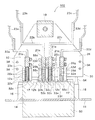
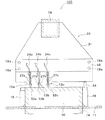
ここで、図1は、性能試験を行なう電気計器を背面側から見た斜視図であり、図2は、移動体が係合位置にある場合における、本実施の形態による電気計器用自動結線装置を示す正面図である。図3は、本実施の形態による電気計器用自動結線装置を示す側面図であり、図4は、本実施の形態による電気計器用自動結線装置を示す水平断面図(図2のIV−IV線断面図)である。図5は、本実施の形態による電気計器用自動結線装置を示す水平断面図(図2のV−V線断面図)であり、図6は、移動体が待機位置にある場合における、本実施の形態による電気計器用自動結線装置を示す正面図である。また図7(a)(b)は、スプリング体および電流測定端子を示す拡大正面図であり、図8は、スプリング体の変形例を示す断面図(スプリングホルダの長手方向に沿った断面図)である。
Hereinafter, an embodiment of the present invention will be described with reference to FIGS.
Here, FIG. 1 is a perspective view of an electrical instrument for performing a performance test as seen from the back side, and FIG. 2 is an automatic connection device for an electrical instrument according to the present embodiment when the moving body is in the engaged position. FIG. FIG. 3 is a side view showing the automatic wiring device for electric instruments according to the present embodiment, and FIG. 4 is a horizontal sectional view showing the automatic wiring device for electric meters according to the present embodiment (IV-IV line in FIG. 2). FIG. FIG. 5 is a horizontal cross-sectional view (cross-sectional view taken along the line V-V in FIG. 2) illustrating the automatic wiring device for electric meters according to the present embodiment, and FIG. 6 illustrates the present embodiment when the moving body is in the standby position. It is a front view which shows the automatic connection apparatus for electric meters by the form of this. FIGS. 7A and 7B are enlarged front views showing the spring body and the current measuring terminal, and FIG. 8 is a cross-sectional view showing a modification of the spring body (cross-sectional view along the longitudinal direction of the spring holder). It is.
まず、図1により、本実施の形態による電気計器用自動結線装置を用いて性能試験を行なう電気計器の概略について説明する。 First, with reference to FIG. 1, an outline of an electric meter that performs a performance test using the automatic wiring device for an electric meter according to the present embodiment will be described.
図1に示す電気計器50は、例えば、電力を積算して計量する電力量計からなっている。この電気計器50は、略直方体形状のボックス51と、ボックス51の一面(背面)51aから外方へ突出する4本の電流端子52a〜52dと、ボックス51の背面51aから外方へ突出する3本の電圧端子53a〜53cとを有している。
The
このうち4本の電流端子52a〜52dは、それぞれ、1S端子52a、3S端子52b、3L端子52c、および1L端子52dから構成されており、横方向に並んで配置されている。また3本の電圧端子53a〜53cは、それぞれ、P1端子53a、P2端子53b、およびP3端子53cから構成されており、電流端子52a〜52dより上方の位置において横方向に並んで配置されている。また、ボックス51の一側面51bには、接地端子54が設けられている。
Of these, the four
次に、図2乃至図6により、本実施の形態による電気計器用自動結線装置の概略について説明する。
図2乃至図6に示す電気計器用自動結線装置100は、上述した電気計器50が装着され、当該電気計器50を図示しない試験装置に接続することにより、電気計器50の性能試験を行なうものである。このような電気計器用自動結線装置100は、固定された装置本体10と、装置本体10に対して上下方向に移動自在に設けられた移動体30とを備えている。
Next, referring to FIGS. 2 to 6, an outline of the automatic wiring device for electric meters according to the present embodiment will be described.
The
このうち装置本体10は、性能試験を行なう際に電気計器50が挿入される開口14を有するとともに鉛直方向に延びる前面板11と、この前面板11の内側で前面板11に対して垂直に連結されるとともに水平方向に延びる固定板15とを有している。また前面板11の内側であって開口14の下方に、電気計器50を案内するガイド部材16が設けられ、さらに、ガイド部材16の内側端部に、電気計器50を係止して位置決めするストッパ17が設けられている。なお、ガイド部材16およびストッパ17は、それぞれ合成樹脂等の非導電性材料からなっている。
Among them, the apparatus
また、固定板15の下面に、合成樹脂等の非導電性材料からなる端子用ブロック18が取り付けられている。さらに、固定板15の下面であって、端子用ブロック18の後方(すなわち前面板11の反対方向)の位置に、エアシリンダ等からなる昇降手段19が取り付けられている。
A
ところで、装置本体10は、各々が一対の端子板26a〜26dからなり、電気計器50の電流端子52a〜52dにそれぞれ接続される電流測定端子12a〜12dと、各々が一対の端子板27a〜27cからなり、電気計器50の電圧端子53a〜53cに接続される電圧測定端子13a〜13cとを有している。各電流測定端子12a〜12dおよび各電圧測定端子13a〜13cは、それぞれ前面板11の開口14内部で電気計器50の挿入方向を向いて配置されている。
By the way, the apparatus
電流測定端子12a〜12dは、電気計器50の1S端子52aに接続される1S用測定端子12a、3S端子52bに接続される3S用測定端子12b、3L端子52cに接続される3L用測定端子12c、および1L端子52dに接続される1L用測定端子12dからなっている。これら電流測定端子12a〜12dは、それぞれ対応する金属製の接点ベース21a〜21dに連結され、各接点ベース21a〜21dは、上述した端子用ブロック18の下面に連結されている。さらに接点ベース21a〜21dに、それぞれ折り曲げられた銅板からなる電流用接続部材22a〜22dが接続され、電流用接続部材22a〜22dに、それぞれ電流用接続導線23a〜23dが接続されている(図4参照)。そして各電流測定端子12a〜12dは、対応する接点ベース21a〜21d、電流用接続部材22a〜22d、および電流用接続導線23a〜23dを順次介して、図示しない試験装置に電気的に接続されている。
The
他方、電圧測定端子13a〜13cは、電気計器50のP1端子53aに接続されるP1用測定端子13a、P2端子53bに接続されるP2用測定端子13b、およびP3端子53cに接続されるP3用測定端子13cからなっている。これら電圧測定端子13a〜13cは、それぞれ上述した端子用ブロック18の前面に取り付けられている。また、電圧測定端子13a〜13cに、それぞれ電圧用接続導線24a〜24cが接続されている(図5参照)。そして電圧測定端子13a〜13cは、電圧用接続導線24a〜24cを介して、図示しない試験装置に電気的に接続されている。
On the other hand, the voltage measurement terminals 13a to 13c are the P1 measurement terminal 13a connected to the P1 terminal 53a of the
ところで、移動体30は、上述した昇降手段19に連結されるとともに水平方向に延びる昇降板31と、昇降板31上に取り付けられたスプリングホルダ33a〜33gと、各スプリングホルダ33a〜33gに保持され、各電流測定端子12a〜12dの一対の端子板26a〜26d外方にそれぞれ嵌め込まれる一対のスプリング体32a〜32dとを有している。なお、図2、図4、および図6に示すように、一対のスプリング体32a〜32dのうち、一対のスプリング体32aは、スプリングホルダ33a、33bにそれぞれ保持され、一対のスプリング体32bは、スプリングホルダ33c、33dにそれぞれ保持され、一対のスプリング体32cは、スプリングホルダ33d、33eにそれぞれ保持され、かつ、一対のスプリング体32dは、スプリングホルダ33f、33gにそれぞれ保持されている。
By the way, the moving
また昇降板31上面には、鉛直方向に延びる複数のガイドバー34が取り付けられている。ガイドバー34は、昇降板31と一体となって昇降し、この際、端子用ブロック18を貫通して形成された貫通孔18a内を摺動するようになっている。
A plurality of guide bars 34 extending in the vertical direction are attached to the upper surface of the elevating
移動体30は、昇降手段19の伸縮動作により一体となって昇降し、装置本体10に対して係合位置(図2参照)と待機位置(図6参照)とをとるようになっている。
The moving
すなわち昇降手段19を縮退させた場合、移動体30が上昇し、移動体30が係合位置に移動する(図2)。この係合位置において、移動体30の一対のスプリング体32a〜32dは、対応する電流測定端子12a〜12dの一対の端子板26a〜26d外方に嵌め込まれ、この一対の端子板26a〜26dを電気計器50の電流端子52a〜52dに対して押圧する。これに対して、昇降手段19を伸長させた場合、移動体30が下降し、移動体30が待機位置に移動する(図6)。この待機位置において、移動体30の一対のスプリング体32a〜32dは、対応する電流測定端子12a〜12dの一対の端子板26a〜26dから外れる。
That is, when the elevating
次に、図7(a)(b)により、スプリング体および電流測定端子の構成について詳細に説明する。なお図7(a)は、待機位置におけるスプリング体および電流測定端子の関係を示す拡大正面図であり、図7(b)は、係合位置におけるスプリング体および電流測定端子の関係を示す拡大正面図である。以下、1S端子52aに対応するスプリング体32aおよび電流測定端子12aについて代表して説明するが、他のスプリング体32b〜32dおよび電流測定端子12b〜12dについてもその構成は同様である。
Next, the configuration of the spring body and the current measurement terminal will be described in detail with reference to FIGS. 7A is an enlarged front view showing the relationship between the spring body and the current measurement terminal in the standby position, and FIG. 7B is an enlarged front view showing the relationship between the spring body and the current measurement terminal in the engagement position. FIG. Hereinafter, the
図7(a)(b)に示すように、スプリング体32aは、湾曲したステンレス鋼等の板バネからなるとともに、その両端がそれぞれスプリングホルダ33a、33bの取付溝35内に取り付けられている。なおスプリングホルダ33a、33bは、合成樹脂などの非導電性材料からなっている。
As shown in FIGS. 7 (a) and 7 (b), the
また電流測定端子12aの各端子板26aは、それぞれ、係合位置(図7(b))において電気計器50の電流端子52aに当接する内側金属板28aと、内側金属板28aの外方に設けられ、係合位置において対応するスプリング体32aに当接して係合する外側金属板28bとからなっている。すなわち、図7(b)に示す係合位置において、一対のスプリング体32aは、対応する電流測定端子12aの一対の端子板26aの外側金属板28b外方に嵌め込まれ、各外側金属板28bを介して各内側金属板28aを電流端子52aに対して押圧する。他方、図7(a)に示す待機位置において、一対の端子板26aの内側金属板28a同士の間隔は、係合位置における内側金属板28a同士の間隔より広がり、これにより電流端子52aと一対の端子板26aとは、互いにわずかに離間する。
Each
なお各端子板26aのうち、内側金属板28aは、高い導電性を有する金属、例えば銅からなっている。他方、外側金属板28bは、内側金属板28aと異なる材質からなり、例えば弾性を有するステンレス鋼等の金属からなっている。このように、電流測定端子12aの各端子板26aが内側金属板28aと外側金属板28bとからなっていることにより、スプリング体32aが上下に移動する場合に、スプリング体32aと内側金属板28aとが直接摺接することがない。したがって、スプリング体32aによって内側金属板28aが摩耗することを防止することができる。
Of each
なお、スプリング体は、図8に示すように、一端がスプリングホルダ33a〜33gに埋設されたスプリングプランジャ36からなっていても良い。図8において、各スプリングプランジャ36は、先細の先端を有する筒体37と、筒体37の内部空間37aに沿って移動可能に設けられ、一部が筒体37の内部空間37aから露出するボール38と、筒体37内に設けられ、ボール38を筒体37先端側へ押圧するバネ39とを有している。そして各スプリングプランジャ36は、スプリングホルダ33a〜33gに形成された取付孔33s内に取り付けられ、この際ボール38の一部が電流測定端子12a〜12dの一対の端子板26a〜26d側に突出するようになっている。なお図8に示すように、各スプリングホルダ33a〜33gは、それぞれ複数(図8では3つ)のスプリングプランジャ36を保持していることが好ましい。
In addition, as shown in FIG. 8, a spring body may consist of the
あるいは、スプリング体は、スプリングホルダ33a〜33gに取り付けられた多面接触子からなっていても良い。
Alternatively, the spring body may be composed of multi-face contactors attached to the
次に、このような構成からなる本実施の形態の作用について述べる。
まず、予め図示しないスイッチを待機位置側に切り換えることにより、昇降手段19を伸長させ、移動体30を下降させて待機位置に移動しておく(図6)。次に、前面板11の開口14内に性能試験を行なう電気計器50を挿入し、ストッパ17に当接するまで電気計器50をガイド部材16に沿って奥側に押し込む。
Next, the operation of the present embodiment having such a configuration will be described.
First, by switching a switch (not shown) to the standby position side in advance, the elevating
この際、電気計器50の各電流端子52a〜52dは、それぞれ対応する電流測定端子12a〜12dの一対の端子板26a〜26d間に配置される。この場合、電流端子52a〜52dと一対の端子板26a〜26dとは、それぞれ互いにわずかに離間しているので、電流端子52a〜52dと各一対の端子板26a〜26dとの間は、まだ電気的に接続されていない。これに対して、電気計器50の各電圧端子53a〜53cは、それぞれ対応する電圧測定端子13a〜13cの一対の端子板27a〜27c間にしっかりと挿入され、各電圧端子53a〜53cと各一対の端子板27a〜27cとが互いに電気的に接続される。
At this time, each of the
次に、図示しないスイッチを係合位置側に切り換えることにより、昇降手段19を縮退させ、移動体30を上昇させて係合位置に移動する(図2)。これにより、移動体30のスプリングホルダ33a〜33gおよび一対のスプリング体32a〜32dが、装置本体10に対して上昇する。この際、一対のスプリング体32a〜32dは、対応する電流測定端子12a〜12dの一対の端子板26a〜26dに摺接しながら上昇する。その後、一対のスプリング体32a〜32dは、各一対の端子板26a〜26d外方にしっかりと嵌め込まれ、かつ一対の端子板26a〜26dを電流端子52a〜52dに対して挟んだ状態で押圧する。これにより、一対の端子板26a〜26dと対応する電流端子52a〜52dとが確実に接続される。
Next, by switching a switch (not shown) to the engagement position side, the elevating
このようにして、電気計器用自動結線装置100を介して電気計器50と図示しない試験装置の電源側とが結線された後、試験装置から電流測定端子12a〜12dおよび電圧測定端子13a〜13cを介して電気計器50に電流を流すことにより、電気計器50の性能試験を行なう。
Thus, after the
電気計器50の性能試験が終了した後、図示しないスイッチを待機位置側に切り換える。これにより、昇降手段19を伸長させ、移動体30が下降する。次に、前面板11の開口14内から電気計器50を抜き取る。その後、性能試験を行なう他の電気計器50を、上述した方法と同様にして前面板11の開口14内に挿入し(電気計器50を掛け替える)、性能試験を行なう。
After the performance test of the
このように、本実施の形態によれば、ボックス51と、ボックス51の背面51aから外方へ突出する電流端子52a〜52dおよび電圧端子53a〜53cとを有する電気計器50の性能試験を行なう際、複数の電気計器50を順番に容易に掛け替えることができ、効率よく性能試験を実施することができる。
Thus, according to the present embodiment, when performing a performance test of the
また、本実施の形態によれば、移動体30は、装置本体10に対して係合位置と待機位置とをとり、移動体30の一対のスプリング体32a〜32dは、係合位置において、対応する電流測定端子12a〜12dの一対の端子板26a〜26d外方に嵌め込まれて一対の端子板26a〜26dを電気計器50の電流端子52a〜52dに押圧する。また、移動体30の一対のスプリング体32a〜32dは、待機位置において、対応する電流測定端子12a〜12dの一対の端子板26a〜26dから外れる。
Further, according to the present embodiment, the moving
このことにより、電気計器50を掛け替える際には、移動体30を待機位置とし、一対の端子板26a〜26d同士を広げることにより、電気計器50の各電流端子52a〜52dを一対の端子板26a〜26d間に容易に挿入し、また各電流端子52a〜52dを一対の端子板26a〜26d間から容易に取り外すことができる。したがって、電気計器50の掛け替え作業が容易となる。これに対して、電気計器50の性能試験を行なう際には、移動体30を係合位置とし、各一対の端子板26a〜26dを電気計器50の各電流端子52a〜52dに対して押圧する。このようにして、各一対の端子板26a〜26dと各電流端子52a〜52dとを確実に接続することができる。
Thus, when the
さらに、本実施の形態によれば、一対の端子板26a〜26dにより電気計器50の各電流端子52a〜52dを両側から挟み込む構造であるため、性能試験中に電気計器50に対して負荷が加わることがない。また、前面板11の開口14内に電気計器50を挿入した際、電気計器用自動結線装置100の部品が前面板11から前方にはみ出すことがないので、性能試験の作業を行ないやすい。
Furthermore, according to the present embodiment, since the
なお、電気計器50は、図1に示すような三相3線式の電力量計の他、単相2線式、単相3線式、または三相4線式の電力量計であっても良い。すなわち電気計器50は、2本、4本、または6本の電流端子を有するとともに、2本、3本、または4本の電圧端子を有していてもよい。これに対応して、装置本体10は、各電流端子に接続される2本、4本、または6本の電流測定端子と、各電圧端子に接続される2本、3本、または4本の電圧測定端子とを有していても良い。
The
ところで、一般に、電気計器50の電圧測定端子13a〜13cを流れる電流は、電気計器50の電流測定端子12a〜12dを流れる電流と比べて小さい。このため、上述したように各電圧測定端子13a〜13cの一対の端子板27a〜27c間に各電圧端子53a〜53cを差し込むだけで、各電圧測定端子13a〜13cと各電圧端子53a〜53cとを十分に電気的に接続することができる。しかしながら、これに限らず、電圧測定端子13a〜13cの構成を電流測定端子12a〜12dの構成と同様にしても良い。すなわち、移動体30に電圧測定端子13a〜13c用の一対のスプリング体を設け、この一対のスプリング体は、係合位置において、対応する電圧測定端子13a〜13cの一対の端子板27a〜27c外方に嵌め込まれて一対の端子板27a〜27cを電気計器の電圧端子53a〜53cに押圧し、また待機位置において、対応する電圧測定端子13a〜13cの一対の端子板27a〜27cから外れるようになっていても良い。
By the way, generally, the current flowing through the voltage measurement terminals 13a to 13c of the
10 装置本体
11 前面板
12a〜12d 電流測定端子
13a〜13c 電圧測定端子
14 開口
15 固定板
16 ガイド部材
17 ストッパ
18 端子用ブロック
19 昇降手段(エアシリンダ)
21a〜21d 接点ベース
22a〜22d 電流用接続部材
23a〜23d 電流用接続導線
24a〜24c 電圧用接続導線
26a〜26d 一対の端子板
27a〜27c 一対の端子板
28a 内側金属板
28b 外側金属板
30 移動体
31 昇降板
32a〜32d スプリング体
33a〜33g スプリングホルダ
34 ガイドバー
50 電気計器
51 ボックス
52a〜52d 電流端子
53a〜53c 電圧端子
100 電気計器用自動結線装置
DESCRIPTION OF
21a to
Claims (7)
各々が一対の端子板からなり、電流端子に接続される電流測定端子と、各々が一対の端子板からなり、電圧端子に接続される電圧測定端子とを有する装置本体と、
装置本体に対して移動自在に設けられ、各電流測定端子の一対の端子板外方に嵌め込まれる一対のスプリング体を有する移動体とを備え、
移動体は、装置本体に対して係合位置と待機位置とをとり、移動体の一対のスプリング体は、係合位置において、対応する電流測定端子の一対の端子板外方に嵌め込まれて一対の端子板を電気計器の電流端子に押圧し、移動体の一対のスプリング体は、待機位置において、対応する電流測定端子の一対の端子板から外れることを特徴とする電気計器用自動結線装置。 In an automatic wiring device for an electric meter, which is equipped with an electric meter having a box and a current terminal and a voltage terminal protruding outward from one side of the box, and performing a performance test by connecting the electric meter to the test device,
An apparatus body having a current measuring terminal connected to the current terminal, each consisting of a pair of terminal plates, and a voltage measuring terminal connected to the voltage terminal, each consisting of a pair of terminal plates;
A movable body provided movably with respect to the apparatus main body, and having a pair of spring bodies fitted into the outside of the pair of terminal plates of each current measurement terminal;
The movable body takes an engagement position and a standby position with respect to the apparatus main body, and the pair of spring bodies of the movable body are fitted to the outside of the pair of terminal plates of the corresponding current measurement terminals at the engagement position. An automatic connection device for an electric meter, wherein the terminal plate of the electric instrument is pressed against the current terminal of the electric meter, and the pair of spring bodies of the moving body is detached from the pair of terminal plates of the corresponding current measuring terminal at the standby position.
装置本体の各電流測定端子および各電圧測定端子は、前面板の開口内部で電気計器の挿入方向を向いて配置されていることを特徴とする請求項1記載の電気計器用自動結線装置。 The device body has a front plate having an opening into which an electric meter is inserted when performing a performance test,
2. The automatic connection device for an electric meter according to claim 1, wherein each of the current measurement terminals and each voltage measurement terminal of the device main body is arranged inside the opening of the front plate so as to face the insertion direction of the electric meter.
昇降手段は、移動体を上昇させることにより移動体を係合位置に移動し、移動体を下降させることにより移動体を待機位置に移動することを特徴とする請求項1または2記載の電気計器用自動結線装置。 The apparatus main body has a fixed plate connected perpendicularly to the front plate, and an elevating means fixed to the fixed plate and moving the moving body up and down.
3. The electric meter according to claim 1, wherein the elevating means moves the moving body to the engaging position by raising the moving body, and moves the moving body to the standby position by lowering the moving body. Automatic connection device.
スプリング体は、両端がスプリングホルダに取り付けられた湾曲した板バネからなることを特徴とする請求項1乃至3のいずれか一項記載の電気計器用自動結線装置。 The moving body has a spring holder that holds the spring body,
4. The automatic connection device for an electric meter according to claim 1, wherein the spring body is formed of a curved leaf spring having both ends attached to a spring holder.
スプリング体は、一端がスプリングホルダに埋設されたスプリングプランジャからなることを特徴とする請求項1乃至3のいずれか一項記載の電気計器用自動結線装置。 The moving body has a spring holder that holds the spring body,
4. The automatic connection device for an electric meter according to claim 1, wherein the spring body is composed of a spring plunger having one end embedded in a spring holder.
Priority Applications (1)
| Application Number | Priority Date | Filing Date | Title |
|---|---|---|---|
| JP2008203038A JP4767999B2 (en) | 2008-08-06 | 2008-08-06 | Automatic wiring device for electrical meters |
Applications Claiming Priority (1)
| Application Number | Priority Date | Filing Date | Title |
|---|---|---|---|
| JP2008203038A JP4767999B2 (en) | 2008-08-06 | 2008-08-06 | Automatic wiring device for electrical meters |
Publications (2)
| Publication Number | Publication Date |
|---|---|
| JP2010038767A true JP2010038767A (en) | 2010-02-18 |
| JP4767999B2 JP4767999B2 (en) | 2011-09-07 |
Family
ID=42011472
Family Applications (1)
| Application Number | Title | Priority Date | Filing Date |
|---|---|---|---|
| JP2008203038A Active JP4767999B2 (en) | 2008-08-06 | 2008-08-06 | Automatic wiring device for electrical meters |
Country Status (1)
| Country | Link |
|---|---|
| JP (1) | JP4767999B2 (en) |
Cited By (18)
| Publication number | Priority date | Publication date | Assignee | Title |
|---|---|---|---|---|
| JP2012083319A (en) * | 2010-10-14 | 2012-04-26 | Densoku Techno Co Ltd | Automatic connection apparatus |
| CN102608562A (en) * | 2012-04-11 | 2012-07-25 | 江西省电力科学研究院 | Integrated detection production line of electric energy meter, terminal and concentrator |
| CN102680836A (en) * | 2012-05-31 | 2012-09-19 | 广东电网公司佛山供电局 | Intelligent terminal testing device with automatic metering function |
| CN102879661A (en) * | 2011-07-15 | 2013-01-16 | 华北电力科学研究院有限责任公司 | Method and system for detecting distribution network automatic terminal |
| CN102955146A (en) * | 2012-11-20 | 2013-03-06 | 辽宁省电力有限公司电力科学研究院 | Device for measuring metering accuracy of intelligent meter in salt spray test box |
| CN103341454A (en) * | 2013-06-28 | 2013-10-09 | 杭州厚达自动化系统有限公司 | Automatically sorting method for electric energy meter |
| CN103698560A (en) * | 2013-12-31 | 2014-04-02 | 深圳市思达仪表有限公司 | High-frequency electromagnetic field anti-interference testing tool |
| CN103698736A (en) * | 2013-11-27 | 2014-04-02 | 国家电网公司 | Automatic combined wiring instrument |
| JP2014202531A (en) * | 2013-04-02 | 2014-10-27 | デンソクテクノ株式会社 | Automatic wire connection device |
| CN104237840A (en) * | 2014-09-25 | 2014-12-24 | 国家电网公司 | Integrated junction device for single-phase kilowatt-hour meter inspection and electric strength test |
| JP2015011022A (en) * | 2013-07-02 | 2015-01-19 | デンソクテクノ株式会社 | Automatic wiring apparatus |
| JP2015155809A (en) * | 2014-02-20 | 2015-08-27 | 四国計測工業株式会社 | Watthour meter automatic wire connection device |
| WO2018072055A1 (en) * | 2016-10-18 | 2018-04-26 | 深圳市思达仪表有限公司 | High frequency electromagnetic field anti-interference testing tool |
| CN107976648A (en) * | 2017-10-15 | 2018-05-01 | 四川罡正电子科技有限公司 | A kind of Electric control measuring instrument automatic connection test method |
| CN110068787A (en) * | 2018-01-24 | 2019-07-30 | 郑州三晖电气股份有限公司 | A kind of electric energy meter meter adapting-seat high current docking mechanism |
| JP2019132665A (en) * | 2018-01-30 | 2019-08-08 | 日本電気計器検定所 | Wire connecting device for electrical instruments |
| CN112881770A (en) * | 2021-03-03 | 2021-06-01 | 王悦 | Electric energy meter capable of automatically maintaining stable contact of electric wire and use method thereof |
| WO2023066369A1 (en) * | 2021-10-22 | 2023-04-27 | 浙江万胜智能科技股份有限公司 | Module power-on test device for electricity meter based on internet of things |
Families Citing this family (1)
| Publication number | Priority date | Publication date | Assignee | Title |
|---|---|---|---|---|
| CN102778666A (en) * | 2012-06-11 | 2012-11-14 | 湖北省电力公司武汉供电公司电能计量中心 | Wire connector for rapid verification of intelligent electric meter |
Citations (3)
| Publication number | Priority date | Publication date | Assignee | Title |
|---|---|---|---|---|
| JPS60145578U (en) * | 1984-03-06 | 1985-09-27 | 富士通株式会社 | connector |
| JPS62187860U (en) * | 1986-05-22 | 1987-11-30 | ||
| JP2006058129A (en) * | 2004-08-19 | 2006-03-02 | Enegate:Kk | Connector for watt-hour meter |
-
2008
- 2008-08-06 JP JP2008203038A patent/JP4767999B2/en active Active
Patent Citations (3)
| Publication number | Priority date | Publication date | Assignee | Title |
|---|---|---|---|---|
| JPS60145578U (en) * | 1984-03-06 | 1985-09-27 | 富士通株式会社 | connector |
| JPS62187860U (en) * | 1986-05-22 | 1987-11-30 | ||
| JP2006058129A (en) * | 2004-08-19 | 2006-03-02 | Enegate:Kk | Connector for watt-hour meter |
Cited By (19)
| Publication number | Priority date | Publication date | Assignee | Title |
|---|---|---|---|---|
| JP2012083319A (en) * | 2010-10-14 | 2012-04-26 | Densoku Techno Co Ltd | Automatic connection apparatus |
| CN102879661A (en) * | 2011-07-15 | 2013-01-16 | 华北电力科学研究院有限责任公司 | Method and system for detecting distribution network automatic terminal |
| CN102608562A (en) * | 2012-04-11 | 2012-07-25 | 江西省电力科学研究院 | Integrated detection production line of electric energy meter, terminal and concentrator |
| CN102680836A (en) * | 2012-05-31 | 2012-09-19 | 广东电网公司佛山供电局 | Intelligent terminal testing device with automatic metering function |
| CN102955146A (en) * | 2012-11-20 | 2013-03-06 | 辽宁省电力有限公司电力科学研究院 | Device for measuring metering accuracy of intelligent meter in salt spray test box |
| JP2014202531A (en) * | 2013-04-02 | 2014-10-27 | デンソクテクノ株式会社 | Automatic wire connection device |
| CN103341454A (en) * | 2013-06-28 | 2013-10-09 | 杭州厚达自动化系统有限公司 | Automatically sorting method for electric energy meter |
| JP2015011022A (en) * | 2013-07-02 | 2015-01-19 | デンソクテクノ株式会社 | Automatic wiring apparatus |
| CN103698736A (en) * | 2013-11-27 | 2014-04-02 | 国家电网公司 | Automatic combined wiring instrument |
| CN103698560A (en) * | 2013-12-31 | 2014-04-02 | 深圳市思达仪表有限公司 | High-frequency electromagnetic field anti-interference testing tool |
| JP2015155809A (en) * | 2014-02-20 | 2015-08-27 | 四国計測工業株式会社 | Watthour meter automatic wire connection device |
| CN104237840A (en) * | 2014-09-25 | 2014-12-24 | 国家电网公司 | Integrated junction device for single-phase kilowatt-hour meter inspection and electric strength test |
| WO2018072055A1 (en) * | 2016-10-18 | 2018-04-26 | 深圳市思达仪表有限公司 | High frequency electromagnetic field anti-interference testing tool |
| CN107976648A (en) * | 2017-10-15 | 2018-05-01 | 四川罡正电子科技有限公司 | A kind of Electric control measuring instrument automatic connection test method |
| CN110068787A (en) * | 2018-01-24 | 2019-07-30 | 郑州三晖电气股份有限公司 | A kind of electric energy meter meter adapting-seat high current docking mechanism |
| JP2019132665A (en) * | 2018-01-30 | 2019-08-08 | 日本電気計器検定所 | Wire connecting device for electrical instruments |
| CN112881770A (en) * | 2021-03-03 | 2021-06-01 | 王悦 | Electric energy meter capable of automatically maintaining stable contact of electric wire and use method thereof |
| CN112881770B (en) * | 2021-03-03 | 2022-10-14 | 江苏盛德电子仪表有限公司 | Electric energy meter capable of automatically maintaining stable contact of electric wire and use method thereof |
| WO2023066369A1 (en) * | 2021-10-22 | 2023-04-27 | 浙江万胜智能科技股份有限公司 | Module power-on test device for electricity meter based on internet of things |
Also Published As
| Publication number | Publication date |
|---|---|
| JP4767999B2 (en) | 2011-09-07 |
Similar Documents
| Publication | Publication Date | Title |
|---|---|---|
| JP4767999B2 (en) | Automatic wiring device for electrical meters | |
| JP4750196B2 (en) | Automatic wiring device for electrical meters | |
| TWI328684B (en) | Differential measurement probe having retractable double cushioned variable spacing probing tips and providing eos/esd protection | |
| CN107024634B (en) | One kind using power-on detection device for harness test | |
| CN103703381A (en) | Probe card for power device | |
| CN204129082U (en) | Connector test socket and connector testing device | |
| CN105527465A (en) | Connector testing socket and connector testing device | |
| CN104617424B (en) | Connector for Flat Cable | |
| JPH10214667A (en) | Ic socket | |
| KR101637035B1 (en) | A Conductive Contactor | |
| JP5209072B2 (en) | Automatic wiring device for electrical meters | |
| CN204560009U (en) | Printed circuit board measuring point draws keyset | |
| KR200454242Y1 (en) | MV Electronic Meter Adapter | |
| JP2013183581A (en) | Distribution board | |
| US20070279078A1 (en) | Kelvin contact measurement device and kelvin contact measurement method | |
| US10847921B2 (en) | Test plug for a FT switch | |
| JP4849229B2 (en) | Surface mount connector | |
| JP2724675B2 (en) | IC measuring jig | |
| KR20180117152A (en) | Measurement of insulation current in insulation body | |
| JP5415394B2 (en) | Test plug and electrical test method using the test plug | |
| KR102572320B1 (en) | Adapter for test apparatus | |
| CN219496582U (en) | Test fixture | |
| CN102914670A (en) | Insulation resistance test clamp | |
| KR100900452B1 (en) | Electric circuit open-short tester | |
| WO2018150478A1 (en) | Substrate inspection probe and substrate inspection device, and substrate inspection method using same |
Legal Events
| Date | Code | Title | Description |
|---|---|---|---|
| A977 | Report on retrieval |
Free format text: JAPANESE INTERMEDIATE CODE: A971007 Effective date: 20101210 |
|
| A131 | Notification of reasons for refusal |
Free format text: JAPANESE INTERMEDIATE CODE: A131 Effective date: 20101217 |
|
| A521 | Request for written amendment filed |
Free format text: JAPANESE INTERMEDIATE CODE: A523 Effective date: 20110208 |
|
| A131 | Notification of reasons for refusal |
Free format text: JAPANESE INTERMEDIATE CODE: A131 Effective date: 20110301 |
|
| A521 | Request for written amendment filed |
Free format text: JAPANESE INTERMEDIATE CODE: A523 Effective date: 20110420 |
|
| TRDD | Decision of grant or rejection written | ||
| A01 | Written decision to grant a patent or to grant a registration (utility model) |
Free format text: JAPANESE INTERMEDIATE CODE: A01 Effective date: 20110517 |
|
| A61 | First payment of annual fees (during grant procedure) |
Free format text: JAPANESE INTERMEDIATE CODE: A61 Effective date: 20110615 |
|
| R150 | Certificate of patent or registration of utility model |
Ref document number: 4767999 Country of ref document: JP Free format text: JAPANESE INTERMEDIATE CODE: R150 Free format text: JAPANESE INTERMEDIATE CODE: R150 |
|
| FPAY | Renewal fee payment (event date is renewal date of database) |
Free format text: PAYMENT UNTIL: 20140624 Year of fee payment: 3 |
|
| R250 | Receipt of annual fees |
Free format text: JAPANESE INTERMEDIATE CODE: R250 |
|
| R250 | Receipt of annual fees |
Free format text: JAPANESE INTERMEDIATE CODE: R250 |
|
| R250 | Receipt of annual fees |
Free format text: JAPANESE INTERMEDIATE CODE: R250 |
|
| R250 | Receipt of annual fees |
Free format text: JAPANESE INTERMEDIATE CODE: R250 |
|
| R250 | Receipt of annual fees |
Free format text: JAPANESE INTERMEDIATE CODE: R250 |
|
| R250 | Receipt of annual fees |
Free format text: JAPANESE INTERMEDIATE CODE: R250 |
|
| R250 | Receipt of annual fees |
Free format text: JAPANESE INTERMEDIATE CODE: R250 |
|
| R250 | Receipt of annual fees |
Free format text: JAPANESE INTERMEDIATE CODE: R250 |
|
| R250 | Receipt of annual fees |
Free format text: JAPANESE INTERMEDIATE CODE: R250 |
|
| R250 | Receipt of annual fees |
Free format text: JAPANESE INTERMEDIATE CODE: R250 |