JP2010038552A - Multiwavelength interferometric displacement measuring method and apparatus - Google Patents
Multiwavelength interferometric displacement measuring method and apparatus Download PDFInfo
- Publication number
- JP2010038552A JP2010038552A JP2008198185A JP2008198185A JP2010038552A JP 2010038552 A JP2010038552 A JP 2010038552A JP 2008198185 A JP2008198185 A JP 2008198185A JP 2008198185 A JP2008198185 A JP 2008198185A JP 2010038552 A JP2010038552 A JP 2010038552A
- Authority
- JP
- Japan
- Prior art keywords
- wavelength
- wavelengths
- interference
- optical comb
- laser
- Prior art date
- Legal status (The legal status is an assumption and is not a legal conclusion. Google has not performed a legal analysis and makes no representation as to the accuracy of the status listed.)
- Granted
Links
- 238000006073 displacement reaction Methods 0.000 title claims abstract description 40
- 238000000034 method Methods 0.000 title claims description 18
- 238000005259 measurement Methods 0.000 claims abstract description 87
- 230000003287 optical effect Effects 0.000 claims abstract description 59
- 230000010355 oscillation Effects 0.000 claims abstract description 12
- 230000035559 beat frequency Effects 0.000 claims description 11
- 238000000691 measurement method Methods 0.000 claims description 4
- 238000006243 chemical reaction Methods 0.000 claims 1
- 238000010586 diagram Methods 0.000 description 6
- 238000013461 design Methods 0.000 description 5
- 238000001228 spectrum Methods 0.000 description 3
- 230000015572 biosynthetic process Effects 0.000 description 1
- 229910052792 caesium Inorganic materials 0.000 description 1
- TVFDJXOCXUVLDH-UHFFFAOYSA-N caesium atom Chemical compound [Cs] TVFDJXOCXUVLDH-UHFFFAOYSA-N 0.000 description 1
- 239000002131 composite material Substances 0.000 description 1
- 230000000694 effects Effects 0.000 description 1
- 239000000835 fiber Substances 0.000 description 1
- 238000005305 interferometry Methods 0.000 description 1
- 238000012545 processing Methods 0.000 description 1
- 239000004065 semiconductor Substances 0.000 description 1
- 238000003786 synthesis reaction Methods 0.000 description 1
- 238000012360 testing method Methods 0.000 description 1
Images


Classifications
-
- G—PHYSICS
- G01—MEASURING; TESTING
- G01B—MEASURING LENGTH, THICKNESS OR SIMILAR LINEAR DIMENSIONS; MEASURING ANGLES; MEASURING AREAS; MEASURING IRREGULARITIES OF SURFACES OR CONTOURS
- G01B9/00—Measuring instruments characterised by the use of optical techniques
- G01B9/02—Interferometers
- G01B9/02001—Interferometers characterised by controlling or generating intrinsic radiation properties
- G01B9/02007—Two or more frequencies or sources used for interferometric measurement
- G01B9/02008—Two or more frequencies or sources used for interferometric measurement by using a frequency comb
-
- G—PHYSICS
- G01—MEASURING; TESTING
- G01B—MEASURING LENGTH, THICKNESS OR SIMILAR LINEAR DIMENSIONS; MEASURING ANGLES; MEASURING AREAS; MEASURING IRREGULARITIES OF SURFACES OR CONTOURS
- G01B9/00—Measuring instruments characterised by the use of optical techniques
- G01B9/02—Interferometers
- G01B9/02001—Interferometers characterised by controlling or generating intrinsic radiation properties
- G01B9/02002—Interferometers characterised by controlling or generating intrinsic radiation properties using two or more frequencies
- G01B9/02005—Interferometers characterised by controlling or generating intrinsic radiation properties using two or more frequencies using discrete frequency stepping or switching
-
- G—PHYSICS
- G01—MEASURING; TESTING
- G01B—MEASURING LENGTH, THICKNESS OR SIMILAR LINEAR DIMENSIONS; MEASURING ANGLES; MEASURING AREAS; MEASURING IRREGULARITIES OF SURFACES OR CONTOURS
- G01B9/00—Measuring instruments characterised by the use of optical techniques
- G01B9/02—Interferometers
- G01B9/02055—Reduction or prevention of errors; Testing; Calibration
- G01B9/02062—Active error reduction, i.e. varying with time
- G01B9/02067—Active error reduction, i.e. varying with time by electronic control systems, i.e. using feedback acting on optics or light
- G01B9/02069—Synchronization of light source or manipulator and detector
-
- G—PHYSICS
- G01—MEASURING; TESTING
- G01B—MEASURING LENGTH, THICKNESS OR SIMILAR LINEAR DIMENSIONS; MEASURING ANGLES; MEASURING AREAS; MEASURING IRREGULARITIES OF SURFACES OR CONTOURS
- G01B2290/00—Aspects of interferometers not specifically covered by any group under G01B9/02
- G01B2290/60—Reference interferometer, i.e. additional interferometer not interacting with object
Landscapes
- Physics & Mathematics (AREA)
- General Physics & Mathematics (AREA)
- Engineering & Computer Science (AREA)
- Automation & Control Theory (AREA)
- Optics & Photonics (AREA)
- Length Measuring Devices By Optical Means (AREA)
- Instruments For Measurement Of Length By Optical Means (AREA)
Abstract
Description
本発明は、多波長干渉変位測定方法及び装置に係り、特に、複数の波長のレーザ光により、各波長で測定される干渉測定値を得て、各波長の組み合わせからレーザ光の波長よりも等価的に長い合成波長で測定レンジを拡大して、干渉計本体から対象物までの距離または変位を干渉測定する多波長干渉変位測定方法及び装置の改良に関する。 The present invention relates to a multi-wavelength interference displacement measurement method and apparatus, and in particular, obtains an interference measurement value measured at each wavelength with a plurality of wavelengths of laser light, and is equivalent to the wavelength of the laser light from a combination of the wavelengths. In particular, the present invention relates to an improved multi-wavelength interference displacement measuring method and apparatus for interferometrically measuring the distance or displacement from an interferometer body to an object by expanding the measurement range with a long synthetic wavelength.
対象物(ターゲットとも称する)までの距離または対象物の変位を高精度に測定する方法の一つに、光波干渉を利用した距離の測定がある。 One of the methods for measuring the distance to an object (also referred to as a target) or the displacement of the object with high accuracy is a distance measurement using light wave interference.
この光波干渉を利用した距離(変位)の測定は、数百nmの波長をものさしとした高精度な距離(変位)の測定方法である(特許文献1参照)。 This distance (displacement) measurement using light wave interference is a highly accurate distance (displacement) measurement method with a wavelength of several hundreds of nanometers (see Patent Document 1).
しかしながら、光波干渉計をセンサとして対象物の変位や形状を測定する場合に、波長λの半分の長さ以上の急激な変位や、段差の形状は測定できないと言う欠点がある。 However, when measuring the displacement and shape of an object using a light wave interferometer as a sensor, there is a drawback that it is impossible to measure an abrupt displacement greater than half the wavelength λ or a step shape.
これに対して、複数波長での測定結果を組み合わせた、合成波長により測定レンジを拡大する方法が、非特許文献1などで示されている。この方法は、次式(1)に示す如く、波長λ1で得られる位相φ1と波長λ2によって得られる位相φ2の差φsをとると、次式(2)で示す合成波長λsで干渉測定したものと等価な結果が得られることを利用している。
On the other hand, Non-Patent
φs=φ2−φ1 …(1)
λs=λ2λ1/|λ2−λ1| …(2)
φ s = φ 2 −φ 1 (1)
λ s = λ 2 λ 1 / | λ 2 −λ 1 | (2)
2波長の合成波長によって測定レンジを拡大する場合には、式(2)で示した、差の波長(周波数)を正確に作り出すことが重要である。特に、2波長の差を小さくして波長を大きく拡大して合成するときほど、正確さが求められる。差の波長Δλの誤差δΔλに対する合成波長の誤差δλsは、近似的に次式(3)で示される。 In the case where the measurement range is expanded by two synthetic wavelengths, it is important to accurately create the difference wavelength (frequency) shown by the equation (2). In particular, the accuracy is required as the difference between the two wavelengths is reduced and the wavelength is greatly expanded. The error δλ s of the combined wavelength with respect to the error δΔλ of the difference wavelength Δλ is approximately expressed by the following equation (3).
λs=λ2λ1/|λ2−λ1|〜λ1 2/Δλ …(2)’
δλs〜(λ1 2/Δλ2)*δΔλ …(3)
λ s = λ 2 λ 1 / | λ 2 −λ 1 | ˜λ 1 2 / Δλ (2) ′
δλ s ˜ (λ 1 2 / Δλ 2 ) * δΔλ (3)
例えば、λ=1μm、Δλ=0.001μmとして、1mmの合成波長λsを生成する場合、誤差がλに対して6桁に相当する0.000001μmのわずかな誤差が発生した場合、合成波長λsの誤差δλsは、1μmにもなる。
For example, when λ = 1 μm and Δλ = 0.001 μm to generate a
つまり、合成波長方式によって測定レンジを拡大しようとする時は、所望の波長差で発生する波長の安定度が極めて高い2台のレーザを使用するか、あるいは、極めて高い精度で波長走査が可能な、高価なレーザが必要であった。 In other words, when trying to expand the measurement range by the synthetic wavelength method, two lasers with extremely high stability of the wavelength generated by the desired wavelength difference can be used, or wavelength scanning can be performed with extremely high accuracy. An expensive laser was required.
しかしながら、周波数が正確に値付けされたレーザはあまり多くなく、現状で手軽に入手できるものとなると更に限られてしまう。従って、測定原理上、より好ましいと判断されるレーザの波長に対して、入手できるレーザが限られてしまっていることが、合成波長を効果的に、あるいは手軽に、実現することを阻害してしまっている。 However, there are not many lasers whose frequencies are accurately priced, and the number of lasers that can be easily obtained at present is further limited. Therefore, the fact that the available lasers are limited with respect to the wavelength of the laser that is judged to be more preferable from the measurement principle, impedes the realization of the synthetic wavelength effectively or easily. I'm stuck.
本発明は、前記従来の問題点を解消するべくなされたもので、安定度の高い高価なレーザや高精度に波長を可変できるレーザを使用しないで、安価な広いレンジの干渉変位測定を実現することを課題とする。 The present invention has been made to solve the above-mentioned conventional problems, and realizes an inexpensive and wide range interference displacement measurement without using an expensive laser with high stability or a laser capable of changing the wavelength with high accuracy. This is the issue.
本発明は、複数の波長のレーザ光により、各波長で測定される干渉測定値(参照光と測定光による干渉の位相)を得て、各波長の組み合わせからレーザ光の波長よりも等価的に長い合成波長で測定レンジを拡大して、干渉計本体から対象物までの距離または変位を干渉測定する際に、前記複数のレーザ光の波長を、光コムを用いて測定するようにして、前記課題を解決したものである。 The present invention obtains an interference measurement value (phase of interference between reference light and measurement light) measured at each wavelength by using laser light of a plurality of wavelengths, and is equivalent to the wavelength of the laser light from the combination of the wavelengths. When interferometrically measuring the distance or displacement from the interferometer body to the object by expanding the measurement range with a long synthetic wavelength, the wavelengths of the plurality of laser beams are measured using an optical comb, It solves the problem.
ここで、前記光コムを用いて波長可変レーザの発振波長を測定してフィードバック制御をかけることにより、所定の複数の波長のレーザ光を得ることができる。 Here, laser light having a plurality of predetermined wavelengths can be obtained by measuring the oscillation wavelength of the wavelength tunable laser using the optical comb and performing feedback control.
また、波長可変レーザを任意の波長で発振させて、複数の波長での干渉測定値を得て、各干渉測定値を得た際のレーザ光の波長(周波数)を光コムで測定して、干渉計本体から対象物までの距離を算出することができる。 In addition, by oscillating the wavelength tunable laser at an arbitrary wavelength, obtaining interference measurement values at a plurality of wavelengths, measuring the wavelength (frequency) of the laser beam when obtaining each interference measurement value with an optical comb, The distance from the interferometer body to the object can be calculated.
また、複数のレーザを用いて、各レーザから発振されるレーザ光の波長を光コムで測定しながら干渉測定を行い、干渉計本体から対象物までの距離を算出することができる。 Further, using a plurality of lasers, interference measurement can be performed while measuring the wavelength of laser light emitted from each laser with an optical comb, and the distance from the interferometer body to the object can be calculated.
また、前記光コムを含む一つの周波数測定系で、前記複数の波長を測定することができる。 The plurality of wavelengths can be measured with one frequency measurement system including the optical comb.
また、複数の波長で干渉測定値を得る際、一つの波長を基準として相対的に波長差を正確に与える制御を行って干渉測定を行うか、あるいは、各波長での測定値を得た時の波長差を、一つの波長を基準として相対的な差として測定することができる。 Also, when obtaining interference measurement values at multiple wavelengths, perform interference measurement by controlling the relative wavelength accurately with reference to one wavelength, or obtain measurement values at each wavelength. Can be measured as a relative difference with respect to one wavelength.
また、一方の波長と光コムによって発生するビート周波数と、他方の波長と光コムによって発生するビート周波数に対して、光コムの次数分を加味して周波数差を算出し、この周波数差を波長差に換算することができる。 In addition, the frequency difference is calculated by taking into account the order of the optical comb with respect to the beat frequency generated by one wavelength and the optical comb, and the beat frequency generated by the other wavelength and the optical comb. It can be converted into a difference.
また、3つ以上の波長から2つずつの組み合わせの合成波長での位相差を算出し、その分解能の違いを利用して距離を決定することができる。 Further, it is possible to calculate a phase difference at a combined wavelength of two combinations from three or more wavelengths, and determine the distance using the difference in resolution.
本発明は、また、複数の波長のレーザ光により、各波長で測定される干渉測定値を得て、各波長の組み合わせからレーザ光の波長よりも等価的に長い合成波長で測定レンジを拡大して、干渉計本体から対象物までの距離または変位を干渉測定する多波長干渉変位測定装置において、前記複数のレーザ光の波長を測定するために光コムを備えたことを特徴とする多波長干渉変位測定装置を提供するものである。 The present invention also obtains an interference measurement value measured at each wavelength by using laser beams of a plurality of wavelengths, and expands the measurement range from a combination of each wavelength to a synthetic wavelength that is equivalently longer than the wavelength of the laser beam. A multi-wavelength interference displacement measuring apparatus for interferometrically measuring the distance or displacement from the interferometer body to the object, comprising a multi-wavelength interference comprising an optical comb for measuring the wavelengths of the plurality of laser beams A displacement measuring device is provided.
ここで、前記光コムを用いて波長可変レーザの発振波長を測定してフィードバック制御を行う手段を備えることにより、所定の複数の波長を得ることができる。 Here, by providing means for performing feedback control by measuring the oscillation wavelength of the wavelength tunable laser using the optical comb, a plurality of predetermined wavelengths can be obtained.
また、波長可変レーザを任意の波長で発振させて、複数の波長での干渉測定値を得る手段と、各干渉測定値を得た際のレーザ光の波長(周波数)を光コムで測定して、干渉計本体から対象物までの距離の算出に用いる手段とを備えることにより、干渉計本体から対象物までの距離を算出することができる。 In addition, the wavelength variable laser is oscillated at an arbitrary wavelength to obtain interference measurement values at a plurality of wavelengths, and the wavelength (frequency) of the laser beam when each interference measurement value is obtained is measured with an optical comb. By using the means for calculating the distance from the interferometer body to the object, the distance from the interferometer body to the object can be calculated.
また、複数のレーザと、各レーザから発振されるレーザ光の波長を光コムで測定しながら干渉測定を行い、干渉計本体から対象物までの距離の算出に用いる手段とを備えることができる。 In addition, a plurality of lasers and means for performing interference measurement while measuring the wavelength of laser light oscillated from each laser with an optical comb and calculating the distance from the interferometer body to the object can be provided.
また、前記複数の波長を測定するための、前記光コムを含む一つの周波数測定系を備えることができる。 Moreover, one frequency measurement system including the optical comb for measuring the plurality of wavelengths can be provided.
また、複数の波長で干渉測定値を得る際、一つの波長を基準として相対的に波長差を正確に与える制御を行って干渉測定を行う手段か、あるいは、各波長での測定値を得た時の波長差を、一つの波長を基準として相対的な差として測定する手段を備えることができる。 In addition, when obtaining interference measurement values at a plurality of wavelengths, it is a means for performing interference measurement by controlling to give a wavelength difference relatively accurately with reference to one wavelength, or obtained measurement values at each wavelength. Means may be provided for measuring the time difference as a relative difference with respect to one wavelength.
また、一方の波長と光コムによって発生するビート周波数と、他方の波長と光コムによって発生するビート周波数に対して、光コムの次数分を加味して周波数差を算出し、この周波数差を波長差に換算する手段を備えることができる。 In addition, the frequency difference is calculated by taking into account the order of the optical comb with respect to the beat frequency generated by one wavelength and the optical comb, and the beat frequency generated by the other wavelength and the optical comb. Means for converting to a difference can be provided.
また、3つ以上の波長から2つずつの組み合わせの合成波長での位相差を算出する手段と、その分解能の違いを利用して距離を決定する手段と、を備えることができる。 Further, it is possible to provide means for calculating a phase difference at a combined wavelength of two combinations of three or more wavelengths, and means for determining a distance using the difference in resolution.
本発明によれば、安定度の高い高価なレーザや、高精度に波長を可変できる高価なレーザを使用せずに、安価なレーザで多波長干渉変位測定を実現できるため、装置の低価格化をはかることができる。 According to the present invention, it is possible to realize multi-wavelength interference displacement measurement with an inexpensive laser without using an expensive laser with high stability and an expensive laser capable of changing the wavelength with high accuracy, thereby reducing the cost of the apparatus. Can be measured.
以下、図面を参照して、本発明の実施形態を詳細に説明する。 Hereinafter, embodiments of the present invention will be described in detail with reference to the drawings.
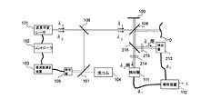
本発明の第1実施形態にかかる変位測定装置の構成を図2に示す。 FIG. 2 shows the configuration of the displacement measuring apparatus according to the first embodiment of the present invention.
本実施形態では、波長(周波数)可変レーザ101の出力光をビームスプリッタ106で分割する。一方の光をビームスプリッタ108で分割し、一方は、例えば平面鏡でなる参照鏡109で反射させて参照光とする。他方は、距離(変位)の測定対象である対象物110を照射し、そこからの反射光である測定光と、前記参照光をビームスプリッタ108で重ね合せる。参照光と測定光の信号を検出器111によって受光し、干渉強度信号により、干渉計本体から対象物110までの距離(対象物110の変位)を測定する。
In this embodiment, the output light of the wavelength (frequency)
又、ビームスプリッタ106からの反射光を、ビームスプリッタ107を介して光コム104と重ね合わせて、検出器105で受光する。光コム104と波長可変レーザ101のビート信号を周波数測定装置103で周波数解析して、コントローラ102により、レーザ101の発振波長(周波数)をフィードバック制御する。
The reflected light from the
本実施形態においては、波長可変レーザ101を所定の波長λ1で発振させて、得られた干渉信号から位相φ1を算出する。波長λ1は、波長可変レーザ101の周波数を光コム104とのビート周波数によって正確に測定して、所定の波長λ1になるように波長可変レーザ101を制御することによって得られる。図3に波長を可変した時のビート信号の周波数変化の様子を模式的に示す。
In the present embodiment, the
次に、光コム104とのビート信号によって波長(周波数)を測定しながら、合成波長λsを実現するために必要な、波長λ1とは異なる所定の波長λ2で波長可変レーザ101を発振させる。そして、参照光と測定光の反射光による干渉信号を取得し、位相φ2の解析値を得る。ここで、得られた2つの位相φ1とφ2の差φs(=φ1−φ2)から、合成波長λsを使った長さに換算して、次式(4)に示す如く、λs/2の範囲内で参照光と測定光の光路長差の形で対象物110までの距離(変位)Lを得ることが出来る。
Next, the wavelength
L=(φs/2π)*(λs/2) …(4) L = (φ s / 2π) * (λ s / 2) (4)
光コム104は、セシウムの原子時計を基準にして光の周波数を15桁以上の精度で測定できる装置である。従って、所定の波長λ1とλ2は、最大で15桁の精度で制御可能である。よって、波長λ1とλ2を元に合成した波長λSは、十分に高い精度で実現できる。
The
第1実施形態の測定手順をまとめると、次のようになる。
(1)レーザ101の波長を設計波長λ1に制御する。
(2)干渉測定し、位相φ1を得る。
(3)レーザ101の波長を設計波長λ2に制御する。
(4)干渉測定し、位相φ2を得る。
(5)予め設計した位相φ1とφ2の差φSを式(4)に代入し、距離Lを算出する。
The measurement procedure of the first embodiment is summarized as follows.
(1) The wavelength of the
(2) Interferometric measurement is performed to obtain the phase φ 1 .
(3) The wavelength of the
(4) Measure interference to obtain the phase φ 2 .
(5) The difference φ S between the phases φ 1 and φ 2 designed in advance is substituted into the equation (4), and the distance L is calculated.
図2では、一つのレーザ101を所定の波長λ1とλ2に可変し、それぞれ順次測定する方法を示しているが、図4に示す第2実施形態のように、2波長以上を同時に出力するレーザ201を使って、波長λ1とλ2による干渉信号を分割して同時に取る光学系(ビームスプリッタ210、バンドパスフィルタ214、215)を設けても良い。この場合、検出器105や周波数測定装置103からなる波長可変レーザ201の周波数(波長)測定系を波長λ1とλ2用にそれぞれ別々に用意しても構わないし、図4に示したように、一つの周波数測定系で、両方の周波数(波長)λ1、λ2を測定して制御することも可能である。
FIG. 2 shows a method in which one
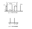
図5は、レーザの発振スペクトルと、その時に得られる干渉ビート信号の例を模式的に示している。図5(a1)に示す如く、波長λ1とλ2と光コム104の干渉のビート信号を、光コム104の周波数間隔frepの1/2までの範囲で観察した場合には、図5(b1)に示す如く、それぞれの差の組み合わせの数の周波数のビート信号Δf1、Δf2、Δf12が観測される。一方、図5(a2)に示す如く、波長λ1とλ2が、光コム104の異なる周波数(次数)との間で干渉している場合には、図5(b2)に示す如く、波長λ1とλ2は、それぞれの近隣の光との差の周波数のビート信号Δf1、Δf2が検出される。このような状況で、図5(a3)に示す如く、いずれかの波長(図ではλ2)を変化させると、変化させた分だけビート信号の周波数の変化が生じる。この現象を活用すれば、1つの周波数測定系で、波長λ1とλ2を区別することが可能である。
FIG. 5 schematically shows an example of a laser oscillation spectrum and an interference beat signal obtained at that time. As shown in FIG. 5 (a 1 ), when the beat signal of the interference between the wavelengths λ 1 and λ 2 and the
又、本発明を利用すれば、図6に示す第3実施形態のような構成での干渉測定への応用も可能である。 If the present invention is used, it can be applied to interference measurement with the configuration as in the third embodiment shown in FIG.
本実施形態では、波長可変レーザ101を任意の波長λ1’で発振させて、位相φ1を測定する。次に、λ1’とは異なる波長λ2’で発振させて、位相φ2を測定する。位相φ1とφ2を測定した際の正確な波長を、検出器105や周波数測定装置103などからなる周波数測定系で測定し、その結果を式(2)に代入して合成波長λsを算出し、位相φ1とφ2から得られる合成位相φsと共に式(4)に代入することで、対象物110までの距離Lを算出することができる。
In the present embodiment, the
このとき、波長λ1’とλ2’の値によって合成波長λsの値は変わるが、実測値によって得た合成波長λsで長さに変換するだけであるため、測定結果には何ら影響を及ぼさない。 At this time, the value of the synthetic wavelength λ s changes depending on the values of the wavelengths λ 1 ′ and λ 2 ′, but only the length is converted into the length at the synthetic wavelength λ s obtained by the actual measurement value. Does not affect.
本実施形態では、レーザ101の波長を制御するための特別な装置も不要で、例えば半導体レーザのように電流可変で簡単に波長を変えられるようなレーザが使用できるために、測定装置を極めて簡素化することが出来る。
In this embodiment, there is no need for a special device for controlling the wavelength of the
本実施形態の測定手順をまとめると次のようになる。
(1)レーザ101を任意の波長λ1’で発振させる。
(2)干渉測定し、位相φ1を得ると同時に、そのときの正確な発振波長λ1を測定する。
(3)レーザ101を別の波長λ2’に可変し発振させる。
(4)干渉測定し、位相φ2を得ると同時に、そのときの正確な発振波長λ2を測定する。
(5)式(1)(2)(5)に代入して、対象物110までの距離Lを算出する。
The measurement procedure of this embodiment is summarized as follows.
(1) The
(2) Interferometric measurement is performed to obtain the phase φ 1 and at the same time the exact oscillation wavelength λ 1 is measured.
(3) The
(4) Interferometric measurement is performed to obtain the phase φ 2 and at the same time the exact oscillation wavelength λ 2 is measured.
(5) The distance L to the
又、本発明の手法を応用すれば、図7に示す第4実施形態の如く、発振波長の安定度が低く安価なレーザを使っても、合成波長により広いレンジの干渉測定が実現できる。 Further, by applying the method of the present invention, a wide range of interference measurements can be realized depending on the combined wavelength even when using an inexpensive laser having low oscillation wavelength stability as in the fourth embodiment shown in FIG.
本実施形態では、波長λ1を発振するレーザ416と波長λ2を発振するレーザ417を同軸に重ね合わせ、参照鏡109と対象物110からなる干渉光学系に入射する。波長λ1とλ2によって干渉測定を行ない、それぞれの位相φ1とφ2を得て、その差φsを算出する。その際の波長λsの正確な値は、検出器105や周波数測定装置103からなる周波数測定系によって得られたλ1とλ2を使用して正確に算出する。そして得られた合成位相φsと合成波長λsから、対象物110までの距離Lを得ることができる。位相φ1とφ2のそれぞれを測定した瞬間の波長λ1とλ2が得られる本実施形態においては、たとえ、レーザ416、417の周波数が不安定であったとしても、距離(変位)Lの測定には大きな影響は及ぼさない。
In the present embodiment, a
2波長の合成波長によって測定レンジを拡大する干渉測定では、測定分解能は合成波長λsと合成位相φsの分割数によって決まる。例えば、λs=10mmとし、φ2とφ1の差で得られるφsの分割数が500だとすると、このときの測定分解能は10μm程度になってしまう。これに対して、測定に使用する波長の数を増やして組み合わせによって出来る合成波長の種類を増やすことで、広いレンジを確保しつつかつ高い分解能の測定を簡単に実現できる。図8に示す第5実施形態のように、波長可変レーザ101の波長をλ1、λ2、λ3に切り替えて、それぞれの波長で参照光と測定光の位相差φ1、φ2、φ3を得る。そして、各波長の組み合わせによって作り出される、合成波長λsi,jでの位相差φi,jから対象物110の位置や変位を広い範囲でかつ高い分解能で測定できる。
In interferometric measurement in which the measurement range is expanded by two synthetic wavelengths, the measurement resolution is determined by the number of divisions of the synthetic wavelength λ s and the synthetic phase φ s . For example, assuming that λ s = 10 mm and the number of divisions of φ s obtained by the difference between φ 2 and φ 1 is 500, the measurement resolution at this time is about 10 μm. On the other hand, by increasing the number of wavelengths used for measurement and increasing the number of synthetic wavelengths that can be combined, measurement with high resolution can be easily realized while ensuring a wide range. As in the fifth embodiment shown in FIG. 8, the wavelength of the wavelength
本実施形態の測定手順をまとめると、次の通りである。
(1)レーザ101の波長を設計波長λ1に制御する。
(2)干渉測定し、位相φ1を得る。
(3)レーザ101の波長を設計波長λ2に制御する。
(4)干渉測定し、位相φ2を得る。
(5)レーザ101の波長を設計波長λ3に制御する。
(6)干渉測定し、位相φ3を得る。
(7)位相φ1とφ2とφ3の差の組み合わせで位相差φi,jを算出し、対象物110までの距離Lを算出する。
The measurement procedure of this embodiment is summarized as follows.
(1) The wavelength of the
(2) Interferometric measurement is performed to obtain the phase φ 1 .
(3) The wavelength of the
(4) Measure interference to obtain the phase φ 2 .
(5) The wavelength of the
(6) Interferometric measurement is performed to obtain the phase φ 3 .
(7) The phase difference φ i, j is calculated from the combination of the differences between the phases φ 1 , φ 2, and φ 3 , and the distance L to the
例えば、λ1=1μm、λ2=0.9999μm、λ3=0.98μmとする。この場合、λ1とλ2の組み合わせの合成波長λs21は9999μm、λ3とλ1の組み合わせによる合成波長λs31は49μmとなる。それぞれの合成波長のもと導き出される、φs21、φs31の分割数を、先に述べた例と同じ500分割だとすると、λs21では約10μm分解能の測定が、λs31では50nm分解能の測定ができることになる。更にλ1、λ2、λ3いずれかの短波長での測定結果も併用すれば、10mmのレンジを1nm分解能で測定することも可能となる。 For example, λ 1 = 1 μm, λ 2 = 0.9999 μm, and λ 3 = 0.98 μm. In this case, the combined wavelength λ s21 of the combination of λ 1 and λ 2 is 9999 μm, and the combined wavelength λ s31 of the combination of λ 3 and λ 1 is 49 μm. Assuming that the number of divisions of φ s21 and φ s31 derived under the respective synthetic wavelengths is 500, which is the same as the example described above, about 10 μm resolution can be measured at λs 21 and 50 nm resolution can be measured at λ s31. become. Furthermore, if a measurement result at a short wavelength of any one of λ 1 , λ 2 , and λ 3 is also used, it is possible to measure a 10 mm range with 1 nm resolution.
本発明で実現する場合には、例えば、図1や図4では、可変させる波長を3つにすることで容易に実現できる。図4の場合には3波長を発振するレーザを使用する。図6では、3種類のレーザを使用することにより容易に実施することが出来る。4波長以上の場合、同様に簡単に実現できることは明らかである。 In the case of realizing the present invention, for example, in FIGS. 1 and 4, it can be easily realized by changing the wavelength to be changed to three. In the case of FIG. 4, a laser that oscillates three wavelengths is used. In FIG. 6, it can be easily implemented by using three types of lasers. Obviously, it can be easily realized in the case of four or more wavelengths.
それぞれの実施形態の中で、光の周波数を測定する装置として示した光コム104は、コムのスペクトル間隔内の限られた周波数領域ごとを高い分解能できることが基本となっている。そのため、光コム104のどの周波数の光との干渉によって生じたビート信号なのか、別途、次数Nを決定する必要がある。レーザの発振周波数の予備値やレーザ周波数の可変時の分解能などによって、次数Nを決定できない場合には、図9に示す第6実施形態のように、波長計601などの波長を測定できる手段と併用して、次数Nを決定し、波長可変レーザ101の波長λ1、λ2の測定や、発振周波数の制御に使用しても良い。
In each of the embodiments, the
λ1とλ2といった多波長での測定値を得る際に、λ1の波長を基準として、相対的に波長差Δλをつけたλ2を使って測定を行い、λ1とλ2の合成波長によって対象物への距離Lを測定しても良い。 in obtaining the measurements at multiple wavelengths such as lambda 1 and lambda 2, as a reference wavelength of lambda 1, it was measured with a lambda 2 wearing a relatively wavelength difference [Delta] [lambda], lambda 1 and lambda 2 Synthesis The distance L to the object may be measured by the wavelength.
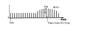
通常、光周波数を測定する場合には、『産総研TODAY Vol. 8 No.1 モード同期ファイバレーザを用いた広帯域光コムhttp://www.aist.go.jp/aist_j/aistinfo/aist_today/vol08_01/p29.html』に示されているように、fCEOを正確に値付けされた、光コムが必要である。そのためには、fCEOを決めれるだけの十分に周波数帯域の広い光コムが必要である。 In general, when measuring optical frequency, the AIST TODAY Vol. 8 No.1 mode-locked fiber laser using broadband optical com http://www.aist.go.jp/aist_j/aistinfo/aist_today/vol08_01 As shown in /p29.html, we need an optical comb that accurately priced f CEO . To that end, an optical comb with a sufficiently wide frequency band that can determine f CEO is required.
一方で、合成波長による測定の場合には、式(3)により、λ1とλ2の相対的な波長差Δλの正確さが測定精度に大きく影響するため、絶対値があいまいな光コムを使って、Δλを値付けして合成波長λsを決めても、実用的に十分高い精度で測定可能である。Δλの決定には、λ1と光コムによって発生するビート周波数Δf1とλ2と光コムによって発生するビート周波数Δf2を次数N分を加味して周波数差Δf12を算出し、Δf12からΔλを換算すればよい。これにより、提案する光波干渉計に使用する周波数測定に使用する光コムは、測定に使用する波長域をカバーする最低限のものであれば良いために、より低価格に実現することが可能となる。 On the other hand, in the case of measurement using a synthetic wavelength, the accuracy of the relative wavelength difference Δλ between λ 1 and λ 2 greatly affects the measurement accuracy according to Equation (3). Even if it is used and Δλ is priced to determine the combined wavelength λs, it can be measured with sufficiently high accuracy in practical use. The determination of [Delta] [lambda], in consideration of lambda 1 and the order N times the beat frequency Delta] f 2 generated by the beat frequency Delta] f 1 and lambda 2 and the optical comb generated by an optical comb calculates the frequency difference Delta] f 12, from Delta] f 12 Δλ may be converted. As a result, the optical comb used for the frequency measurement used in the proposed lightwave interferometer may be a minimum one that covers the wavelength range used for the measurement, and can be realized at a lower price. Become.
なお、前記実施形態においては、参照鏡109として平面鏡が用いられていたが、代りに、光軸が合わせ易く、調整が容易なレトロリフレクタを用いても良い。又、対象物110の表面にレトロリフレクタを取付けても良い。
In the above-described embodiment, a plane mirror is used as the
101、201…波長可変レーザ
102…コントローラ
103…周波数測定装置
104…光コム
105、111、213…検出器
106、107、108、210…ビームスプリッタ
109…参照鏡
110…対象物
112…解析装置
214、215…バンドパスフィルタ
416、417…レーザ
601…波長計
DESCRIPTION OF
Claims (16)
前記複数のレーザ光の波長を、光コムを用いて測定することを特徴とする多波長干渉変位測定方法。 Interferometer measurement values measured at each wavelength are obtained with laser beams of multiple wavelengths, and the measurement range is expanded from the combination of each wavelength to a synthetic wavelength that is equivalently longer than the wavelength of the laser beam. When interferometrically measuring the distance or displacement to an object,
A multi-wavelength interference displacement measuring method, wherein wavelengths of the plurality of laser beams are measured using an optical comb.
前記複数のレーザ光の波長を測定するために光コムを備えたことを特徴とする多波長干渉変位測定装置。 Interferometer measurement values measured at each wavelength are obtained with laser beams of multiple wavelengths, and the measurement range is expanded from the combination of each wavelength to a synthetic wavelength that is equivalently longer than the wavelength of the laser beam. In a multi-wavelength interference displacement measuring device that interferometrically measures the distance or displacement to an object,
A multi-wavelength interference displacement measuring apparatus comprising an optical comb for measuring wavelengths of the plurality of laser beams.
Priority Applications (2)
| Application Number | Priority Date | Filing Date | Title |
|---|---|---|---|
| JP2008198185A JP5511162B2 (en) | 2008-07-31 | 2008-07-31 | Multi-wavelength interference displacement measuring method and apparatus |
| EP20090166890 EP2149778B1 (en) | 2008-07-31 | 2009-07-30 | Multiwavelength interferometric displacement measuring method and apparatus |
Applications Claiming Priority (1)
| Application Number | Priority Date | Filing Date | Title |
|---|---|---|---|
| JP2008198185A JP5511162B2 (en) | 2008-07-31 | 2008-07-31 | Multi-wavelength interference displacement measuring method and apparatus |
Publications (2)
| Publication Number | Publication Date |
|---|---|
| JP2010038552A true JP2010038552A (en) | 2010-02-18 |
| JP5511162B2 JP5511162B2 (en) | 2014-06-04 |
Family
ID=41259920
Family Applications (1)
| Application Number | Title | Priority Date | Filing Date |
|---|---|---|---|
| JP2008198185A Expired - Fee Related JP5511162B2 (en) | 2008-07-31 | 2008-07-31 | Multi-wavelength interference displacement measuring method and apparatus |
Country Status (2)
| Country | Link |
|---|---|
| EP (1) | EP2149778B1 (en) |
| JP (1) | JP5511162B2 (en) |
Cited By (5)
| Publication number | Priority date | Publication date | Assignee | Title |
|---|---|---|---|---|
| WO2011118255A1 (en) * | 2010-03-26 | 2011-09-29 | 株式会社日立製作所 | Distance measuring device and method of measuring distance |
| JP2012004426A (en) * | 2010-06-18 | 2012-01-05 | Mitsutoyo Corp | Unmodulated stabilization laser device |
| JP2012088274A (en) * | 2010-10-22 | 2012-05-10 | Mitsutoyo Corp | Displacement measuring device |
| JP2014190759A (en) * | 2013-03-26 | 2014-10-06 | Mitsutoyo Corp | Frequency measuring apparatus and frequency measurement method |
| JP2015528924A (en) * | 2012-07-19 | 2015-10-01 | カール・ツァイス・エスエムティー・ゲーエムベーハー | Projection exposure apparatus for microlithography with optical distance measurement system |
Families Citing this family (1)
| Publication number | Priority date | Publication date | Assignee | Title |
|---|---|---|---|---|
| JP5736247B2 (en) * | 2011-06-23 | 2015-06-17 | 株式会社日立製作所 | Distance measuring method and apparatus |
Citations (7)
| Publication number | Priority date | Publication date | Assignee | Title |
|---|---|---|---|---|
| JPH04299203A (en) * | 1991-03-28 | 1992-10-22 | Yokogawa Electric Corp | Absolute length measurer |
| JP2553276B2 (en) * | 1991-03-27 | 1996-11-13 | エイチイー・ホールディングス・インコーポレーテッド・ディービーエー・ヒューズ・エレクトロニクス | Three-wavelength optical measuring device and method |
| JP2004340690A (en) * | 2003-05-14 | 2004-12-02 | National Institute Of Advanced Industrial & Technology | Light frequency measuring instrument and measuring method using multi-color mode-locked laser |
| JP2007040994A (en) * | 2005-08-01 | 2007-02-15 | Mitsutoyo Corp | Interference measuring system |
| JP2007333428A (en) * | 2006-06-12 | 2007-12-27 | Ricoh Co Ltd | Shape measuring device, and shape measuring method |
| JP2008051674A (en) * | 2006-08-25 | 2008-03-06 | National Institute Of Advanced Industrial & Technology | Positioning mechanism |
| JP2009198477A (en) * | 2008-02-19 | 2009-09-03 | Korea Advanced Inst Of Science & Technol | Method and system for measuring absolute distance using optical frequency generator |
Family Cites Families (1)
| Publication number | Priority date | Publication date | Assignee | Title |
|---|---|---|---|---|
| JP3423229B2 (en) | 1998-11-17 | 2003-07-07 | 株式会社ミツトヨ | Light wave interferometer and length measuring method using light wave interferometer |
-
2008
- 2008-07-31 JP JP2008198185A patent/JP5511162B2/en not_active Expired - Fee Related
-
2009
- 2009-07-30 EP EP20090166890 patent/EP2149778B1/en active Active
Patent Citations (7)
| Publication number | Priority date | Publication date | Assignee | Title |
|---|---|---|---|---|
| JP2553276B2 (en) * | 1991-03-27 | 1996-11-13 | エイチイー・ホールディングス・インコーポレーテッド・ディービーエー・ヒューズ・エレクトロニクス | Three-wavelength optical measuring device and method |
| JPH04299203A (en) * | 1991-03-28 | 1992-10-22 | Yokogawa Electric Corp | Absolute length measurer |
| JP2004340690A (en) * | 2003-05-14 | 2004-12-02 | National Institute Of Advanced Industrial & Technology | Light frequency measuring instrument and measuring method using multi-color mode-locked laser |
| JP2007040994A (en) * | 2005-08-01 | 2007-02-15 | Mitsutoyo Corp | Interference measuring system |
| JP2007333428A (en) * | 2006-06-12 | 2007-12-27 | Ricoh Co Ltd | Shape measuring device, and shape measuring method |
| JP2008051674A (en) * | 2006-08-25 | 2008-03-06 | National Institute Of Advanced Industrial & Technology | Positioning mechanism |
| JP2009198477A (en) * | 2008-02-19 | 2009-09-03 | Korea Advanced Inst Of Science & Technol | Method and system for measuring absolute distance using optical frequency generator |
Non-Patent Citations (5)
| Title |
|---|
| JPN6013011360; Jonghan Jin, Young-Jin Kim, Yunseok Kim and Seung-Woo Kim: '"Absolute length calibration of gauge blocks using optical comb of a femtosecond pulse laser"' OPTICS EXPRESS Vol.14, No.13, 20060626, pages 5968-5974 * |
| JPN6013011362; Nicolas Schuler, Yves Salvade, Samuel Leveque, Rene Dandliker, Ronald Holzwarth: '"Frequency-comb-referenced two-wavelength source for absolute distance measurement"' OPTICS LETTERS Vol.31, No.21, 200611, pages 3101-3103 * |
| JPN6013011366; Mikko Merimma, K. Nyholm, M. Vainio, Antti Lassila: '"Traceability of Laser Frequency Calibrations at MIKES"' IEEE TRANSACTIONS ON INSTRUMENTATION AND MEASUREMENT Vol.56, No.2, 200704, pages 500-504 * |
| JPN6013011371; Youichi Bitou, Thomas R. Schibli, Kaoru Minoshima: '"Accurate wide-range displacement measurement using tunable diode laser and optical frequency comb g' OPTICS EXPRESS Vol.14, No.2, 200601, pages 644-654 * |
| JPN6013011374; Yves Salvade, Nicolas Schuler, Samuel Leveque, Sebastien Le Floch: '"High-accuracy absolute distance measurement using frequency comb referenced multiwavelength source"' APPLIED OPTICS Vol.47, No.14, 20080510, pages 2715-2720 * |
Cited By (8)
| Publication number | Priority date | Publication date | Assignee | Title |
|---|---|---|---|---|
| WO2011118255A1 (en) * | 2010-03-26 | 2011-09-29 | 株式会社日立製作所 | Distance measuring device and method of measuring distance |
| JP2011203188A (en) * | 2010-03-26 | 2011-10-13 | Hitachi Ltd | Distance measuring device and method of measuring distance |
| US8982332B2 (en) | 2010-03-26 | 2015-03-17 | Hitachi, Ltd. | Distance measuring device and distance measuring method |
| JP2012004426A (en) * | 2010-06-18 | 2012-01-05 | Mitsutoyo Corp | Unmodulated stabilization laser device |
| JP2012088274A (en) * | 2010-10-22 | 2012-05-10 | Mitsutoyo Corp | Displacement measuring device |
| JP2015528924A (en) * | 2012-07-19 | 2015-10-01 | カール・ツァイス・エスエムティー・ゲーエムベーハー | Projection exposure apparatus for microlithography with optical distance measurement system |
| US9759550B2 (en) | 2012-07-19 | 2017-09-12 | Carl Zeiss Smt Gmbh | Projection exposure apparatus for microlithography comprising an optical distance measurement system |
| JP2014190759A (en) * | 2013-03-26 | 2014-10-06 | Mitsutoyo Corp | Frequency measuring apparatus and frequency measurement method |
Also Published As
| Publication number | Publication date |
|---|---|
| EP2149778A1 (en) | 2010-02-03 |
| JP5511162B2 (en) | 2014-06-04 |
| EP2149778B1 (en) | 2013-06-19 |
Similar Documents
| Publication | Publication Date | Title |
|---|---|---|
| JP5511163B2 (en) | Distance measuring method and apparatus by light wave interference | |
| JP2553276B2 (en) | Three-wavelength optical measuring device and method | |
| JP5511162B2 (en) | Multi-wavelength interference displacement measuring method and apparatus | |
| US20150109622A1 (en) | Optical coherence tomography apparatus and optical coherence tomography method | |
| WO2014203654A1 (en) | Distance measurement device, shape measurement device, processing system, distance measurement method, shape measurement method, and processing method | |
| JP2010230653A (en) | Optical interference measuring apparatus | |
| JP2019526044A (en) | Optical lockers | |
| CN109324333A (en) | For interfering the device of formula range measurement | |
| JP2013083581A (en) | Measuring device | |
| JP6264547B2 (en) | Optical signal generation apparatus, distance measurement apparatus, spectral characteristic measurement apparatus, frequency characteristic measurement apparatus, and optical signal generation method | |
| JP6628030B2 (en) | Distance measuring device and method | |
| JP4998738B2 (en) | Dimension measuring apparatus and dimension measuring method | |
| JP6968450B2 (en) | Expanding the range of spectral control interferometry by superposition of multispectral modulation | |
| JP2554363B2 (en) | Optical interferometer | |
| JP5654837B2 (en) | Displacement measuring device | |
| Takahashi et al. | Phase-shifting interferometric profilometry with a wavelength-tunable diode source | |
| JP2010261776A (en) | Device for measuring optical interference | |
| JP6503618B2 (en) | Distance measuring device and method thereof | |
| JP6895192B2 (en) | Distance measuring device | |
| JP2022129385A (en) | Device for interferometric interval measurement | |
| US11385044B2 (en) | Extending the range of spectrally controlled interferometry by superposition of multiple spectral modulations | |
| da Silva et al. | Real-time contour fringes obtained with a variable synthetic wavelength from a single diode laser | |
| US6816264B1 (en) | Systems and methods for amplified optical metrology | |
| KR101794779B1 (en) | Simultaneous distance measuring system of multiple targets using femtosecond laser and spatial coordinate measuring method using the same | |
| JP2012184967A (en) | Wavelength scanning interferometer |
Legal Events
| Date | Code | Title | Description |
|---|---|---|---|
| A621 | Written request for application examination |
Free format text: JAPANESE INTERMEDIATE CODE: A621 Effective date: 20110601 |
|
| A977 | Report on retrieval |
Free format text: JAPANESE INTERMEDIATE CODE: A971007 Effective date: 20130228 |
|
| A131 | Notification of reasons for refusal |
Free format text: JAPANESE INTERMEDIATE CODE: A131 Effective date: 20130312 |
|
| A521 | Request for written amendment filed |
Free format text: JAPANESE INTERMEDIATE CODE: A523 Effective date: 20130513 |
|
| TRDD | Decision of grant or rejection written | ||
| A01 | Written decision to grant a patent or to grant a registration (utility model) |
Free format text: JAPANESE INTERMEDIATE CODE: A01 Effective date: 20140311 |
|
| A61 | First payment of annual fees (during grant procedure) |
Free format text: JAPANESE INTERMEDIATE CODE: A61 Effective date: 20140325 |
|
| R150 | Certificate of patent or registration of utility model |
Ref document number: 5511162 Country of ref document: JP Free format text: JAPANESE INTERMEDIATE CODE: R150 |
|
| R250 | Receipt of annual fees |
Free format text: JAPANESE INTERMEDIATE CODE: R250 |
|
| R250 | Receipt of annual fees |
Free format text: JAPANESE INTERMEDIATE CODE: R250 |
|
| LAPS | Cancellation because of no payment of annual fees |