JP2010038136A - Valve timing adjusting device and its installing method - Google Patents
Valve timing adjusting device and its installing method Download PDFInfo
- Publication number
- JP2010038136A JP2010038136A JP2008205361A JP2008205361A JP2010038136A JP 2010038136 A JP2010038136 A JP 2010038136A JP 2008205361 A JP2008205361 A JP 2008205361A JP 2008205361 A JP2008205361 A JP 2008205361A JP 2010038136 A JP2010038136 A JP 2010038136A
- Authority
- JP
- Japan
- Prior art keywords
- wall
- bearing portion
- valve timing
- vane rotor
- sprocket
- Prior art date
- Legal status (The legal status is an assumption and is not a legal conclusion. Google has not performed a legal analysis and makes no representation as to the accuracy of the status listed.)
- Granted
Links
Images


Abstract
Description
本発明は、内燃機関の吸気弁および排気弁の少なくともいずれか一方の開閉タイミング(以下、「開閉タイミング」をバルブタイミングという)を調整するバルブタイミング調整装置およびその組付け方法に関する。 The present invention relates to a valve timing adjusting device that adjusts the opening / closing timing (hereinafter, “opening / closing timing”) of at least one of an intake valve and an exhaust valve of an internal combustion engine, and an assembling method thereof.
従来より、内燃機関(以下、「エンジン」という)のクランクシャフトの駆動力を受けるスプロケットと、このスプロケットに接続するハウジング内に収容されクランクシャフトの駆動力をカムシャフトに伝達するベーンロータとを備え、遅角室および進角室に供給される作動流体の圧力を調整することによりハウジングに対し遅角側または進角側にベーンロータを相対回動駆動し、クランクシャフトに対するカムシャフトの位相、つまりバルブタイミングを調整するバルブタイミング調整装置が知られている(特許文献1参照)。 Conventionally, a sprocket that receives a driving force of a crankshaft of an internal combustion engine (hereinafter referred to as “engine”) and a vane rotor that is housed in a housing connected to the sprocket and transmits the driving force of the crankshaft to a camshaft, By adjusting the pressure of the working fluid supplied to the retard chamber and advance chamber, the vane rotor is driven to rotate relative to the housing on the retard side or advance side, and the camshaft phase relative to the crankshaft, that is, the valve timing. There is known a valve timing adjusting device that adjusts (see Patent Document 1).
このような、クランクシャフトの駆動力をスプロケットに受けるバルブタイミング調整装置は、カムシャフト及びスプロケットにより形成される第1軸受部、並びにベーンロータ及びハウジングにより形成される第2軸受部を備え、ハウジングの回転軸とベーンロータの回転軸との傾きを防いでいる。
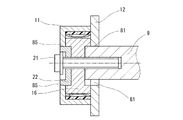
しかし、バルブタイミング調整装置の組付けでは、例えば図7(A)に示すように、ハウジング11、スプロケット12、ベーンロータ16、およびベーンロータに嵌合するブッシュ22をカムシャフト9に固定するとき、ハウジング等の自重によってスプロケット12がカムシャフト9の上部と接触した状態になる。この状態でセンターボルト21を締め付けると、図7(B)に示すように、センターボルト21の軸力でカムシャフト9が圧縮されて径方向に膨張し、カムシャフト9、ベーンロータ16およびブッシュ22に対し、スプロケット12とハウジング11とが一体で矢印100の方向へ移動する。すると、第1軸受部81の上側と第2軸受部85の下側とでこじりを生じ、第1、第2軸受部81、85が円滑に回動しなくなる虞がある。
Such a valve timing adjusting device that receives the driving force of the crankshaft on the sprocket includes a first bearing portion formed by the camshaft and the sprocket, and a second bearing portion formed by the vane rotor and the housing. The inclination of the shaft and the rotating shaft of the vane rotor is prevented.
However, in assembling the valve timing adjusting device, for example, as shown in FIG. 7A, when the
この問題を解決するため、図8に示すように、ベーンロータ16、ハウジング11およびスプロケット12を位置決めする精密冶具41、42を使用してこれ等の構成要素を組み付け、その後、図9に示すように、ハウジング11とカムシャフト9を位置決めする精密冶具43を使用してベーンロータ16とカムシャフト9とを組み付けることが考えられていた。
To solve this problem, as shown in FIG. 8, these components are assembled using
特許文献2では、シール部材を付勢する板ばねによってベーンロータとハウジングとの調芯を行う構造が考えられている。しかし、「第2軸受部を形成していないと、スプロケットの歯の位置を第1摺動部に対してオーバーハングさせた場合、スプロケットとカムシャフトとにこじりを生ずる。このため、スプロケットの歯と第1摺動部とは概ね同一線上としなければならない」、「ベーンロータとハウジングとの摩擦力があるので、板ばねの付勢力をある程度大きくする必要がある」、「各板ばねの合力をベーンロータの中心方向に設定しなければならない」等、スプロケット及び板ばねの設計上の制約があった。
In
本発明の目的は、軸受部の相対回動を確保するバルブタイミング調整装置およびその組付け方法を提供することにある。
本発明の目的は、製造工程を簡素にするバルブタイミング調整装置およびその組付け方法を提供することにある。
An object of the present invention is to provide a valve timing adjusting device that secures relative rotation of a bearing portion and an assembling method thereof.
An object of the present invention is to provide a valve timing adjusting device and an assembling method thereof that simplify the manufacturing process.
請求項1に記載の発明によると、従動軸の径外方向の第1外壁と、スプロケットの軸孔を形成し第1外壁を軸受けする第1内壁とによって第1軸受部が形成される。ベーンロータの径外方向の第2外壁と、第2外壁を軸受けするハウジングの第2内壁とによって第2軸受部が形成される。第1軸受部および第2軸受部の少なくともいずれか一方に形成される変形可能な干渉材は、スプロケットとハウジングとの間に収容されたベーンロータをセンターボルトによって従動軸に固定するとき、変形することでセンターボルトの締め付けの軸力による従動軸の径方向の膨脹を吸収する。これにより、変形可能な干渉材は、従動軸の径方向の膨脹が第1軸受部の径方向の一側に作用する力、および、軸中心に垂直な面に投影したときこの一側と軸中心を挟んで径方向に向き合う第2軸受部の他側に作用する力を吸収する。このため、第1軸受部および第2軸受部のこじりが抑制され、第1軸受部および第2軸受部の相対回動を確保することができる。
ここで、変形可能な干渉材とは、従動軸の膨脹により弾性変形または塑性変形可能であり、相対する部材同士の干渉を防止する部材をいう。
According to the first aspect of the present invention, the first bearing portion is formed by the radially outer first outer wall of the driven shaft and the first inner wall that forms the shaft hole of the sprocket and supports the first outer wall. A second bearing portion is formed by the second outer wall in the radially outward direction of the vane rotor and the second inner wall of the housing that supports the second outer wall. The deformable interference material formed on at least one of the first bearing portion and the second bearing portion is deformed when the vane rotor accommodated between the sprocket and the housing is fixed to the driven shaft by the center bolt. It absorbs the radial expansion of the driven shaft due to the axial force of tightening the center bolt. As a result, the deformable interference member has a force that the expansion in the radial direction of the driven shaft acts on one side in the radial direction of the first bearing portion, and the one side and the shaft when projected on a plane perpendicular to the shaft center. The force acting on the other side of the second bearing portion facing the radial direction across the center is absorbed. For this reason, the twisting of the first bearing portion and the second bearing portion is suppressed, and the relative rotation of the first bearing portion and the second bearing portion can be ensured.
Here, the deformable interference material refers to a member that can be elastically deformed or plastically deformed by expansion of the driven shaft and prevents interference between opposing members.
請求項2に記載の発明によると、第1軸受部および第2軸受部に形成される変形可能な干渉材の厚さの合計は、従動軸の半径の膨張量より大きく形成する。このため、第1軸受部を形成する第1内壁と第1外壁とが直接接触することが回避され、第2軸受部を形成する第2内壁および第2外壁とが直接接触することが回避される。これにより、各軸受部の摩擦が低減し、第1軸受部および第2軸受部の相対回動を確保することができる。
請求項3に記載の発明によると、変形可能な干渉材は、ゴム、シリコン、樹脂、紙、木材、軟質メッキおよび軟質アルマイトからなる群のいずれか1つを含んで形成される。
According to the second aspect of the present invention, the total thickness of the deformable interference members formed in the first bearing portion and the second bearing portion is formed larger than the expansion amount of the radius of the driven shaft. Therefore, direct contact between the first inner wall and the first outer wall forming the first bearing portion is avoided, and direct contact between the second inner wall and the second outer wall forming the second bearing portion is avoided. The Thereby, the friction of each bearing part reduces and the relative rotation of a 1st bearing part and a 2nd bearing part is securable.
According to the invention described in
請求項4に記載の発明によると、脱落可能な表面処理層は、センターボルトの締め付けにより従動軸が径方向に膨張するとき、表面処理層自身が破壊することで、第1軸受部の径方向の一側に作用する力、および、軸中心に垂直な面に投影したときこの一側と軸中心を挟んで径方向に向き合う第2軸受部の他側に作用する力を吸収することができる。
ここで、脱落可能な表面処理層とは、従動軸の膨脹により表面処理層自身が破壊し、脱落または剥離可能な表面処理層をいう。
請求項5記載の発明によると、脱落可能な表面処理層は、二硫化モリブデン、ポリテトラフルオロエチレン、塗装、ポリフッ化エチレンおよびボロンからなる群のいずれか1つを含んで形成される。
According to the invention described in
Here, the surface treatment layer that can be removed refers to a surface treatment layer that can be removed or peeled off by the surface treatment layer itself being destroyed by expansion of the driven shaft.
According to the fifth aspect of the present invention, the removable surface treatment layer includes any one of the group consisting of molybdenum disulfide, polytetrafluoroethylene, paint, polyfluorinated ethylene, and boron.
請求項6記載の発明によると、脱落可能な表面処理層は、作動流体に融解可能な材質である。
請求項7記載の発明によると、ベーンロータは軸方向反従動軸側に筒状のブッシュを備え、フロントプレートはブッシュを通す軸孔を有する。第2外壁はブッシュの外壁であり、第2内壁は前記フロントプレートの軸孔を形成する内壁である。
According to the sixth aspect of the present invention, the removable surface treatment layer is made of a material that can be melted into the working fluid.
According to the seventh aspect of the present invention, the vane rotor includes the cylindrical bush on the axially driven shaft side, and the front plate has the shaft hole through which the bush passes. The second outer wall is an outer wall of the bush, and the second inner wall is an inner wall that forms a shaft hole of the front plate.
請求項8または9に記載の発明によると、変形可能な干渉材または脱落可能な表面処理層は、センターボルトを締め付ける軸力による従動軸の膨張を吸収する。したがって、ハウジング、チェーンスプロケットおよびベーンロータを位置決めする精密冶具、並びにハウジングおよびカムシャフトを位置決めする精密冶具を使用することなしに組付けを行うことで製造工程を簡素にすることができる。
According to the invention described in
以下、本発明の実施形態を図に基づいて説明する。
(第1実施形態)
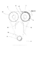
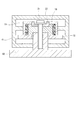
本発明の第1実施形態によるバルブタイミング調整装置を図1〜図4に示す。図3に示すように、駆動力伝達系では、エンジン6の駆動軸としてのクランクシャフト8に固定されるギア98と、従動軸としてのカムシャフト7、9に固定されるギア97、99にチェーン5が巻き掛けられ、クランクシャフト8からカムシャフト7、9に駆動力が伝達される。一方のカムシャフト7は吸気弁93を開閉駆動し、他方のカムシャフト9は排気弁92を開閉駆動する。本実施形態のバルブタイミング調整装置10は、作動流体として作動油を用いる油圧制御式であり、スプロケットのギア97をチェーン5に、ベーンロータをカムシャフト7に接続し、吸気弁93のバルブタイミングを調整する。
Embodiments of the present invention will be described below with reference to the drawings.
(First embodiment)
A valve timing adjusting apparatus according to a first embodiment of the present invention is shown in FIGS. As shown in FIG. 3, in the driving force transmission system, a chain is connected to a
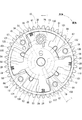
図1および図2に示すように、バルブタイミング調整装置10は、スプロケット12、ハウジング11、ベーンロータ16等を備えている。
スプロケット12は、例えば鉄またはアルミにより焼結または鍛造等によって形成され、軸方向にカムシャフト7を通す軸孔121を有している。
ハウジング11は、例えば鉄またはアルミにより焼結または鍛造等によって形成されている。ハウジング11は、シューハウジング13およびフロントプレート14から構成されている。シューハウジング13は仕切部材としてのシュー131〜134と、環状の周壁130とが一体に形成されている。略台形に形成されたシュー131〜134は周壁130から径内方向に延びており、周壁130の回転方向に略等間隔に設けられている。回転方向に隣接するシュー同士の間隙には扇状の収容室50が形成されている。シューハウジング13およびフロントプレート14は、ボルト19によってスプロケット12と同軸上に固定されている。
As shown in FIGS. 1 and 2, the valve
The
The
ベーンロータ16は、例えば鉄またはアルミにより焼結または鍛造等によって形成され、ハウジング11とスプロケット12との間に相対回動自在に収容されている。ベーンロータ16は、円筒状のロータ60と、ロータ60から径外方向に突出し、周方向に略等間隔に設置される4個のベーン61〜64とを有している。各ベーン61〜64の外径は、周壁130の内径よりも小さく設定されている。また、ロータ60の外径は、各シュー131〜134の内径よりも小さく設定されている。
The
各ベーン61〜64は、各収容室50を、遅角室としての遅角油圧室と進角室としての進角油圧室とに二分している。シュー131とベーン61との間に進角油圧室55が形成され、シュー132とベーン62との間に進角油圧室56が形成され、シュー133とベーン63との間に進角油圧室57が形成され、シュー134とベーン64との間に進角油圧室58が形成されている。シュー132とベーン61との間に遅角油圧室51が形成され、シュー133とベーン62との間に遅角油圧室52が形成され、シュー134とベーン63の間に遅角油圧室53が形成され、シュー131とベーン64の間に遅角油圧室54が形成されている。図2に示す遅角方向、進角方向を表す矢印は、ハウジング11に対するベーンロータ16の遅角方向、進角方向を表している。
Each of the
カムシャフト7およびベーンロータ16の内部には、遅角油路101および進角油路110が形成されている。各遅角油圧室51〜54には遅角油路101から作動油が供給され、各進角油圧室55〜58には進角油路110から作動油が供給される。両油路101、110への作動油の供給および排出を切り換えることでハウジング11に対してベーンロータ16を相対回動し、クランクシャフト8に対するカムシャフト7の位相差を調整する。
A
カムシャフト7は、スプロケット12に形成される軸孔121に挿入されている。カムシャフト7の軸方向端面79とベーンロータ16の軸方向端面69とが当接している。センターボルト21をベーンロータ16のボルト孔68を通しカムシャフト7のねじ穴73に締め付けることで、ベーンロータ16とカムシャフト7とが固定されている。ベーンロータ16とカムシャフト7との回転方向の位置決めは、ロータ60に設けたピン穴66と、カムシャフト7に設けたピン穴72とに位置決めピン18を嵌合することにより成される。
ハウジング11、ベーンロータ16およびカムシャフト7は図1に示す矢印X方向からみて時計方向に回転する。この回転方向を進角方向とする。
The
The
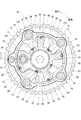
カムシャフト7の径外方向の第1外壁71は、スプロケット12の軸孔121を形成する第1内壁122に軸受されている。カムシャフト7にセンターボルト21を締め付ける前において、第1外壁71と第1内壁122との間には例えば10〜50μmのクリアランスが形成されている。カムシャフト7にセンターボルト21を締め付けるとき、カムシャフト7は軸力で圧縮され、材質、外径および締め付けトルクにより径方向に例えば10〜20μm膨脹する。
ロータ60の径外方向の第2外壁67は、シュー131〜134の径内方向の第2内壁135〜138に軸受されている。第2外壁67と第2内壁135〜138との間には、カムシャフト7にセンターボルト21を締め付ける前において、例えば10〜20μmのクリアランスが形成されている。
第1外壁71と第1内壁122とにより第1軸受部81が形成される。第2外壁67と第2内壁135〜138とにより第2軸受部82が形成される。第1軸受部81および第2軸受部82は、クランクシャフト8からチェーン5を経由してスプロケット12に駆動力を受けるバルブタイミング調整装置10において、ハウジングの回転軸とベーンロータの回転軸との傾きを防いでいる。
The first
The second
A
図4に示すように、第1軸受部81を形成する第1外壁71および第1内壁122のいずれか一方に変形可能な干渉材83が形成されている。干渉材83は、ゴム、シリコン、樹脂、紙、粉砕した木材、銅等の軟質メッキおよび軟質アルマイト等を含んで形成されている。干渉材83は、カムシャフト7にセンターボルト21を締め付けるとき、カムシャフト7が径方向に膨脹する大きさより厚く形成され、カムシャフト7にセンターボルト21を締め付ける前において、全周のうちの薄い場所で例えば20μmより厚く形成されている。
As shown in FIG. 4, a
第2軸受部82を形成する第2外壁67および第2内壁135〜138のいずれか一方には変形可能な干渉材84が形成されている。カムシャフト7にセンターボルト21を締め付ける前において、干渉材84の厚さは例えば20μmに形成されている。なお、第1軸受部81に形成される干渉材83、および第2軸受部82に形成される干渉材84の厚さの合計が、カムシャフト7の半径の膨脹量の大きさより大きく形成されていればよい。
A
シール部材28は、例えば樹脂で形成され、各ベーン61〜64の径外方向の外壁に嵌合している。シール部材28は、それぞれ板ばね29の付勢力により周壁130に向けて付勢されており、各ベーン61〜64の径外方向の外壁と周壁130との間を通じて各進角油圧室55〜58と各遅角油圧室51〜54との間に作動油が漏れることを防止している。
The
ストッパピストン30は、有底円筒状に形成され、ベーン61を回転軸方向に貫通して形成された孔に回転軸方向に往復移動自在に収容されている。ストッパピストン30は、内部にスプリング34を収容している。スプリング34は、ストッパピストン30をスプロケット12側へ付勢している。スプロケット12のベーン61側に形成された凹部に嵌合リング36が圧入保持されている。
The
ストッパピストン30のスプロケット12側に形成された圧力室32、およびストッパピストン30の外周に形成された圧力室33に供給される作動油の圧力は嵌合リング36からストッパピストン30が抜け出す方向に働く。圧力室32は進角油圧室55と連通し、圧力室33は遅角油圧室51と連通している。ストッパピストン30の先端部は、ハウジング11に対し最遅角位置にベーンロータ16が位置するとき、嵌合リング36に嵌合可能である。ストッパピストン30が嵌合リング36に嵌合した状態においてハウジング11に対するベーンロータ16の相対回動は拘束される。
The pressure of the hydraulic oil supplied to the
次に、バルブタイミング調整装置10の組付け工程について説明する。
<干渉材形成工程>
第1軸受部81および第2軸受部82の少なくともいずれか一方に変形可能な干渉材83、84を形成する。
第1軸受部81に干渉材83を形成する場合を説明する。ゴム、シリコンおよび樹脂を含む干渉材83の場合は、第1外壁71および第1内壁122のいずれか一方に、ゴム、シリコンおよび樹脂を塗り付け、吹き付け、どぶ付け等、塗布することで形成する。紙および粉砕した木材を含む干渉材の場合は、第1外壁71および第1内壁122のいずれか一方に、紙および粉砕した木材を接着等することで形成する。軟質メッキによる干渉材83の場合は、第1外壁71および第1内壁122のいずれか一方を例えば銅等による電気メッキをすることで形成する。軟質アルマイトによる干渉材83場合は、アルミの第1外壁71および第1内壁122のいずれか一方を陽極酸化処理することで形成する。上述の工程後、干渉材83を形成した第1外壁71または第1内壁122に所定の径を有する筒状の部材を通すことで干渉材83の厚さを調整する。
第2軸受部82に変形可能な干渉材84を形成する場合、第2外壁67および第2内壁135〜138のいずれか一方に上述の工程を行う。
Next, the assembly process of the valve
<Interference material formation process>
A case where the
When the
<ベーンロータ組付け工程>
スプロケット12を、カムシャフトに相当する冶具(図8の下側の冶具42参照)に挿入する。次に、スプロケット12の上に、ベーンロータ16、シューハウジング13を設置し、フロントプレート14を被せる。ベーンロータ16、シューハウジング13およびフロントプレート14をボルト19で固定する。
<Vane rotor assembly process>
The
<カムシャフト取付け工程>
ベーンロータ組付け工程後、スプロケット12の軸孔121にカムシャフト7を挿入する。カムシャフト7の軸方向端面79と、ベーンロータ16の軸方向端面69とを当接する。フロントプレート14側からセンターボルト21をベーンロータ16のボルト孔68に通し、カムシャフト7のねじ穴73に締め付ける。
このとき、第1軸受部81および第2軸受部82の少なくともいずれか一方に形成された干渉材83、84が変形し、センターボルト21の締め付けの軸力によるカムシャフトの径方向の膨張を吸収する。このため、ハウジング11、スプロケット12およびベーンロータ16を位置決めする精密冶具、並びにハウジング11およびカムシャフト7を位置決めする精密冶具を使用することなしに組付けを行い、製造工程を簡素にすることができる。
<Camshaft installation process>
After the vane rotor assembly process, the
At this time, the
次に、バルブタイミング調整装置10の作動を説明する。なお、図1および図2は、エンジン始動前、すなわちエンジン6が停止している時のバルブタイミング調整装置10の状態を示している。
<エンジン始動時>
エンジン6が停止している状態ではストッパピストン30は嵌合リング36に入り込んでいる。エンジン6を始動した直後の状態では、遅角油圧室51〜54、進角油圧室55〜58、および圧力室32、33に油圧ポンプ1から十分に作動油が供給されない。このため、ストッパピストン30は嵌合リング36に入り込んだ状態を維持し、クランクシャフト8に対しカムシャフト7は最遅角位置に保持されている。これにより、作動油が各油圧室に供給されるまでの間、カムシャフト7が受けるトルク変動によりハウジング11とベーンロータ16との衝突による打音の発生が防止される。
Next, the operation of the valve
<When starting the engine>
When the
<エンジン始動後>
エンジン始動後、油圧ポンプ1から作動油が十分に供給されると、圧力室32、33に供給される油圧によりストッパピストン30が嵌合リング36から抜け出し、ハウジング11に対しベーンロータ16は相対回動自在となる。各遅角油圧室51〜54および各進角油圧室55〜58に加わる油圧を制御することにより、クランクシャフト8に対するカムシャフト7の位相差が調整可能となる。
<After starting the engine>
When the hydraulic oil is sufficiently supplied from the
<遅角作動時>
バルブタイミング調整装置10を遅角制御するとき、電子制御装置(ECU)4は、切換弁3に供給する駆動電流を制御する。切換弁3は、油圧ポンプ1と遅角油路101とを接続し、進角油路110とオイルパン2とを接続する。油圧ポンプ1から吐出される作動油は、遅角油路101を経由し、遅角油圧室51〜54に供給される。進角油圧室55〜58の作動油は進角油路110を経由し、オイルパン2に排出される。遅角油圧室51〜54の油圧がベーン61〜64に作用し、ベーンロータ16を遅角方向に付勢するトルクを発生する。これにより、ベーンロータ16は、ハウジング11に対して遅角方向に回動する。
<At retarded angle operation>
When the valve
<進角作動時>
バルブタイミング調整装置10を進角制御するとき、ECU4は、切換弁3に供給する駆動電流を制御する。切換弁3は、油圧ポンプ1と進角油路110とを接続し、遅角油路101とオイルパン2とを接続する。油圧ポンプ1から吐出される作動油は、進角油路110を経由し、進角油圧室55〜58に供給される。遅角油圧室51〜54の作動油は、遅角油路101を経由し、オイルパン2に排出される。進角油圧室55〜58の油圧は、ベーン61〜64に作用し、ベーンロータ16を進角方向に付勢するトルクを発生する。これにより、ベーンロータ16は、ハウジング11に対し進角方向に回動する。
<Advance angle operation>
When the valve
<中間保持作動時>
ベーンロータ16が目標位相に到達すると、ECU4は切換弁3に供給する駆動電流のデューティ比を制御する。切換弁3は、油圧ポンプ1と、遅角油路101および進角油路110との接続を遮断し、遅角油圧室51〜54および進角油圧室55〜58からオイルパン2に作動油が排出されることを規制する。このため、ベーンロータ16は目標位相に保持される。
<Intermediate holding operation>
When the
<エンジン停止時作動>
バルブタイミング調整装置10の作動中にエンジン停止が指示されると、ベーンロータ16は、上記遅角作動時と同様の作動によりハウジング11に対して遅角方向に回転し、最遅角位置で回動が停止する。この状態において、ECU4は、油圧ポンプ1の作動を停止するとともに、切換弁3によって遅角油路101とオイルパン2とを接続する。これにより、圧力室33の圧力が低下し、ストッパピストン30はスプリング34の付勢力により嵌合リング36へ入り込む。
<Operation when the engine is stopped>
When the engine stop is instructed during the operation of the valve
本実施形態では、センターボルト21の締め付けの軸力によりカムシャフト7が圧縮されて径方向に膨張するとき、変形可能な干渉材83、84が変形することで、第1軸受部81の径方向の一側に加わる力、および、軸中心に垂直な面に投影したときこの一側と軸中心を挟んで径方向に向き合う第2軸受部82の他側に加わる力を吸収する。そして、変形可能な干渉材は、第1軸受部81を形成する第1内壁122と第1外壁71とが直接接触すること、および第2軸受部82を形成する第2内壁135〜138と第2外壁67とが直接接触することを防止し、第1、第2軸受部81、82の摩擦を低減する。したがって、第1軸受部81の径方向の一側に加わる力と、第2軸受部82の他側に加わる力とにより生じるこじりが抑制され、第1軸受部81および第2軸受部82の相対回動を確保することができる。
In the present embodiment, when the
(第2実施形態)
第2実施形態は、第1実施形態の変形例である。第1軸受部81を形成する第1外壁71および第1内壁122のいずれか一方には、第1実施形態の変形可能な干渉材に代えて、脱落可能な表面処理層が形成される。表面処理層は、二硫化モリブデン、ポリテトラフルオロエチレン(PTFE)、塗装、ポリフッ化エチレンおよびボロン等を含んで形成されている。
第2軸受部82を形成する第2外壁67および第2内壁135〜138のいずれか一方には脱落可能な表面処理層が形成されている。第1軸受部81に形成される表面処理層、および第2軸受部82に形成される表面処理層の厚さの合計は、センターボルト21を締め付けるときにおけるカムシャフト7の半径の膨脹量の大きさより大きく形成されている。
(Second Embodiment)
The second embodiment is a modification of the first embodiment. Either one of the first
A removable surface treatment layer is formed on one of the second
次に、第2実施形態のバルブタイミング調整装置の組付け工程における表面処理層の形成工程について説明する。
第1軸受部81および第2軸受部82の少なくともいずれか一方に脱落可能な表面処理層を形成する。第1軸受部81に表面処理層を形成する場合を説明する。二硫化モリブデンを含む表面処理層の場合は、第1外壁71および第1内壁122のいずれか一方に、二硫化モリブデンシールの貼り付け、塗布等することで形成する。PTFE、塗装、ポリフッ化エチレンおよびボロンを含む表面処理層の場合は、第1外壁71および第1内壁122のいずれか一方に、塗布等することで形成する。上述の工程後、表面処理層を形成した第1外壁71または第1内壁122に所定の径を有する筒状の部材を通すことで表面処理層の厚さを調整する。
第2軸受部82に脱落可能な表面処理層を形成する場合、表面処理層を形成した第2外壁67または第2内壁135〜138に上述の工程を行う。
Next, the formation process of the surface treatment layer in the assembly | attachment process of the valve timing adjustment apparatus of 2nd Embodiment is demonstrated.
A removable surface treatment layer is formed on at least one of the
When the surface treatment layer that can be removed is formed on the
本実施形態では、第1軸受部81および第2軸受部82の少なくともいずれか一方に脱落可能な表面処理層が形成されているので、センターボルト21の締め付けによりカムシャフトが径方向に膨張するとき、表面処理層自身が破壊することで、第1軸受部81の径方向の一側に加わる力、および、軸中心に垂直な面に投影したときこの一側と軸中心を挟んで径方向に向き合う第2軸受部82の他側に加わる力を吸収することができる。
In this embodiment, since a removable surface treatment layer is formed on at least one of the
(第3実施形態)
第3実施形態によるバルブタイミング調整装置を図5および図6に示す。第1実施形態と実質的に同一の構成については同一の符号を付して説明を省略する。
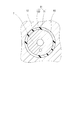
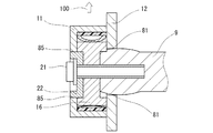
第3実施形態のバルブタイミング調整装置20では、ベーンロータ16の軸方向反カムシャフト側に凹部65が形成され、この凹部65に有底筒状に形成されたブッシュ22が嵌合している。ブッシュ22は、フロントプレート14に形成された軸孔15に通っている。ブッシュ22の径外方向の外壁23は、フロントプレート14の軸孔15を形成する内壁141に軸受されている。外壁23と内壁141との間には、カムシャフト7にセンターボルト21を締め付ける前において、例えば10〜20μmのクリアランスが形成されている。本実施形態では、外壁23と内壁141とにより第2軸受部85が形成されている。
(Third embodiment)
A valve timing adjusting apparatus according to a third embodiment is shown in FIGS. Components substantially the same as those of the first embodiment are denoted by the same reference numerals and description thereof is omitted.
In the valve
第2軸受部85を形成するブッシュ22の径外方向の外壁23およびフロントプレート14の軸孔15を形成する内壁141のいずれか一方には変形可能な干渉材84が形成されている。カムシャフト7にセンターボルト21を締め付ける前において、干渉材84の厚さは例えば20μmに形成されている。第1軸受部81に形成される干渉材83、および第2軸受部82に形成される干渉材84の厚さの合計が、カムシャフト7の半径の膨脹より大きく形成されていればよい。
バルブタイミング調整装置20の組付け工程、および作動については第1実施形態と実質的に同一であるため説明を省略する。
A
Since the assembly process and operation of the valve
本実施形態では、センターボルト21の締め付けによりカムシャフト7が径方向に膨張するとき、変形可能な干渉材83、84が変形することで、第1軸受部81の径方向の一側に加わる力、および、軸中心に垂直な面に投影したときこの一側と軸中心を挟んで径方向に向き合う第2軸受部85の他側に加わる力を吸収する。そして、変形可能な干渉材は、第1軸受部81を形成する第1内壁122と第1外壁71とが直接接触すること、および第2軸受部85を形成するブッシュ22の径外方向の外壁23とフロントプレート14の軸孔15を形成する内壁141とが直接接触することを防止し、第1、第2軸受部81、85の摩擦を低減する。したがって、第1軸受部81の径方向の一側と、第2軸受部85の他側に加わる力とにより生じるこじりが抑制され、第1軸受部81および第2軸受部85の相対回動を確保することができる。
In the present embodiment, when the
(他の実施形態)
上記第2実施形態では、第1軸受部81および第2軸受部82の少なくともいずれか一方に、二硫化モリブデン等を含んでなる脱落可能な表面処理層を形成した。これに対し、第1軸受部81および第2軸受部82の少なくともいずれか一方に、作動流体に融解可能な表面処理層を形成しても良い。作動流体に融解可能な表面処理層は、例えば蝋等を含んで形成される。
上記第3実施形態では、第1軸受部81および第2軸受部85の少なくともいずれか一方に、変形可能な干渉材を形成した。これに対し、第1軸受部81および第2軸受部85の少なくともいずれか一方に、脱落可能な表面処理層または作動流体に融解可能な表面処理層を形成しても良い。
上記実施形態では、内燃機関の吸気弁を制御するバルブタイミング調整装置について説明した。これに対し、内燃機関の排気弁を制御するバルブタイミング調整装置に本発明を適用してもよい。
このように、本発明は上記実施形態に限定されるものではなく、その要旨を逸脱しない範囲で、上記複数の実施形態を組み合わせることに加え、他の種々の実施形態に適用可能である。
(Other embodiments)
In the second embodiment, a removable surface treatment layer containing molybdenum disulfide or the like is formed on at least one of the
In the third embodiment, a deformable interference material is formed on at least one of the
In the above embodiment, the valve timing adjusting device that controls the intake valve of the internal combustion engine has been described. On the other hand, you may apply this invention to the valve timing adjustment apparatus which controls the exhaust valve of an internal combustion engine.
As described above, the present invention is not limited to the above-described embodiment, and can be applied to other various embodiments in addition to combining the plurality of embodiments without departing from the gist thereof.
6:エンジン(内燃機関)、7:カムシャフト(従動軸)、8:クランクシャフト(駆動軸)、10:バルブタイミング調整装置、11:ハウジング、12:スプロケット、14:フロントプレート、16:ベーンロータ、21:センターボルト、50:収容室、51、52、53、54:遅角油圧室(遅角室)、55、56、57、58:進角油圧室、67:第2外壁、71:第1外壁、81:第1軸受部、82:第2軸受部、83、84:干渉材、92:吸気弁、93:排気弁、121:軸孔、122:第1内壁、130:周壁、131、132、133、134:シュー(仕切部材)、135、136、137、138:第2内壁
6: engine (internal combustion engine), 7: camshaft (driven shaft), 8: crankshaft (drive shaft), 10: valve timing adjusting device, 11: housing, 12: sprocket, 14: front plate, 16: vane rotor, 21: Center bolt, 50: Storage chamber, 51, 52, 53, 54: Retarded hydraulic chamber (retarded chamber), 55, 56, 57, 58: Advanced hydraulic chamber, 67: Second outer wall, 71:
Claims (9)
前記従動軸を通す軸孔を有し、前記駆動軸の駆動力を伝達されて回転するスプロケットと、
環状の周壁、前記周壁から径内方向に延びて回転方向に所定角度範囲で設けられる仕切部材、および前記周壁の軸方向一端に接続するフロントプレートを有し、前記周壁の軸方向他端を前記スプロケットと固定するハウジングと、
回転方向に隣接する前記仕切部材の間に形成される収容室を仕切って進角室および遅角室を形成し、前記進角室および前記遅角室に供給される作動流体の圧力により遅角方向または進角方向に駆動され、前記ハウジングに対して相対回動するベーンロータと、
前記従動軸の径外方向の第1外壁と前記スプロケットの前記軸孔を形成し前記第1外壁を軸受けする第1内壁とによって形成される第1軸受部と、
前記ベーンロータの径外方向の第2外壁と前記第2外壁を軸受けする前記ハウジングの第2内壁とによって形成される第2軸受部と、
前記第1軸受部および前記第2軸受部の少なくともいずれか一方に形成され、
前記スプロケットと前記ハウジングとの間に収容された前記ベーンロータをセンターボルトによって前記従動軸に固定するとき、前記センターボルトの締め付けの軸力による前記従動軸の径方向の膨脹を吸収する変形可能な干渉材と、
を備えることを特徴とするバルブタイミング調整装置。 Provided in a driving force transmission system for transmitting a driving force from a driving shaft of an internal combustion engine to a driven shaft that opens and closes at least one of an intake valve and an exhaust valve, and adjusts an opening / closing timing of at least one of the intake valve and the exhaust valve In the valve timing adjustment device,
A sprocket having a shaft hole through which the driven shaft passes, and rotating by being transmitted with a driving force of the driving shaft;
An annular peripheral wall, a partition member extending inwardly from the peripheral wall and provided in a predetermined angle range in the rotational direction, and a front plate connected to one axial end of the peripheral wall, the other axial end of the peripheral wall being A housing fixed to the sprocket;
A storage chamber formed between the partition members adjacent to each other in the rotation direction is partitioned to form an advance chamber and a retard chamber, and retarded by the pressure of the working fluid supplied to the advance chamber and the retard chamber A vane rotor that is driven in a direction or an advance direction and rotates relative to the housing;
A first bearing portion formed by a first outer wall in a radially outward direction of the driven shaft and a first inner wall that forms the shaft hole of the sprocket and receives the first outer wall;
A second bearing portion formed by a radially outer second outer wall of the vane rotor and a second inner wall of the housing bearing the second outer wall;
Formed in at least one of the first bearing portion and the second bearing portion;
When the vane rotor accommodated between the sprocket and the housing is fixed to the driven shaft by a center bolt, the deformable interference that absorbs the radial expansion of the driven shaft due to the axial force of the center bolt tightening. Material,
A valve timing adjusting device comprising:
前記変形可能な干渉材に代えて脱落可能な表面処理層を備えることを特徴とするバルブタイミング調整装置。 The valve timing adjusting device according to claim 1 or 2,
A valve timing adjusting device comprising a surface treatment layer that can be removed in place of the deformable interference material.
前記フロントプレートは前記ブッシュを通す軸孔を有し、
前記第2外壁は前記ブッシュの外壁であり、前記第2内壁は前記フロントプレートの前記軸孔を形成する内壁であることを特徴とする請求項1〜6のいずれか一項に記載のバルブタイミング調整装置。 The vane rotor is provided with a cylindrical bush on the axial anti-driven shaft side,
The front plate has a shaft hole through which the bush passes,
The valve timing according to any one of claims 1 to 6, wherein the second outer wall is an outer wall of the bush, and the second inner wall is an inner wall that forms the shaft hole of the front plate. Adjustment device.
前記第1軸受部および前記第2軸受部の少なくともいずれか一方に前記変形可能な干渉材を形成する工程と、
前記ハウジングと前記スプロケットとの間に前記ベーンロータを収容し、前記スプロケットと前記ハウジングとを固定する工程と、
前記スプロケットの前記軸孔に前記従動軸を挿入し、前記従動軸の軸方向端面と前記ベーンロータの軸方向端面とを当接し、前記センターボルトを締め付けて前記従動軸と前記ベーンロータとを固定する工程と、を含むことを特徴とするバルブタイミング調整装置の組付け方法。 In the assembly method of the valve timing adjusting device according to claim 1,
Forming the deformable interference material on at least one of the first bearing portion and the second bearing portion;
Accommodating the vane rotor between the housing and the sprocket, and fixing the sprocket and the housing;
Inserting the driven shaft into the shaft hole of the sprocket, contacting the axial end surface of the driven shaft with the axial end surface of the vane rotor, and fastening the center bolt to fix the driven shaft and the vane rotor. And a method for assembling the valve timing adjusting device.
前記変形可能な干渉材を形成することに代えて脱落可能な表面処理層を形成することを特徴とするバルブタイミング調整装置の組付け方法。 In the assembly method of the valve timing adjusting device according to claim 8,
A method for assembling a valve timing adjusting device, wherein a removable surface treatment layer is formed instead of forming the deformable interference material.
Priority Applications (1)
| Application Number | Priority Date | Filing Date | Title |
|---|---|---|---|
| JP2008205361A JP5040852B2 (en) | 2008-08-08 | 2008-08-08 | Valve timing adjustment device |
Applications Claiming Priority (1)
| Application Number | Priority Date | Filing Date | Title |
|---|---|---|---|
| JP2008205361A JP5040852B2 (en) | 2008-08-08 | 2008-08-08 | Valve timing adjustment device |
Publications (2)
| Publication Number | Publication Date |
|---|---|
| JP2010038136A true JP2010038136A (en) | 2010-02-18 |
| JP5040852B2 JP5040852B2 (en) | 2012-10-03 |
Family
ID=42010929
Family Applications (1)
| Application Number | Title | Priority Date | Filing Date |
|---|---|---|---|
| JP2008205361A Expired - Fee Related JP5040852B2 (en) | 2008-08-08 | 2008-08-08 | Valve timing adjustment device |
Country Status (1)
| Country | Link |
|---|---|
| JP (1) | JP5040852B2 (en) |
Citations (5)
| Publication number | Priority date | Publication date | Assignee | Title |
|---|---|---|---|---|
| JPH10148109A (en) * | 1996-11-19 | 1998-06-02 | Toyota Motor Corp | Valve system for internal combustion engine |
| JPH1181925A (en) * | 1997-09-08 | 1999-03-26 | Denso Corp | Valve timing adjusting device for internal combustion engine |
| JP2002256824A (en) * | 2001-02-27 | 2002-09-11 | Ntn Corp | Valve timing adjusting device of engine |
| JP2003106114A (en) * | 2001-09-28 | 2003-04-09 | Hitachi Unisia Automotive Ltd | Valve timing control device of internal combustion engine |
| JP2004060571A (en) * | 2002-07-30 | 2004-02-26 | Aisin Seiki Co Ltd | Valve opening/closing timing control device |
-
2008
- 2008-08-08 JP JP2008205361A patent/JP5040852B2/en not_active Expired - Fee Related
Patent Citations (5)
| Publication number | Priority date | Publication date | Assignee | Title |
|---|---|---|---|---|
| JPH10148109A (en) * | 1996-11-19 | 1998-06-02 | Toyota Motor Corp | Valve system for internal combustion engine |
| JPH1181925A (en) * | 1997-09-08 | 1999-03-26 | Denso Corp | Valve timing adjusting device for internal combustion engine |
| JP2002256824A (en) * | 2001-02-27 | 2002-09-11 | Ntn Corp | Valve timing adjusting device of engine |
| JP2003106114A (en) * | 2001-09-28 | 2003-04-09 | Hitachi Unisia Automotive Ltd | Valve timing control device of internal combustion engine |
| JP2004060571A (en) * | 2002-07-30 | 2004-02-26 | Aisin Seiki Co Ltd | Valve opening/closing timing control device |
Also Published As
| Publication number | Publication date |
|---|---|
| JP5040852B2 (en) | 2012-10-03 |
Similar Documents
| Publication | Publication Date | Title |
|---|---|---|
| US9422836B2 (en) | Valve timing control apparatus | |
| JP6417788B2 (en) | Valve timing adjustment system and manufacturing method thereof | |
| US6405695B2 (en) | Valve timing adjuster for internal combustion engine | |
| JP4379730B2 (en) | Valve timing control device | |
| WO2006095532A1 (en) | Valve opening/closing timing controller | |
| JP2009185766A (en) | Valve timing adjusting device | |
| JP2006220096A (en) | Valve timing controller of internal combustion engine and method of installing the same | |
| JP2005061261A (en) | Variable valve system for internal combustion engine | |
| US20090071424A1 (en) | Valve timing control apparatus | |
| JP2009185719A (en) | Valve timing regulating device | |
| JP6558470B2 (en) | Valve timing adjustment system | |
| JP2006299891A (en) | Driving force transmission device and valve timing adjusting device for internal combustion engine | |
| JP2006183590A (en) | Valve timing adjusting device | |
| JP5071408B2 (en) | Valve timing adjusting device and manufacturing method thereof | |
| JP5920632B2 (en) | Valve timing adjustment device | |
| JP5040852B2 (en) | Valve timing adjustment device | |
| JP2007127057A (en) | Mounting structure for valve timing adjusting device | |
| JP5057232B2 (en) | Valve timing adjusting device and manufacturing method thereof | |
| US20160123197A1 (en) | Valve timing controller | |
| JP2008144590A (en) | Valve timing adjusting device | |
| JP4217977B2 (en) | Valve timing adjustment device | |
| JP7001023B2 (en) | Valve timing adjuster | |
| WO2019088250A1 (en) | Valve timing adjustment device | |
| JP5532338B2 (en) | Valve timing adjustment device | |
| JP2000130117A (en) | Valve opening and closing time control device |
Legal Events
| Date | Code | Title | Description |
|---|---|---|---|
| A621 | Written request for application examination |
Free format text: JAPANESE INTERMEDIATE CODE: A621 Effective date: 20100908 |
|
| A977 | Report on retrieval |
Free format text: JAPANESE INTERMEDIATE CODE: A971007 Effective date: 20111018 |
|
| A131 | Notification of reasons for refusal |
Free format text: JAPANESE INTERMEDIATE CODE: A131 Effective date: 20111021 |
|
| A521 | Request for written amendment filed |
Free format text: JAPANESE INTERMEDIATE CODE: A523 Effective date: 20111206 |
|
| TRDD | Decision of grant or rejection written | ||
| A01 | Written decision to grant a patent or to grant a registration (utility model) |
Free format text: JAPANESE INTERMEDIATE CODE: A01 Effective date: 20120612 |
|
| A01 | Written decision to grant a patent or to grant a registration (utility model) |
Free format text: JAPANESE INTERMEDIATE CODE: A01 |
|
| A61 | First payment of annual fees (during grant procedure) |
Free format text: JAPANESE INTERMEDIATE CODE: A61 Effective date: 20120625 |
|
| R151 | Written notification of patent or utility model registration |
Ref document number: 5040852 Country of ref document: JP Free format text: JAPANESE INTERMEDIATE CODE: R151 |
|
| FPAY | Renewal fee payment (event date is renewal date of database) |
Free format text: PAYMENT UNTIL: 20150720 Year of fee payment: 3 |
|
| R250 | Receipt of annual fees |
Free format text: JAPANESE INTERMEDIATE CODE: R250 |
|
| R250 | Receipt of annual fees |
Free format text: JAPANESE INTERMEDIATE CODE: R250 |
|
| R250 | Receipt of annual fees |
Free format text: JAPANESE INTERMEDIATE CODE: R250 |
|
| R250 | Receipt of annual fees |
Free format text: JAPANESE INTERMEDIATE CODE: R250 |
|
| R250 | Receipt of annual fees |
Free format text: JAPANESE INTERMEDIATE CODE: R250 |
|
| R250 | Receipt of annual fees |
Free format text: JAPANESE INTERMEDIATE CODE: R250 |
|
| LAPS | Cancellation because of no payment of annual fees |