JP2010036776A - Charging control method and device for battery for vehicle - Google Patents
Charging control method and device for battery for vehicle Download PDFInfo
- Publication number
- JP2010036776A JP2010036776A JP2008203406A JP2008203406A JP2010036776A JP 2010036776 A JP2010036776 A JP 2010036776A JP 2008203406 A JP2008203406 A JP 2008203406A JP 2008203406 A JP2008203406 A JP 2008203406A JP 2010036776 A JP2010036776 A JP 2010036776A
- Authority
- JP
- Japan
- Prior art keywords
- battery
- engine
- fuel
- charging
- vehicle
- Prior art date
- Legal status (The legal status is an assumption and is not a legal conclusion. Google has not performed a legal analysis and makes no representation as to the accuracy of the status listed.)
- Granted
Links
Images


Classifications
-
- B—PERFORMING OPERATIONS; TRANSPORTING
- B60—VEHICLES IN GENERAL
- B60L—PROPULSION OF ELECTRICALLY-PROPELLED VEHICLES; SUPPLYING ELECTRIC POWER FOR AUXILIARY EQUIPMENT OF ELECTRICALLY-PROPELLED VEHICLES; ELECTRODYNAMIC BRAKE SYSTEMS FOR VEHICLES IN GENERAL; MAGNETIC SUSPENSION OR LEVITATION FOR VEHICLES; MONITORING OPERATING VARIABLES OF ELECTRICALLY-PROPELLED VEHICLES; ELECTRIC SAFETY DEVICES FOR ELECTRICALLY-PROPELLED VEHICLES
- B60L15/00—Methods, circuits, or devices for controlling the traction-motor speed of electrically-propelled vehicles
- B60L15/20—Methods, circuits, or devices for controlling the traction-motor speed of electrically-propelled vehicles for control of the vehicle or its driving motor to achieve a desired performance, e.g. speed, torque, programmed variation of speed
-
- B—PERFORMING OPERATIONS; TRANSPORTING
- B60—VEHICLES IN GENERAL
- B60L—PROPULSION OF ELECTRICALLY-PROPELLED VEHICLES; SUPPLYING ELECTRIC POWER FOR AUXILIARY EQUIPMENT OF ELECTRICALLY-PROPELLED VEHICLES; ELECTRODYNAMIC BRAKE SYSTEMS FOR VEHICLES IN GENERAL; MAGNETIC SUSPENSION OR LEVITATION FOR VEHICLES; MONITORING OPERATING VARIABLES OF ELECTRICALLY-PROPELLED VEHICLES; ELECTRIC SAFETY DEVICES FOR ELECTRICALLY-PROPELLED VEHICLES
- B60L2210/00—Converter types
- B60L2210/30—AC to DC converters
-
- B—PERFORMING OPERATIONS; TRANSPORTING
- B60—VEHICLES IN GENERAL
- B60L—PROPULSION OF ELECTRICALLY-PROPELLED VEHICLES; SUPPLYING ELECTRIC POWER FOR AUXILIARY EQUIPMENT OF ELECTRICALLY-PROPELLED VEHICLES; ELECTRODYNAMIC BRAKE SYSTEMS FOR VEHICLES IN GENERAL; MAGNETIC SUSPENSION OR LEVITATION FOR VEHICLES; MONITORING OPERATING VARIABLES OF ELECTRICALLY-PROPELLED VEHICLES; ELECTRIC SAFETY DEVICES FOR ELECTRICALLY-PROPELLED VEHICLES
- B60L2210/00—Converter types
- B60L2210/40—DC to AC converters
-
- B—PERFORMING OPERATIONS; TRANSPORTING
- B60—VEHICLES IN GENERAL
- B60L—PROPULSION OF ELECTRICALLY-PROPELLED VEHICLES; SUPPLYING ELECTRIC POWER FOR AUXILIARY EQUIPMENT OF ELECTRICALLY-PROPELLED VEHICLES; ELECTRODYNAMIC BRAKE SYSTEMS FOR VEHICLES IN GENERAL; MAGNETIC SUSPENSION OR LEVITATION FOR VEHICLES; MONITORING OPERATING VARIABLES OF ELECTRICALLY-PROPELLED VEHICLES; ELECTRIC SAFETY DEVICES FOR ELECTRICALLY-PROPELLED VEHICLES
- B60L2240/00—Control parameters of input or output; Target parameters
- B60L2240/10—Vehicle control parameters
- B60L2240/12—Speed
-
- B—PERFORMING OPERATIONS; TRANSPORTING
- B60—VEHICLES IN GENERAL
- B60L—PROPULSION OF ELECTRICALLY-PROPELLED VEHICLES; SUPPLYING ELECTRIC POWER FOR AUXILIARY EQUIPMENT OF ELECTRICALLY-PROPELLED VEHICLES; ELECTRODYNAMIC BRAKE SYSTEMS FOR VEHICLES IN GENERAL; MAGNETIC SUSPENSION OR LEVITATION FOR VEHICLES; MONITORING OPERATING VARIABLES OF ELECTRICALLY-PROPELLED VEHICLES; ELECTRIC SAFETY DEVICES FOR ELECTRICALLY-PROPELLED VEHICLES
- B60L2240/00—Control parameters of input or output; Target parameters
- B60L2240/10—Vehicle control parameters
- B60L2240/36—Temperature of vehicle components or parts
-
- B—PERFORMING OPERATIONS; TRANSPORTING
- B60—VEHICLES IN GENERAL
- B60L—PROPULSION OF ELECTRICALLY-PROPELLED VEHICLES; SUPPLYING ELECTRIC POWER FOR AUXILIARY EQUIPMENT OF ELECTRICALLY-PROPELLED VEHICLES; ELECTRODYNAMIC BRAKE SYSTEMS FOR VEHICLES IN GENERAL; MAGNETIC SUSPENSION OR LEVITATION FOR VEHICLES; MONITORING OPERATING VARIABLES OF ELECTRICALLY-PROPELLED VEHICLES; ELECTRIC SAFETY DEVICES FOR ELECTRICALLY-PROPELLED VEHICLES
- B60L2240/00—Control parameters of input or output; Target parameters
- B60L2240/40—Drive Train control parameters
- B60L2240/42—Drive Train control parameters related to electric machines
- B60L2240/423—Torque
-
- B—PERFORMING OPERATIONS; TRANSPORTING
- B60—VEHICLES IN GENERAL
- B60L—PROPULSION OF ELECTRICALLY-PROPELLED VEHICLES; SUPPLYING ELECTRIC POWER FOR AUXILIARY EQUIPMENT OF ELECTRICALLY-PROPELLED VEHICLES; ELECTRODYNAMIC BRAKE SYSTEMS FOR VEHICLES IN GENERAL; MAGNETIC SUSPENSION OR LEVITATION FOR VEHICLES; MONITORING OPERATING VARIABLES OF ELECTRICALLY-PROPELLED VEHICLES; ELECTRIC SAFETY DEVICES FOR ELECTRICALLY-PROPELLED VEHICLES
- B60L2240/00—Control parameters of input or output; Target parameters
- B60L2240/40—Drive Train control parameters
- B60L2240/44—Drive Train control parameters related to combustion engines
- B60L2240/441—Speed
-
- B—PERFORMING OPERATIONS; TRANSPORTING
- B60—VEHICLES IN GENERAL
- B60L—PROPULSION OF ELECTRICALLY-PROPELLED VEHICLES; SUPPLYING ELECTRIC POWER FOR AUXILIARY EQUIPMENT OF ELECTRICALLY-PROPELLED VEHICLES; ELECTRODYNAMIC BRAKE SYSTEMS FOR VEHICLES IN GENERAL; MAGNETIC SUSPENSION OR LEVITATION FOR VEHICLES; MONITORING OPERATING VARIABLES OF ELECTRICALLY-PROPELLED VEHICLES; ELECTRIC SAFETY DEVICES FOR ELECTRICALLY-PROPELLED VEHICLES
- B60L2240/00—Control parameters of input or output; Target parameters
- B60L2240/40—Drive Train control parameters
- B60L2240/44—Drive Train control parameters related to combustion engines
- B60L2240/443—Torque
-
- B—PERFORMING OPERATIONS; TRANSPORTING
- B60—VEHICLES IN GENERAL
- B60L—PROPULSION OF ELECTRICALLY-PROPELLED VEHICLES; SUPPLYING ELECTRIC POWER FOR AUXILIARY EQUIPMENT OF ELECTRICALLY-PROPELLED VEHICLES; ELECTRODYNAMIC BRAKE SYSTEMS FOR VEHICLES IN GENERAL; MAGNETIC SUSPENSION OR LEVITATION FOR VEHICLES; MONITORING OPERATING VARIABLES OF ELECTRICALLY-PROPELLED VEHICLES; ELECTRIC SAFETY DEVICES FOR ELECTRICALLY-PROPELLED VEHICLES
- B60L2240/00—Control parameters of input or output; Target parameters
- B60L2240/40—Drive Train control parameters
- B60L2240/44—Drive Train control parameters related to combustion engines
- B60L2240/445—Temperature
-
- B—PERFORMING OPERATIONS; TRANSPORTING
- B60—VEHICLES IN GENERAL
- B60L—PROPULSION OF ELECTRICALLY-PROPELLED VEHICLES; SUPPLYING ELECTRIC POWER FOR AUXILIARY EQUIPMENT OF ELECTRICALLY-PROPELLED VEHICLES; ELECTRODYNAMIC BRAKE SYSTEMS FOR VEHICLES IN GENERAL; MAGNETIC SUSPENSION OR LEVITATION FOR VEHICLES; MONITORING OPERATING VARIABLES OF ELECTRICALLY-PROPELLED VEHICLES; ELECTRIC SAFETY DEVICES FOR ELECTRICALLY-PROPELLED VEHICLES
- B60L2250/00—Driver interactions
- B60L2250/10—Driver interactions by alarm
-
- B—PERFORMING OPERATIONS; TRANSPORTING
- B60—VEHICLES IN GENERAL
- B60L—PROPULSION OF ELECTRICALLY-PROPELLED VEHICLES; SUPPLYING ELECTRIC POWER FOR AUXILIARY EQUIPMENT OF ELECTRICALLY-PROPELLED VEHICLES; ELECTRODYNAMIC BRAKE SYSTEMS FOR VEHICLES IN GENERAL; MAGNETIC SUSPENSION OR LEVITATION FOR VEHICLES; MONITORING OPERATING VARIABLES OF ELECTRICALLY-PROPELLED VEHICLES; ELECTRIC SAFETY DEVICES FOR ELECTRICALLY-PROPELLED VEHICLES
- B60L2270/00—Problem solutions or means not otherwise provided for
- B60L2270/10—Emission reduction
- B60L2270/12—Emission reduction of exhaust
-
- Y—GENERAL TAGGING OF NEW TECHNOLOGICAL DEVELOPMENTS; GENERAL TAGGING OF CROSS-SECTIONAL TECHNOLOGIES SPANNING OVER SEVERAL SECTIONS OF THE IPC; TECHNICAL SUBJECTS COVERED BY FORMER USPC CROSS-REFERENCE ART COLLECTIONS [XRACs] AND DIGESTS
- Y02—TECHNOLOGIES OR APPLICATIONS FOR MITIGATION OR ADAPTATION AGAINST CLIMATE CHANGE
- Y02T—CLIMATE CHANGE MITIGATION TECHNOLOGIES RELATED TO TRANSPORTATION
- Y02T10/00—Road transport of goods or passengers
- Y02T10/60—Other road transportation technologies with climate change mitigation effect
- Y02T10/64—Electric machine technologies in electromobility
-
- Y—GENERAL TAGGING OF NEW TECHNOLOGICAL DEVELOPMENTS; GENERAL TAGGING OF CROSS-SECTIONAL TECHNOLOGIES SPANNING OVER SEVERAL SECTIONS OF THE IPC; TECHNICAL SUBJECTS COVERED BY FORMER USPC CROSS-REFERENCE ART COLLECTIONS [XRACs] AND DIGESTS
- Y02—TECHNOLOGIES OR APPLICATIONS FOR MITIGATION OR ADAPTATION AGAINST CLIMATE CHANGE
- Y02T—CLIMATE CHANGE MITIGATION TECHNOLOGIES RELATED TO TRANSPORTATION
- Y02T10/00—Road transport of goods or passengers
- Y02T10/60—Other road transportation technologies with climate change mitigation effect
- Y02T10/72—Electric energy management in electromobility
Abstract
Description
本発明は、車両用バッテリの充電制御方法及び充電制御装置に係り、特に車両走行のための駆動力を出力するモータに電力を供給する車両用バッテリの充電制御方法及び充電制御装置に関する。 The present invention relates to a charging control method and a charging control device for a vehicle battery, and more particularly to a charging control method and a charging control device for a vehicle battery that supplies electric power to a motor that outputs a driving force for driving the vehicle.
従来、使用燃料をガソリンと水素ガスとの間で切り替え可能なデュアルフューエルエンジンを備えたハイブリッド車両が知られている(例えば、特許文献1参照)。特許文献1に記載の車両は、エンジンによって駆動された発電機による発電電力と、高電圧バッテリからの供給電力とにより、モータを駆動し、これによって車両に駆動力を与えるように構成されている。
Conventionally, a hybrid vehicle including a dual fuel engine capable of switching between fuel and gasoline is used (see, for example, Patent Document 1). The vehicle described in
そして、この車両では、エンジン駆動に用いる使用燃料が運転者によって選択可能であり、車両への要求出力に応じて、エンジン(又はエンジン駆動される発電機)又は高電圧バッテリの少なくとも一方が、モータへの供給電力源、すなわち車両の駆動源に選択されるように構成されている。 In this vehicle, the fuel to be used for driving the engine can be selected by the driver, and at least one of the engine (or the generator driven by the engine) or the high voltage battery is a motor according to the required output to the vehicle. It is configured to be selected as a power supply source for the vehicle, that is, a vehicle drive source.
また、このようなハイブリッド車両の高電圧バッテリでは、その蓄電量(SOC)の使用範囲に下限値と上限値が設定され、この使用範囲内で充電制御が行われる。すなわち、蓄電量が下限値を下回ると充電要求が生じて充電が行われ、蓄電量が上限値に達すると充電要求が無くなり充電が停止されるように構成される。 Further, in such a high-voltage battery of a hybrid vehicle, a lower limit value and an upper limit value are set in the usage range of the amount of stored electricity (SOC), and charging control is performed within this usage range. That is, when the charged amount falls below the lower limit value, a charge request is generated and charging is performed, and when the charged amount reaches the upper limit value, the charge request is lost and charging is stopped.
このような充電制御では、主に発電機の発生電力が充電用の電力となる。充電要求が有る場合、エンジンは、車両に対する要求出力に応じたエンジン回転数よりも増大され、これにより発電機で要求出力以上の電力を発電する。そして、要求出力分の電力は、モータへ供給され、余剰分の電力は、バッテリ充電のために使用される。また、充電により、高電圧バッテリの蓄電量が上限値に達すると、充電要求が無くなり、エンジン回転数が減速され、充電が停止される。これにより、高電圧バッテリは、所定の蓄電量(SOC)の範囲内に保持され、過放電や満充電が回避される。 In such charging control, the generated power of the generator is mainly used as charging power. When there is a charge request, the engine is increased more than the engine speed corresponding to the required output for the vehicle, and thereby the generator generates electric power that exceeds the required output. The required output power is supplied to the motor, and the surplus power is used for battery charging. Further, when the amount of charge of the high voltage battery reaches the upper limit due to charging, the charging request is lost, the engine speed is decelerated, and charging is stopped. As a result, the high voltage battery is held within a predetermined charged amount (SOC) range, and overdischarge and full charge are avoided.
しかしながら、特許文献1に記載のようなデュアルフューエルエンジンを備えたハイブリッド車両では、同じエンジン回転数で比較すると、ガソリン運転よりも水素ガス運転の方が、エンジン出力が高い。このため、同じエンジン出力を得ようとすると、ガソリン運転よりも水素ガス運転の方が、エンジン回転数が高くなる。また、ガソリン運転では、要求されたトルクに対して出力に余裕があるため、負荷が大きくなってもエンジン回転数にそれほど影響がでないようになっている。
However, in a hybrid vehicle including a dual fuel engine as described in
したがって、特に、運転者がアクセルを踏み込むことにより車両に対して加速要求が生じ、且つ、充電要求が有るような場合には、水素ガス運転時には、ガソリン運転時と比べてエンジン回転数がかなり高くなってしまう。このため、運転者は、加速感やエンジンからの騒音等について、水素ガス運転時とガソリン運転時とで大きな差異を感じ、これにより運転者に不快感を与えるおそれがあるという問題があった。 Therefore, especially when the driver demands acceleration for the vehicle by depressing the accelerator and there is a request for charging, the engine speed is considerably higher during hydrogen gas operation than during gasoline operation. turn into. For this reason, there is a problem that the driver feels a great difference between the acceleration feeling and the noise from the engine between the hydrogen gas operation and the gasoline operation, which may cause the driver to feel uncomfortable.
本発明は、このような課題を解決するためになされたものであり、燃焼時の熱量が低い第1燃料(例えば、水素ガス)と第1燃料に対し燃焼時の熱量が高い第2燃料(例えば、ガソリン)を使用燃料とするデュアルフューエルエンジンを備えたハイブリッド車両において、第1燃料運転と第2燃料運転とでエンジン回転数に生じる差異を低減するように、高電圧バッテリへの充電要求があるときに、第1燃料運転時のエンジン回転数の高回転化を抑制することが可能な車両用バッテリの充電制御方法及び充電制御装置を提供することを目的としている。 The present invention has been made in order to solve such a problem, and a first fuel (for example, hydrogen gas) having a low calorific value during combustion and a second fuel (for example, hydrogen gas) having a high calorific value during combustion relative to the first fuel. For example, in a hybrid vehicle equipped with a dual fuel engine using gasoline) as a fuel to be used, a request for charging a high voltage battery is made so as to reduce the difference in engine speed between the first fuel operation and the second fuel operation. It is an object of the present invention to provide a vehicle battery charge control method and a charge control device capable of suppressing an increase in engine speed during the first fuel operation.
上記の目的を達成するために、本発明の車両用バッテリの充電制御方法は、燃焼時の熱量が低い第1燃料と第1燃料に対し燃焼時の熱量が高い第2燃料のいずれか一方を選択的に使用して運転するデュアルフューエルエンジンと、このエンジンの駆動力により発電する発電機と、この発電機により充電可能なバッテリと、発電機及びバッテリからの電力により車両駆動可能なモータと、を備えたハイブリッド車両における車両用バッテリの充電制御方法であって、エンジンにより発電機を駆動し、これにより発電した電力でバッテリを充電する充電ステップと、車両に対する所定以上の加速要求の有無を判定する加速要求判定ステップと、第1燃料によるエンジン運転中において、加速要求判定ステップで加速要求が有ると判定されたとき、充電ステップにおける充電を抑制する充電抑制ステップと、を備えたことを特徴としている。 In order to achieve the above object, a vehicle battery charge control method according to the present invention includes a first fuel having a low calorific value during combustion and a second fuel having a high calorific value during combustion relative to the first fuel. A dual fuel engine that is selectively used and operated, a generator that generates electric power by the driving force of the engine, a battery that can be charged by the generator, a motor that can drive the vehicle by electric power from the generator and the battery, Charge control method for a vehicle battery in a hybrid vehicle comprising: a charging step in which a generator is driven by an engine, and the battery is charged by the generated electric power; and whether or not there is a predetermined acceleration request to the vehicle When it is determined that there is an acceleration request in the acceleration request determination step and the acceleration request determination step during the engine operation with the first fuel, It is characterized by comprising a charging suppressing step of suppressing the charging of electric step.
このように構成された本発明によれば、燃焼時の熱量が低い第1燃料によるエンジン運転中に、エンジンで駆動した発電機によりバッテリを充電するときに、加速要求があった場合に、充電が抑制されるように構成されている。第1燃料は第2燃料よりも燃焼時の熱量が小さいため、エンジン出力が小さくなるため、同じエンジン出力を得るためには、第1燃料によるエンジン運転の方が、第2燃料によるエンジン運転よりも、エンジン回転数が高くなる。このため、加速要求がある状態で充電を行うと、第1燃料によるエンジン運転では、エンジン回転数が高回転化してしまう。しかしながら、本発明では、第1燃料によるエンジン運転では、バッテリの充電中に加速要求がある場合には、加速要求を優先させ、バッテリの充電を抑制する制御が行われるため、加速要求時におけるエンジン回転数の高回転化を抑制することができる。これにより、第1燃料によるエンジン運転において、エンジン騒音等を抑制することが可能となる。 According to the present invention configured as described above, when an acceleration request is made when a battery is charged by a generator driven by an engine during operation of the engine with the first fuel having a low calorific value during combustion, charging is performed. Is configured to be suppressed. Since the first fuel has a smaller amount of heat during combustion than the second fuel, the engine output becomes smaller. Therefore, in order to obtain the same engine output, the engine operation with the first fuel is more effective than the engine operation with the second fuel. However, the engine speed increases. For this reason, if charging is performed in a state where there is an acceleration request, the engine speed increases at an engine operation using the first fuel. However, in the present invention, in the engine operation with the first fuel, when there is an acceleration request during charging of the battery, control is performed so that the acceleration request is prioritized and the charging of the battery is suppressed. An increase in the rotational speed can be suppressed. This makes it possible to suppress engine noise and the like during engine operation using the first fuel.
また、本発明において好ましくは、バッテリの蓄電量が所定閾値未満であるか否かを判定する蓄電量判定ステップをさらに備え、充電ステップは、蓄電量判定ステップでバッテリの蓄電量が所定の閾値未満であると判定された場合に実行されるものであって、蓄電量判定ステップにおいて、第1燃料によるエンジン運転時の閾値は、第2燃料によるエンジン運転時の閾値よりも、大きな値に設定される。このように構成された本発明によれば、第1燃料によるエンジン運転での充電頻度を高め、バッテリのSOCを常時高い状態に保持することができる。これにより、第1燃料によるエンジン運転で、充電要求があるにもかかわらず、加速要求があって充電制御が抑制された場合であっても、バッテリが過放電されてしまうおそれを低減することができる。 In the present invention, preferably, the method further includes a storage amount determination step for determining whether or not the storage amount of the battery is less than a predetermined threshold, and the charging step includes a storage amount of the battery less than the predetermined threshold in the storage amount determination step. In the storage amount determination step, the threshold value during engine operation with the first fuel is set to a value greater than the threshold value during engine operation with the second fuel. The According to the present invention configured as described above, it is possible to increase the charging frequency in the engine operation with the first fuel and to keep the SOC of the battery in a high state at all times. This can reduce the risk that the battery will be over-discharged even when there is a charge request in the engine operation with the first fuel and there is an acceleration request and the charge control is suppressed. it can.
また、本発明において好ましくは、エンジンの回転数が所定値に到達したか否かを判定するエンジン回転数判定ステップをさらに備え、充電抑制ステップは、加速要求判定ステップで加速要求が有ると判定され、且つ、エンジン回転数判定ステップでエンジン回転数が所定値に到達したと判定されたときに実行される。このように構成された本発明によれば、加速要求が有る場合には、エンジン回転数が所定値に到達したと判定されたときに充電が抑制されるので、エンジン回転数の高回転化を防止しつつ、所定のバッテリ充電が可能となる。 Preferably, the present invention further includes an engine speed determination step for determining whether or not the engine speed has reached a predetermined value, and the charge suppression step is determined to have an acceleration request in the acceleration request determination step. And it is performed when it is determined in the engine speed determination step that the engine speed has reached a predetermined value. According to the present invention configured as described above, when there is an acceleration request, charging is suppressed when it is determined that the engine speed has reached a predetermined value, so that the engine speed can be increased. In this way, a predetermined battery can be charged.
また、上記の目的を達成するために、本発明の車両用バッテリの充電制御装置は、燃焼時の熱量が低い第1燃料と第1燃料に対し燃焼時の熱量が高い第2燃料のいずれか一方を選択的に使用して運転するデュアルフューエルエンジンと、このエンジンの駆動力により発電する発電機と、この発電機により充電可能なバッテリと、発電機及びバッテリからの電力により車両駆動可能なモータと、を備えたハイブリッド車両における車両用バッテリの充電制御装置であって、エンジンにより発電機を駆動し、これにより発電した電力でバッテリを充電する制御を行う充電制御手段と、車両に対する所定以上の加速要求の有無を判定する加速要求判定手段と、第1燃料による運転中において、加速要求判定手段により加速要求が有ると判定されたとき、充電制御手段による充電制御を抑制する制御を行う充電抑制制御手段と、を備えたことを特徴としている。 In order to achieve the above object, the vehicle battery charging control apparatus according to the present invention includes any one of a first fuel having a low calorific value during combustion and a second fuel having a high calorific value during combustion relative to the first fuel. A dual fuel engine that is operated by selectively using one, a generator that generates electric power by the driving force of the engine, a battery that can be charged by the generator, and a motor that can drive the vehicle by electric power from the generator and the battery And a charge control device for a vehicle battery in a hybrid vehicle comprising: a charge control means for controlling the battery to be charged with electric power generated by the generator driven by the engine; Acceleration request determination means for determining whether or not there is an acceleration request, and during the operation with the first fuel, the acceleration request determination means determines that there is an acceleration request. It is characterized by comprising a charging suppression control means for performing control for suppressing the charging control by the charging control means.
また、本発明において好ましくは、バッテリの蓄電量が所定閾値未満であるか否かを判定する蓄電量判定手段をさらに備え、充電制御手段は、蓄電量判定手段によりバッテリの蓄電量が所定の閾値未満であると判定された場合に、バッテリを充電する制御を行うものであって、蓄電量判定手段は、第1燃料によるエンジン運転時の閾値を、第2燃料によるエンジン運転時の閾値よりも、大きな値に設定する。 In the present invention, it is preferable that the battery control unit further includes a storage amount determination unit that determines whether or not the storage amount of the battery is less than a predetermined threshold value, and the charge control unit is configured such that the storage amount of the battery is determined by the storage amount determination unit. When it is determined that the battery is less than the threshold value, the control unit performs charging control of the battery, and the storage amount determination unit sets the threshold value when the engine is operated by the first fuel to be higher than the threshold value when the engine is operated by the second fuel. Set it to a large value.
また、本発明において好ましくは、エンジンの回転数が所定値に到達したか否かを判定するエンジン回転数判定手段をさらに備え、充電抑制制御手段は、加速要求判定手段により加速要求が有ると判定され、且つ、エンジン回転数判定手段によりエンジン回転数が所定値に到達したと判定されたときに、充電制御手段による充電制御を抑制する制御を行う。 In the present invention, it is preferable that the engine speed determination means further determines whether or not the engine speed has reached a predetermined value, and the charge suppression control means determines that the acceleration request determination means has an acceleration request. When the engine speed determining means determines that the engine speed has reached a predetermined value, control for suppressing the charging control by the charge control means is performed.
本発明の車両用バッテリの充電制御方法及び充電制御装置によれば、燃焼時の熱量が低い第1燃料と第1燃料に対し燃焼時の熱量が高い第2燃料を使用燃料とするデュアルフューエルエンジンを備えたハイブリッド車両において、第1燃料運転と第2燃料運転とでエンジン回転数に生じる差異を低減するように、高電圧バッテリへの充電要求があるときに、第1燃料運転時のエンジン回転数の高回転化を抑制することができる。 According to the vehicle battery charge control method and the charge control device of the present invention, a dual fuel engine that uses a first fuel having a low calorific value at the time of combustion and a second fuel having a high calorie value at the time of combustion as compared to the first fuel as the fuel used. In the hybrid vehicle equipped with the engine, when there is a request for charging the high voltage battery so as to reduce the difference in the engine speed between the first fuel operation and the second fuel operation, the engine rotation during the first fuel operation The increase in the number of rotations can be suppressed.
以下、添付図面を参照して本発明の実施形態について説明する。図1はハイブリッド車両の構成図、図2はデュアルフューエルエンジンの構成図、図3はハイブリッド車両の電気ブロック図、図4はアクセル開度と要求出力との関係を表すマップデータ、図5はエンジン回転数とエンジン出力との関係を表すマップデータ、図6は充電制御のタイミングチャート、図7は充電抑制制御のフローチャートである。 Hereinafter, embodiments of the present invention will be described with reference to the accompanying drawings. FIG. 1 is a configuration diagram of a hybrid vehicle, FIG. 2 is a configuration diagram of a dual fuel engine, FIG. 3 is an electrical block diagram of the hybrid vehicle, FIG. 4 is map data representing the relationship between accelerator opening and required output, and FIG. FIG. 6 is a timing chart of charge control, and FIG. 7 is a flowchart of charge suppression control. The map data represents the relationship between the rotational speed and the engine output.
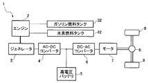
図1は、本発明の実施形態に係るデュアルフューエルエンジン2を搭載したハイブリッド車両1の構成図である。この車両1は、エンジン2と、ジェネレータ(発電機)3と、AC−DCコンバータ4と、高電圧バッテリ5と、DC−ACコンバータ6と、モータ7と、これらを制御するためのコントローラ20(図3参照)を備えている。
FIG. 1 is a configuration diagram of a
この車両1では、エンジン2は、コントローラ20からの制御信号によって作動し、エンジン2の回転出力によってジェネレータ3を駆動する。これにより、ジェネレータ3は、交流電力を発電し、AC−DCコンバータ4に交流電力を供給する。
AC−DCコンバータ4は、供給された交流電力を直流電力に変換し、直流電力を高電圧バッテリ5及びDC−ACコンバータ6に供給する。これにより、高電圧バッテリ5は、AC−DCコンバータ4から供給される直流電力によって充電されると共に、所定の運転状態において、DC−ACコンバータ6へ直流電力を供給する。
In the
The AC-
DC−ACコンバータ6は、運転状態に応じて、高電圧バッテリ5及びAC−DCコンバータ4の少なくとも一方から供給される直流電力を交流電力に変換する。モータ7は、DC−ACコンバータ6から供給される交流電力によって駆動され、回転出力をディファレンシャルギア8に伝達する。そして、このモータ出力は、ディファレンシャルギア8を介して駆動輪9に伝達され、これにより、車両1が走行するようになっている。
The DC-
このように、本実施形態の車両1は、シリーズ方式のハイブリッド車両であり、モータ7がエンジン2と高電圧バッテリ5を駆動源とする電力によって駆動され、モータ7の回転出力によって駆動輪9を駆動するように構成されている。
本実施形態の車両1は、シリーズ方式のハイブリッド車両であるが、これに限らず、パラレル方式又はスプリット方式のハイブリッド車両であってもよい。なお、この場合は、駆動輪をモータの回転出力又はエンジンの回転出力が直接、機械的接続を介して駆動輪を駆動するので、エンジンとモータが駆動源となる。
As described above, the
The
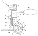
本実施形態のデュアルフューエルエンジン2は、燃焼時の熱量が低い非炭化水素系の第1燃料である水素ガスと、第1燃料に対し燃焼時の熱量が高い炭化水素系の第2燃料であるガソリンを使用燃料としている。体積当りではガソリンの方が水素ガスよりも燃焼時の熱量が高く、本実施形態では、ガソリン運転モードの方が水素ガス運転モードよりも燃焼時の熱量が高い運転が行われ、このエンジン2では、同じエンジン回転数(rpm)及びスロットル開度でのエンジントルクは、ガソリン運転の方が水素ガス運転よりも大きくなる。
The
図2に示すように、エンジン2は、トロコイド内周面を有するロータハウジングとその両側に配置されたサイドハウジングとからなるハウジング10と、ハウジング10内に形成されたロータ収容室(以下、「気筒」という)11に配置された概略三角形状のロータ12とを備えたロータリーエンジンである。
このエンジン2は、2つのロータハウジングを3つのサイドハウジングの間に挟みこむようにして一体化し、その間に形成される2つの気筒11にそれぞれロータ12を収容した2ロータタイプであり、図2では、一方の気筒11のみを示している。
As shown in FIG. 2, the
The
ロータ12は、エキセントリックシャフト13に支持されており、このエキセントリックシャフト13と共に、偏心回転するように構成されている。ロータ12は、外周の3つの頂部にそれぞれ配設されたシール部がロータハウジングのトロコイド内周面に当接した状態で偏心回転を行う。気筒11内には、ロータ12の外周側に3つの作動室が区画される。この作動室の容積は、ロータ12の偏心回転により変化する。そして、作動室における吸気,圧縮,膨張(燃焼)及び排気の一連の工程により、ロータ12及びエキセントリックシャフト13が回転し、この回転出力がジェネレータ3側に伝達される。
The
以下の説明において、各ロータ12に対するスロットル弁17下流側の構成は同様である。
ハウジング10には、各気筒11に2つの点火プラグ14が設けられている。また、ハウジング10には、吸気ポート15a及び排気ポート15bが形成されており、吸気ポート15aには吸気通路16aが接続され、排気ポート15bには排気通路16bが接続されている。吸気通路16aを介して、吸気工程にある作動室に空気が導入され、排気通路16bを介して、排気工程にある作動室から排気ガスが排出される。
In the following description, the configuration on the downstream side of the
In the
また、吸気通路16aの上流側には電磁弁であるスロットル弁17が配設され、さらに上流側にはエアクリーナ19が配設されている。スロットル弁17には、開度を検出するスロットル開度センサ18が設けられている。
さらに、吸気通路16aの最下流側の吸気ポート15a近傍には、ガソリンを噴射して空気とガソリンとの混合気を作動室内に供給するガソリンインジェクタ30と、水素ガスを噴射して水素ガスと空気との混合気を作動室内に供給するポート噴射式の水素ガスインジェクタ40aが配設されている。
A
Further, in the vicinity of the
ガソリンインジェクタ30は、ガソリン供給通路31を介してガソリンタンク32に接続されている。ガソリンタンク32は、所定容量のガソリンを貯留する本体部に、ガソリンポンプ33等が配設されて構成されている。
ガソリンポンプ33は、ガソリン供給通路31を介してガソリンインジェクタ30にガソリンを圧送するように構成されている。
The
The
また、ハウジング10には、水素ガスを作動室内に直接噴射する直噴式の水素ガスインジェクタ40bが配設されている。水素ガスインジェクタ40a,40bは、途中で合流する水素ガス供給通路41を介して水素高圧ガスタンク42に接続され、この水素高圧ガスタンク42から水素ガスが供給される。
水素高圧ガスタンク42の排出口には、タンクから水素ガス供給通路41への水素ガスの供給を制御するための停止弁43が設けられ、さらに下流側には、水素ガスインジェクタ40a,40bへの水素ガス供給量(供給圧力)を制御する制御弁44が配設されている。インジェクタ30,40a,40bは、コントローラ20からの制御信号に基づいて、所定の噴射タイミングで、所定量のガソリン又は水素ガスを噴射するように構成されている。
Further, the
The discharge port of the hydrogen high-
コントローラ20は、周知のマイクロコンピュータをベースとする制御装置であって、エンジン制御方法を記憶したプログラムを実行する中央演算処理装置(CPU)と、例えばRAMやROMにより構成されてプログラム及びデータを格納するメモリと、電気信号の入出力をする入出力(I/O)バス等を備えている。
The
図3に示すように、コントローラ20は、ジェネレータ3,AC−DCコンバータ4,DC−ACコンバータ6,モータ7,点火プラグ14,スロットル弁17,スロットル開度センサ18,ガソリンインジェクタ30,水素ガスインジェクタ40a及び40b,運転モード選択スイッチ60,アクセル開度センサ61,車速センサ62,エンジン回転数センサ63,バッテリ電圧センサ23,バッテリ電流センサ24等に接続され、これらのうち検出センサから検出信号を受け取り、制御対象に制御信号を出力することにより動作制御を行う。
As shown in FIG. 3, the
コントローラ20は、バッテリコントローラ21と、HEVコントローラ22とを有している。なお、バッテリコントローラ21の機能をHEVコントローラ22に組み込んで、コントローラ20をHEVコントローラ22のみに一体化した構成としてもよい。また、以下に説明するバッテリコントローラ21とHEVコントローラ22の各機能の分担をコントローラ20内で変更してもよい。コントローラ20は、後述するセンサ等を含んで本発明の車両用バッテリの充電制御装置を構成する。
The
バッテリコントローラ21は、SOC制御を行うように構成されている。すなわち、バッテリコントローラ21は、バッテリ5の蓄電量(SOC)を使用範囲(充放電範囲)内に保持するように充電要求信号をHEVコントローラ22に出力する。SOCは、バッテリの電気容量に対して充電している電気量を比率で表したものである。本明細書では、蓄電量をSOCと同義で使用する。
The
本実施形態では、バッテリ5のSOCの通常の使用範囲は、上限値が60%,下限値が40%に規定されている。この使用範囲は、SOC50%を中心として上限方向及び下限方向にそれぞれ10%の幅を有し、全体として使用範囲幅が20%となるように設定されている。これにより、バッテリ5の過放電及び満充電を抑制すると共に、バッテリ5によるモータ7の駆動範囲を比較的大きく設定して、バッテリ走行を増やし、エンジン運転を抑制して、燃費向上を図ることができる。
また、バッテリコントローラ21は、所定条件でバッテリ5のSOCの使用範囲の下限値を上限値より小さい値の範囲で引き上げる処理を行う。この処理は、後述するように、水素ガス運転モードにおけるSOCの下限値を、ガソリン運転モードにおけるSOCの下限値よりも引き上げる処理である。
In the present embodiment, the normal use range of the SOC of the
Further, the
バッテリコントローラ21は、バッテリ電圧センサ23,バッテリ電流センサ24等と接続されている。
バッテリ電圧センサ23,バッテリ電流センサ24は、それぞれバッテリ5の電圧,電流を検出してバッテリコントローラ21に出力している。バッテリコントローラ21は、これらの電圧,電流検出値等に基づいてバッテリ5のSOCを算出する。具体的には、バッテリコントローラ21は、電流検出値を積算して電流の入力及び出力の合計から、SOCの変動分を計算し、さらに電圧検出値等とSOCとの対応関係を示す内部データを加味して補正することにより、現在のSOCを算出する。
The
The
そして、蓄電量判定手段としてのバッテリコントローラ21は、算出した現在のSOCが使用範囲の下限値を下回ると、HEVコントローラ22に充電要求信号を出力し、充電要求信号を出力後、原則的に、SOCが使用範囲の上限値に到達するまで充電要求信号を出力し続ける。HEVコントローラ22は、この充電要求信号を受けている間、充電制御を行う。
When the calculated current SOC falls below the lower limit value of the use range, the
また、HEVコントローラ22は、アクセル開度に応じて要求された駆動力をモータ7から駆動輪9に出力するように、エンジン2,ジェネレータ3,AC−DCコンバータ4,DC−ACコンバータ6及びモータ7等を制御するものである。
Further, the
本実施形態では、HEVコントローラ22は、運転条件に応じて、駆動源を切り替えてモータ7を駆動する制御を行う。すなわち、HEVコントローラ22は、エンジン2を運転して、これにより発電した電力でモータ7を駆動するか、高電圧バッテリ5からの電力によってモータ7を駆動するかを決定する。
In the present embodiment, the
具体的には、HEVコントローラ22は、アクセル開度センサ61及び車速センサ62からのアクセル及び車速を表す検出信号に基づいて、エンジン2の運転要求の有無、つまりエンジン2を運転させる必要があるか否かを判定する。
Specifically, the
この判定のために、HEVコントローラ22は、エンジン2と高電圧バッテリ5のいずれを使用してモータ7を駆動するのかを、アクセル開度と車速との関係に応じて決定するためのマップデータ(図示せず)を記憶している。このマップデータに基づいて、HEVコントローラ22は、要求トルクが低い低トルク運転時や車両始動時には、高電圧バッテリ5から供給される電力によりモータ7を駆動するように制御を行う。また、HEVコントローラ22は、中トルク運転時には、エンジン2により駆動されるジェネレータ3から供給される電力によりモータ7を駆動するように制御を行う。さらに、HEVコントローラ22は、要求トルクが高い高トルク運転時には、ジェネレータ3及び高電圧バッテリ5の双方から供給される電力によってモータ7を駆動するように制御を行う。
For this determination, the
また、本実施形態では、HEVコントローラ22は、バッテリコントローラ21から充電要求信号を受け取り、これに基づいてバッテリ5の充電制御を行う。すなわち、HEVコントローラ22は、高電圧バッテリ5の蓄電量が少なくなり、バッテリコントローラ21から充電要求信号を受け取ると、要求出力に応じたモータ7の駆動のために必要な電力に加えて、高電圧バッテリ5を充電するために必要な電力を余分にジェネレータ3で発生させるようにエンジン2を運転して、モータ7を駆動すると共に、高電圧バッテリ5の充電を行うようにエンジン2の制御を行う。
In the present embodiment, the
このとき、HEVコントローラ22は、モータ7を駆動するために必要な電力以上の発電量が得られるように、モータ駆動分の電力を発電するために必要なエンジン回転数よりも増大したエンジン回転数となるようにエンジン2を制御する。
At this time, the
また、本実施形態では、車両1には、運転者により選択可能な運転モード選択スイッチ60が設けられている。運転者は、この運転モード選択スイッチ60を操作することにより、エンジン2の運転モードを、水素ガスによる第1運転モードと、ガソリンによる第2運転モードとの間で択一的に選択可能となっている。HEVコントローラ22は、運転モード選択スイッチ60の操作により出力される運転モード選択信号を受け取り、運転モード選択信号で選択されている運転モードでエンジン2を運転するように、点火時期,使用燃料,スロットル開度等を制御するエンジン制御処理を行う。
In the present embodiment, the
なお、本実施形態では、運転者が運転モード選択スイッチ60を手動で操作することにより、運転モードが選択されるように構成されているが、これに限らず、要求トルク等に基づく運転状態や水素ガス残量等に応じて、コントローラ20が、水素ガス運転モードとガソリン運転モードの間で運転モードを自動的に切り替えるように構成してもよい。
In the present embodiment, the operation mode is selected by manually operating the operation
次に、本実施形態によるエンジン制御の概略について説明する。
図4は、アクセル開度とモータ7への要求出力との関係を表したマップデータである。HEVコントローラ22は、運転者がアクセルを操作することにより変動するアクセル開度αを表す信号をアクセル開度センサ61から受け取り、図4のマップデータに基づいて、要求出力を算出する。
Next, an outline of engine control according to the present embodiment will be described.
FIG. 4 is map data representing the relationship between the accelerator opening and the required output to the
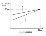
また、図5は、定常状態におけるエンジン回転数(rpm)とエンジン出力(kW)との関係を表したマップデータである。なお、図5中、実線Aはガソリン運転モードを表し、破線Bは水素ガス運転モードを表している。これらは、最大エンジン回転数Nmaxで最大エンジン出力Pmaxが得られるように、チューニングされている。 FIG. 5 is map data showing the relationship between the engine speed (rpm) and the engine output (kW) in a steady state. In FIG. 5, a solid line A represents a gasoline operation mode, and a broken line B represents a hydrogen gas operation mode. These are tuned so that the maximum engine output P max can be obtained at the maximum engine speed N max .
ガソリン運転モードでは、実線Aのような関係が得られるように、HEVコントローラ22は、少なくとも高回転域においてスロットル開度がアクセル開度に比べて絞られるように制御を行う。一方、水素ガス運転モードでは、HEVコントローラ22は、常時、スロットル開度を全開位置に保持し、目標とするエンジン回転数を達成するように、ジェネレータ3側の負荷を調整する制御を行う。
In the gasoline operation mode, the
HEVコントローラ22は、アクセル開度αに基づいて算出した要求出力を達成するエンジン回転数を、図5のマップデータに基づいて算出する。そして、HEVコントローラ22は、このエンジン回転数を達成するように、ガソリン運転及び水素ガス運転モードともに主にジェネレータ3による動力吸収を弱めたり強めたりする制御を行う。
The
次に、図6及び図7に基づいて、本実施形態のコントローラ20の充電制御の概略を説明する。
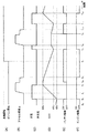
図6は、充電制御のタイミングチャートであり、同図(A)は運転モード選択スイッチ60で選択された運転モードの時間変化を示し、同図(B)はアクセル開度αの時間変化を示し、同図(C)は充電処理実施の有無の時間変化を示し、同図(D)はバッテリ5のSOCの時間変化を示し、同図(E)はバッテリ5からモータ7への電力供給の有無の時間変化を示し、同図(F)はジェネレータ3を介したエンジン2からモータ7への電力供給の有無の時間変化を示している。
Next, based on FIG.6 and FIG.7, the outline of the charge control of the
FIG. 6 is a timing chart of the charge control. FIG. 6A shows the time change of the operation mode selected by the operation
運転者は、運転モード選択スイッチ60により、時間t0から時間t6までは継続してガソリン運転モードを運転モードに選択し、時間t6に運転モードを水素ガス運転モードに切り替え、時間t6以降は水素ガス運転モードを運転モードに選択している。
また、運転者は、時間t0から時間t2まではアクセルを一定に保持し、時間t2から時間t5までの間にアクセルを一旦踏み込んで再び戻している。その後、運転者は、時間t5から時間t8まではアクセルを一定に保持し、時間t8から時間10の間にアクセルを一旦踏み込んで再び戻し、それ以降アクセルを一定に保持している。
Driver, the operation
The driver keeps the accelerator constant from time t 0 to time t 2 , and once depresses the accelerator to return again from time t 2 to time t 5 . Then, the driver, from the time t 5 to time t 8 holds the accelerator constant, back again depresses once the accelerator during the time t 8 of time 10, holds a subsequent acceleration constant.
時間t0から時間t1までは、エンジン2が駆動されず、バッテリ5のみからモータ7へ電力が供給されている。これにより、時間t1に、バッテリ5のSOCが通常の下限値である40%まで減少している。
バッテリ5のSOCが下限値に到達したことにより、バッテリコントローラ21は、HEVコントローラ22に充電要求信号を出力する。これにより、充電制御手段としてのHEVコントローラ22は、停止状態のエンジン2を駆動すると共に、バッテリ5からモータ7への電力供給を停止する。そして、HEVコントローラ22は、エンジン2からジェネレータ3を介して、モータ7に駆動電力を供給すると共に、バッテリ5に充電電力を供給する。
From time t 0 to time t 1 , the
When the SOC of the
ジェネレータ3によりバッテリ5を充電することにより、時間t1以降、バッテリ5のSOCは上昇していき、時間t3に上限値である60%に到達する。これにより、バッテリコントローラ21は、充電要求信号の出力を停止し、時間t3に充電が終了する。
また、時間t2以降の所定期間、アクセルが踏み込まれ、アクセル開度αの時間変化率が正又は所定値より大きくなるので、加速要求判定手段としてのHEVコントローラ22は、加速要求有りと判断する。これにより、モータ7の要求出力が増加するので、HEVコントローラ22は、要求出力増加分に応じてエンジン回転数を増大させる。
By charging the
Further, since the accelerator is depressed for a predetermined period after time t 2 and the time change rate of the accelerator opening α becomes positive or larger than a predetermined value, the
時間t3に充電が終了した後、HEVコントローラ22は、時間t4に、ジェネレータ3に加えて、バッテリ5からモータ7へ電力を供給する制御を行う。これにより、時間t4以降は、バッテリ5のSOCが減少していく。
時間t5に、アクセルが戻された状態で一定に保持されると、車両1は定常運転に移行する。これに伴い、HEVコントローラ22は、エンジン2を停止し、バッテリ5のみからモータ7へ電力を供給する制御を行う。これにより、継続的にバッテリ5のSOCが減少していく。
After charging is completed at time t 3 , the
The time t 5, when it is held constant while the accelerator is returned, the
時間t6に、運転モードが水素ガス運転モードに切り替えられると、バッテリコントローラ21は、HEVコントローラ22を介して水素ガス運転モードを表す運転モード選択信号を受け取り、SOCの下限値を45%に引き上げる処理を行う。
時間t7に、バッテリ5のSOCが、引き上げられた下限値である45%まで低下すると、HEVコントローラ22は、エンジン2を駆動すると共に、バッテリ5からモータ7への電力供給を停止する。そして、HEVコントローラ22は、エンジン2からジェネレータ3を介して、モータ7へ駆動電力を供給すると共に、バッテリ5へ充電電力を供給する。これにより、バッテリ5のSOCは上昇し始める。
When the operation mode is switched to the hydrogen gas operation mode at time t 6 , the
When the SOC of the
ところが、時間t8に、アクセルが踏み込まれ、アクセル開度αの時間変化率が正又は所定値より大きくなると、HEVコントローラ22は、加速要求有りと判断する。これにより、モータ7の要求出力が増加する。充電抑制制御手段としてのHEVコントローラ22は、水素ガス運転モードでは、加速要求が生じると、充電要求が有る場合であっても、充電を抑制する制御を行う。
However, when the accelerator is depressed at time t 8 and the time change rate of the accelerator opening α becomes positive or larger than a predetermined value, the
上述のように、水素ガス運転モードでは、同じエンジン出力を供給するのに、ガソリン運転モードと比べてエンジン回転数が高くなる。また、ガソリン運転では、要求されたトルクに対して出力に余裕があるため、負荷が大きくなってもエンジン回転数がそれほど増速されない。そして、加速要求が有る場合には、さらにエンジン回転数が高くなるが、これに加えて充電要求があると、さらにエンジン回転数が高くなってしまう。これにより、ガソリン運転モードと比べて、水素ガス運転モードでは、運転者に与えるエンジンからの騒音が大きくなり、また、エンジン回転数やエンジン音の割りに加速感が低下しているような印象を運転者に与えるおそれがある。 As described above, in the hydrogen gas operation mode, the engine speed is higher than that in the gasoline operation mode to supply the same engine output. In gasoline operation, since the output has a margin with respect to the required torque, the engine speed is not increased so much even if the load increases. When there is an acceleration request, the engine speed further increases, but when there is a charge request in addition to this, the engine speed further increases. As a result, in the hydrogen gas operation mode, the noise from the engine given to the driver increases in comparison with the gasoline operation mode, and the feeling of acceleration is reduced for the engine speed and engine sound. There is a risk of giving it to the driver.
このため本実施形態では、水素ガス運転モード時には、充電要求があっても、加速要求が生じた場合には、加速要求を優先させて、充電を抑制するように構成されている。したがって、HEVコントローラ22は、充電のためにエンジン回転数を増大させることなく、加速要求に応じたエンジン回転数でエンジン2を制御する。これにより、水素ガス運転モードにおいて、エンジン回転数の高回転化を抑制することができる。
なお、本実施形態の充電抑制制御処理では、充電が完全に停止されるが、これに限らず、充電量を低下させるように、充電分に相当するエンジン回転数の増加量を所定回転数に低下させるようにしてもよい。
Therefore, in the present embodiment, in the hydrogen gas operation mode, even when there is a charge request, if an acceleration request is generated, the acceleration request is prioritized and charging is suppressed. Therefore, the
In the charging suppression control process of the present embodiment, charging is completely stopped. However, the present invention is not limited to this, and the increase amount of the engine speed corresponding to the charge amount is set to a predetermined speed so as to reduce the charge amount. You may make it reduce.
また、本実施形態では、水素ガス運転モードでは、充電要求があっても加速要求が生じた場合は、バッテリ5の充電が抑制されるため、バッテリ5が充電される期間が少なくなる。したがって、バッテリ5が過放電されてしまうおそれがある。
しかしながら、本実施形態では、ガソリン運転モードよりも水素ガス運転モードでは、バッテリ5のSOCの下限値、すなわち充電開始電圧が引き上げられているので、加速要求がない状態では、バッテリ5のSOCを高めに保持することができる。これにより、加速要求が生じたときに、バッテリ5が過放電されるおそれを低減することが可能となる。
Further, in the present embodiment, in the hydrogen gas operation mode, when an acceleration request is generated even when there is a charging request, charging of the
However, in the present embodiment, in the hydrogen gas operation mode, the lower limit value of the SOC of the
時間t8に充電が停止されると、このときバッテリ5はモータ7を駆動するために用いられていないので、バッテリ5のSOCは一定に保持される。そして、時間t9に、HEVコントローラ22が、ジェネレータ3に加えて、バッテリ5からの電力をモータ7へ供給するように制御を行うと、バッテリ5のSOCが減少していく。
When the charging time t 8 is stopped, so this time the
時間t10に、アクセルが戻された状態で一定に保持され、車両1は定常運転に移行する。そして、時間t11に、バッテリ5のSOCが、引き上げられた下限値である45%まで再び低下すると、HEVコントローラ22は、バッテリ5からモータ7への電力供給を停止し、モータ7への要求出力と充電分を満足するようにエンジン回転数を増大させる制御を行う。これにより、バッテリ5のSOCは、時間t11から増加し始め、時間t12に上限値である60%に到達する。
The time t 10, is held constant while the accelerator is returned, the
バッテリ5のSOCが上限値に到達すると、バッテリコントローラ21は充電要求信号の出力を停止し、時間t12に、HEVコントローラ22は充電を終了する。
時間t12以降は、エンジン2が停止され、バッテリ5からモータ7へ電力供給がされる。これにより、バッテリ5のSOCは、時間と共に低減していく。
なお、本実施形態では、水素ガス運転モードで加速要求が有った場合、充電が中止されるように構成されているが、これに限らず、加速要求が生じると充電を一旦停止し、その後加速要求が無くなったときに充電を再開するように構成してもよい。
When SOC of the
Time t 12 after the
In the present embodiment, when there is an acceleration request in the hydrogen gas operation mode, the charging is configured to be stopped. However, not limited to this, the charging is temporarily stopped when the acceleration request is generated, and then You may comprise so that charge may be restarted when an acceleration request | requirement is lost.
図7は、本実施形態の充電抑制制御のフローチャートである。
この制御フローは、エンジン2が始動されることに開始され、まず、コントローラ20(HEVコントローラ22)は、運転モード選択スイッチ60から受け取っている運転モード選択信号を読み込む(ステップS1)。次いで、HEVコントローラ22は、バッテリコントローラ21から受け取っているバッテリ5のSOCを表す信号から、現在のSOCを読み込む(ステップS2)。
FIG. 7 is a flowchart of the charge suppression control of this embodiment.
This control flow is started when the
次いで、HEVコントローラ22は、読み込んだ運転モード選択信号が水素運転モードを表しているか否かを判定する(ステップS3)。
読み込んだ運転モード選択信号が水素運転モードを表している場合(ステップS3;Yes)、水素ガス運転モードが選択されており、コントローラ20(バッテリコントローラ21)は、読み込んだバッテリ5のSOCが、選択されている水素ガス運転モードに対応して、ガソリン運転モード時よりも引き上げて設定したバッテリ5のSOCの下限値である45%を下回るか否かを判定する(ステップS4;蓄電量判定ステップ)。
Next, the
When the read operation mode selection signal indicates the hydrogen operation mode (step S3; Yes), the hydrogen gas operation mode is selected, and the controller 20 (battery controller 21) selects the SOC of the read
読み込んだバッテリ5のSOCが引き上げられた下限値(45%)を下回っている場合(ステップS4;Yes)、バッテリコントローラ21は、充電要求信号を出力し、ステップS6へ移行する。
When the SOC of the read
一方、バッテリ5のSOCが引き上げられた下限値(45%)を下回っていない場合(ステップS4;No)、コントローラ20(HEVコントローラ22)は、現在が充電中であるか否かを判定する(ステップS5)。この場合、既に、HEVコントローラ22が、バッテリコントローラ21から充電要求信号を受け取り、この充電要求信号に基づいて、バッテリ5への充電制御を行っている場合に、充電中であると判定する。
On the other hand, when the SOC of the
現在が充電中である場合(ステップS5;Yes)、現在のSOCが下限値以上であるが上限値まで到達していないので、バッテリコントローラ21は引き続き充電要求信号を出力し、ステップS6へ移行する。
一方、現在が充電中でない場合(ステップS5;No)、充電中でなくバッテリ5のSOCが使用範囲内(45%〜60%)に維持されているので、処理を終了して、再びステップS1へ戻る。
If the battery is currently being charged (step S5; Yes), the current SOC is equal to or higher than the lower limit value but has not reached the upper limit value. Therefore, the
On the other hand, when the battery is not currently charged (step S5; No), the
ステップS6では、コントローラ20(HEVコントローラ22)は、アクセル開度センサ61から読み込んだアクセル開度αに基づいて、運転者から車両1に対して加速要求が有るか否かを判定する(ステップS6;加速要求判定ステップ)。すなわち、ステップS6では、アクセル開度αの時間変化が正であるか否か、又は所定の正の閾値α0よりも大きいか否かが判定され、直近のアクセル開度αの時間変化Δαが正、又は閾値α0よりも大きければ、アクセルが運転者によって踏み込まれ、加速要求があると判定される。
In step S6, the controller 20 (HEV controller 22) determines whether or not there is an acceleration request from the driver to the
加速要求が有る場合(ステップS6;Yes)、水素ガス運転モード中に、充電要求があり且つ加速要求があるので、充電要求に応じて充電を行うと、エンジン回転数が大きくなり過ぎてしまうので、充電制御を抑制すべく、充電制御を停止して(ステップS9;充電抑制ステップ)、再びしステップS1へ戻る。このように、加速要求が有ると判定された場合は、充電要求が新たに生じたとき及び既に充電要求に応じて充電中であるときに関わらず、充電制御が抑制される。 When there is an acceleration request (step S6; Yes), there is a charge request and an acceleration request during the hydrogen gas operation mode, so if charging is performed according to the charge request, the engine speed will become too large. In order to suppress the charge control, the charge control is stopped (step S9; charge suppression step), and the process returns to step S1. As described above, when it is determined that there is an acceleration request, charging control is suppressed regardless of whether a charging request is newly generated or when charging is already performed in response to the charging request.
一方、加速要求がない場合(ステップS6;No)、水素ガス運転モード中に、加速要求がない状態で充電要求が生じているので、コントローラ20(HEVコントローラ22)は、充電要求が新たに生じたときには充電制御を開始し、既に充電要求に応じて充電中であるときには引き続き充電制御を継続する(ステップS7;充電ステップ)。充電制御では、HEVコントローラ22は、モータ7への出力要求とバッテリ5を充電するために必要な出力とを加味したエンジン回転数でエンジン2を駆動し、これによりジェネレータ3を駆動して発電し、余剰電力でバッテリ5を充電する。この場合、例えば、エンジン回転数は、1000rpm程度増速される。
On the other hand, when there is no acceleration request (step S6; No), the charge request is generated in the hydrogen gas operation mode without the acceleration request. Therefore, the controller 20 (HEV controller 22) newly generates a charge request. When the charging is started, the charging control is started. When the charging is already performed in response to the charging request, the charging control is continued (step S7; charging step). In the charging control, the
次いで、コントローラ20(HEVコントローラ22)は、バッテリ5の現在のSOCが上限値(60%)に到達しているか否かを判定する(ステップS8)。
バッテリ5の現在のSOCが上限値(60%)に到達している場合(ステップS8;Yes)、HEVコントローラ22は、充電制御を停止し、処理を終了して、再びステップS1へ戻る。
一方、バッテリ5の現在のSOCが上限値(60%)に到達していない場合(ステップS8;No)、HEVコントローラ22は、充電制御を停止することなく、充電制御を継続すべく、再びステップS1に戻る。
Next, the controller 20 (HEV controller 22) determines whether or not the current SOC of the
When the current SOC of the
On the other hand, if the current SOC of the
一方、読み込んだ運転モード選択信号が水素運転モードを表していない場合(ステップS3;No)、すなわちガソリン運転モードが選択されている場合、コントローラ20(バッテリコントローラ21)は、読み込んだバッテリ5のSOCが、選択されているガソリン運転モードに対応して設定したバッテリ5のSOCの下限値(40%)を下回るか否かを判定する(ステップS10;蓄電量判定ステップ)。
On the other hand, when the read operation mode selection signal does not represent the hydrogen operation mode (step S3; No), that is, when the gasoline operation mode is selected, the controller 20 (battery controller 21) reads the SOC of the read
読み込んだバッテリ5のSOCが通常の下限値(40%)を下回っている場合(ステップS10;Yes)、バッテリコントローラ21は充電要求信号を出力し、HEVコントローラ22は、ステップS7〜S9で上述のようにSOCの上限値の範囲内で充電制御を行う。
一方、バッテリ5のSOCが通常の下限値(40%)を下回っていない場合(ステップS10;No)、コントローラ20(HEVコントローラ22)は、現在が充電中であるか否かを判定する(ステップS11)。
When the SOC of the read
On the other hand, when the SOC of the
現在が充電中である場合(ステップS11;Yes)、現在のSOCが下限値以上であるが上限値まで到達していないので、バッテリコントローラ21は引き続き充電要求信号を出力し、HEVコントローラ22は、ステップS7〜S9で上述のようにSOCの上限値の範囲内で充電制御を行う。
一方、現在が充電中でない場合(ステップS11;No)、充電中でなくバッテリ5のSOCが使用範囲内に維持されているので、処理を終了して、再びステップS1へ戻る。
When the current charging is in progress (step S11; Yes), since the current SOC is equal to or higher than the lower limit value but has not reached the upper limit value, the
On the other hand, when the battery is not currently being charged (step S11; No), the
以上のように、本実施形態では、ガソリン運転モードでは、バッテリ5のSOCが下限値(40%)を下回ると、モータ7に対する要求出力以上の電力を発生させるように、エンジン2の回転数を増大させる。そして、これによりジェネレータ3によって余剰電力を発電し、モータ7を駆動すると共に、この余剰電力によりバッテリ5を充電する充電制御を行う。この場合、この充電制御は、車両1への加速要求の有無に関わらず行われるように構成されている。
As described above, in the present embodiment, in the gasoline operation mode, when the SOC of the
一方、水素ガス運転モードでは、バッテリ5のSOCの下限値(45%)を下回ると、ガソリン運転モードと同様に、モータ7に対する要求出力以上の電力を発生させるように、エンジン2の回転数を増大させる。そして、これによりジェネレータ3によって余剰電力を発電し、モータ7を駆動すると共に、この余剰電力によりバッテリ5を充電する充電制御を行う。
On the other hand, in the hydrogen gas operation mode, when the SOC of the
しかしながら、水素ガス運転モードの場合、この充電制御は、車両1への加速要求が有る場合には、抑制されるように構成されている。したがって、水素ガス運転モードでは、充電要求があっても、さらに加速要求が存在する場合には、加速要求を優先させて、充電制御は行われない。これにより、加速要求時には、必要以上にエンジン回転数が高速化されることを抑制することができる。
However, in the hydrogen gas operation mode, this charging control is configured to be suppressed when there is an acceleration request to the
また、本実施形態では、水素ガス運転モードでは、充電要求があっても充電制御が抑制される場合があるので、バッテリ5のSOCの下限値を、ガソリン運転モードにおける下限値よりも5%引き上げる処理を行っている。これにより、水素ガス運転モードでは、バッテリ5のSOCがガソリン運転モード時よりも高めに保持されるので、充電制御が抑制されたときに、過放電となってしまうことを防止することができる。
Further, in the present embodiment, in the hydrogen gas operation mode, even if there is a charge request, the charge control may be suppressed. Therefore, the lower limit value of the SOC of the
次に、図8に基づいて本発明の他の実施形態について説明する。
第2実施形態では、水素ガス運転モードでは、加速要求が有っても、エンジン回転数Nを所定のエンジン回転数Nlimitまでの範囲で増大させて、増大させたことにより生じる余剰電力でバッテリ5を充電するように構成されている。
Next, another embodiment of the present invention will be described with reference to FIG.
In the second embodiment, in the hydrogen gas operation mode, even if there is an acceleration request, the engine speed N is increased in a range up to a predetermined engine speed N limit , and the battery is generated with surplus power generated by the increase. 5 is configured to be charged.
図8は、他の実施形態における充電抑制制御のフローチャートである。なお、図7の制御フローと共通の処理については、説明を省略する。
この制御フローは、図7の制御フローと同様に、エンジン2が始動されることに開始される。ステップS21及びS22は、図7のステップS1及びS2と同様である。
次いで、ステップS22に引き続いて、コントローラ20(HEVコントローラ22)は、アクセル開度センサ61から受け取ったアクセル開度αを表す信号からアクセル開度αを読み込み(ステップS3)、エンジン回転数センサ63から受け取ったエンジン回転数Nを表す信号からエンジン回転数Nを読み込む(ステップS24)。
FIG. 8 is a flowchart of charge suppression control in another embodiment. Note that a description of processing common to the control flow of FIG. 7 is omitted.
This control flow is started when the
Subsequently, following step S22, the controller 20 (HEV controller 22) reads the accelerator opening α from the signal representing the accelerator opening α received from the accelerator opening sensor 61 (step S3), and from the
ステップS25〜S31,S36及びS37は、図7のステップS3〜S9,S10及びS11と同様である。
ステップS28で加速要求が有る場合(ステップS28;Yes)、ステップS32へ移行する。
Steps S25 to S31, S36 and S37 are the same as steps S3 to S9, S10 and S11 of FIG.
If there is an acceleration request in step S28 (step S28; Yes), the process proceeds to step S32.
ステップS32では、エンジン回転数判定手段としてのコントローラ20(HEVコントローラ22)は、読み込んだエンジン回転数Nが、所定のエンジン回転数Nlimitと等しいか否かを判定する(ステップS32;エンジン回転数判定ステップ)。本実施形態では、このエンジン回転数Nlimitは、最大エンジン回転数Nmaxであり、エンジン回転数Nは、このエンジン回転数Nlimit以下に制限される。 In step S32, the controller 20 (HEV controller 22) as the engine speed determination means determines whether or not the read engine speed N is equal to a predetermined engine speed N limit (step S32; engine speed). Judgment step). In the present embodiment, the engine speed N limit is the maximum engine speed N max , and the engine speed N is limited to the engine speed N limit or less.
エンジン回転数Nが、所定のエンジン回転数Nlimitと等しくない場合(ステップS32;Yes)、すなわちエンジン回転数Nがエンジン回転数Nlimitよりも小さい場合、HEVコントローラ22は、現在のエンジン回転数Nが、モータ7に対する出力要求に応じた電力を発生させるのに必要なエンジン回転数から所定回転数(例えば、500rpm)だけ回転数を引き上げられたものであるか否かを判定する(ステップS34)。
When the engine speed N is not equal to the predetermined engine speed N limit (step S32; Yes), that is, when the engine speed N is smaller than the engine speed N limit , the
現在のエンジン回転数Nが、所定回転数だけ回転数を引き上げられたものでない場合(ステップS34;No)、HEVコントローラ22は、現在のエンジン回転数から、制限を受けるエンジン回転数Nlimitまでにまだ余裕があるので、所定回転数の範囲内で、且つ、エンジン回転数Nlimitを超えない範囲で、エンジン回転数Nを徐々に引き上げる制御を行う(ステップS35)。
When the current engine speed N is not increased by a predetermined speed (step S34; No), the
例えば、エンジン回転数Nlimitが6000rpmであり、現在のエンジン回転数Nが5000rpmである場合は、引き上げる最大の回転数を500rpmに設定しているので、エンジン回転数Nを5500rpmまで引き上げられる。 For example, when the engine rotational speed N limit is 6000 rpm and the current engine rotational speed N is 5000 rpm, the maximum rotational speed to be increased is set to 500 rpm, so the engine rotational speed N can be increased to 5500 rpm.
一方、現在のエンジン回転数Nが5600rpmである場合は、所定の回転数(500rpm)だけ回転数を増大させると、エンジン回転数Nlimitを超えてしまうので、超えない範囲の400rpmに増大する回転数が抑制される。これにより、エンジン回転数Nを6000rpmまで引き上げられる。
すなわち、本実施形態では、所定の回転数分だけエンジン回転数Nを増大させるように、ステップS32〜S34の処理を繰り返していった場合に、途中でエンジン回転数Nがエンジン回転数Nlimitに到達すると(ステップS32;Yes)、エンジン回転数の増大が制限される(充電抑制ステップ)。
On the other hand, if the current engine speed N is 5600 rpm, increasing the engine speed by a predetermined engine speed (500 rpm) will exceed the engine engine speed N limit. Number is suppressed. Thereby, the engine speed N is raised to 6000 rpm.
That is, in this embodiment, when the processes of steps S32 to S34 are repeated so as to increase the engine speed N by a predetermined speed, the engine speed N is changed to the engine speed N limit on the way. When it reaches (step S32; Yes), the increase in the engine speed is limited (charging suppression step).
このように、エンジン回転数Nを最大エンジン回転数まで高速化することにより、余剰の電力を発生させることができ、この余剰電力によりバッテリ5を充電することが可能となる。
一方、現在のエンジン回転数Nが、所定回転数の範囲内で回転数を引き上げられたものである場合(ステップS34;Yes)、エンジン回転数Nは既に余剰電力を発生させるべく引き上げられているので、HEVコントローラ22は、増大されたエンジン回転数分で発電される余剰電力により、バッテリ5をSOCの上限値の範囲内で充電する制御を行う(ステップS29〜S31)。
Thus, by increasing the engine speed N to the maximum engine speed, surplus power can be generated, and the
On the other hand, when the current engine speed N has been increased within the range of the predetermined engine speed (step S34; Yes), the engine speed N has already been increased to generate surplus power. Therefore, the
エンジン回転数Nが、所定のエンジン回転数Nlimitと等しい場合(ステップS32;Yes)、HEVコントローラ22は、充電中であるか否かを判定する(ステップS33)。
充電中でない場合(ステップS33;No)、水素ガス運転モードにおいて、モータ7への出力要求により、エンジン2が制限を受ける最大のエンジン回転数Nlimitで運転しているので、HEVコントローラ22は、充電制御のために、エンジン回転数Nをこれ以上高速化することができないので、処理を終了して、再びステップS21へ戻る。
When the engine speed N is equal to the predetermined engine speed N limit (step S32; Yes), the
When charging is not being performed (step S33; No), in the hydrogen gas operation mode, the
一方、充電中である場合(ステップS33;Yes)、水素ガス運転モードにおいて、後述する処理によって、充電制御のためにエンジン回転数Nが、制限を受ける最大のエンジン回転数Nlimitまで増大されているので、HEVコントローラ22は、増大されたエンジン回転数分で発電される余剰電力により、バッテリ5をSOCの上限値の範囲内で充電する制御を行う(ステップS29〜S31)。
On the other hand, when charging is in progress (step S33; Yes), in the hydrogen gas operation mode, the engine speed N is increased to the maximum engine speed N limit that is restricted for charge control by the processing described later. Therefore, the
なお、本実施形態では、所定のエンジン回転数Nlimitが、許容可能な最大のエンジン回転数Nmaxに設定されているが、これに限らず、比較的高回転のエンジン回転数に設定してもよい。このように設定することにより、水素ガス運転モードにおいて、充電中に、エンジン回転数Nを、この設定回転数以下に制限しつつ、充電制御を抑制することができる。 In this embodiment, the predetermined engine speed N limit is set to the maximum allowable engine speed N max , but is not limited to this, and is set to a relatively high engine speed. Also good. By setting in this way, in the hydrogen gas operation mode, charging control can be suppressed while charging the engine speed N to be equal to or lower than the set speed during charging.
1 ハイブリッド車両
2 デュアルフューエルエンジン
5 高電圧バッテリ
7 モータ
20 コントローラ
21 バッテリコントローラ
22 HEVコントローラ
60 運転モード選択スイッチ
DESCRIPTION OF
Claims (6)
前記エンジンにより前記発電機を駆動し、これにより発電した電力で前記バッテリを充電する充電ステップと、
車両に対する所定以上の加速要求の有無を判定する加速要求判定ステップと、
第1燃料によるエンジン運転中において、前記加速要求判定ステップで加速要求が有ると判定されたとき、前記充電ステップにおける充電を抑制する充電抑制ステップと、
を備えたことを特徴とする車両用バッテリの充電制御方法。 A dual fuel engine that is operated by selectively using either the first fuel having a low calorific value at the time of combustion or the second fuel having a high caloric value at the time of combustion with respect to the first fuel, and generates electric power by the driving force of the engine A charging control method for a vehicle battery in a hybrid vehicle comprising: a generator; a battery that can be charged by the generator; and a motor that can drive the vehicle by electric power from the generator and the battery,
A charging step of driving the generator by the engine and charging the battery with the generated power;
An acceleration request determination step for determining whether there is an acceleration request greater than or equal to a predetermined value for the vehicle;
During engine operation with the first fuel, when it is determined that there is an acceleration request in the acceleration request determination step, a charge suppression step for suppressing charging in the charging step;
A charging control method for a vehicle battery, comprising:
前記充電ステップは、前記蓄電量判定ステップでバッテリの蓄電量が所定の閾値未満であると判定された場合に実行されるものであって、
前記蓄電量判定ステップにおいて、第1燃料によるエンジン運転時の閾値は、第2燃料によるエンジン運転時の閾値よりも、大きな値に設定されることを特徴とする請求項1に記載の車両用バッテリの充電制御方法。 A storage amount determination step for determining whether the storage amount of the battery is less than a predetermined threshold;
The charging step is executed when it is determined in the storage amount determination step that the storage amount of the battery is less than a predetermined threshold,
2. The vehicle battery according to claim 1, wherein in the storage amount determination step, a threshold value during engine operation with the first fuel is set to a value larger than a threshold value during engine operation with the second fuel. Charge control method.
前記充電抑制ステップは、前記加速要求判定ステップで加速要求が有ると判定され、且つ、前記エンジン回転数判定ステップでエンジン回転数が所定値に到達したと判定されたときに実行されることを特徴とする請求項1又は2に記載の車両用バッテリの充電制御方法。 An engine speed determination step for determining whether or not the engine speed has reached a predetermined value;
The charge suppression step is executed when it is determined in the acceleration request determination step that there is an acceleration request, and it is determined in the engine speed determination step that the engine speed has reached a predetermined value. The charging control method for a vehicle battery according to claim 1 or 2.
前記エンジンにより前記発電機を駆動し、これにより発電した電力で前記バッテリを充電する制御を行う充電制御手段と、
車両に対する所定以上の加速要求の有無を判定する加速要求判定手段と、
第1燃料による運転中において、前記加速要求判定手段により加速要求が有ると判定されたとき、前記充電制御手段による充電制御を抑制する制御を行う充電抑制制御手段と、を備えたことを特徴とする車両用バッテリの充電制御装置。 A dual fuel engine that is operated by selectively using either the first fuel having a low calorific value at the time of combustion or the second fuel having a high caloric value at the time of combustion with respect to the first fuel, and generates electric power by the driving force of the engine A vehicle battery charge control device in a hybrid vehicle comprising: a generator; a battery that can be charged by the generator; and a motor that can drive the vehicle by electric power from the generator and the battery,
Charging control means for driving the generator by the engine and charging the battery with the electric power generated thereby;
Acceleration request determination means for determining whether or not there is an acceleration request greater than or equal to a predetermined value for the vehicle;
Charge suppression control means for performing control to suppress charge control by the charge control means when the acceleration request determination means determines that there is an acceleration request during operation with the first fuel, A vehicle battery charge control device.
前記充電制御手段は、前記蓄電量判定手段によりバッテリの蓄電量が所定の閾値未満であると判定された場合に、前記バッテリを充電する制御を行うものであって、
前記蓄電量判定手段は、第1燃料によるエンジン運転時の閾値を、第2燃料によるエンジン運転時の閾値よりも、大きな値に設定することを特徴とする請求項4に記載の車両用バッテリの充電制御装置。 The battery further comprises a storage amount determination means for determining whether the storage amount of the battery is less than a predetermined threshold value,
The charge control unit performs control for charging the battery when the storage amount determination unit determines that the storage amount of the battery is less than a predetermined threshold,
5. The vehicle battery according to claim 4, wherein the storage amount determination unit sets a threshold value during engine operation using the first fuel to a value larger than a threshold value during engine operation using the second fuel. Charge control device.
前記充電抑制制御手段は、前記加速要求判定手段により加速要求が有ると判定され、且つ、前記エンジン回転数判定手段によりエンジン回転数が所定値に到達したと判定されたときに、前記充電制御手段による充電制御を抑制する制御を行うことを特徴とする請求項4又は5に記載の車両用バッテリの充電制御装置。 Engine speed determining means for determining whether or not the engine speed has reached a predetermined value;
The charging control means is determined when the acceleration request determining means determines that there is an acceleration request and when the engine speed determining means determines that the engine speed has reached a predetermined value. 6. The vehicle battery charge control device according to claim 4, wherein control for suppressing charge control by the vehicle is performed.
Priority Applications (1)
| Application Number | Priority Date | Filing Date | Title |
|---|---|---|---|
| JP2008203406A JP5218832B2 (en) | 2008-08-06 | 2008-08-06 | Charge control method and charge control device for vehicle battery |
Applications Claiming Priority (1)
| Application Number | Priority Date | Filing Date | Title |
|---|---|---|---|
| JP2008203406A JP5218832B2 (en) | 2008-08-06 | 2008-08-06 | Charge control method and charge control device for vehicle battery |
Publications (2)
| Publication Number | Publication Date |
|---|---|
| JP2010036776A true JP2010036776A (en) | 2010-02-18 |
| JP5218832B2 JP5218832B2 (en) | 2013-06-26 |
Family
ID=42009763
Family Applications (1)
| Application Number | Title | Priority Date | Filing Date |
|---|---|---|---|
| JP2008203406A Expired - Fee Related JP5218832B2 (en) | 2008-08-06 | 2008-08-06 | Charge control method and charge control device for vehicle battery |
Country Status (1)
| Country | Link |
|---|---|
| JP (1) | JP5218832B2 (en) |
Cited By (1)
| Publication number | Priority date | Publication date | Assignee | Title |
|---|---|---|---|---|
| KR20180049412A (en) * | 2016-11-01 | 2018-05-11 | 한국생산기술연구원 | Pesticide spraying electric vehicles and their charging method |
Citations (5)
| Publication number | Priority date | Publication date | Assignee | Title |
|---|---|---|---|---|
| JPS5715652U (en) * | 1980-06-30 | 1982-01-27 | ||
| JP2000184509A (en) * | 1998-12-18 | 2000-06-30 | Honda Motor Co Ltd | Controller of hybrid vehicle |
| JP2002159101A (en) * | 2000-11-16 | 2002-05-31 | Mazda Motor Corp | Vehicle drive |
| JP2002218603A (en) * | 2001-01-18 | 2002-08-02 | Toyota Motor Corp | Power generation and charging control device for vehicle |
| JP2008101526A (en) * | 2006-10-18 | 2008-05-01 | Mazda Motor Corp | Control device of hybrid vehicle |
-
2008
- 2008-08-06 JP JP2008203406A patent/JP5218832B2/en not_active Expired - Fee Related
Patent Citations (5)
| Publication number | Priority date | Publication date | Assignee | Title |
|---|---|---|---|---|
| JPS5715652U (en) * | 1980-06-30 | 1982-01-27 | ||
| JP2000184509A (en) * | 1998-12-18 | 2000-06-30 | Honda Motor Co Ltd | Controller of hybrid vehicle |
| JP2002159101A (en) * | 2000-11-16 | 2002-05-31 | Mazda Motor Corp | Vehicle drive |
| JP2002218603A (en) * | 2001-01-18 | 2002-08-02 | Toyota Motor Corp | Power generation and charging control device for vehicle |
| JP2008101526A (en) * | 2006-10-18 | 2008-05-01 | Mazda Motor Corp | Control device of hybrid vehicle |
Cited By (2)
| Publication number | Priority date | Publication date | Assignee | Title |
|---|---|---|---|---|
| KR20180049412A (en) * | 2016-11-01 | 2018-05-11 | 한국생산기술연구원 | Pesticide spraying electric vehicles and their charging method |
| KR101925188B1 (en) * | 2016-11-01 | 2019-02-28 | 한국생산기술연구원 | Pesticide spraying electric vehicles and their charging method |
Also Published As
| Publication number | Publication date |
|---|---|
| JP5218832B2 (en) | 2013-06-26 |
Similar Documents
| Publication | Publication Date | Title |
|---|---|---|
| JP4135727B2 (en) | Power output apparatus, automobile equipped with the same, and control method for power output apparatus | |
| JP4519085B2 (en) | Control device for internal combustion engine | |
| JP4449917B2 (en) | Power output device, control method therefor, and vehicle equipped with power output device | |
| JP4853223B2 (en) | Control device for hybrid vehicle | |
| US8886380B2 (en) | Hybrid motor vehicle | |
| JP5734339B2 (en) | Series hybrid vehicle | |
| JP6380448B2 (en) | Hybrid vehicle | |
| JP2014172539A (en) | Hybrid vehicle control device | |
| JP2014172540A (en) | Control unit of hybrid vehicle | |
| JP2008038608A (en) | Control device for dual fuel engine | |
| JP5218832B2 (en) | Charge control method and charge control device for vehicle battery | |
| JP5796439B2 (en) | Hybrid car | |
| JP6361611B2 (en) | Control device for hybrid vehicle | |
| JPWO2012104962A1 (en) | Hybrid vehicle | |
| JP4844417B2 (en) | Control device | |
| JP6156285B2 (en) | Control device for hybrid vehicle | |
| JP2015074342A (en) | Control device of hybrid vehicle | |
| JP6269519B2 (en) | Multi-fuel engine fuel control system | |
| JP6160490B2 (en) | Hybrid car | |
| JP5104440B2 (en) | Engine fuel supply method and supply device | |
| JP2013230718A (en) | Exhaust gas purification device and control method of internal combustion engine | |
| JP2008101525A (en) | Control device of dual-fuel engine and control device of hybrid vehicle | |
| JP5082466B2 (en) | Control device for vehicle equipped with dual fuel engine | |
| JP2011025740A (en) | Drive control device of hybrid vehicle | |
| JP6354711B2 (en) | Engine control device for series hybrid vehicles |
Legal Events
| Date | Code | Title | Description |
|---|---|---|---|
| A621 | Written request for application examination |
Free format text: JAPANESE INTERMEDIATE CODE: A621 Effective date: 20110620 |
|
| A521 | Written amendment |
Free format text: JAPANESE INTERMEDIATE CODE: A523 Effective date: 20120329 |
|
| A977 | Report on retrieval |
Free format text: JAPANESE INTERMEDIATE CODE: A971007 Effective date: 20121112 |
|
| A131 | Notification of reasons for refusal |
Free format text: JAPANESE INTERMEDIATE CODE: A131 Effective date: 20121115 |
|
| A521 | Written amendment |
Free format text: JAPANESE INTERMEDIATE CODE: A523 Effective date: 20130108 |
|
| TRDD | Decision of grant or rejection written | ||
| A01 | Written decision to grant a patent or to grant a registration (utility model) |
Free format text: JAPANESE INTERMEDIATE CODE: A01 Effective date: 20130207 |
|
| A61 | First payment of annual fees (during grant procedure) |
Free format text: JAPANESE INTERMEDIATE CODE: A61 Effective date: 20130220 |
|
| FPAY | Renewal fee payment (event date is renewal date of database) |
Free format text: PAYMENT UNTIL: 20160315 Year of fee payment: 3 |
|
| R150 | Certificate of patent or registration of utility model |
Ref document number: 5218832 Country of ref document: JP Free format text: JAPANESE INTERMEDIATE CODE: R150 Free format text: JAPANESE INTERMEDIATE CODE: R150 |
|
| LAPS | Cancellation because of no payment of annual fees |